Green Packet Berhad OX250-GP Outdoor WiMAX CPE User Manual 0 5
Green Packet Berhad, Taiwan Outdoor WiMAX CPE 0 5
User Manual

1
User Manual
OX-250
WiMAX Outdoor CPE
Version 0.5
Nov. 8 , 2010
This Document may be subject to change, please contact with us for the latest version.
2
Federal Communication Commission Interference Statement
This equipment has been tested and found to comply with the limits for a Class B digital device,
pursuant to Part 15 of the FCC Rules. These limits are designed to provide reasonable
protection against harmful interference in a residential installation. This equipment generates,
uses and can radiate radio frequency energy and, if not installed and used in accordance with
the instructions, may cause harmful interference to radio communications. However, there is
no guarantee that interference will not occur in a particular installation. If this equipment does
cause harmful interference to radio or television reception, which can be determined by turning
the equipment off and on, the user is encouraged to try to correct the interference by one of the
following measures:
- Reorient or relocate the receiving antenna.
- Increase the separation between the equipment and receiver.
- Connect the equipment into an outlet on a circuit different from that to which the receiver
is connected.
- Consult the dealer or an experienced radio/TV technician for help.
FCC Caution: Any changes or modifications not expressly approved by the party responsible
for compliance could void the user's authority to operate this equipment.
This device complies with Part 15 of the FCC Rules. Operation is subject to the following two
conditions: (1) This device may not cause harmful interference, and (2) this device must
accept any interference received, including interference that may cause undesired operation.
IMPORTANT NOTE:
FCC Radiation Exposure Statement:
This equipment complies with FCC radiation exposure limits set forth for an uncontrolled
environment. This equipment should be installed and operated with minimum distance 50cm
between the radiator & your body.
This transmitter must not be co-located or operating in conjunction with any other antenna or
transmitter.
Due to the essential high output power natural of WiMAX device, use of this device with other
transmitter at the same time may exceed the FCC RF exposure limit and such usage must be
prohibited (unless such co-transmission has been approved by FCC in the future).

3
History
Revision Date of
Issue Scope Author
0.1 2010-10-14 First draft IChia Lin.
0.2 2010-10-18 Add specification IChia Lin
0.3 2010/1 0/26 Change min.30cm distance to 35cm,add
install and ground guide IChia Lin
0.4 2010/11/4 Update figure 70 IChia Lin
0.5 2010/11/8 Change min.35cm distance to 50cm IChia Lin
4
Table of Contents
History ...................................................................................................................................... 3
Table of Contents..................................................................................................................... 4
List of Figures.......................................................................................................................... 6
List of Tables............................................................................................................................ 9
1. Introduction...................................................................................................................11
1.1. Connect..............................................................................................................11
1.2. Logout............................................................................................................... 12
1.3. Status ................................................................................................................ 13
1.4. Device Status.................................................................................................... 13
1.5. Setup Wizard .................................................................................................... 15
2. Network.........................................................................................................................20
2.1. LAN.................................................................................................................... 20
2.1.1. IP........................................................................................................... 20
2.1.2. DHCP.................................................................................................... 21
2.2. WAN................................................................................................................... 23
2.2.1. WAN...................................................................................................... 24
2.2.2. DNS ...................................................................................................... 26
2.3. VLAN ................................................................................................................. 28
2.4. DDNS................................................................................................................. 29
3. Advanced Setting......................................................................................................... 32
3.1. NAT.................................................................................................................... 32
3.1.1. Port Forward........................................................................................ 32
3.1.2. Port Trigger.......................................................................................... 34
3.1.3. DMZ ...................................................................................................... 36
3.1.4. ALG ...................................................................................................... 37
3.2. Firewall.............................................................................................................. 38
3.2.1. IP Filter................................................................................................. 38
3.2.2. DOS ...................................................................................................... 40
3.3. Route................................................................................................................. 41
3.3.1. Static Route ......................................................................................... 41
3.3.2. RIP........................................................................................................ 43
3.4. UPnP.................................................................................................................. 46
3.4.1. UPnP Setting ....................................................................................... 46
3.5. IGMP Proxy....................................................................................................... 47
3.5.1. IGMP Proxy Setting............................................................................. 47
3.5.2. VPN Setting ......................................................................................... 48
3.6. PPTP.................................................................................................................. 48
3.6.1. PPTP Server ........................................................................................ 48
3.6.2. PPTP Client.......................................................................................... 51
3.6.3. L2TP ..................................................................................................... 53
3.6.4. L2TP Server......................................................................................... 53
3.6.5. L2TP Client .......................................................................................... 57
3.7. IPSec ................................................................................................................. 59
3.7.1. Connection .......................................................................................... 59
4. WiMAX...........................................................................................................................64
4.1. Profile................................................................................................................ 64
4.1.1. Connect Settings ................................................................................ 65
5
4.1.2. Frequency Settings............................................................................. 67
4.1.3. Authentication Settings ..................................................................... 69
4.2. Connect............................................................................................................. 72
4.3. Wide Scan......................................................................................................... 73
4.4. Link Status........................................................................................................ 74
4.5. Link Statistics................................................................................................... 75
4.6. Connection Info................................................................................................ 76
4.7. Service Flow..................................................................................................... 76
5. Administrator ............................................................................................................... 77
5.1. Remote Control................................................................................................ 77
5.1.1. HTTP..................................................................................................... 78
5.1.2. TELNET................................................................................................ 79
5.1.3. SSH....................................................................................................... 80
5.1.4. SNMP.................................................................................................... 81
5.1.5. TR-069.................................................................................................. 82
5.1.6. OMA-DM............................................................................................... 84
5.2. Password.......................................................................................................... 86
6. System ..........................................................................................................................88
6.1. Date and Time .................................................................................................. 88
6.1.1. Date ...................................................................................................... 89
6.1.2. Time Zone............................................................................................ 89
6.2. Upgrade Firmware ........................................................................................... 90
6.2.1. Upgrade File ........................................................................................ 90
6.2.2. Upgrade Link....................................................................................... 91
6.3. Log..................................................................................................................... 92
6.4. Backup/Restore................................................................................................ 92
6.4.1. Configuration Backup ........................................................................ 92
6.4.2. Configuration Restore........................................................................ 94
6.4.3. Factory Defaults.................................................................................. 95
7. Installing and grounding device................................................................................. 97
Specification ........................................................................................................................ 100
6
List of Figures
Figure 1 Login page....................................................................................................... 12
Figure 2 Logout.............................................................................................................. 12
Figure 3 Status window................................................................................................. 13
Figure 4 Device status................................................................................................... 14
Figure 5 Setup Wizard ................................................................................................... 15
Figure 6 Wizard LAN Settings in Setup Wizard .......................................................... 16
Figure 7 WiMAX Frequency Settings By List in Setup Wizard.................................. 17
Figure 8 WiMAX Frequency Settings By Range in Setup Wizard............................. 17
Figure 9 WiMAX Authentication Settings in Setup Wizard........................................ 18
Figure 10 Wizard Save..................................................................................................... 19
Figure 11 Network Topology........................................................................................... 20
Figure 12 Network>LAN>IP............................................................................................. 20
Figure 13 Network>LAN>DHCP...................................................................................... 22
Figure 14 Network>WAN>WAN....................................................................................... 24
Figure 15 Network>WAN>DNS ....................................................................................... 26
Figure 16 Network>VLAN................................................................................................ 28
Figure 17 Network>DDNS ............................................................................................... 30
Figure 18 Advanced>NAT>Port Forward....................................................................... 33
Figure 19 Advanced>NAT>Port Trigger......................................................................... 34
Figure 20 Advanced>NAT>DMZ...................................................................................... 36
Figure 21 Advanced>NAT>ALG...................................................................................... 37
Figure 22 Advanced>Firewall>IP Filter.......................................................................... 38
Figure 23 Advanced>Firewall>DDOS............................................................................. 40
Figure 24 Advanced>Route>Static Route ..................................................................... 41
7
Figure 25 Advanced>Route>Static Route>Add ............................................................ 41
Figure 26 Advanced>Route>RIP .................................................................................... 43
Figure 27 Advanced UPnP .............................................................................................. 46
Figure 28 Advanced>IGMP Proxy .................................................................................. 47
Figure 29 VPN>PPTP>Server.......................................................................................... 49
Figure 30 VPN>PPTP>Client........................................................................................... 51
Figure 31 VPN>PPTP>Client>Add.................................................................................. 51
Figure 32 VPN>L2TP>Server .......................................................................................... 54
Figure 33 VPN>L2TP>Client ........................................................................................... 57
Figure 34 VPN>L2TP>Client>Add .................................................................................. 57
Figure 35 VPN>IPsec Overview...................................................................................... 59
Figure 36 VPN>IPsec>Add.............................................................................................. 60
Figure 37 Wireless Broadband Access.......................................................................... 64
Figure 38 WiMAX>ProfiIe>Connect Settings ................................................................ 65
Figure 39 WiMAX>Profile>Frequency Settings>By List .............................................. 67
Figure 40 WiMAX>Profile>Frequency Settings>By Range.......................................... 68
Figure 41 WiMAX>ProfiIe>Authenticaton Settings (No Authentication).................... 69
Figure 42 WiMAX>ProfiIe>Authenticaton Settings (User Authentication)................. 70
Figure 43 WiMAX>Connect>Connect ............................................................................ 72
Figure 44 WiMAX>Wide Scan ......................................................................................... 73
Figure 45 WiMAX>link Status ......................................................................................... 74
Figure 46 WiMAX Link Statistics .................................................................................... 75
Figure 47 WiMAX Connection Info................................................................................. 76
Figure 48 WiMAX Service Flow ...................................................................................... 76
Figure 49 Administration>Remote Control>HTTP........................................................ 78
Figure 50 Administration>Remote Control>Telnet....................................................... 79
Figure 51 Administration>Remote Control>SSH.......................................................... 80
8
Figure 52 Administration>Remote Control>SNMP....................................................... 81
Figure 53 Administration>Remote Control>TR-069..................................................... 82
Figure 54 Administration>Remote Control>OMA-DM.................................................. 84
Figure 55 Administrator>Password ............................................................................... 86
Figure 56 System>Date/Time>Date................................................................................ 88
Figure 57 System>Date/Time>Time Zone...................................................................... 89
Figure 58 System>Upgrade Firmware>Upgrade File ................................................... 90
Figure 59 System>Upgrade Firmware>Upgrade Link.................................................. 91
Figure 60 System Log...................................................................................................... 92
Figure 61 System>Backup/Restore>Backup ................................................................ 92
Figure 62 File Download.................................................................................................. 93
Figure 63 Save File As..................................................................................................... 93
Figure 64 System>Backup/Restore>Restore................................................................ 94
Figure 65 System>Backup/Restore>Factory Defaults ................................................. 95
Figure 66 Restore to factory reset warning .................................................................. 96
Figure 67 Mounting accessory list....................................................................................... 97
Figure 68 Pole-Mount the Outdoor CPE Device ................................................................. 98
Figure 69 Wall-Mount the Outdoor CPE Device.................................................................. 98
Figure 70 Connect the ground wire ..................................................................................... 99
9
List of Tables
Table 1 Button definition shown on Setup Wizard ................................................... 15
Table 2 Field definition for Network>LAN>IP ............................................................ 21
Table 3 Field definition for Network>LAN>DHCP ..................................................... 23
Table 4 Field definition for Network>WAN>WAN ...................................................... 26
Table 5 Field definition for Network>WAN>DNS....................................................... 27
Table 6 Field definition for Network>VLAN ............................................................... 29
Table 7 Field definition for Network>DDNS............................................................... 31
Table 8 Field definition for Advanced>NAT>Port Forward ...................................... 33
Table 9 Field definition for Advanced>NAT>Port Trigger ........................................ 35
Table 10 Field definition for Advanced> Firewall>IP Filter ........................................ 39
Table 11 Field definition for Advanced> Firewall>DDOS........................................... 40
Table 12 Field definition for Advanced>Route>Static Route..................................... 42
Table 13 Field definition for Advanced>Route>RIP.................................................... 45
Table 14 Field definition for Advanced> UPnP............................................................ 46
Table 15 Field definition for Advanced>IGMP Proxy.................................................. 47
Table 16 Field definition for VPN>PPTP>Server ......................................................... 51
Table 17 Field definition for VPN>PPTP>Client .......................................................... 52
Table 18 Field definition for VPN>L2TP>Server.......................................................... 56
Table 19 Field definition for VPN>L2TP>Client>Add.................................................. 58
Table 20 Field definition for VPN>IPsec>Add ............................................................. 63
Table 21 Field definition for WiMAX>ProfiIe>Connect Settings................................ 67
Table 22 Field definition for WiMAX>Profile>Frequency Settings>By Range......... 69
Table 23 Field definition for WiMAX>ProfiIe>Authentication Settings..................... 72
Table 24 Field definition for WiMAX>Connect>Connect............................................ 73
Table 25 Field definition for WiMAX>Wide Scan......................................................... 74
Table 26 Field definition for Administration>Remote Control>HTTP ....................... 78
10
Table 27 Field definition for Administration>Remote Control>Telnet ...................... 79
Table 28 Field definition for Administration>Remote Control>SSH ......................... 80
Table 29 Field definition for Administration>Remote Control>SNMP ...................... 81
Table 30 Field definition for Administration>Remote Control>TR-069..................... 83
Table 31 Field definition for Administration>Remote Control>OMA-DM ................. 85
Table 32 Field definition for Administrator>Password............................................... 87
Table 33 Field definition for Administrator>Password............................................... 89
Table 34 Field definition for System>Date/Time>Time Zone..................................... 90
Table 35 Field definition for System>Upgrade Firmware>Upgrade File................... 91
Table 36 Field definition for System>Upgrade Firmware>Upgrade Link ................. 91
Table 37 Field definition for System>Backup/Restore>Backup................................ 94
Table 38 System>Backup/Restore>Restore................................................................ 95
11
1. Introduction
The WiMAX Outdoor CPE Software platform comes with a Web-based Configuration Manager,
which gives users the ability to manage, configure and analyze the platforms environment. The
Connection Manager works with all versions of Windows after Windows 95.
The supported browser version:
Internet Explorer 6.0 or later (Recommended)
Netscape 7.1 and higher
Firefox 1.0 and higher
Mozilla 1.5 and higher
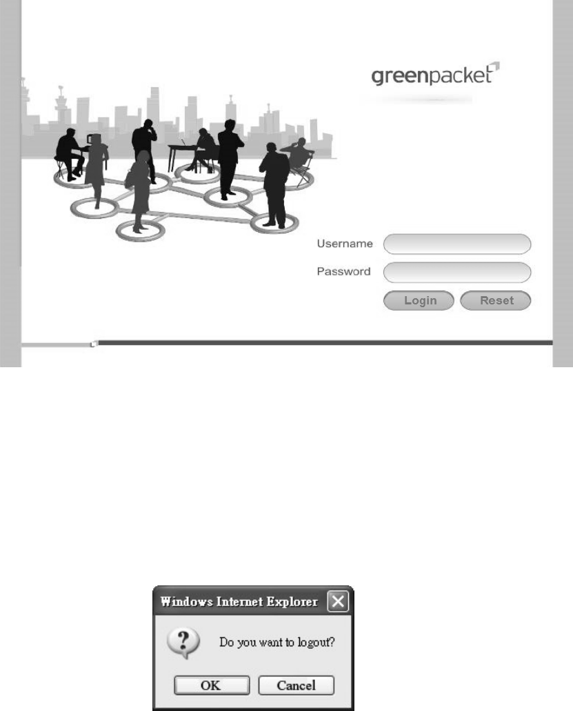
1.1. Connect
Users need to connect to the WiMAX Outdoor CPE platform. It’s assumed that the user has a
fully working WiMAX Out door CPE plat form and properly connected. From the web b rowser
connect to the device, ent ering the IP address of the device; it will prompt user to e nter the
username and password. The default usernames and passwords are as follows.
Username/password
Operator/o perator
gue st/guest
12
Figure 1 Login page
1.2. Logout
The “Log out” wind ow allows users to disconnect from the d evice and exit the W eb-based
Configuration Manager.
Figure 2 Logout
13
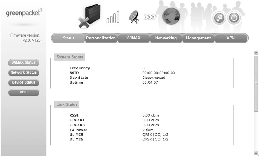
1.3. Status
After user has established a connection, user will see the “Status” window. This window shows
all the status and system information. It gives us er an initial overview of the current st atus of
the device.
Figure 3 Status window
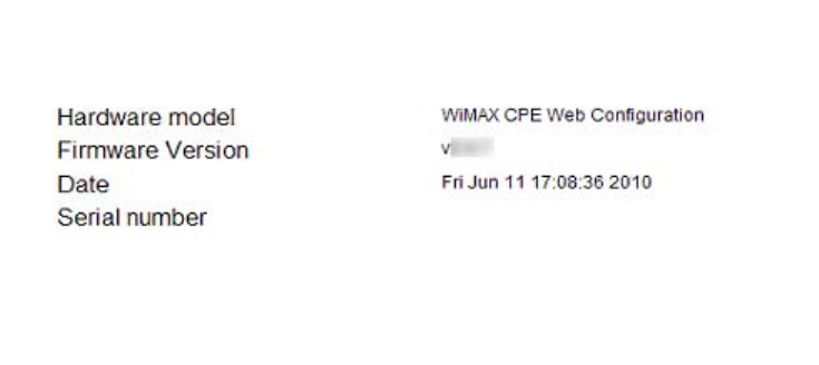
1.4. Device Status
The “Device status” wi ndow displ ays firmwa re versi on informatio n of the WiMAX Out door
CPE.
14
Figure 4 Device status
15
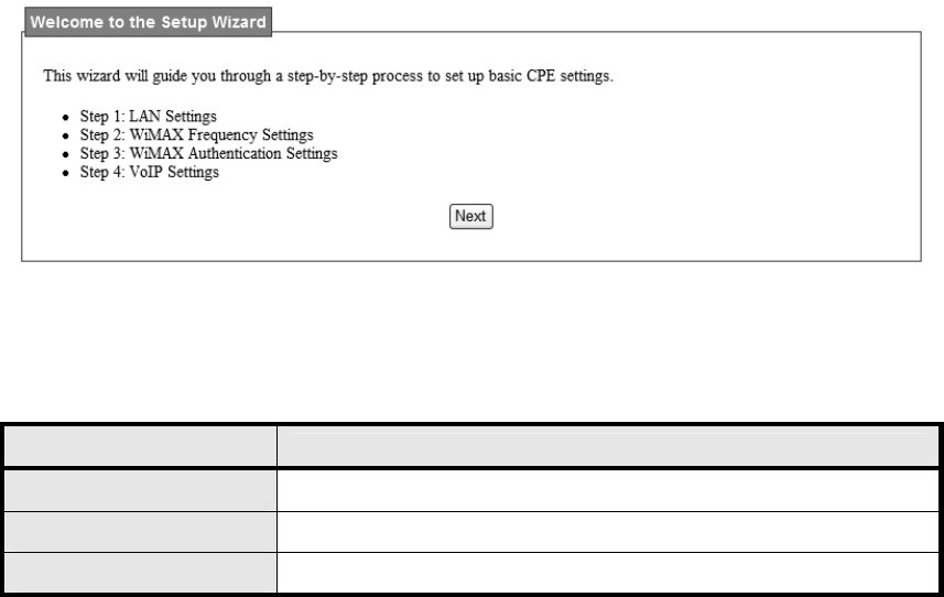
1.5. Setup Wizard
The setup wizard will allow user to quickly configure the basic networking settings on the CPE.
Click the “Setup Wizard” menu item to enter the wizard. The first page will display all the steps
necessary to complete the wizard settings as shown in Figure 5. Later, click the “Next” button
to continue the next steps. The definition of each button shown on web page is defined in the
Table 1.
Figure 5 Setup Wizard
Name Description
Next Continue to the next step
Back Return to the previous step
Save Commit the changes made and save to WiMAX outdoor CPE
Table 1 Button definition shown on Setup Wizard
16
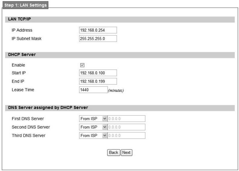
Step 1: LAN Settings. In this step user can configure both IP and DHCP configuration
parameters as shown in Figure 6.
Figure 6 Wizard LAN Settings in Setup Wizard
17
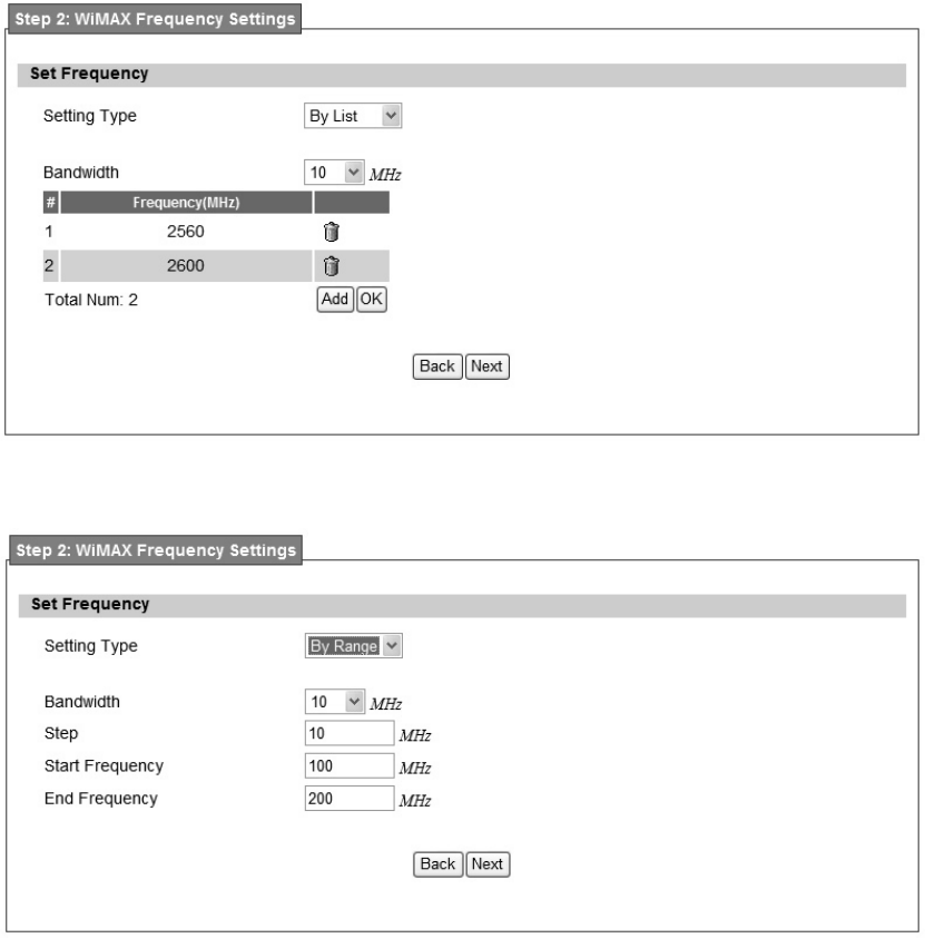
Step2: WiMAX Frequency Settings. This step will qui ckly configure the WiMAX
frequencies. There are two types of configuring the frequencies. User can configure it through
simply entering a frequ ency in the frequen cy list as shown in Fig ure 7 or by gi ving a starting
and ending frequency value and a step size to traverse the range as shown in Figure 8.
Figure 7 WiMAX Frequency Settings By List in Setup Wizard
Figure 8 WiMAX Frequency Settings By Range in Setup Wizard
18
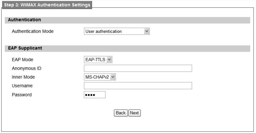
Step 3: WiMAX Authen tication Settings. Thi s will config ure WiMAX Auth entication
settings. There are 4 possible options for “Aut hentication Mode” as No authentication, User
authentication, Device au thentication, and Us er an d device aut hentication. Dep ending o n
which mode user selects, and it will appear different EAP settings for configuration. Except “No
authentication” is selected, user needs to define the EAP supplicant as shown in Figure 9.
Figure 9 WiMAX Authentication Settings in Setup Wizard
Detailed definition of each item in EAP supplicant is listed below.
EAP Mode: WiMAX out door CPE suppor ts EAP-TLS, EAP-TTL S, EAP-SIM, and
EAP-AKA.
Anonymous ID: User needs to fill the Outer ID at this field.
Inner Mode: WiMAX out door CPE supports MS-CHAPv2, MS-CHAP, CHAP, MD5,
and PAP.
Username: User needs to fill username at this field.
Password: User needs to fill password at this field.
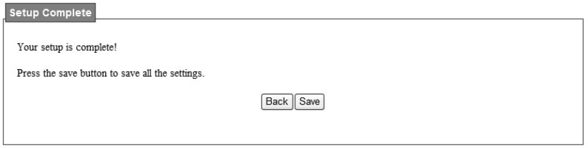
Once the u ser compl etes all the ste ps, user needs to click the “Save” b utton to save th e
settings, or click “Ba ck” button to return to previous step as shown in Figure 10. It will reload
some services and return to the “Home” window after saving all settings.
19
Figure 10 Wizard Save
20
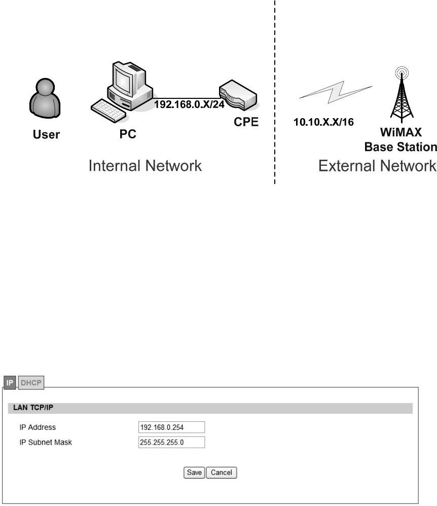
2. Network
Refer to Figure 101, for proper network connection.
Figure 11 Network Topology
2.1. LAN
2.1.1. IP
From the “Network>LAN>IP” window, user can update the LAN information as shown in Figure
12. The definition for each field is shown on Table 2.
Figure 12 Network>LAN>IP

21
Name Description
IP Address IP address of the WiMAX outdoor CPE
IP Subnet Mask Subnet Mask of the WiMAX outdoor CPE
Save Commits the chan ges m ade, and set the LAN IP information ,
some services will be reloaded.
Cancel Reset the fields to the last saved values
Table 2 Field definition for Network>LAN>IP
2.1.2. DHCP
Use the “Net work>LAN>DHCP” t ab to configure the DHCP serve r inform ation. The defa ult
DHCP Server setup is ena bled, and user co uld disable this functi on from setu p as sho wn in
Figure 13. When user disables the DHCP server, it requires to set a static IP address on host
PC for CPE to configure. Please be noted that without the static IP address set properly on the
host PC, user can not open the CPE web page for configuration.
When DHCP se rver i s e nabled, user need s to define the IP pool range f or dyn amically
assigning the IP address. The advant age of usi ng DHCP server is that the addre sses which
are no longer in use will be returned to the IP address pool so that the server can reallocate
them to other machines in the network.
There are three DNS servers the user can configure to assign an IP address. Static DHCP will
assign an IP address on the LAN to a specific device based on its MAC address. The definition
for each field is shown on Table 3.
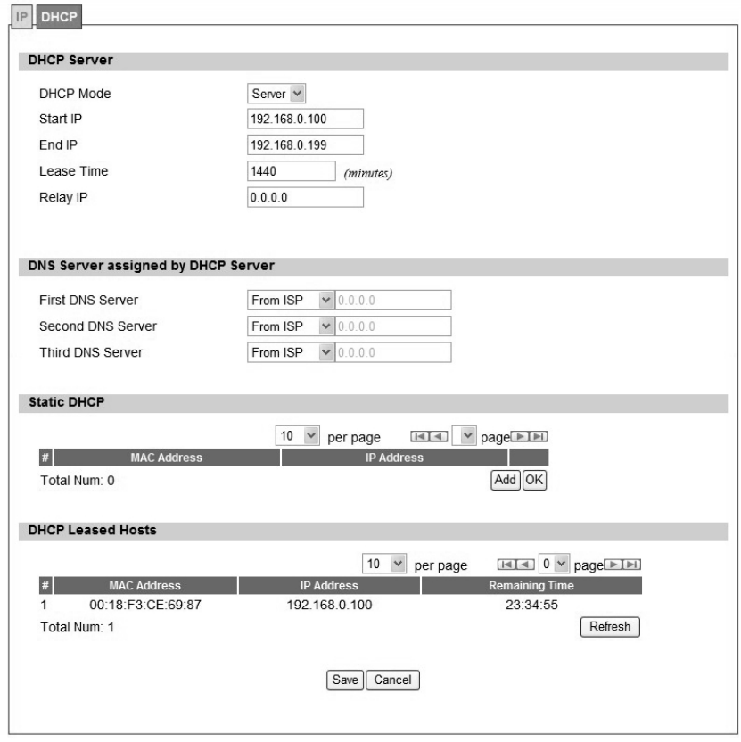
22
Figure 13 Network>LAN>DHCP

23
Name Description
Enable
If the enable box is ch ecked for D HCP server, the DHCP server
will assig n IP addre ss to it s clie nt with the sp ecified IP addre ss
range.
Start IP Starting IP address range
End IP Ending IP address range
Lease Time
The lea se time is a cont rolled time p eriod, allo wing the DHCP
server to reclaim (and then reallocate) IP addresses that are not
renewed (dynamic re -use of IP ad dresses). Le ase tim e i s
measured in minutes in the Configuration Manager.
First DNS Server
Second DNS Server
Third DNS Server
User can sp ecify three DNS serve r and select how the DNS
Server is assigned. There are three options for assigning the DNS
server.
From ISP
User Defined
Non e
If user sel ects “None”, then the DH CP server will no t give clients
the DNS se rver inform ation. If a ll the three DNS servers setting
are set to “Non e”, then the DHCP server will u se the LAN IP
address as the DNS server information for the clients. If the user
chooses “User Defined” and leaves the IP address as “0.0.0.0” it
will change the field to “None”.
Add Click on the “Add” button to enter a static leased IP address. Enter
the MAC address of the Ethernet device and enter the IP address.
OK Click the “OK” button to exit out of edit mode.
Save Commit the changes ma de an d save to WiMAX outdoor CPE,
some services will be reloaded.
Cancel Reset fields to the last saved values.
Table 3 Field definition for Network>LAN>DHCP
2.2. WAN
The wide area netwo rk i s anothe r network that user can conn ect to the internet with the
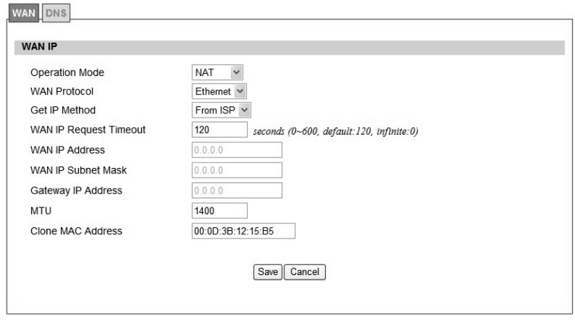
24
WiMAX outdoor CPE.
2.2.1. WAN
In Figure 14, it demonstrates ho w to co nfigure WAN IP on CPE web p age. The definition for
each field is shown on Table 4.
Figure 14 Network>WAN>WAN

25
Name Description
Operation Mode
Select the WAN operation mode
Bridge
Routin g
NA T
WAN Protocol
Select the WAN encapsulation protocol
Ethernet
PPPoE
Get IP Method
Enter the IP method
From ISP
Us er
WAN IP Request Timeout
The time the DHCP client waits to re ceive the IP address from
the BS. If it doesn’t get the IP , it will timeout and the CPE will
disconnect the WiMAX conne ction. T he default value is 12 0
seconds. If u ser ente rs 0, it will wait to receive the IP addre ss
infinitely until it’s stopped by the user.
WAN IP Address If user chooses “User” for IP Method, user should enter the WAN
IP address
WIN IP Subnet Mask If user chooses “User” for IP Method, user should enter the WAN
IP subnet mask.
Gateway IP Address If us er chooses “User” for IP Method, use r shou ld enter IP
gateway address
MTU Enter the MTU
Clone MAC Address Enter the clone MAC address to be used by WAN
PPPoE Setting
User Name The user name to c onnect PPPoE s erver via the selec ted Auth
Protocol
Password The password of the corresponding username
Retype Password Type the “Password” again
Auth Protocol
The a uthentication protocol of t he p eer re quired. S elect which
Authentication protocol to use.
P AP
CHAP
MSCHAPv1
MSCHAPv2
26
Encryption
Encryption Scheme
No
MPPE 40 bits: 40-bit encryption with MPPE
MPPE 128 bits: 128-bit encryption with MPPE
Auto: automatically selected
Idle Timeout Disconnect if the link is idle for the assigned seconds
AC Name The name of the access concentrator to connection to
Save
Commit the changes ma de and save to WiMAX ou tdoor CPE,
after clicking the Save button user will get a message aski ng if
user want s t o reb oot the CPE. Reb oot is ne cessary for the
device to switch to a different profile.
Cancel Reset field to the last saved values
Table 4 Field definition for Network>WAN>WAN
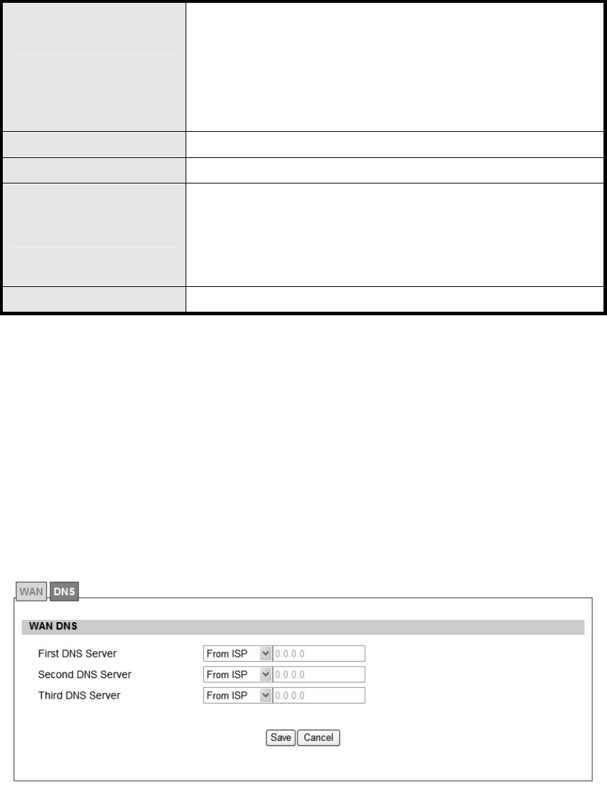
2.2.2. DNS
In Figure 15, it demonstrates how to configure WAN DNS on CPE web page. The definition for
each field is shown on Table 5.
Figure 15 Network>WAN>DNS

27
Name Description
First DNS Server
Enter the WAN DNS information.
User Defined
From ISP
If user sele cts “User Define”, u ser n eeds to ente r a valid IP
address for the DNS server.
Second DNS Server Same as First DNS Server
Third DNS Server Same as First DNS Server
Save Commit the changes made and save to WiMAX outdoor CPE
Cancel Reset fields to the last saved values
Table 5 Field definition for Network>WAN>DNS
28
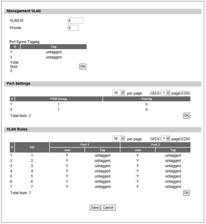
2.3. VLAN
In Figure 16, it demonstrates how to configure VLAN setting on CPE web page. The definition
for each field is shown on Table 6.
Figure 16 Network>VLAN

29
Name Description
Management VLAN
VLAN ID Setting the management VLAN ID
Priority Setting the management Priority
Port Settings
PVID Group Select the VLAN group as the PVID
Priority Setting the port priority
VLAN Rule
VID Setting the VID of this group
Join Add this port into this group
Tag Mark the out-going packets of this port i n this VLAN as tagged or
untagged
Save Commit the changes made and save to the CPE device
Cancel Reset fields to the last saved values
Table 6 Field definition for Network>VLAN
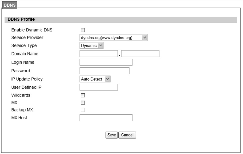
2.4. DDNS
DDNS st ands for Dy namic Dom ain N ame Serv ices. It provides a function to conve rt the
domain name to the unique IP address. With DDNS, users is able to find and connect to CPE
no matter what IP address CPE is curre ntly using, that is, DDNS can map CP E's dynamic IP
address to a static hostname. The best profit of this function allows user to access CPE from
everywhere.
In Figure 17, it demonst rates how to confi gure DDNS on CPE web page. The definition for
each field is shown on Table 7.
30
Figure 17 Network>DDNS

31
Name Description
Enable Dynamic DNS Click the check box to enable dynamic DNS
Service Provider Enter the URL of the Service Provider
Service Type*
Enter the service type (DYNDNS only)
Dynami c
St atic
Cu stom
Domain Name Enter the domain name
Login Name Enter the username
Password Enter the password
IP Update Policy
Select the Policy to be used
Auto Detect
WA N IP
User Defined
User Defined IP If user sele cts “User Defined” as the IP policy, user has to ente r
the IP address.
Wildcards*
Allow hostname to use wildcards such as “* ”. It will allow
“*host.dyndns.org” to be aliased to th e sa me IP address a s
“host.hyndns.org”
MX* Enable mail routing
Back MX* Enable Second mail routing
MX Host* Host that mail will be routed to
Save Commit the changes made and save to WiMAX outdoor CPE
Cancel Reset fields to the last saved values
Note: * Supported by DYNDNS service provider.
Table 7 Field definition for Network>DDNS
32
3. Advanced Setting
The “Advanced Settings” window will allow user to set rules for incoming and outgoing traffic.
3.1. NAT
Network Add ress Translation (NA T) i s the process of modif ying the net work address
information o f the host in a p acket whil e in transit, so that it ca n be rem apped to a given
address space in another network. For example, the source address of a packet in a network
is changed to a different IP address known within another network.
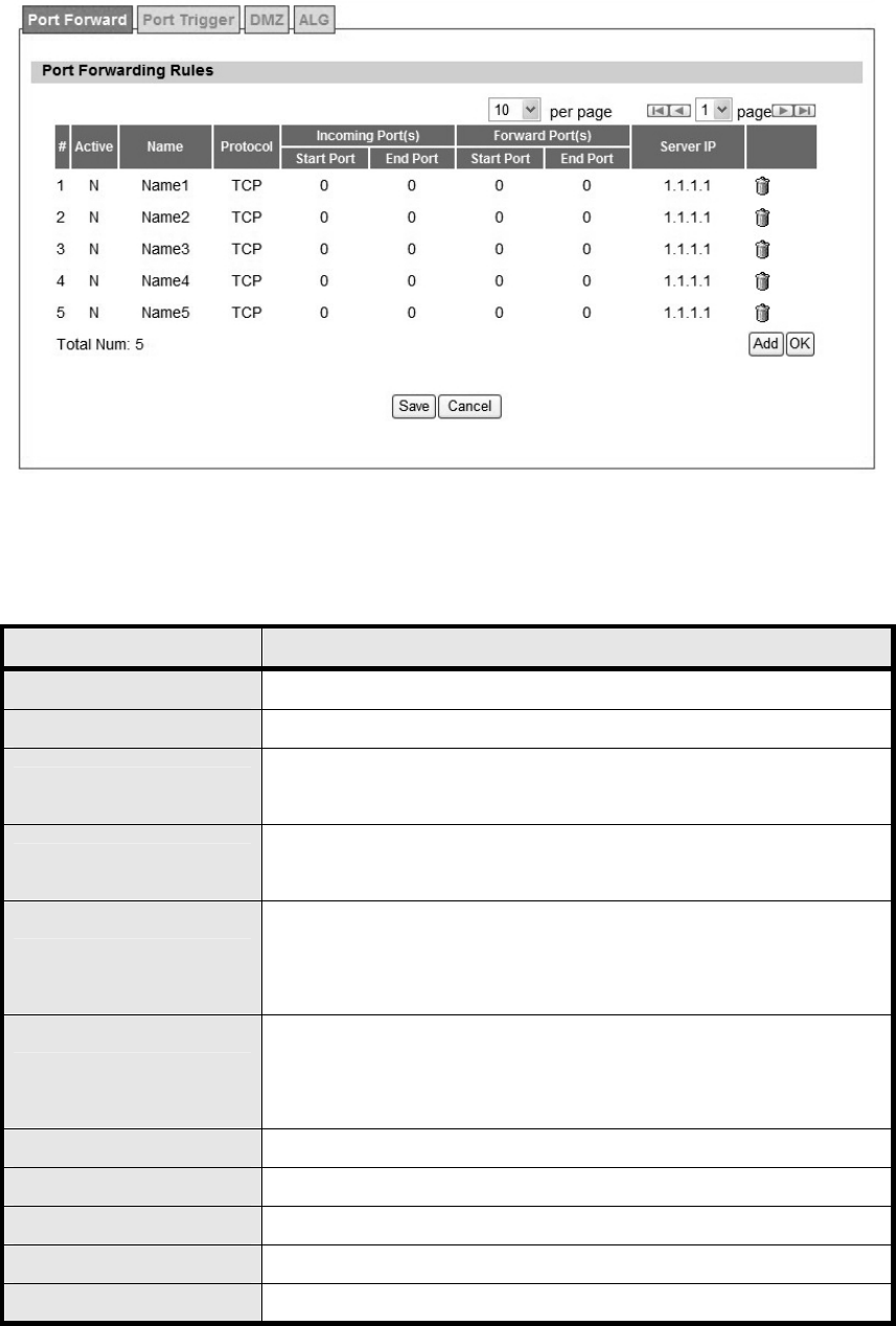
3.1.1. Port Forward
Port forwarding, as the literal meaning, is the act of forwarding the data from WAN side to the
particular port of the private IP. This function can allow remote computers to reach a port on a
private IP address within a private LAN. In the following, it will introduce how to setup for Port
Forward. First, user needs to click the “Add” button and then select which forward type, TCP or
UDP or TCP/UDP, is p referred to trig ger the special application as shown in Figure 18. User
needs to assign some specific port for the WAN IP to be forwarded to the defined LAN IP and
port, and then click the “Save” button to add a Port Forward rule. The definition for each field is
shown on Table 8.
33
Figure 18 Advanced>NAT>Port Forward
Name Description
Activate Check the box to activate the “Port Forward” rule
Name Name of the Port Forward rule
Protocol User ne eds to define the desired protocol for rul e. A vailable
options are: TCP, UDP, or TCP/UDP
Incoming Port(s) User nee ds to define inco ming port ra nge for Port Forwardin g
rule.
Forward Port(s)
User needs to define to which port range will be translated for Port
Forwarding rule. The p acket will be forwarded to one of these
ports if it matches the rule.
Server IP
User ne eds to define whi ch IP address will be translated to if it
matches the Port Forwarding rule. The packet will be forwarded to
this IP address if it matches the rule.
Trash Delete the Port Forward rule
Add Click the “Add” button to create a new Port Forward rule
OK Click the “OK” button to exit table edit mode
Save Commit the changes made and save to the CPE
Cancel Reset field to the last saved values.
Table 8 Field definition for Advanced>NAT>Port Forward
34
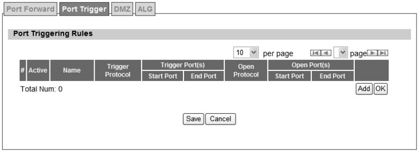
3.1.2. Port Trigger
The “Advanced>NAT>Port Trigger” tab allows user to configure Port Trigger rules. Port Trigger
is a way to automate port forwarding in which outbound traffic on predetermined ports (‘trigger
port’) causes inboun d traf fic to spe cific incomi ng po rts to be dyn amically forwarde d to the
initiating host, while the outbound ports are in use. This allows users behind WiMAX outdoor
CPE on the LAN to provide se rvices t hat woul d no rmally re quire the com puter to have IP
address on the LAN. Port triggering triggers an open incoming port (‘open port’) when a client
on the local network makes an outgoing connection on a predetermined port or range of ports.
The definition for each field is shown on Table 9.
Figure 19 Advanced>NAT>Port Trigger

35
Name Description
Activate Check the box to activate the Port Trigger rule
Name Name of the Port Trigger rule
Protocol It defines which protocol the outgoing packet used will trigger th e
rule. Available options are TCP, UDP or TCP/UDP
Trigger Port(s) It defines which port range the outgoing packet will trigger the rule.
User needs to enter the starting and ending port range
Open Protocol It defines wh ich protocol will be open ed if the rule had bee n
triggered. Available options are TCP, UDP or TCP/UDP
Trash Delete the Port Trigger rule
Add Click the “Add” button to enter a Port Trigger rule
OK Click the “OK” button to exit, table edit mode.
Save Commit the changes made and save to the CPE
Cancel Reset fields to the last saved vaules
Table 9 Field definition for Advanced>NAT>Port Trigger
36
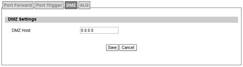
3.1.3. DMZ
DMZ stands for Demilitarized Zone. It is a phy sical or logi cal sub-network that contains and
exposes an organization's external services to a larger un-trusted network, usually the Internet.
The term is normally referred to as a DMZ by IT professionals. It is sometimes referred to as a
Perimeter Ne twork. The p urpose of a DMZ is to add an additio nal layer of se curity to an
organization's LAN; an external attacker only has access to equipment in the DMZ, rather than
any other part of the network.
The “Advanced>NAT>DMZ” tab allows user to configure a DMZ h ost IP address as shown in
Figure 20. In DMZ Setting s, user needs to enter the IP address of the DMZ h ost. The “Save”
button will save the changes to WiMAX outdoor CPE and the “Cancel” button will reset the field
to last saved value. It will disable DMZ host when entering “0.0.0.0”.
Figure 20 Advanced>NAT>DMZ
37
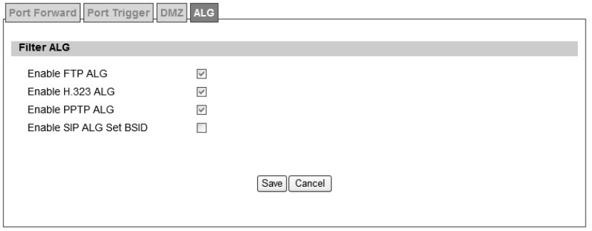
3.1.4. ALG
There a re th ree AL Gs th at use r can enable from “Advanced>NAT>ALG” t ab. ALG allo ws
legitimate ap plication traf fic to p ass throu gh the WiMAX out door CPE that would have
otherwise re stricted. Wit hout ALG s, some application may n ot work well beca use of
NAT/firewall settings. User could click on the check box to enable ALGs.
Note: If user is using any of these types of application protocols user needs to enable them in
the ALG settings.
FTP ALG
H.323 ALG
PPTP ALG
Enable SIP ALG set BSID
Figure 21 Advanced>NAT>ALG
38
3.2. Firewall
In networking, firewalls a re used to blo ck un-wanted traffic or prevent fr om DDOS att acks. It
will prevent unauthorized devices to enter a trusted network.
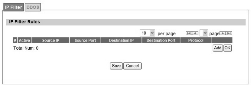
3.2.1. IP Filter
The IP filter rules will drop or discard traffic that the filter criteria. User can define IP filter rules
as shown in Figure 22. The definition for each field is shown on Table 10.
Figure 22 Advanced>Firewall>IP Filter

39
Name Description
Add Click the "Add" button to create a new IP Filter rule
OK Click the "OK" button will exit the table edit mode
Active Check the box to activate the IP Filter rule
Source IP Source IP to filter on. It can be in one of the following formats:
IP address (ex. 192.168.0.222)
Subnet (ex. 192.168.1.0/24)
IP range (ex. 192.168.0.150~192.168.0.160)
0.0.0.0/0 means any
Source Port Source Port to filter on. It can be one of the following formats:
Port number (ex. 8080)
Port Range (ex. 1024~2048)
Destination IP Destination IP to filter on. It can be in one of the following formats:
IP address (ex. 192.168.0.222)
Subnet (ex. 192.168.1.0/24)
IP range (ex. 192.168.0.150~192.168.0.160)
0.0.0.0/0 means any
Destination Port Destination port to filter on. It can be one of the following formats:
Port number (ex. 8080)
Port Range (ex. 1024~2048)
Protocol Protocol to filter on
Trash Delete the IP Filter rule
Save Commit the changes made and save to WiMAX outdoor CPE
Cancel Reset fields to the last saved values
Table 10 Field definition for Advanced> Firewall>IP Filter
40
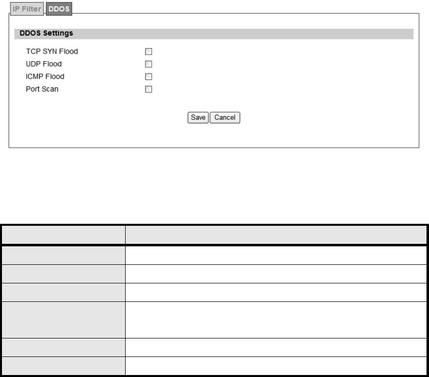
3.2.2. DOS
Before taking about the DDOS service, it will introduce DDOS Attack first. DDOS attack stands
for denial-of-service attack (DoS attack) or distributed denial-of-service attack. It is an attempt
to make a computer resource unavailable to its intended users. One common method of attack
involves saturating the targeted machine with extern al communications requests, such that it
cannot re spond to legitim ate traf fic, or res ponds so slo wly as to be ren dered ef fectively
unavailable. DDOS se rvice here is used to prevent DDOS At tack, and it provides T CP SYN
Flood, UDP Flood, ICMP Flood, and Port Scan for selection. Th e definition for each field is
shown on Table 11.
Figure 23 Advanced>Firewall>DDOS
Name Description
TCP SYN Flood It will prevent SYN flood from WAN or LAN
UDP Flood It will prevent UDP flood to WiMAX outdoor CPE
ICMP Flood It will prevent ICMP flood from WAN or LAN
Port Scan It will prevent port scanning from WAN and issue an alarm entry in
the system log.
Save Commit the changes made and save to WiMAX outdoor CPE
Cancel Reset fields to the last saved values.
Table 11 Field definition for Advanced> Firewall>DDOS
41
3.3. Route
A route is a path in a network, which can direct the flow of network traffic.
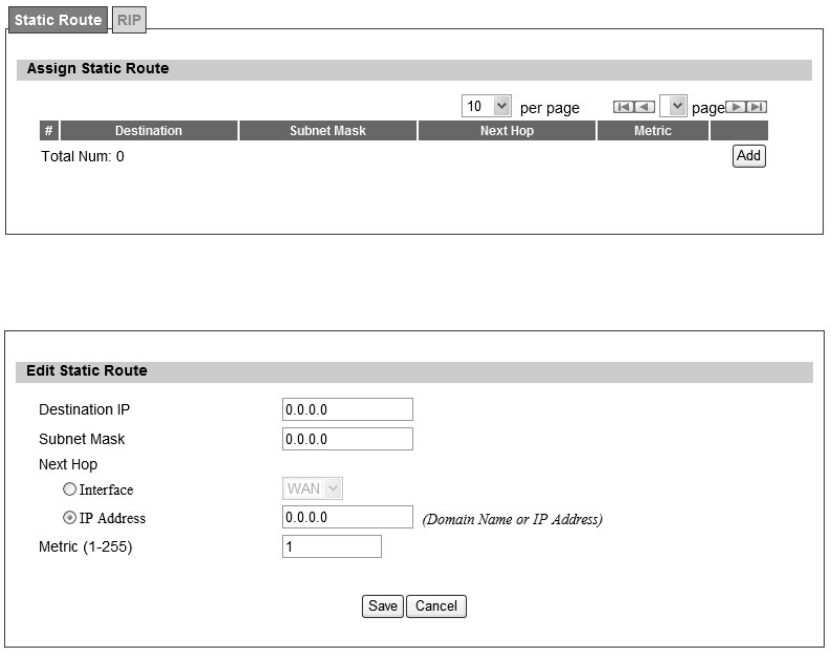
3.3.1. Static Route
The static route is a ha rd coded p ath in the router that sp ecifies how it will get to a cert ain
subnet by using a defined path. User could manually add routes to routing table as shown in
Figure 24 and Figure 25. The definition for each field is shown on Table 12.
Figure 24 Advanced>Route>Static Route
Figure 25 Advanced>Route>Static Route>Add

42
Name Description
Destination IP Enter the Destination IP address user would like to reach
Subnet Mask Enter the subnet mask.
Next Hop
Select where the next hop will be.
WAN or LAN interface directly
IP Address
Metric Enter the metric value, “cost” of transmission for routing purposes
Trash Will remove the selected route
Add Will enter in edit mode to add a static route
Save Commit the changes made and save to WiMAX outdoor CPE
Cancel Reset fields to the last saved values
Table 12 Field definition for Advanced>Route>Static Route
43
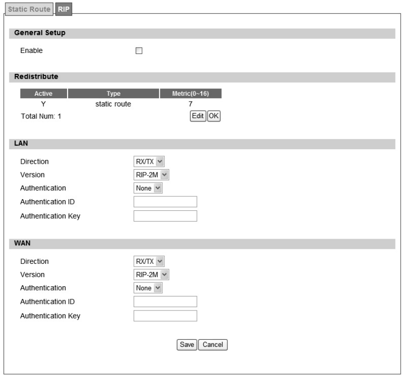
3.3.2. RIP
The Ro uting Information Protocol (RI P) is a dy namic ro uting protocol u sed in local a rea
networks. It allows a router to exchan ge ro uting inf ormation with other route rs. User could
setup the RIP routing rul e as shown in Figure 26. The definitio n for each fiel d is sho wn on
Table 13.
Figure 26 Advanced>Route>RIP

44
Name Description
General Setup | Enable Clicking the enable check box will activate the RIP routing rule
Redistribute Edit
Click the “Edit” button to activate the st atic ro ute or chan ge the
metric value. The static route refers to the static routes defined in
Advanced>Route>Static Route window
Redistribute | OK Click the “OK” button to exit edit table mode
LAN
Direction
Non e
RX
TX
RX/TX
Version
If user selects “RX, TX or RX/TX” for Direction, user will get the
following RIP version options available.
RIP-1
RIP-2B
RIP-2M
Authentication
If user select s RIP-2B or RIP-2M for V ersion, user will get the
following Authentication options.
Non e
Te x t
MD5
Authentication ID If user sele cts “MD5” for Authentication type, user can ente r the
authentication ID and Key
Authentication Key
If user enters “text” for Authentication, user ca n enter a text
authentication key. If user enters “MD5” for Authenti cation type,
user also needs to enter an Authentication ID and Key.
WAN
Direction
Non e
RX
TX
RX/TX
Version
If user selects “RX, TX or RX/TX” for Direction, user will get the
following RIP version options available.
RIP-1
RIP-2B
RIP-2M

45
Name Description
Authentication
If user select s RIP-2B or RIP-2M for V ersion, user will get the
following Authentication options.
Non e
Te x t
MD5
Authentication ID If user sele cts “MD5” for Authentication type, user can ente r the
authentication ID and Key
Authentication Key
If user enters “text” for Authentication, user ca n enter a text
authentication key. If user enters “MD5” for Authenti cation type,
user also needs to enter an Authentication ID and Key.
Save Commit the changes made and save to WiMAX outdoor CPE
Cancel Reset fields to the last saved values
Table 13 Field definition for Advanced>Route>RIP
46
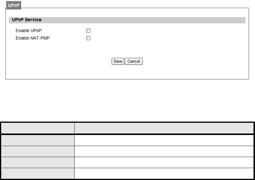
3.4. UPnP
Two methods of simplifying the process of connecting a device to the network are available as
shown in Figure 27. UPnP allows devices to connect seamlessly to networks in the home (data
sharing, communications, and e ntertainment) a nd in co rporate e nvironments for sim plified
installation o f compute r components. NA T Po rt Mappin g Pro tocol (NAP-P MP) allo ws a
computer in a privae network (b ehind a NA T router) to automatically configu re the router to
allow parties outside the private network to contact itself. The definition for each field of UPnP
Setting is shown on Table 14.
3.4.1. UPnP Setting
Figure 27 Advanced UPnP
Name Description
Enable UPnP Check the check box to enable UPnP
Enable NAT-PMP Check the check box to enable NAT-PMP
Save Commit the changes made and save to WiMAX outdoor CPE
Cancel Reset fields to the last saved values
Table 14 Field definition for Advanced> UPnP
47
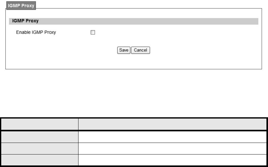
3.5. IGMP Proxy
IGMP proxy enabl es the system to issue IGMP ho st message s on beh alf of host s that th e
system discovered through standard IGMP interface. The system acts as a proxy for its hosts.
3.5.1. IGMP Proxy Setting
Internet Gro up Mana gement Protocol (IGMP) proxy can be used to imple ment multica st
routing. It works by IGMP frame forwarding, and commonly is used when the re is no need to
use more advanced protocol, for exam ple PIM. In WiMAX outdoor WiMAXx CPE, it provides
IGMP Proxy function, and user can enable or disable this function from Web page as shown in
Figure 28.
Figure 28 Advanced>IGMP Proxy
Name Description
Enable IGMP Proxy Check the check box to enable IGMP Proxy
Save Commit the changes made and save to WiMAX outdoor CPE
Cancel Reset field to the last saved values
Table 15 Field definition for Advanced>IGMP Proxy
48
3.5.2. VPN Setting
VPN (Virtual Private Network) is a network that is implemented in an additional software layer
on top of an existing larger network for the purpose of providing a secure extension of a private
network into an insecure network such as the Internet. The links between nodes of a VPN are
formed over logical connections or virtual circuits between hosts of the larger network.
VPNs are often installed by organizations to provide remote access to a secure organizational
network. G enerally, a V PN has a n etwork t opology more complex than a point-to -point
connection. VPNs are also used to mask the IP a ddress of individual comp uters withi n the
Internet in order, for instance, to surf the World Wide Web anonymously or to access location
restricted services, such as Internet television. Here, VPN Settings allow us er to set rules for
VPN, and it supports PPTP, L2TP, and IPsec.
3.6. PPTP
The Point-to-Point T unneling Protocol (PPTP) is a method for i mplementing virtual private
networks. PPTP does not provide c onfidentiality or encryptio n; it relies on the proto col being
tunneled to provide privacy.
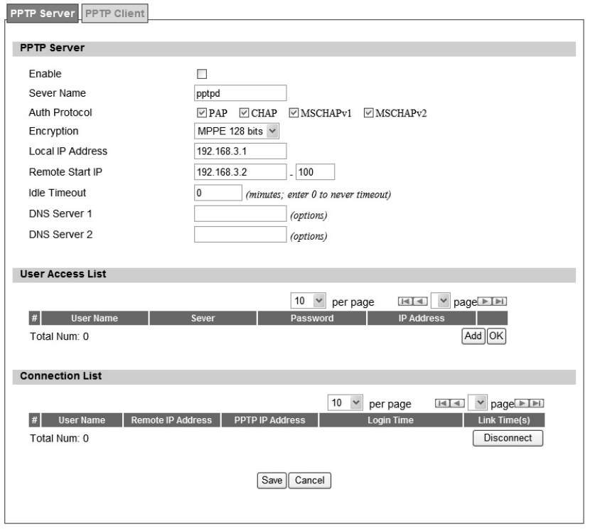
3.6.1. PPTP Server
A PPTP Server (Point -To-Point Tunneling Proto col) allows user t o con nect se curely from a
place (such as the hou se) to a LAN located in another location, such a s the of fice. This wa y
user can use the services provided in the office at the comfort of the house. The definition for
each field of PPTP Server is shown on Table 16.
49
Figure 29 VPN>PPTP>Server

50
Name Description
PPTP Server
Enable Activate PPTP server.
Server Name Offer a service name
Auth Protocol
Require the peer to auth enticate itself before allowing netwo rk
packets to be sent or received. We support the following protocol:
PAP: Password Authentication Protocol
CHAP: Challenge Handshake Authentication Protocol
MSCHAP: Microsoft Chall enge Han dshake Authentication
Protocol
MSCHAPv2: Microsoft Challenge Handshake Authentication
Protocol, Version 2
Encryption
Encryption Scheme:
None
MPPE 40 bits: 40-bit encryption with MPPE
MPPE 128 bits: 128-bit encryption with MPPE
Auto: automatically select
Local IP Address The IP of router
Remote Start IP As sessions are established, IP addresses are assig ned starting
from “Remote Start IP”
Idle Timeout Disconnect if the link is idle for the assigned seconds
DNS Server 1 The primary DNS (Domain Name Server) addresses to clients
DNS Server 2 The secondary DNS (Domain Name Server) addresses to clients
User Access List
User name User ID to connect PPTP server via the selected Auth Protocol
Server Server protocol type
Password Password to connect PPTP server via the selected Auth Protocol
IP address IP address of the connected client
Connection List
User name The user name of the connection
Remote IP address The peer address of the connection
PPTP IP address The assigned IP address of PPTP
Login Time The time of the connection created
Link Time(s) Timer from the connected time
Save Commit the changes made and save to the CPE
Cancel Reset fields to the last saved values
51
Table 16 Field definition for VPN>PPTP>Server
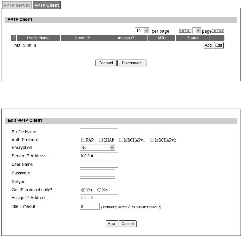
3.6.2. PPTP Client
User could setup PPTP Client as sh own in Fi gure 30 and Figu re 31. The definition for each
field of PPTP Client is shown on Table 17.
Figure 30 VPN>PPTP>Client
Figure 31 VPN>PPTP>Client>Add

52
Name Description
PPTP Client
Add Add a new connection setting
Edit Edit the existed connection setting
Edit PPTP Client
Profile Name The name for this connection setting
Auth Protocol
The Authe ntication protocol of t he p eer requi red. Select which
Authentication protocol to use.
P AP
CHAP
MSCHAPv1
MSCHAPv2
Encryption Enc ryption scheme
Server IP Address The IP address of PPTP server
Username The use r ID to conne ct PPTP server via the s elected Auth
Protocol
Password The password of the corresponding user ID
Retype Type the “Password” again
Get IP automatically? Obtain the dynamic IP address, assigned by the PPTP server
Assign IP Address Assign the static IP address for this connection setting
Idle Timeout Disconnect if the link is idle for the assigned seconds
Save Commit the changes made and save to WiMAX outdoor CPE
Cancel Reset fields to the last saved values
Table 17 Field definition for VPN>PPTP>Client
53
3.6.3. L2TP
In com puter networking, L ayer 2 Tunneling Prot ocol (L2TP) is a tunneli ng p rotocol used to
support virtual private networks (VPNs). It does not provide any encryption or confidentiality by
itself. It relies on an encryption protocol that it passes within the tunnel to provide privacy. The
entire L2TP packet, including payload and L2TP header, is sent within a UDP datagram. It is
common to carry Point-to-Point Protocol (PPP) session within an L2TP tunnel. L2TP does not
provide confidentiality or strong aut hentication by it self. IPsec is of ten used to secu re L2 TP
packets by providing confidentiality, authentication and integrity.
Above is based on information from Wikipedia (http://en.wikipedia.org/wiki/Layer_2_Tunneling_Protocol)
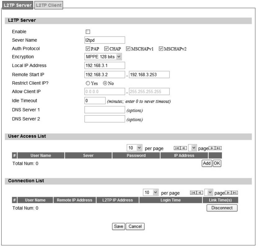
3.6.4. L2TP Server
User can setup WiMAX outdoor CPE from web page as shown in Figure 32. The definition for
each field of PPTP Server is shown on Table 18.
54
Figure 32 VPN>L2TP>Server

55
Name Description
L2TP Server
Enable Check the check box to activate L2TP server.
Server Name Enter a service name
Support Protocol The supported protocol of L2TP messages
Version
ALL: L2TPv2 and L2TPv3
2: L2TPv2 only
3: L2TPv3 only
Auth Protocol
Require the peer to auth enticate itself before allowing netwo rk
packets to b e se nt or received. The followin g p rotocols a re
supported:
PAP: Password Authentication Protocol
CHAP: Challenge Handshake Authentication protocol
MSCHAP: Microsoft Chall enge Han dshake Authentication
Protocol
MSCHAPv2: Microsoft Challenge Handshake Authentication
Protocol, Version 2
Encryption
Encryption Scheme
Non e
MPPE 40 bits: 40-bit encryption with MPPE
MPPE 128 bits: 128-bit encryption with MPPE
Auto: automatically select
Local IP Address The IP of router
Remote Start IP As sessions are established, IP addresses are assig ned starting
from “Remote Start IP”
Restrict Client IP? To restrict client IP address range for the client
Allow Client IP The IP address range for the client
Idle Timeout Disconnect if the link is idle for the given number of seconds
DNS Server 1 The primary DNS (Domain Name Server) addresses to the clients
DNS Server 2 The second ary DNS (Do main Name Server) ad dresses to the
clients
User Access List
User Name User ID to connect L2TP server via the selected Auth Protocol
Server Server Protocol type
Password Password to connect L2TP server via the selected Auth Protocol
IP Address IP address of the connected client

56
Name Description
Connection List
User Name The user name of the connection
Remote IP Address The peer address of the connection
PPTP IP Address The assigned IP address of L2TP
Login Time The time of the connection created
Link Time(s) Elapsed time connected
Save Commit the changes made and save to WiMAX outdoor CPE
Cancel Reset fields to the last saved values
Table 18 Field definition for VPN>L2TP>Server
57
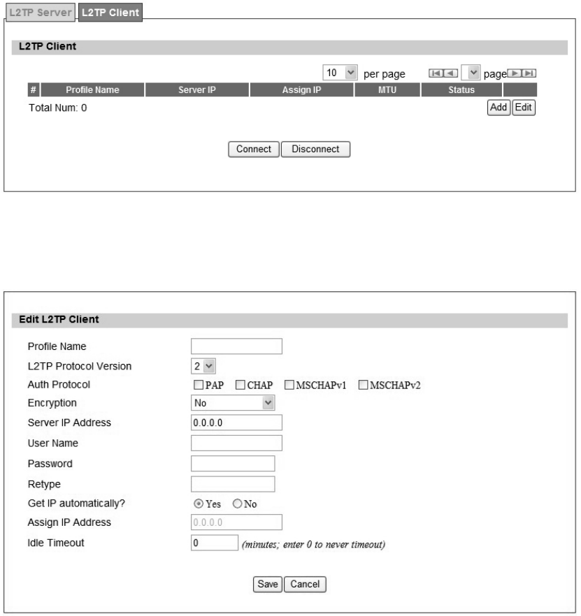
3.6.5. L2TP Client
User could setup PPTP Client as sh own in Fi gure 33 and Figu re 34. The definition for each
field of PPTP Client is shown on Table 19.
Figure 33 VPN>L2TP>Client
Figure 34 VPN>L2TP>Client>Add

58
Name Description
L2TP Client
Add Add a new connection setting
Edit Edit the existed connection setting
Edit L2TP Client
Profile Name The name of this connection setting
L2TP Protocol Version
The me ssage of L2TP p rotocol versi on for thi s connection
setting
2
3
NAT Mode
Enable or disable NAT when connected to PPTP server
Y es: enable
No: disable
Auth Protocol
The Authentication Protocol of the peer required. Select which
Authentication protocol to use.
P AP
CHAP
MSCHAPv1
MSCHAPv2
Encryption Enc ryption Scheme
Server IP Address The IP address of L2TP server
Username The username to conne ct L2TP se rver via the select ed Auth
Protocol
Password The password of the corresponding username
Retype Type the “Password” again
Get IP Automatically? Obtain the dynamic IP address, assigned by the L2TP server
Assign IP Address Assign the static IP address for this connection setting
Idle Timeout Disconnect if the link is idle for the assigned seconds
Save Commit the changes made and save to WiMAX outdoor CPE
Cancel Reset fields to the last saved values
Table 19 Field definition for VPN>L2TP>Client>Add
59
3.7. IPSec
Internet Protocol Security (IPsec) is a n end- to-end secu rity solu tion and operated at the IP
Layer. It provides secure communication between pairs of hosts, pairs of security gateways or
between security gateways and a host. It’s based on a suite of protocols for securing IP traffic
by authenticating and encrypting each IP packet of the data stream.
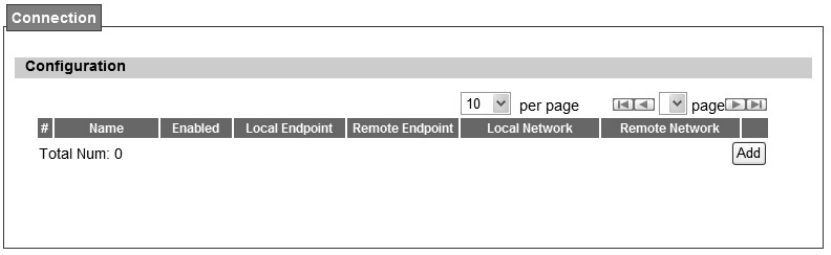
3.7.1. Connection
Figure 35 VPN>IPsec Overview
60
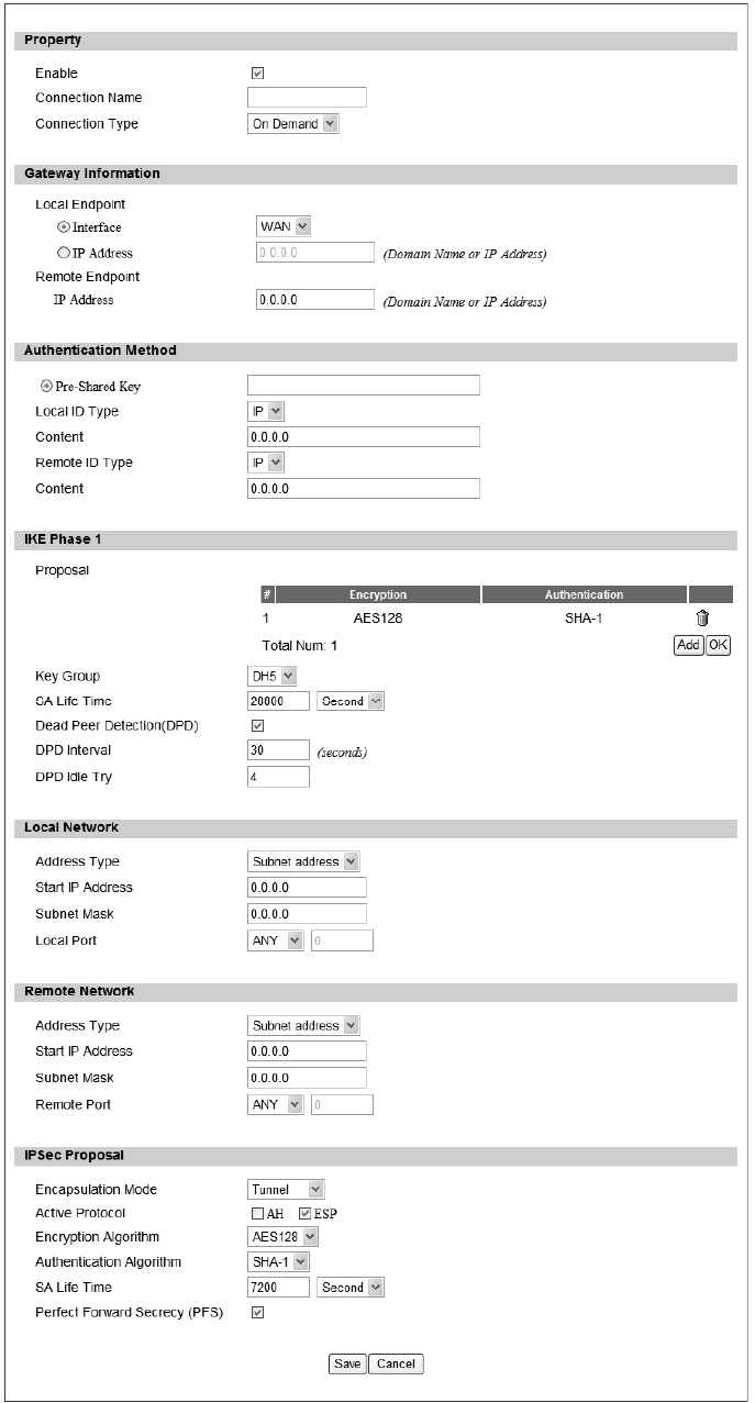
Figure 36 VPN>IPsec>Add

61
Name Description
Add Click the "Add" button to add an IPsec connection rule
Property
Enable Enable IPsec connection.
Connection Name The name of the connection
Connection Type
Select the connection type
Initiator
On Demand
Re sponder
Gateway Information
Local Endpoint Interface The interface of the WiMAX outdoor CPE public-network interface
Local Endpoint IP Address The IP add ress o r Do main Na me of the WiMAX out door CPE
public-network interface
Remote Endpoint IP
Address The IP address or Domain Name of the remote peer.
Authentication Method
Pre-Shared Key The pre-share key that two security gateways use to authenticate
Local ID Type
States ho w the WiMAX out door CPE shoul d be identified for
authentication
IP: The WiMAX out door CPE is identi fied by the assi gned IP fo r
authentication. The default value is 0.0.0.0.
Content The IP address
Remote ID Type
States how the remote peer should be identified for authentication
IP: The remote pee r is identified by the assign ed IP for
authentication. The default value is 0.0.0.0, and this means WiMAX
outdoor CPE will accept any IP.
Content The IP address
IKE Phase 1

62
Name Description
Proposal Add
Press the A dd button to enter an Encryption a nd Authentication
algorithm Cli ck th e tra sh t o rem ove the sele cted algorithm. En cryption
Algorithm:
DES
3DES
AES128
AES192
AES256
Authentication Algorithm:
MD5
SHA-1
Proposal OK Click the OK button to exit the table edit mode
Key Group The DH group used to negotiate the IKE/ISAKMP SA.
SA Life Time The period that the keying channel of a connection (IKE/ISAKM P SA)
should last before being renegotiated.
Dead Peer Detection (DPD) Enable or disable the Dead Peer Detection protocol (RFC 3706)
DPD Interval The time interval when R_U_THERE messages are sent to the peer.
DPD Idle Try
The retry co unter fo r DPD. The tim eout interval i s "DP D inte rval"
multiplied by "DPD Idle Try". After the timeout interval all connections to
the peer are deleted if they are inactive.
Local Network The private subnet behind the WiMAX outdoor CPE.
Address Type
Single Address: The private subnet consisting of one IP address.
Subnet a ddress: The private sub net consisting wi thin the sub net IP
addresses.
Start IP Address The only IP address allowed in the subnet
Subnet Mask The netmask of the subnet (Subnet address)
Local Port
Restrict the traffic selector to a single protocol and/or port.
Any: No restriction
ICMP: Restrict the traffic selector to ICMP protocol.
TCP: Restrict the traffic selector to TCP protocol. If the port number
is 0, all TCP port numbers are accepted.
UDP: Re strict t he t raffic selector to UDP protoco l. If the port
number is 0, all UDP port numbers are accepted.
Remote Network The private subnet behind the remote peer.
Address Type Single Address: The private subnet consisting of one IP address.
Subnet address: The private subnet consisting of subnet IP addresses.

63
Name Description
Start IP Address The only IP address allowed in the subnet
Subnet Mask The netmask of the subnet (Subnet address)
Remote Port
Restrict the traffic selector to a single protocol and/or port.
Any: No restriction
ICMP: Restrict the traffic selector to ICMP protocol.
TCP: Restrict the traffic selector to TCP protocol. If the port number
is 0, all TCP port numbers are accepted.
UDP: Re strict t he t raffic selector to UDP protoco l. If the port
number is 0, all UDP port numbers are accepted.
IPSec Proposal
Encapsulation Mode
The type of the connection:
Tunnel: signifying a host-to-host, host-to-subnet, or subnet-to
subnet tunnel.
Transport: signifying host-to-host transport made.
Active Protocol Whether authentication should be done as part of ESP encryption and/or
separately using the AH protocol.
Encryption Algorithm
NULL
AES128
AES192
AES256
DES
3DES
Authentication Algorithm
MD5
SHA-1
SA Life Time
The time interval a particular instance of a connection (a set of
encryption/authentication key for user packets) should last, from
successful negotiation to expiry.
Perfect Forward Secrecy
(PFS)
Whether Perfect Forward Secrecy of keys is desired on the connection's
keying channel.
Save Commit the changes made and save to the CPE device
Cancel Reset fields to the last saved values.
Table 20 Field definition for VPN>IPsec>Add
64
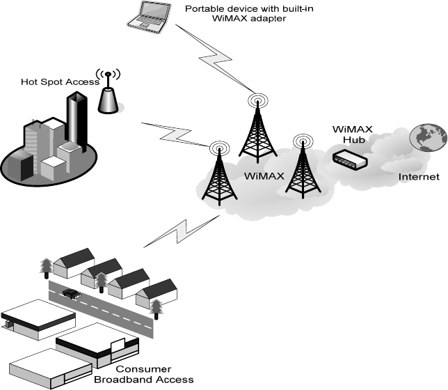
4. WiMAX
This technolo gy is based on the IEEE 802.16 st andard, ena bling the delivery of last mile
wireless broadband access.
Figure 37 Wireless Broadband Access
4.1. Profile
In the profile tab, the user can set WiMAX standard settings, which include how to establish a
connection, frequency information and how to authenticate.
65
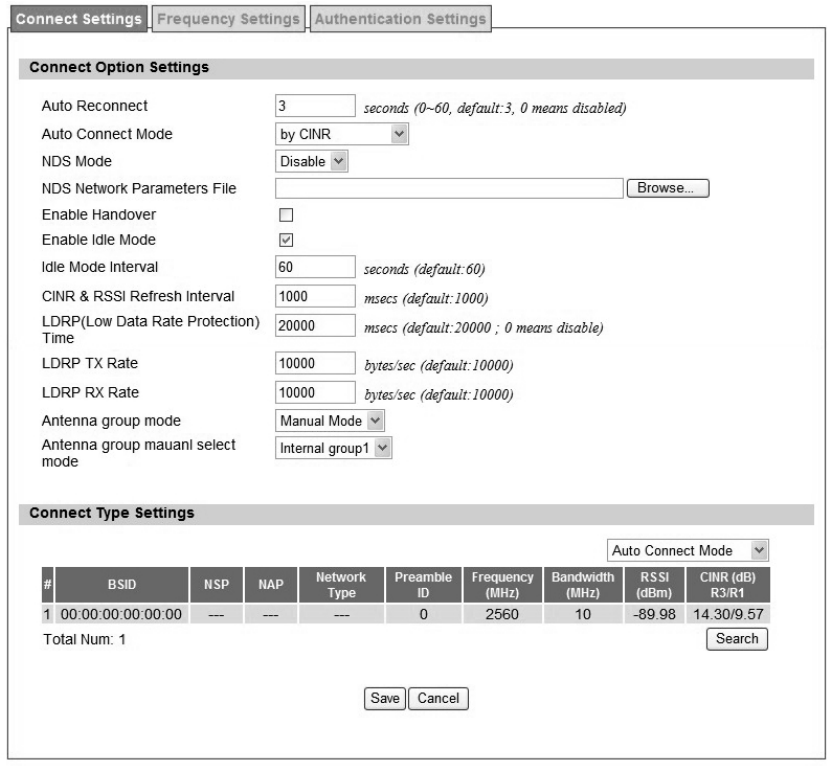
4.1.1. Connect Settings
Figure 38 WiMAX>ProfiIe>Connect Settings

66
Name Description
Connect Options Settings
Auto Reconnect Indicate th e interval in second to “a uto re connect”. 0 mean s
disabled.
Auto Reconnect Mode
Use CINR or RSSI as the crite rion of “Auto Connect Mode”. Note
that “Auto Connect Mode” refer to following “Auto Connect Mode”
in “Connect Mode”.
NDS Mode Enable NDS mode or not. (NDS is still testing)
NDS parameter Upload a file which contains NDS parameter information
Enable Handover Enable handover or not
Enable Idle Mode Enable Idle Mode or not
Idle Mode Interval
Only valid if previous “Enable Idle Mode” set to enable. Interval in
seconds whi ch firmware will trigger Idle Mode after nit packet
traffic.
CINR & RS SI Refre sh
Interval Interval in seconds to update CINR & RSSI after connected
LDRP Time
LDRP (Lo w Data Rate Protection ). When it’s enable, if th e
uplink/downlink data rate is smaller than the LDRP time, the CPE
will send disconnect command to BS.
lDRP TX/RX Rate LDRP uplink/downlink data rate
Antenna Group Mode Auto Mode or Manual Mode
Antenna Ma nual Sele ct
Group Mode
Only valid if previous “Antenna Group Mode” set to Manual Mode.
Valid options:
Internal group 1
Internal group 2
External group
Connect Type Settings
Search Click on the search button to search for available BSID
Connect Mode
Select a connect mode
Auto Connect Mode: It will connect to one of the BSID in the li st,
indiscriminately.
Network Search Mode: User needs to select one of the BSID from
the list, it will use the BSID to co nnect to WiMAX after device i s
reboot.
67
Search Click on the search button to search for available BSID's
Connect Mode
Select a connect mode.
Auto Connect Mode: It will connect to o ne of the BSI D's in
the list, indiscriminately
Network Search Mo de: User ne eds to select one of the
BSID's from the list, it wi ll us e that BSID to conn ect to
WiMAX after device is reboot.
Save Commit the changes made and save to WiMAX outdoor CPE
Cancel Reset fields to the last saved values
Table 21 Field definition for WiMAX>ProfiIe>Connect Settings
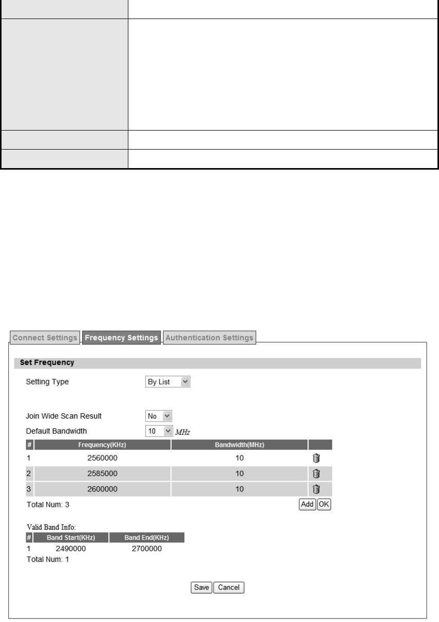
4.1.2. Frequency Settings
The frequency list window will display all the configu red frequencies and thei r bandwidth. To
set additional frequencies, click on the “Add” button.
Figure 39 WiMAX>Profile>Frequency Settings>By List
68
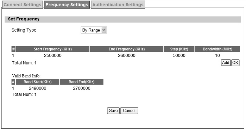
Figure 40 WiMAX>Profile>Frequency Settings>By Range

69
Name Description
Setting Type
There are two display types user can select.
User can choose to display the data by List. If user selects "By
List", user also has the option to add more frequencies.
"By Range" will display the freq uency by rang e a nd the
incremental value. See Figure "Frequency By Range" for more
detail.
Joint Wide Scan Result Yes me ans to app end wide sca n resu lt to the freq uency setting .
Only valid when setting type is “By List”.
Default Bandwidth
Select the default bandwidth to be used in Frequency List
5 MHz
10 MHz
Valid Band Info Valid ba nd in formation. If the fre quencies a ren’t located u sing th e
valid band range, the frequency setting will be rejected.
Add The "Add" button will allow user to enter more frequency lists
OK Click the "OK" button to exit table edit mode
Save Commit the changes made and save to WiMAX outdoor CPE
Cancel Reset fields to the last saved values
Table 22 Field definition for WiMAX>Profile>Frequency Settings>By Range
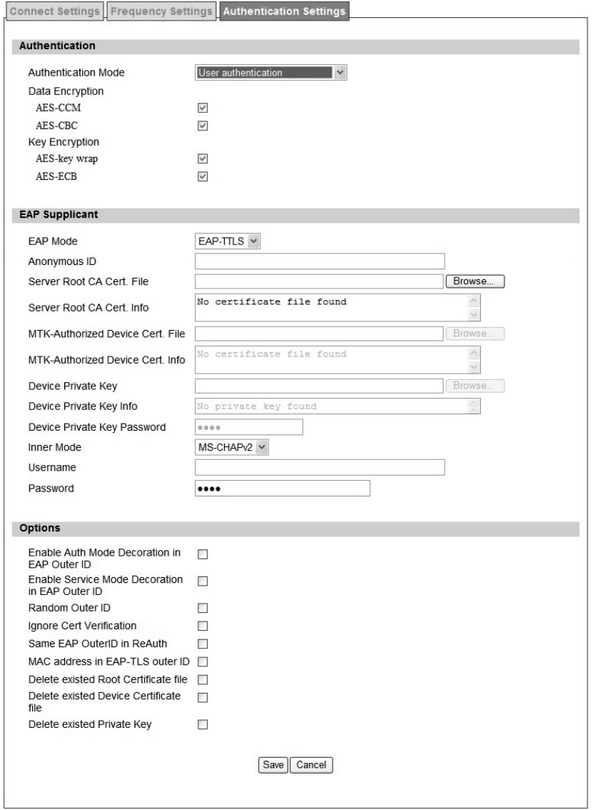
4.1.3. Authentication Settings
Figure 41 WiMAX>ProfiIe>Authenticaton Settings (No Authentication)
70
Figure 42 WiMAX>ProfiIe>Authenticaton Settings (User Authentication)

71
Name Description
Authentication
Authentication Mode The method used in authentication.
Data Encryption AES-CCM Enable MS’ s cap ability of encryptin g/decrypting traf fic by
AES-CCM.
Data Encryption AES-CBC Enable MS' s ca pability of encry pting/decrypting traf fic by
AES-CBC.
Key Encryption AES-key wrap Enable MS's capability of decrypting TEK by AES-Key wrap.
Key Encryption AES-ECB Enable MS's capability of decrypting TEK by AES-ECB.
EAP Supplicant
EAP Mode The EAP method used in authentication
Anonymous ID The identity encoded in EAP Identity Response message
Root CA Certificate The root CA's X.509 certificate.
Client CA Certificate The MS's X.509 certificate.
Private Key The MS' s pri vate key file corre sponding to the publ ic key
enhanced in x.509 certificate
Private Key Password The key used to decrypt the MS’s private key file
Inner Mode The EAP-TTLS inner method
User name The user name used in EAP-TTLS inner method
Password The password used in EAP-TTLS inner method.
Options
Auto Prepend Auth Mode
Enable the MS to automatically decorate “{am=i}” in the EAP
Identity Resp onse me ssage Th e valu e of "i" dep ends on
Authentication Mode field.
Random Outer ID Enable MS t o gene rate 16-bytes random num ber as the
user name in the EAP Identity Response message.
Ignore Cert Verification MS ski ps t o v erify t he BS's ce rtificate receiv ed in t he
EAP-TLS or EAP-TTLS procedure.
Same EAP Outer ID in ReAuth Use the same EAP outer ID when doing re-auth
MAC address in EAP-TLS
outer ID Add MAC address in outer ID when EAP mode is EAP-TLS
Delete existed Device
Certificate file
Delete device certificate file which was uploaded in the field
“MTK-authorized Device Certificate”
Delete existed Private Key Delete d evice private key which wa s uploaded in the field
“Device Private Key”
72
Save Commit the changes made and save to CPE
Cancel Reset fields to the last saved values
Table 23 Field definition for WiMAX>ProfiIe>Authentication Settings
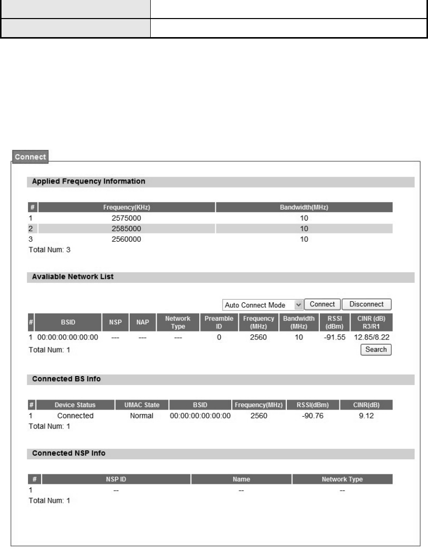
4.2. Connect
Figure 43 WiMAX>Connect>Connect
73
Name Description
Disconnect Click the disconnect button to terminate the connection
Connect Click the connect button to connect to a BSID
Connect Mode
Select a connect mode.
Auto Connect Mode: It will connect to o ne of the BSI D's in
the list indiscriminately
Network Search Mo de: User ne eds to select one of the
BSID's from the list, it wi ll us e that BSID to conn ect to
WiMAX after device is reboot.
Search Click the search button to scan the frequency
Table 24 Field definition for WiMAX>Connect>Connect
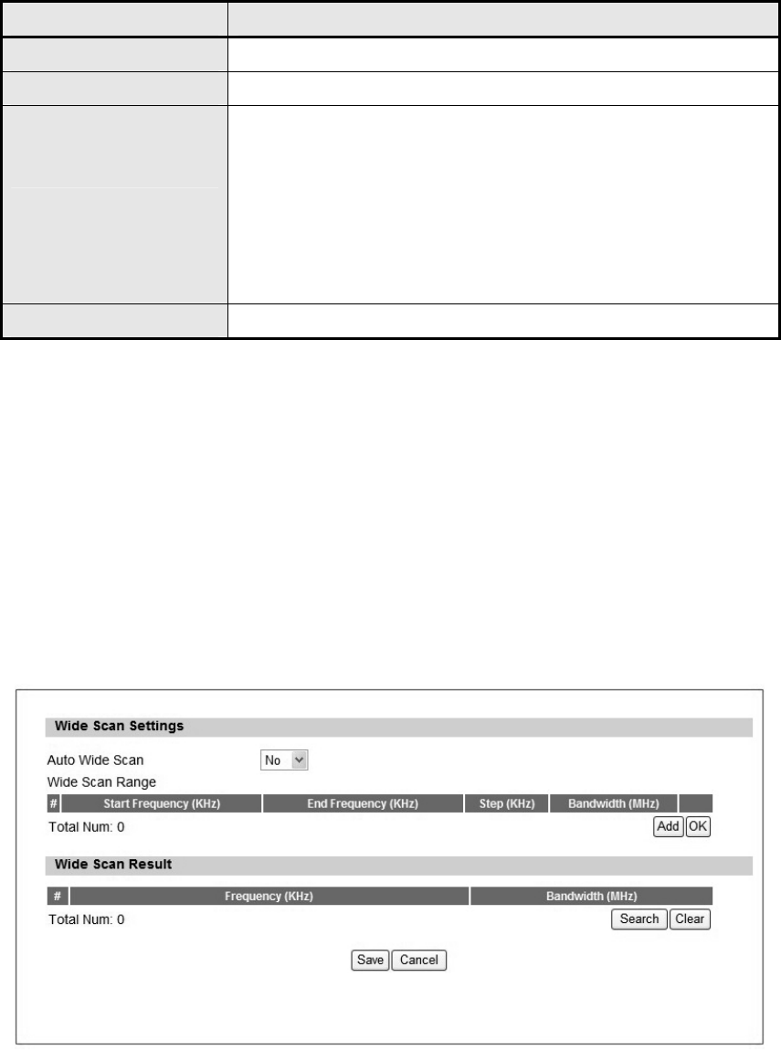
4.3. Wide Scan
The “Wide Scan” function is used for scannin g BS based on scanning rule. Use r can set the
scan rule with defining start, stop frequency, step, and channel bandwidth, and CPE will base
on this rule to scan th e BS as shown in Figure 44. The definitio n for ea ch field is shown on
Table 25.
Figure 44 WiMAX>Wide Scan
74
Name Description
Auto Wide Scan Select “Yes” to do “wide scan” automatically when there are no available BS.
Wide Scan Range
Add/Ok User can specify the wide scan range to reduce search time
Wide Scan Result
Search Show the result of wide scan. Search button can trigger wide scan
Clear Clear button clear current search result
Save/Cancel Save/Can cel current setting
Table 25 Field definition for WiMAX>Wide Scan
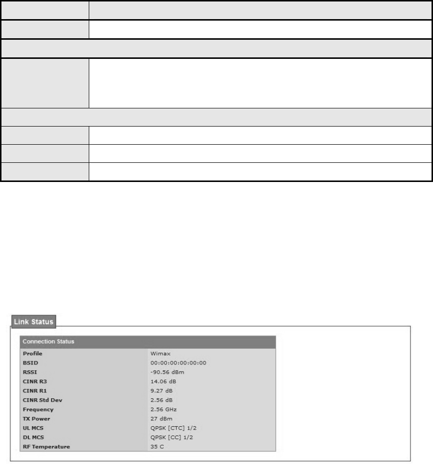
4.4. Link Status
The “Link Status” menu item shows a brief profile of the current WiMAX link.
Figure 45 WiMAX>link Status
75
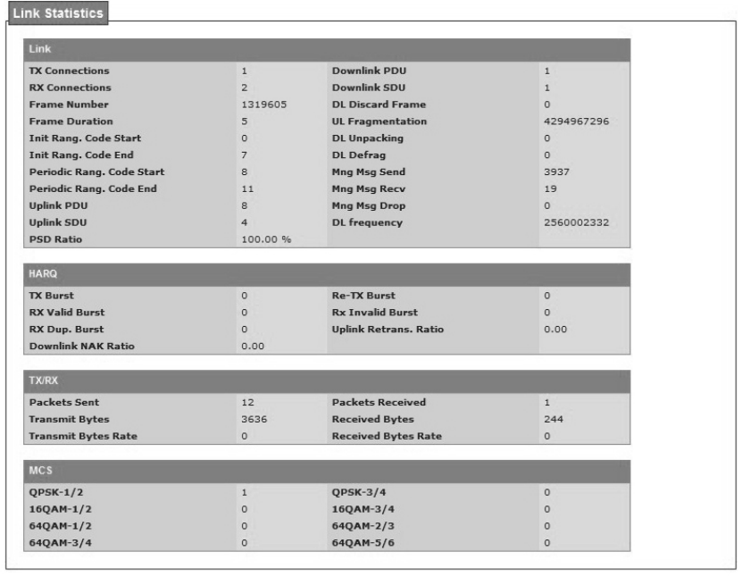
4.5. Link Statistics
Wimax>Link Statistics
The“Link Statistics”menu item will display statistical information in the WiMAX link.
Figure 46 WiMAX Link Statistics
76
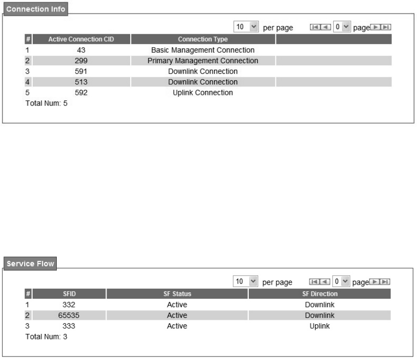
4.6. Connection Info
The connection info window will show the connection ID and its connection type.
Figure 47 WiMAX Connection Info
4.7. Service Flow
The WiMAX service flow window will show the status and direction of each service flow ID.
Figure 48 WiMAX Service Flow
77
5. Administrator
5.1. Remote Control
Remote access is the ability to get access to WiMAX outdoor CPE from a remote computer or
network. WiMAX outdoor CPE supports five different types of remote access protocols.
HTTP allows user to set the port and configure both HTTP and HTTPS protocols.
Telnet typically provides access to a command-line interface on a remote machine.
SSH Sec ure Shell (SSH) is a network pr otocol u sed to allow remote con nections
between two device s usi ng a se cure chan nel. It use s publi c-key cryptog raphy to
authenticate the rem ote entity. An SSH server, by de fault, listens on the st andard TCP
port 22.
SNMP is typically used for network management to monitor network-attached devices for
conditions that warrant admin istrative assi stance or to view and retri eve network
statistical information.
TR-069 using TR-069 the terminals can communicate with he Auto Configuration Servers
(ACS) and establish the configuration automatically.
78
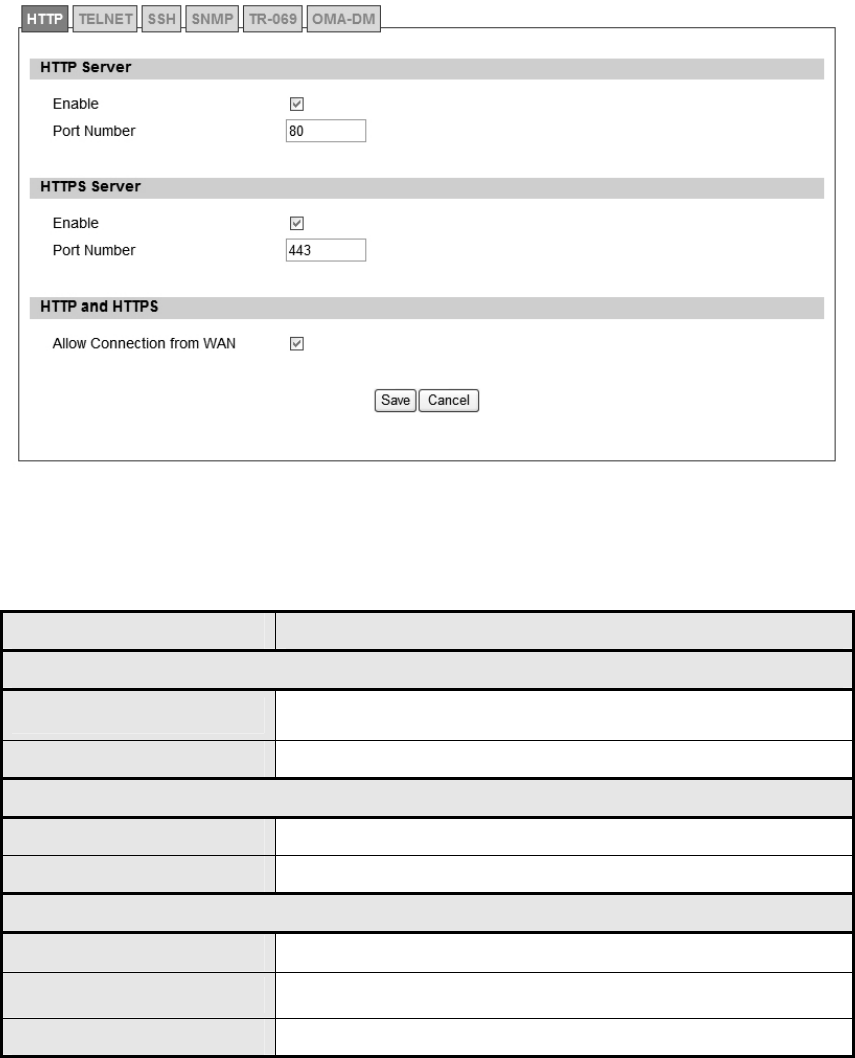
5.1.1. HTTP
Figure 49 Administration>Remote Control>HTTP
Name Description
HTTP Server
Enable Check the box to allow http connections.
Port Number Enter the http port number (default is port 80)
HTTPS Server
Enable Check the box to allow https connections.
Port Number Enter the https port number (default is port 443)
HTTP and HTTPS
Allow Connection from WAN Check the check-box to allow connections from WAN.
Save Commit the changes made and save to WiMAX outdoor CPE.
Cancel Reset fields to the last saved values.
Table 26 Field definition for Administration>Remote Control>HTTP
79
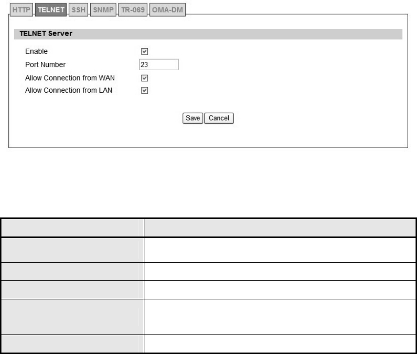
5.1.2. TELNET
Figure 50 Administration>Remote Control>Telnet
Name Description
Enable Check the box to allow Telnet connections.
Port Number Enter the Telent port number (default is port 23)
Allow Connection from WAN Check the check-box to allow connections from WAN.
Save Commit the changes ma de and save to WiMAX outdoo r
CPE.
Cancel Reset fields to the last saved values.
Table 27 Field definition for Administration>Remote Control>Telnet
80
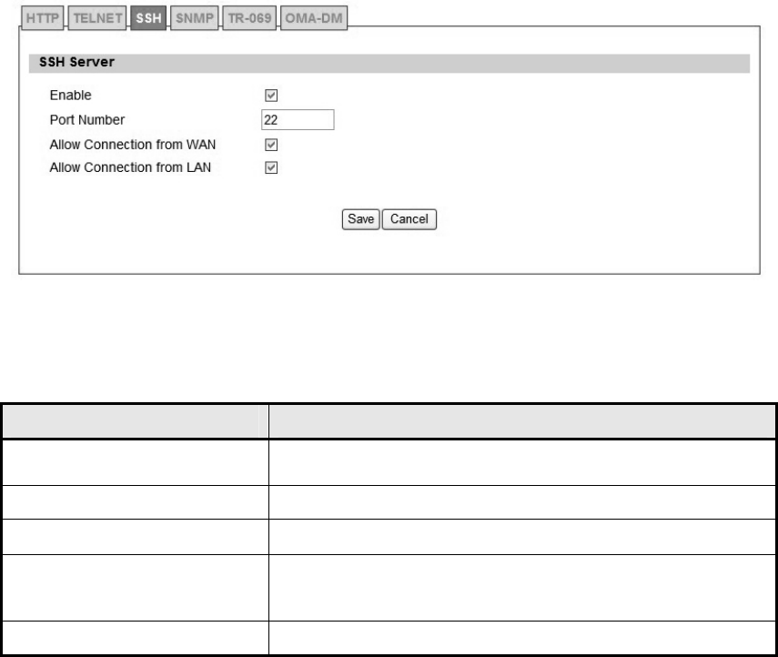
5.1.3. SSH
Figure 51 Administration>Remote Control>SSH
Name Description
Enable Check the box to allow SSH connections.
Port Number Enter the SSH port (default is port 22)
Allow Connection from WAN Check the check-box to allow connections from WAN.
Save Commit the changes ma de and save to WiMAX outdoo r
CPE.
Cancel Reset fields to the last saved values.
Table 28 Field definition for Administration>Remote Control>SSH
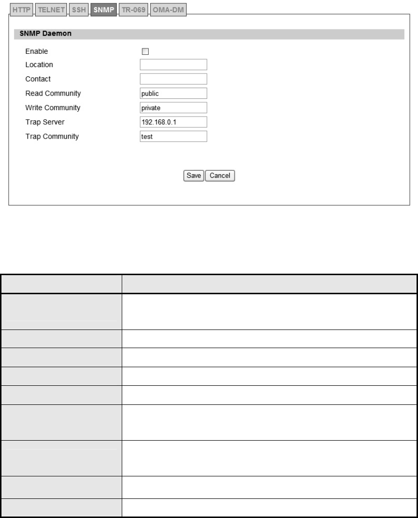
81
5.1.4. SNMP
Figure 52 Administration>Remote Control>SNMP
Name Description
Enable Checking the enable button will allow SNMP applications to query
and set some of the SNMP variables.
Location Enter the Location SNMP string variable.
Contact Enter the Contact SNMP string variable.
Read Community Enter Read community string to query SNMP data.
Write Community Enter Write community string to query SNMP variables.
Trap Server Enter the I P Addre ss of trap server where yo u wa nt tra p
notifications to be sent to.
Trap community Enter the T rap community to act as a password for sending trap
notifications to the target SNMP manager.
Save Commit the changes made and save to WiMAX outdoor CPE.
Cancel Reset fields to the last saved values.
Table 29 Field definition for Administration>Remote Control>SNMP
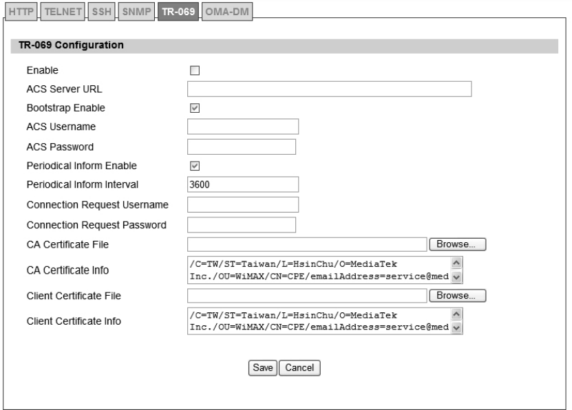
82
5.1.5. TR-069
Using TR-069 the terminals can communicate with the Auto Configuration Servers (ACS) and
establish the configuration automatically. It’s the current standard for activation of terminals in
the DSL broadband market.
Figure 53 Administration>Remote Control>TR-069

83
Name Description
Enable To enable or disabl e the TR- 069 activity on the WiMAX outdoo r
CPE.
ACS Server URL The ACS URL for the WiMAX outdoor CPE to connect to.
ACS Username The usernam e for the Wi MAX outdoor CPE when connected to
ACS.
ACS Password The pa ssword for the Wi MAX outdoor CPE when connected to
ACS.
Periodical Inform Enable To enable or disable the periodical inform to ACS for the WiMAX
outdoor CPE.
Periodical Inform Interval The interval between two periodical inform.
Connection Request
Username
Enter the username for the ACS to perform connection request to
WiMAX outdoor CPE.
Connection Request
Password
Enter the password for the ACS to perform connection request to
WiMAX outdoor CPE.
CA Certificate File The CA certi ficate file is use d to ident ify the certificate of ACS
when D-230 communicated ACS with HTTPS URL.
CA Certificate Info Displays the subject field of the CA Certificate.
CLIENT Certificate File The CLIENT certificate file is used wh en WiMAX outdoor CPE
communicates with HTTPS URL.
CLIENT Certificate Info Displays the subject field of the CLIENT Certificate.
Save Commit the changes made and save to WiMAX outdoor CPE.
Cancel Reset fields to the last saved values.
Table 30 Field definition for Administration>Remote Control>TR-069
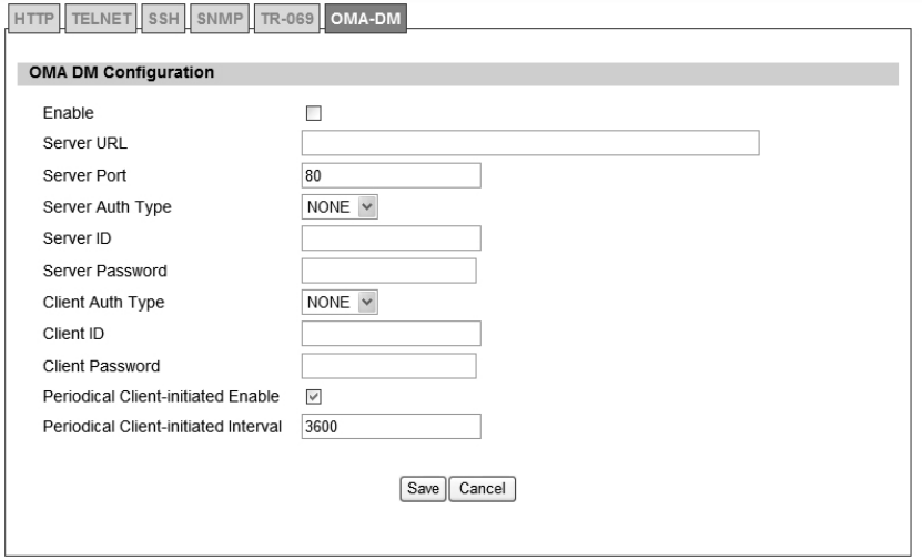
84
5.1.6. OMA-DM
Using OMA DM the termi nals can communicate with the OMA DM Server a nd establish the
configuration automatically. It’s the curre nt standard for activation of terminals in OMA (Open
Mobile Alliance).
Figure 54 Administration>Remote Control>OMA-DM

85
Name Description
Enable To enable or disable the OMA-DM activity of the WiMAX outdoor
CPE.
Server URL The DM Server URL for the WiMAX outdoor CPE to connect to.
Server Port The DM Server Port for the WiMAX outdoor CPE to connect to.
Server Auth Type The DM Server authentication type.
Server ID The Server ID for the WiMAX outdoor CPE when con nected to
DM Server.
Server Password The Server passwo rd for the WiMAX outdoor CPE whe n
connected to DM Server.
Client Auth Type The DM Client authentication type.
Client ID The Client ID for the WiMAX outdoor CPE when connected to DM
Server.
Client Password The Client password for the WiMAX outdoor CPE whe n
connected to DM Server.
Periodical Client-
initiated Enable
To enable or disable the periodical client-initiated session to DM
server for the WiMAX outdoor CPE.
Periodical Client-
initiated Interval The interval between two periodical client-initiated session.
Save Commit the changes made and save to WiMAX outdoor CPE.
Cancel Reset fields to the last saved values.
Table 31 Field definition for Administration>Remote Control>OMA-DM
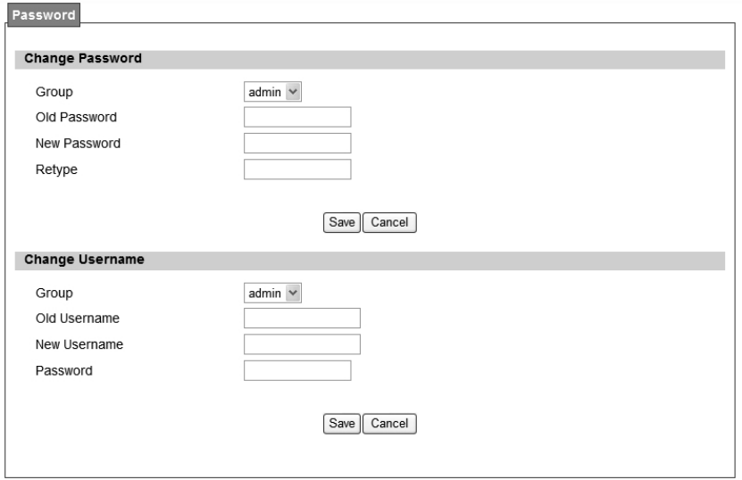
86
5.2. Password
Note: The default usernames and passwords admin/admin and guest/guest.
The user with administrative privileges (belonging to the “ad min” group) has access to all the
features in the software. A user with “guest” privileges (belonging to the “guest” group)only has
a subset of the features available to them.
Note: There can only be one username in each of the groups (one to one relationship).
Figure 55 Administrator>Password

87
Name Description
Change Password
Group
Select which grou p the u ser belongs t o that you would like to
change the password for.
admin, if the user is p art of the admin g roup, they have full
access to tall the features.
guest, if the user is part of the guest group, they have limited
access to the features.
Old Password Enter the old password.
New Password Enter the new password.
Retype Retype the new password.
Save Commit the chang es made and save to WiMAX outdoor CPE, it
will only commit the change made to the password.
Cancel Reset fields to the last saved values.
Change Username
Group
Select which grou p the u ser belongs t o that you would like to
change the username for.
admin, if the user is p art of the admin g roup, they have full
access to tall the features.
guest, if the user is part of the guest group, they have limited
access to the features.
Old Username Enter the username you want to change.
New Username Enter the new username.
Password
Enter the original password, the pa ssword will not change. If you
enter an incorrect or different password the change will not be
committed
Save
Commit the chang es made and save to WiMAX outdoor CPE, it
will only commit the change
made to the username.
Cancel Reset fields to the last saved values.
Table 32 Field definition for Administrator>Password
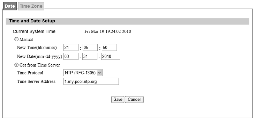
88
6. System
6.1. Date and Time
User can co nfigure the d ate and time on the device. The use r can ma nually configu re the
system time, or ch oose to get the date and time from a time server . The “Sa ve” button will
commit the configuration, and the “Cancel” button will clear the fields. The “Time Zone” tab will
allow you to set the time zone and set the st arting and finish time for d aylight saving period.
User can also enable or disable “Daylight Savings Time”.
NOTE: If user doe sn’t configure the time on the WiMAX out door CPE it will use the defaul t
system starting time. The default system starting time is set to 1970/1/1 00:00:00
Figure 56 System>Date/Time>Date
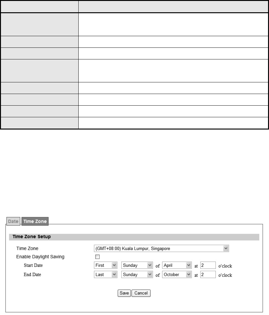
89
6.1.1. Date
Name Description
Manual If user selects the Manual option, then use need to enter the time
and date manually.
New Time New time manually entered
New Date New date manually entered
Get From Time Server If user select s this option it will get th e local time from a time
server automatically.
Time Protocol Select the Time protocol
Time Server Address Enter the address of the time server.
Save Commit the changes made and save to WiMAX outdoor CPE
Cancel Reset fields to the last saved values
Table 33 Field definition for Administrator>Password
6.1.2. Time Zone
Figure 57 System>Date/Time>Time Zone

90
Name Description
Time Zone Enter the time zone of for the location
Enable Daylight Savings If user wants to ena ble Daylight Savi ngs Ti me, u ser needs to
check the box.
Start Date Enter the beginning date for Daylight Savings time
End Date Enter the end date for Daylight Savings time.
Save Commit the changes made and save to WiMAX outdoor CPE
Cancel Reset fields to the last saved values
Table 34 Field definition for System>Date/Time>Time Zone
6.2. Upgrade Firmware
The “Upgrade” window allows user to upgrade the firmware on your device. Users can choose
to upgrade the firmware by entering the file path or entering the URL of the upgrade file.
Note: After pressing the “Upgrade” button. It will automatically reboot the WiMAX outdoor CPE
and upgrade the firmware with the spe cified file. User will be prompted to login to the WiMAX
outdoor CPE after the upgrade is complete.
6.2.1. Upgrade File
Figure 58 System>Upgrade Firmware>Upgrade File
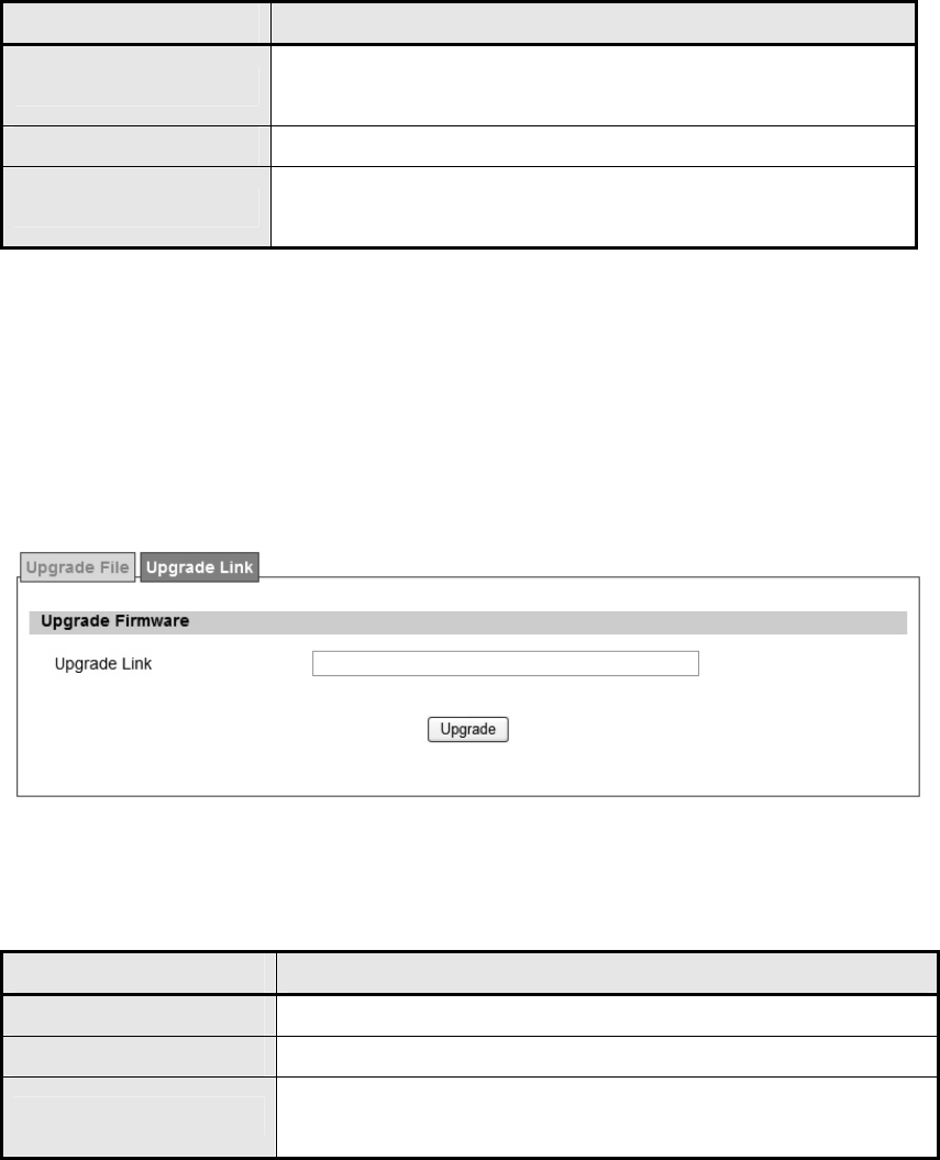
91
Name Description
Browse Enter the full path of the file you want to upgrad e. The "browse"
button will help user to find the file on the server.
Upgrade It will start upgrading the file
Status The status bar will display whic h segment it's processi ng and
what percentage of the upgrade has been completed.
Table 35 Field definition for System>Upgrade Firmware>Upgrade File
6.2.2. Upgrade Link
Figure 59 System>Upgrade Firmware>Upgrade Link
Name Description
Upgrade Link Enter the complete URL path of the file that user wants to upgrade
Upgrade It will start upgrading the file
Status The status window will display which segment it's processing and
what percentage of the upgrade has been completed.
Table 36 Field definition for System>Upgrade Firmware>Upgrade Link
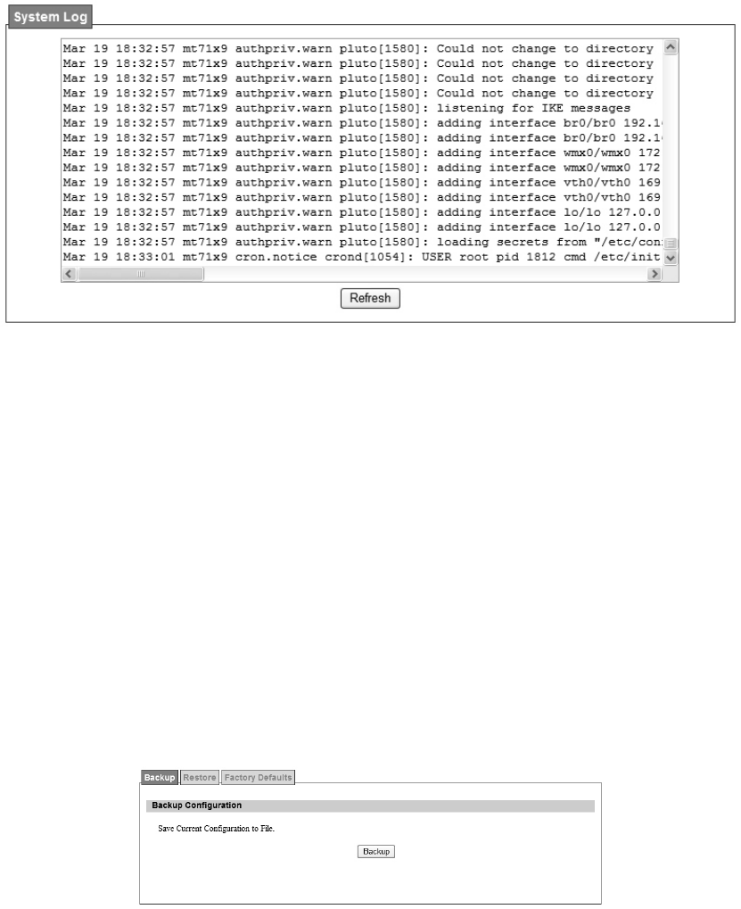
92
6.3. Log
The “Sy stem>Log” will di splay system log out put. The “Ref resh” button will clear the l og
window and display the most current system log information.
Figure 60 System Log
6.4. Backup/Restore
The Backup/Restore tab will allow user to save and restore the configuration on the WiMAX
outdoor CPE . User can a lso re set the WiM AX out door CPE to factory defa ults from the
“Factory Defaults” tab.
6.4.1. Configuration Backup
Figure 61 System>Backup/Restore>Backup
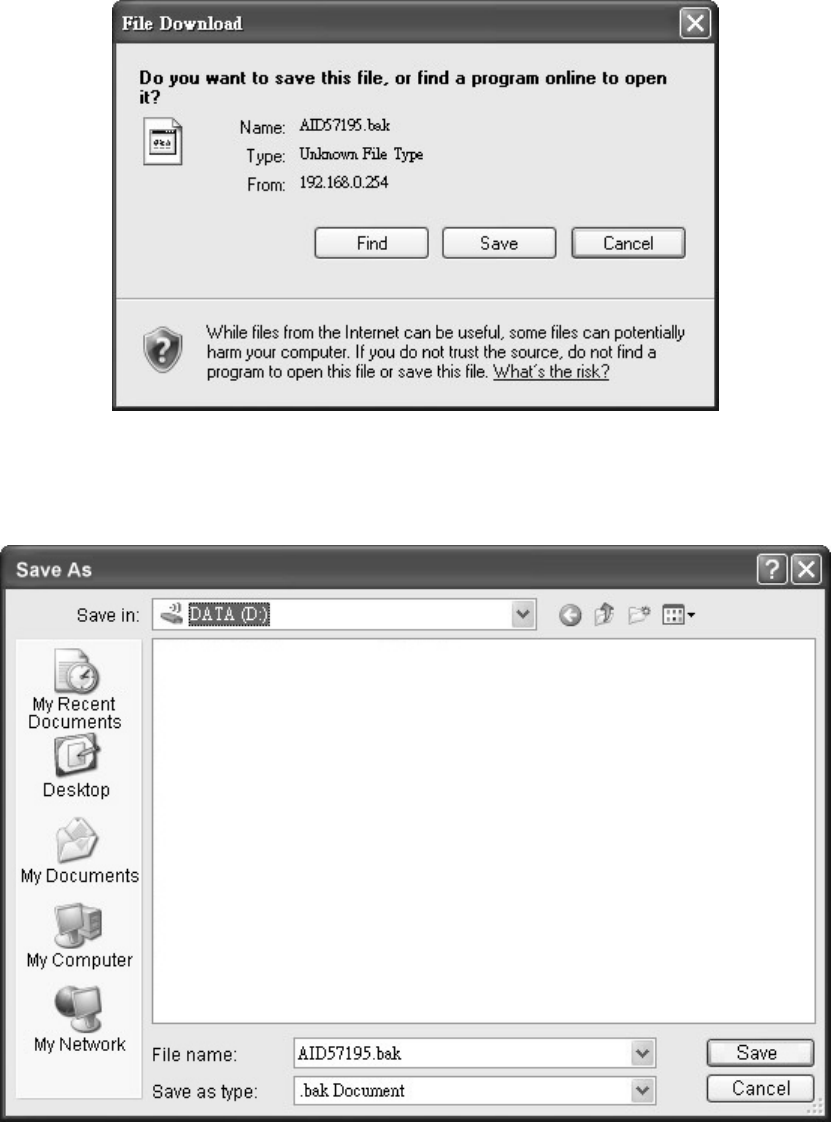
93
Figure 62 File Download
Figure 63 Save File As
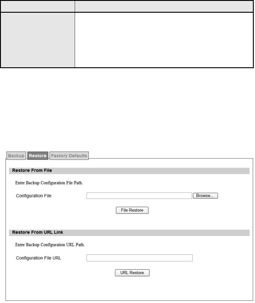
94
Name Description
Backup
Click the "Backup" button o save the current configuration on the
WiMAX outdoor CPE. After user clicks the "Backup" button "File
Download" window will pop-up and prompt user to save the file.
In the "Save As" windo w, enter the na me and location, where
user wishs to download the file to.
Table 37 Field definition for System>Backup/Restore>Backup
6.4.2. Configuration Restore
Figure 64 System>Backup/Restore>Restore

95
Name Description
File Restore
Enter the path of the configuration file user wants to restore. Click
on the "Bro wse" button to help u ser to navig ate throu gh
directories and search for the file. After user enters the complete
file path, click the "File Re store" button. It will begin restoring the
configuration from the file specified.
URL Restore
Enter the configuration URL path user wants to restore from. After
entering the complete URL path, click the "URL Restore" button. It
will begin restoring the configuration from the URL l ocation user
specified.
Table 38 System>Backup/Restore>Restore
6.4.3. Factory Defaults
Factory default will set all the configurations back to factory def aults. Any configurations that
user ha s ma de will be ch anged back to the factory default settings. Af ter sel ecting “Re set”
button, user will be prompted with a window to confirm or cancel the action.
Warning: Restore factory defaults will clear any IP addresses and setting that may have been
configured on the WiMAX outdoor CPE.
Figure 65 System>Backup/Restore>Factory Defaults
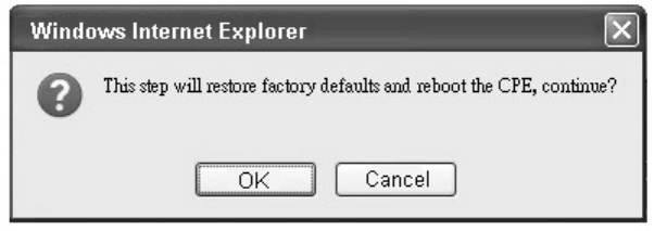
96
Figure 66 Restore to factory reset warning

97
7. Installing and grounding device
Before installing the Outdoor CPE Device
Before installing, it is important to comply with the precautions listed below.
It must be install ed by qua lified ser vice personn el who ar e w ell-trained in the correct proce dures for handling an d installing the
equipment.
Avoid in stalling or working o n equipment in ad verse weather conditions. On ce it must be i nstalled in adverse weather co nditions, i t’s
necessary to well protect the equipment.
Do not install the device near overhead power lines or power circuits, or where the device can fall onto such power lines or circuits.
Do not disassemble the product. Opening or removing covers may expose you to electric shock. Warranty void if seal is broken.
Do not place or construct objects in close proximity to the device.
Be sure to check the supplied mounting accessory is correct as listed in Figure 67. Please be noted that the mounting kits should be used
for the pole with diameter between 34 ~ 49 mm.
Under normal operating condition, it should be at least 50 cm away from the body of the user.
Mounting Accessories:
Bracket with Tab: 1 pc
Bracket W/L Tab: 1 pc
Arm Bracket: 1 pc
Screws with length 60mm: 2 pcs
Screws with length 35mm: 2 pcs
Nuts: 3 pcs
Split Washers: 3 pcs
Flat Washers: 3 pcs
Lockwasher: 2 pcs
Figure 67 Mounting accessory list
An Overview of the Outdoor CPE Device Installation
Service personnel needs to follow the steps for installing Outdoor CPE Device
1. Pole-mounting or Wall-mounting the Outdoor CPE Device.
2. Grounding the Outdoor CPE Device
3. Connect the Outdoor CPE Device to PoE unit
4. Connect PC to PoE unit for configuring the Outdoor CPE Device
5. Connect the PoE unit to the power source to power up the Outdoor CPE Device
6. Use PC to configure the Outdoor CPE Device
Pole-Mounting the Outdoor CPE Device
In the following steps, it introduces how to pole-mounting the Outdoor CPE Device.
1. Assemble the mounting hardware brackets onto pole first: Take the Screws with 60mm length to pass through the Split washer and Flat
washer in order, and then screw the Brackets together with nuts.
2. Use the Screw with 35mm length to attach the Outdoor CPE Device to the tab of the Bracket. Ensure the Lockwasher is located between
the Bracket’s tab and the Outdoor CPE Device’s tab. Be sure to orient the Outdoor CPE Device with the connector towards the bottom.
Remember to orderly add the Split washer, Flat washer and Nuts as shown in Figure 68. Do not over-tighten before finishing the Outdoor
CPE Device alignment.
3. Adjust the azimuth and elevation of the Outdoor CPE Device toward the direction of WiMAX Base Station location.
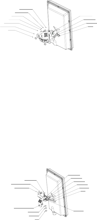
98
4. Tighten the screws to secure the Outdoor CPE Device tightly.
It is not necessary to use Arm Bracket for pole-mounting. Arm Bracket is only used for wall-mounting.
Nut
Bracket W/L Tab
Bracket with Tab
Flat washer
Split washer
Screw (60mm)
Screw (35mm)
Nut
Flat washer
Split washer
Lockwasher
Figure 68 Pole-Mount the Outdoor CPE Device
Wall-Mounting the Outdoor CPE Device
In the following steps, it introduces how to wall-mounting the Outdoor CPE Device.
1. Install the Bra cket with tab on a wall b y usi ng t wo mou nting scre ws appr opriate for the wall’s con struction m aterial. T he ap propriate
mounting hardware should be purchased directly from a local supplier.
2. Connect the Arm Bracket to Outdoor CPE Device with the 35mm length Screw, Lockwasher, Split washer, Flat washer, and Nut orderly as
shown in Figure 69. Ensure the Lockwasher is located between the Bracket’s tab and the Outdoor CPE Device’s tab. Do not over-tighten
before finishing the Outdoor CPE Device alignment.
3. Secure the other side of Arm Bracket along with Lockwasher to the Bracket’s tab mounted on wall. Ensure that the bolt head is positioned in
the socket of the Bracket. Do not over-tighten before finishing the Outdoor CPE Device alignment.
4. Adjust the azimuth and elevation of the Outdoor CPE Device toward the direction of WiMAX Base Station location.
5. Tighten the screws to secure the Outdoor CPE Device tightly.
Nut
Flat washer
Split washer
Lockwasher
Arm Bracket
Customer supplied screw
Nut
Flat washer
Split washer
Screw (35mm)
Bracket with Tab
Screw (35mm)
Customer supplied screw
Lockwasher
Figure 69 Wall-Mount the Outdoor CPE Device
Grounding the Outdoor CPE Device
Grounding the Out door C PE Device is e ssential to a void serious i njury to ser vice pers onnel an d damage t o t he Outdoor CPE Device. T he
following steps introduce how to ground the Outdoor CPE Device.
1. Remove the ground screw installed on the side of the Outdoor CPE Device, as shown in Figure 70.
2. Cut the required length of the ground wire, and then strip the insulation from the ground wire by using either a wire cutter/stripper or utility
knife.
3. Crimp the ground wire to the copper cable lug, and then connect the cable lug to the grounding connection on the side of the Outdoor CPE
Device. Please be noted that the thickness of the cable lug should be less than 0.85mm.
4. Tighten the screw by using the appropriate size and type of screw driver to secure the copper cable lug to the Outdoor CPE Device.
5. Strip the other end of the ground wire and connect to the main ground.
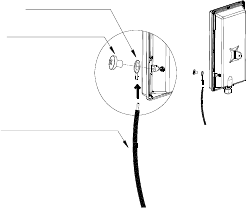
99
Copper Cable Lug
Ground Wire to Earth
Grounding Screw
Figure 70 Connect the ground wire

100
Specification
Physical Standard Description XS-618-25MM
PoE Standard- IEEE802.3af Compliant ●
Wireless Standard - IEEE802.16e-2005 ●
General Standard
Ethernet Interface - 10 /100 Base-T ●
WiMAX Specification
Radio Frequency 2500MHz~2690MHz ●
Air Interface Scalable OFDMA ●
RF Configuration TX& RX Configuration 2T2R
Modulation - DL & UL QPSK, 16QAM, 64QAM ●
Channel Bandwidth 5, 10 MHZ ●
CTC-QPSK-1/2 @ 5MHz BW
CTC-16QAM-3/4@ 5MHz BW
CTC-64QAM-3/4@ 5MHz BW
- 95 dBm
- 85 dBm
- 80 dBm
Receiver Sensitivity
CTC-QPSK-1/2@10MHz BW
CTC-16QAM-3/4@10MHz BW
CTC-64QAM-3/4@10MHz BW
- 92 dBm
- 83 dBm
- 78 dBm
Firmware Feature
Bridge /Gateway Switching Mode ●
DDNS /DNS Relay ●
Network Time Protocol ●
IPv4 ●
Network Address Translation ●
DHCP Client-WAN /DHCP Server-LAN ●
Port Forwarding /Trigger Support ●
NAT ALG -NAT FTP /PPTP /H.323 ALG ●
Networking
UPnP, NAT-PMP & IGMP Proxy Support ●
TR-069 /OMADM /SNMPv2 MIB II ●
HTTP /HTTPS /SSH /Telnet ●
BS Scanning- Auto /Manual Connection ●
Web Access User Interface ●
Web Link Status Display ●
Web System Log Display ●
User Account Permission Control ●
Web Firmware Upgrade /Firmware Rollback ●
Network Management
Rest Factory Default Configuration
&Settings ●
QoS Scheduling UGS; RT-VR; NRT-VR; BE; ERT-VR ●
VLAN VLAN packet pass through ●

101
VPN PPTP Server /Client, L2TP Server /Client
VPN Pass Through-IPSec, PPTP, and L2TP ●
Authentication User /Device /User and Device
Authentication ●
Security AES-CCM /CBC /ECB /Key Wrap
PKM v2, EAP TLS /TTLS /
MSCHAPv2 /MS-CHAP /CHAP /MD5 /PAP
X.509 Certificate
●
Firewall IP Filter, DDOS, DMZ, NAT /NAPT Support ●
Mechanical Specification
Dimension (L xW xH) 354 x 220 x 68 mm (Without Tab)
354 x 220 x 102 mm (With Tab)
CPE Weight /without Accessories < 2 Kg
Power Requirements 100 ~ 240VAC /50 ~ 60Hz
Power Input Voltage + 48VDC
Power Consumption@Continue TX Mode <=15 W
Output Power @Antenna Port >= 25 dBm
Antenna /Internal Patch Antenna >= 14 dBi
LAN Port /RJ45 Connector 1xRJ45 Port
Operating Temperature@Ambient Temp. -40℃ ~ + 60℃
Operation Humidity /Non-condensing 5 to 85%
Storage Temperature@Ambient Temp. - 40℃ ~ + 85℃
Storage Humidity /Non-condensing 5 to 85%
Grounding Design ●
Surge Protection +/- 4 KV
Hardware Specification
Waterproof & Anti-Dust IP67 Compliance