Greenheck Fan Canopy Type Kitchen Hoods 452413 Users Manual
452413 to the manual ed8570c3-b7e3-47f7-87f5-71879022c07d
2015-02-09
: Greenheck-Fan Greenheck-Fan-Canopy-Type-Kitchen-Hoods-452413-Users-Manual-562519 greenheck-fan-canopy-type-kitchen-hoods-452413-users-manual-562519 greenheck-fan pdf
Open the PDF directly: View PDF ![]() .
.
Page Count: 40
Please record the Serial, Model #, and Mark for the hood and other equipment for future reference.
Serial #: _______________________ Model #: ______________________ Mark: _________________
Serial #: _______________________ Model #: ______________________ Mark: _________________
Serial #: _______________________ Model #: ______________________ Mark: _________________
Serial #: _______________________ Model #: ______________________ Mark: _________________
Serial #: _______________________ Model #: ______________________ Mark: _________________
Serial #: _______________________ Model #: ______________________ Mark: _________________
Serial #: _______________________ Model #: ______________________ Mark: _________________
Serial #: _______________________ Model #: ______________________ Mark: _________________
Serial #: _______________________ Model #: ______________________ Mark: _________________
Serial #: _______________________ Model #: ______________________ Mark: _________________
Serial #: _______________________ Model #: ______________________ Mark: _________________
Installation, Operation and Maintenance Manual
Please read and save these instructions. Read carefully before attempting to assemble, install, operate or maintain the
product described. Protect yourself and others by observing all safety information. Failure to comply with instructions
could result in personal injury and/or property damage! Retain instructions for future reference.
®
PN 452413
Canopy Type Kitchen Hoods
1Canopy Hood

2Canopy Hood
®
Receiving and Handling .............................................................4
Storage ..........................................................................4
Hood Weights .....................................................................4
Installation ........................................................................5
Hood Installation Overview...........................................................5
Filler Panels .......................................................................5
Hood Hanging Height ...............................................................6
Continuous Capture Plenum..........................................................6
Double Island Style Hood ............................................................6
U-Channel Strips ...................................................................6
Electrical Connections ..............................................................7
Ductwork .........................................................................7
Installation Instructions for the External Supply Plenums................................ 8 - 9
Installation Instructions for the Back Supply Plenum (BSP) ................................10
Installing the Supply Duct Collar .....................................................10
Hanging the Back Supply Unit .......................................................10
Hanging the Hood .................................................................11
Air Diffusers ......................................................................11
Enclosure Panel Installation Instructions ...............................................12
End Skirt Installation Instructions.....................................................13
Backsplash Panel Installation Instructions ......................................... 14 - 15
Duct Collar Installation Instructions for GH, GK and GX Series Hoods .......................16
Exhaust Air Balancing Baffle ........................................................17
Balancing the Kitchen Exhaust.......................................................18
Baffle Filters (GH Series) .................................................. 18 - 21
High Velocity Cartridge Filters (GK Series).................................... 22 - 23
High Efficiency Filters (GX Series) .......................................... 24 - 25
Short Circuit Hoods ..........................................................26
Fire Suppression Wiring Diagrams ................................................ 27 - 28
Overall Wiring Plan View ............................................................29
Wiring for Hood Switch Panels.......................................................30
Circuit Diagram ...................................................................31
Table of Contents

3Canopy Hood
®
Maintenance .....................................................................32
Grease Grabber™ Cleaning and Maintenance ...................................... 33 - 34
Filter Cleaning Frequency Chart......................................................35
Troubleshooting Guide ......................................................... 36 - 37
Replacement Parts ............................................................ 38 - 39
Warranty ........................................................................40
Table of Contents
4Canopy Hood
®
Upon receiving the equipment, check for both obvious and hidden damage. If damage is found, record all
necessary information on the bill of lading and file a claim with the final carrier. Check to be sure that all parts of
the shipment, including accessories, are accounted for.
STORAGE
If a kitchen hood must be stored prior to installation it must be protected from dirt and moisture. Indoor storage
is recommended. For outdoor storage, cover the hood with a tarp to keep it clean, dry, and protected from UV
(Ultra Violet) Radiation damage.
Improper storage which results in damage to the unit will void the warranty.
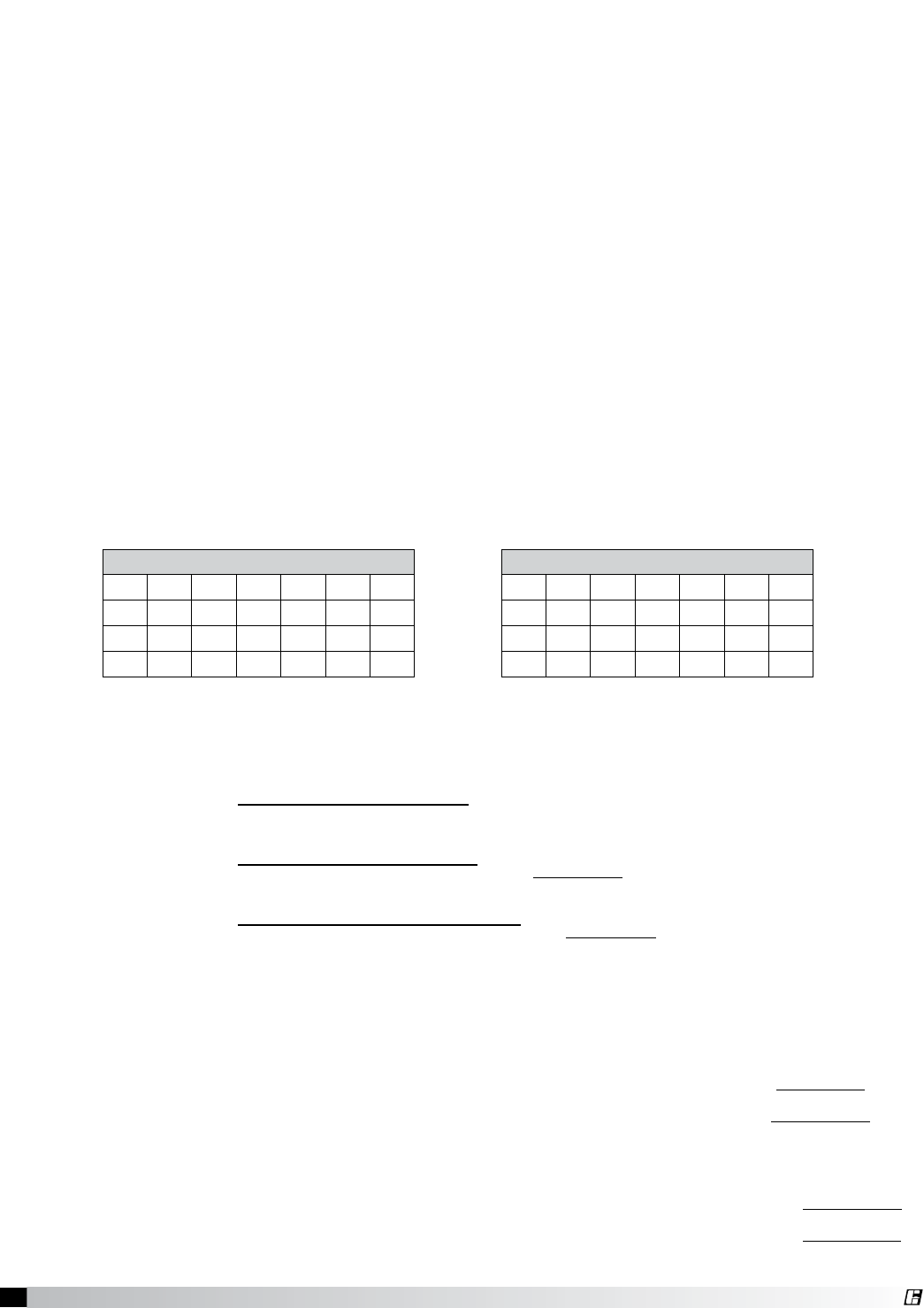
HOOD
MODEL
HOOD DEPTH (MULTIPLY BY LENGTH) FOR HOOD WEIGHT
3 ft.
.914 m
3.5 ft
1.067 m
4 ft
1.2192 m
4.5 ft
1.3716 m
5 ft
1.524 m
5.5 ft
1.6764 m
6 ft
1.8288 m
6.5 ft
1.9812 m
7 ft
2.1336 m
7.5 ft
2.286 m
GH, GK,
GXEW
30 lbs/ ft.
44.64
kg/m
32 lbs/ft
47.62
kg/m
35 lbs/ft
52.08
kg/m
38 lbs/ft
56.54
kg/m
40 lbs/ft
59.52
kg/m
GH, GX,
GXDW
36 lbs/ft
53.57
kg/m
38 lbs/ft
56.44
kg/m
41 lbs/ft
61.01
kg/m
44 lbs/ft
65.47
kg/m
46 lbs/ft
68.45
kg/m
GH, GK,
GXFW
40 lbs/ft
59.52
kg/m
44 lbs/ft
65.47
kg/m
48 lbs/ft
71.42
kg/m
52 lbs/ft
77.38
kg/m
GH, GK,
GXCW
48 lbs/ft
71.42
kg/m
51 lbs/ft
71.89
kg/m
54 lbs/ft
81.35
kg/m
57 lbs/ft
84.82
kg/m
GH, GK,
GXSW
44 lbs/ft
65.47
kg/m
48 lbs/ft
71.42
kg/m
52 lbs/ft
77.38
kg/m
56 lbs/ft
83.33
kg/m
GGEW
39 lbs/ft
58.03
kg/m
41 lbs/ft
61.01
kg/m
44 lbs/ft
65.47
kg/m
47 lbs/ft
69.94
kg/m
49 lbs/ft
72.91
kg/m
GGDW
45 lbs/ft
66.96
kg/m
47 lbs/ft
69.94
kg/m
50 lbs/ft
74.40
kg/m
53 lbs/ft
78.86
kg/m
55 lbs/ft
81.84
kg/m
GGFW
49 lbs/ft
72.91
kg/m
53 lbs/ft
78.86
kg/m
57 lbs/ft
84.82
kg/m
61 lbs/ft
90.77
kg/m
GGCW
57 lbs/ft
84.82
kg/m
60 lb/ft
89.28
kg/m
63 lbs/ft
93.74
kg/m
66 lbs/ft
98.21
kg/m
GGSW
53 lbs/ft
78.86
kg/m
57 lbs/ft
84.82
kg/m
61 lbs/ft
90.77
kg/m
65 lbs/ft
96.72
kg/m
GH, GK,
GXEV
52 lbs/ft
77.38
kg/m
54 lbs/ft
81.35
kg/m
56 lbs/ft
83.33
kg/m
58 lbs/ft
86.30
kg/m
61 lbs/ft
90.77
kg/m
63 lbs/ft
93.74
kg/m
GH, GK,
GXFV
61 lbs/ft
90.77
kg/m
66 lbs/ft
98.21
kg/m
68 lbs/ft
101.18
kg/m
72 lbs/ft
107.14
kg/m
75 lbs/ft
111.6
kg/m
79 lbs/ft
117.55
kg/m
GH, GK,
GXCV
81 lbs/ft
120.53
kg/m
84 lbs/ft
124.99
kg/m
87 lbs/ft
129.46
kg/m
90 lbs/ft
133.92
kg/m
GH, GK,
GXSV
66 lbs/ft
98.21
kg/m
69 lbs/ft
102.67
kg/m
72 lbs/ft
107.14
kg/m
76 lbs/ft
113.09
kg/m
79 lbs/ft
117.55
kg/m
Receiving and Handling
5Canopy Hood
®
NOTE: If you have a Back
Supply Plenum (BSP), this must
be installed before the hood.
Please see Page 10.
For Wall/Single Island Style
Hoods, prior to installation,
check with local authorities
having jurisdiction on clearances
to combustible surfaces, etc.
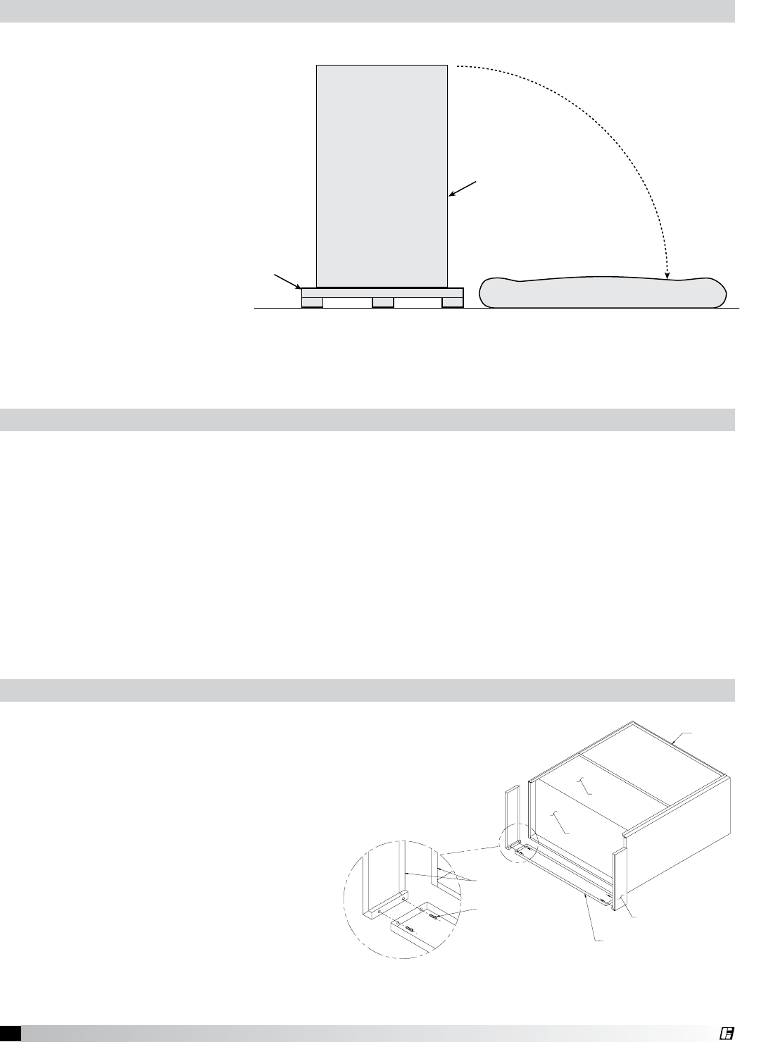
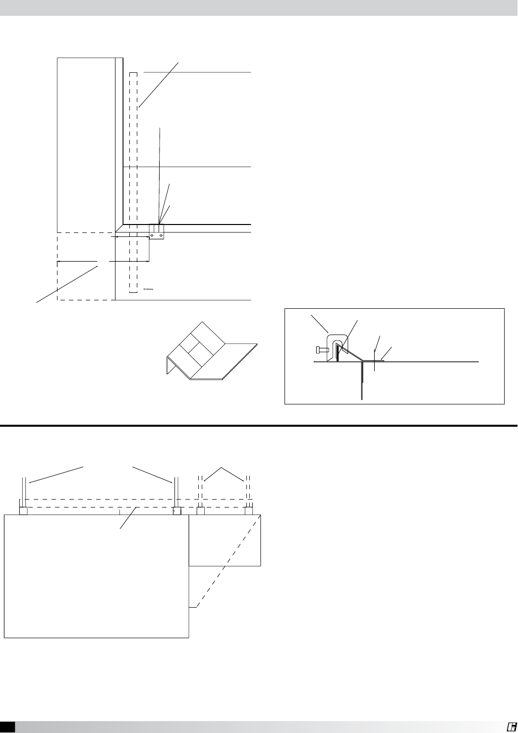
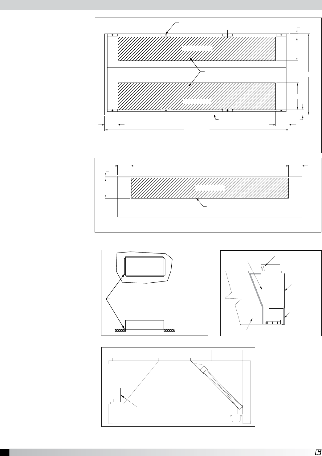
With the hood still inside its
packing crate, position the unit
beneath its installation location.
Carefully remove the packing
crate. Place some protective
material on the floor next to
the crate to avoid damaging the hood as it is tipped on its side; Fig. 1. Tip the hood carefully onto the
protective material. If you have filler panels, install them now; Fig. 2. If you have integral filler panels,
no additional installation is needed.
Front
1/2 in. threaded rod by
Bottom
Pallet
Protective Material
Fig. 1
If a Back Supply Plenum is provided, install first. Before raising hood, insert 1/2 in. (12.7 mm) diameter
threaded rod (by others) into hanger brackets on hood top. Check the engineering drawings or UL
label located on the inside of the hood for proper hood height above finished floor. Install filler panels
if needed. Raise and hang hood from adequate roof or ceiling supports All hanger brackets must be
used and the hood must be properly supported while lifting to prevent damage or distortion to the
hood. The hood must be hung level to operate properly. After hood is secured, make the exhaust duct
connections. The fire system distributor must be contacted at this time. After the fire system has been
installed, mount the enclosures, then the supply plenums. If an Horizontal Supply Plenum is provided,
it should be installed before the enclosures. The hood and accessories are now installed. Finally, make
the electrical connections from switches to fans and complete the fire system circuits as required by
the job specification.
Hood Installation Overview
HOOD
HOOD
HOOD
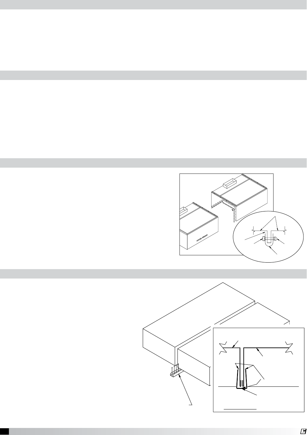
RIGHT FILLER P A NEL
BOTTOM FILLER P A NEL
T A CK-WELDED TO
HOOD BACK
5/16 IN. X 3/4 IN. BOL T S
WITH WA SHERS & NUTS
1. Uncrate the hood and lay it on the floor
with protective material between the hood
and the floor. (Fig. 1)
2. Bolt the filler panels together with 5/16 in.
bolts provided in the hardware package.
3. Position the filler panels to the hood back,
and tack-weld them into place. (Fig. 2)
4. To allow for ease of cleaning, caulk
the external seams with NSF Approved
silicone caulk (GE SCS1009, or its
equivalent). The caulk is not provided.
Fig. 2
Filler Panel Installation Instructions
Installation
6Canopy Hood
®
Before hanging the hoods, please verify the hood marks to make sure the correct hood is
hung on the correct side.
A double island hood is created by installing two wall style hoods back to back. Use the installation
procedure described on page 5 for single island hoods; install and level both hoods. After leveling,
secure the hoods together by tack-welding and/or bolting the rear mounting brackets. Caulk this joint
with NSF Approved silicone caulk (GE SCS1009 or its equivalent). The caulk is not provided.
HOOD FRONT
ITEM-1B
DOUBLE ISLAND CLIP
HOOD-1B
DETAIL A
DOUBLE ISLAND CLIP
SILICONE CAULK
(GE SCS1009)
HOOD-1A
INSTALLATION INSTRUCTIONS
1. AFTER HOOD IS HUNG IN POSITION AND LEVELED.
2. APPLY SILICONE CAULK TO INSIDE OF DOUBLE
ISLAND CLIP.
3. POSITION AND INSTALL CLIP BY TAPPING
INTO POSITION ALONG CLIP (FRICTION FIT).
4. CAULK EDGES TO SEAL OUT
GREASE AND ALLOW FOR EASE
OF CLEANING.
ITEM-1A
Double Island Style Hoods
Remove the support angles on the open end panels. (see
Fig. 3) Use the installation procedure described on page
4 for single island hoods; install and level both hoods.
After leveling, secure the hoods together by tack-welding
and/or bolting the top angles. Fasten the hoods together
using u-clips and bolts, (see Fig. 4). Caulk this joint
with NSF Approved silicone caulk (GE SCS1009 or its
equivalent). The caulk is not provided.
2. RAI
S
E ALL H
OO
D
S
INT
O
APPR
O
PRIATE L
OC
ATI
O
N
AND
SU
PP
O
RT PER
CO
N
S
TR
UC
TI
O
N PLAN
S.
3. FASTEN TOP ANGLES TOGETHER USING 1/4 in. BOLTS & NUTS
(
BY OTHERS
).
4. FASTEN HOODS TOGETHER USING U-CLIPS
,
1/4 in. BOLT
S
5.
C
A
U
LK ALL
S
EAM
S
A
S
NE
C
E
SS
ARY
.
&
C
AP N
U
T
S
A
S
INDI
C
ATED
.
HOOD FRONT
1. REM
O
VE
SU
PP
O
RT AN
G
LE
O
N
O
PEN END PANEL
.
H
OOD
ACO
RN N
UT
B
O
L
T
U
-
C
LI
P
C
A
U
L
K
Fig. 3
Fig. 4
Continuous Capture Plenum Hoods
Installing U-Channel Strip
The hood hanging height is critical, hanging the hood at the incorrect height may significantly reduce
the ability for the hood to function properly and may be in violation of codes. The hood hanging height
(typically, 78 in. (198.12 cm) above the finished floor) is given on the UL label located on the inside of
the hood on the end panel. The hood must be hung level to operate properly. The grease trough is
pitched to drain into the grease container.
Hood Hanging Height
Fig. 5
1. After the hood is hung in position and
leveled, apply caulk to the inside edge
of the double island clip. (Fig. 5)
2. Position and install the clip by tapping
into position along clip (friction fit).
3. Caulk edges to seal out grease and
allow for ease of cleaning. Caulk with
NSF Approved silicone caulk
(GE SCS1009 or its equivalent). The
caulk is not provided.
HOOD FRONT
ITEM-1B
DOUBLE ISLAND CLIP
HOOD-1B
DETAIL A
DOUBLE ISLAND CLIP
SILICONE CAULK
(GE SCS1009)
HOOD-1A
INSTALLATION INSTRUCTIONS
1. AFTER HOOD IS HUNG IN POSITION AND LEVELED.
2. APPLY SILICONE CAULK TO INSIDE OF DOUBLE
ISLAND CLIP.
3. POSITION AND INSTALL CLIP BY TAPPING
INTO POSITION ALONG CLIP (FRICTION FIT).
4. CAULK EDGES TO SEAL OUT
GREASE AND ALLOW FOR EASE
OF CLEANING.
ITEM-1A

7Canopy Hood
®
Note: The installation of the canopy hoods shall be in accordance with NFPA 96 (latest edition),
Standard for Ventilation Control & Fire Protection of Commercial Cooking Operations.
After the hood is installed, remove all protective plastic.
Note: Greenheck does not recommend walking or standing on the hood top as damage can result. If
you must walk on the hood top, protect the hood with additional support or planks for flooring.
Ductwork
Electrical Connections
Access for wiring the hood control panel (when applicable) is provided by a junction box located on
top of the hood when the control panel is mounted in the hood, or by the switch junction box when the
control panel is mounted in the fire protection cabinet. The box is labeled “Control Voltage Wiring to
Roof Top Fan Package”. Use minimum 14 AWG copper wire. After all the wiring is completed, install
the light bulbs (light bulbs not provided; standard light bulbs up to 100 watt may be used).
Caution: For multiple hood systems that have more than 14 lights total (incandescent or fluorescent),
the hood lights must be wired to multiple circuits. Each circuit must have less than 14 lights total.
Standard Greenheck light switches shipped on hoods are rated for 15 amps and shall not have more
than 14 lights connected to them. Higher amperage switches are available upon special request.
Exhaust
As specified in NFPA 96, Ch. 7.5 (latest edition), exhaust duct systems must be constructed in the
following manner:
Materials. Ducts shall be constructed of and supported by carbon steel not less than 1.37 mm
(0.054 in.) (No. 16 MSG) in thickness or stainless steel not less than 1.09 mm (0.043 in.) (No. 18 MSG)
in thickness.
Installation: All seams, joints, penetrations, and duct to hood collar connections shall have a
liquid-tight external weld. If you have an Automatic Fire Damper please refer to that manual for
installation instructions now.
Supply
Supply ductwork (where applicable) should be connected to the hood in a manner approved by the
local code authorities.
Note: For hoods with fire dampers in the exhaust and supply duct collars, an access panel for cleaning
and inspection shall be provided in the duct. This panel shall be as close to the hood as possible but
should not exceed 18 in. (45.72 cm).
For proper installation of duct collars when they are shipped unattached, see page 16.
8Canopy Hood
®
HOOD STANDING SEAM
HANGING CLIP BOLTED TO PLENUM SHELL
HANGING CLIP
HOOD FRONT
"C" CLAMP
SUPPLY PLENUM SHELL
HANGER BRACKET
END VIEW
THREADED ROD
HOOD
ATTACH HANGING CLIP TO
HOOD STANDING SEAM WITH
THE SUPPLIED "C" CLAMPS
(OPTIONAL: DRILL AND BOLT A
1/4-20 SS BOLT THROUGH
THE CLIP AND HOOD STANDING
SEAM)
HANGING METHODS FOR SUPPLY PLENUMS
ASP, FSP AND VSP
TOP VIEW
HOOD
TOP VIEW
SUPPLY PLENUM
2 CLIPS ARE NEEDED
3 CLIPS ARE NEEDED
FOR PLENUMS > 96"
FOR PLENUMS <= 96"
THE THIRD CLIP IS LOCATED
IN THE CENTER OF THE PLENUM
LENGTH
THREADED ROD
OPTION #3
HANGING CLIP
OPTION #1
OPTION #1
ON THE END OF THE HOOD
HANGING CLIP COULD BE 23.5" FROM
END IF THERE IS A UTILITY CABINET
OPTION #1
OPTION #1
THE HOOD AND IS MOUNTED TO THE ASP
HOOD UP CANTILEVERS OVER THE END OF
THE UNI-STRUT (U-CHANNEL) THAT HOLDS THE
HANGER BRACKETS
OPTION #2
OPTION #2
UNI-STRUT SUPPLIED BY OTHERS
OPTION #1 = HANGING CLIP
OPTION #2 = UNI-STRUT
OPTION #3 = THREADED ROD
OPTIONAL UTILITY CABINET
NOTE: SUPPLY PLENUMS ARE STANDARDLY SUPPLIED WITH HANGING CLIPS (OPTION 1),
IF OPTION #1 IS NOT APPLICABLE
,
USE OPTIONS 2 0R 3
SUPPLIED BY OTHERS
11.5
23.5
HOOD STANDING SEAM
HANGING CLIP BOLTED TO PLENUM SHELL
HANGING CLIP
HOOD FRONT
"C" CLAMP
SUPPLY PLENUM SHELL
HANGER BRACKET
END VIEW
THREADED ROD
HOOD
ATTACH HANGING CLIP TO
HOOD STANDING SEAM WITH
THE SUPPLIED "C" CLAMPS
(OPTIONAL: DRILL AND BOLT A
1/4-20 SS BOLT THROUGH
THE CLIP AND HOOD STANDING
SEAM)
HANGING METHODS FOR SUPPLY PLENUMS
ASP, FSP AND VSP
TOP VIEW
HOOD
TOP VIEW
SUPPLY PLENUM
2 CLIPS ARE NEEDED
3 CLIPS ARE NEEDED
FOR PLENUMS > 96"
FOR PLENUMS <= 96"
THE THIRD CLIP IS LOCATED
IN THE CENTER OF THE PLENUM
LENGTH
THREADED ROD
OPTION #3
HANGING CLIP
OPTION #1
OPTION #1
ON THE END OF THE HOOD
HANGING CLIP COULD BE 23.5" FROM
END IF THERE IS A UTILITY CABINET
OPTION #1
OPTION #1
THE HOOD AND IS MOUNTED TO THE ASP
HOOD UP CANTILEVERS OVER THE END OF
THE UNI-STRUT (U-CHANNEL) THAT HOLDS THE
HANGER BRACKETS
OPTION #2
OPTION #2
UNI-STRUT SUPPLIED BY OTHERS
OPTION #1 = HANGING CLIP
OPTION #2 = UNI-STRUT
OPTION #3 = THREADED ROD
OPTIONAL UTILITY CABINET
NOTE: SUPPLY PLENUMS ARE STANDARDLY SUPPLIED WITH HANGING CLIPS (OPTION 1),
IF OPTION #1 IS NOT APPLICABLE, USE OPTIONS 2 0R 3
SUPPLIED BY OTHERS
11.5
23.5
SUPPLY PLENUM SHELL
HOOD FRONT
HANGING CLIP
2.120
1.000 147.0°
57.4°
1.000
1.000
Form Down 147°
Form Up 57°
1.375
2.1251.000
3.000
0.563
0.563
0.750
0.750
4.500
.500 x .375
SLOT (3 PLACES)
0.625
1.500
0.625
Supply Plenum Clip
Using the Uni-strut
1. The uni-strut (supplied by others) that holds
the hood up cantilevers over the end of the
hood and is mounted to the supply plenum
hanger brackets.
HOOD STANDING SEAM
HANGING CLIP BOLTED TO PLENUM SHELL
HANGING CLIP
HOOD FRONT
"C" CLAMP
SUPPLY PLENUM SHELL
HANGER BRACKET
END VIEW
THREADED ROD
HOOD
ATTACH HANGING CLIP TO
HOOD STANDING SEAM WITH
THE SUPPLIED "C" CLAMPS
(OPTIONAL: DRILL AND BOLT A
1/4-20 SS BOLT THROUGH
THE CLIP AND HOOD STANDING
SEAM)
HANGING METHODS FOR SUPPLY PLENUMS
ASP, FSP AND VSP
TOP VIEW
HOOD
TOP VIEW
SUPPLY PLENUM
2 CLIPS ARE NEEDED
3 CLIPS ARE NEEDED
FOR PLENUMS > 96"
FOR PLENUMS <= 96"
THE THIRD CLIP IS LOCATED
IN THE CENTER OF THE PLENUM
LENGTH
THREADED ROD
OPTION #3
HANGING CLIP
OPTION #1
OPTION #1
ON THE END OF THE HOOD
HANGING CLIP COULD BE 23.5" FROM
END IF THERE IS A UTILITY CABINET
OPTION #1
OPTION #1
THE HOOD AND IS MOUNTED TO THE ASP
HOOD UP CANTILEVERS OVER THE END OF
THE UNI-STRUT (U-CHANNEL) THAT HOLDS THE
HANGER BRACKETS
OPTION #2
OPTION #2
UNI-STRUT SUPPLIED BY OTHERS
OPTION #1 = HANGING CLIP
OPTION #2 = UNI-STRUT
OPTION #3 = THREADED ROD
OPTIONAL UTILITY CABINET
NOTE: SUPPLY PLENUMS ARE STANDARDLY SUPPLIED WITH HANGING CLIPS (OPTION 1),
IF OPTION #1 IS NOT APPLICABLE, USE OPTIONS 2 0R 3
SUPPLIED BY OTHERS
11.5
23.5
Installing External Supply Plenums
Fig. 6
Fig. 7
Fig. 8
Using the Supply Plenum Clip
Note: The supply plenum is provided with
plenum clips that assist in hanging the plenum.
The plenum should not be hung only with the
plenum clips, threaded rod or uni-strut must
also be used.
1. Bolt the hanging clip to the supply plenum.
Two clips are needed for plenums less than
96 in. (243.84 cm) long and three for plenums
greater than 96 in. (243.84 cm). The third clip
is located in the center of the plenum length.
If there is a utility cabinet, the hanging clip
should be 23.5 in. (59.69 cm) from the end to
the hood.
2. Using the c-clamps provided, clamp the
supply plenum hanging clip to the hood
standing seam. Option: Drill and bolt a
1/4-20 SS bolt through the clip and hood
standing seam.
9Canopy Hood
®
ATTACHED AIR CURTAIN CANOPY STYLE HOOD ATTACHED AIR CURTAIN CANOPY STYLE HOOD
BACKSUPPLY BACKSHELF HOODBACKSUPPLY CANOPY STYLE HOODBACKSUPPLY CANOPY STYLE HOOD
VARIABLE SUPPLY PLENUM CANOPY STYLE HOOD
ATTACHED AIR CURTAIN CANOPY STYLE HOOD ATTACHED AIR CURTAIN CANOPY STYLE HOOD
BACKSUPPLY BACKSHELF HOODBACKSUPPLY CANOPY STYLE HOODBACKSUPPLY CANOPY STYLE HOOD
VARIABLE SUPPLY PLENUM CANOPY STYLE HOOD
ASP - Air Curtain Supply Plenum
HSP or VSP - Variable Supply Plenum
1. Insert 1/2 in. (12.7 mm) diameter threaded rod (by others) into
hanger brackets on the supply plenum top. Raise and hang
the external supply plenum from adequate roof or ceiling
supports.
2. The external supply plenum should be resting lightly against
the hood. The hood is used to position the plenum only, it is
not intended to support the plenum. All hanger brackets must
be used and the plenum must be properly supported while
lifting to prevent damage or distortion. The supply plenum
must be hung level to operate properly.
(Optional fastening of supply plenum to hood. See directions
below).
3. It is recommended that caulk be applied at the mating seams
and surfaces of the plenum, the hood, and the wall. If the
supply plenum is next to a wall, you will also need to caulk
around the surface next to the wall. Caulk the joints with NSF
Approved silicone caulk (GE SCS1009, or its equivalent). The
caulk is not provided.
Installing the Supply Duct Collar to the Plenum
1. Place the duct collar(s) over the opening, fastening with tack-
welds at 1 to 2 in. (2.54 to 5.08 cm) intervals, or sheet metal
screws at 3 to 6 in. (7.62 to 15.24 cm) intervals.
External Supply Plenum Weights, Dimensions, and Supply Rates
Fig. 10
Fig. 9
Using the UL Listed Fastener Provided
1. Drill a 9/32 in. hole for the 1/4 in. bolt from the inside of the supply plenum to
inside the hood. Fasteners are to be located max. 6 in. (15.24 cm) from the
end of the hood with max. spacing between bolts 36 in. (91.44 cm)
DO NOT i N c l u D e u T i l i T y c a b i N e T s O r f i l l e r s w h e N figur i N g b O l T p l a c e m e N T .
DO NOT b O l T T h e s u p p l y p l e N u m T O a f i r e /u T i l i T y c a b i N e T .
2. Push bolt through hole, attach the washer and nut.
3. Hand tighten, then use a wrench until fully tightened. Caulk around bolts
from inside of hood as necessary.
HOLE SIZE 9/32 in.
Installation instructions for the AC3 fastener:
1) Create a 9/32 in. hole for ºî bolt.
2) Install bolt through hole.
3) Install appropriate washer (1/4 in.)
4) Install nut
7) Hand tighten, then use a wrench until tightened.
HOOD
1/4 - 20 UNC - 2A
SS BOLT
1/4 IN. SS NUT
SS FLAT WASHER
Fig. 11
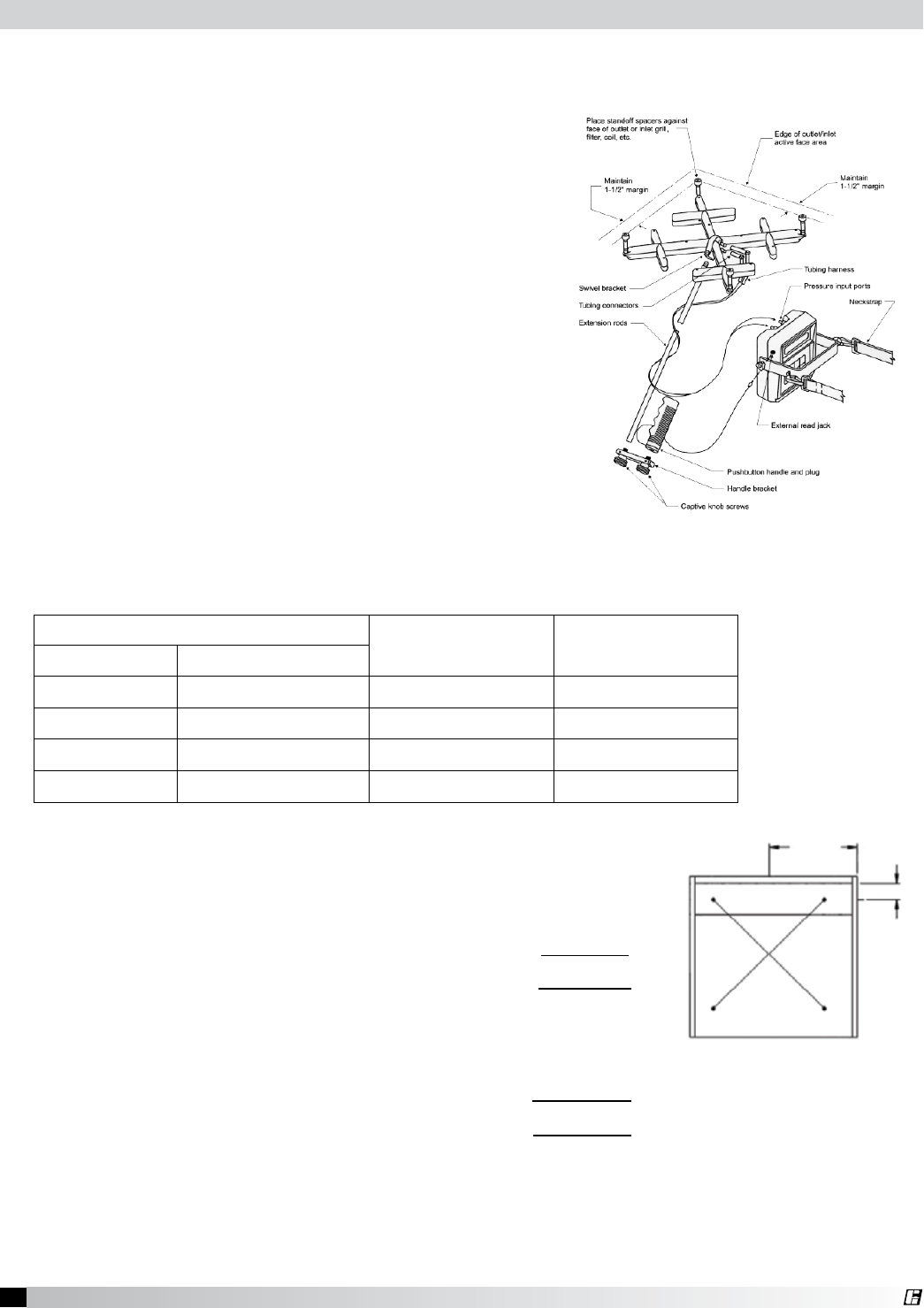
External Supply
Plenum Type
Weight Width Height Length per
section Recommended
Supply Rate
(lbs/ft) (kg/ft) (in) (mm) (in) (mm) (ft) (m)
Back Supply 35.0 15.878 6 152.4 Variable Variable 3 to 16 .91 to
4.88
145 cfm/ft
(246.36 m3/hr)
Air Curtain Supply
•14inch 9.5 4.31 14 355.6 10 254 3 to 16 .91 to
4.88
110 cfm/ft
(186.89 m3/hr)
Air Curtain Supply
•24inch 12.5 5.67 24 609.6 10 254 3 to 16 .91 to
4.88
145 cfm/ft
(246.36 m3/hr)
Variable Supply 16.0 7.26 12 304.8 18 457.20 3 to 16 .91 to
4.88
curtain 0-80 cfm/ft
(0-135.92 m3/hr)
face 80-160 cfm/ft
(135.92 -271.84 m3/hr)
Horizontal Supply 14.0 6.35 12 304.8 18 457.20 3 to 16 .91 to
4.88
150 cfm/ft
(254.85 m3/hr)
10 Canopy Hood
®
• ThesefastenersaretohelpmaintainthelocationoftheBackSupply,andarenotintendedto
hold the weight of the Back Supply Unit.
• Thefastenersshouldnotinterferewiththeremovableairdiffusers.
• The31.25in.(79.375cm)heightisbaseduponthecanopyhoodhangingheightof78in.
(198.12 cm) from the finished floor to the bottom of the hood.
L (MODULE LENGTH)
L/2
L/2
L/2
L (MODULE LENGTH)
L/4
L/4
STEP 1
CENTERED ON WIDTH OF THE SUPPLY,
CUT (2) 4 in. X 24 in. OPENINGS AT
THE SUGGESTED LOCATIONS ABOVE
(IF MODULE > 6 ft.)
THE SUGGESTED LOCATION ABOVE
CUT (1) 4 in. X 24 in. OPENING AT
CENTERED ON WIDTH OF THE SUPPLY,
(IF MODULE < 6 ft.)
STEP 1
4 in. TO 6 in.
FASTEN WITH SCREWS, OR TACK WELDS EVERY
PLACE THE DUCT COLLAR OVER THE OPENING,
STEP 2
Fig. 13
• The4in.(10.16cm)
high duct collar is to
be attached to the
back supply.
5. Hang the back supply plenum from the ceiling.
(The back supply plenum needs to be mounted 31.25 in. (79.375 cm) above the floor (based upon a
canopy hood that will be hung at 78 in. (198.12 cm) above the finished floor. This is measured from
the lowest rear edge of the back supply plenum to the finished floor. Leave 6 to 10 in. (15.24 to
25.4 cm) of space below the plenum for access to the air diffusers.)
6. Fasten the Back Supply to the wall, going through the lower Back Supply wall. (Fig. 15)
L (MODULE LENGTH)
L/2
L/2
L/2
L (MODULE LENGTH)
L/4
L/4
STEP 1
CENTERED ON WIDTH OF THE SUPPLY,
CUT (2) 4 in. X 24 in. OPENINGS AT
THE SUGGESTED LOCATIONS ABOVE
(IF MODULE > 6 ft.)
THE SUGGESTED LOCATION ABOVE
CUT (1) 4 in. X 24 in. OPENING AT
CENTERED ON WIDTH OF THE SUPPLY,
(IF MODULE < 6 ft.)
STEP 1
4 in. TO 6 in.
FASTEN WITH SCREWS, OR TACK WELDS EVERY
PLACE THE DUCT COLLAR OVER THE OPENING,
STEP 2
Fig. 12
Fig. 14
Installing the Back Supply Plenum
Hanging the Back Supply Plenum
Installing the Supply Duct Collar
1. Find the center of the back supply plenum.
2. If the back supply plenum is less than 9 ft. 10 in. (299.72 cm) long,
cut opening at the suggested location, centering the opening over
the center of the back supply plenum. (Fig. 12)
3. If the back supply plenum is greater than 9 ft. 10 in. (299.72 cm)
long, divide the length of the back supply by four. This will give you
the center of each half. Cut openings at the suggested location,
centering the duct collar over the center measurement of each half.
(Fig. 13)
4. Place the duct collar(s) over the opening, fastening with screws or
tack-welds every 4 to 6 in. (10.16 to 15.24 cm). (Fig. 14)
L (MODULE LENGTH)
L/2
L/2
L/2
L (MODULE LENGTH)
L/4
L/4
STEP 1
CENTERED ON WIDTH OF THE SUPPLY,
CUT (2) 4 in. X 24 in. OPENINGS AT
THE SUGGESTED LOCATIONS ABOVE
(IF MODULE > 6 ft.)
THE SUGGESTED LOCATION ABOVE
CUT (1) 4 in. X 24 in. OPENING AT
CENTERED ON WIDTH OF THE SUPPLY,
(IF MODULE < 6 ft.)
STEP 1
4 in. TO 6 in.
FASTEN WITH SCREWS, OR TACK WELDS EVERY
PLACE THE DUCT COLLAR OVER THE OPENING,
STEP 2
11 Canopy Hood
®
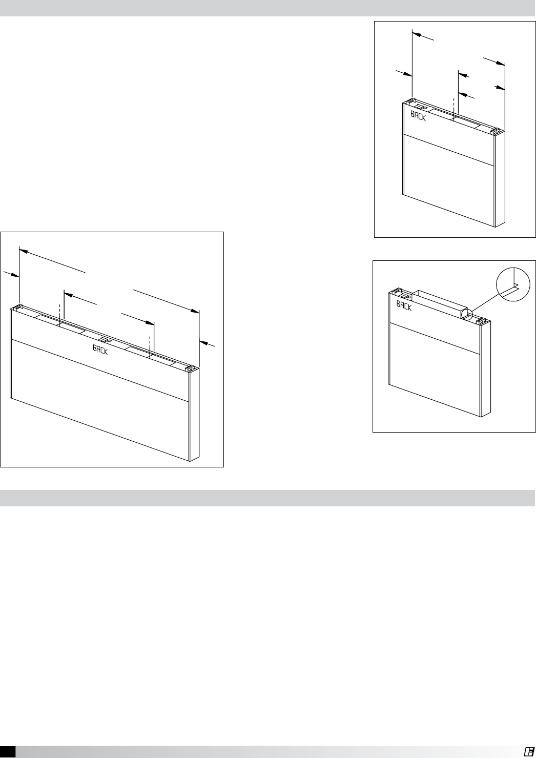
Before hanging the hood according to the
hood installation instructions, please check the
following:
1. Make sure the back supply plenum is
properly secured, as described in steps 5
and 6, page 10.
2. If the ductwork for the back supply will not
interfere with the hood installation, it should
be connected now.
3. Any filler panels should be attached to the
hood before the hood installation.
See page 5 for instructions.
4. Lift the hood, and position it so the filler
panels are resting lightly on the top outside
edges of the back supply. The back supply
is used to position the hood only, it is not
intended to hold any hood weight. (Fig. 16)
5. Connect the remaining ductwork for the
back supply and the hood. It is recommended
that caulk be applied at the mating seams
and surfaces of the back supply, the hood,
and the wall.
HANG THE HOOD
EYEBROW STYLE HOOD
CANOPY STYLE HOOD
INSTRUCTIONS, THE HOOD MAY BE FASTENED TO THE BACKSUPPLY.
SEAMS/SURFACES OF THE BACKSUPPLY, THE HOOD, AND THE WALL.
5. CONNECT REMAINING DUCTWORK FOR THE BACKSUPPLY AND THE
HOOD. CAULK IS RECOMMENDED TO BE APPLIED AT THE MATING
4. LIFT THE HOOD; POSITION IT SO THE TOP OF THE
HOOD IS LEVEL WITH THE TOP OF THE BACKSUPPLY; AFTER
THE HOOD IS HUNG FROM THE CEILING AS PER IT'S INSTALLATION
1. THE HOOD IS TO BE HUNG AS PER THE HOODS INSTALLATION
SHOULD BE CONNECTED BEFORE THE HOOD IS HUNG.
3. DUCTWORK FOR THE BACKSUPPLY; IF IT WILL NOT INTERFERE,
2. BEFORE THE HOOD IS HUNG THE BACKSUPPLY MUST BE SECURED
INSTRUCTIONS AND THE FOLLOWING.
PROPERLY, AS DESCRIBED IN "STEP 3 in.
STEP 4
Fig. 16
STEP 5
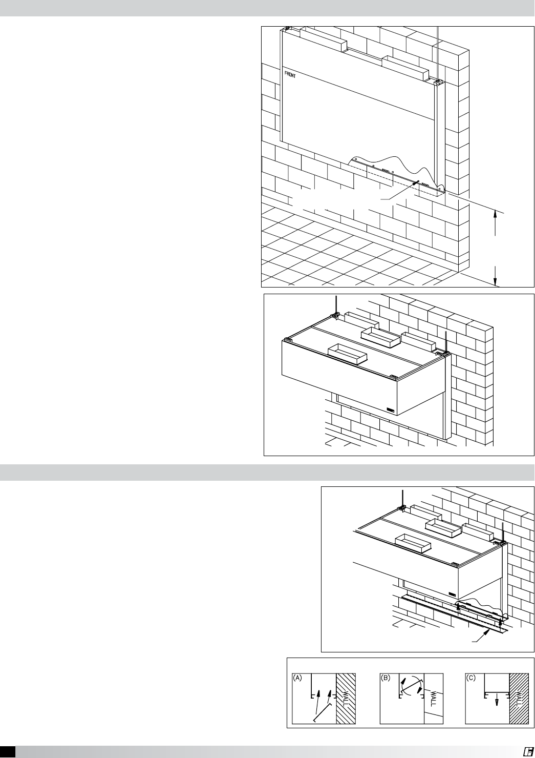
Air Diffusers
(A) Insert the air diffusers at an angle from the bottom.
(B) Rotate the diffusers so the forms are downward.
(C) Rest the diffuser on the internal angles.
Canopy Style Hood
Proximity Style Hood
Removable Air Diffusers
The air diffusers, located at the bottom of the back
supply (Fig. 17), will need to be cleaned as often as the
application dictates. Inspect periodically to determine
the cleaning schedule.
1. To clean the air diffusers, unfasten the screws.
Remove the air diffusers from the Back Supply
Unit, and wash in the sink or dishwasher.
2. Insert the air diffusers at an angle from the bottom,
and rotate so the forms are downward. Rest the
diffuser on the internal angles. (Fig. 18)
3. Refasten with the stainless steel screws.
Fig. 17
STEP 5
Air Diffusers
(A) Insert the air diffusers at an angle from the bottom.
(B) Rotate the diffusers so the forms are downward.
(C) Rest the diffuser on the internal angles.
Canopy Style Hood
Proximity Style Hood
Removable Air Diffusers
Fig. 18
Air Diffusers
Hanging the Hood
STEP 3 Furnished by Others
0.500 in. Threaded &
0.500 in. Threaded Nuts
(Furnished by Others)
Hanger Bracket Detail
1) Hang Backsupply Modules from the
ceiling (the example shows the module
being supported with threaded rod)
The backsupply is to be 31.25 in. from the
floor. This is measured from the lowest
rear edge of the backsupply module to the
finished floor.
2) Fasten backsupply to wall through the
lower backsupply wall. These fasteners
are to help maintain location of the
backsupply, and are NOT intended to hold
any weight of the unit. Fasteners should
not interfere with the removable air diffuser.
31.25 in.
Critical
Dimension
Fasteners holding the
back supply to the wall
Fig. 15
12 Canopy Hood
®
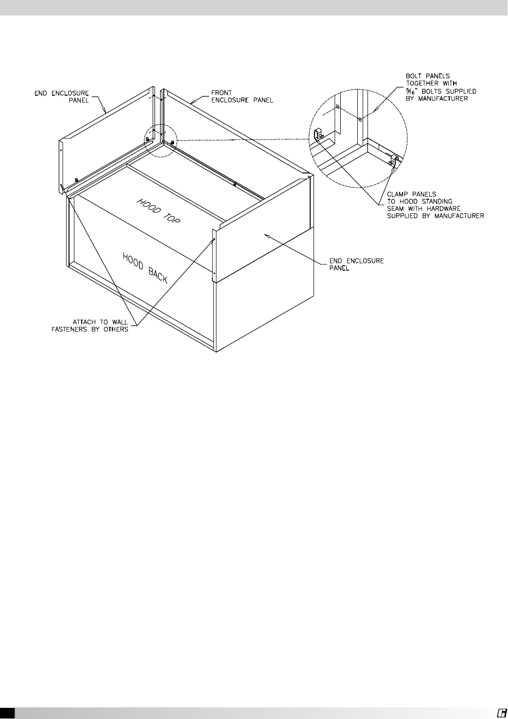
Before installing the enclosure panels, make sure the hood is hung in position with all the ductwork
attached and electrical connections completed.
1. Position the end enclosure panels on the hood, and clamp into place with clamps provided or tack-
weld the panels into place (Fig 19).
2. Fasten the end enclosure panels to the wall, method depends on wall construction. (fasteners are
not provided)
If the hood is a double island, bolt the end enclosure panels together. (fasteners are not provided)
3. Position the front enclosure panel(s) on the hood, and bolt to the end enclosure panels with the
5/16 in. bolts provided in the hardware package.
4. Tack-weld or clamp the front enclosure panel(s) to the hood. If clamps are used, they must be
positioned 4 in. (100 mm) from the ends, and in the center of the front enclosure panel.
5. To allow for ease of cleaning, caulk the external seams with NSF Approved silicone caulk
(GE SCS1009, or its equivalent). The caulk is not provided.
6. Installation instructions may not be applicable for concrete ceilings.
Fig. 19
Installing Enclosure Panels
13 Canopy Hood
®
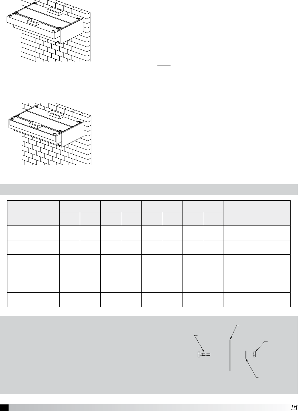
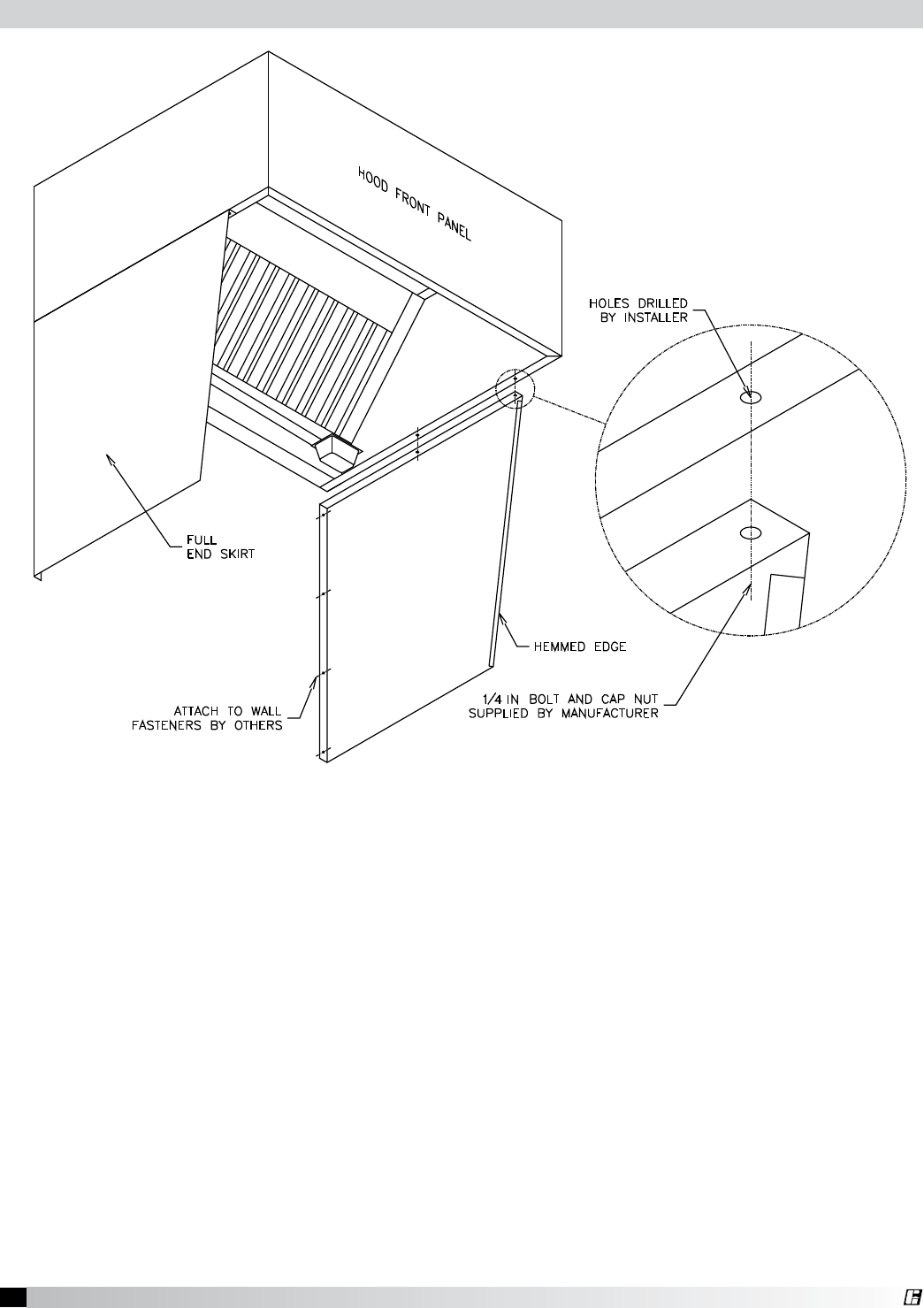
Fig. 20
1. After the hood is hung in position, slide the hemmed form on top of the end skirt onto the end
panels of the hood.
2. Drill a hole in the hood end panel to line up with the hole in the end skirt. Attach the end skirt with
a 1/4 in. bolt and cap nut to the inside of the hood, or tack-weld the end skirt to the hood.
3. Position the end skirt against the wall and attach. The method depends on the wall construction.
(fasteners for this are not provided)
4. Caulk the internal joint formed by the end skirt and the hood end panel with NSF Approved silicone
caulk (GE SCS1009 or its equivalent). The caulk is not provided.
5. To allow for ease in cleaning, also caulk all the external seams.
Installing End Skirts
.
14 Canopy Hood
®
Fig. 21
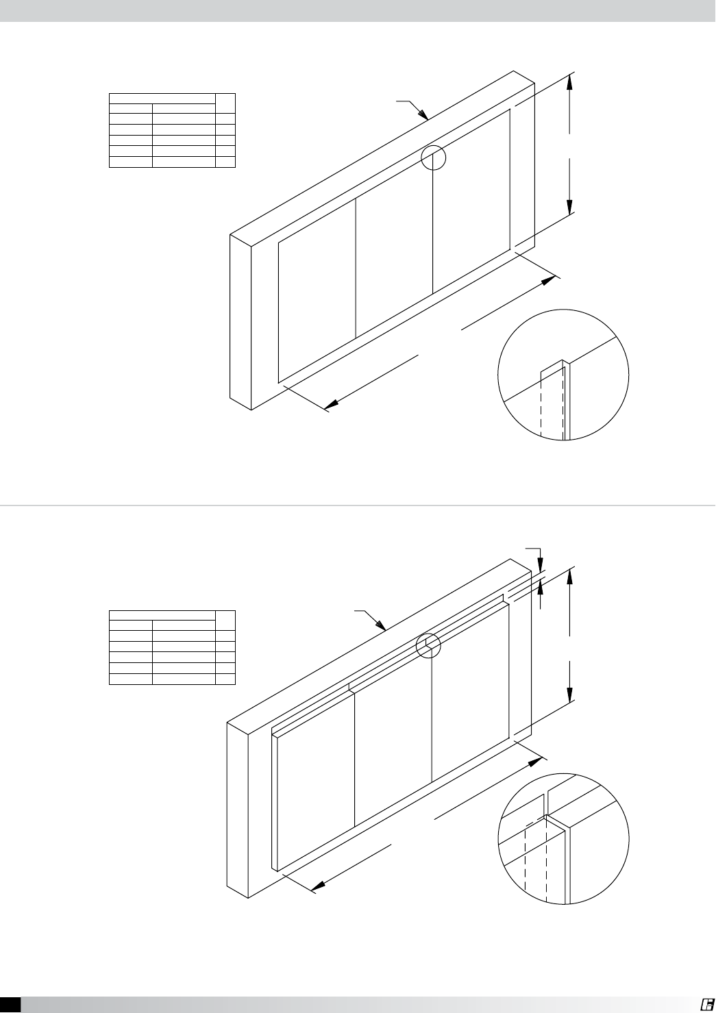
Installing Backsplash Panels
MATERIAL GAUGE — STAINLESS
MATERIAL GAUGE — STAINLESS
INSULATION — 1 IN. (25.4 MM)
FLAT BACKSPLASH PANEL
INSULATED BACKSPLASH PANEL
WALL
WALL
NOTE: PANELS UP TO 46 IN. (1168.4 MM) WIDE SHIP IN ONE PIECE; OVER 46 IN. (1168.4 MM) IN MULTIPLE PIECES.
NOTE: PANELS UP TO 48 IN. (1219.2 MM) WIDE SHIP IN ONE PIECE; OVER 48 IN. (1219.2 MM) IN MULTIPLE PIECES.
LENGTH
1 IN. (25.4 MM)
HEIGHT
LENGTH
HEIGHT
LENGTH QTY
Inches Millimeters
<= 48 <= 1219.2 1
>48<=94 >1219.2<=2387.6 2
>94<=141 >2387.6<=3581.4 3
>141<=188 >3581.4<=4775.2 4
>188<=235 >4775.2<=5969 5
LENGTH QTY
Inches Millimeters
<= 46 <= 1168.4 1
>46<=91 >1168.4<=2311.4 2
>91<=136 >2311.4<=3454.4 3
>136<=181 >3454.4<=4597.4 4
>181<=226 >4597.4<=5740.4 5
Fig. 22
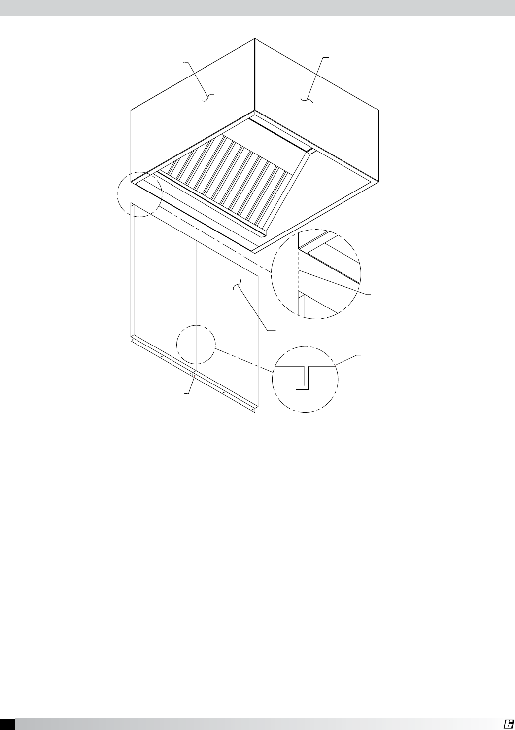
15 Canopy Hood
®
1. After the hood is hung in position, slide the flat flange of the backsplash panel behind the back of
the hood.
Note: If the backsplash panel length is greater than 46 in. (116.84 cm), it will be shipped in multiple
pieces.
2. After the backsplash panel has been positioned, drill holes in the panel and fasten to the wall.
(fasteners provided by others).
Note: The holes should be spaced to adequately secure the panel to the wall.
3. Caulk the joints between the hood and the backsplash panel with NSF Approved silicone caulk
(GE SCS1009, or its equivalent). The caulk is not provided.
4. Caulk the joint between the backsplash panels when multiple panels are required, with NSF
Approved silicone caulk (GE SCS1009, or its equivalent). The caulk is not provided.
H
O
LE
S
S
H
OU
LD BE
S
PA
C
ED T
O
A
DE
Q
UATELY SECURE THE PANE
L
TO THE WALL STUDS
(
HOLE SPACIN
G
A
ND FASTENERS PROVIDED BY OTHERS
)
BA
C
K
S
PLA
S
H PANE
L
HOOD END PANEL
L
H
OO
D FR
O
NT PANE
L
S
LIDE FLAN
GE
BEHIND BA
CK
O
F THE H
OOD
S
E
C
TI
O
N VIE
W
O
F BA
C
K
S
PLA
SH
PANEL
O
VERLA
P
Fig. 23
Installing Backsplash Panels
16 Canopy Hood
®
HOOD SECTION VIEW
DEFLECTOR TO BE PLACED CENTERED
UNDER THE SUPPLY DUCT COLLAR
SU
PPL
Y
FIRE DAMPER
INTERNAL
SU
PPL
Y
C
HAMBE
R
H
OO
D
IN
SU
LATE
D
SU
PPLY PLEN
UM
EXHA
UST
C
APT
U
RE
SU
PPLY L
OC
ATI
O
N DETAIL F
OR
A
IR
CU
RTAIN AND
CO
MBINATI
ON
Hanger Bracket
Exhaust Plenum
Duct Cut Out Area
Duct Cut Out Area
Supply Plenum
Hood Length
Hood Width
Front of Hood
Exhaust Plenum
8.00 8.00
8.00
3.00
3.00
16.00
14.00
8.00
1.00
12.00
A
C
O
N
T
INU
O
U
S
L
I
Q
UID
T
I
G
H
T
W
E
L
D
T
O
H
OO
D.
E
X
H
A
U
S
T
DUC
T
C
O
NN
E
C
T
I
O
N I
S
T
O
B
E
C
O
NN
E
C
T
I
O
N
E
X
H
A
U
S
T
DUC
T
F
R
O
N
T
O
F
H
OO
D
H
A
N
G
E
R
BR
A
C
K
E
T
E
X
H
A
U
S
T
P
L
E
NUM
E
X
H
A
U
S
T
P
L
E
NUM
S
UPP
L
Y
P
L
E
NUM
DUC
T
CU
T
O
U
T
A
R
E
A
LABELED SUB-ASSEMBLY FOR EXHAUST HOOD WITHOUT EXHAUST DAMPER PART NO. DC.
2. U.L. LISTED HOOD ASSEMBLY TO BE USED ONLY WITH GREENHECK FAN CORP.
CENTER OF HOOD LENGTH TO CENTER OF DUCT CONNECTION.
NOTES: 1. EXHAUST DUCT CONNECTION TO BE LOCATED WITH IN 48" FROM
1
"
T
O
2
"
T
A
C
K
S
O
R
S
H
EE
T
M
E
T
A
L
S
C
R
E
W
S
A
T
3
"
T
O
6
"
S
P
A
CIN
G
T
O
H
OO
D.
S
UPP
L
Y
DUC
T
C
O
NN
E
C
T
I
O
N
T
O
B
E
T
A
C
K
W
E
L
D
E
D WI
T
H
C
O
NN
E
C
T
I
O
N
S
UPP
L
Y
DUC
T
DUC
T
CU
T
O
U
T
A
R
E
A
Hanger Bracket
Exhaust Plenum
Duct Cut Out Area
Duct Cut Out Area
Supply Plenum
Hood Length
Hood Width
Front of Hood
Exhaust Plenum
8.00 8.00
8.00
3.00
3.00
16.00
14.00
8.00
1.00
12.00
Back View of the Hood Fig 25
Fig. 26 Fig. 27
Fig. 28
Note: UL listed hood
assembly to be used
only with Greenheck
Fan Corp. labeled
subassembly for
exhaust hood without
exhaust damper part
Number DC.
Hood Top
1. The exhaust duct
connection needs to
be located within 48 in.
(121.92 cm) from the
center of the hood
length to the center of
the duct connection.
(see Fig. 24, back view
Fig. 25)
2. The exhaust duct
connection is to be
a continuous liquid-
tight weld. Weld with
a non-ferrous filler
wire, such as silicon
bronze or stainless
steel filler wire. Protect
all stainless steel areas
from weld splatter.
3. The supply duct
connection is tack-
welded at 1 to 2 in.
(2.54 to 5.08 cm)
intervals, or sheet metal
screws at 3 to 6 in.
(7.62 cm to 15.24 cm)
spacing to the hood.
(Fig. 26)
4. The deflector is
centered under the
supply duct collar.
(Fig. 28)
5. For hoods that are
insulated, the edges of
the insulation need to
be taped after the hole
is cut, (the insulation
tape is to be provided
by others).
6. On combination hoods,
make sure the fire
damper is located over
the internal supply
chamber. (Fig. 29)
Top View of the Hood Fig. 24
Installing Duct Collars
17 Canopy Hood
®
This is a guide to assist in determining if multiple hoods on one fan can be balanced to have equal
static pressure. For multiple hoods on one fan to achieve their designed exhaust flow, all of the hoods
must have equal static pressure at their designed exhaust flow.
The laws of physics force the static pressure for each branch of a duct system on one fan to always be
equal. This will happen by the flow rate increasing in low static branches and decreasing in high static
branches until the static pressure is equal in all branches.
Checking for Balance
Every hood with Exhaust Air Balancing Baffles (EABB) has a range for its static pressure. The low
number in this range is given by the standard calculation for hood static. (Static that is printed with
the CAPS submittal). The maximum increase above the low number can be calculated from the duct
velocity at the low static, (also given on CAPS submittal). This is then added to the low number to get
the highest static pressure possible with an EABB.
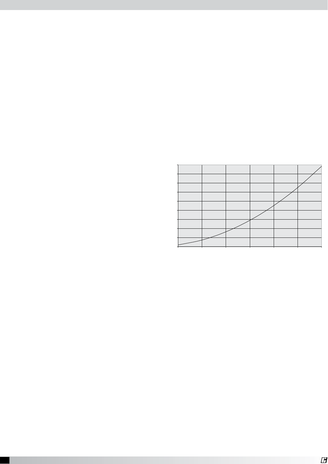
The maximum potential increase in static is given in the graph, or can be calculated from:
Max. Increase = 0.00000036 x (Duct velocity)2
After the range for each hood is calculated,
it should be compared to the hood with the
highest static pressure. If the highest hood
falls inside of the range, then the hoods can be
balanced with the EABB. If it is higher than the
range, the hoods cannot be balanced.
Example 1:
Hood 1: Ps = 0.58 in. wg
Duct Velocity = 1900 FPM
Hood 2: Ps = 0.44 in. wg
Duct Velocity = 1800 FPM
Hood 2 has the lower Ps, at 1800 FPM the maximum increase in Ps is 1.17. The range for Hood 2 is
0.44 to 1.61. Hood 1 is less than 1.61 so these hoods can be balanced.
Example 2:
Hood 3: Ps = 2.00 in. wg
Duct Velocity = 2000 FPM
Hood 4: Ps = 0.44 in. wg
Duct Velocity = 1500 FPM
Hood 4 has the lower Ps, at 1500 FPM the maximum increase in Ps is .81. The range for Hood 4 is 0.44
to 1.25. Hood 3 is higher than 1.25 so these hoods cannot be balanced.
Note 1: For many systems, an EABB may not be needed on the hood that has the highest static pressure. The
exception to this is if the individual ductwork has uneven static pressures.
Note 2: When sizing the fan, use the static pressure from the highest hood and sum the CFM from all the hoods.
Maximum Increase in Static Pressure for Exhaust Air Balancing Baffle
(Fully Closed)
0
0.5
1
1.5
2
2.5
3
3.5
4
4.5
500 1000 1500 20002500 3000 3500
Duct Velocity FPM
Increase in Collar Staitc Pressure
Exhaust Air Balancing Baffles (EABB)
18 Canopy Hood
®
Baffle Filter Style Hoods
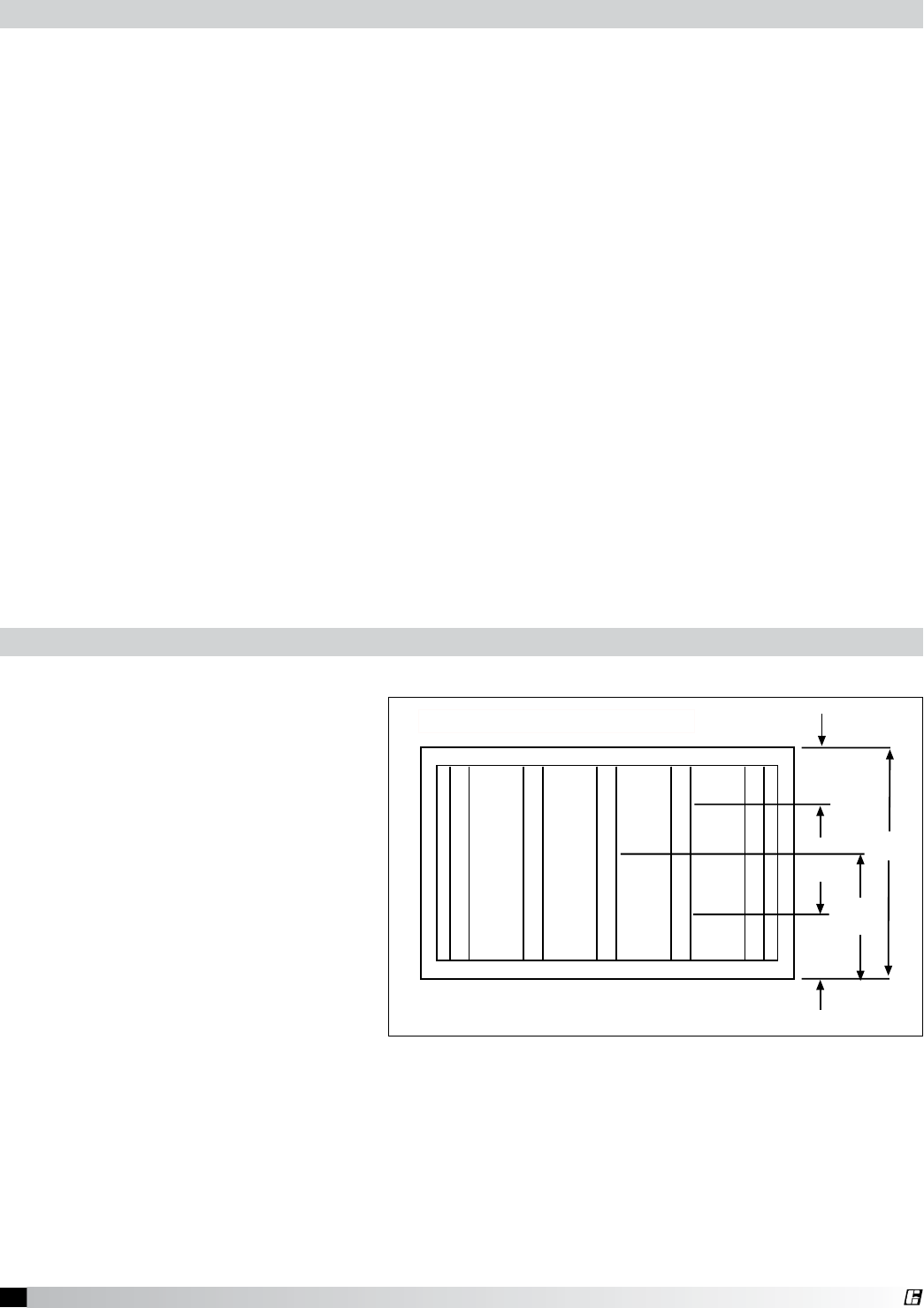
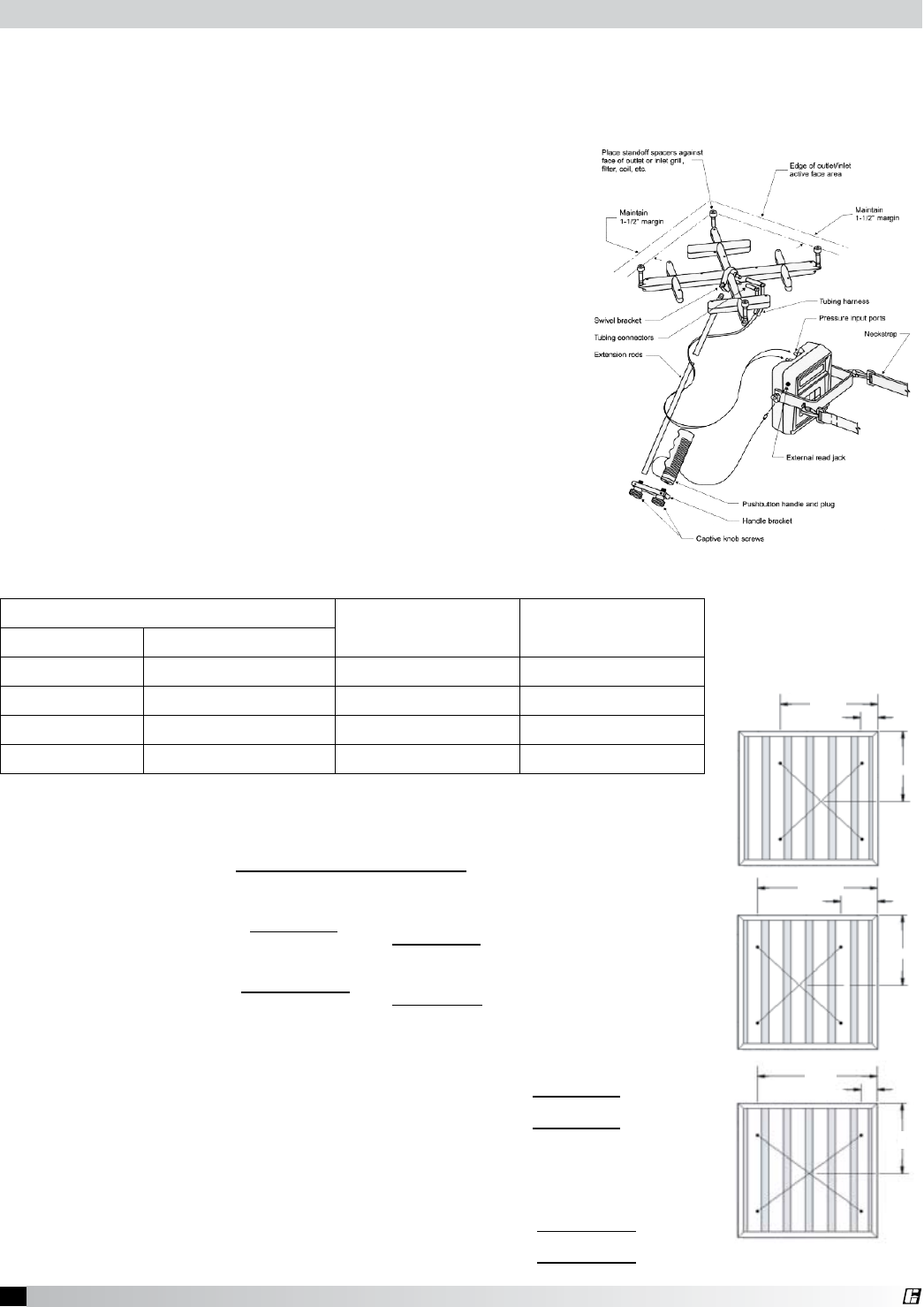
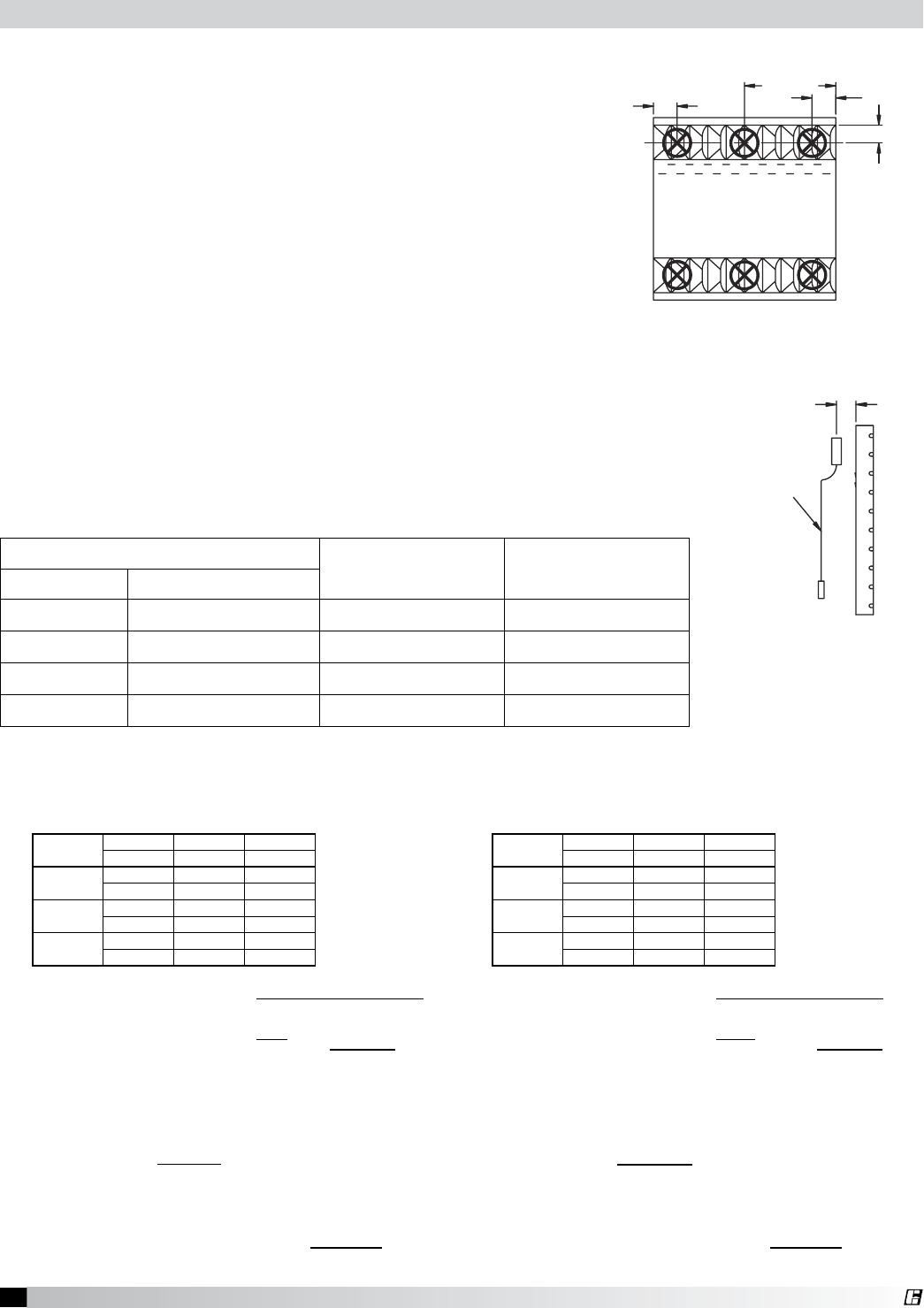
A. Exhaust:
With all the filters in place, determine
the total hood exhaust volume with a
rotating vane anemometer as follows:
1. All cooking equipment should
be on.
2. Measure the velocities
Velocity measurements should
be taken at five locations per
filter. These must be over a filter
slot as in Fig. 29.
x
x
x
x
x
R
o
tat
i
n
g
V
a
n
e
A
n
e
m
o
m
ete
r
A
i
r
f
l
o
w
2
H/4
H/2
H/4
H
Fig. 29
A. To determine the proper dining room air balance:
1. Refer to engineering drawings to determine total exhaust CFM from dining areas.
(Exhaust fans, heating and air conditioning units, restrooms, etc.)
2. Determine the total CFM of make-up air supplied to dining area.
3. Subtract #1 from #2 above. If the result is a negative number, a negative pressure is present
in the dining area. In this case, kitchen exhaust odors could be drawn from the kitchen to the
dining area. Therefore, exhaust or supply air should be adjusted to provide a slight positive
pressure in the dining area.
B. To determine proper kitchen air balance:
1. Refer to engineering drawings to determine total exhaust from the kitchen area.
(Exhaust hoods, dishwasher hoods, etc.)
2. Determine total CFM of make-up air supplied to kitchen area.
(Make-up air hoods, heating and air conditioning units, etc.)
3. Subtract #1 from #2 above. The result should be a negative number. If the result is a positive
number, a positive pressure is present in the kitchen area. Kitchen odors could be forced into
the dining area. Also, a positively balanced kitchen area can adversely affect the performance
of the exhaust hood.
Caution: According to NFPA 96, Ch. 8-3 Replacement Air: Replacement air quantity shall be adequate
to prevent negative pressures in the commercial cooking area(s) from exceeding 4.98 kPa (0.02 in.
water column).
Balancing the Kitchen Exhaust System
Testing Hood Air Volume
Nominal Filter Size
19 Canopy Hood
®
255
(4663.44 m/h)
248
(4535.42 m/h)
256
(4681.73 m/h)
240
(4389.12 m/h)
250
(4572 m/h)
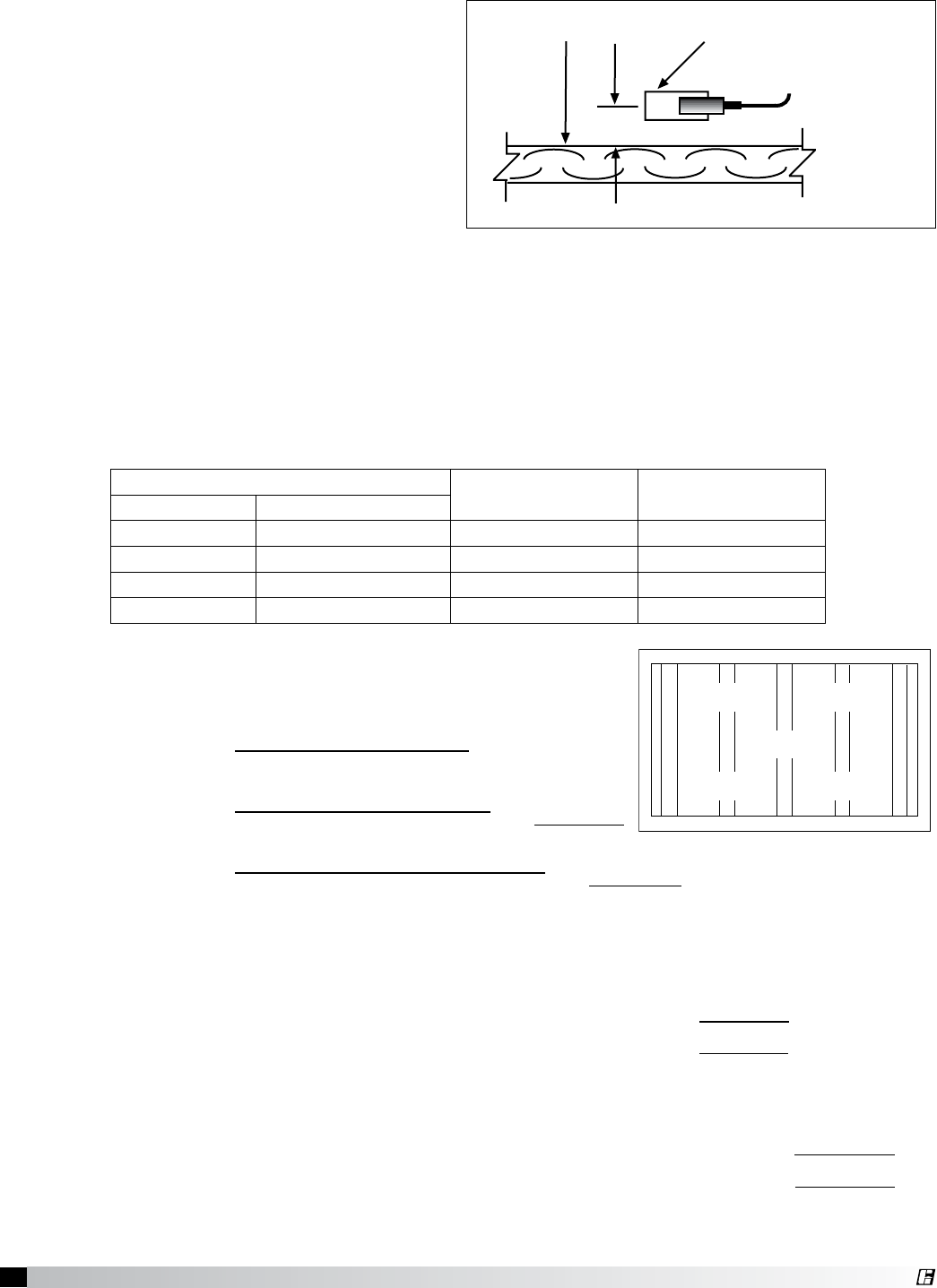
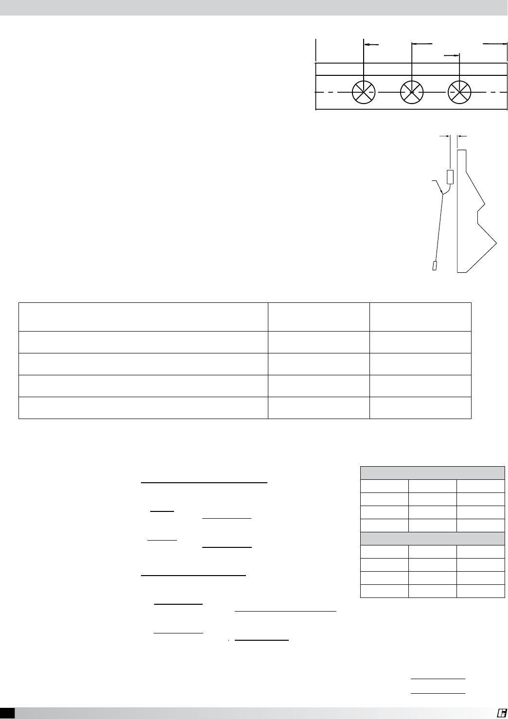
Measure the velocity of each location.
A digital 2.75 in. (70 mm) rotating
vane anemometer or equivalent
is suggested. The center of the
anemometer should be held 2 in.
(50 mm) from the face of the filters as
shown in Fig. 30. It is helpful to make
a bracket to keep the anemometer
at the 2 in. (50 mm) distance and
parallel to the filter. Both squareness
and distance are very important for
accuracy.
Calculate the average velocity for the filter.
3. Determine the filter’s conversion factor from the table.
4. Calculate the filter’s volume in CFM (m3/hr) by multiplying the average velocity by the
conversion factor.
5. Calculate the hood’s volume by repeating the process for the remaining filters and summing the
individual filter volumes.
x
x
x
x
x
2 in.
H/4
H/2
H/4
H
Airflow
Rotating Vane Anemometer
Fig. 30
Nominal Filter Size (H x L) Imperial
Conversion Factor
Metric
Conversion Factor
Inches Millimeters
16 x 16 400 x 400 1.63 .157
16 x 20 500 x 400 2.13 .198
20 x 16 400 x 500 1.90 .177
20 x 20 500 x 500 2.48 .230
Total hood volume = (Filter 1 Volume) + (Filter 2 Volume) + (Filter 3 Volume)
= 474.6 + 455.4 + 470.1 = 1400.1 cfm
= 809 + 880 + 799 = 2488 m3/hr
For a nominal filter size of 20 x 16, the conversion factor is 1.90 Imperial (.177 Metric)
Volume for one filter = Conversion Factor x Average Velocity
= 1.90 x 249.8 fpm = 474.6 cfm
= .177 x 4568 m/hr = 809 m3/hr
Example: Exhaust Only Hood with three 20 x 16 Filters
Measured velocities in fpm for one 20 x 16 Filter
Average Velocity = Sum of Velocity Readings
Number of Readings
(Imperial) =255 + 250 + 256 + 248 + 240
5 =249.8 fpm
(Metric) =4663 + 4572 + 4681 + 4535 + 4389
5 =4568 m/hr
20 Canopy Hood
®
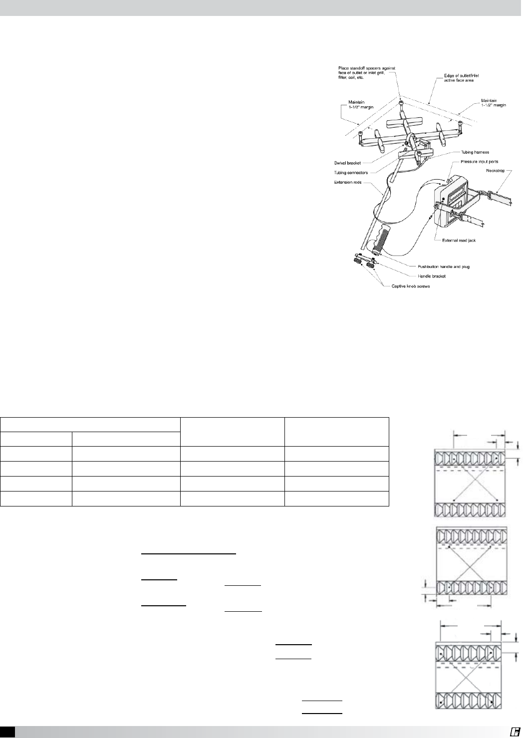
B. Supply (If Applicable):
Example for Perforated Face Supply
1. Hood set up
If the make-up air unit has a temperature control, it should be used to keep the supply air at the
desired room discharge air temperature.
2. Measure Velocities
Divide the perforated face panel into a grid of equal areas, each approximately 4 in. (100 mm)
square.
Measure the velocity at the center of each grid area. A digital 2.75 in. (70 mm) rotating vane
anemometer or equivalent is suggested. The center of the anemometer should be held tight to
the face of the panel, and parallel to the filter. Both squareness and distance are important for
accuracy. Calculate the average velocity of the panel.
3. Measure the length, height, and width of the perforated face panel.
4. Calculate the perforated face panel volume in CFM by using the following formula:
Volume = Avg. Velocity * Length (in.) * Height (in.) * 0.005
Volume = Avg. Velocity * Length (m) * Height (m) * 0.72
5. Calculate the system’s volume by repeating the process for the remaining panels and adding
the individual panel volumes together.
Total system volume = (Panel 1 Volume) + (Panel 2 Volume) + (Panel 3 Volume)
= 606.4 + 614.3 + 593.8 = 1814.5 cfm
= 1029 + 1044 + 1009 = 3082 m3/hr
Example: Face Supply Hood with three 28 in. (.711 m) Perforated Panels
Measured velocities in FPM for one perforated panel
Average Velocity = Sum of Velocity Readings
Number of Readings
(Imperial) =260 + 250 + … + 265 + 260
28 =270.7 fpm
(Metric) =4755 + 4572 + … + 4846 + 4755
28 =4951 m/hr
Measure Length and Height = 28 in. (.711 m) long perforated panels x 16 in. (.406 m) high
Volume for one panel = Conversion
Factor xAverage
Velocity x Length x Height
= 0.005 x 270.7 fpm x 28 x 16 = 606.4 cfm
= 0.72 x 4951 m/hr x .711 x .406 = 1029 m3/hr
Filter Readings (fpm)
260 250 255 260 250 255 265
270 275 270 280 265 265 270
290 285 280 280 275 290 295
285 275 280 260 270 265 260
Filter Readings (m/hr)
4755 4572 4663 4755 4572 4663 4846
4938 5029 4938 5121 4846 4846 4938
5304 5212 5121 5121 5029 5304 5395
5212 5029 5121 4755 4938 4846 4755
21 Canopy Hood
®
14 in.
17.25 in.
10 in.
2.75 in.
6 in.
2.75 in.
14 in.
Fig. 32
Fig. 33
Fig. 34
Nominal Filter Size (H x L) Imperial
Conversion Factor
Metric
Conversion Factor
Inches Millimeters
16 x 16 400 x 400 1.66 .154
16 x 20 400 x 500 2.10 .195
20 x 16 500 x 400 1.96 .182
20 x 20 500 x 500 2.40 .223
Testing Hood Air Volume
10 in.
10 in.
Baffle Filters Style Hoods with the Shortridge Meter
A. Exhaust
With all the filters in place, determine the total hood exhaust
volume with a Shortridge meter as follows:
1. All cooking equipment should be on. If the hood has
internal short circuit make-up air, it should be turned off.
2. Measuring Velocities
• SetuptheShortridgemeter.
• For20in.(500mm)widefilters,positionthegridas
shown in Fig. 32 and 33. Average two measurements.
• For16in.(400mm)widefilterspositionthegridas
shown in Fig. 34.
• Takevelocityreadingsforeachfilter.
3. *Calculate each filter’s volumetric flow rate by summing
the flow rate of each individual filter in the hood.
4. *Calculate the total hood’s volumetric flow rate by
summing the flow rate of each individual filter in the hood.
*Note: For best accuracy multiply the velocity of each filter by its
conversion factor and sum the flow rates. Averaging the velocity
measured for all filters may cause error.
Example: Measured velocities for 20 x 20 filter = 185 and 189 fpm
Average Velocity = Sum of Velocity Readings
Number of Readings
(Imperial) =185 + 189
2=187.0 fpm
(Metric) =3383 + 3456
2=3420 m/hr
Flow rate for one filter = Conversion
Factor xAverage
Velocity
= 2.40 x 187.0 fpm = 448.8 cfm
= .223 x 3420 m/hr = 763 m3/hr
Total hood flow rate = (Filter 1
Flow Rate) +…+ (Filter X
Flow Rate)
=448.8 + 457.8 + 437.5 + 444.8 = 1788.9 cfm
=763 + 778 + 743 + 756 = 3040 m3/hr
Fig. 31
22 Canopy Hood
®
Rotation Vane
A
nemometer
2 in.
Fig. 35
Fig. 36
Cartridge Filter Size Imperial
Conversion Factor
Metric
Conversion Factor
16 in. (400 mm) high with 4 in. (100 mm) high inlet 1.63 1/ft35.35 1/m3
20 in. (500 mm) high with 4 in. (100 mm) high inlet 2.15 1/ft37.05 1/m3
16 in. (400 mm) high with 7 in. (120 mm) high inlet 1.24 1/ft34.07 1/m3
20 in. (500 mm) high with 7 in. (120 mm) high inlet 1.58 1/ft35.18 1/m3
Filter Readings (fpm)
470 440 425
482 430 453
455 431 441
399 439 465
Filter Readings (m/hr)
8595 8047 7772
8815 7864 8284
8321 7882 8065
7297 8028 8504
High Velocity Cartridge Filters
A. Exhaust
With all the filters in place, determine the total hood exhaust
volume with a rotating vane anemometer as follows:
1. All cooking equipment should be on. If the hood has
internal short circuit make-up air, it should be turned off.
2. Measuring Velocities
• Velocitymeasurementshouldbetakenatthreelocationsperfilter.
These must be over the inlet opening as shown in Fig. 35.
• Measurethevelocityofeachlocation.Adigital2.75in.(70mm)
rotating vane anemometer or its equivalent is suggested. The center
of the anemometer should be held 2 in. (50 mm) from the face of
the filters as in Fig. 31. It is helpful to make brackets to keep the
anemometer at the 2 in. (50 mm) distance and parallel to the filter.
Both squareness and distance are important for accuracy.
3. Calculate the average slot velocity.
4. Calculate the CFM per linear foot by dividing the average velocity by a
conversion factor listed in the following table.
5. Calculate the hood’s exhaust volume by multiplying the CFM per linear
foot by the length of hood.
1/4 Width
1/4 Width
1/2 Width
1/2 Height
Inlet Height
Filter Height
Example:
Measure the slot velocities in fpm for a 9 ft. (2.74 m) hood with four 20 x 20 in. (500 x 500 mm)
filters with standard opening, three readings per filter.
Average slot velocity = Sum of Velocity Readings
Number of Readings
(Imperial) =5330
12 =444.2 fpm
(Metric) =97474
12 =8123 m/hr
CFM per linear foot = Average Slot Velocity
Conversion Factor
=444.2 fpm
2.15 =206.6 cfm/linear foot
=8123 m/hr
7.05
= 1152 m3/hr
Hood exhaust volume = CFM/linear foot (m3/hr / m) x Hood Length
= 206.6 x 9 ft. = 1859.4 cfm
= 1152 x 2.74 m = 3156 m3/hr
23 Canopy Hood
®
1/2 width
1/2 height
Fig. 38
Nominal Filter Size (H x L) Imperial
Conversion Factor
Metric
Conversion Factor
Inches Millimeters
16 x 16 400 x 400 1.22 ft2.113 m2
16 x 20 400 x 500 1.67 ft2.155 m2
20 x 16 500 x 400 1.21 ft2.112 m2
20 x 20 500 x 500 1.50 ft2.139 m2
High Velocity Cartridge Filters
A. Exhaust
With all the filters in place, determine the total hood exhaust
volume with a Shortridge meter as follows:
1. All cooking equipment should be on. If the hood has
internal short circuit make-up air, it should be turned off.
2. Measuring Velocities
• SetuptheShortridgemeter.Leaveallholesof
Velgrid open. Do NOT tape over holes that are not
over openings. The conversion factor takes this into
account.
• Positionthegridovereachfilterasshown.
• Takevelocityreadingsforeachfilter.
3. *Calculate each filter’s volumetric flow rate by summing
the flow rate of each individual filter in the hood.
4. *Calculate the total hood’s volumetric flow rate by
summing the flow rate of each individual filter in the
hood.
*Note: For best accuracy multiply the velocity of each filter
by its conversion factor and sum the flow rates. Averaging the
velocity measured for all filters may cause error.
Fig. 37
Total hood flow rate = (Filter 1 Flow Rate) + … + (Filter X Flow Rate)
=423.0 + 421.8 + 420.7 + 418.2 = 1683.7 cfm
Flow rate for one filter = Conversion
Factor xAverage
Velocity
(Imperial) = 1.50 x 282 fpm = 423.0 cfm
(Metric) = .139 x 5157 m/hr = 717 m3/hr
Example: Measured velocities for 20 x 20 filter = 282 fpm (5157 m/hr)
=717 + 717 + 715 + 711 = 2860 m3/hr
24 Canopy Hood
®
A. Exhaust
With all the filters in place, determine the total hood exhaust
volume with a rotating vane anemometer as follows:
1. All cooking equipment should be off. If the hood has internal
short circuit make-up air, it should be turned off.
2. Measuring Velocities
• Measurementshouldbetakenatsixlocationsperfilter.
They must be over the inlet opening as shown in Fig. 39.
• Measurethevelocityofeachlocation.Adigital2.75in.
(70 mm) rotating vane anemometer or its equivalent is
suggested. The center of the anemometer should be held 2 in. (50 mm) from the face of the
filters as in Fig. 40. It is helpful to make brackets to keep the anemometer at the 2 in. (50 mm)
distance and parallel to the filter. Both squareness and distance are important for accuracy.
3. Calculate the average velocity for the filter.
4. Determine the filter’s conversion factor from the table.
5. Calculate each filters volume in CFM by multiplying the average
velocity by the conversion factor.
2 in.
Rotating Vane
Anemometer
1/2 Width
1/4 Width
1/4 Width
1/2 Height
Fig. 40
Nominal Filter Size (H x L) Imperial
Conversion Factor
Metric
Conversion Factor
Inches Millimeters
16 x 16 400 x 400 1.31 ft2.122 m2
16 x 20 400 x 500 1.65 ft2.153 m2
20 x 16 500 x 400 1.23 ft2.114 m2
20 x 20 500 x 500 1.65 ft2.153 m2
Grease-X-Tractor™ High Efficiency Filters or Grease Grabber™ Multi-Filtration System
2 in.
Rotating Vane
Anemometer
1/2 Width
1/4 Width
1/4 Width
1/2 Height
Fig. 39
Filter 1 225 201 187
210 238 197
Filter 2 228 222 226
237 240 220
Filter 3 230 245 240
250 223 219
Filter 4 225 265 219
245 221 200
Average slot velocity for Filter 1 = Sum of Velocity Readings
Number of Readings
=1258
6 = 209.7 fpm
(repeat for each filter)
For a nominal filter size of 20 x 20, the conversion factor is 1.65
Volume for Filter 1 = Conversion Factor x Average Velocity
= 1.65 ft2x 209.7 ft./min.
=346.0 cfm (repeat for each filter)
Example: (Imperial)
Hood Length = 7 feet 0 inches with four 20 x 20 filters.
Measure the velocities in fpm for each 20 x 20 filter
(six readings per filter)
Total hood volume
=Filter 1
Volume +Filter 2
Volume +Filter 3
Volume +Filter 4
Volume
= 346.0 + 377.6 + 386.9 + 378.1 = 1488.6 cfm
Filter 1 4114.80 3675.88 3419.86
3840.48 4352.54 3602.74
Filter 2 4169.66 4059.94 4133.08
4334.26 4389.21 4023.36
Filter 3 4420.12 4480.56 4389.12
4572.00 4078.22 4005.07
Filter 4 4114.80 4846.52 4005.07
4480.56 4041.65 3657.60
Example: (Metric)
Hood Length = 2.13 meters, with four 500 x 500 mm filters.
Measure the velocities in m/hr for each 500 x 500 mm filter
(six readings per filter)
Average slot velocity for Filter 1 = Sum of Velocity Readings
Number of Readings
=23006
6 = 3834 m/hr
(repeat for each filter)
For a nominal filter size of 500 x 500, the conversion factor is .153
Volume for Filter 1 = Conversion Factor x Average Velocity
= .153 m2x 3834 m/hr
=586.7 m3/hr (repeat for each filter)
Total hood volume
=Filter 1
Volume +Filter 2
Volume +Filter 3
Volume +Filter 4
Volume
= 587 + 642 + 657 + 642 = 2528 m3/hr
25 Canopy Hood
®
14.25 in.
2.75 in.
2.75 in.
2.5 in.
3.25 in.
14.75 in.
14.25 in.
2.75 in.
2.75 in.
Fig. 42
Fig. 44
Fig. 43
Nominal Filter Size (H x L) Imperial
Conversion Factor
Metric
Conversion Factor
Inches Millimeters
16 x 16 400 x 400 1.53 ft2.142 m2
16 x 20 400 x 500 2.00 ft2.185 m2
20 x 16 500 x 400 2.25 ft2.209 m2
20 x 20 500 x 500 3.00 ft2.279 m2
Grease-X-Tractor™ High Efficiency Filters or Grease Grabber™ Multi-Filtration System
A. Exhaust
With all the filters in place, determine the total hood exhaust
volume with a Shortridge meter as follows:
1. All cooking equipment should be on. If the hood has
internal short circuit make-up air, it should be turned off.
2. Measuring Velocities
• SetuptheShortridgemeter.Leaveallholesof
Velgrid open. Do NOT tape over holes that are not
over openings. The conversion factor takes this into
account.
• For20in.(500mm)highfilters,positionthegrid
as shown in Fig. 42 and 43. Average the two
measurements.
• For16in.(400mm)highfilterspositionthegridas
shown in Fig. 44.
• For20in.(500mm)widefilters,positionthegridover
the left and right side of the filter. Average the two
measurements.
• Takevelocityreadingsforeachfilter.
3. *Calculate each filter’s volumetric flow rate by summing
the flow rate of each individual filter in the hood.
4. *Calculate the total hood’s volumetric flow rate by summing
the flow rate of each individual filter in the hood.
*Note: For best accuracy multiply the velocity of each filter by its
conversion factor and sum the flow rates. Averaging the velocity
measured for all filters may cause error.
Flow rate for one filter = Conversion Factor x Average Velocity
= 3.0 x 201.5 fpm = 604.5 cfm
= .279 x 3385 m/hr = 944 m3/hr
Total hood flow rate = Filter 1
Flow Rate + … + Filter X
Flow Rate
= 604.5 + 600.3 + 592.4 + 613.3 = 2410.5 cfm
944 + 1020 1006 + 1042 = 4012 m3/hr
Example:
Measured velocities for 20 x 20 in. (500 x 500 mm) filter.
Average slot velocity = Sum of Velocity Readings
Number of Readings
(Imperial) = 198 + 205
2 = 201.5 fpm
(Metric) =3021 + 3749
2 = 3385 m/hr
Fig. 41
26 Canopy Hood
®
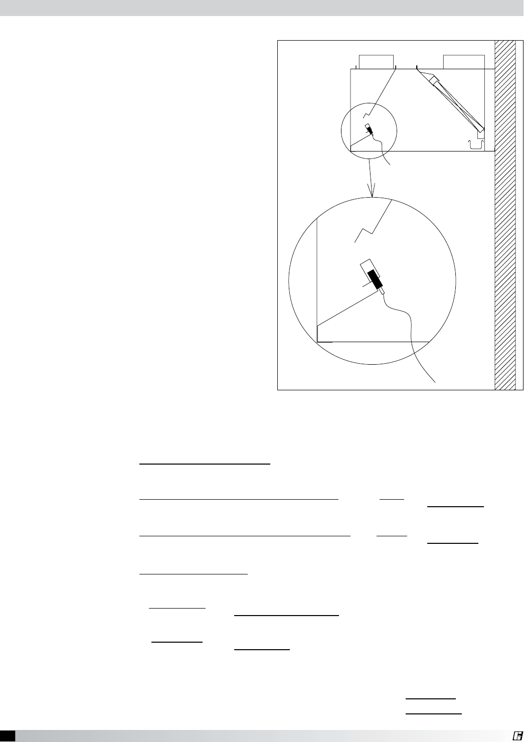
Short Circuit Hoods
A. Supply
All cooking equipment should be off. The hood
exhaust should also be off.
1. Measuring Velocities
• Velocitymeasurementsshouldbemade
with a digital 2.75 in. (70 mm) rotating vane
anemometer or its equivalent.
• Onevelocitymeasurementshouldbetaken
for every 8 in. (200 mm) of short circuit
opening length, starting tight against one
edge of the opening, and finishing tight
against the other edge. The anemometer
should be placed at the bottom edge of the
opening, flush with the bottom lip as shown
in Fig. 45. Both squareness and placement
are important for accuracy.
2. Calculate the average slot velocity.
3. Calculate the CFM per linear foot by dividing
the average velocity by a conversion factor of
5.52 per ft. or 1.68 per m.
4. Calculate the hoods exhaust volume by
multiplying the CFM per linear foot by the total
hood length.
Fig. 45
Testing Hood Air Volume
Example: 4 ft. (1.22 m) short circuit hood (36 in. (.914 m) short circuit opening):
Number of readings = 36 in. / 8 in. => 6 readings (.914 m / .2 m => 6 readings)
Average slot velocity = Sum of Velocity Readings
Number of Readings
(Imperial) =786 + 900 + 1126 + 1048 + 1111 + 1115
6 =6086
6=1014.3 fpm
(Metric) =1335 + 1529 + 1913 + 1780 + 1888 + 1894
6 =10339
6=1723 m/hr
CFM per linear foot = Average Slot Velocity
Conversion Factor
=1014.3 fpm
5.52 =183.8 cfm/linear foot
=1723 m/hr
1.68 =1026 m3/hr
Hood supply volume = CFM/linear foot (or m3/hr) x Total Hood Length
= 183.8 x 4 ft. = 735.2 cfm
= 1026 x 1.22 m = 1252 m3/hr
27 Canopy Hood
®
POWER SOURCE MANUAL RESET RELAY
MICROSWITCH
MICROSWITCH
ELECTRIC GAS VALVE
INSTALLER PROVIDED JUNCTION BOXES
PRM
BASIC WIRING DIAGRAM
RED (COMMON)
POWER SOURCE
MANUAL RESET RELAY
YELLOW (N.O)
BLACK (N.C.)
GAS VALVE
MICROSWITCH
BASIC WIRING DIAGRAM
RED (COMMON)
MANUAL RESET RELAY
YELLOW (N.O)
BLACK (N.C.)
GAS VALVE
SEE NOTE 3
NOTE: DO NOT USE YELLOW WIRE ON MICROSWITCH IN NORMAL
INSTALLATION. THE YELLOW WIRE IS TO BE USED ONLY FOR
EXTINGUISHER ALARM, LIGHTS, CIRCUITS, ETC.
L1
L2
PUSHBUTTON SWITCH
120V/60HZ
K1
Ka
K1b
CURRENT DRAW MAX:
8A RESISTIVE
8A INDUCTIVE
120VAC
NOTES:
1. DENOTES FIELD INSTALLATION
2. DENOTES FACTORY INSTALLATION
3. GAS VALVE: UL LISTED ELECTRICALLY-OPERATED SAFETY VALVE FOR NATURAL OR LP GAS AS NEEDED OF
APPROPRIATE PRESSURE AND TEMPERATURE RATING, 110V/60HZ OR AMEREX GAS VALVES, PN 12870, 12871,
12872, 12873, 12874, 12875 and 12876.
4. K1a and K1b ARE N.0. WHEN K1 IS DE-ENERGIZED.
Amerex Wiring Plan View
Fig. 46
28 Canopy Hood
®
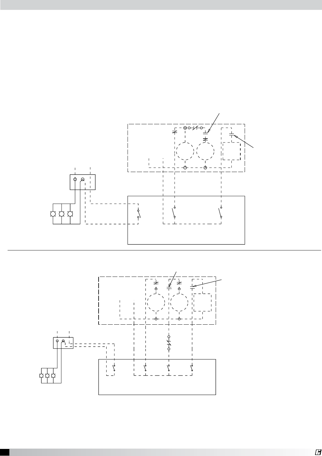
Field Wiring for the Ansul Snap-Action Switch
Option A
Relay Part No. 14702
* K1a and K1b are N.O. when K1 is de-energized
Manual Reset Relay
Part No. 14702
K1*
N.O. K1a
K1b N.O. Push Button
Switch Gas Valve
See Note 3
1
2
3
5
6
7
8
L1
110V/60HZ
Black
Red
Brown
L2
Snap-Action Switch
Part No. 423878
Option B
Relay Part No. 426151
Ansul Snap-Action Switch
(Switch contacts shown with Ansul
Automan in the cocked position)
Snap-Action Switch
Part No. 423878
Black
Red
Brown
L2 Neutral
L1 Hot
110 VAC/60HZ
5
4
3
2
1
GND
Screw
Power
Indicator
Reset
AB
Relay Coil
Manual Reset Relay
(Part No. 426151)
Electrical Rating
1/3 HP, 10 AMP, 120 VAC
1/2 HP, 10 AMP, 240 VAC
13 AMP, 28 VDC
Gas Valve
See Note 3
6
9
3
4
7
1
2 Snap-Action Switches provided by Greenheck
may be wired as shown.
Four typical examples shown
Power to cooking
equipment
Shunt Trip Breaker
120 VAC
NInput
NO
NC Electric gas valve - If reset relay is
used, see option A or B at right.
Mechanical gas shut off valve does not
require electrical connection.
NO
NC
NO
Input
NC
Voltage Free
Contacts for
Building Alarm(s)
Power to
Fan(s)
Fan
Starter
Terminal strip in
Waterwash Control Panel
NO
NC
3
4
5
6
NO
NC
120 VAC
NInput Power to
fan(s)
Fan Starter
Manual Switch
If prohibited by local codes, do not shut down
exhaust fans with this method of wiring.
Note:
1. Denotes field installation.
2. Denotes factory installation.
3. Gas Valves: “UL Listed electrically-operated safety valve for natural or LP gas
as needed of appropriate pressure and temperature rating, 110V/60HZ”
or Ansul gas valves.
4. Do not use black wire on snap-action switch in normal installation. Black
wire may only be used for extraneous alarm, light circuits, etc.
Equipment
Alarms
Waterwash
Fans
Ansul Wiring Plan View
Fig. 47
29 Canopy Hood
®
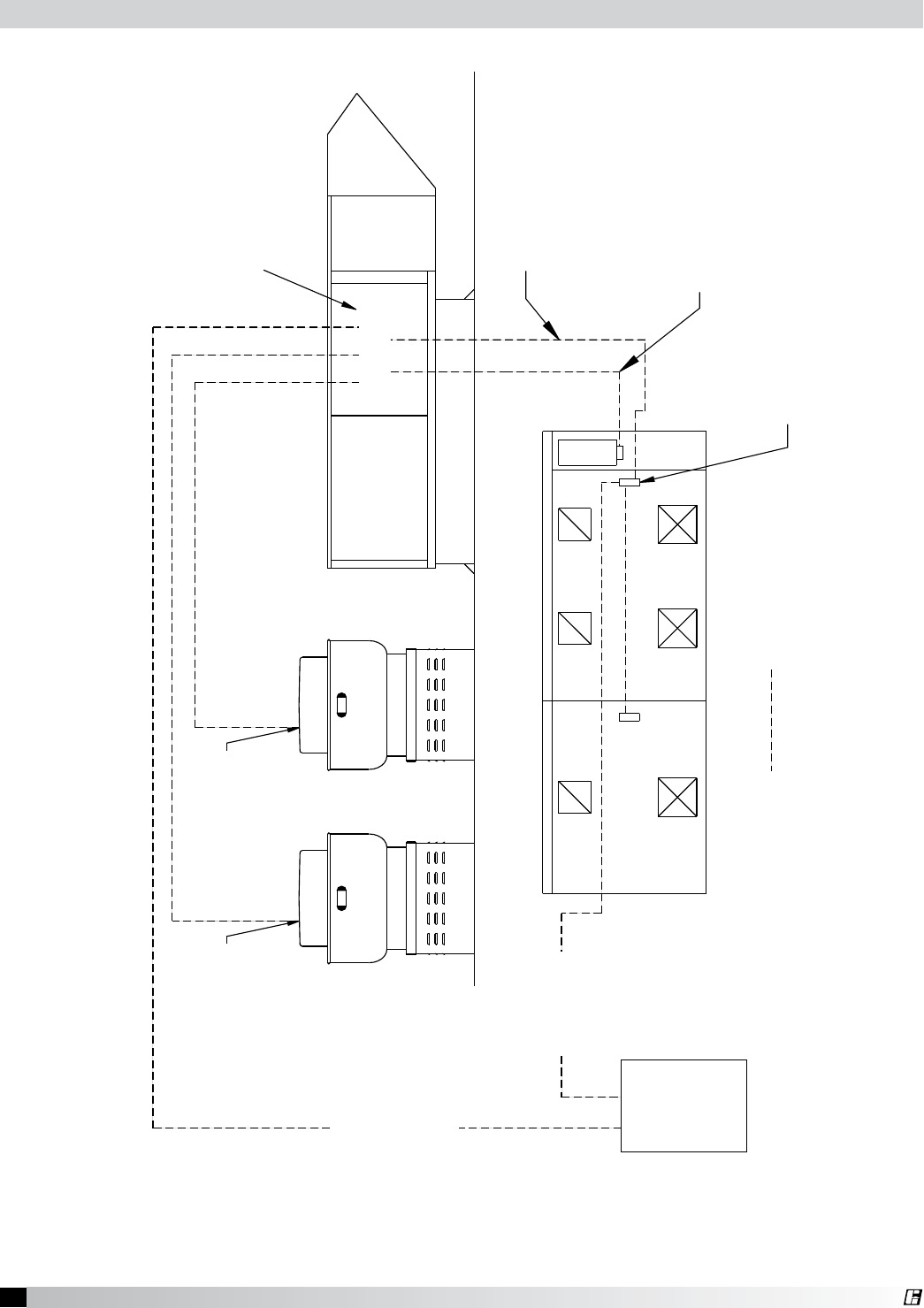
HOOD-1BHOOD-1A
BASIC WIRING DIAGRAM (WIRING BY OTHERS)
FROM MAKE-UP AIR
STARTER #3
TO CUBE FAN
DISCONNECT SWITCH
WIRED THROUGH
BREATHER TUBE ONLY
FROM MAKE-UP AIR
STARTER #2
TO CUBE FAN
DISCONNECT SWITCH
WIRED THROUGH
BREATHER TUBE ONLY
EXHAUST FAN-1A EXHAUST FAN-1B
POWER
PANEL
SUPPLY POWER TO
JUNCTION BOX
ON HOOD FOR HOOD LIGHTS
JUNCTION BOX ON
TOP OF HOOD FOR
FIELD CONNECTION
OF SUPPLY POWER
FIVE (5) CONTROL WIRES
FROM SWITCH JUNCTION
BOX ON HOOD TO MAKE-UP
AIR CONTROL CENTER
CONTROL CENTER
MAKE-UP AIR UNIT
FIELD WIRING
SUPPLY POWER
TO MAKE-UP AIR
CONTROL CENTER
TWO (2) CONTROL WIRES FROM
ANSUL SNAP ACTION SWITCH TO
MOTOR CONTROLS AREA.
ELECTRICAL CONTRACTOR TO
PROVIDE HANDIBOX ON SIDE
OF AUTOMAN.
ANSUL AUTOMAN IS NOT AN
ELECTRICAL RATED BOX.
NO CONNECTIONS INSIDE.
Overall Wiring Plan View
Fig. 48
30 Canopy Hood
®
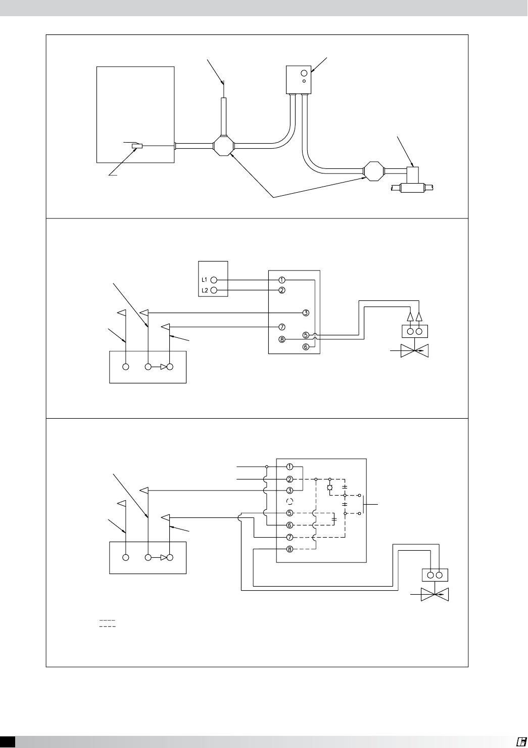
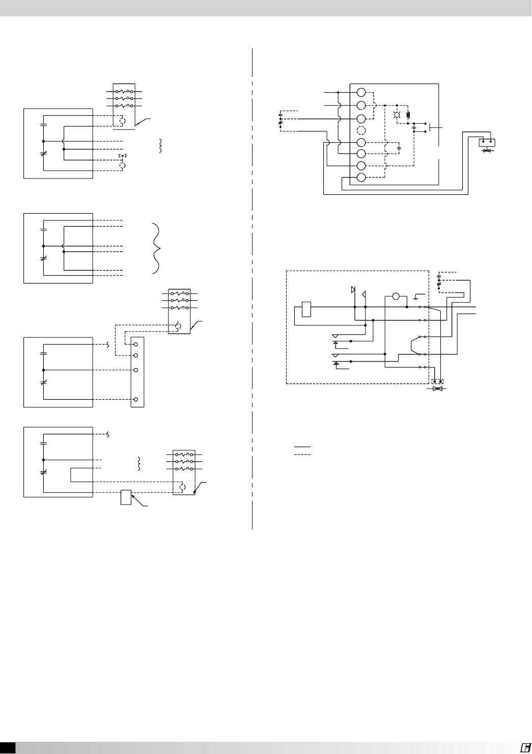
EXHAUST FAN CONTACT
SUPPLY FAN CONTACT
EXHAUST FAN CONTACT
SUPPLY FAN CONTACT
SEPARATE EXHAUST & SUPPLY SWITCHING
COMBINED EXHAUST & SUPPLY SWITCHING
THE SUPPLY FAN WILL BE TURNED OFF IF THE FIRE SYSTEM IS ACTIVATED, AND
ALLOW THE EXHAUST FAN TO CONTINUE TO OPERATE.
CONTROL PANEL TO A FIRE SUPPRESSION CONTACT (FSC1). WHEN WIRED PROPERLY,
THE DIAGRAM BELOW SHOWS HOW TO WIRE THE EXHAUST AND SUPPLY FANS WITH A
SUPPRESSION SYSTEM AND IS NORMALLY MOUNTED IN THE FIRE SYSTEM CONTROL BOX.
THE FIRE SUPPRESSION CONTACT (FSC1) IS PROVIDED AS PART OF THE FIRE
OL OL
ON TOP OF HOOD
LIGHTS
SUPPLY POWER
HOOD
WHITE
JUNCTION BOX
FOR FIELD
CONNECTION OF
120 VOLT
FSC1
CONTROL
VOLTAGE
NH
EXH
FAN
STR CTRLSTR
SUP
FAN HTR
SUP
OL
ON TOP OF HOOD
LIGHTS
HOOD
SUPPLY POWER
JUNCTION BOX
FOR FIELD
CONNECTION OF
120 VOLT
FAN
SUP
STR
CONTROL
115VOLT
NH
STR
FAN
EXH
CTRL
SUP
HTR
SUP FAN
OPTIONAL
OL FSC1
LIGHT
SWITCH
EXHAUST & SUPPLY
SWITCH
HEATER
SWITCH
LIGHT
SWITCH
EXHAUST
SWITCH
SUPPLY
SWITCH
HEATER
SWITCH
HOOD SWITCH
PANEL DETAIL
THE DIAGRAMS BELOW SHOW A TYPICAL HOOD SWITCH PANEL REMOTE MOUNTED.
FOR HOOD MOUNTED SWITCHES REFER TO THE WIRING CONNECTION DECAL ON THE
COVER OF THE JUNCTION BOX ON THE HOOD TOP.
HOOD SWITCH
PANEL DETAIL
CONTROL
VOLTAGE
Wiring for Hood Switch Panels
Fig. 49
The diagrams below show a typical hood switch panel remote mounted. For hood mounted switches
refer to the wiring connection decal on the cover of the junction box on the hood top.
The diagram below shows how to wire the exhaust and supply fans with a control panel to a fire
suppression contact (FSC1). When wired properly, the suppy fan will be turned off if the fire system is
activated and allow the exhaust fan to continue to operate.
The fire suppression contact (FSC1) is provided as part of the fire suppression system and is normally
mounted in the fire system control box.
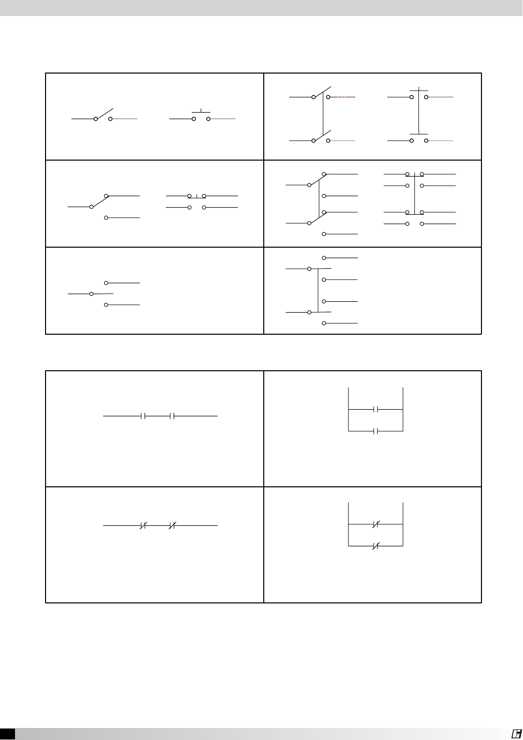
31 Canopy Hood
®
ON
ON (NO)
ON
ON (NO)
ON
ON
ON (NO)
ON
ON (NO)
ON
ON
ON (NO)
ON (NO)
ON ON
ON
ON (NC) ON (NC)
ON
ON (NC)ON (NC)
ON
ON (NC)
ON (NC)
OFF
OFF OFF
OFF
OFF OFF
OFF
OFF OFF
On if both are not activated
Off if both are activated
Off if either are not activated
Off if both are not activated
On if both are activated
Off if either are not activated
Off if both are activated
On if either is activated
On if either is activated
On if both are activated
Off if both are not activated
Off if either not activated
Single Throw
Single Pole Double Pole
Double Throw
Double Throw
Center Off
Series Circuit
Normally Open Contacts
Parallel Circuit
Normally Closed Contacts
Circuit Diagrams
Fig. 50
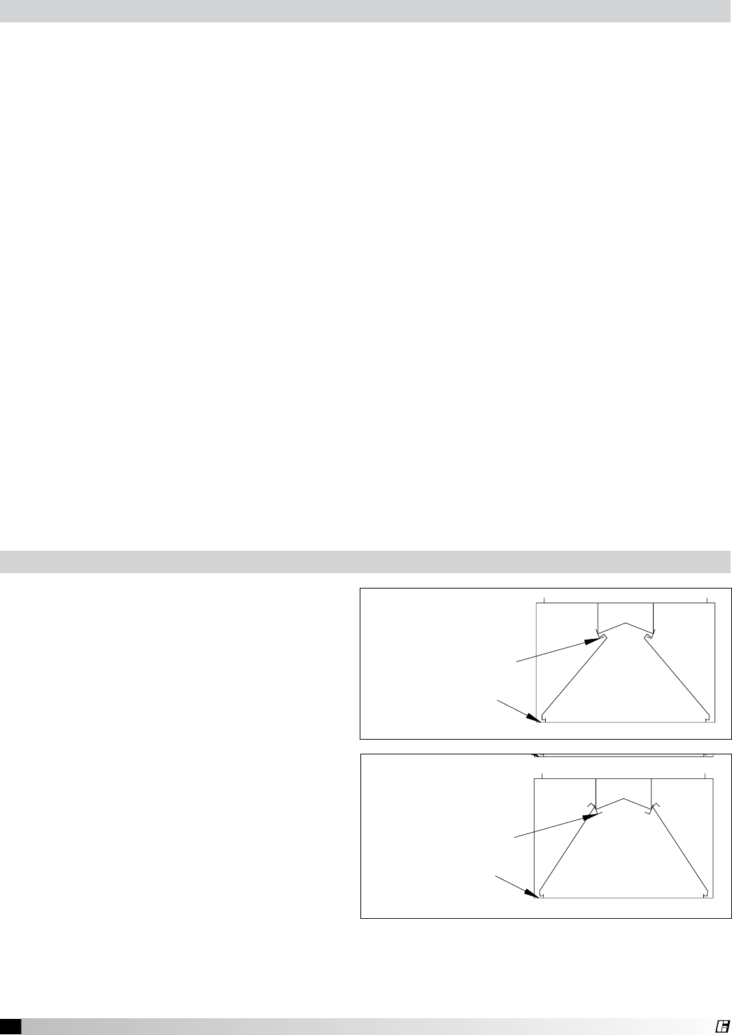
32 Canopy Hood
®
Daily Maintenance
1. Wipe grease from exposed metal surfaces on the hood interior using a clean, dry cloth.
2. Visually inspect the filters or cartridges for grease accumulation.
3. Remove grease cup, empty contents, and replace cup.
Weekly Maintenance
1. Remove the grease filters or cartridges and wash in dishwasher or pot sink.
Note: Filters installed over heavy grease producing equipment may require more frequent
cleaning. See filter cleaning schedule.
2. Before replacing filters, clean the interior plenum surfaces of any residual grease accumulations.
Periodic Maintenance
1. Painted hood exterior surfaces should be cleaned with a mild detergent solution.
2. Stainless steel hood exterior surfaces should be cleaned with a mild detergent and then polished
with a good grade stainless steel polish to preserve the original luster.
Note: Never use abrasive cleaners or chemicals on hood surfaces. Never use chlorine based
cleaners or iron wool pads to clean the hood. They may scratch or mar the material. Always rub
with the grain of the stainless.
3. To maintain optimum performance of your hood and fan, duct cleaning should be performed as
often as the application and code requires.
4. Re-caulk the hoods with an NSF Approved silicone caulk, (GE SCS1009 or its equivalent) as
needed.
1. Grasp the baffle with drain holes facing
down and lift into the hood. For short hoods
with only one baffle it may be necessary to
turn the baffle slightly diagonal to fit it past
the drain channel.
2. After the baffle clears the drain channel of
the hood, turn the baffle so it is lined up with
the upper hanger in the hood.
3. Hook the upper channel of the baffle over
the upper hanger of the hood and set the
lower edge of the baffle into the condensate
gutter. Repeat until all baffles are installed in
the hood.
4. Center the baffle from side to side in the
hood.
Maintenance
Condensate Hood Baffle Installation
UPPER HANGER
UPPER HANGER
CONDENSATE
GUTTER
CONDENSATE
GUTTER
UPPER HANGER
UPPER HANGER
CONDENSATE
GUTTER
CONDENSATE
GUTTER
CORRECT
INCORRECT
Fig. 51
Fig. 52
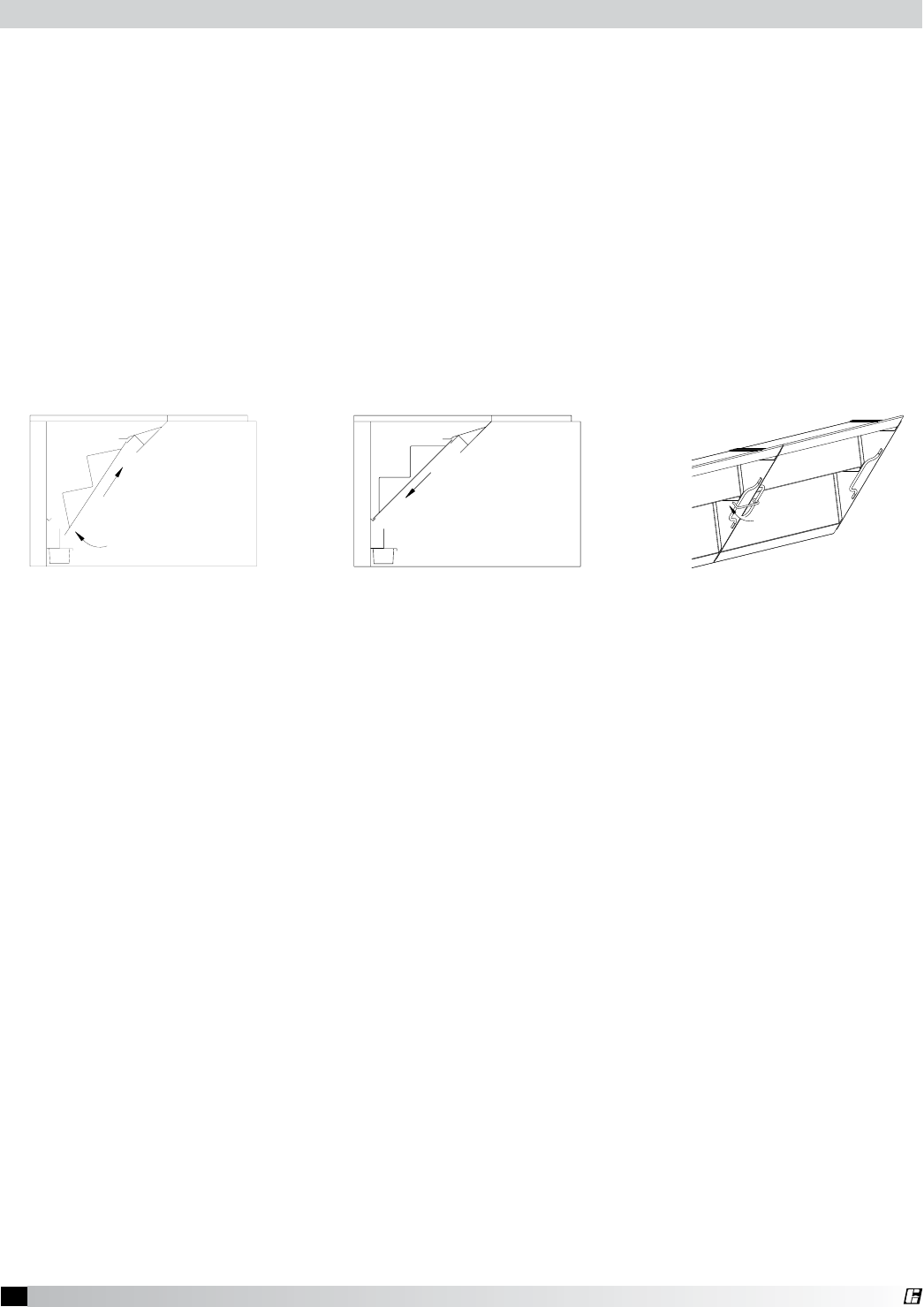
33 Canopy Hood
®
NOTE: Never install the Second Stage filter in the front filter channel. The Second Stage filter
must be installed behind a UL Classified Grease-X-Tractor™ primary filter Model HE or GX.
1. Slide the top edge of the Second Stage filter into the top rear filter channel; Fig. 53.
2. Lifting the lower edge of the filter past the grease trough, continue to push the top of the filter into
the channel.
3. When the filter is even with the bottom rear filter channel, set the filter into the channel; Fig. 54.
4. Slide the filter to one end of the hood and repeat until all the filters are installed. Make sure the
filters are placed tightly together with no visible gaps.
5. Latch filters together by connecting hooks to handle on next filter; Fig. 55.
6. Install the Grease-X-Tractor™ primary filters in the same manner using the front filter channel.
Fig. 55Fig. 54Fig. 53
Grease Grabber™ Filter Installation
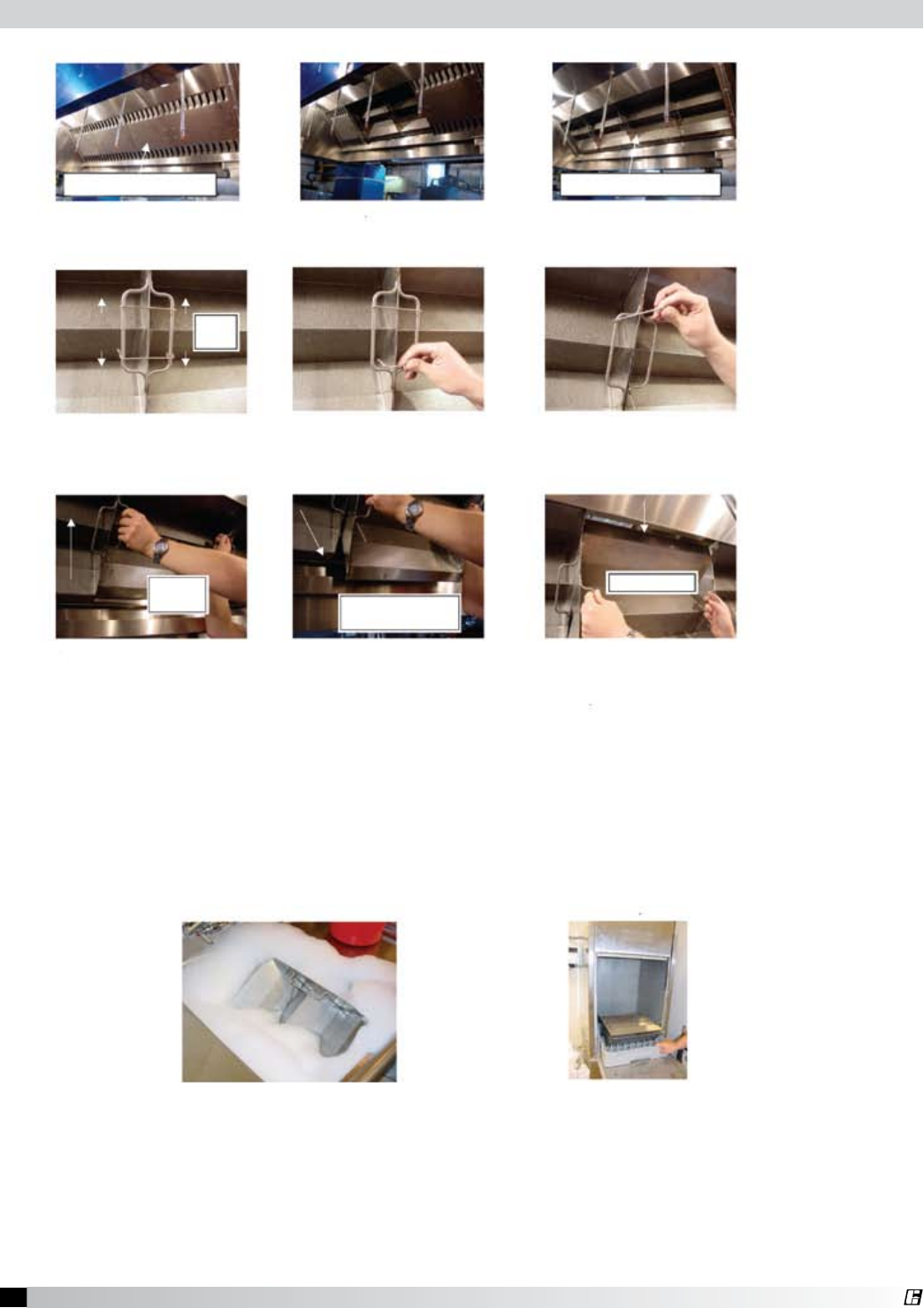
34 Canopy Hood
®
1A 1B
2A 2B
3A 3B
Step 1 Remove the front GX filters: (1A) Remove middle filters first, (1B) slide ends toward middle and remove.
1C
2C
3C
Step 2 Release the hooks that hold the filters together. Slide the top hook upward and the bottom hook downward until the
hook releases. Do this to all filters.
Step 3 Remove the GG filters, starting in the middle of the hood: (3A) Grab the handles on either side and lift the filter up,
(3B) pull the bottom of the filter toward yourself, (3C) lower the filter out of the hood. Repeat this process for each
filter. The filters that are on the ends will have to be slid toward the middle and then lifted out.
Step 4 Frequent Maintenance:
Note: Required washing frequency is dependent on type of cooking and quantity of food cooked.
- Remove filters from hood and place each filter in a whirlpool sink or dishwasher.
- If using a whirlpool sink, cycle for 10 minutes. Use standard dishwash soap. (4A)
- If using a dishwasher, cycle it three times to ensure all grease is removed. (4B)
- If using standard sink, cover with hot water and degreaser and soak for two hours. Rinse after soaking.
Note: For hoods with large quantities of filters, it is acceptable to wash 3 to 4 filters each day, cycling all of the filters in three days.
Note: The beads will discolor. Standard cooking will turn the beads yellow in color. Open flame cooking will cause the beads to
blacken. Neither affects the performance of the filters.
Periodic Inspection:
- Each filter may be soaked in hot soapy water for two hours once a month prior to washing if grease build-up is found.
- Inspect the filters by holding it up to a light. Light shining through more than six holes in a group indicates filter
damage.
- For filter replacement, call 1-800-337-7400
4A 4B
GX Filters, first row of filters GG Filters, second row of filters
Slide
hooks
Slide
filter up Pull bottom of
filter towards yourself
Pull filter down
Step 5 Replace GG filters in hood. Do Step 3 in reverse order. (3C, then 3B, then 3A)
Step 6 Latch filters together by connecting the hooks to the handle on the next filter. Slide hook on from the top and bottom
of the handle. Do not try to snap the hooks into place. Do Step 2 in reverse.
Step 7 Replace the front GX filters. Do Step 1 in reverse. Be sure to install filters in the ends of the hood first, then install the
filters in the middle of the hood (1B, then 1A)
Caution: To prevent damage to filter media, do not wash second stage filters in detergents that contain
hydroxides such as sodium hydroxide or potassium hydroxide.
Grease Grabber™ Filter Cleaning
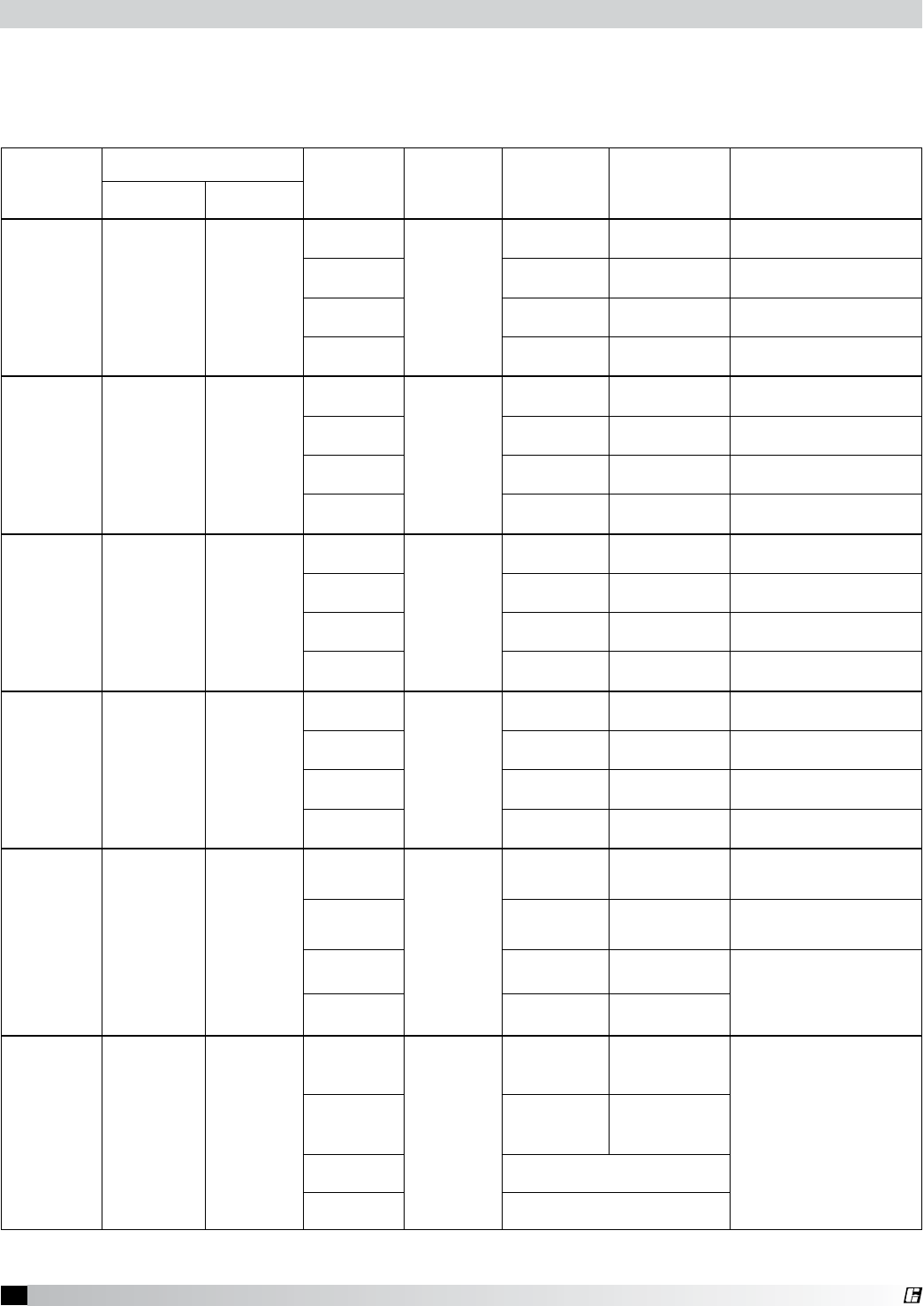
35 Canopy Hood
®
NOTE: Standard cooking will turn the beads yellow in color. Open flame cooking will cause the beads to
blacken. Neither affects the performance of the beads.
Caution: To prevent damage to filter media, do not wash second stage filters in detergents that contain
hydroxides such as sodium hydroxide or potassium hydroxide.
Preference
Washing Equipment Cooking
Equipment Chemical Frequency
Required
Time
or
Cycles
Baffle Filter or
Grease-X-Tractor™
Wash Frequency
Type Temp
1
Best
Commercial
Grade Dish
Washer
180º F
Min
Griddle
Dish
Washer
Detergent
Every 3 days 2 Cycles Every 3 days
2 Cycles
Fryer Weekly 2 Cycles Twice a week
1 Cycle
Charbroiler Daily 2 Cycles Daily
2 Cycles
Wok Daily 2 Cycles Daily
2 Cycles
2
Low Temp.
Dish Washer
(Chemical
Sanitizer)
140º F
Griddle
Dish
Washer
Detergent
Every 3 days 3 Cycles Every 3 days
2 Cycles
Fryer Weekly 3 Cycles Twice a week
2 Cycles
Charbroiler Daily 4 Cycles Daily
2 Cycles
Wok Daily 4 Cycles Daily
2 Cycles
3
Power
Wash Sink
(Whirlpool)
with Heater
180º F
Min
Griddle
Pot & Pan
Detergent
Every 3 days 10 Minutes Every 3 days
5 minutes
Fryer Weekly 10 Minutes Twice a week
5 minutes
Charbroiler Daily 15 Minutes Daily
5 minutes
Wok Daily 15 Minutes Daily
5 minutes
4
Power
Wash Sink
(Whirlpool)
no Heater
140º F
Griddle
Pot & Pan
Detergent
Every 3 days 15 Minutes Daily
5 minutes
Fryer Weekly 15 Minutes Twice a week
5 minutes
Charbroiler Daily 25 Minutes Daily
10 minutes
Wok Daily 25 Minutes Daily
10 minutes
5
Pot Sink
with Heater
(rinse with
sprayer after
soaking)
180º F
Griddle
Pot & Pan
Detergent
and/or
Degreaser
Every 2 days 1 Hour
Daily
Soak 10 min., then scrub with
scour pad and bottle brush
Fryer Every 2 days 1 Hour
Daily
Soak 5 min., then scrub with
scour pad and bottle brush
Charbroiler Daily 2 Hours Daily
Soak 10 min., then scrub with
scour pad and bottle brush
Wok Daily 2 Hours
6
Worst
Pot Sink
no Heater
(rinse with
sprayer after
soaking)
140º F
Griddle
Commercial
Grade
Kitchen
Degreaser
Daily
2 Hours
Change hot water
every 30 minutes
Daily
Soak 10 minutes then scrub
with scour pad & bottle brush
Fryer Every 2 days
2 Hours
Change hot water
every 30 minutes
Charbroiler Not Recommended
Wok Not Recommended
Filter Washing Frequency Guide

36 Canopy Hood
®
Troubleshooting
Problem: Exhaust fan is not operating or is not operating at design levels.
Is the fan receiving power? Replace fuses, reset circuit breakers, check disconnect.
Is the belt loose or broken? Replace or tighten belt.
Is the fan rotating in correct direction? Have the electrician correctly wire the fan.
Is the make-up air operating? Problems with make-up air may interfere with the exhaust fan -
check the manufacturers installation manual.
Does the airflow need to be increased? Adjust or replace pulleys to increase fan RPM, install a larger motor.
Does the fan vibrate?
Clean the fan wheel/blade, replace fan wheel if damaged, check for
loose bolts, check for broken or damaged components, check for
rags and other foreign objects.
Problem: Hood is full of smoke. There is smoke coming out of the edges of the hood.
Is the fan operating at design levels? See exhaust fan troubleshooting section.
Is the fan correctly sized?
Refer to test and balance report, design specifications and fan
curves; have an electrician check the motor amperage; try removing
the filter temporarily to see if capture improves. (Make sure to
replace filter to prevent risk of fire!); switch to different filters with
lower static pressure.
Are the filters in good condition? Clean filters, replace damaged filters, properly position filters.
Is there sufficient make-up air?
(Kitchen should be in a slight negative
but not excessive. Check to see if there
is a strong draft through an open door).
Check make-up air unit, increase make-up air, make-up air should be
evenly distributed throughout the kitchen.
Does the current cooking equipment
match the original design? Adjust or replace fan to match the cooking equipment load.
Are there multiple hoods on one fan? One hood may be over exhausting and the other hood not drawing
enough. Restrict second hood to help problem hood.
Are there closed dampers in the duct? Open dampers.
Is the ductwork complex or to small? Change to a higher static fan, modify the ductwork.
Is the ductwork obstructed? Clear obstruction.
Is this a short circuit hood? Turn off or reduce the amount of air supplied to short circuit.
Problem: Smoke blows away before reaching the bottom of the hood.
Are there cooling fans directed at the
hood or cooking equipment? Turn off or redirect fans.
Are there ceiling diffusers directing air at
the hood?
Move diffusers to more neutral area or replace with a diffuser that
directs air away from the hood.
Are there open windows or doors? Close windows and doors.
Are there cross drafts or other drafts in
the kitchen?
Find source of the draft and eliminate, add side skirts to hood (test
with cardboard – use stainless for permanent side skirts); increase
the amount of overhang on the spillage side; add a 6 in. lip around
the base of the hood (test with cardboard – use stainless for
permanent side skirts); make-up air should be spread out evenly
through the kitchen.
Is the hood near a main walkway? Add side skirts to hood (test with cardboard first); increase the
amount of overhang on spillage side.

37 Canopy Hood
®
Troubleshooting
Problem: Smoke blows away before reaching the bottom of the hood.
Are there pass-thru windows near
the hood?
Adjust amount and locations of make-up air to eliminate drafts
through the pass-thru windows.
Is this an air curtain hood? Turn off or reduce the amount of make-up air.
Is the make-up air part of the hood
or an attached plenum?
Try turning off or reducing the amount of make-up air; block off
portions of the supply to direct air away from the problem area (test
with cardboard).
Problem: Pilot lights are being blown out or cooking equipment is being cooled by make-up air.
Are there drafts from make-up air?
Try turning off or reducing the amount of make-up air; block off
portions of the supply to direct air away from the problem area (test
with cardboard first); remove any obstructions in front of supply that
directs air toward cooking equipment.
Problem: Cold air can be felt by the cook at the hood.
Is this a short circuit hood? Turn off or reduce the amount of air supplied to short circuit.
Is this an air curtain hood? Turn off or reduce the amount of air supplied to the air curtain; heat
the supply air.
Is the make-up air part of the hood
or an attached plenum?
Try turning off or reducing the amount of make-up air; heat the
supply air.
Problem: The kitchen gets hot.
Is the hood capturing? Hood is not drawing enough air, see sections above on fan
performance and hood capture.
Is this an air curtain hood? Turn off or reduce the amount of air supplied to the air curtain.
Is the make-up air part of the hood
or an attached plenum?
Try turning off or reducing the amount of make-up air; cool the
supply air.
Problem: Cooking odors in the dining area.
Is the hood capturing? Hood is not drawing enough air, see sections above on fan
performance and hood capture.
Is there a draft through doors between
the kitchen and dining area?
Decrease make-up air in the kitchen; increase exhaust air through
hood.
Problem: Grease is running off the hood.
Is there grease on top of the hood? Exhaust duct is not correctly welded.
Is the caulk missing or damaged? Clean problem area and re-caulk.
Is the grease cup inserted properly? Put grease cup back in place.
Problem: Hood is noisy.
Is the fan running in the correct direction? See exhaust fan troubleshooting section.
Are the filters in place? Replace missing filters.
Is the hood over exhausting? Slow down fan (see exhaust fan troubleshooting section)

38 Canopy Hood
®
Before calling your manufacturers representative to report a problem have the
following information available:
1. Review / summary of troubleshooting section in installation operation manual.
2. Hood model and serial number.
3. Current cooking equipment line-up.
4. Size of hood (length, width and height).
5. Island or wall configuration.
6. Multiple hoods on one fan.
7. Nature of spillage (one end; all around the edges).
8. Does the smoke make it to the hood?
9. Height hood is mounted above finished floor.
10. How make-up air is brought into the kitchen (hood, ceiling diffusers, separate plenum).
11. Is exhaust system controlled by a variable volume system?
12. Is the fan noisy?
GREENHECK
PART NUMBER
FILTER DESCRIPTION
(HEIGHT X WIDTH X DEPTH)
457626 16 x 16 x 2 Aluminum Baffle Filter
457628 16 x 20 x 2 Aluminum Baffle Filter
457632 20 x 16 x 2 Aluminum Baffle Filter
457634 20 x 20 x 2 Aluminum Baffle Filter
457627 16 x 16 x 2 Stainless Steel Baffle Filter
457629 16 x 20 x 2 Stainless Steel Baffle Filter
457633 20 x 16 x 2 Stainless Steel Baffle Filter
457635 20 x 20 x 2 Stainless Steel Baffle Filter
851656 16 x 16 High Velocity Cartridge Filter
851657 16 x 20 High Velocity Cartridge Filter
851659 20 x 16 High Velocity Cartridge Filter
851660 20 x 20 High Velocity Cartridge Filter
851703 16 x 16 Grease-X-Tractor™ Aluminum Filter
851704 16 x 20 Grease-X-Tractor™ Aluminum Filter
851706 20 x 16 Grease-X-Tractor™ Aluminum Filter
851707 20 x 20 Grease-X-Tractor™ Aluminum Filter
851709 16 x 16 Grease-X-Tractor™ SS Filter
851710 16 x 20 Grease-X-Tractor™ SS Filter
851712 20 x 16 Grease-X-Tractor™ SS Filter
851713 20 x 20 Grease-X-Tractor™ SS Filter
458763 16 x 16 Flame Gard® 1 Baffle Filter
458764 16 x 20 Flame Gard® 1 Baffle Filter
454878 20 x 16 Flame Gard® 1 Baffle Filter
454879 20 x 20 Flame Gard® 1 Baffle Filter
852208 20 x 16 Grease Grabber™ Second Stage Filter
852207 20 x 20 Grease Grabber™ Second Stage Filter
852388 16 x 16 Grease Grabber™ Second Stage Filter
852389 16 x 20 Grease Grabber™ Second Stage Filter
Replacement Parts
39 Canopy Hood
®
GREENHECK
PART NUMBER REGISTERS
452700 24 x 8 Aluminum Single Deflection H-OB
452701 36 x 8 Aluminum Single Deflection H-OB
452702 36 x 8 Aluminum Single Deflection H-OB
452703 44 x 8 Aluminum Single Deflection H-OB
453796 24 x 12 Aluminum Single Deflection H-OB
453797 36 x 12 Aluminum Single Deflection H-OB
453798 38 x 12 Aluminum Single Deflection H-OB
453799 44 x 12 Aluminum Single Deflection H-OB
452729 24 x 8 Aluminum 38° Fixed Blade RA-OB
452730 30 x 8 Aluminum 38° Fixed Blade RA-OB
452731 36 x 8 Aluminum 38° Fixed Blade RA-OB
452732 38 x 8 Aluminum 38° Fixed Blade RA-OB
452733 44 x 8 Aluminum 38° Fixed Blade RA-OB
GREENHECK
PART NUMBER SWITCHES
850551 Light Switch Only
851776 Fan Switch Only
851777 Light Switch & Fan Switch ( 2 switches)
851778 Fan Switch & Heat Switch (2 switches)
851779 Exhaust, Fan & Supply Switch (2 switches)
851780 Light, Fan & Heat Switch (3 switches)
851781 Light, Exhaust, Supply Separate Switch (3 switches)
851782 Exhaust, Supply, Heat Separate Switch (3 switches)
851783 Light, Exhaust, Supply, Heat Separate Switch (4 switches)
851784 Fan Switch & Temper (3 position) (2 switches)
851510 Light, Fans, & Temper (3 position) (3 switches)
851511 Exhaust, Supply, & Temper (3 position) (3 switches)
851512 Light, Exhaust, Supply, & Temper (3 position) (4 switches)
851618 Automatic Fire Damper Test Switch
GREENHECK
PART NUMBER MISCELLANEOUS
451131 Grease Cup
453498 Glass Globes for hood lights (clear)
851744 Grease Extractor Filter Removal Tool
851834 Baffle Filter Removal Tool
851747 High Velocity Cartridge Filter Removal Tool
Replacement Parts

40 452413 • Canopy Hood, Rev. 7, March 2008 Copyright 2008 © Greenheck Fan Corp.
Greenheck warrants this equipment to be free from defects in material and workmanship for a period of one year from
the shipment date. Any units or parts which prove defective during the warranty period will be replaced at our option
when returned to our factory, transportation prepaid. Motors are warranted by the motor manufacturer for a period of
one year. Should motors furnished by Greenheck prove defective during this period, they should be returned to the
nearest authorized motor service station. Greenheck will not be responsible for any removal or installation costs.
As a result of our commitment to continuous improvement, Greenheck reserves the right to change specifications
without notice.
®
Contact Greenheck Fan Corporation:
Phone:(715)359-6171•Fax:(715)355-2399•E-mail:gfcinfo@greenheck.com•Website: www.greenheck.com
Warranty
