Greenheck Fan Combination Fire Smoke Dampers Fsd M211 Users Manual
FSD-M211 to the manual 74d69a7b-5312-4e35-b469-aeb72681996b
2015-02-09
: Greenheck-Fan Greenheck-Fan-Combination-Fire-Smoke-Dampers-Fsd-M211-Users-Manual-562482 greenheck-fan-combination-fire-smoke-dampers-fsd-m211-users-manual-562482 greenheck-fan pdf
Open the PDF directly: View PDF ![]() .
.
Page Count: 6
Model FSD-M211 meets the requirements for fire
dampers, smoke dampers and combination fire
smoke dampers established by:
National Fire Protection Association
NFPA Standards 80, 90A, 92A, 92B, 101, & 105
IBC International Building Codes
ICBO Uniform Building Codes
SBCCI Standard Building Codes
British Standard BS476
Tested to 4 hours at Warrington Fire, UK
Application
Model FSD-M211 is a combination fire smoke damper with 3V style
blades. The FSD-M211 has been qualified to 10.2 m/s and 1 kPa for
operation and dynamic closure in emergency fire smoke situations.
Model FSD-M211 may be installed vertically (with blades running
horizontal) or horizontally and is rated for airflow and leakage in
either direction.
Model FSD-M211 has also been tested in accordance with BS476 to
4 hours at Warrington Fire, UK, and is approved for fire partitions of
4 hours or less where British Standards are required.
Ratings
UL 555 Fire Resistance Rating
Fire Rating: 1
1⁄2 Hours
Dynamic Closure Rating: Actual ratings are size dependant
Maximum Velocity: 10.2 m/s
Maximum Pressure: 1 kPa
UL 555S Leakage Rating
Leakage Class: I
Operational Rating: Actual ratings are actuator dependant
Maximum Velocity: 10.2 m/s
Maximum Pressure: 1 kPa
Max. Temperature: 177°C —Depending on actuator
BS476 Fire Resistance Rating
Fire Rating: 4 hours
Standard Construction
Frame: 127mm x 25mm galv. steel hat
channel with reinforced corners . A
low profile head and sill are used on
sizes less than 432mm high to
maximize free area and
performance.
Blades: 1.5mm galvanized steel, reinforced
with 3 longitudinal structurally
designed vee’s.
Seals: Extruded silicone rubber blade
seals. Flexible stainless steel jamb
seals.
Closure Device: 74°C RRL
Linkage: Concealed in jamb.
Axles: 13mm diameter plated steel
Bearings: Bronze sleeve type.
Size Limitations
Minimum Size: 101mm W x 101mm H
Maximum Size:
Single Section: 813mm W x 1270mm H
or 914mm W x 914mm H
Multiple Section: 3251mm W x 2540mm H Vertical
or 3658mm W x 2438mm H
Horizontal
Optional Features
• Stainless steel bearings
• 100°C, and 177°C RRL available (UL only)
• 69°C fusible link (BS476)
• Electric or pneumatic actuators to accomplish smoke
management and system functions.
• Sleeve with Integral flange on both sides available
• RRL/OCI (open close indication)
• TOR (remote override of 74°C or 100°C closure allows damper to
perform smoke management functions during a fire emergency)
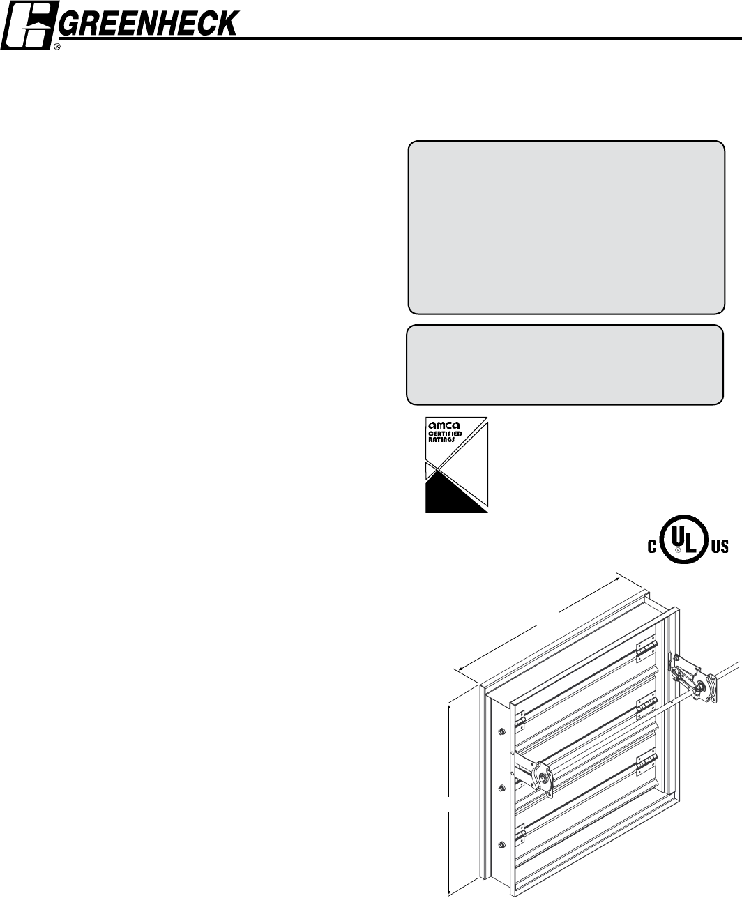
Model FSD-M211
Steel 3V Blades
UL 555S Leakage Class I
UL555 11⁄2 Hour Fire Resistance Rating
4 Hour Fire Resistance Rating (BS476)
Combination FIRE SMOKE DAMPERS
* W & H dimensions furnished approximately 6mm undersize.
(Add sleeve thickness for overall sleeved damper dimension)
Right hand drive is shown. Left hand drive is available upon request.
H
W
LH
RH
“UL CLASSIFIED (see complete marking on
product)”
“UL CLASSIFIED to Canadian safety standards
(see complete marking on product)”
Standard 555 & 555S (Listing #R13317)
Greenheck Kunshan Co. Ltd. and Greenheck Fan
Corporation certifies that the model FSD-M211
shown herein is licensed to bear the AMCA Seal. The
ratings shown are based on tests and procedures
performed in accordance with AMCA Publication
511 and comply with the requirements of the AMCA
Certified Ratings Programs. The AMCA Certified
Ratings Seal applies to air performance ratings only.
®
AIR
MOVEMENT
AND CONTROL
ASSOCIATION
INTERNATIONAL, INC.
AIR
PERFORMANCE
Installation instructions available at www.greenheck.com
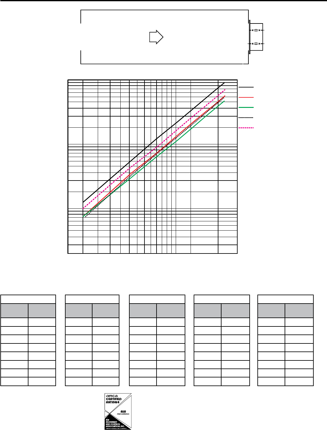
Pressure Drop Data FSD-M211
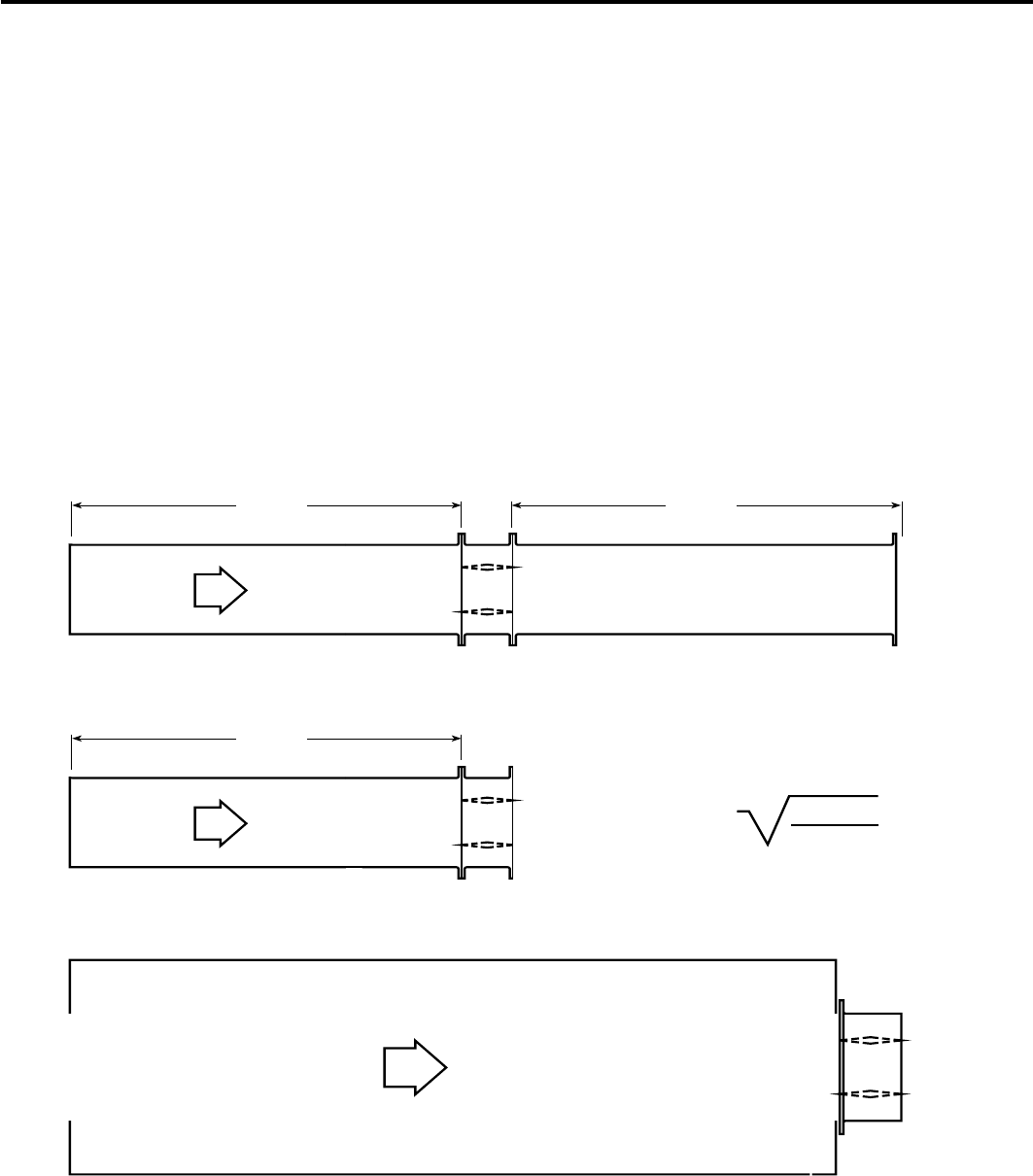
This pressure drop testing was conducted in accordance with AMCA Standard 500-D using the three configurations shown. All
data has been corrected to represent standard air at a density of 1.201 kg/m3.
Actual pressure drop found in any HVAC system is a combination of many factors. This pressure drop information along with an
analysis of other system influences should be used to estimate actual pressure losses for a damper installed in a given HVAC
system.
AMCA Test Figures
Figure 5.3 Illustrates a fully ducted damper. This configuration has the lowest pressure drop of the three test configurations
because entrance and exit losses are minimized by straight duct runs upstream and downstream of the damper.
Figure 5.2 Illustrates a ducted damper exhausting air into an open area. This configuration has a lower pressure drop than
Figure 5.5 because entrance losses are minimized by a straight duct run upstream of the damper.
Figure 5.5 Illustrates a plenum mounted damper. This configuration has the highest pressure drop because of extremely high
entrance and exit losses due to the sudden changes of area in the system.
5D 6D
5D
D4 (W) (H)
3.14
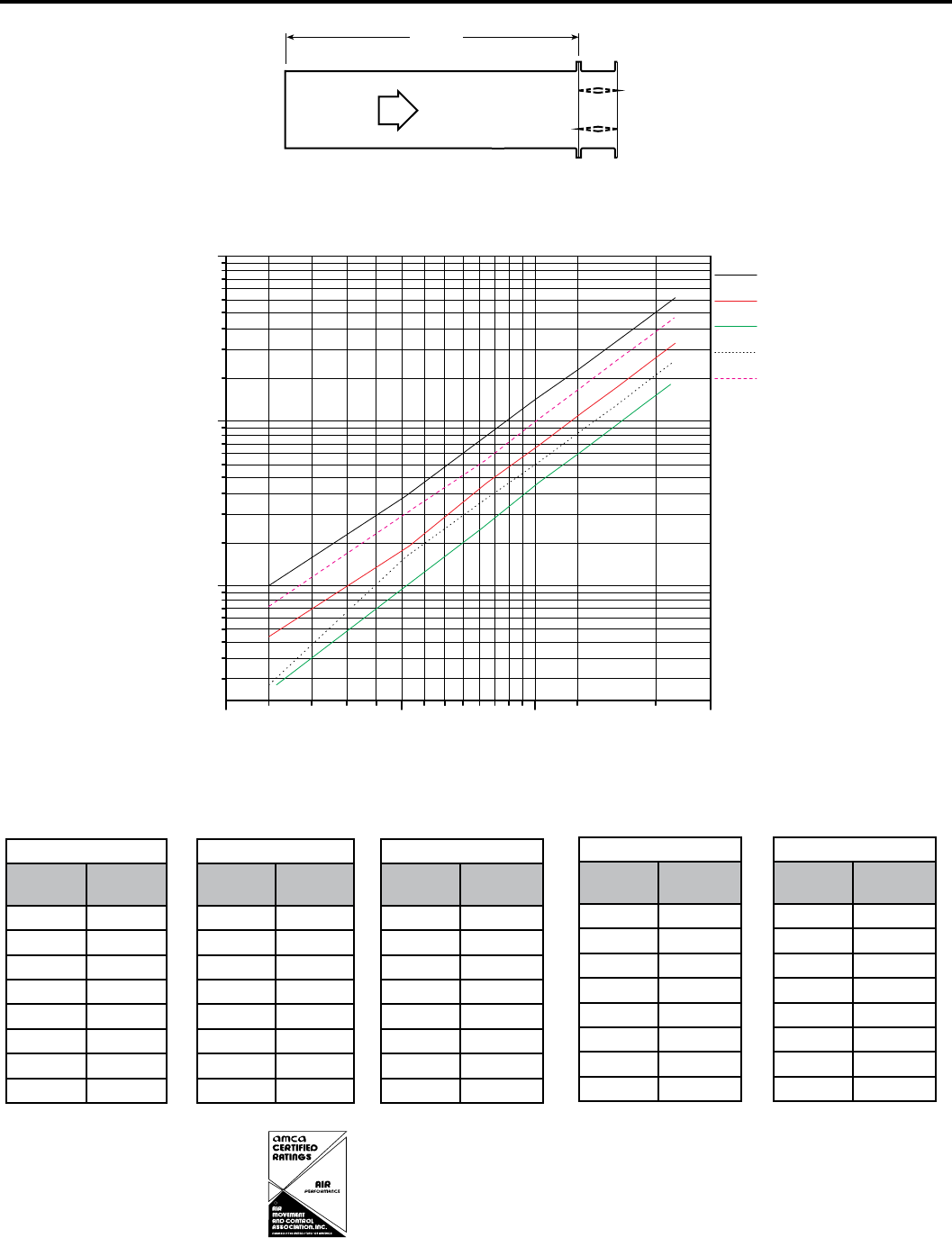
AMCA 5.2 Pressure Drop FSD-M211
5D 6D
5D
D=4 (W) (H)
3.14
Figure 5.3
Figure 5.2
Figure 5.5
NNYNN
NNYNN
NNYNN
NNYNN
NNYNN
13&4463&%3011"4$"-4
'"$&7&-0$*5:.&5&344&$0/%
".$"
7&-0$*5:7413&4463&%301
Y
Y
Y
Y
Y
305mm x 305mm
Velocity
(m/s)
Pressure
Drop (Pa)
2.5 10
5.1 35
7.7 80
10 135
12.6 207
15.5 311
17.8 411
20.8 561
610mm x 610mm
Velocity
(m/s)
Pressure
Drop (Pa)
2.5 5
5.2 17
7.8 42
10.3 72
12.9 115
15.4 162
18.1 224
20.8 296
914mm x 914mm
Velocity
(m/s)
Pressure
Drop (Pa)
2.6 3
5.1 10
7.6 22
10.2 42
12.7 65
15.3 95
17.7 127
20.3 167
305mm x 1219mm
Velocity
(m/s)
Pressure
Drop (Pa)
2.5 3
5.1 15
7.6 32
10.3 57
12.9 90
15.3 125
18 174
20.5 227
1219mm x 305mm
Velocity
(m/s)
Pressure
Drop (Pa)
2.5 8
5.1 27
7.7 57
10.3 105
12.9 164
15.6 242
17.9 316
20.7 424
R
Greenheck Kunshan Co. Ltd. and Greenheck Fan
Corporation certifies that the model FSD-M211 shown
herein is licensed to bear the AMCA Seal. The ratings
shown are based on tests and procedures performed
in accordance with AMCA Publication 511 and comply
with the requirements of the AMCA Certified Ratings
Programs. The AMCA Certified Ratings Seal applies to
air performance ratings only.
305mm x 305mm
Velocity
(m/s)
Pressure
Drop (Pa)
2.4 5
5.1 22
7.8 52
10.3 92
12.9 145
15.4 209
17.7 274
20.8 379
610mm x 610mm
Velocity
(m/s)
Pressure
Drop (Pa)
2.5 3
5 10
7.7 22
10.3 40
12.8 62
15.5 92
17.9 122
20.8 167
914mm x 914mm
Velocity
(m/s)
Pressure
Drop (Pa)
2.5 3
5.1 8
7.6 15
10.1 27
12.8 42
15.3 62
17.7 82
20.3 107
305mm x 1219mm
Velocity
(m/s)
Pressure
Drop (Pa)
2.5 3
5.1 10
7.7 25
10.3 42
12.9 67
15.7 100
18.7 140
20.9 174
1219mm x 305mm
Velocity
(m/s)
Pressure
Drop (Pa)
2.5 5
5.1 20
7.6 40
10.1 72
12.7 112
15.3 164
18 227
20.6 299
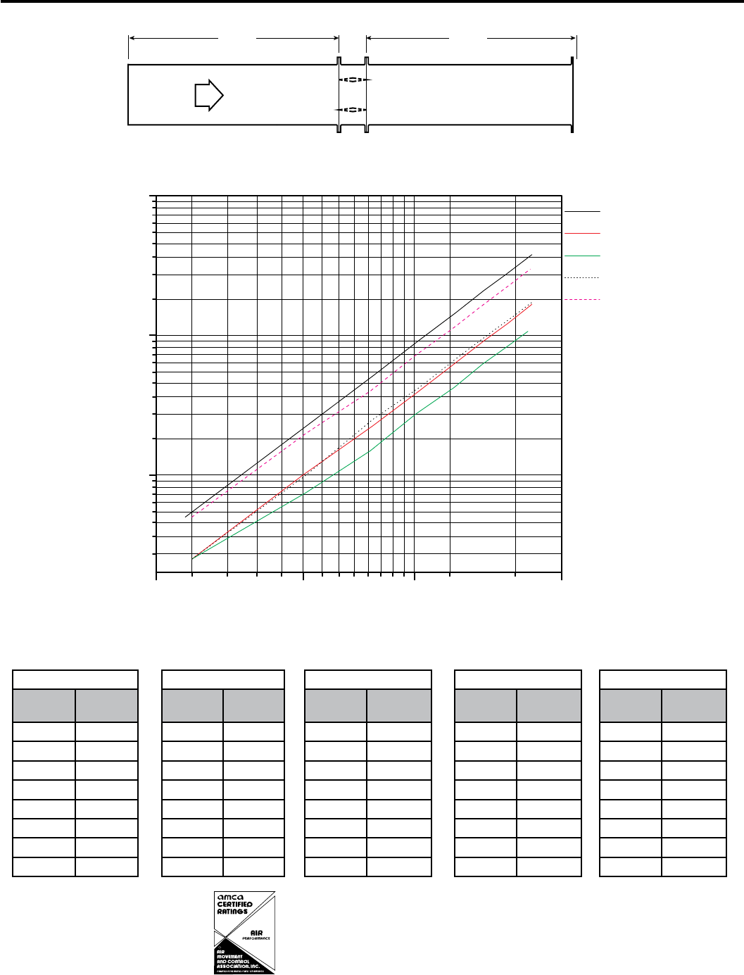
AMCA 5.3 Pressure Drop FSD-M211
5D 6D
5D
D=4 (W) (H)
3.14
Figure 5.3
Figure 5.2
Figure 5.5
NNYNN
NNYNN
NNYNN
NNYNN
NNYNN
13&4463&%3011"4$"-4
'"$&7&-0$*5:.&5&344&$0/%
".$"
7&-0$*5:7413&4463&%301
Y
Y
Y
Y
Y
R
Greenheck Kunshan Co. Ltd. and Greenheck Fan
Corporation certifies that the model FSD-M211 shown
herein is licensed to bear the AMCA Seal. The ratings
shown are based on tests and procedures performed
in accordance with AMCA Publication 511 and comply
with the requirements of the AMCA Certified Ratings
Programs. The AMCA Certified Ratings Seal applies to
air performance ratings only.
305mm x 305mm
Velocity
(m/s)
Pressure
Drop (Pa)
2.5 13
5 55
7.5 122
10.2 222
12.7 349
15.4 508
17.9 688
20.6 907
610mm x 610mm
Velocity
(m/s)
Pressure
Drop (Pa)
2.5 8
5 35
7.6 75
10.3 140
12.8 217
15.3 309
17.7 409
20.8 568
914mm x 914mm
Velocity
(m/s)
Pressure
Drop (Pa)
2.5 8
5.1 30
7.7 67
10.2 115
12.9 184
15.5 269
18.1 354
20.6 471
305mm x 1219mm
Velocity
(m/s)
Pressure
Drop (Pa)
2.6 8
5.1 32
7.7 75
10.2 130
12.7 202
15.5 301
18.1 416
20.6 536
1219mm x 305mm
Velocity
(m/s)
Pressure
Drop (Pa)
2.5 1
5 42
7.7 95
10.3 172
12.7 264
15.3 381
17.9 521
20.8 707
AMCA 5.5 Pressure Drop FSD-M211
5D 6D
5D
D4 (W) (H)
3.14
2 5 10 30
10
100
1000
305mm x 305mm
610mm x 610mm
914mm x 914mm
305mm x 1219mm
1219mm x 305mm
PRESSURE DROP- PASCALS
FACE VELOCITY- METERS/SECOND
AMCA 5.5
VELOCITY VS. PRESSURE DROP
305 x 305
1219 x 305
610 x 610
305 x 1219
914 x 914
R
Greenheck Kunshan Co. Ltd. and Greenheck
Fan Corporation certifies that the model FSD-
M211 shown herein is licensed to bear the AMCA
Seal. The ratings shown are based on tests and
procedures performed in accordance with AMCA
Publication 511 and comply with the requirements
of the AMCA Certified Ratings Programs. The AMCA
Certified Ratings Seal applies to air performance
ratings only.
GREENHECK
Greenheck Kunshan Co Ltd.
17 Qunyi Minying District • Kunshan Economic &
Technical Development Zone
Kunshan, Jiangsu, China 215300
Tel: 0512-573-66666 • Fax: 0512-573-78633
www.greenheck.com
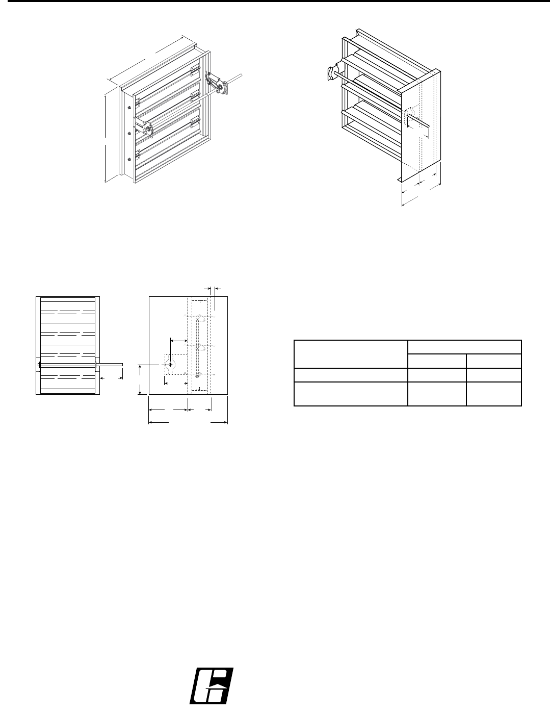
Damper Sleeve Dimensional Data
The drawings below and corresponding table show the position of the FSD-M211 damper when mounted in a factory sleeve.
The standard mounting locations provide enough space for the mounting of actuators, controls and allow space for installation
of retaining angles and duct connections.
127mm
Right hand drive is shown
Left hand drive available upon request
LH RH
A
Sleeve Length
Varies
B*
S
T*
152mm
38mm max.
95mm
137mm
The "A" dimension is the location of the damper mounted
in a factory sleeve. The table below shows the Standard,
Minimum, and Maximum “A” dimensions.
Specifications
Combination Fire Smoke Dampers meeting the following specifications shall
be furnished and installed where shown on plans and/or as described in
schedules. Dampers shall meet the requirements of the latest edition of NFPA
80, 90A, 92A, 92B, 101, and 105.
Dampers shall be tested, rated and labeled in accordance with the latest
edition of UL Standards 555 and 555S. Dampers shall have a UL 555 fire rating
of 11⁄2 hours. Each damper shall be equipped with a heat responsive device
which has been tested and approved for use with the damper assembly in
accordance with UL 555. The heat responsive device shall have a temperature
rating of (specifier select one of the following) 74°C, 100°C, or 177°C. Dampers
shall be UL labeled for use in dynamic systems. The damper shall have a
dynamic closure airflow rating equal to or greater than the airflow at the
damper’s installed location and a dynamic closure pressure rating of 1 kPa.
Dampers shall have a UL 555S Leakage rating of Class I and a Temperature
rating of 177°C. Dampers shall have a UL 555S operational airflow rating equal
to or greater than the airflow at its installed location and an operational pressure
rating of 996 Pa. Damper actuators shall be factory mounted and qualified for
use with the damper in accordance with UL 555S. Damper actuators shall
be (specifier select one of the following) electric type for 120 (24 or 230) volt
operation or pneumatic type for 25 psi minimum (30 psi maximum) operation.
Manufacturers submittal data shall indicate actuator space requirements
around the damper.
All UL 555 and 555S Dynamic Closure Ratings, Operational Ratings and
Leakage Ratings shall be qualified for airflow and pressure in either direction
through the damper. UL ratings shall allow for mounting damper vertically (with
blades running horizontal) or horizontally.
The Damper Manufacturers submittal data shall certify all air performance
pressure drop data is licensed in accordance with the AMCA Certified Ratings
Program for Test Figures 5.2, 5.3 and 5.5. Damper air performance data shall
be developed in accordance with the latest edition of AMCA Standard 500-D.
Dampers shall be labeled with the AMCA Air Performance Seal.
Damper blades shall be 1.5mm galvanized steel 3V type with three longitudinal
grooves for reinforcement. Blades shall be completely symmetrical relative to
their axle pivot point, presenting identical resistance to airflow and operation in
either direction through the damper (blades that are non-symmetrical relative to
their axle pivot point or utilize blade stops larger than 13mm are unacceptable).
Damper frames shall be galvanized steel formed into a structural hat channel
shape with reinforced corners. Bearings shall be sintered bronze sleeve type
rotating in extruded holes in the damper frame. Jamb seals shall be stainless
steel compression type.
Basis of design is Greenheck Model FSD-M211.
Copyright © 2008 Greenheck Fan Corporation
FSD-M211 Rev. 6 January 2008
The following figures show maximum damper section size.
H
W
Single Section
A
127mm.
305mm
*
152mm .
127mm
A
Sleeve Length
Varies
38mm max
95mm
137mm
Damper Sizing Information
*With the exception of dampers 10 in. high (254mm) or less.
NOTE: Entire damper frame is not required to be installed within the
wall. The damper blades, when closed should be contained within
the wall.
in. (mm) "A" Dimension
Standard Maximum
All Dampers* 7 3/16 (183) 12 (305)
When H is 11 in. (279mm) or
less with OCI, RRL, or TOR
12 (305) 12 (305)
