Grizzly G0602 User Manual To The A1b628d1 Ddae 452d B983 Eed175bae992
User Manual: Grizzly G0602 to the manual
Open the PDF directly: View PDF ![]() .
.
Page Count: 96

COPYRIGHT © MARCH, 2013 BY GRIZZLY INDUSTRIAL, INC. REVISED MARCH, 2015 (BL)
WARNING: NO PORTION OF THIS MANUAL MAY BE REPRODUCED IN ANY SHAPE
OR FORM WITHOUT THE WRITTEN APPROVAL OF GRIZZLY INDUSTRIAL, INC.
#BL15556 PRINTED IN CHINA
MODEL G0602/G0752
10" X 22" BENCHTOP LATHE
OWNER'S MANUAL
(For models manufactured since 11/12)
G0602 Shown

This manual provides critical safety instructions on the proper setup,
operation, maintenance, and service of this machine/tool. Save this
document, refer to it often, and use it to instruct other operators.
Failure to read, understand and follow the instructions in this manual
may result in fire or serious personal injury—including amputation,
electrocution, or death.
The owner of this machine/tool is solely responsible for its safe use.
This responsibility includes but is not limited to proper installation in
a safe environment, personnel training and usage authorization,
proper inspection and maintenance, manual availability and compre-
hension, application of safety devices, cutting/sanding/grinding tool
integrity, and the usage of personal protective equipment.
The manufacturer will not be held liable for injury or property damage
from negligence, improper training, machine modifications or misuse.
Some dust created by power sanding, sawing, grinding, drilling, and
other construction activities contains chemicals known to the State
of California to cause cancer, birth defects or other reproductive
harm. Some examples of these chemicals are:
• Lead from lead-based paints.
• Crystalline silica from bricks, cement and other masonry products.
• Arsenic and chromium from chemically-treated lumber.
Your risk from these exposures varies, depending on how often you
do this type of work. To reduce your exposure to these chemicals:
Work in a well ventilated area, and work with approved safety equip-
ment, such as those dust masks that are specially designed to filter
out microscopic particles.
Table of Contents
INTRODUCTION ............................................... 3
Machine Description ...................................... 3
Contact Info.................................................... 3
Manual Accuracy ........................................... 3
Model G0602 Identification ............................ 4
Model G0752 Identification ............................ 5
Controls & Components ................................. 6
Model G0602 Control Panel ............................... 6
Model G0752 Control Panel ............................... 6
Quick Change Gearbox ...................................... 6
Carriage .............................................................. 7
Tailstock .............................................................. 7
Change Gears, Pulleys, V-Belt ........................... 7
Machine Data Sheet ...................................... 8
SECTION 1: SAFETY ..................................... 10
Safety Instructions for Machinery ................ 10
Additional Safety for Metal Lathes ............... 12
Glossary of Terms ....................................... 13
SECTION 2: POWER SUPPLY ...................... 14
Availability ......................................................... 14
Full-Load Current Rating .................................. 14
Circuit Requirements ........................................ 14
Grounding & Plug Requirements ...................... 15
Extension Cords ................................................15
SECTION 3: SETUP ....................................... 16
Unpacking .................................................... 16
Needed for Setup ......................................... 16
Inventory ...................................................... 17
Cleanup ........................................................ 18
Site Considerations ...................................... 19
Lifting & Placing ........................................... 20
Leveling & Mounting .................................... 21
Leveling ............................................................. 21
Mounting ........................................................... 21
Assembly ..................................................... 22
Lubricating Lathe ......................................... 22
Power Connection........................................ 22
Connecting Power .............................................22
Disconnecting Power ........................................ 22
Test Run ...................................................... 22
Spindle Break-In .......................................... 24
Recommended Adjustments ........................ 24
SECTION 4: OPERATIONS ........................... 25
Operation Overview ..................................... 25
Chuck & Faceplate Mounting....................... 26
Installation & Removal Devices ................... 26
Chuck Installation......................................... 27
Chuck Removal............................................ 28
Changing Jaw Set ........................................ 28
Scroll Chuck Clamping ................................ 29
4-Jaw Chuck ................................................ 30
Faceplate ..................................................... 31
Tailstock ....................................................... 32
Positioning Tailstock ......................................... 32
Using Quill .........................................................32
Installing Tooling ............................................... 32
Removing Tooling ............................................. 33
Offsetting Tailstock ........................................... 33
Aligning Tailstock to Spindle Centerline ........... 34
Centers ........................................................ 36
Dead Centers .................................................... 36
Live Centers ...................................................... 36
Mounting Dead Center in Spindle ..................... 36
Removing Center from Spindle ......................... 37
Mounting Center in Tailstock ............................ 37
Removing Center from Tailstock ...................... 37
Mounting Workpiece Between Centers ............ 38
Steady Rest ................................................. 38
Follow Rest .................................................. 39
Carriage & Slide Locks ................................ 39
Compound Rest ........................................... 39
Four-Way Tool Post ..................................... 40
Installing Tool .................................................... 40
Aligning Cutting Tool with Spindle Centerline ... 40
Manual Feed ................................................ 41
Spindle Speed.............................................. 42
Determining Spindle Speed .............................. 42
Setting Spindle Speed ...................................... 42
G0602 Configuration Examples ........................ 42
G0752 Configuration Example .......................... 43
Power Feed.................................................. 44
Setting Power Feed Rate .................................. 45
Threading ..................................................... 46
Headstock Threading Controls ......................... 46
Apron Threading Controls ................................. 47
Thread Dial Chart ............................................. 47
SECTION 5: ACCESSORIES ......................... 49
SECTION 6: MAINTENANCE ......................... 51
Schedule ...................................................... 51
Ongoing ............................................................51
Daily, Before Operations ................................... 51
Daily, After Operations ...................................... 51
Annually ............................................................ 51
Cleaning/Protecting ...................................... 51
Lubrication ................................................... 52
Quick-Change Gearbox .................................... 52
Ball Oilers ..........................................................53
Leadscrew & Carriage Rack ............................. 54
Bedways ...........................................................54
Compound Slide ............................................... 54
Change Gears ...................................................55
Machine Storage .......................................... 56
SECTION 7: SERVICE ................................... 57
Troubleshooting ........................................... 57
Operation .......................................................... 58
Backlash Adjustment ................................... 60
Compound Rest ................................................ 60
Cross Slide ........................................................60
Gib Adjustment ............................................ 61
Half Nut Adjustment ..................................... 62
Leadscrew Shear Pin Replacement ............ 62
V-Belt Tension & Replacement.................... 63
Tensioning V-Belt ..............................................63
Replacing V-Belt ............................................... 64
Timing Belt Tension & Replacement ........... 65
Tensioning Timing Belt ..................................... 65
Replacing Timing Belt ....................................... 65
SECTION 8: WIRING ...................................... 66
Wiring Safety Instructions ............................ 66
G0602 Wiring Diagram ................................ 67
G0602 Electrical Components ..................... 68
G0752 Wiring Box Diagram ......................... 69
G0752 Wiring Box Components .................. 70
G0752 Control Panel Wiring Diagram ......... 71
G0752 Control Panel Components .............. 72
G0752 Motor Wiring Diagram ...................... 73
SECTION 9: PARTS ....................................... 74
Spindle & Drive Belt ..................................... 74
Apron ........................................................... 76
Tool Post & Compound Rest ....................... 77
Tailstock ....................................................... 78
Bed & Leadscrew ......................................... 79
Steady Rest & Follow Rest .......................... 80
G0602 Motor & Electrical ............................. 81
G0752 Motor & Electrical ............................. 82
Change Gears.............................................. 83
Gearbox ....................................................... 84
Cross Slide & Carriage ................................ 86
SECTION 10: APPENDIX ............................... 89
G0602 Charts............................................... 89
G0752 Charts............................................... 90
WARRANTY AND RETURNS ........................ 93

Model G0602/G0752 (Mfg. Since 11/12) -3-
INTRODUCTION
The metal lathe is used to remove material from
a rotating workpiece, which is held in place on
the spindle with a chuck or faceplate. The cutting
tool is mounted on the carriage or tailstock and
moved against the spinning workpiece to perform
the cut.
Typical metal lathe cutting operations include fac-
ing, turning, parting, drilling, reaming, grooving,
knurling, and threading. There are a wide variety
of tools and workpiece holding devices available
for each of these operations.
Models G0602 and G0752 both require setting
gearbox dial positions and positioning V-belts to
select the spindle speed. However, the Model
G0752 features an electronic variable-speed con-
trol and digital RPM display that make it possible
to select speeds within the selected range while
the machine is running.
Machine Description
We are proud to provide a high-quality owner’s
manual with your new machine!
We
made every effort to be exact with the
instruc-
tions, specifications, drawings, and photographs
contained inside. Sometimes we make mistakes,
but
our policy of continuous improvement
also
means that
sometimes the machine
you receive
will be slightly different than what is shown in
the manual
.
If you find this to be the case, and the difference
between the manual and machine leaves you
confused about a procedure
, check our website
for an updated version. W
e post current
manuals
and
manual updates for free on our website at
www.grizzly.com
.
Alternatively, you can call our Technical Support
for help. Before calling, please write down the
Manufacture Date
and Serial Number
stamped
into the machine ID label (see below). This infor-
mation helps us determine if updated documenta-
tion is available for your machine.
Manufacture Date
Serial Number
Manual Accuracy
We stand behind our machines. If you have
any questions or need help, use the information
below to contact us. Before contacting, please get
the serial number and manufacture date of your
machine. This will help us help you faster.
Grizzly Technical Support
1203 Lycoming Mall Circle
Muncy, PA 17756
Phone: (570) 546-9663
Email: techsupport@grizzly.com
We want your feedback on this manual. What did
you like about it? Where could it be improved?
Please take a few minutes to give us feedback.
Grizzly Documentation Manager
P.O. Box 2069
Bellingham, WA 98227-2069
Email: manuals@grizzly.com
Contact Info
-4- Model G0602/G0752 (Mfg. Since 11/12)
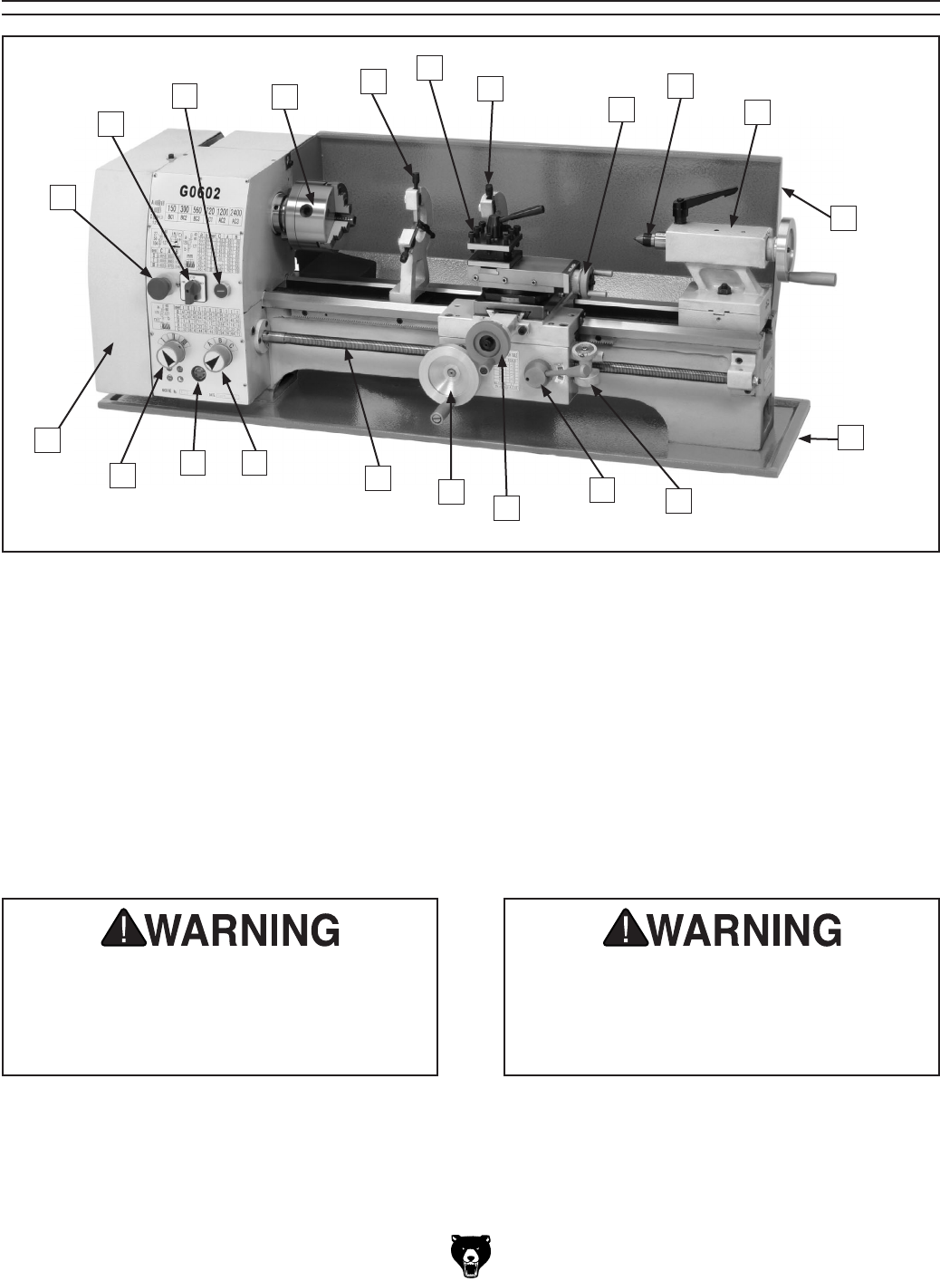
L. Chip Tray
M. Thread Dial
N. Half Nut Lever
O. Cross Slide Handwheel
P. Carriage Handwheel
Q. Leadscrew
R. Alpha Gearbox Dial
S. Gearbox Oil Level Sight Glass
T. Numeric Gearbox Dial
U. Change Gear and Belt Safety Cover
A. Emergency Stop Button
B. Spindle Direction Switch
C. ON Button
D. 3-Jaw Chuck
E. Steady Rest
F. 4-Way Tool Post
G. Follow Rest
H. Compound Rest Handwheel
I. MT#3 Dead Center
J. Tailstock
K. Back Splash
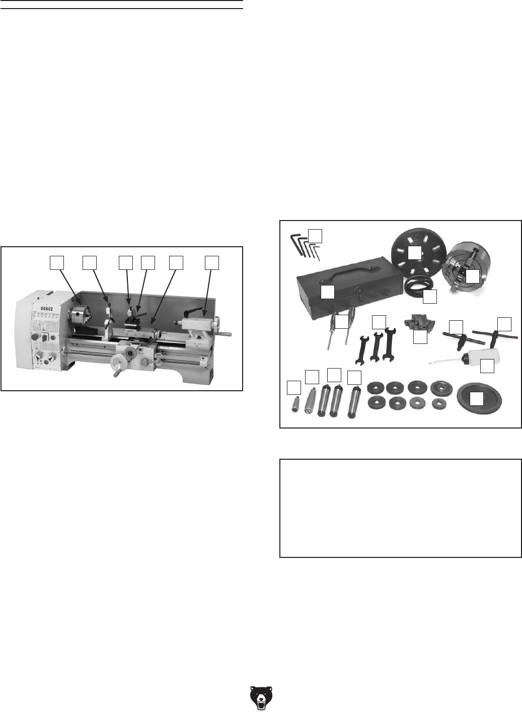
Model G0602 Identification
U
TS R QPONM
L
K
J
I
H
G
F
E
D
C
B
A
Figure 1. G0602 identification.
Serious personal injury could occur if
you connect the machine to power before
completing the setup process. DO NOT
connect power until instructed to do so
later in this manual.
Untrained users have an increased risk
of seriously injuring themselves with this
machine. Do not operate this machine until
you have understood this entire manual
and received proper training.
Model G0602/G0752 (Mfg. Since 11/12) -5-
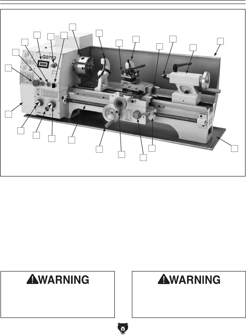
M. Tailstock
N. Back Splash
O. Chip Tray
P. Thread Dial
Q. Half Nut Lever
R. Cross Slide Handwheel
S. Carriage Handwheel
T. Leadscrew
U. Alpha Gearbox Dial
V. Gearbox Oil Level Sight Glass
W. Numeric Gearbox Dial
X. Change Gear and Belt Safety Cover
A. Emergency Stop Button
B. ON Button
C. OFF Button
D. Spindle Speed RPM Display
E. Spindle Speed Dial
F. Spindle Direction Switch
G. 3-Jaw Chuck
H. Steady Rest
I. 4-Way Tool Post
J. Follow Rest
K. Compound Rest Handwheel
L. MT#3 Dead Center
RQ
M
L
I
H
C
B
A
Model G0752 Identification
D
G
F
E
K
Figure 2. G0752 identification.
Serious personal injury could occur if
you connect the machine to power before
completing the setup process. DO NOT
connect power until instructed to do so
later in this manual.
Untrained users have an increased risk
of seriously injuring themselves with this
machine. Do not operate this machine until
you have understood this entire manual
and received proper training.
JN
O
S
T
P
U
V
W
X
-6- Model G0602/G0752 (Mfg. Since 11/12)
Controls &
Components
Refer to Figures 3–8 and the following descrip-
tions to become familiar with the basic controls of
this lathe.
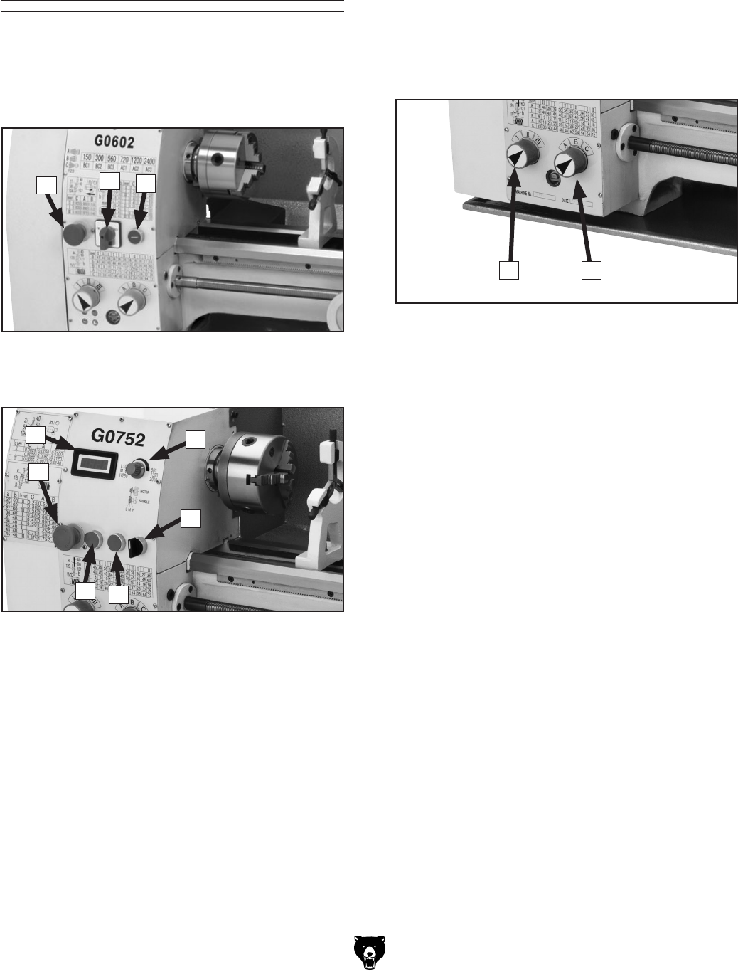
D. OFF Button: Stops spindle rotation.
E. Spindle Speed RPM Display: Shows a digi-
tal readout of the spindle speed.
F. Spindle Speed Dial: Controls the variable
spindle speed.
Model G0752 Control Panel
Figure 4. Model G0752 control panel.
F
E
B
A
CD
Model G0602 Control Panel
Figure 3. Model G0602 control panel.
A. Emergency STOP Button: Cuts power to
the motor and control panel when pressed.
Remains depressed until reset by twisting
clockwise.
B. Spindle Switch: Starts, stops, and reverses
spindle rotation.
C. ON Button: Enables spindle rotation.
ABC
G. Numeric Gearbox Dial: Controls the
leadscrew for threading and feeding opera-
tions. To make a selection, rotate the dial to
the corresponding number displayed on the
threading or feed charts.
H. Alpha Gearbox Dial: Controls the leadscrew
for threading and feeding operations. To
make a selection, rotate the dial to the cor-
responding letter displayed on the threading
or feed charts.
Quick Change Gearbox
Figure 5. Gearbox dials.
G H
Model G0602/G0752 (Mfg. Since 11/12) -7-
Carriage Tailstock
I. 4-Way Tool Post: Holds up to four cutting
tools at once that can be individually indexed
to the workpiece.
J. Compound Rest Handwheel: Moves the
tool toward and away from the workpiece at
the preset angle of the compound rest.
K. Carriage Lock: Secures the carriage for
greater rigidity when it should not move.
L. Thread Dial: Indicates when to engage the
half nut during threading operations.
M. Half Nut Lever: Engages/disengages half
nut for power feed and threading operations.
N. Thread Chart: Indicates which thread dial
mark to use when engaging the half nut for
specific inch thread pitches.
O. Cross Slide Handwheel: Moves the cross
slide toward and away from the workpiece.
P. Carriage Handwheel: Moves the carriage
along the bedway.
Q. Tailstock Quill: Moves a tool or center
mounted in the tailstock toward or away from
the workpiece.
R. Tailstock Quill Lock Lever: Secures the
quill position.
S. Tailstock Lock Nut: Secures the tailstock to
the bedway.
Figure 6. Carriage controls.
I
L
J
M
O
P
K
NT. Tailstock Quill Handwheel: Controls the
movement of the quill.
U. Offset Scale: Indicates the relative distance
of tailstock offset from the spindle centerline.
V. Tailstock Offset Set Screw (1 of 2): Adjusts
the tailstock offset left or right from the spin-
dle centerline.
Change Gears, Pulleys, V-Belt
W. Change Gears: The configuration of the
change gears for power feed, inch, and met-
ric threading controls the leadscrew speed.
X. Pulleys: The position of the V-belt on the pul-
leys controls the spindle speed.
Y. V-Belt: Transfers power from the motor pul-
ley to the spindle pulley. Model G0602 uses
two V-belts. Model G0752 uses one V-belt.
Z. Timing-Belt: (G0602) Transfers power from
the motor to the secondary drive pulley.
Figure 7. Tailstock controls.
Q
ST
U
V
R
Figure 8. Change gears and pulleys
(Model G0602 shown).
X
W
Y
Z

-8- Model G0602/G0752 (Mfg. Since 11/12)
MODEL G0602, G0752
10" x 22" Bench Top Metal Lathe
Model Number G0602 G0752
Product Dimensions
Weight 330 lbs.
Width/Depth/Height 46" x 22" x 16
5⁄8" 50
1⁄2" x 22" x 16
5⁄8"
Foot Print (Width/Depth) 4 7 1⁄2" x 121⁄2"
Shipping Dimensions
Type Wood Crate
Content Machine
Weight 432 lbs. 453 lbs.
Width /Depth/Height 55" x 23" x 22"
Electrical
Power Requirement 110V, Single-Phase, 60 Hz
Minimum Circuit Size 20A 15A
Switch Forward & Reverse Button Switches
Cord Length 5 ft.
Cord Gauge 16 AWG 16 AWG
Plug Included Yes
Included Plug Type NEMA 5-15
Main Motor
Type TEFC Capacitor-Start Induction TEFC Induction
Horsepower 1 HP 1 HP
Phase Single-Phase 3-Phase
Amps 13.6A 12A
Speed 1725 RPM
Power Transfer Cogged Belt Drive
Bearings Shielded & Permanently Sealed
Operation Information
Swing Over Bed 95⁄8"
Distance Between Centers 22 in.
Swing Over Cross Slide 61⁄8 in.
Swing Over Saddle 61⁄8 in.
Maximum Tool Bit Size 1⁄2 in.
Compound Travel 31⁄2
Carriage Travel 181⁄2 in.
Cross Slide Travel 61⁄2 in.

Model G0602/G0752 (Mfg. Since 11/12) -9-
Model Number G0602 G0752
Headstock Information
Spindle Bore 1"
Spindle Size 13⁄4"
Spindle Taper MT#4
Spindle Threads 8 TPI
Number of Spindle Speeds 6 Variable
Range of Spindle Speeds 150 – 2400 RPM 100 – 800, 160 – 1300, 250 – 2000 RPM
Spindle Type Threaded
Spindle Bearings Tapered Roller
Tailstock Information
Tailstock Quill Travel 21⁄2"
Tailstock Taper MT#3
Tailstock Barrel Diameter 1.25"
Threading Information
Number of Longitudinal Feeds 9
Range of Longitudinal Feeds 0.0025 – 0.0140 in./rev.
Number of Inch Threads 33
Range of Inch Threads 8 – 72 TPI
Number of Metric Threads 26
Range of Metric Threads 0.25 – 3.50 mm
Dimensions
Bed Width 61⁄8 in.
Leadscrew Diameter 3⁄4 in.
Leadscrew TPI 12 TPI
Leadscrew Length 34"
Steady Rest Capacity 1⁄4"– 2"
Follow Rest Capacity 1⁄4"– 2"
Faceplate Size 8 in.
Construction
Base Cast Iron
Headstock Cast Iron
Headstock Gears Steel
Bed Hardened and Precision-Ground Cast Iron
Stand Cast Iron
Paint Epoxy
Other
Country of Origin China
Warranty 1 Year
Serial Number Location ID Label on Headstock
Approximate Assembly & Setup
Time 1 Hour

-10- Model G0602/G0752 (Mfg. Since 11/12)
ELECTRICAL EQUIPMENT INJURY RISKS. You
can be shocked, burned, or killed by touching live
electrical components or improperly grounded
machinery. To reduce this risk, only allow qualified
service personnel to do electrical installation or
repair work, and always disconnect power before
accessing or exposing electrical equipment.
DISCONNECT POWER FIRST.
Always discon-
nect machine from power supply BEFORE making
adjustments, changing tooling, or servicing machine.
This prevents an injury risk from unintended startup
or contact with live electrical components.
EYE PROTECTION. Always wear ANSI-approved
safety glasses or a face shield when operating or
observing machinery to reduce the risk of eye
injury or blindness from flying particles. Everyday
eyeglasses are NOT approved safety glasses.
OWNER’S MANUAL. Read and understand this
owner’s manual BEFORE using machine.
TRAINED OPERATORS ONLY. Untrained oper-
ators have a higher risk of being hurt or killed.
Only allow trained/supervised people to use this
machine. When machine is not being used, dis-
connect power, remove switch keys, or lock-out
machine to prevent unauthorized use—especially
around children. Make workshop kid proof!
DANGEROUS ENVIRONMENTS. Do not use
machinery in areas that are wet, cluttered, or have
poor lighting. Operating machinery in these areas
greatly increases the risk of accidents and injury.
MENTAL ALERTNESS REQUIRED. Full mental
alertness is required for safe operation of machin-
ery. Never operate under the influence of drugs or
alcohol, when tired, or when distracted.
For Your Own Safety, Read Instruction
Manual Before Operating This Machine
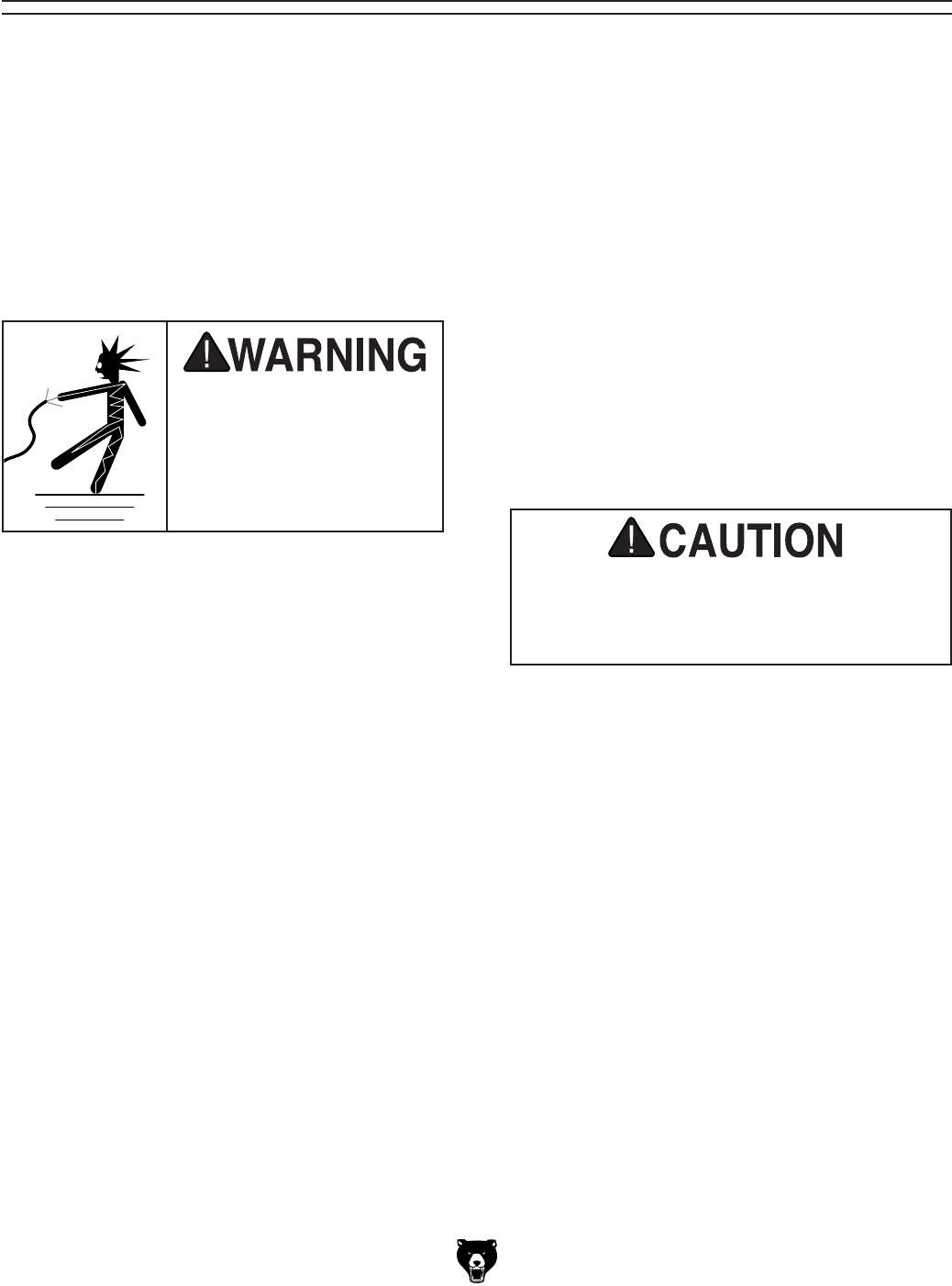
The purpose of safety symbols is to attract your attention to possible hazardous conditions.
This manual uses a series of symbols and signal words intended to convey the level of impor-
tance of the safety messages. The progression of symbols is described below. Remember that
safety messages by themselves do not eliminate danger and are not a substitute for proper
accident prevention measures. Always use common sense and good judgment.
Indicates a potentially hazardous situation which, if not avoided,
MAY result in minor or moderate injury. It may also be used to alert
against unsafe practices.
Indicates a potentially hazardous situation which, if not avoided,
COULD result in death or serious injury.
Indicates an imminently hazardous situation which, if not avoided,
WILL result in death or serious injury.
This symbol is used to alert the user to useful information about
proper operation of the machine.
NOTICE
Safety Instructions for Machinery
SECTION 1: SAFETY

Model G0602/G0752 (Mfg. Since 11/12) -11-
WEARING PROPER APPAREL. Do not wear
clothing, apparel or jewelry that can become
entangled in moving parts. Always tie back or
cover long hair. Wear non-slip footwear to avoid
accidental slips, which could cause loss of work-
piece control.
HAZARDOUS DUST. Dust created while using
machinery may cause cancer, birth defects, or
long-term respiratory damage. Be aware of dust
hazards associated with each workpiece material,
and always wear a NIOSH-approved respirator to
reduce your risk.
HEARING PROTECTION. Always wear hear-
ing protection when operating or observing loud
machinery. Extended exposure to this noise
without hearing protection can cause permanent
hearing loss.
REMOVE ADJUSTING TOOLS. Tools left on
machinery can become dangerous projectiles
upon startup. Never leave chuck keys, wrenches,
or any other tools on machine. Always verify
removal before starting!
USE CORRECT TOOL FOR THE JOB. Only use
this tool for its intended purpose—do not force
it or an attachment to do a job for which it was
not designed. Never make unapproved modifica-
tions—modifying tool or using it differently than
intended may result in malfunction or mechanical
failure that can lead to personal injury or death!
AWKWARD POSITIONS. Keep proper footing
and balance at all times when operating machine.
Do not overreach! Avoid awkward hand positions
that make workpiece control difficult or increase
the risk of accidental injury.
CHILDREN & BYSTANDERS. Keep children and
bystanders at a safe distance from the work area.
Stop using machine if they become a distraction.
GUARDS & COVERS. Guards and covers reduce
accidental contact with moving parts or flying
debris. Make sure they are properly installed,
undamaged, and working correctly.
FORCING MACHINERY. Do not force machine.
It will do the job safer and better at the rate for
which it was designed.
NEVER STAND ON MACHINE. Serious injury
may occur if machine is tipped or if the cutting
tool is unintentionally contacted.
STABLE MACHINE. Unexpected movement dur-
ing operation greatly increases risk of injury or
loss of control. Before starting, verify machine is
stable and mobile base (if used) is locked.
USE RECOMMENDED ACCESSORIES. Consult
this owner’s manual or the manufacturer for rec-
ommended accessories. Using improper acces-
sories will increase the risk of serious injury.
UNATTENDED OPERATION. To reduce the
risk of accidental injury, turn machine OFF and
ensure all moving parts completely stop before
walking away. Never leave machine running
while unattended.
MAINTAIN WITH CARE. Follow all maintenance
instructions and lubrication schedules to keep
machine in good working condition. A machine
that is improperly maintained could malfunction,
leading to serious personal injury or death.
CHECK DAMAGED PARTS. Regularly inspect
machine for any condition that may affect safe
operation. Immediately repair or replace damaged
or mis-adjusted parts before operating machine.
MAINTAIN POWER CORDS. When disconnect-
ing cord-connected machines from power, grab
and pull the plug—NOT the cord. Pulling the cord
may damage the wires inside. Do not handle
cord/plug with wet hands. Avoid cord damage by
keeping it away from heated surfaces, high traffic
areas, harsh chemicals, and wet/damp locations.
EXPERIENCING DIFFICULTIES. If at any time
you experience difficulties performing the intend-
ed operation, stop using the machine! Contact our
Technical Support at (570) 546-9663.

-12- Model G0602/G0752 (Mfg. Since 11/12)
Additional Safety for Metal Lathes
SPEED RATES. Operating the lathe at the wrong
speed can cause nearby parts to break or the
workpiece to come loose, which will result in dan-
gerous projectiles that could cause severe impact
injuries. Large or non-concentric workpieces must
be turned at slow speeds. Always use the appro-
priate feed and speed rates.
CHUCK KEY SAFETY. A chuck key left in the
chuck can become a deadly projectile when the
spindle is started. Always remove the chuck key
after using it. Develop a habit of not taking your
hand off of a chuck key unless it is away from the
machine.
SAFE CLEARANCES. Workpieces that crash
into other components on the lathe may throw
dangerous projectiles in all directions, leading to
impact injury and damaged equipment. Before
starting the spindle, make sure the workpiece has
adequate clearance by hand-rotating it through its
entire range of motion. Also, check the tool and
tool post clearance, chuck clearance, and saddle
clearance.
LONG STOCK SAFETY. Long stock can whip
violently if not properly supported, causing serious
impact injury and damage to the lathe. Reduce this
risk by supporting any stock that extends from the
chuck/headstock more than three times its own
diameter. Always turn long stock at slow speeds.
CRASHES. Aggressively driving the cutting tool or
other lathe components into the chuck may cause
an explosion of metal fragments, which can result
in severe impact injuries and major damage to
the lathe. Reduce this risk by releasing automatic
feeds after use, not leaving lathe unattended, and
checking clearances before starting the lathe.
Make sure no part of the tool, tool holder, com-
pound rest, cross slide, or carriage will contact the
chuck during operation.
SECURING WORKPIECE. An improperly secured
workpiece can fly off the lathe spindle with deadly
force, which can result in a severe impact injury.
Make sure the workpiece is properly secured in the
chuck or faceplate before starting the lathe.
CHUCKS. Chucks are very heavy and difficult to
grasp, which can lead to crushed fingers or hands
if mishandled. Get assistance when handling
chucks to reduce this risk. Protect your hands and
the precision-ground ways by using a chuck cradle
or piece of plywood over the ways of the lathe
when servicing chucks. Use lifting devices when
necessary.
CLEARING CHIPS. Metal chips can easily cut
bare skin—even through a piece of cloth. Avoid
clearing chips by hand or with a rag. Use a brush
or vacuum to clear metal chips.
STOPPING SPINDLE BY HAND. Stopping the
spindle by putting your hand on the workpiece
or chuck creates an extreme risk of entangle-
ment, impact, crushing, friction, or cutting hazards.
Never attempt to slow or stop the lathe spindle with
your hand. Allow the spindle to come to a stop on
its own or use the brake.
TOOL SELECTION. Cutting with an incorrect or
dull tool increases the risk of accidental injury due
to the extra force required for the operation, which
increases the risk of breaking or dislodging com-
ponents that can cause small shards of metal to
become dangerous projectiles. Always select the
right cutter for the job and make sure it is sharp. A
correct, sharp tool decreases strain and provides
a better finish.

Model G0602/G0752 (Mfg. Since 11/12) -13-
The following is a list of common definitions, terms and phrases used throughout this manual as they relate
to this lathe and metalworking in general. Become familiar with these terms for assembling, adjusting or
operating this machine. Your safety is VERY important to us at Grizzly!
Arbor: A machine shaft that supports a cutting
tool.
Backlash: Wear in a screw or gear mechanism
that may result in slippage, vibration, and loss
of tolerance.
Carriage: A main housing that consists of the
apron and the saddle.
Cross Slide: A fixture attached to the lathe car-
riage that holds the compound rest and can be
moved in and out.
Compound Rest: A fixture attached to the cross
slide that holds the tool holder and can be
moved in and out.
Cutting Speed: The distance a point on a cutter
moves in one minute, expressed in meters or
feet per minute.
Dial Indicator: An instrument used in setup
and inspection work that shows on a dial the
amount of error in size or alignment of a part.
Facing: In lathe work, cutting across the end of
a workpiece, usually to machine a flat surface.
Feed: The movement of a cutting tool into a
workpiece.
Fixture: A device that securely holds the
workpiece in place during cutting operation
as opposed to a jig which is used to hold and
guide a workpiece through an operation.
Gib: A tapered wedge located along a sliding
member to take up wear or to ensure a proper
fit.
Headstock: The major lathe component that
houses the spindle and motor drive system to
turn the workpiece.
Lathe Center: A lathe accessory with a 60°
point which is inserted into the headstock or
tailstock of the lathe and is used to support the
workpiece.
Leadscrew: Lathe—The long screw that is driv-
en by the change gears and supplies power to
the carriage.
Saddle: The upper portion of carriage that rides
on the lathe ways and supports the cross feed
and the follow rest.
Spindle: The revolving shaft that holds and
drives the workpiece or cutting tool.
Tailstock: A moveable fixture opposite of the
headstock on a lathe that has a spindle used
to support one end of a workpiece and for hold-
ing tools.
Tool Post: The part of the compound rest that
holds the tool holder.
Turret : Lathe—A machine fixture that holds mul-
tiple tools and can be revolved and indexed to
position.
Ways: The precision machined and flat tracks
on a lathe on which the carriage and tailstock
slide.
Glossary of Terms
-14- Model G0602/G0752 (Mfg. Since 11/12)
SECTION 2: POWER SUPPLY
Availability
Before installing the machine, consider the avail-
ability and proximity of the required power supply
circuit. If an existing circuit does not meet the
requirements for this machine, a new circuit must
be installed. To minimize the risk of electrocution,
fire, or equipment damage, installation work and
electrical wiring must be done by an electrican or
qualified service personnel in accordance with all
applicable codes and standards.
Electrocution, fire, or
equipment damage may
occur if machine is not
correctly grounded and
connected to the power
supply.
Full-Load Current Rating
The full-load current rating is the amperage a
machine draws at 100% of the rated output power.
On machines with multiple motors, this is the
amperage drawn by the largest motor or sum of all
motors and electrical devices that might operate
at one time during normal operations.
G0602 Full-Load Rating ...........................13.6A
G0752 Full-Load Rating ..............................12A
The full-load current is not the maximum amount
of amps that the machine will draw. If the machine
is overloaded, it will draw additional amps beyond
the full-load rating.
If the machine is overloaded for a sufficient length
of time, damage, overheating, or fire may result—
especially if connected to an undersized circuit.
To reduce the risk of these hazards, avoid over-
loading the machine during operation and make
sure it is connected to a power supply circuit that
meets the requirements in the following section.
For your own safety and protection of
property, consult an electrician if you are
unsure about wiring practices or electrical
codes in your area.
Note: The circuit requirements listed in this man-
ual apply to a dedicated circuit—where only one
machine will be running at a time. If this machine
will be connected to a shared circuit where mul-
tiple machines will be running at the same time,
consult a qualified electrician to ensure that the
circuit is properly sized for safe operation.
A power supply circuit includes all electrical
equipment between the main breaker box or fuse
panel in your building and the incoming power
connections inside the machine. This circuit must
be safely sized to handle the full-load current that
may be drawn from the machine for an extended
period of time.
Circuit Requirements
This machine is prewired to operate on a 110V
power supply circuit that has a verified ground and
meets the following requirements:
Nominal Voltage ...............................110V/120V
Cycle ..........................................................60 Hz
Phase ........................................... Single-Phase
Minimum Circuit Size (G0602) .......... 20 Amps
Minimum Circuit Size (G0752) .......... 15 Amps
Model G0602/G0752 (Mfg. Since 11/12) -15-
Improper connection of the equipment-grounding
wire can result in a risk of electric shock. The
wire with green insulation (with or without yellow
stripes) is the equipment-grounding wire. If repair
or replacement of the power cord or plug is nec-
essary, do not connect the equipment-grounding
wire to a live (current carrying) terminal.
Check with a qualified electrician or service per-
sonnel if you do not understand these grounding
requirements, or if you are in doubt about whether
the tool is properly grounded. If you ever notice
that a cord or plug is damaged or worn, discon-
nect it from power, and immediately replace it with
a new one.
Extension Cords
We do not recommend using an extension cord
with this machine.
If you must use an extension
cord, only use it if absolutely necessary and only
on a temporary basis.
Extension cords cause voltage drop, which may
damage electrical components and shorten motor
life. Voltage drop increases as the extension cord
size gets longer and the gauge size gets smaller
(higher gauge numbers indicate smaller sizes).
Any extension cord used with this machine must
contain a ground wire, match the required plug
and receptacle, and meet the following require-
ments:
Minimum Gauge Size ...........................14 AWG
Maximum Length (Shorter is Better).......50 ft.
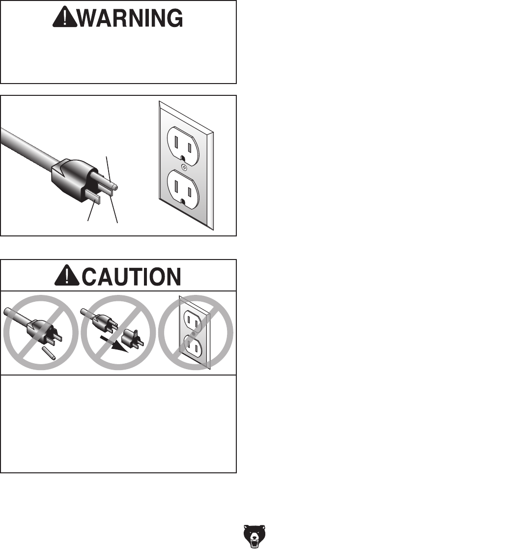
Figure 9. Included 5-15 plug and receptacle.
Grounding Prong
Neutral Hot
5-15 PLUG
GROUNDED
5-15 RECEPTACLE
Serious injury could occur if you connect
the machine to power before completing the
setup process. DO NOT connect to power
until instructed later in this manual.
SHOCK HAZARD!
Two-prong outlets do not meet the grounding
requirements for this machine. Do not modify
or use an adapter on the plug provided—if
it will not fit the outlet, have a qualified
electrician install the proper outlet with a
verified ground.
Grounding & Plug Requirements
This machine MUST be grounded. In the event
of certain malfunctions or breakdowns, grounding
reduces the risk of electric shock by providing a
path of least resistance for electric current.
This machine is equipped with a power cord that
has an equipment-grounding wire and a ground-
ing plug (similar to the figure below). The plug
must only be inserted into a matching receptacle
(outlet) that is properly installed and grounded in
accordance with all local codes and ordinances.
-16 - Model G0602/G0752 (Mfg. Since 11/12)
SECTION 3: SETUP
Your machine was carefully packaged for safe
transportation. Remove the packaging materials
from around your machine and inspect it. If you
discover any damage, please call us immediately
at (570) 546-9663
for advice.
Save the containers and all packing materials for
possible inspection by the carrier or its agent.
Otherwise, filing a freight claim can be difficult.
When you are completely satisfied with the condi-
tion of your shipment, inventory the contents.
Unpacking
SUFFOCATION HAZARD!
Keep children and pets away
from plastic bags or packing
materials shipped with this
machine. Discard immediately.
The following are needed to complete the setup
process, but are not included with your machine.
Description Qty
• Additional People ....................................... 1
• Safety Glasses ............... 1 For Each Person
• Cleaner/Degreaser (Page 18) .... As Needed
• Quality Metal Protectant ............. As Needed
• Disposable Shop Rags ............... As Needed
• Precision Level ........................................... 1
• Lifting Straps (rated for at least 500 lbs.) ... 2
• Forklift/Power Lifting Device (rated for at least
500 lbs.) ...................................................... 1
• Bench Mounting Hardware ........ As Needed
Needed for Setup
Model G0602/G0752 (Mfg. Since 11/12) -17-
Inventory
The following is a list of items shipped with your
machine. Before beginning setup, lay these items
out and inventory them.
If any non-proprietary parts are missing (e.g. a
nut or a washer), we will gladly replace them; or
for the sake of expediency, replacements can be
obtained at your local hardware store.
Installed Components (Figure 10) Qty.
A. 5" Three-Jaw Chuck ................................... 1
B. Steady Rest ................................................ 1
C. Follow Rest ................................................. 1
D. 4-Way Tool Post ......................................... 1
E. Compound Rest ......................................... 1
F. Tailstock ...................................................... 1
Figure 11. Packaged components.
I
J
K
L
MN
OPQ
R
S
UV
W
H
T
NOTICE
If you cannot find an item on this list, care-
fully check around/inside the machine and
packaging materials. Often, these items get
lost in packaging materials while unpack-
ing or they are pre-installed at the factory.
Figure 10. Installed components.
D EA B C F
Packaged Components (Figure 11) Qty.
G. Chip Pan (Not Shown) ................................ 1
H. Hex Wrench Set (2.5, 3, 4, 5, 6 mm) .....1 Ea
I. Toolbox ....................................................... 1
J. 8" Faceplate ............................................... 1
K. 61⁄2" 4-Jaw Independent Chuck .................. 1
L. Low Range Belt 271⁄2" (G0602) .................. 1
High Range Belt 33" (Installed, G0602) ..... 1
V-Belt 33" (Installed, G0752) ...................... 1
M. #2 Phillips and Standard Screwdriver ...1 Ea
N. Wrench Set (8/10, 12/14, 19/17mm) .......1 Ea
O. 3-Jaw Chuck Internal Jaw Set .................... 1
P. 3-Jaw Chuck Key ....................................... 1
Q 4-Jaw Chuck Key ....................................... 1
R. Oil Bottle for Oil .......................................... 1
S. Cross Slide Handwheel Handle ................. 1
T. Carriage Handwheel Handle ...................... 1
U. Dead Centers MT#3 .................................. 2
V. Dead Center MT#4 ..................................... 1
W. Change Gear Set ....................................... 1
— Change Gear (27-tooth, Installed) ......... 1
— Change Gear (36-tooth) ......................... 1
— Change Gear (40-tooth) ......................... 1
— Change Gear (44-tooth) ......................... 1
— Change Gear (45-tooth) ......................... 1
— Change Gear (46-tooth) ......................... 1
— Change Gear (48-tooth) ......................... 1
— Change Gear (52-tooth) ......................... 1
— Change Gear (56-tooth, Installed) ......... 1
— Change Gear (60-tooth) ......................... 1
— Plastic Drive Gear (60-tooth, Installed) . . 1
— Change Gear (104-tooth, Installed) ....... 1
— Change Gear (120-tooth) ....................... 1
— Change Gear (127-tooth, Installed) ........ 1
X. Frequency Drive Manual VFD-E (G0752, Not
Shown) ....................................................... 1
-18- Model G0602/G0752 (Mfg. Since 11/12)
The unpainted surfaces of your machine are
coated with a heavy-duty rust preventative that
prevents corrosion during shipment and storage.
This rust preventative works extremely well, but it
will take a little time to clean.
Be patient and do a thorough job cleaning your
machine. The time you spend doing this now will
give you a better appreciation for the proper care
of your machine's unpainted surfaces.
There are many ways to remove this rust preven
-
tative, but the following steps work well in a wide
variety of situations. Always follow the manufac
-
turer’s instructions with any cleaning product you
use and make sure you work in a well-ventilated
area to minimize exposure to toxic fumes.
Before cleaning, gather the following:
•
Disposable Rags
•
Cleaner/degreaser (WD•40 works well)
•
Safety glasses & disposable gloves
•
Plastic paint scraper (optional)
Basic steps for removing rust preventative:
1.
Put on safety glasses.
2.
Coat the rust preventative with a liberal
amount of cleaner/degreaser, then let it soak
for 5–10 minutes.
3.
Wipe off the surfaces. If your cleaner/degreas-
er is effective, the rust preventative will wipe
off easily. If you have a plastic paint scraper,
scrape off as much as you can first, then wipe
off the rest with the rag.
4.
Repeat Steps 2–3 as necessary until clean,
then coat all unpainted surfaces with a quality
metal protectant to prevent rust.
Gasoline or products
with low flash points can
explode or cause fire if
used to clean machin-
ery. Avoid cleaning with
these products.
Many cleaning solvents
are toxic if concentrat-
ed amounts are inhaled.
Only work in a well-venti-
lated area.
NOTICE
Avoid chlorine-based solvents, such as
acetone or brake parts cleaner, that may
damage painted surfaces. Test all cleaners
in an inconspicuous area before using to
make sure they will not damage paint.
Cleanup
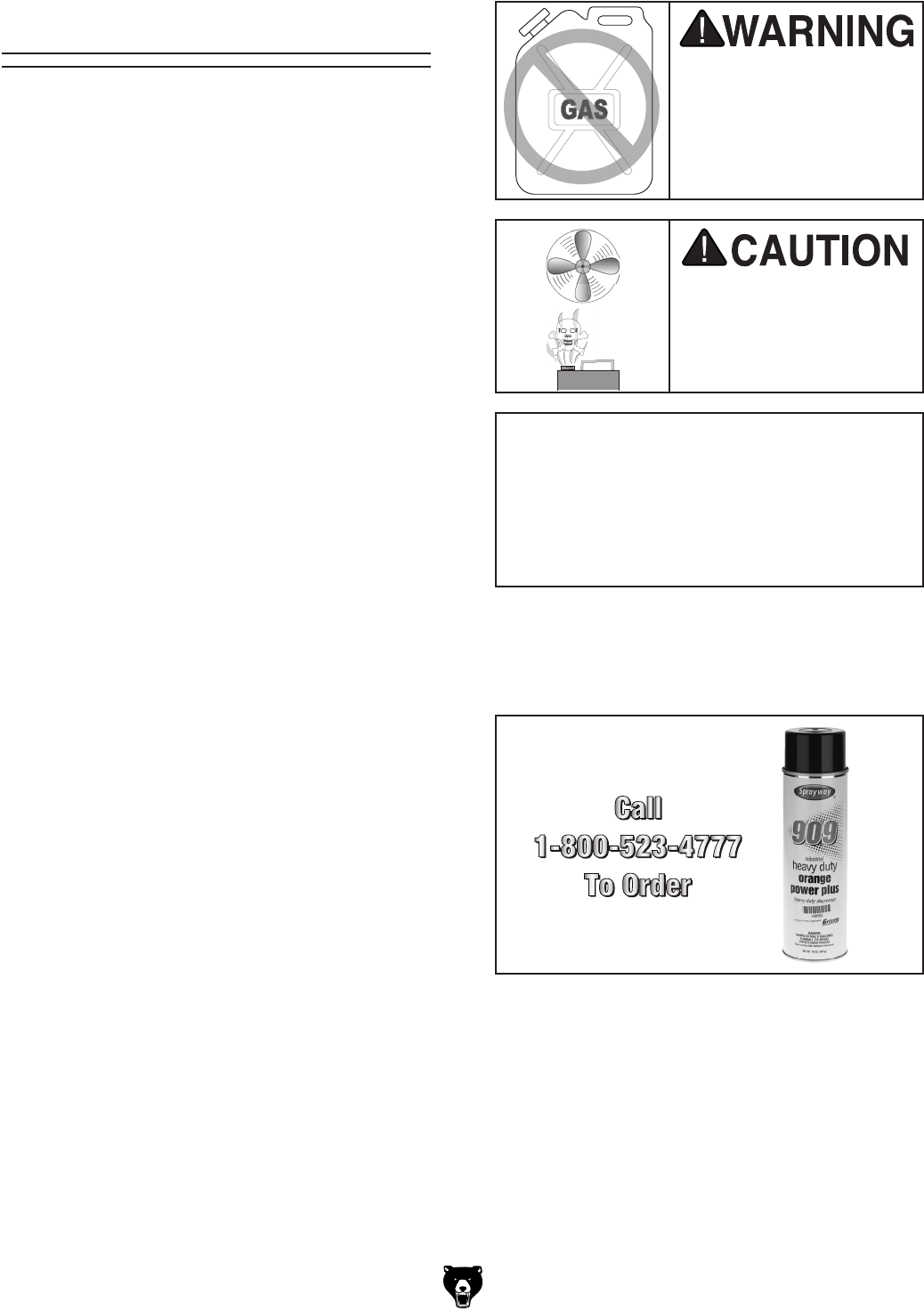
T23692—Orange Power Degreaser
A great product for removing the waxy shipping
grease from your machine during clean up.
Figure 12. T23692 Orange Power Degreaser.
Model G0602/G0752 (Mfg. Since 11/12) -19-
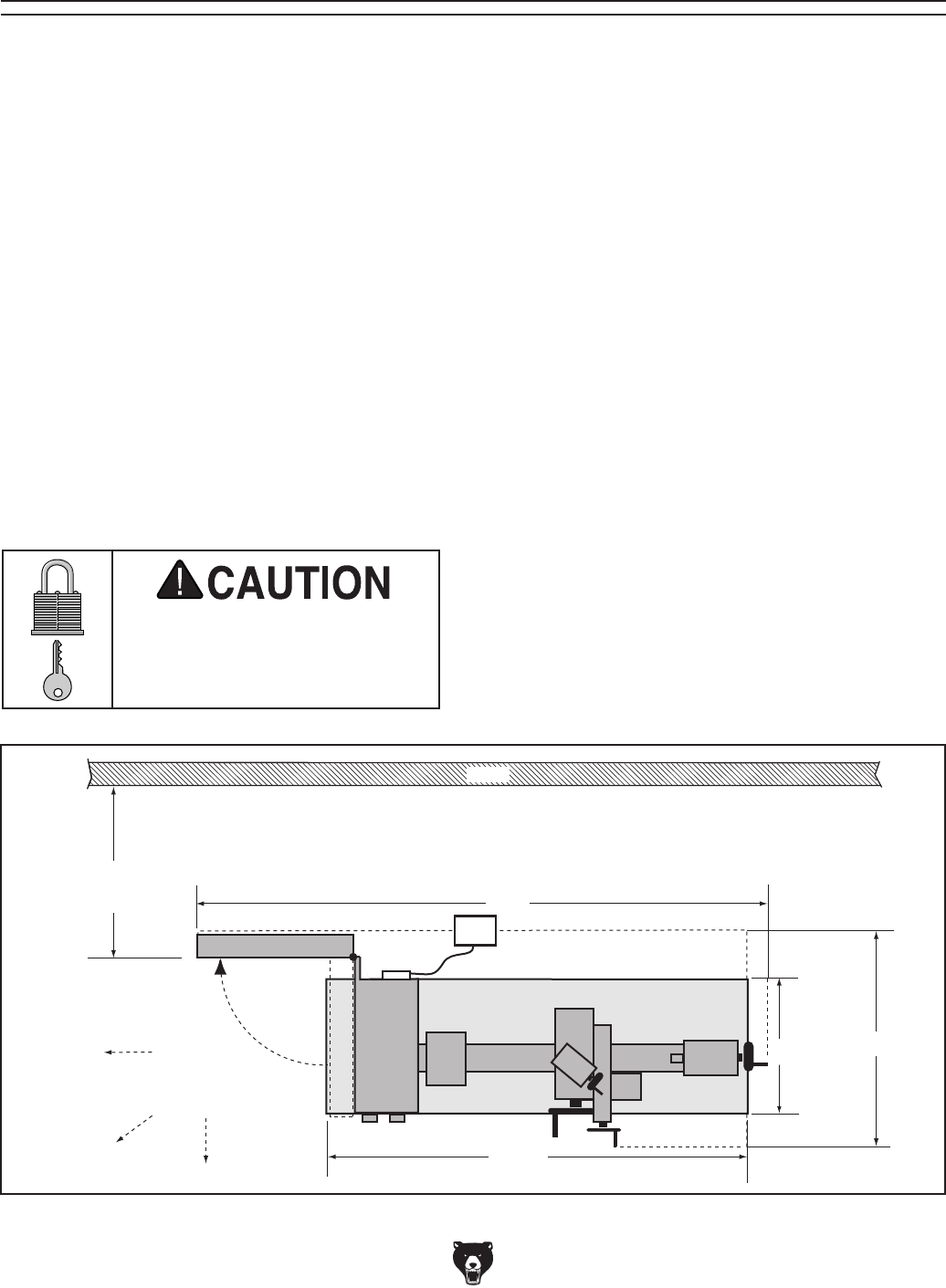
12.5" 30"
47.5"
65"
Keep
Workpiece
Loading Area
Unobstructed
Access
Door Lathe
110V
Supply
Footprint
Footprint
18"
Wall
Min. 30"
for Maintenance
Figure 13. Minimum working clearances.
Site Considerations
Weight Load
Refer to the Machine Data Sheet for the weight
of your machine. Make sure that the surface upon
which the machine is placed will bear the weight
of the machine, additional equipment that may be
installed on the machine, and the heaviest work-
piece that will be used. Additionally, consider the
weight of the operator and any dynamic loading
that may occur when operating the machine.
Space Allocation
Consider the largest size of workpiece that will
be processed through this machine and provide
enough space around the machine for adequate
operator material handling or the installation of
auxiliary equipment. With permanent installations,
leave enough space around the machine to open
or remove doors/covers as required by the main-
tenance and service described in this manual.
See below for required space allocation.
Physical Environment
The physical environment where the machine is
operated is important for safe operation and lon-
gevity of machine components. For best results,
operate this machine in a dry environment that is
free from excessive moisture, hazardous chemi-
cals, airborne abrasives, or extreme conditions.
Extreme conditions for this type of machinery are
generally those where the ambient temperature
range exceeds 41°–104°F; the relative humidity
range exceeds 20–95% (non-condensing); or the
environment is subject to vibration, shocks, or
bumps.
Electrical Installation
Place this machine near an existing power source.
Make sure all power cords are protected from
traffic, material handling, moisture, chemicals,
or other hazards. Make sure to leave access to
a means of disconnecting the power source or
engaging a lockout/tagout device, if required.
Lighting
Lighting around the machine must be adequate
enough that operations can be performed safely.
Shadows, glare, or strobe effects that may distract
or impede the operator must be eliminated.
Children or untrained people
may be seriously injured by
this machine. Only install in an
access restricted location.
-20- Model G0602/G0752 (Mfg. Since 11/12)
Lifting & Placing
HEAVY LIFT!
Straining or crushing injury
may occur from improperly
lifting machine or some of
its parts. To reduce this risk,
get help from other people
and use a forklift (or other
lifting equipment) rated for
weight of this machine.
Do not attempt to lift or move this lathe without
using the proper lifting equipment (such as forklift
or crane) or the necessary assistance from other
people. Refer to Needed for Setup on Page 16
for details.
To lift and move the lathe:
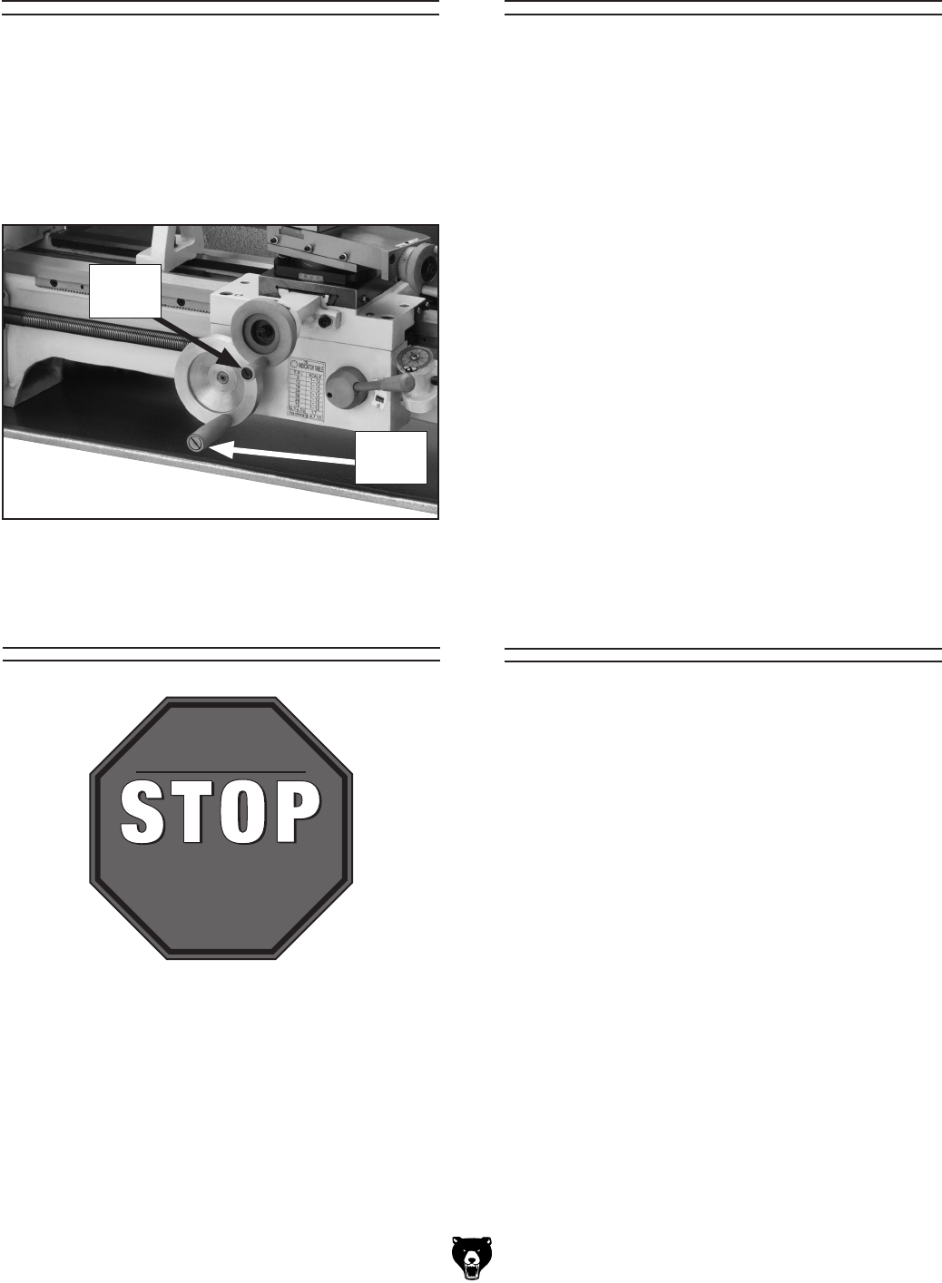
1. Remove the shipping crate top and sides,
then remove the chip pan, 4-jaw chuck, face-
plate, and toolbox from the shipping pallet.
2. Position the chip pan on the selected mount-
ing surface and use it as a template to mark
the hole locations for the mounting hardware
(refer to Leveling & Mounting on Page 21).
3. Unbolt the lathe from the shipping pallet.
5. Wrap the lifting straps around the bed and
between the leadscrew and the bedway, as
shown in Figure 14, to help prevent bending
the leadscrew during lifting.
6. Attach the lifting straps to the power lifting
equipment, have an assistant steady the
load, then lift it just enough to clear any
obstacles and move it to its mounting posi-
tion.
7. Properly mount the lathe as instructed in the
Mounting subsection on Page 21.
Figure 14. Example of lifting strap positions.
4. To balance the load for lifting, move the
tailstock and carriage to the extreme right
end of the bedway, then lock them in place.
Note: Before attempting to move the car-
riage, make sure the carriage lock is loose
and the half nut is disengaged.
Only use lifting straps and power lifting
equipment rated for at least 500 lbs. and in
good working condition. If the lathe falls or
tips over while moving it, serious personal
injury and property damage could result.
Model G0602/G0752 (Mfg. Since 11/12) -21-
The chip pan and the base of the lathe have
holes that allow the machine to be mounted to
a workbench. You MUST mount your machine
to a workbench to prevent it from unexpectedly
moving during operation, which could lead to
personal injury or property damage.
Follow these guidelines when mounting your
lathe to ensure safe and accurate cutting
results:
• Make sure that the workbench can adequate-
ly support the weight of the machine and
materials and that it will not move or vibrate
during operation.
• Use a silicon sealant between the lathe and
the chip pan to prevent coolant or other fluids
from leaking through onto the bench or floor.
To mount the lathe and chip pan to the workbench,
drill holes all the way through the workbench, and
use hex bolts, washers, and hex nuts to secure
the lathe to the workbench, as illustrated in
Figure 16.
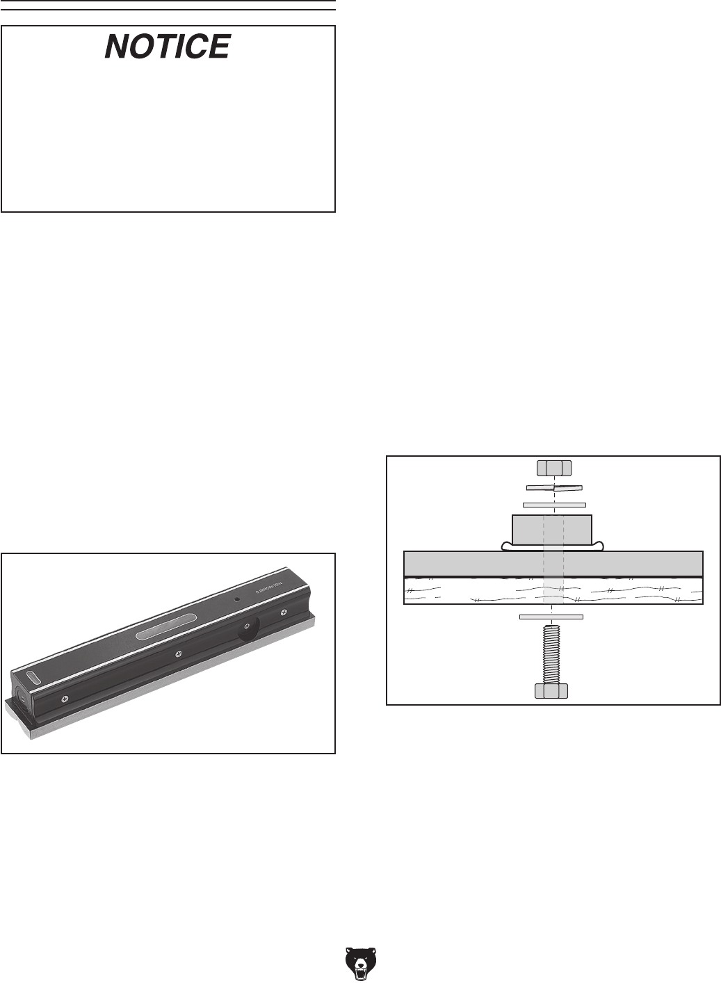
Leveling & Mounting
Figure 15. Grizzly Model H2683 12" Master
Machinist's Level.
Leveling machinery helps precision components,
such as bedways, remain straight and flat during
the lifespan of the machine. Components on a
machine that is not level may slowly twist due to
the dynamic loads placed on the machine during
operation.
For best results, use a precision level that is at
least 12" long and sensitive enough to show a
distinct movement when a 0.003" shim (approxi-
mately the thickness of one sheet of standard
newspaper) is placed under one end of the level.
See the figure below for an example of a high
precision level.
Leveling
Mounting
Chip Pan
Workbench
Hex Bolt
Flat Washer
Flat Washer
Silicon
Lock Washer
Hex Nut
Lathe
Figure 16. Example of a through mount setup.
For accurate turning results and to prevent
warping the cast iron bed and ways, the lathe
bedways MUST be leveled from side-to-side
and from front-to-back on both ends.
Re-check the bedways 24 hours after
installation, two weeks after that, and then
annually to make sure they remain level.
-22- Model G0602/G0752 (Mfg. Since 11/12)
Power Connection
Lubricating Lathe
The lathe must be properly lubricated before it can
be operated for the first time.
Damage caused to the bearings and gears from
running the lathe without oil in the reservoirs
will not be covered under warranty. Refer to the
Lubrication section, beginning on Page 52, for
details on how to lubricate the lathe.
GEARBOX MUST
BE FILLED WITH OIL!
LATHE MAY NOT
HAVE OIL INCLUDED!
Refer to the Lubrication
Section in this Manual
for Recommended
Oil Type.
Assembly
With the exception of the handwheel handles, the
lathe is shipped fully assembled.
To install the handwheel handles, thread the large
handle into the carriage handwheel and the small
handle into the cross slide handwheel, as shown
in Figure 17.
Figure 17. Handwheel handles installed.
Before the machine can be connected to the
power source, an electrical circuit and connec-
tion device must be prepared per the POWER
SUPPLY section in this manual, and all previ-
ous setup instructions in this manual must be
completed to ensure that the machine has been
assembled and installed properly.
Connecting Power
Always make sure the spindle direction switch on
the front of the headstock is turned OFF (middle
position) before connecting power.
Insert the power cord plug into a matching power
supply receptacle.
Disconnecting Power
If you need to disconnect the machine from power
for maintenance, service, or adjustments, turn the
machine off and pull the plug completely out of
the receptacle.
Once the assembly is complete, test run your
machine to make sure it runs properly and is
ready for regular operation.
The test run consist of verifying the following: 1)
The motor powers up and runs correctly, 2) the
emergency STOP button safety feature works
correctly.
If, during the test run, you cannot easily locate
the source of an unusual noise or vibration, stop
using the machine immediately, then review
Troubleshooting on Page 57.
If you still cannot remedy a problem, contact our
Tech Support at (570) 546-9663 for assistance.
Test Run
Large
Handle
Small
Handle
Model G0602/G0752 (Mfg. Since 11/12) -23-
7. Reset the emergency STOP button by twist-
ing it clockwise until it pops out.
To test run your machine:
1. Make sure the spindle direction switch (see
Figure 18) is turned to STOP, and press the
emergency STOP button.
5. Set lathe spindle speed for 150 RPM, (refer
to Setting Spindle Speed on Page 42).
6. Disengage the half nut with the lever shown
in Figure 19.
Figure 18. Headstock and gearbox controls.
3. Clear away all tools and objects used during
assembly, lubrication, and preparation.
4. Make sure chuck and jaws, if installed, are
secure (see Chuck Installation on Page 27).
Note: If a chuck is not installed on the lathe,
you do not need to install one for this test.
2. Read and follow the safety instructions at the
beginning of the manual, take all required
safety precautions, and make sure all pre-
vious preparation steps discussed in this
manual have been followed and completed.
Emergency
Stop Button
Spindle Direction Switch
Pointing to STOP
8. G0752 Only: Ensure the spindle speed dial is
turned all the way counterclockwise.
Push the green ON button, then turn the
spindle direction switch to FWD. Turn the
spindle speed dial until the spindle speed
display shows 150 RPM. The spindle should
be rotating counterclockwise—down and
toward you as you face the lathe.
G0602: Push the green ON button, then turn
the spindle direction switch to FWD. The
spindle should be rotating counterclockwise—
down and toward you as you face the lathe.
9. Push the emergency STOP button to turn the
lathe OFF, then, without resetting the STOP
button, try to restart spindle rotation. The
spindle should not start.
— If spindle rotation does start with the
emergency STOP button pressed in, the
button is not operating correctly. This
safety feature must operate properly
before continuing operation. Use the
spindle direction switch to stop the lathe,
disconnect it from power, and call Tech
Support for help.
Congratulations! The test run is complete. Turn
the lathe OFF and perform the following Spindle
Break-In procedure.
ON
Button
Figure 19. Half nut lever in the disengaged
position.
Engaged
Halfnut
Lever
Disengaged
Half Nut
Lever

-24- Model G0602/G0752 (Mfg. Since 11/12)
Before subjecting the lathe to full loads, it is essen-
tial to complete the spindle break-in process. This
will ensure the best results and maximum life of
the precision components inside the lathe.
The break-in procedure must be performed in
succession with the Test Run procedure because
many of the test run steps prepare the lathe con-
trols for the break-in process.
Important: Do not perform the break-in procedure
independently from the Test Run section—seri-
ous damage could occur to the lathe if the controls
are set differently than instructed in that section.
Spindle Break-In
To perform the spindle break-in:
1. Operate the lathe at 150 RPM for 10 minutes.
2. G0602: Repeat Step 1 at each of the following
speeds 300, 560, 720, 1200, and 2400.
G0752: Repeat Step 1 at each of the following
approximate speeds: 800, 1300, and 2000.
3. When the spindle has come to a complete
stop, run the spindle in reverse at 2400 RPM
(Model G0602) or 2000 RPM (Model G0752)
for another 10 minutes, then press the
emergency STOP button and DISCONNECT
THE LATHE FROM POWER!
4. Check, and if necessary, re-tension the drive
belts (refer to V-Belt Tension & Replacement
Page 64 on page for detailed instructions.)
5. While the oil is still warm and any metal par-
ticles are still suspended in the oil, change
the gearbox oil (refer to Lubrication on Page
52 for detailed instructions).
Congratulations! The spindle break-in is com-
plete. Continue with the following Recommended
Adjustments subsection.
Recommended
Adjustments
For your convenience, the adjustments listed
below have been performed at the factory.
However, because of the many variables involved
with shipping, we recommend that you at least
verify the following adjustments to ensure the best
possible results from your new machine. Step-
by-step instructions for these adjustments can be
found on the pages referenced below.
Factory adjustments that should be verified:
• Tailstock alignment (Page 33)
• Gib adjustments (Page 61)
• Backlash adjustment (Page 60)
Model G0602/G0752 (Mfg. Since 11/12) -25-
Complete the Test Run & Break-In proce-
dure on Pages 22– 24 before using this lathe
for any cutting or threading operations; oth-
erwise, gear box damage will occur.
SECTION 4: OPERATIONS
Operation Overview
The purpose of this overview is to provide the nov-
ice machine operator with a basic understanding
of how the machine is used during operation, so
the
machine controls/components
discussed later
in this manual
are easier to understand.
Due to the generic nature of this overview, it is
not intended to be an instructional guide. To learn
more about specific operations, read this entire
manual and
seek additional training from expe
-
rienced
machine operators, and do additional
research outside of this manual by reading "how-
to" books, trade magazines, or websites.
To reduce your risk of
serious injury, read this
entire manual BEFORE
using machine.
If you are not experienced with this type
of machine, WE STRONGLY RECOMMEND
that you seek additional training outside of
this manual. Read books/magazines or get
formal training before beginning any proj-
ects. Regardless of the content in this sec-
tion, Grizzly Industrial will not be held liable
for accidents caused by lack of training.
To reduce risk of eye injury
from flying chips always
wear safety glasses or face
shield when operating.
To complete a typical operation, the operator
does the following:
1. Puts on safety glasses, rolls up sleeves,
removes jewelry, and secures any clothing,
jewelry, or hair that could get entangled in
moving parts.
2. Examines the workpiece to make sure it is
suitable for turning, then securely mounts the
workpiece in a chuck, between centers, or on
the faceplate.
3. Mounts the tooling, aligns it with the workpiece,
then backs it away to establish a safe startup
clearance.
4. Clears all setup tools from the lathe.
5. Checks for safe clearances by rotating the
workpiece by hand at least one full revolution.
6. Sets the correct spindle speed for the opera-
tion.
7. If using power feed, selects the proper feed
rate for the operation.
8. Starts spindle rotation, then engages the half
nut.
9. Uses various carriage controls to move the
tooling into the workpiece for operations.
10. When finished cutting, disengages the half
nut (power feed only), moves the spindle
direction switch to the OFF position, waits for
the spindle to completely stop, then removes
the workpiece.
-26- Model G0602/G0752 (Mfg. Since 11/12)
This lathe ships with the 3-jaw chuck installed.
This is a scroll-type chuck where all three jaws
move in unison when the chuck key is used.
The included 4-jaw chuck features independent
jaws, which are used for square or unevenly-
shaped stock, and to mount work that needs to be
adjusted to near zero total indicated runout.
If neither chuck can hold your workpiece, the
cast iron faceplate has slots for T-bolts that hold
standard or custom clamping hardware. With the
correct clamping hardware, a faceplate offers a
wide range of uses, including machining non-
concentric workpieces, straight turning between
centers, off-center turning, and boring.
This lathe is equipped with a threaded spindle
nose. With this type of spindle, a chuck or face-
plate is screwed directly onto the spindle nose.
Never use spindle speeds faster than the
chuck RPM rating or the safe limits of
your workpiece. Excessive spindle speeds
greatly increase the risk of the workpiece or
chuck being thrown from the machine with
deadly force!
Chuck & Faceplate
Mounting
Installation &
Removal Devices
Pre-Threaded Hole
for Lifting Eye
Way Slot
Jaw Slot
Plywood & 2x4
Chuck Cradle
Plywood Chuck Cradle
(Straight Cuts)
Plywood Chuck Cradle
(Curved Cuts)
Fabricated Steel
Lifting Hook
Solid Block
Chuck Cradle
Plywood Protection
Plate for Chucks
Installed by Hand
MEDIUM-SIZE, HEAVY CHUCKS
LARGE, VERY HEAVY CHUCKS
SMALL, LIGHTWEIGHT CHUCKS
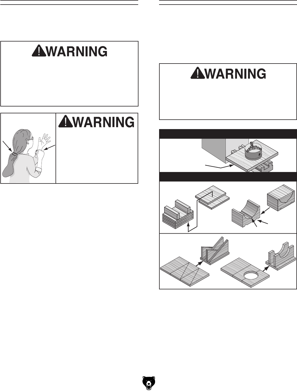
Figure 20. Examples of common devices used
during chuck installation and removal.
A dropped chuck can cause amputation,
serious crushing injuries, or property dam-
age. Always use a support or protective
device to reduce this risk when installing or
removing a chuck.
Loose hair, clothing, or
jewelry could get caught
in machinery and cause
serious personal injury.
Keep these items away
from moving parts at all
times to reduce this risk.
Because chucks are heavy and often awkward to
hold, some kind of support or protective device
should be used during installation or removal. The
weight and size of the chuck will determine the
appropriate device to use (refer to the following
figure for examples).
Model G0602/G0752 (Mfg. Since 11/12) -27-
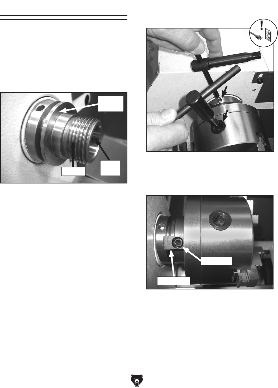
Chuck Installation 5. Insert the chuck wrenches as shown in
Figure 22, and tighten the chuck until it is
seated snug against the spindle shoulder.
Figure 22. Location to insert chuck keys when
installing chuck.
To ensure accurate work, it is extremely important
to make sure the spindle nose and chuck mating
surfaces are clean. Even a small amount of lint or
debris can affect accuracy.
The chuck is properly installed when it threads
all the way onto the spindle nose (see Figure 21
below) and is seated against the spindle shoulder.
6. Install the chuck locks with the cap screws
(see Figure 23).
Figure 23. Chuck lock installed on spindle nose
and chuck.
Chuck Lock
Cap Screw
4. Thread the chuck onto the spindle nose and
hand-tighten it.
3. Thoroughly clean, inspect, deburr, and lightly
oil all threads and mating surfaces.
To install the chuck:
1. DISCONNECT LATHE FROM POWER!
2. Use an appropriate device to protect the ways
and support the chuck during the installation
process (refer to Installation & Removal
Devices on Page 26).
Tools Needed: Qty
Chuck Wrenches ............................................... 2
Hex Wrench 5mm .............................................. 1
Figure 21. Spindle nose.
Threads
Inside
Taper
Spindle
Shoulder
-28- Model G0602/G0752 (Mfg. Since 11/12)
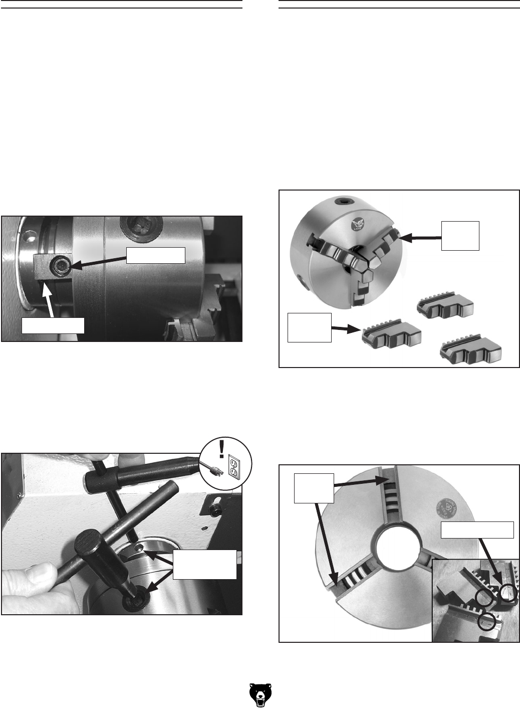
Figure 25. Location to insert chuck keys when
removing chuck.
Figure 24. Location of chuck lock and cap
screws.
Chuck Lock
Cap Screw
4. Insert the chuck wrenches, as shown in
Figure 25, then while holding the spindle,
unthread the chuck in a counterclockwise
direction.
5. Support the chuck, unscrew it, and remove.
To remove the chuck:
1. DISCONNECT LATHE FROM POWER!
2. Use an appropriate device to protect the ways
and support the chuck (refer to Installation &
Removal Devices on Page 26).
3. Remove the cap screws and chuck locks
(see Figure 24).
Chuck Removal Changing Jaw Set
The 3-jaw scroll chuck included with the lathe fea-
tures inside and outside hardened steel jaw sets
(see Figure 26), which move in unison to center
a concentric workpiece.
When installing the jaws, it is important to make
sure they are installed correctly. Incorrect installa-
tion will result in jaws that do not converge evenly
and are unable to securely clamp a workpiece.
Jaws are numbered from 1–3 (see Figure 27).
They are designed to be installed in numerical
order in the jaw guides so they will hold a concen-
tric workpiece evenly.
Figure 26. Chuck and jaw selection.
Inside
Set
Insert Keys
Here
Tools Needed: Qty
Chuck Wrenches ............................................... 2
Hex Wrench 5mm .............................................. 1
Tools Needed: Qty
Chuck Wrench ................................................... 1
Figure 27. Jaw guide and jaw numbers.
Jaw Numbers
Outside
Set
Jaw
Guides
Model G0602/G0752 (Mfg. Since 11/12) -29-
4. Use mineral spirits to clean the debris and
grime from the jaws and chuck jaw guides.
5. Apply a thin coat of white lithium grease to
the surfaces of the removed jaw set. Store
in a safe place free from moisture and abra-
sives.
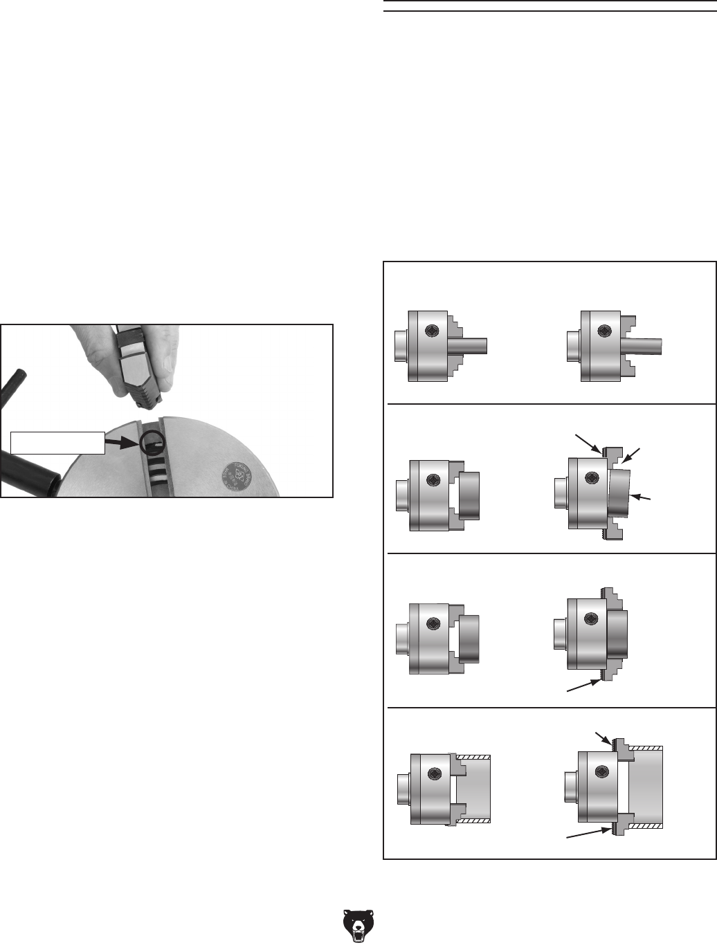
6. Rotate the chuck key clockwise until you see
the tip of the scroll-gear lead thread just begin
to enter a jaw guide (see Figure 28).
9. Install the remaining jaws in numerical order,
in the same manner.
— If installed correctly, the jaws will converge
evenly at the center of the chuck.
— If the jaws do not converge evenly, remove
them. Re-install the jaws sequentially 1–3,
and make sure each one engages with the
scroll-gear lead thread during its first rota-
tion.
To change the jaw set:
1. DISCONNECT LATHE FROM POWER!
2. Place a piece of plywood over the bedways to
protect them from potential damage.
3. Insert the chuck key and turn it counterclock-
wise to back the jaws out and remove them.
Figure 28. Lead thread on scroll gear.
Lead Thread
7. Insert jaw #1 into the jaw guide and hold the
jaw against the scroll-gear.
8. Rotate the chuck key clockwise one turn to
engage the tip of the scroll-gear lead thread
into the jaw. Pull the jaw; it should be locked
into the jaw guide.
The 3-jaw scroll-type chuck has an internal
scroll-gear
that moves all jaws in unison when
a
djusted with the chuck key. The chuck will hold
cylindrical parts on-center with the axis of spindle
rotation and can be
rotated at high speeds if the
workpiece is properly clamped and balanced.
Never mix jaw types or
positions to
accommodate an odd-shaped workpiece.
The
chuck will spin out of balance an
d may throw
the workpiece
! Instead, use an independent jaw
chuck or a faceplate.
Insufficient
Jaw Clamping Unstable
Workpiece
Bar Stock
Cylinder
Unsafe Jaw Position
Poor Scroll
Gear Engagement
Safer Inside
Jaw Use
Unsafe Inside
Jaw Use
Unsafe Jaw
Position
Safer Outside
Jaw Use
Poor Scroll Gear Engagement
Unsafe Jaw Position and
Poor Scroll
Gear
Engagement
Poor Grip
Unstable
Workpiece
Shallow
Bar Stock
Shallow
Bar Stock
Safer Outside
Jaw Use
Safer Inside
Jaw Use
CORRECT
CORRECT
CORRECT
CORRECT
INCORRECT
INCORRECT
INCORRECT
INCORRECT
Scroll Chuck
Clamping
Figure 29. Jaw selection and workpiece holding.

-30- Model G0602/G0752 (Mfg. Since 11/12)
Refer to the Chuck Installation (see Page 27)
and Chuck Removal (see Page 28) instructions
to install or remove the 4-jaw chuck.
The 4-jaw chuck features independently adjust-
able hardened steel jaws for holding non-con-
centric or off-center workpieces. Each jaw can
be independently removed from the chuck body
and reversed for a wide range of work holding
versatility.
To mount the workpiece:
1. DISCONNECT LATHE FROM POWER!
2. Place a chuck cradle or plywood on the
bedway below the chuck to protect the
bedway surfaces.
3. Use the chuck key to open each jaw so the
workpiece will lay flat against the chuck face,
jaw steps, or into the spindle opening.
4. With help from another person or a holding
device, position the workpiece so it is cen-
tered in the chuck.
Because of the dynamic forces involved in
machining a non-concentric or off-center
workpiece, always use a low spindle speed
to reduce risk of the workpiece coming loose
and being thrown from the lathe, which could
cause death or serious personal injury.
4-Jaw Chuck
Figure 30. 4-jaw tightening sequence.
1
2
3
4
Workpiece
Center Point
5. Tighten each jaw in small increments. After
you have adjusted the first jaw, continue
tightening the remaining jaws in an opposing
sequence, as shown by the sequential order
in Figure 30.
6. After the workpiece is held in place by the
jaws, use a dial indicator to make sure the
workpiece is centered in the chuck.
— If the workpiece is not correctly centered,
make fine adjustments by slightly loosen-
ing one jaw and tightening the opposing
jaw until the workpiece is correctly posi-
tioned (see Figure 31 for an example).
Figure 31. Generic picture of non-cylindrical
workpiece correctly mounted on the 4-jaw chuck.
Tools Needed: Qty
4-Jaw Chuck Key .............................................. 1
Dial Indicator ..................................................... 1
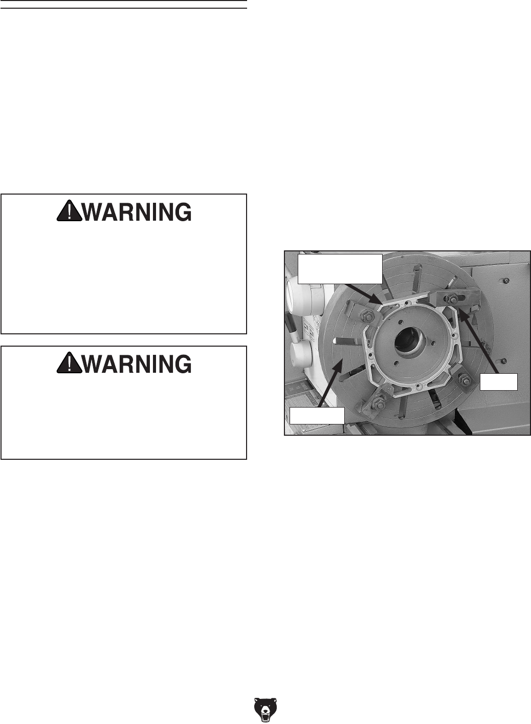
Model G0602/G0752 (Mfg. Since 11/12) -31-
Faceplate
Refer to the Chuck Installation (see Page 27)
and Chuck Removal (see Page 28) instructions
to install or remove the faceplate.
The faceplate included with your lathe can be
used for a wide range of operations, including
machining non-concentric workpieces, straight
turning between centers, off-center turning, and
boring.
The tools needed for mounting a workpiece will
vary depending on the type of setup you have.
Machining non-concentric workpieces at a
high speed could cause the workpiece to be
thrown from the spindle with deadly force
at the operator or bystanders. To reduce
this risk, only machine non-concentric
workpieces at low speeds and clamp
counter-weights to the faceplate to balance
it.
Failure to properly secure a workpiece to
the faceplate could cause the workpiece to
be thrown from the lathe with deadly force at
the operator or bystanders. Use a minimum
of THREE independent clamping devices to
hold the workpiece onto the faceplate.
To mount a non-concentric workpiece to the
faceplate:
1. DISCONNECT LATHE FROM POWER!
2. Protect the bedway with a piece of plywood.
3. With help from another person or a holding
device to support the workpiece, position it
onto the faceplate and clamp it in place with
a minimum of three independent clamping
devices (see Figure 32 for an example).
Be sure to take into account the rotational
and cutting forces that will be applied to the
workpiece when clamping it to the faceplate.
If necessary, use counter-weights to balance
the assembly and use a dial indicator to make
sure that the workpiece is properly positioned
for your operation.
Figure 32. Generic picture of workpiece clamped
in a faceplate.
Faceplate
Non-Cylindrical
Workpiece
Clamp

-32- Model G0602/G0752 (Mfg. Since 11/12)
The tailstock (see Figure 33) is typically used to
support long workpieces by means of a live or
dead center (refer to Centers on Page 36). It can
also be used to hold a drill or chuck to bore holes
in the center of a part. Custom arbors and tapers
can also be cut on your lathe by using the offset
tailstock adjustment.
Tailstock
Figure 33. Tailstock and quill lock handles in
locked position.
Tailstock
Lock Nut
Quill Lock
Lever
Quill Handwheel
Graduated Dial
Increments ................................................. 0.001"
One Full Revolution ................................... 0.060"
Increments on Quill
Inch ..............................0"-2
1⁄2" in 1⁄8" Increments
Metric ..................... 0–65mm in 1mm Increments
Positioning Tailstock
1. Loosen the tailstock lock nut to unlock the
tailstock from the bedway.
2. Slide the tailstock to the desired position.
3. Tighten the tailstock lock nut to lock the
tailstock against the bedway.
Using Quill
1. Loosen the quill lock lever.
2. Turn the quill handwheel clockwise to move
the quill toward the spindle or counterclock-
wise to move it away from it.
3. Tighten the quill lock lever.
Installing Tooling
This tailstock uses a quill with an MT#3 taper that
accepts a variety of tapered arbors and tooling,
including tang arbors and drill bits (see Figures
34–35 for examples).
Figure 34. Types of tapered arbors and tooling.
Solid
End
Open
End
Solid
End
Screw
End
Tang
Figure 35. Example photos of inserting MT#3
tools with tangs into a typical tailstock.
Tang
Note: If the tooling has an open hole in the end,
then a screw can be threaded into the end of the
tool to provide a solid surface for the quill pin to
push against when the quill is retracted for tool
removal. Otherwise, removal of such tooling may
be difficult.
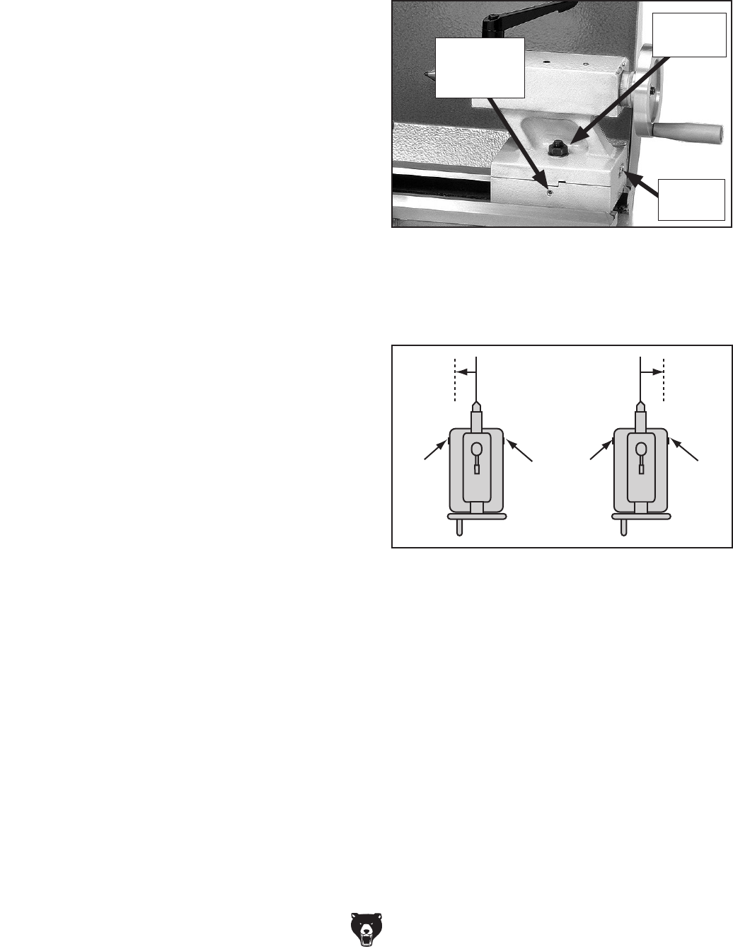
Model G0602/G0752 (Mfg. Since 11/12) -33-
To install tooling in the tailstock:
1. With the tailstock locked in place, unlock the
quill, then use the handwheel to extend it
approximately 1".
2. Thoroughly clean and dry the tapered mating
surfaces of the quill and the center, making
sure that no lint or oil remains on the tapers.
Removing Tooling
1. Use a shop rag to hold the tool.
2. Rotate the quill handwheel counterclockwise
until the tool is forced out of the quill.
Offsetting Tailstock
The tailstock can be offset from the spindle cen-
terline for turning tapers. Move the tailstock top
casting toward the front of the lathe to machine a
taper at the tailstock end. Conversely, position the
tailstock top casting toward the back of the lathe
to machine a taper at the spindle end.
Note: The marks on the offset indicator are arbi-
trary. For a precise offset, use a dial indicator to
check quill movement while adjusting the screws.
Tools Needed Qty
Hex Wrench 4mm .............................................. 1
Open-End Wrench 19mm .................................. 1
3. With a firm and quick motion, insert the tool
into the quill, as shown in Figure 35 on Page
32. Check to see if it is firmly seated by
attempting to twist it—a firmly seated tool will
not twist.
4. Unlock the tailstock and move it until the tip
of the tool is close to, but not touching, the
workpiece, then re-lock the tailstock.
5. Start spindle rotation, unlock the quill lock
lever, then turn the quill handwheel clockwise
to feed the tool into the workpiece.
To offset the tailstock:
1. Loosen the tailstock lock nut (see Figure 36).
2. Rotate the adjustment set screws in opposite
directions for the desired offset (see the illus-
tration in Figure 37).
Turn
CCW
Turn
CCW
Turn
CW
Turn
CW
Figure 37. Set screw adjustment in relation to
tailstock movement.
3. Retighten the tailstock lock nut to secure the
offset.
Figure 36. Left offset adjustment.
Tailstock
Lock Nut
Adjustment
Set Screw
(1 of 2)
Offset
Indicator
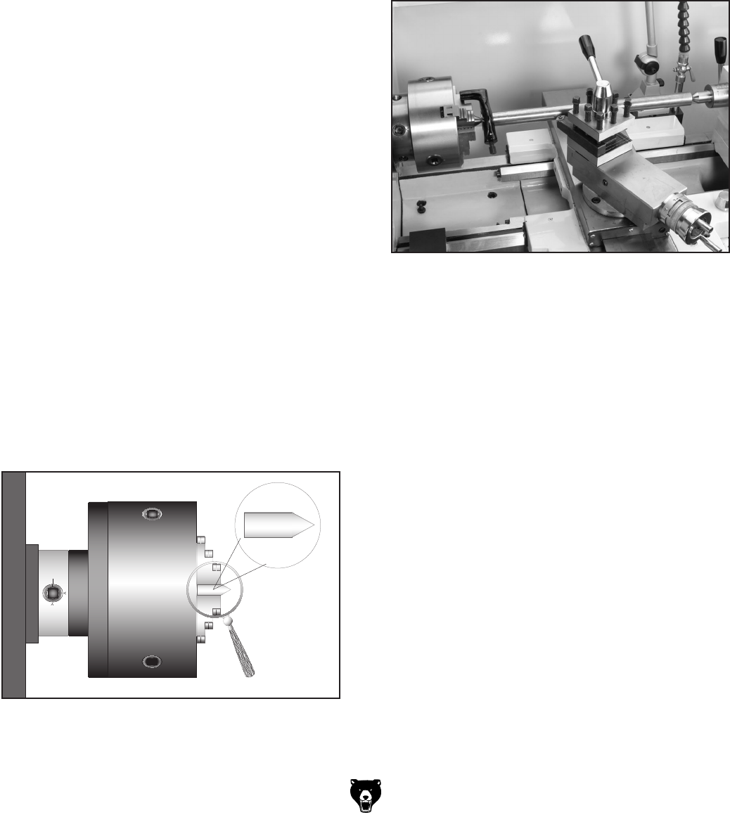
-34- Model G0602/G0752 (Mfg. Since 11/12)
This is an essential adjustment that should be ver-
ified or performed each time the tailstock is used
to turn concentric workpieces between centers
or immediately after offsetting the tailstock when
turning a taper. If the tailstock is not aligned with
the spindle centerline when it is supposed to be,
turning results will be inaccurate along the length
of the workpiece.
Items Needed Qty
Hex Wrench 4mm .............................................. 1
Open-End Wrench 19mm .................................. 1
Round Stock 2" x 6" .......................................... 2
Precision Level .................................................. 1
Precision Calipers ............................................. 1
Dial Indicator ..................................................... 1
To align the tailstock to the spindle center-
line:
1. Use the precision level to make sure the
bedway is level from side-to-side and from
front-to-back.
— If the bedway is not level, correct this con-
dition before continuing (refer to Leveling
& Mounting on Page 21).
2. Center drill both ends of one piece of round
stock, then set it aside for use in Step 5.
3. Use the other piece of round stock to make
a dead center, and turn it to a 60° point, as
illustrated in Figure 38.
Figure 38. Turning a dead center.
Aligning Tailstock to Spindle
Centerline
Note: As long as this dead center remains in
the chuck, the point of the center will remain
true to the spindle centerline. The point will
have to be refinished whenever the center is
removed and then returned to the chuck.
4. Install a center in the tailstock.
5. Attach a lathe dog to the test stock from Step
2, then mount it between the centers (see
Figure 39 for an example).
Figure 39. Example photo of stock mounted
between the centers.
6. Turn 0.010" off the stock diameter.
7. Mount a test or dial indicator so that the
plunger is on the tailstock quill.
Note: If necessary in the following step,
refer to Offsetting Tailstock on Page 33 for
detailed instructions.
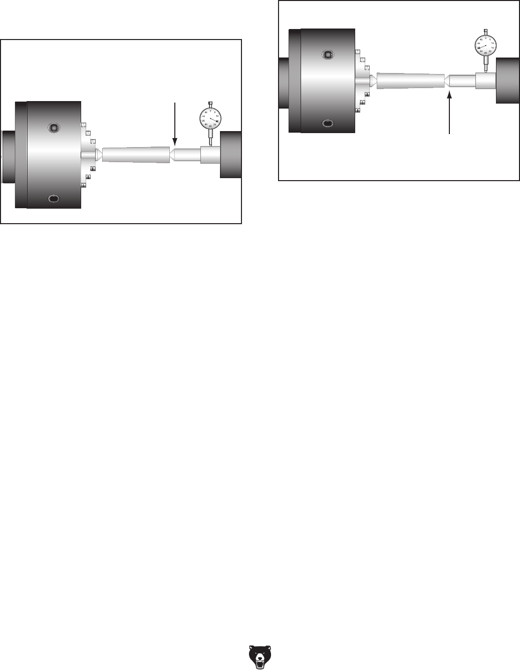
Model G0602/G0752 (Mfg. Since 11/12) -35-
8. Use calipers to measure both ends of the
workpiece.
— If the test stock is thicker at the tailstock
end, move the tailstock toward the front of
the lathe 1⁄2 the distance of the amount of
taper (see Figure 40).
9. Repeat Steps 6–8 until the desired accuracy
is achieved.
Move the tailstock toward
the front of the machine half
the distance of the taper
Looking down from above
Figure 40. Adjust tailstock toward the operator.
— If the test stock is thinner at the tailstock
end, move the tailstock toward the back of
the lathe 1⁄2 the distance of the amount of
taper (see Figure 41).
Move tailstock toward the
back of the machine half
the distance of the taper
Looking down from above
Figure 41. Adjust tailstock away from the
operator.
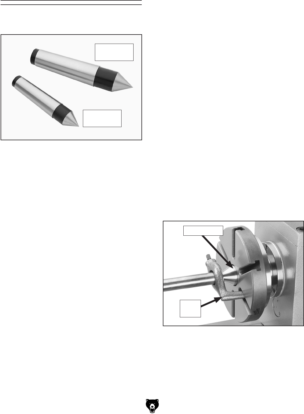
-36- Model G0602/G0752 (Mfg. Since 11/12)
Figure 42 shows one of the two included MT#3
dead centers and the MT#4 dead center.
Centers
Figure 42. Dead centers.
MT#3 Dead
Center
MT#4 Dead
Center
Dead Centers
A dead center is a one-piece center that does not
rotate with the workpiece and is used to support
long, slender workpieces in the tailstock.
A carbide-tipped dead center (not included) can
better withstand the effects of friction than a typi-
cal dead center and is best used in the tailstock
where the workpiece will rotate against it. The tip
of a dead center must be generously lubricated
during the operation to avoid premature wear and
maximize smooth operation. Using low spindle
speeds will also reduce the heat and wear from
friction.
Use the dead center in the spindle for operations
where the workpiece rotates with the center and
does not generate friction.
The spindle taper is an MT#4 and will only receive
the MT#4 dead center. The tailstock quill taper
is an MT#3 and will only receive the MT#3 dead
centers.
Live Centers
A live center (not included) has bearings that
allow the center tip and the workpiece to rotate
together; it can be installed in the tailstock quill for
higher speeds.
Mounting Dead Center in Spindle
1. DISCONNECT LATHE FROM POWER!
2. Thoroughly clean and dry all threads and
mating surfaces of the spindle bore and the
center, making sure that no lint or oil remains
on these surfaces.
Note: This will prevent the tapered surfaces
from seizing due to operational pressures,
which could make it very difficult to remove
the center.
3. Mount a chuck or faceplate onto the spindle,
whichever is correct for your operation.
4. Insert the center into the spindle bore through
the chuck or faceplate.
Figure 43 shows an example photo of a dead
center installed in the spindle, using a lathe
dog and faceplate for turning between cen-
ters.
Figure 43. Example photo of using a dead
center with a faceplate and lathe dog.
Dead Center
Lathe
Dog
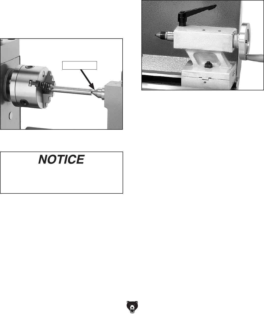
Model G0602/G0752 (Mfg. Since 11/12) -37-
Removing Center from Spindle
To remove the center from the spindle, insert a
piece of round bar stock or similar tool through the
outboard end (on the left side of the headstock).
Have another person hold onto the center with
a gloved hand or shop rag, then tap the center
loose.
To mount a center in the tailstock:
1. DISCONNECT LATHE FROM POWER!
2. Thoroughly clean and dry the tapered mating
surfaces of the tailstock quill bore and the
center, making sure that no lint or oil remains
on the tapers.
Mounting Center in Tailstock
The included dead center or a live center can be
used in the tailstock. Mounting instructions are
the same for both. Figure 44 shows an example
photo of a dead center mounted in a tailstock.
Figure 44. Example photo of using a dead
center installed in the tailstock.
To avoid premature wear of the dead center
or damage to the workpiece, use low spindle
speeds and keep the tip of the dead center
mounted in the tailstock well lubricated.
3. Use the quill handwheel to feed the quill out
of the casting approximately 1" (see Figure
1).
Note: The maximum quill travel is 21⁄2", but
we do not recommend extending the quill
more than 2" or stability and accuracy will be
reduced.
Figure 1. Dead center inserted into tailstock.
4. Insert the center into the tailstock quill.
5. Seat the center firmly into the quill during
workpiece installation by rotating the quill
handwheel clockwise to apply pressure, with
the center engaged in the center hole in the
workpiece.
Note: Only apply enough pressure with the
tailstock quill to securely mount the workpiece
between centers. Avoid overtightening the
center against the workpiece, or it may
become difficult to remove later, and it will
result in excessive friction and heat, which
may damage the workpiece and center.
6. Secure the quill lock lever and tailstock lock
nut.
Removing Center from Tailstock
To remove the center from the quill, hold onto it
with a gloved hand or shop rag, then rotate the
quill handwheel counterclockwise to draw the quill
back into the casting until the center releases.
Dead Center
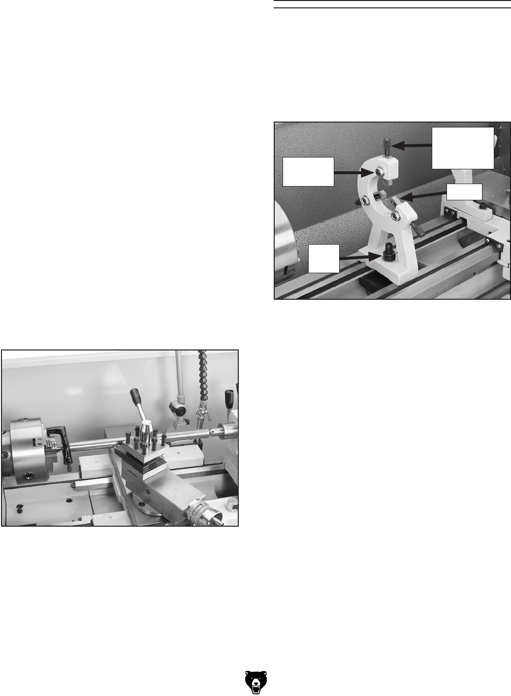
-38- Model G0602/G0752 (Mfg. Since 11/12)
Mounting Workpiece Between
Centers
1. DISCONNECT LATHE FROM POWER!
2. Drill center holes in both ends of the workpiece.
3. Install a dead center in the spindle with a
lathe dog and a chuck or faceplate, then
install a live center or carbide-tipped dead
center in the tailstock.
4. Lubricate the workpiece center holes, then
mount the workpiece between the centers
and hold it in place with light pressure from
the tailstock center.
5. Seat the center firmly into the quill by rotating
the quill handwheel clockwise to apply pres-
sure against the workpiece (see the example
in Figure 45).
Note: Only apply enough pressure to secure-
ly mount the workpiece between centers.
Avoid over-tightening the center against the
workpiece, or it may become difficult to
remove later. Also, over-tightening will result
in excessive friction and heat, which may
damage the workpiece or center.
The steady rest supports long shafts and can
be mounted anywhere along the length of the
bedway.
Familiarize yourself with the steady rest compo-
nents shown in Figure 46 to better understand its
operation.
To install and use the steady rest:
1. DISCONNECT LATHE FROM POWER!
2. Thoroughly clean all mating surfaces, then
place the steady rest base on the bedways
so the triangular notch fits over the bedway
prism.
3. Loosen the finger lock nuts shown in
Figure 46, turn the finger adjustment knobs,
and adjust the fingers as required for the
workpiece.
4. Loosen the steady rest lock nut, position the
steady rest where required to properly sup-
port the workpiece, then secure the lock nut.
5. Turn the finger adjustment knobs so the fin-
gers are barely touching the workpiece, then
tighten the finger lock nuts.
6. Lubricate the finger tips with an anti-seize
lubricant during operation.
Note: Mill or file the tips if they show wear.
Figure 46. Steady rest components.
Steady Rest
Finger
Lock
Nut
Figure 45. Example photo of a workpiece
mounted between the centers.
6. Secure the quill lock lever and tailstock lock
nut.
Finger
Adjustment
Knob
Finger
Lock Nut
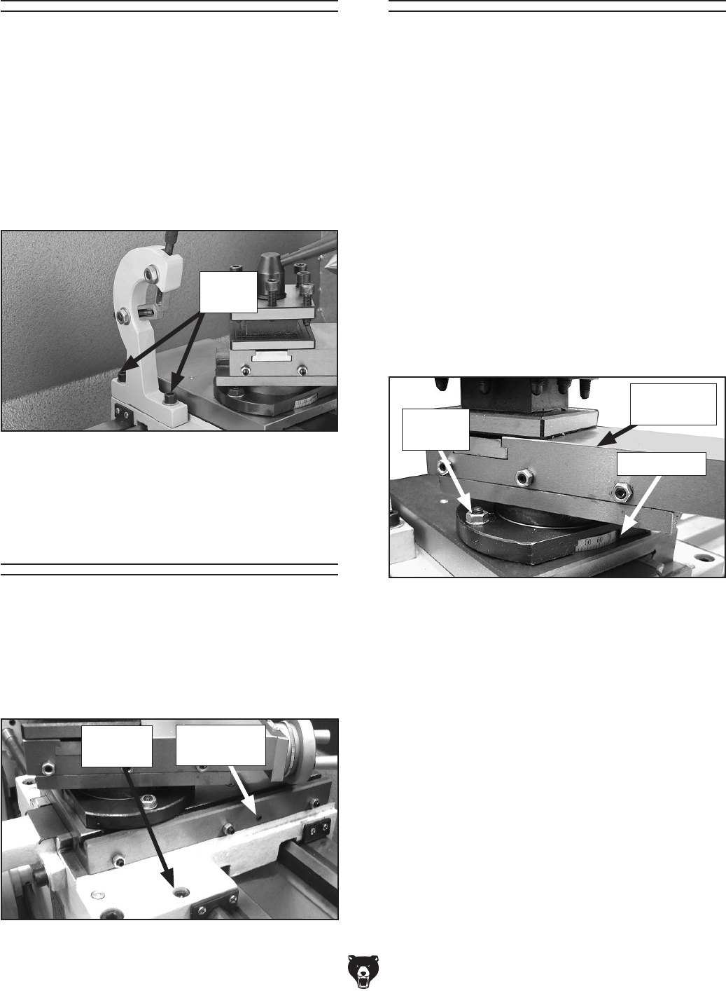
Model G0602/G0752 (Mfg. Since 11/12) -39-
The follow rest mounts to the saddle with two cap
screws (see Figure 47). It is used on long, slender
parts to prevent workpiece deflection from cutting
tool pressure during operation. Adjust the follow
rest fingers in the same manner as the those on
the steady rest.
Note: To reduce the effects of friction, lubricate
the finger tips with generous anti-sieze lubricant
during operation.
Figure 47. Follow rest attachment.
Cap
Screws
Follow Rest
The carriage and cross slide have locks that can
be tightened to provide additional rigidity during
operation, especially during heavy cuts.
See Figure 48 to identify the locations of the
locks for each device.
Carriage & Slide
Locks
Figure 48. Carriage and cross slide locks.
Cross Slide
Lock
Carriage
Lock
The compound rest handwheel has an indirect-
read graduated scale. This means the distance
shown on the scale represents the actual distance
the tool moves. The base of the compound rest
has another graduated scale used for setting the
cutting tool to a specific angle.
Graduated Dial
Increments ............................... 0.001" (0.025mm)
One Full Revolution ..................... 0.04" (1.02mm)
Tool Needed Qty
Open-End Wrench 14mm .................................. 1
To set the compound rest at a certain angle:
1. Loosen the two hex nuts at the base of the
compound rest (1 of 2 shown in Figure 49).
Compound Rest
2. Rotate the rest to the desired angle, as
indicated by the scale at the base,
then retighten the two hex nuts.
Tip: The first time you set the angle of the
compound rest for cutting threads, mark the
location on the cross slide as a quick refer-
ence point. This will allow you to quickly
return the compound rest to that exact angle
the next time you need to cut threads.
Figure 49. Compound rest.
Compound
Rest
Angle Scale
Hex Nut
(1 of 2)
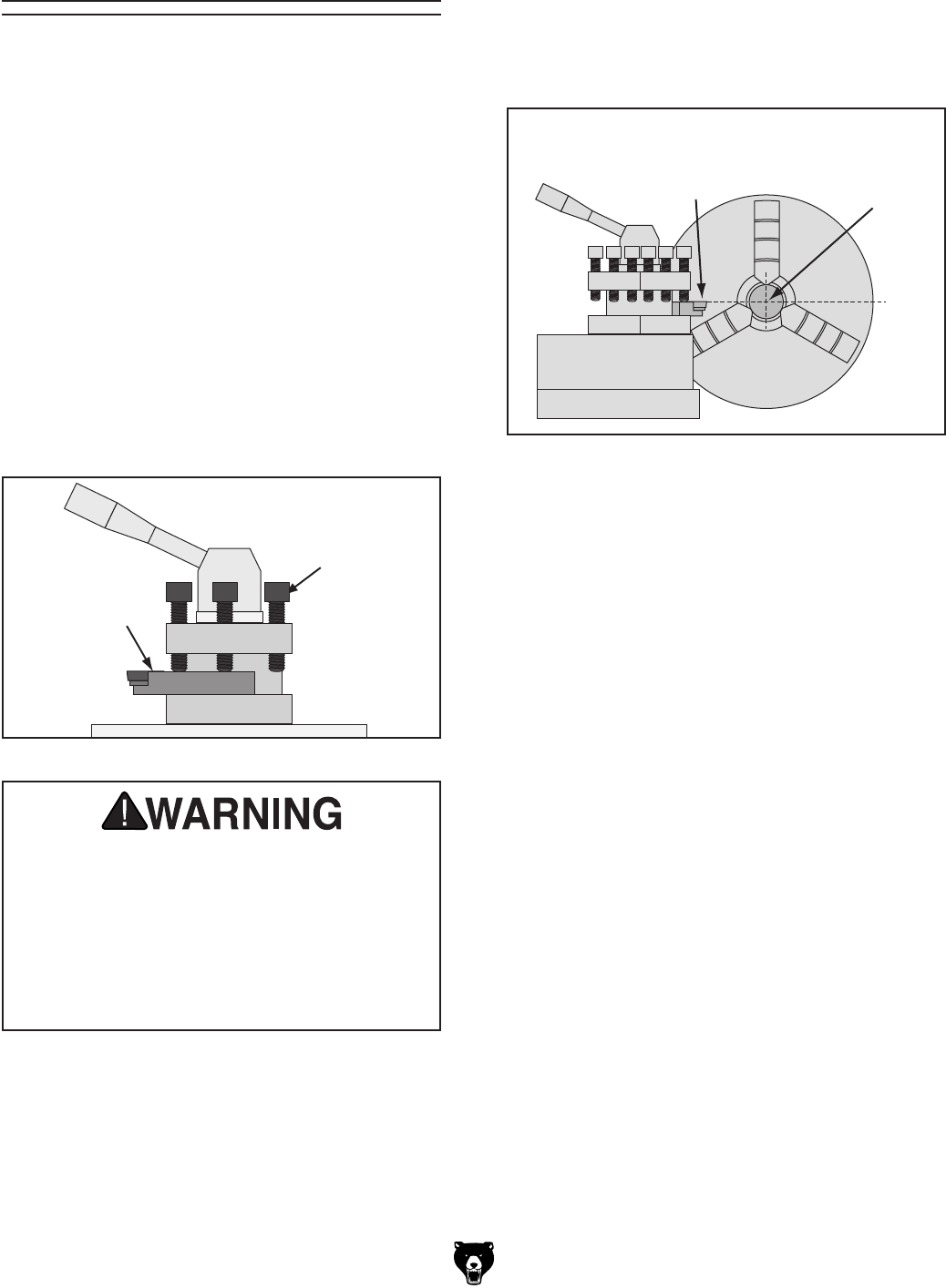
-40- Model G0602/G0752 (Mfg. Since 11/12)
The four-way tool post is mounted on top of the
compound rest and allows a maximum of four 1⁄2"
tools to be loaded simultaneously.
Each tool can be quickly indexed to the workpiece
by loosening the top handle, rotating the tool post
to the desired position, then re-tightening the
handle to lock the tool into position.
Four-Way Tool Post
Tool Needed Qty
Hex Wrench 6mm .............................................. 1
To install a tool in the tool post:
1. Adjust the tool post screws so that the cutting
tool can fit underneath them (see Figure 50).
Installing Tool
2. Firmly secure the cutting tool with at least two
tool post screws.
3. Check and adjust the cutting tool to the
spindle centerline, as instructed in the next
subsection.
Figure 50. Example of tool mounted in tool post.
Cutting
Tool
Tool Post
Screw
Over-extending a cutting tool from the post
will increase the risk of tool chatter, breakage,
or tool loosening during operation, which
could cause metal pieces to be thrown at
the operator or bystanders with great force.
DO NOT extend a cutting tool more than 2.5
times the width of its cross-section (e.g.,
2.5 x 0.5" = 1.25").
Aligning Cutting Tool with Spindle
Centerline
For most operations, the cutting tool tip should be
aligned with the spindle centerline, as illustrated
in Figure 51.
There are a number of ways to check and align
the cutting tool to the spindle centerline. If nec-
essary, you can raise the cutting tool by placing
steel shims underneath it. The shims should be
as long and as wide as the cutting tool to properly
support it.
Below are two common methods:
• Move the tailstock center over the cross slide
and use a dial indicator to measure the dis-
tance from the surface of the cross slide to
the tip of the center. Adjust the cutting tool
height so it is the same distance above the
cross slide as the tailstock center.
• Align the tip of the cutting tool with a tailstock
center, as instructed in the following pro-
cedure. For this to work, the tailstock must
be aligned to the spindle centerline (refer to
Aligning Tailstock To Spindle Centerline
on Page 34 for detailed instructions).
Cutting
Tool
Spindle
Center
Line
Figure 51. Cutting tool aligned with spindle
centerline (viewed from tailstock).
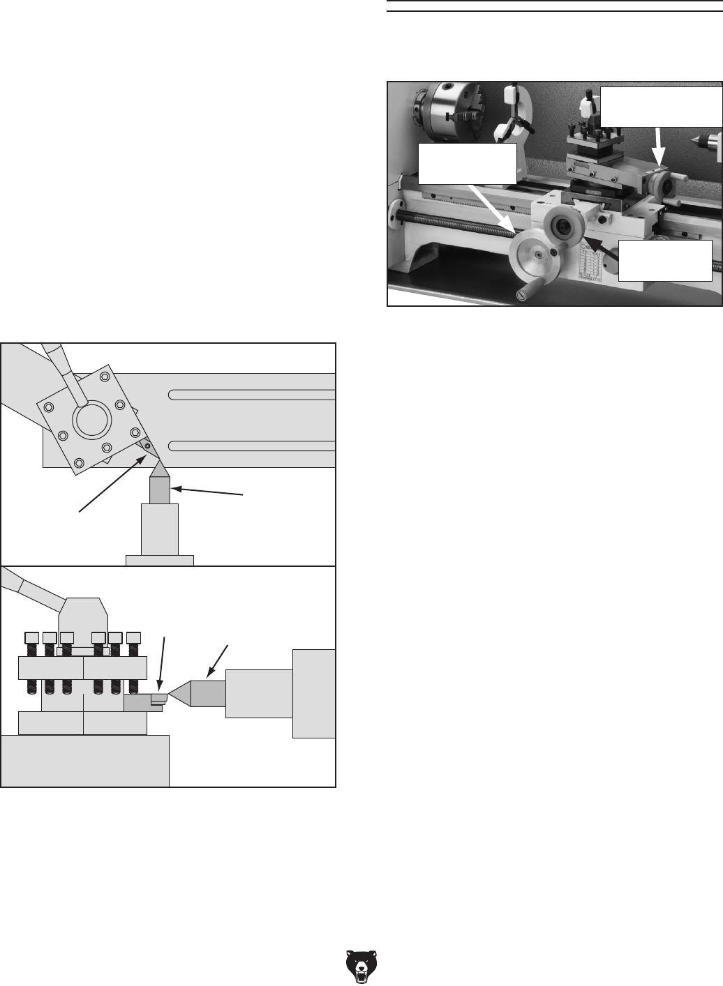
Model G0602/G0752 (Mfg. Since 11/12) - 41-
Tools Needed Qty
Hex Wrench 6mm .............................................. 1
Steel Shims ....................................... As Needed
Cutting Tool ....................................................... 1
Tailstock Center ................................................. 1
To align the cutting tool with the tailstock
center:
1. Mount the cutting tool in the tool post, then
secure the post so the tool faces the tailstock.
2. Install a center in the tailstock, and position
the center tip near the cutting tool tip.
3. Lock the tailstock and quill in place.
4. Adjust the height of the cutting tool so that the
tool tip is aligned vertically and horizontally
with the center tip, as shown in Figure 52.
Cutting
Tool Tailstock
Center
(Side View)
Figure 52. Cutting tool aligned to the tailstock
center.
Cutting
Tool
Tailstock
Center
(Top View)
Carriage Handwheel
Use the carriage handwheel to move the carriage
left or right along the bed. This control is help-
ful when setting up the machine for turning or
when manual movement is desired during turning
operations.
Cross Slide Handwheel
Graduated Dial
Increments ............................... 0.001" (0.025mm)
One Full Revolution ..................... 0.06" (1.52mm)
Use this handwheel to move the tool toward and
away from the work. Adjust the position of the
graduated scale by holding the handwheel with
one hand and turning the dial with the other.
The cross slide handwheel has an indirect-read
graduated dial. This means the distance shown
on the scale represents the actual distance the
tool moves.
Compound Rest Handwheel
Graduated Dial
Increments .............................. 0.001" (0.025mm)
One Full Revolution ..................... 0.04" (1.02mm)
Use this handwheel to move the cutting tool lin-
early along the set angle of the compound rest.
Set the compound rest angle by hand-rotating it
and securing in place with two hex nuts. The com-
pound rest has an indirect-read graduated dial.
The handwheels shown in Figure 53 allow the
operator to manually move the cutting tool.
Manual Feed
Figure 53. Manual handwheel controls.
Carriage
Handwheel
Cross Slide
Handwheel
Compound Rest
Handwheel
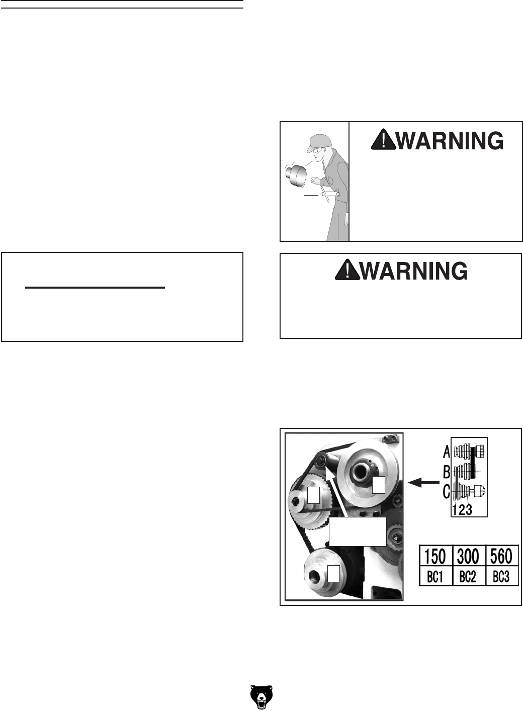
-42- Model G0602/G0752 (Mfg. Since 11/12)
Use a low RPM when machining
heavy eccentric workpieces;
securely clamp your workpiece
and remove the chuck key!
Objects thrown from a lathe can
cause serious injury or death to
the operator or bystanders.
Use a minimum of three independent clamping
devices when turning eccentric workpieces
on the faceplate. Failure to provide adequate
clamping will cause workpiece to eject.
Spindle Speed
Using the correct spindle speed is important for
safe and satisfactory results, as well as maximiz-
ing tool life.
To set the spindle speed for your operation, you
will need to: 1) Determine the best spindle speed
for the cutting task, and 2) configure the lathe
controls to produce the required spindle speed.
Determining Spindle Speed
Many variables affect the optimum spindle speed
to use for any given operation, but the two most
important are the recommended cutting speed
for the workpiece material and the diameter of
the workpiece, as noted in the formula shown in
Figure 54.
Cutting speed, typically defined in feet per minute
(FPM), is the speed at which the edge of a tool
moves across the material surface.
A recommended cutting speed is an ideal speed
for cutting a type of material in order to produce
the desired finish and optimize tool life.
The books Machinery’s Handbook or Machine
Shop Practice, and some internet sites, pro-
vide excellent recommendations for which cutting
speeds to use when calculating the spindle speed.
These sources also provide a wealth of additional
information about the variables that affect cutting
speed and they are a good educational resource.
Also, there are a large number of easy-to-use
spindle speed calculators that can be found on
the internet. These sources will help you take into
account the applicable variables in order to deter-
mine the best spindle speed for the operation.
Cutting Speed (FPM) x 12
*Recommended
Dia. of Cut (in inches) x 3.14
Spindle
Speed
(RPM)
*Double if using carbide cutting tool
=
Figure 54. Spindle speed formula for lathes.
Setting Spindle Speed
Selecting one of the available six spindle speeds
(Model G0602) or one of the three spindle speed
ranges (Model G0752) is performed by reposition-
ing the V-belt(s) between the pulleys.
Tools Needed Qty
Hex Wrench 5mm .............................................. 1
Hex Wrench 8mm .............................................. 1
Open-End Wrench 17mm .................................. 1
G0602 Configuration Examples
The 271⁄2" belt is used on pulleys B and C (see
Figure 55) with the tensioner for 50, 300, and
560 RPM.
Figure 55. Positioning belt for low speed.
Tensioner
Used
A
BC
Model G0602/G0752 (Mfg. Since 11/12) -43-
3. Open the change gear cover, then loosen the
tensioner lock nut located on the other side of
the gear cover plate and the headstock.
The 33" belt is used on pulleys A and C (see
Figure 56) without the tensioner for 720, 1200,
and 2400 RPM.
Figure 58. Location of tensioner lock nut.
4. Move the tensioner to install the 271⁄2" belt
between pulleys B and C, and in sheave 1,
as shown in Figure 55 on Page 42.
5. Re-tension the belt (refer to "Tensioning
V-Belt" on Page 63), then close the change
gear cover and secure it. The lathe is now set
for a spindle speed of 150 RPM.
Locking Nut
Figure 57. G0602 RPM chart.
RPM
Pulley
Combination
RPM Chart
To set the spindle speed to 150 RPM:
1. DISCONNECT LATHE FROM POWER!
2. Refer to the RPM chart in Figure 57 to deter-
mine the pulley combination you need to
achieve a spindle speed of 150 RPM—it is
BC1.
Follow along with the examples below for setting
the Model G0602 spindle speed to gain a better
understanding of this task.
Figure 56. Positioning belt for high speed.
Tensioner
Not Used
A
C
B
G0752 Configuration Example
The V-belt is positioned on the spindle and motor
pulleys with the tensioner (see Figure 59) to select
between low (100-800 RPM), medium (160-1300
RPM), and high (250–2000 RPM) speed ranges.
Figure 59. Positioning belt for low speed.
Tensioner
L M H
Motor
Pulley
Spindle
Pulley
Bolt

-44- Model G0602/G0752 (Mfg. Since 11/12)
The carriage has power feed capability when it
is engaged with the lead screw. The rate that the
carriage moves (feed rate) is controlled by V-belt,
change gear, and gearbox dial configurations.
Feed rate and spindle speed must be considered
together when determining the proper cutting
speed for a given workpiece. The sources you
use to determine the optimum spindle speed for
an operation will also provide the optimal feed rate
to use with that spindle speed.
Often, the experienced machinist will use the
feeds and speeds given in their reference charts
or web calculators as a starting point, then make
minor adjustments to the feed rate (and some-
times spindle speed) to achieve the best results.
The carriage can alternately be driven by the
leadscrew for threading operations. However, this
section only covers using the power feed option
for the carriage for non-threading operations. To
learn how to power the carriage for threading
operations, refer to Threading on Page 46.
Power Feed
Tools Needed Qty
Hex Wrench 5mm .............................................. 1
Hex Wrench 6mm .............................................. 1
Follow along with this example for setting the
spindle speed for the Model G0752 to gain a bet-
ter understanding of this task.
To set the spindle speed to 150 RPM:
1. DISCONNECT LATHE FROM POWER!
2. Open the change gear cover, use an 8mm
hex wrench to loosen the tensioner bolt, then
move the tensioner out of the way.
3. Move the V-belt to the outer pulley sheaves
to select the low speed range (100-800
RPM), as shown in Figure 59.
4. Re-tension the belt (refer to "Tensioning
V-Belt" on Page 63) and secure the tension-
er.
5. Turn the spindle direction switch to FWD, and
press the ON button.
6. Adjust the spindle speed dial until the spindle
speed display reads 150 RPM.
Model G0602/G0752 (Mfg. Since 11/12) -45-
The feed rate chart on the headstock displays the
settings for the feed controls for inch feed rates.
Using the controls on the lathe, follow along with
the example below to better understand how to
set the lathe for the desired power feed rate.
Setting Power Feed Rate of 0.0120 in/rev
1. DISCONNECT LATHE FROM POWER!
2. Turn the feed dials to the numeral and letter
indicated by the chart in Figure 61.
Note: You may have to rock the chuck by
hand to get the gearbox gears to mesh.
3. Gather the required change gears, based
upon the chart in Figure 61.
4. Remove the cap screw that secures the
change gear cover, open the cover, then
loosen the lash adjuster cap screw (see
Figure 61) and swing the change gear
assembly out of the way.
5. Remove the E-clips and cap screw from the
change gears.
6. Lubricate the change gears (refer to Page 55
for detailed instructions) and swap them out
in the order shown on the chart in Figure 61,
then re-install the E-clips and cap screw.
Setting Power Feed Rate
7. Move the lash adjuster so the gear backlash
is between 0.003" to 0.008", tighten the lash
adjuster cap screw, then close and secure
the change gear cover.
8. Loosen the carriage lock (see Figure 60),
and push down on the half nut lever to
engage the power feed.
Figure 60. Carriage lock and feed control.
Carriage Lock
Cap Screw
Half Nut
Lever
The lathe is now set up for a power feed rate of
0.0120 in/rev.
To avoid potential carriage/chuck crash,
disengage the half-nut lever immediately
after completing power feeding operations.
Note: All change gears are stamped with the
number of teeth they have.
Figure 61. Power feed setup.
= 0.012" Feed
Feed Dials
Feed Chart
Change Gears
E-Clips
Cap
Screw
Lash Adjuster Cap Screw
104
127
56
27 60
40
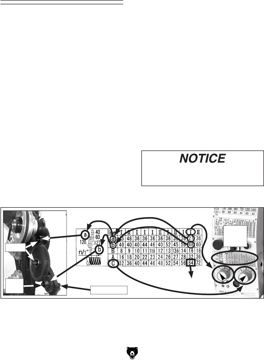
-46- Model G0602/G0752 (Mfg. Since 11/12)
The following subsections describe how to use
the threading controls and charts to set up the
lathe for a threading operation. If you are unfamil-
iar with the process of cutting threads on a lathe,
we strongly recommend that you read books,
review industry trade magazines, or get formal
training before attempting any threading projects.
Headstock Threading Controls
The threading charts on the headstock face dis-
play the settings for metric and inch threading.
Using the controls on the lathe, complete the fol-
lowing examples to better understand how to set
up the lathe for the desired threading operation.
Threading 4. Open the change gear cover, loosen the lash
adjuster (Figure 61 on Page 45) and swing
the change gear assembly out of the way.
5. Remove the E-clips and cap screw from the
change gears.
6. Lubricate the change gears (refer to Page 55
for detailed instructions) and swap them out
in the order shown on the chart in Figure 62,
then secure the change gears with the E-clips
and cap screw.
Note: All change gears are stamped with the
number of teeth they have.
7. Move the lash adjuster so the gear backlash
is between 0.003" to 0.008", tighten the lash
adjuster cap screw, and close the cover.
8. Loosen the carriage lock (see Figure 60 on
Page 45).
The lathe is now set up to cut 64 TPI threads.
When threading keep your hand on the half-
nut lever ready to disengage the half nut to
avoid potential carriage/chuck crash.
To set the lathe to cut 64 TPI threads:
1. DISCONNECT LATHE FROM POWER!
2. Turn the feed dials to the numeral and letter
indicated by the chart in Figure 62.
Note: You may have to rock the chuck by
hand to mesh the gearbox gears.
3. Gather the required change gears based
upon the chart.
Figure 62. Threading setup for 64 TPI.
= 64 TPI
Lash Adjuster
E-Clips
Inch
Thread
Chart
Cap
Screw
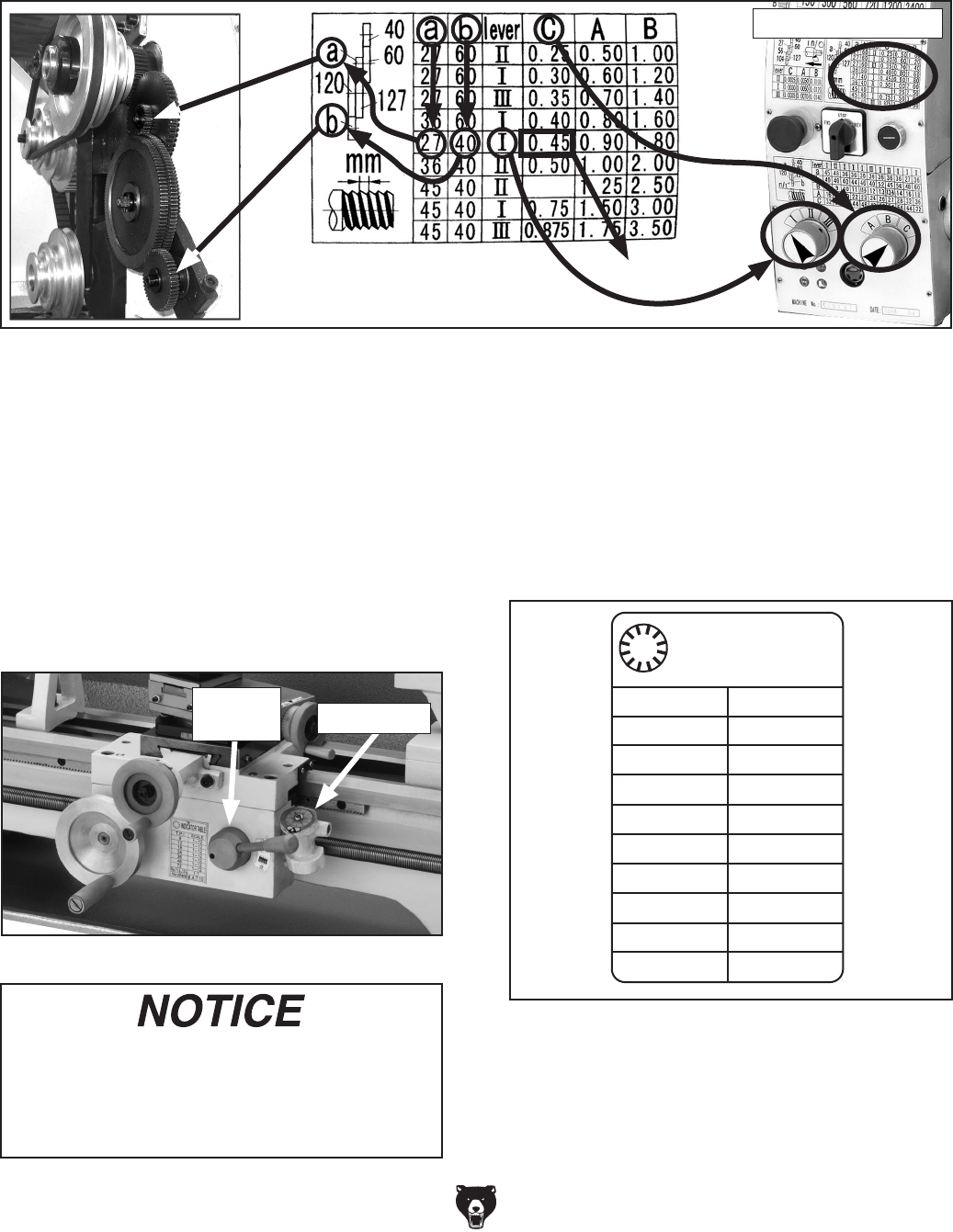
Model G0602/G0752 (Mfg. Since 11/12) -47-
To set the lathe to cut 0.45 TPmm threads:
The steps for setting up the lathe for threading metric threads are the same as those for inch threads. Follow
the instructions on Page 46 for setting the thread pitch to 64 TPI, and refer to the chart below.
Note: Since this lathe has an inch leadscrew,
do not use the thread dial when cutting metric
threads. Instead you must leave the half nut
engaged from the beginning until the threading
operation is complete.
Apron Threading Controls
The half nut lever engages the carriage with the
leadscrew, which moves the carriage and cutting
tool along the length of the workpiece for thread-
ing and power feed operations (see Figure 64).
The numbers on the thread dial are used with the
thread dial chart to show when to engage the half
nut during inch threading. The thread dial num-
bers are not used when cutting metric threads,
since this lathe has an inch leadscrew.
When threading, we recommend using the
slowest speed possible and avoiding deep
cuts, so you are able to disengage the half
nut when required and prevent an apron
crash!
Figure 64. Half nut lever and thread dial.
Thread Dial
Half Nut
Lever
Thread Dial Chart
Find the TPI (threads per inch) that you want
to cut in the left column of the thread dial chart
(see Figure 65), then reference the dial number
to the right of it. The dial numbers indicate when
to engage the half nut for a specific thread pitch.
The thread dial chart can also be found on the
carriage beside the half nut lever.
Indicator Table
9
TPI SCALE
12
18
24
36
48
72
9½,11½, ,13½
1-12
1-12
1-12
1-12
1-12
1-12
1-12
1.7
1.4.7.10
Other TPI
Figure 65. Thread dial chart.
Figure 63. Metric threading setup.
= 0.45 TPmm
Metric Thread Chart
-48- Model G0602/G0752 (Mfg. Since 11/12)
The following examples explain how to use the
thread dial chart.
9, 12, 18, 24, 36, 48, 72 TPI
For these threading TPI's, use any of the lines on
the thread dial (see Figure 66).
All Other TPI
For all other TPI's, use numbered lines 1 or 7 or
non-numbered lines 4 or 10 on the thread dial
(see Figure 68).
All Other TPI
POSITION
1,4, 7, 10
TPI
91/2 ,111/2 ,131/2
POSITION
1,7
TPI
ANY
POSITION
9, 12, 18, 24, 36, 48, 72
TPI
5
7
3
1
11
9
5
7
3
1
11
9
5
7
3
1
11
9
Figure 66. 9, 12, 18, 24, 36, 48, 72 TPIs.
91⁄2, 111⁄2 ,131⁄2 Fractional TPI
For threading these TPIs, use the numbered lines
1 or 7 on the thread dial (see Figure 67).
All Other TPI
POSITION
1,4, 7, 10
TPI
91/2 ,111/2 ,131/2
POSITION
1,7
TPI
ANY
POSITION
9, 12, 18, 24, 36, 48, 72
TPI
5
7
3
1
11
9
5
7
3
1
11
9
5
7
3
1
11
9
Figure 67. 91⁄2, 111⁄2 131⁄2 TPIs.
All Other TPI
POSITION
1,4, 7, 10
TPI
91/2 ,111/2 ,131/2
POSITION
1,7
TPI
ANY
POSITION
9, 12, 18, 24, 36, 48, 72
TPI
5
7
3
1
11
9
5
7
3
1
11
9
5
7
3
1
11
9
Figure 68. All other TPIs.
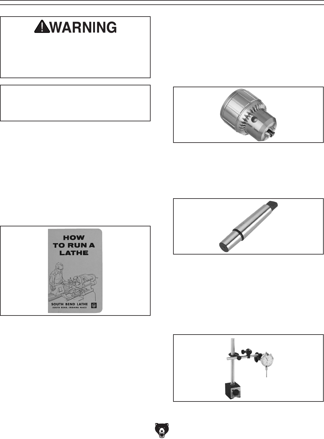
Model G0602/G0752 (Mfg. Since 11/12) -49-
SECTION 5: ACCESSORIES
Installing unapproved accessories may
cause machine to malfunction, resulting in
serious personal injury or machine damage.
To reduce this risk, only install accessories
recommended for this machine by Grizzly.
NOTICE
Refer to our website or latest catalog for
additional recommended accessories.
Figure 70. H6204 Drill Chuck.
H6204—High Precision Drill Chuck 5/8" x JT3
Unlike most keyed drill chucks, this one is made
to very tight tolerances on CNC equipment and is
one of the finest drill chucks on the market today.
It has very high gripping strength and is suitable
for heavy-duty, high-speed drilling. Each chuck
includes a high visibility chuck key. Specifications:
1⁄32"- 5⁄8" x JT #3.
Figure 72. G9849 Magnetic Base/Dial Indicator.
G9849—Magnetic Base/Dial Indicator Combo
Precision measurements and set-ups have never
been so easy. Magnetic base engages with just
the turn of a switch and allows pinpoint adjust-
ment. The dial indicator features 0–1" travel and
has a resolution of 0.001". Set includes a molded
case for protection and convenience.
Figure 71. G1677 Drill Chuck Arbor.
G1677—Drill Chuck Arbor - MT3/JT3
This Drill Chuck Arbor is used to adapt drill chucks
to your drill press, milling machine or lathe. Long
end: MT #3, Short end: J.T. #3.
SBCE3450—How to Run a Lathe
First printed in 1907 by South Bend Lathe, this
56th edition is an exact reprint from 1966. Well
illustrated with vintage photos and drawings, this
128-page book is written specifically about the
care and operation of a metal lathe. “This book is
to aid the beginner or apprentice in the machine
shop and the student in the school shop to secure
a better understanding of the fundamental opera-
tions of modern lathe practice in use in modern
industries in the United States.”
Figure 69. SBCE3450 South Bend Lathe~How
to Run a Lathe book.
H2987—½" Bent Lathe Dog
H2988—1" Bent Lathe Dog
H2989—1½" Bent Lathe Dog
H2990—2" Bent Lathe Dog
H2991—3" Bent Lathe Dog
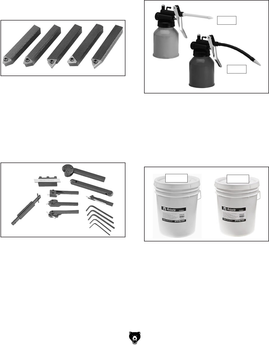
-50- Model G0602/G0752 (Mfg. Since 11/12)
T10255—Mini Lathe Tooling Kit
This convenient Mini Lathe Tool Kit includes right,
left and straight turning tool holders with 1⁄8" HSS
tool bits, boring bar with holder and 1⁄8" HSS tool
bit, cut off tool holder with 3⁄32" HSS blade and
3⁄8" shank, mini cut off tool holder with 1⁄16" HSS
blade and 5⁄16" shank, knurling tool holder with
pivoting head, single horizontal/vertical knurling
tool holder and assorted hex wrenches. Maximum
shank size is 1⁄2".
Figure 74. T10255 Mini Lathe Tooling Kit.
T23962—ISO 68 Moly-D Machine Oil, 5 gal.
T23963—ISO 32 Moly-D Machine Oil, 5 gal.
Moly-D oils are some of the best we've found for
maintaining the critical components of machinery
because they tend to resist run-off and maintain
their lubricity under a variety of conditions—as
well as reduce chatter or slip. Buy in bulk and
save with 5-gallon quantities.
Figure 76. ISO 68 and ISO 32 machine oil.
T23963
T23962
Figure 75. High-pressure oil cans for ball oilers.
H7616—Oil Can w/Plastic Nozzle
H7617—Oil Can w/Flexible Plastic Nozzle
These high-pressure oil cans are perfect for lubri-
cating the ball oilers found on your machine. Each
can holds 5 ounces of oil.
H7616
H7617
Figure 73. G5639 5 Pc. Indexable Tool Set.
G5640—5-Pc. 1⁄2" Indexable Carbide Tool Set
G6706—Replacement TiN Carbide Inserts
Five-piece turning tool set features indexable car-
bide inserts with "spline" type hold-down screw
that allow indexing without removing the screw.
Each set includes AR, AL, BR, BL, and E style
tools with carbide inserts, hex wrench, extra hold-
down screws and a wooden case.
H5930—4-Pc Center Drill Set 60°
H5931—4-Pc Center Drill Set 82°
Double ended HSS Center Drills are precision
ground. Includes sizes 1-4.
order online at www.grizzly.com or call 1-800-523-4777

Model G0602/G0752 (Mfg. Since 11/12) -51-
SECTION 6: MAINTENANCE
Always disconnect power
to the machine before
performing maintenance.
Failure to do this may
result in serious person-
al injury.
Schedule
Ongoing
To help reduce the risk of injury and ensure proper
machine operation, if you ever observe any of the
items below, shut down the machine immediately
and fix the problem before continuing operations:
• Loose mounting bolts or fasteners.
• Worn, frayed, cracked, or damaged wires.
• Guards or covers removed.
• Emergency STOP button not working cor-
rectly or not requiring you to reset it before
starting the machine again.
• Damaged or malfunctioning components.
Daily, Before Operations
• Check/add gearbox oil (Page 52).
• Add oil to the ball oilers (Page 53).
• Clean/lubricate the leadscrew and carriage
rack (Page 54).
• Lubricate the bedways (Page 54).
• Compound slide (Page 54).
• Disengage the half nut on the carriage (to
prevent crashes upon startup).
• Ensure carriage lock bolt is loose.
Daily, After Operations
• Turn the spindle direction switch to STOP,
and press the Emergency STOP button (to
prevent accidental startup).
• Vacuum/clean all chips and swarf from bed
and slides.
• Wipe down all unpainted or machined sur-
faces with an oiled rag.
• Add oil to the ball oilers (Page 53).
Annually
• Change the gearbox oil (Page 52).
• Lubricate the change gears (Page 55).
• Check/level bedway (Page 21).
Cleaning/Protecting
Because of its importance, we recommend that
the cleaning routine be planned into the workflow
schedule.
Typically, the easiest way to clean swarf from the
machine is to use a wet/dry shop vacuum that is
dedicated for this purpose. The small chips left
over after vacuuming can be wiped up with a
slightly oiled rag. Avoid using compressed air to
blow off chips, as this may drive them deeper into
the moving surfaces or cause sharp chips to fly
into your face or hands.
All unpainted and machined surfaces should be
wiped down daily to keep them rust free and in top
condition. This includes any surface that is vulner-
able to rust if left unprotected (especially parts
that are exposed to water soluble cutting fluid).
Use a quality rust protectorate such as SLIPIT® or
Boeshield® to prevent corrosion.
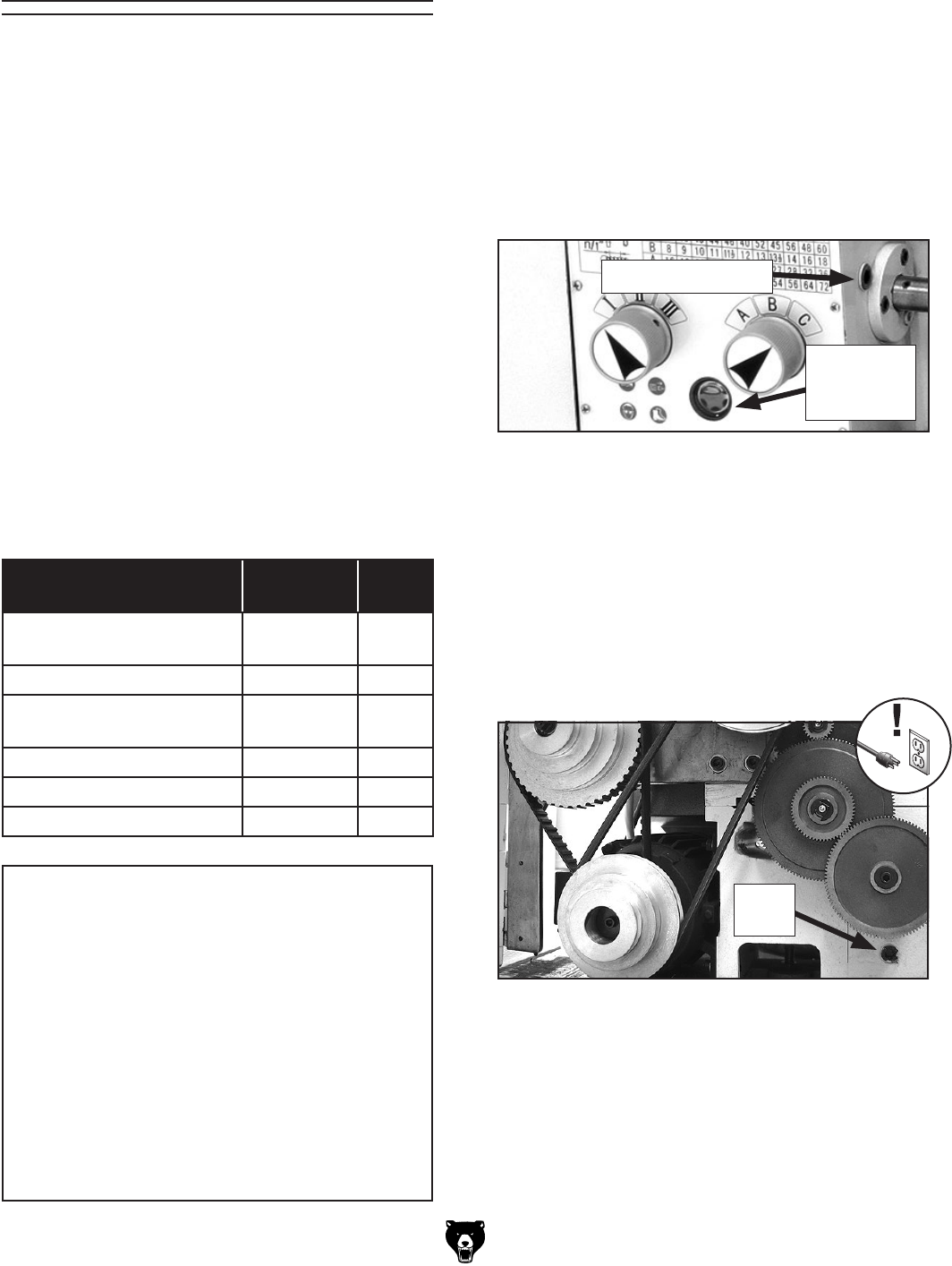
-52- Model G0602/G0752 (Mfg. Since 11/12)
The lathe has numerous metal-to-metal sliding
surfaces that require regular lubrication to main-
tain smooth movement and ensure long-lasting
operation.
Other than the lubrication points covered in this
section, all other bearings are internally lubricated
and sealed at the factory. Simply leave them
alone unless they need to be replaced.
Before performing any lubrication task,
DISCONNECT LATHE FROM POWER!
Important: Before adding lubricant to ball oilers
and grease fittings, clean off entry points to pre-
vent contamination of lubricant.
Use the schedule and information in the chart
below as a daily guide for lubrication tasks.
We recommend using Grizzly Model T23962 or
T23963 lubricants (see Accessories, Page 50) for
most of the lubrication tasks.
Lubrication
Lubrication Task Frequency Page
Ref.
Quick-Change Gearbox Daily This
page
Ball Oilers Daily 53
Leadscrew & Carriage
Rack Daily 54
Bedways Daily 54
Compound Slide Daily 54
Change Gears Annually 55
NOTICE
The recommended lubrication is based on
light-to-medium usage. Keeping in mind
that lubrication helps to protect the value
and operation of the lathe, these lubrication
tasks may need to be performed more fre-
quently than recommended here, depend-
ing on usage.
Failure to follow reasonable lubrication
practices as instructed in this manual could
lead to premature failure of lathe compo-
nents and will void the warranty.
Checking Oil Level
The gearbox reservoir has the proper amount of
oil when the oil level in the sight glass is approxi-
mately 3⁄4 full. The oil sight glass is located below
the gearbox control dials, as shown in Figure 77.
Quick-Change Gearbox
Oil Type .... Grizzly T23962 or ISO 68 Equivalent
Reservoir Capacity ..................................... 1 Pint
Check/Add Frequency ................................. Daily
Change Frequency ................................ Annually
Figure 77. Headstock oil level sight glass.
Gearbox
Oil Level
Sight Glass
Gearbox Fill Plug
After break-in, change the oil in the gearbox, then
again after three months. Afterwards, change
the oil on an annual basis or more frequently if
extreme machine use requires it.
Adding Oil
Use an 8mm hex wrench to remove the gearbox
fill plug (see Figure 77), then add the oil until the
level is approximately 3⁄4 full in the oil sight glass.
Draining Oil
Remove the fill plug (Figure 77), place a catch
pan under the quick-change gearbox drain plug
(see Figure 78). Use an 8mm hex wrench to
loosen the drain plug, remove it, then allow the
reservoir to empty. Re-install the drain plug.
Figure 78. Location of the quick-change gearbox
drain plug.
Drain
Plug
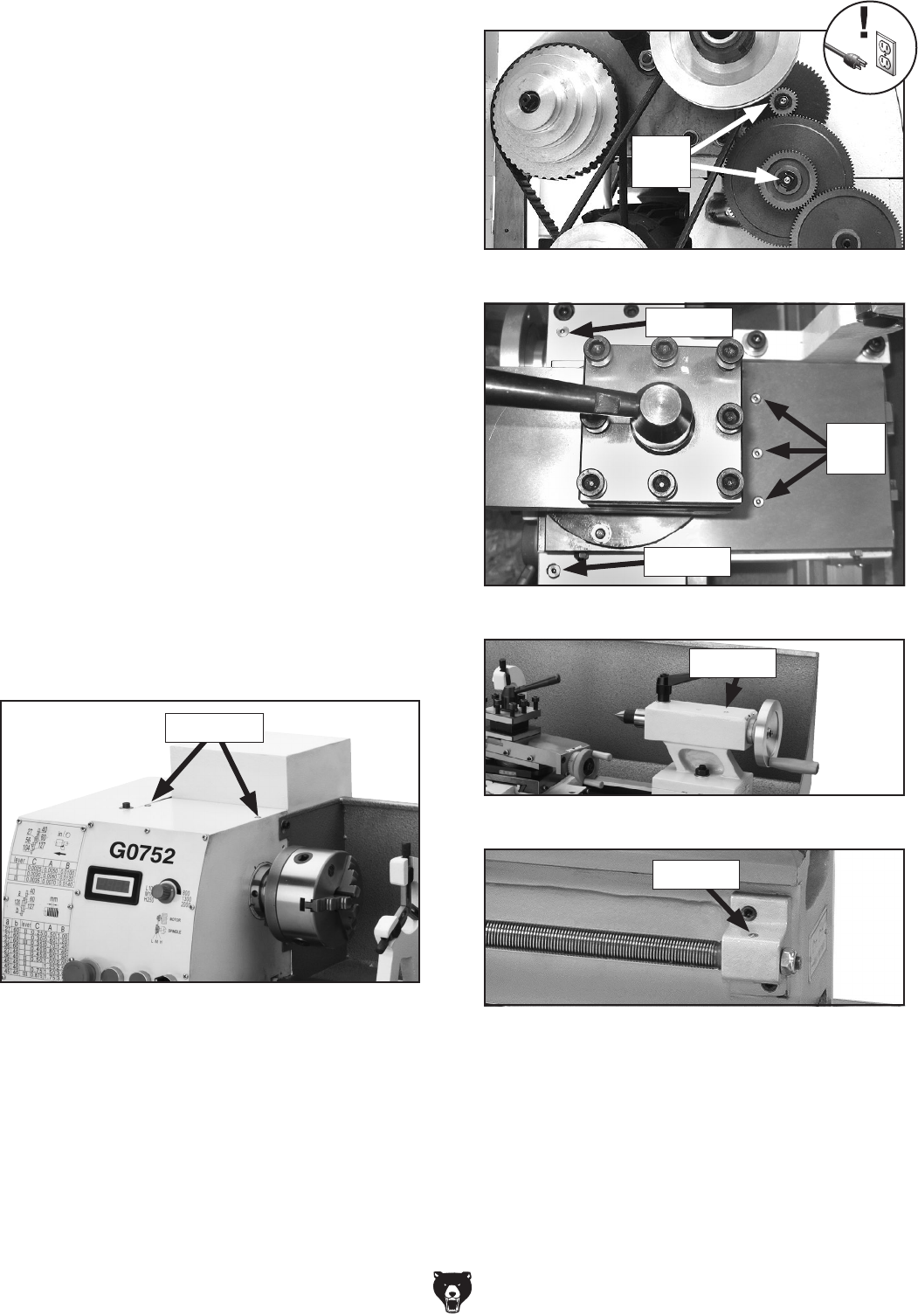
Model G0602/G0752 (Mfg. Since 11/12) -53-
Figure 80. Change gear ball oilers.
Ball Oilers
Oil Type .... Grizzly T23963 or ISO 32 Equivalent
Oil Amount ................................ 1 or 2 Squirts/Fill
Lubrication Frequency ................................. Daily
This lathe has 10 ball oilers that should be oiled
on a daily basis before beginning operation.
Proper lubrication of ball oilers is done with a
pump-type oil can that has a plastic or rubber-
ized cone tip. We do not recommend using metal
needle or lance tips, as they can push the ball too
far into the oiler, break the spring seat, and lodge
the ball in the oil galley.
Lubricate the ball oilers before and after machine
use, and more frequently under heavy use. When
lubricating ball oilers, first clean the outside sur-
face to remove any dust or grime. Push the tip of
the oil can nozzle against the ball oiler to create
a hydraulic seal, then pump the oil can once or
twice. If you see sludge and contaminants coming
out of the lubrication area, keep pumping the oil
can until the oil runs clear. When finished, wipe
away any excess oil.
Refer to Figures 79–83 to identify the location of
each ball oiler.
Figure 79. Spindle bearing ball oilers.
Ball Oilers
Ball
Oilers
Figure 83. Leadscrew end bearing ball oilers.
Figure 82. Tailstock ball oiler.
Figure 81. Carriage and cross slide ball oilers.
Ball
Oilers
Ball Oiler
Ball Oiler
Ball Oiler
Ball Oiler
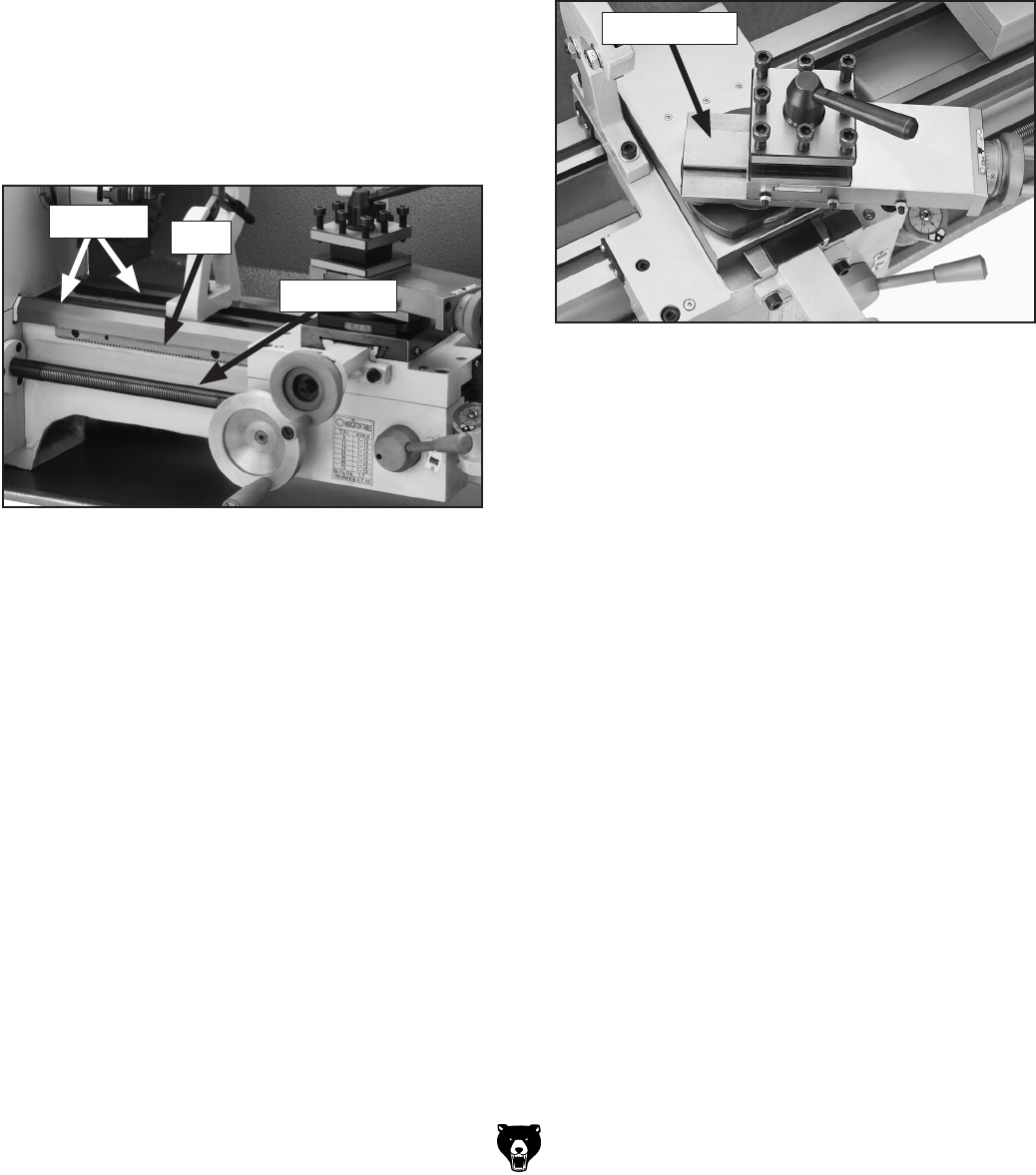
-54- Model G0602/G0752 (Mfg. Since 11/12)
Leadscrew & Carriage Rack
Oil Type .... Grizzly T23962 or ISO 68 Equivalent
Oil Amount ......................................... As Needed
Lubrication Frequency ................................. Daily
Before lubricating the leadscrew and carriage
rack (see Figure 84), clean them first with min-
eral spirits. Use a stiff brush to help remove any
debris or grime. Apply a thin coat of oil along
the length of the carriage rack. Use a stiff brush
to make sure oil is applied into the leadscrew
threads.
Note: In some environments, abrasive material
can become caught in the leadscrew lubricant and
drawn into the half nut. In this case, lubricate the
leadscrew with a quality dry lubricant.
Figure 85. Compound bottom slide.
Compound Slide
Oil Type .... Grizzly T23962 or ISO 68 Equivalent
Oil Amount ............................................Thin Coat
Lubrication Frequency ................................. Daily
Use the handwheel to move the compound slide
all the way toward you (see Figure 85), then wipe
clean the bottom slide with a rag and mild solvent.
Apply the lubricant and move the compound slide
back and forth to distribute the oil.
Figure 84. Leadscrew, rack and bedways.
Rack
Leadscrew
Bedways
Bedways
Oil Type .... Grizzly T23962 or ISO 68 Equivalent
Oil Amount ......................................... As Needed
Lubrication Frequency ................................. Daily
Before lubricating the bedways (see Figure 84),
clean it with mineral spirits. Apply a thin coat
of oil along the length of the bedway. Move the
steady rest, carriage, and tailstock to access the
entire length of the bedways.
Bottom Slide
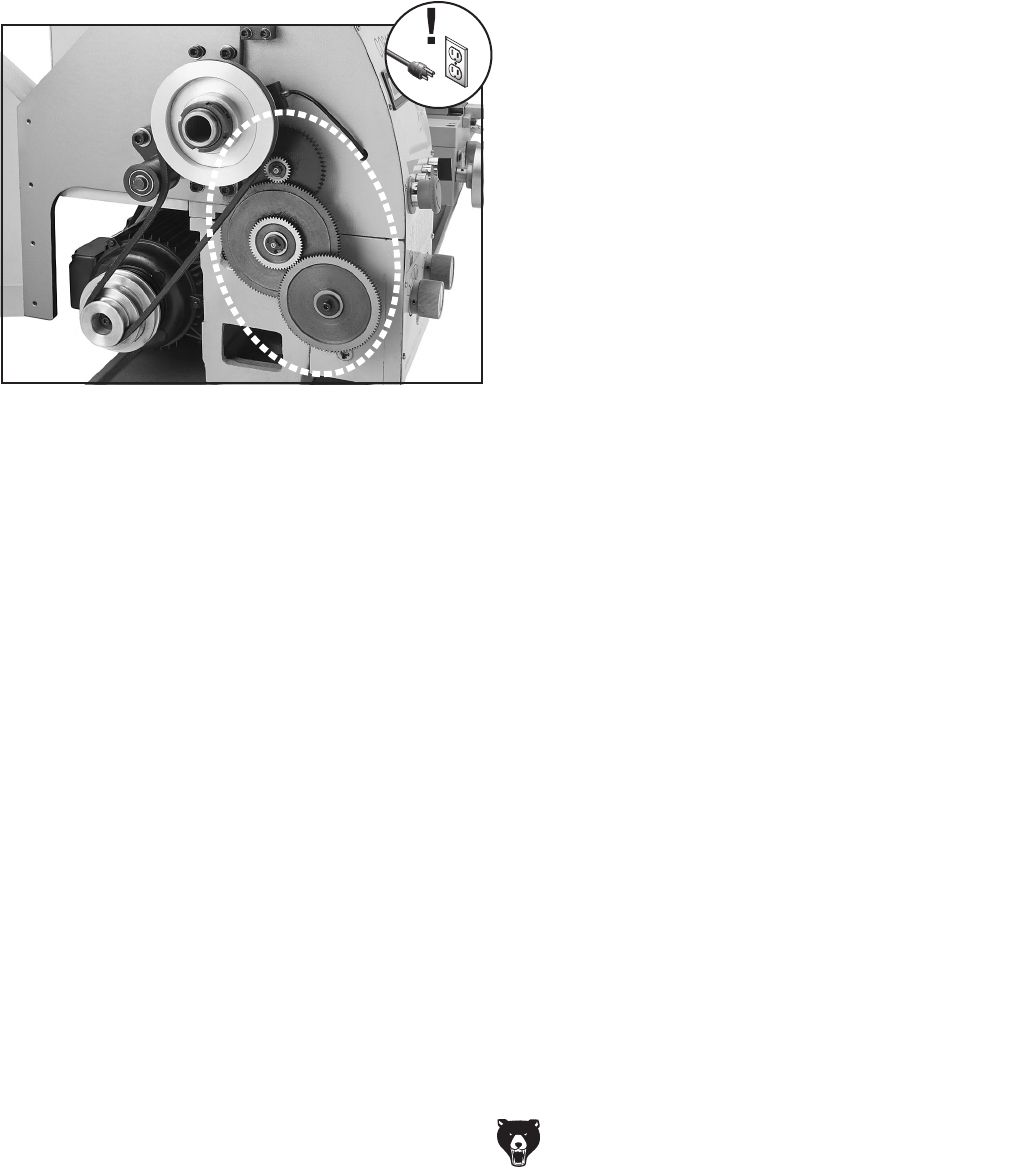
Model G0602/G0752 (Mfg. Since 11/12) -55-
Change Gears
Grease Type ............................................NLGI#2
Oil Amount ............................................Thin Coat
Frequency ............... Annually or When Changing
The change gears, shown in Figure 86, should
always have a thin coat of heavy grease to
minimize corrosion, noise, and wear. Wipe away
excess grease that could be thrown onto the
V-belts and reduce optimal power transmission
from the motor.
Figure 86. Change gears.
To handle and care for the change gears:
Make sure to clean and lubricate any gears you
install or change. Be very careful during handling
and storage—the grease coating on the gears will
easily pickup dirt or debris, which can then spread
to the other gears and increase the rate of wear.
Make sure the change gear cover remains installed
whenever possible to keep the gears free of dust
or debris from the outside environment.
To lubricate the change gears:
1. DISCONNECT LATHE FROM POWER!
2. Open the change gear cover and remove all
the change gears shown in Figure 86.
3. Clean the change gears thoroughly with min-
eral spirits to remove the old grease. Use a
small brush if necessary to clean between the
teeth.
4. Clean the shafts, and wipe away any grease
splatters in the vicinity and on the inside of
the change gear cover.
5. Using a clean brush, apply a thin layer of
grease on the gears. Make sure to get grease
between the gear teeth, but do not fill the
teeth valleys.
6. Install the change gears and mesh them
together with 0.003"–0.008" backlash. Once
the gears are meshed together, apply a small
dab of grease between them where they
mesh together—this grease will be distrib-
uted when the gears rotate and re-coat any
areas scraped off during installation.
7. Close the change gear cover before re-con-
necting the lathe to power.

-56- Model G0602/G0752 (Mfg. Since 11/12)
To prevent the development of rust and corrosion,
the lathe must be properly prepared if it will be
stored for a long period of time. Doing this will
ensure the lathe remains in good condition for
later use.
To prepare the lathe for storage:
1. Run the lathe and bring the gearbox reservoir
to operating temperature, then drain and refill
with clean oil.
2. DISCONNECT LATHE FROM POWER!
3. Thoroughly clean all unpainted, bare metal
surfaces, then apply a liberal coat of way oil,
heavy grease, or rust preventative. Take care
to ensure these surfaces are completely cov-
ered but that the rust preventative or grease
is kept off of painted surfaces.
4. Lubricate the machine as outlined in the
Lubrication section beginning on Page 52.
Be sure to use an oil can to purge all ball oil-
ers and oil passages with fresh oil.
Machine Storage 5. Loosen or remove all belts so they do not
become stretched during the storage period.
(Be sure to place a maintenance note near
the power button as a reminder that the belts
have been loosened or removed.)
6. Cover the lathe and place it in a dry area that
is out of direct sunlight and away from haz-
ardous fumes, paint, solvents, or gas. Fumes
and sunlight can bleach or discolor paint.
7. Every few months do the following:
• Rotate by hand all gear-driven components
a few times in several gear selections. This
will keep the bearings, bushings, gears,
and shafts well lubricated and protected
from corrosion—especially during the win-
ter months.
• Slide the carriage, tailstock, and steady
rest down the lathe bed to make sure that
way spotting is not beginning to occur.

Model G0602/G0752 (Mfg. Since 11/12) -57-
Motor & Electrical
Review the troubleshooting and procedures in this section if a problem develops with your machine. If you
need replacement parts or additional help with a procedure, call our Technical Support at (570) 546-9663.
Note: Please gather the serial number and manufacture date of your machine before calling.
SECTION 7: SERVICE
Troubleshooting
Symptom Possible Cause Possible Solution
Machine does not
start or a circuit
breaker trips.
1. Emergency stop button engaged or at fault.
2. Spindle direction switch turned OFF or at
fault.
3. Start capacitor at fault.
4. Wall fuse/circuit breaker is blown/tripped;
short in electrical system; start-up load too
high for circuit.
5. Wiring is open/has high resistance.
6. Contactor not getting energized/has poor
contacts.
7. Motor connection wired wrong.
8. Motor spindle direction switch at fault.
9. Inverter/control box at fault (G0752 only).
10. Motor at fault.
1. Rotate button clockwise until it pops out to reset it
for operation; replace if not working properly.
2. Turn spindle direciton switch to FWD or REV.
Ensure switch has correct voltage. Replace if faulty.
3. Test/replace if faulty.
4. Verify circuit is rated for machine amp load;
troubleshoot and repair cause of overload; replace
weak breaker; find/repair electrical short.
5. Check for broken wires or disconnected/corroded
connections, and repair/replace as necessary.
6. Test for power on all legs and contactor operation.
Replace unit if faulty.
7. Correct motor wiring connections (Page 67).
8. Replace switch.
9. Inspect inverter/controller box; replace if faulty.
10. Test/repair/replace.
Loud, repetitious
noise coming from
lathe at or near the
motor.
1. Pulley set screws or keys are missing or
loose.
2. Motor fan is hitting the cover.
1. Inspect keys and set screws. Replace or tighten if
necessary.
2. Tighten fan, shim cover, or replace items.
Motor overheats. 1. Motor overloaded. 1. Allow motor to cool; reduce load on motor.
Motor is loud when
cutting, or bogs
down under load.
1. Excessive depth of cut or feed rate.
2. Spindle speed or feed rate wrong for
cutting operation.
3. Cutting tool is dull.
1. Decrease depth of cut or feed rate.
2. Refer to the feeds and speed charts in Machinery's
Handbook or a speeds and feeds calculator on the
internet.
3. Sharpen or replace the cutting tool.

-58- Model G0602/G0752 (Mfg. Since 11/12)
Operation
Symptom Possible Cause Possible Solution
Entire machine
vibrates upon
startup and while
running.
1. Workpiece is unbalanced.
2. Workpiece is hitting stationary object.
3. Loose or damaged V-belt(s).
4. V-belt pulleys are not properly aligned.
5. Chuck or faceplate is unbalanced or not
installed properly.
6. Change gears not aligned or no backlash.
7. Worn or broken gear present.
8. Broken gear or bad bearing.
9. Spindle bearings at fault.
1. Re-install workpiece as centered with the spindle
bore as possible.
2. Stop lathe immediately and correct interference
problem.
3. Re-tension/replace the V-belt(s) as necessary (see
Page 64).
4. Align the V-belt pulleys.
5. Check installation; re-balance chuck or faceplate;
contact a local machine shop for help.
6. Adjust change gears and establish backlash.
7. Inspect gears, and replace if necessary.
8. Replace broken gear or bearing.
9. Reset spindle bearing preload or replace worn
spindle bearings.
Bad surface finish. 1. Wrong spindle speed or feed rate.
2. Dull tooling or poor tool selection.
3. Tool height not at spindle centerline.
4. Too much play in gibs.
1. Adjust for appropriate spindle speed and feed rate.
2. Sharpen tooling or select a better tool for the
intended operation.
3. Adjust tool height to spindle centerline (see Page
40).
4. Tighten gibs (see Page 61).
Tapered tool difficult
to remove from
tailstock quill.
1. Quill is not retracted all the way back into
the tailstock.
2. Contaminants not removed from taper
before inserting into quill.
1. Turn the quill handwheel until it forces the tapered
tool out of quill.
2. Clean the taper and bore, then re-install tool.
Cross slide,
compound rest, or
carriage feed has
sloppy operation.
1. Gibs are out of adjustment.
2. Handwheel is loose or backlash is high.
1. Adjust gibs (see Page 61).
2. Tighten handwheel fasteners, adjust handwheel
backlash to a minimum (see Page 60).
Cross slide,
compound, or
carriage feed
handwheel hard to
move.
1. Dovetail ways loaded with shavings, dust,
or grime.
2. Gib screws are too tight.
3. Backlash setting too tight.
4. Bedways are dry.
1. Clean ways and re-lubricate.
2. Loosen gib screw(s) slightly (see Page 61).
3. Slightly loosen backlash setting (see Page 60).
4. Lubricate bedways/ball oilers.
Cutting tool
or machine
components vibrate
excessively during
cutting.
1. Tool holder not tight enough.
2. Cutting tool sticks too far out of tool holder;
lack of support.
3. Gibs are out of adjustment.
4. Dull cutting tool.
5. Incorrect spindle speed or feed rate.
1. Check for debris, clean, and re-tighten.
2. Re-install cutting tool so no more than 1⁄3 of the total
length is sticking out of tool holder.
3. Adjust gibs at affected component (see Page 61).
4. Replace or resharpen cutting tool.
5. Use the recommended spindle speed and feed rate.

Model G0602/G0752 (Mfg. Since 11/12) -59-
Symptom Possible Cause Possible Solution
Workpiece is
tapered.
1. Headstock and tailstock are not properly
aligned with each other.
1. Re-align the tailstock to the headstock spindle
centerline (see Page 34).
Chuck jaws will
not move or do not
move easily.
1. Chips lodged in the jaws or scroll plate. 1. Remove jaws, clean and lubricate scroll plate and
jaws, then replace jaws.
Carriage will not
feed or is hard to
move.
1. Quick-change gears are not all engaged.
2. Half nut lever engaged.
3. Carriage lock is tightened down.
4. Chips have loaded up on bedways.
5. Bedways are dry and in need of lubrication.
6. Gibs are too tight.
7. Gears or shear pin broken.
1. Adjust gear dials.
2. Disengage half nut lever for manual feeding.
3. Check to make sure the carriage lock bolt is fully
released.
4. Frequently clean away chips that load up during
turning operations and re-lubricate.
5. Lubricate bedways/ball oilers.
6. Loosen gibs screw(s) slightly (see Page 61).
7. Replace gears or shear pin (see Page 62).
Quick-change gear
change dials will not
shift into position.
1. Gears not aligned inside headstock/quick
change gearbox.
1. Rotate spindle by hand with light pressure on the
dial until gear falls into place.
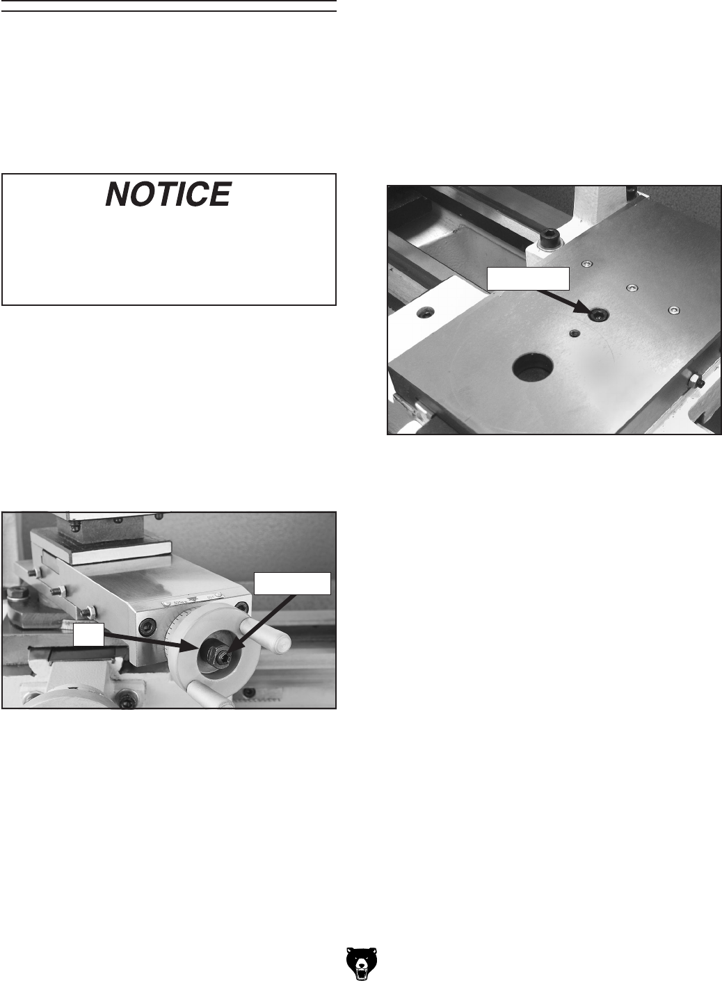
-60- Model G0602/G0752 (Mfg. Since 11/12)
Backlash Adjustment
Backlash is the amount of free play felt while
changing rotation directions with the handwheel.
This can be adjusted on the compound rest and
cross slide leadscrews. Before beginning any
adjustment, make sure all associated compo-
nents are cleaned and lubricated, and the locks
are loose.
Reducing backlash to less than 0.002" is
impractical and can lead to accelerated wear
to the leadscrew and other components.
Avoid the temptation to overtighten the
backlash nut or screw while adjusting.
Compound Rest
Tools Needed: Qty
Hex Wrench 5mm .............................................. 1
Open-End Wrench 10mm .................................. 1
The compound rest backlash is adjusted by loos-
ening or tightening the nut and set screw shown in
Figure 87 to remove play between the handwheel
and the leadscrew collar.
To adjust the backlash, loosen the compound rest
nut and set screw, turn the handwheel counter-
clockwise until the compound rest moves, then
tighten the nut until the backlash is approximately
0.002"–0.003", as indicated on the graduated dial.
Tighten the set screw to secure the setting.
Figure 87. Compound rest backlash adjustment
set screws.
Cross Slide
Tools Needed: Qty
Hex Wrench 4mm .............................................. 1
Hex Wrench 5mm ............................................. 1
Open-End Wrench 14mm .................................. 1
The cross slide backlash is adjusted by loos-
ening the cap screw shown in Figure 88. The
screw pushes down on a wedge and forces the
leadscrew nut apart, taking up lash between the
nut and leadscrew.
To adjust the backlash, remove the compound
rest. Then, rock the cross slide handwheel back
and forth, and tighten the cap screw slowly until
the backlash is approximately 0.002"–0.003" as
indicated on the graduated dial.
If you end up adjusting the nut too tight, loosen
the cap screw, turn the handwheel back and forth
until it turns freely—then try again.
Re-install the compound rest when you are fin-
ished.
Figure 88. Cross slide backlash adjustment cap
screw.
Cap Screw
Nut
Set Screw
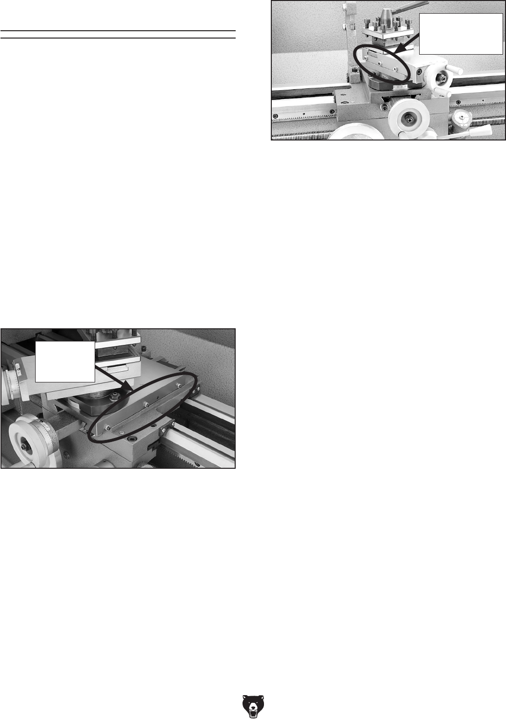
Model G0602/G0752 (Mfg. Since 11/12) -61-
Gib Adjustment
3. Make adjustments in small and equal incre-
ments to the three set screws, then test
the movement of the slide by rotating the
handwheel.
Note: Turning the set screws clockwise will
tighten the gib, and turning them counter-
clockwise will loosen the gib.
4. When you are satisfied with the gib adjust-
ment, keep the set screws from moving and
re-tighten the hex nuts to secure the settings.
5. Re-check the movement of the slide and, if
necessary, repeat Steps 2–4.
Figure 90. Compound slide gib adjustment hex
nuts and set screws.
The goal of adjusting the cross slide and com-
pound slide gibs is to remove sloppiness or "play"
from the ways without making them overly stiff
and difficult to move.
In general, loose gibs cause poor finishes and
tool chatter; however, over-tightened gibs cause
premature wear and make the handwheels dif-
ficult to turn.
Tools Needed Qty
Open-End Wrench 8mm.................................... 1
Hex Wrench 2.5mm ........................................... 1
To adjust the cross slide and compound slide
gibs:
1. DISCONNECT LATHE FROM POWER!
2. Loosen the three hex nuts on the side of the
slide (see Figures 89–90).
Figure 89. Cross slide gib adjustment hex nuts
and set screws.
Cross Slide
Adjustment
Fasteners
Compound Slide
Adjustment
Fasteners
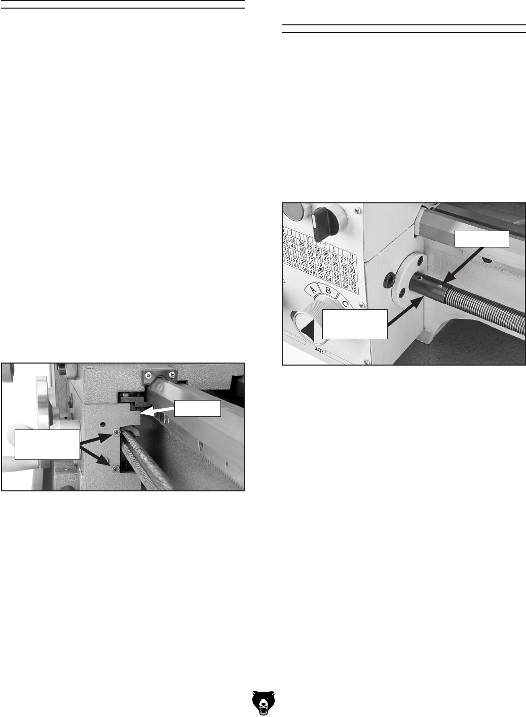
-62- Model G0602/G0752 (Mfg. Since 11/12)
The clamping pressure of the half nut is fully
adjustable with a gib that can be loosened or
tightened by two set screws. Use this procedure
to adjust the half nut if it becomes loose from
wear, or it is too tight for your preferences. A half
nut that is too loose will make it difficult to produce
accurate work; one that is too tight will increase
the rate of wear on itself and the leadscrew.
Tools Needed Qty
Open-End Wrench 8mm.................................... 1
Hex Wrench 5mm .............................................. 1
Hex Wrench 2.5mm ........................................... 1
To adjust the half nut:
1. DISCONNECT LATHE FROM POWER!
2. Disengage the half nut, then remove the
thread dial.
3. Loosen the two adjustment hex nuts shown
in Figure 91, then adjust the set screws in
small, even increments so one end of the gib
does not become tighter than the other.
Half Nut Adjustment
Half-Nut
4. Engage/disengage the half nut several times
and notice how it feels. The adjustment is
correct when the half nut has a slight drag
while opening and closing. The movement
should not be too stiff or too sloppy.
5. Repeat Steps 3–4, if necessary, until you are
satisfied with the half nut pressure.
6. While keeping the set screws from moving,
re-tighten the hex nuts, then re-install the
thread dial.
Figure 91. Typical half nut gib adjustment.
Adjustment
Fasteners
Leadscrew Shear Pin
Replacement
The longitudinal leadscrew is secured to the feed
rate gearing in the headstock with the use of a
soft-metal shear pin (see Figure 92). The shear
pin is designed to break and disengage power
to the leadscrew to help protect more expensive
lathe components if you crash your carriage or
take too large of a cut and overload the lathe.
Contact Grizzly Customer Service at (570) 546-
9663 to order a replacement shear pin (Part #
P0602815).
Tools Needed Qty
Hammer ............................................................. 1
Punch 2.5mm .................................................... 1
To replace the shear pin:
1. DISCONNECT LATHE FROM POWER!
2. Rotate the leadscrew so the shear pin faces
up and down. If the connecting collar rotates
independently from the leadscrew, then
rotate the collar so the shear pin holes align
with those in the leadscrew.
3. Use the punch and hammer to drive out the
pieces of the old shear pin.
4. Make sure the holes in the collar and
leadscrew are aligned, then tap the new
shear pin completely through the holes in the
collar and leadscrew.
Figure 92. Longitudinal leadscrew shear pin.
Shear Pin
Connecting
Collar
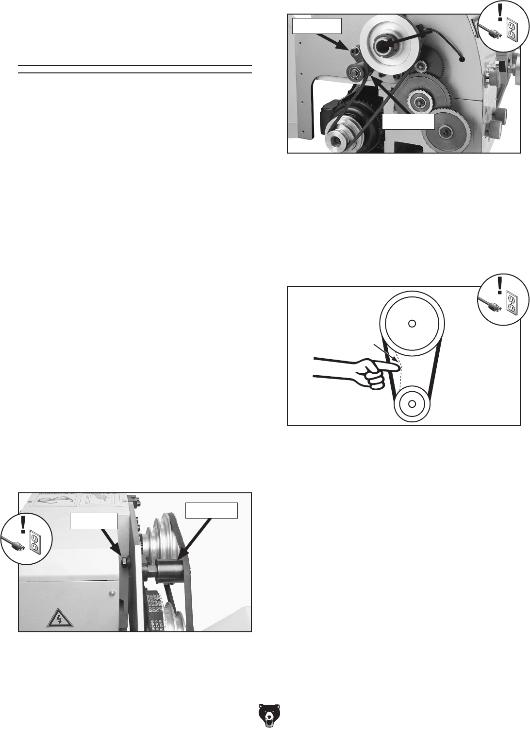
Model G0602/G0752 (Mfg. Since 11/12) -63-
V-Belt Tension &
Replacement
V-Belts stretch and wear with use, so check the
tension on a monthly basis to ensure optimal
power transmission. Replace the V-belts if they
become cracked, frayed, or glazed.
On the Model G0602, the low range V-belt ten-
sion is controlled by a tensioner between the
secondary drive pulley (B) and spindle (C) pulley.
The high range V-belt between the spindle (C)
and motor (A) pulleys is tensioned by the motor.
On the Model G0752, V-belt tension is controlled
by a tensioner between the spindle and motor
pulleys.
Tools Needed Qty
Open-End Wrench 17mm .................................. 1
Hex Wrench 5mm .............................................. 1
Hex Wrench 8mm .............................................. 1
Tensioning V-Belt
To tension the Model G0602 low range V-belt
or Model G0752 V-belt:
1. DISCONNECT LATHE FROM POWER!
2. Open the change gear cover.
3. Loosen the tensioner lock nut (Model G0602)
or tensioner lock bolt (Model G0752) shown
in Figures 93–94.
4. Push the tensioner against the V-belt to ten-
sion it, then secure the tensioner.
The V-belt is correctly tensioned when there
is approximately 1⁄4" deflection when it is
pushed with moderate pressure, as shown in
Figure 95.
Figure 94. Model G0752 tensioner and lock bolt.
—If there is more than 1⁄4" deflection when the
V-belt is pushed with moderate pressure,
loosen the tensioner, adjust it so the ten-
sion is correct, then secure the tensioner.
5. Secure the change gear cover.
Pulley
Deflection
Pulley
Figure 95. Correct V-belt deflection.
1⁄4"
Figure 93. Model G0602 tensioner and lock nut.
Tensioner
Lock Nut
Lock Bolt
Tensioner
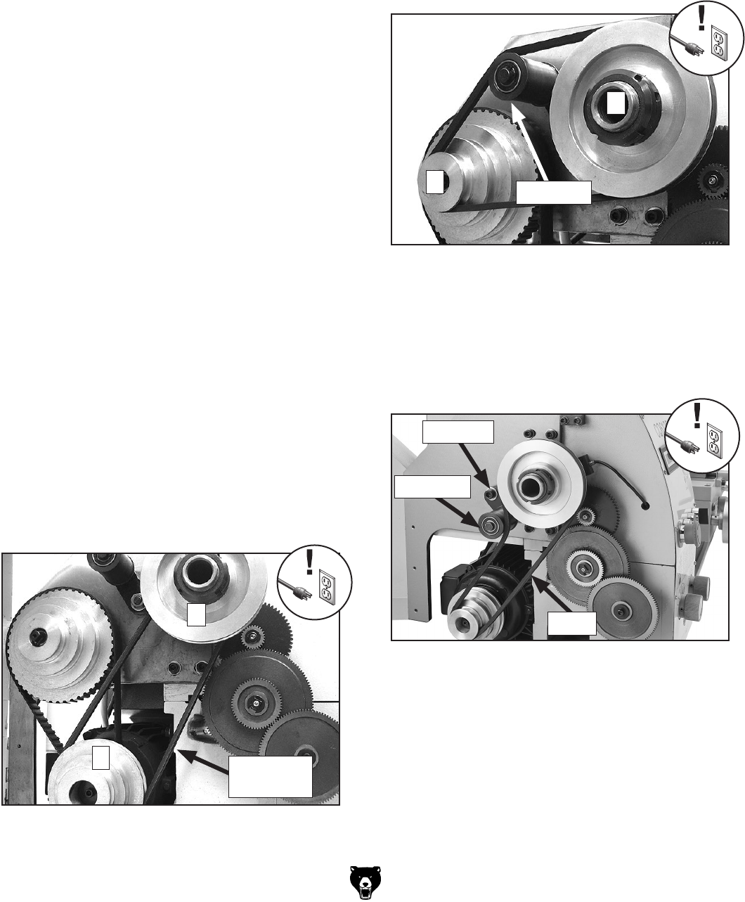
-64- Model G0602/G0752 (Mfg. Since 11/12)
Figure 97. Model G0602 low-range belt.
Model G0752:
Loosen the tensioner lock bolt, then pivot the
tensioner to the left and secure it temporarily.
Remove the V-belt (see Figure 98) and re-install
the new one. Follow Steps 4-5 on Page 63 to ten-
sion the belt.
Figure 98. Model G0752 V-Belt.
V-Belt
Tensioner
C
B
To tension the Model G0602 high range
V-belt:
1. Follow Steps 1–3 in "Tensioning Timing Belt"
on Page 65.
2. Lower the motor and re-tighten the mounting
hex nuts. The high range V-belt is correctly
tensioned when there is approximately 1⁄4"
deflection when it is pushed with moderate
pressure, as shown in Figure 95 on Page 63.
—If there is more than 1⁄4" deflection when
the V-belt is pushed with moderate pres-
sure, loosen the motor mount nuts, lower
the motor as needed, then tighten the nuts.
3. Check the timing belt tension (refer to Step 5
of "Tensioning Timing Belt" on Page 65).
4. Secure the change gear cover.
Replacing V-Belt
1. DISCONNECT LATHE FROM POWER!
2. Open the change gear cover.
3. Model G0602:
—If the high range belt (Figure 96) needs to
be replaced, loosen the motor mount hex
nuts, (see Figure 99 on Page 65), raise
the motor, and carefully roll the belt off of
pulleys A and C. Install a new V-belt, then
follow the steps in "To tension the Model
G0602 high range V-belt" above.
Figure 96. Model G0602 high-range belt.
A
C
High
Range Belt
—If the low range belt between pulleys B and
C (see Figure 97) needs to be replaced,
loosen the tensioner lock nut (see Figure
93 on Page 63), move the tensioner down,
roll the belt off the pulleys, then re-install
the new V-belt. Follow Steps 4-5 on Page
63 to tension the belt.
Lock Bolt
Tensioner
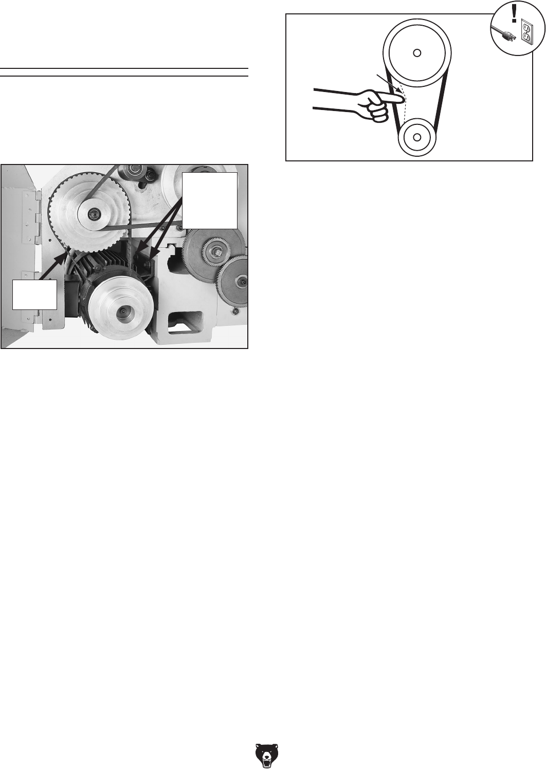
Model G0602/G0752 (Mfg. Since 11/12) -65-
Figure 99. Timing belt and motor mount hex
nuts.
Timing Belt Tension
& Replacement
On the Model G0602 the timing belt transfers
power from the motor to the secondary drive pul-
ley (see Figure 99). If the timing belt becomes
excessively worn or damaged, you will need to
replace it.
Tools Needed Qty
Hex Wrench 5mm .............................................. 1
Open-End Wrench 14mm .................................. 1
Tensioning Timing Belt
1. DISCONNECT LATHE FROM POWER!
2. Open the change gear cover.
3. Loosen the motor mount hex nuts (see
Figure 99).
Note: It may be more convenient to access
the motor mount hex nuts if you first remove
the rear splash guard.
—If there is more than 1⁄4" deflection when
the belt is pushed with moderate pressure,
loosen the motor mount nuts, lower the
motor, adjust belt tension as required, then
tighten the nuts.
—If the high range V-belt is installed, check
the V-belt tension. Refer to "To tension the
Model G0602 high range V-belt" instruc-
tions on Page 64.
6. Secure the change gear cover.
Replacing Timing Belt
1. DISCONNECT LATHE FROM POWER!
2. Open the change gear cover.
3. Loosen the four motor mount hex nuts (see
Figure 99) then remove the low or high range
V-belt (refer to Replacing V-Belt on Page
64).
Note: It may be more convenient to access
the motor mount hex nuts if you first remove
the rear splash guard.
4. Raise the motor up, roll the old timing belt
off the pulleys and replace it with a new one,
making sure that the belt teeth are seated in
the pulley indents.
5. Re-install the high or low range V-Belt—
depending upon your setup (refer to
Replacing V-Belt on Page 64).
6. Tension the timing belt and V-belt. Refer to
Tensioning Timing-Belt on this page, and
the instructions for tensioning the applicable
V-belt on Pages 63– 64.
Pulley
Deflection
Pulley
Figure 100. Correct timing-belt deflection.
1⁄4"
4. Lower the motor and re-tighten the mounting
hex nuts.
Timing
Belt
Motor
Mount
Hex Nuts
(2 of 4)
5. Check the timing belt tension: It is correctly
tensioned when there is approximately 1⁄4"
deflection when it is pushed with moderate
pressure, as shown in Figure 100.

-66- Model G0602/G0752 (Mfg. Since 11/12)
SHOCK HAZARD. Working on wiring that is con-
nected to a power source is extremely dangerous.
Touching electrified parts will result in personal
injury including but not limited to severe burns,
electrocution, or death. Disconnect the power
from the machine before servicing electrical com-
ponents!
MODIFICATIONS. Modifying the wiring beyond
what is shown in the diagram may lead to unpre-
dictable results, including serious injury or fire.
This includes the installation of unapproved after-
market parts.
WIRE CONNECTIONS. All connections must
be tight to prevent wires from loosening during
machine operation. Double-check all wires dis-
connected or connected during any wiring task to
ensure tight connections.
CIRCUIT REQUIREMENTS. You MUST follow
the requirements at the beginning of this man-
ual when connecting your machine to a power
source.
WIRE/COMPONENT DAMAGE. Damaged wires
or components increase the risk of serious per-
sonal injury, fire, or machine damage. If you notice
that any wires or components are damaged while
performing a wiring task, replace those wires or
components.
MOTOR WIRING. The motor wiring shown in
these diagrams is current at the time of printing
but may not match your machine. If you find this
to be the case, use the wiring diagram inside the
motor junction box.
CAPACITORS/INVERTERS. Some capacitors
and power inverters store an electrical charge for
up to 10 minutes after being disconnected from
the power source. To reduce the risk of being
shocked, wait at least this long before working on
capacitors.
EXPERIENCING DIFFICULTIES. If you are expe-
riencing difficulties understanding the information
included in this section, contact our Technical
Support at (570) 546-9663.
Wiring Safety Instructions
The photos and diagrams
included in this section are
best viewed in color. You
can view these pages in
color at www.grizzly.com.
These pages are current at the time of printing. However, in the spirit of improvement, we may make chang-
es to the electrical systems of future machines. Compare the manufacture date of your machine to the one
stated in this manual, and study this section carefully.
If there are differences between your machine and what is shown in this section, call Technical Support at
(570) 546-9663 for assistance BEFORE making any changes to the wiring on your machine. An updated
wiring diagram may be available. Note: Please gather the serial
number and manufacture date of your
machine before calling. This information can be found on the main machine label.
SECTION 8: WIRING
machine
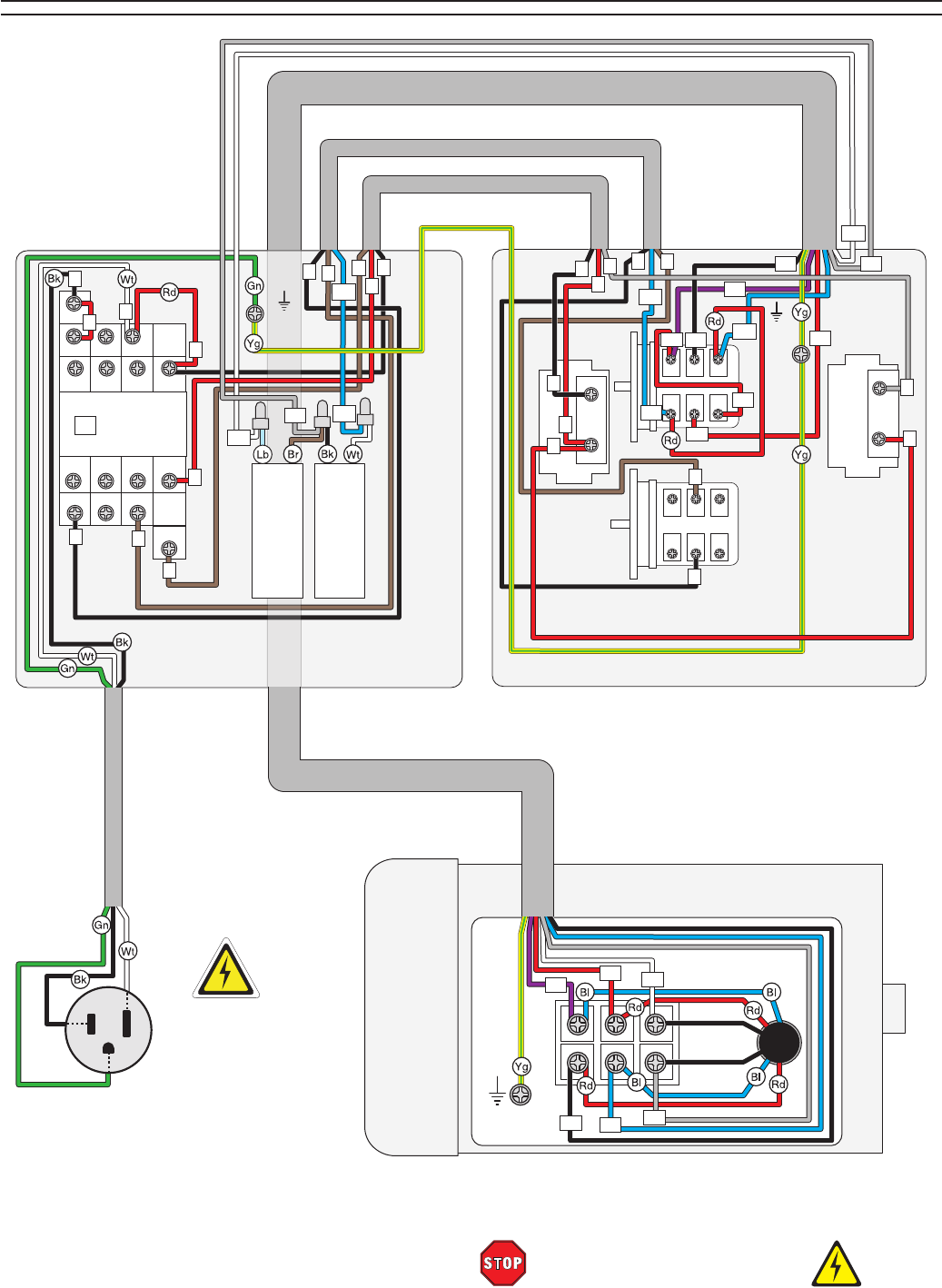
Model G0602/G0752 (Mfg. Since 11/12) -67-
READ ELECTRICAL SAFETY
ON PAGE 66!
G0602 Wiring Diagram
Ground
Motor 1HP 110V
Ground
Front
View
6 102
8 124
Rear
View
7 113
5 91
13NO 21NC 31NC
14NO 22NC 32 NC
4T2
3L2
Siemens
3TB41
22E KM1
CANSEN LW26-20
Start
Button
Switch
E-Stop
Button
Switch
Rotary
Switch
U2 V1 W1
V2
U1
W2
Neutral
Hot
Ground
2
1 NC
MINGER
LA125H-BE101C
3
A2
Gnd
L
N
L
4
4
L
LL
L
N
N
V2
V2
N
V1
V1
3
4
L
V1
Start Capacitor
150 MFD 250VAC
Run Capacitor
20MFD 450VAC
W1
W1
44 NO
6T32T1
43NO
1L1
A1
5L3
N
U1
U1
V1
W2
W2
W2
U2
U2
N
110 VAC
5-15 Plug
(As Recommended)
Control Panel
Wiring Box
V1
(Shown from behind)
2
MINGER
LA125H-BE101C
3
4 NO
4
44
4
L3
3
L
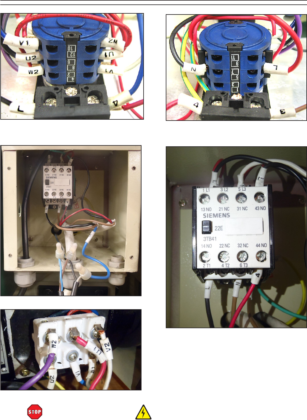
-68- Model G0602/G0752 (Mfg. Since 11/12)
READ ELECTRICAL SAFETY
ON PAGE 66!
Figure 103. Motor connection detail.
G0602 Electrical Components
Figure 101. Spindle direction switch and ON
button.
Figure 102. Electrical box.
Figure 105. Magnetic contactor.
Figure 104. Spindle direction switch and
emergency stop switch.
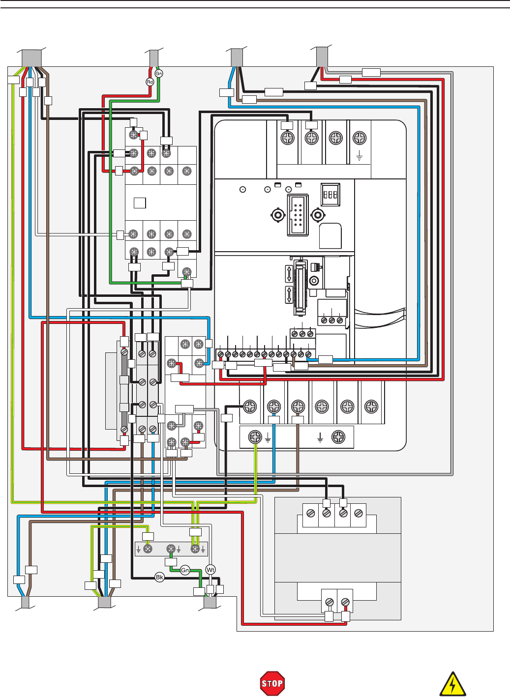
Model G0602/G0752 (Mfg. Since 11/12) -69-
READ ELECTRICAL SAFETY
ON PAGE 66!
G0752 Wiring Box Diagram
21NC 31NC
14NO 22NC 32 NC
4T2
3L2
Siemens
3TB41
22E KM1
A2
44 NO
6T32T1
43NO
5L3
Contactor
1
2A
4
6
OMRON
MY2N-J 220V
5
12
L1 N1
L1 N1
L N
L N
14 13
9
1
Relay
MI1 MI3
MI2 MI4
MI5 DCM 24V AC1
10V RS-485
Port
MI6 DCM ACM
AFM
AVI
M01
MCM
RA RC
RB
AVI
ACI
NPN
PNP
R/L1
READY RUN FAULT ON
1 2 3
U/T1 V/T2 W/T3 +/B1 B2
S/L2 T/L3
Delta
VFD007E11A
VS Drive
1
Transformer
BEIJING AOHENGDA ELECTRICAL
JBK5-40VA
PE 0
110 220
024
V1
W1
N1
N1
L1
L1
DCM
10V
10V
AVI
AVI
ACM
ACM
1L1
A1
3
N1
L1
LN
PE
U1 V1 W1
U1
PE
PE
N1
N1
N1
L1
0
L1
8
8
0
PE
L
N
2
4
3
1
5
50
5
4
Wiring Box
L
N
L
L
N
M1
M1
M2
M2 DCM
PE
PE
13NO
1
DCM
DCM
2
To Left Motor
Junction Box
Page 73
To Circuit Board
Page 71
To Variable Speed
Switch Page 71
To Spindle Direction
Switch Page 71
To Control Panel
Page 71
To Right Motor
Junction Box
Page 73
To Power
Supply
Page 73
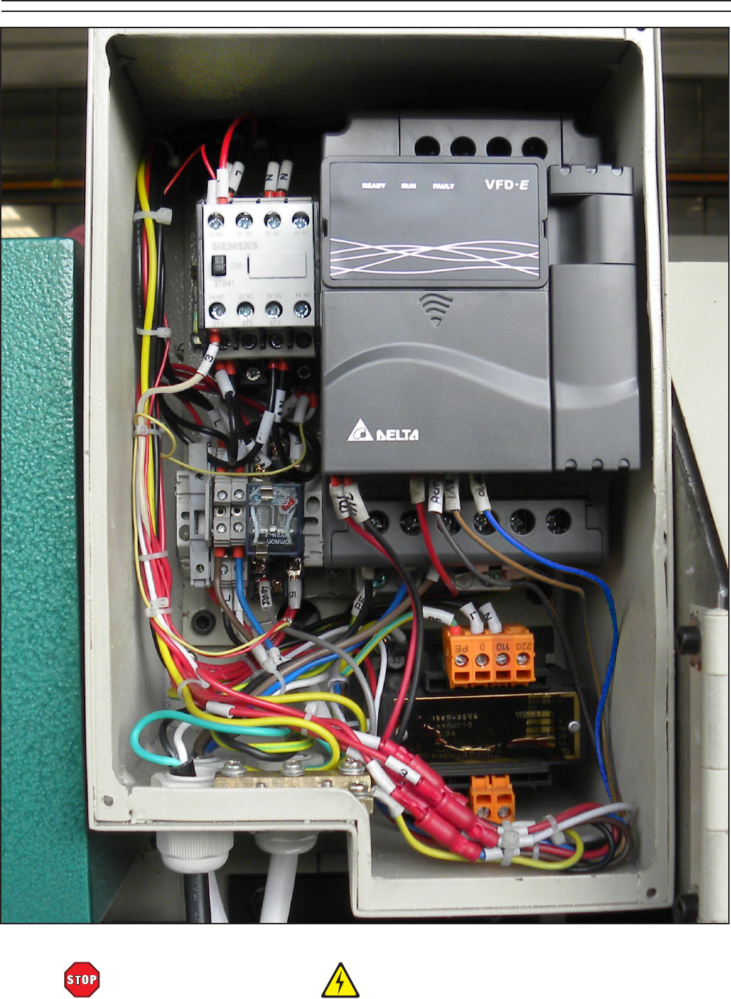
-70- Model G0602/G0752 (Mfg. Since 11/12)
READ ELECTRICAL SAFETY
ON PAGE 66!
Figure 106. G0752 electrical box.
G0752 Wiring Box Components
Model G0602/G0752 (Mfg. Since 11/12) -71-
READ ELECTRICAL SAFETY
ON PAGE 66!
G0752 Control Panel Wiring Diagram
1 NC
LA252HBE102C
23 NO
4
LA252HBE101C
LA252HBE101C
LA252HBE101C
LA252HBE102C
LA252HBE102C
2
2
4
4
VS Switch
RPM Display
Spindle
Speed
Sensor
Spindle Speed
Circuit Board
Spindle
Direction
Switch
OFF Button
Switch
ON Button
Switch
E-Stop
Button Switch
(Viewed from Behind)
Control Panel
WX14-12
4K7
3 NO
3 NO
1 NC
1 NC
(Bottom)(Top)
COM
4
Ground
3
3
3
3
3
3
3
2
2
2
PE
PE
M1
M1
M2
M2
M2
10V
AVI
AVI
ACM
ACM
4
PE
1 NC
LA252HBE102C
2
4
4
5
1
1
1
1
1
1
1
4
DCM
DCM
DCM
5
M1
See Figure 107, on Page 72
See Figure 110,
Page 72
See Figure 108, Page 72
See
Figure 109,
Page 72
To Wiring Box
Page 69
To Wiring Box
Page 69
To Wiring Box
Page 69
See Figure 112,
on Page 72
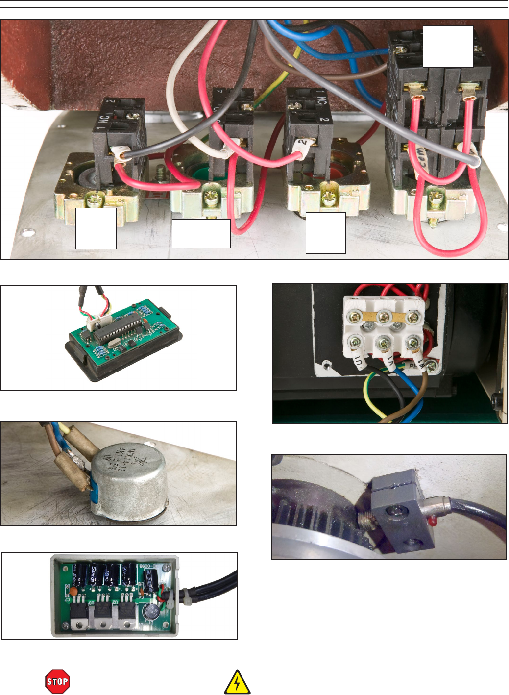
-72- Model G0602/G0752 (Mfg. Since 11/12)
READ ELECTRICAL SAFETY
ON PAGE 66!
G0752 Control Panel Components
Figure 107. Control panel.
Figure 108. RPM display.
Figure 111. Right junction box.
Figure 109. Variable speed potentiometer.
Figure 110. Spindle speed circuit board.
Figure 112. Spindle speed sensor.
E-Stop
Button
Switch
ON Button
Switch
OFF
Button
Switch
Spindle
Direction
Switch
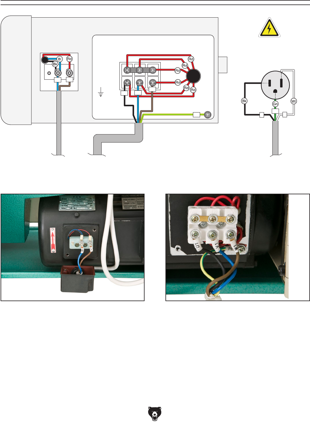
Model G0602/G0752 (Mfg. Since 11/12) -73-
Figure 114. Right motor junction box.Figure 113. Left motor junction box.
G0752 Motor Wiring Diagram
Motor 1HP 220V 3PH
Motor Fan
110V 30W 1PH
Ground
Neutral
Hot
Ground
110 VAC
5-15 Plug
(As Recommended)
U1 W1
N1 L1
PE
LN
V1
PE
To Wiring
Box
Page 69
To Wiring
Box
Page 69
To Wiring
Box
Page 69
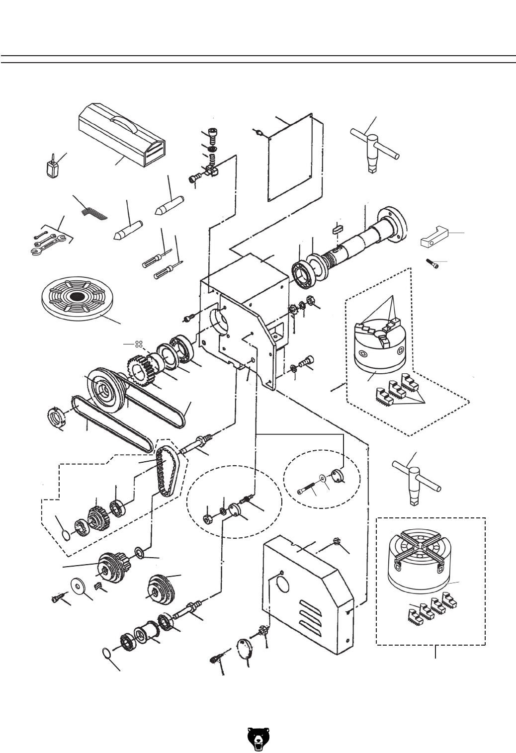
-74- Model G0602/G0752 (Mfg. Since 11/12)
Spindle & Drive Belt
SECTION 9: PARTS
1
2
5
6
7
8
10 11
13
14
15
16
17
18
19
19-1
20 21
22
23
24
25
26
27
54
55
55-1
28
29
30
31
32
33
34
35
36
37 37
37
38
39
40
41
41
42 42
43 40
44
45
46
47
48
49
51
52
53
12
54-4
55-2
54-3
57
3
56
54-2
60
62
64
69 70
63
54-1
LEFT REAR VIEW
(G0602)
(G0752)
(G0602)
(G0602) (G0752)
(G0602)
(G0752)
51
13
55-3
71
72

Model G0602/G0752 (Mfg. Since 11/12) -75-
Spindle & Drive Belt Parts
REF PART # DESCRIPTION REF PART # DESCRIPTION
1 P0602001 HEADSTOCK REAR COVER 37 P0752037 MOTOR PULLEY (G0752)
2 P0602002 PHLP HD SCR M4-.7 X 6 38 P0602038 KEY 6 X 6 X 40
3 P0602003 DEAD CENTER MT#4 39 P0602039 SPACER
5 P0602005 CAP SCREW M6-1 X 25 40 P0602040 STANDOFF STUD M10-1.5 X 50, 15, 25 (G0602)
6 P0602006 FLAT WASHER 6MM 40 P0752040 CAP SCREW M10-1.5 X 20 (G0752)
7 P0602007 COMPRESSION SPRING 41 P0602041 MOUNTING PLATE
8 P0602008 CLAMP 42 P0602042 FLAT WASHER 10MM
10 P0602010 CAP SCREW M6-1 X 25 43 P0602043 HEX NUT M10-1.5 (G0602)
11 P0602011 SPINDLE 44 P0602044 TENSIONER ROLLER SHAFT
12 P0602012 KEY 10 X 10 X 55 45 P0602045 BALL BEARING 6001-2RS
13 P0602013 SPACER 46 P0602046 TENSIONER ROLLER
14 P0602014 TAPERED ROLLER BEARING 32009 48 P0602048 EXT RETAINING RING 12MM
15 P0602015 HEADSTOCK 49 P0602049 CHANGE GEAR COVER
16 P0602016 CAP SCREW M8-1.25 X 20 51 P0602051 HEX NUT M5-.8
17 P0602017 TAPERED ROLLER BEARING 32009 52 P0602052 SPINDLE COVER
18 P0602018 CAP SCREW M6-1 X 20 53 P0602053 PHLP HD SCR M5-.8 X 12
19 P0602019 SPACER 54 P0602054 3-JAW CHUCK 5"
19 P0752019 SPEED SENSOR RING W/MAGNETS 54-1 P0602054-1 3-JAW CHUCK JAW INT 3-PC SET
20 P0602020 GEAR 40T PLASTIC 54-2 P0602054-2 CHUCK BACKPLATE
21 P0602021 V-BELT M-27.5 3L275 (G0602) 54-3 P0602054-3 3-JAW CHUCK KEY
22 P0602022 PULLEY C 54-4 P0602054-4 3-JAW CHUCK JAW EXT 3-PC SET
23 P0602023 V-BELT M-33 3L330 55 P0602055 4-JAW CHUCK 6.5"
24 P0602024 SPANNER NUT 37MM 55-1 P0602055-1 4-JAW CHUCK JAWS 4-PC SET
25 P0602025 BRACKET PLATE 55-2 P0602055-2 4-JAW CHUCK KEY
26 P0602026 LOCK WASHER 10MM 55-3 P0602055-3 4-JAW CHUCK BACKPLATE
27 P0602027 HEX NUT M10-1.5 56 P0602056 FACEPLATE 8"
28 P0602028 FLAT WASHER 10MM 57 P0602057 DEAD CENTER MT#3
29 P0602029 CAP SCREW M5-.8 X 10 60 P0602060 TOOL BOX, EMPTY
30 P0602030 FLAT WASHER 5MM 62 P0602062 HEX WRENCH SET (2.5,3,4,5,6MM)
31 P0602031 GEAR SHAFT 63 P0602063 WRENCH SET (8-10, 12-14, 17-19MM)
32 P0602032 TIMING BELT 263L (G0602) 64 P0602064 BOTTLE FOR OIL
33 P0602033 BALL BEARING 6001ZZ (G0602) 69 P0602069 STANDARD SCREWDRIVER #1
34 P0602034 TIMING PULLEY (G0602) 70 P0602070 PHILLIPS SCREWDRIVER #1
35 P0602035 INT RETAINING RING 12MM (G0602) 71 P0602071 SPINDLE CLAMP
36 P0602036 SPACER 72 P0602072 CAP SCREW M6-1 X 20
37 P0602037 PULLEY A (G0602)
Please Note: We do our best to stock replacement parts whenever possible, but we cannot guarantee that all parts shown here
are available for purchase. Call (800) 523-4777 or visit our online parts store at www.grizzly.com to check for availability.
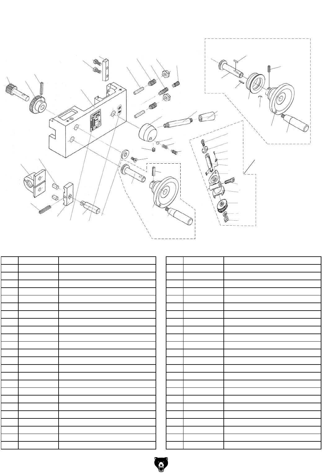
-76- Model G0602/G0752 (Mfg. Since 11/12)
Apron
101
102
103
104
105
106
107
108 109
110
111
112
113
114
115 116 117
118
119
120
121
122
123
124
125
126
127
128
129
130
131
132
133
134
135
136
137
138
139
140
141
142
126-1
G0602 Only
132
133
143
144
145
134
146
136
G0752 Only
REF PART # DESCRIPTION REF PART # DESCRIPTION
101 PRP19M ROLL PIN 4 X 14 126 P0602126 THREAD DIAL BODY
102 P0602102 HALF-NUT 2-PC 126-1 P0602126-1 THREAD DIAL ASSY
103 P0602103 DOWEL PIN 5 X 12 127 P0602127 SIDE GEAR 48T
104 P0602104 GEAR SHAFT 128 PW01M FLAT WASHER 8MM
105 P0602105 GEAR 129 PN03M HEX NUT M8-1.25
106 PRP73M ROLL PIN 4 X 30 130 PSS02M SET SCREW M6-1 X 6
107 P0602107 APRON CASTING 131 P0602131 COMPRESSION SPRING
108 PCAP23M CAP SCREW M4-.7 X 12 132 P0602132 CARRIAGE HANDWHEEL HANDLE
109 P0602109 HALF-NUT GIB 133 P0602133 CARRIAGE HANDWHEEL (G0602)
110 P0602110 DOWEL PIN 4 X 16 133 P0752133 CARRIAGE HANDWHEEL (G0752)
111 PSS34M SET SCREW M5-.8 X 16 134 PRP04M ROLL PIN 4 X 24 (G0602)
112 PSS12M SET SCREW M6-1 X 25 134 PSS04M SET SCREW M6-1 X 12 (G0752)
113 PN06M HEX NUT M5-.8 135 PSS131M SET SCREW M6-1 X 12 CONE-PT
114 PSS04M SET SCREW M6-1 X 12 136 P0602136 GEAR SHAFT (G0602)
115 P0602115 HALF-NUT LEVER HUB 136 P0752136 GEAR SHAFT (G0752)
116 P0602116 HALF-NUT LEVER STUD 137 PFH29M FLAT HD SCR M6-1 X 10
117 P0602117 HALF-NUT LEVER HANDLE 138 PW03M FLAT WASHER 6MM
118 PSTB004M STEEL BALL 5MM 139 P0602139 HALF-NUT INDICATOR PLATE
119 PCAP85M CAP SCREW M6-1 X 6 140 P0602140 LOCK CAM SHAFT
120 P0602120 THREAD DIAL 141 P0602141 THREADED DIAL PLATE
121 PRIV001M RIVET 2 X 5MM STEEL FLUTED 142 P0602142 HALF-NUT BRACKET
122 P0602122 POINTER 143 P0752143 PLATE SPRING (G0752)
123 P0602123 SHAFT 144 P0752144 GRADUATED DIAL (G0752)
124 PK39M KEY 3 X 3 X 10 145 PRP59M ROLL PIN (G0752)
125 PCAP83M CAP SCREW M6-1 X 55 146 PK103M KEY 3 X 3 X 12 (G0752)
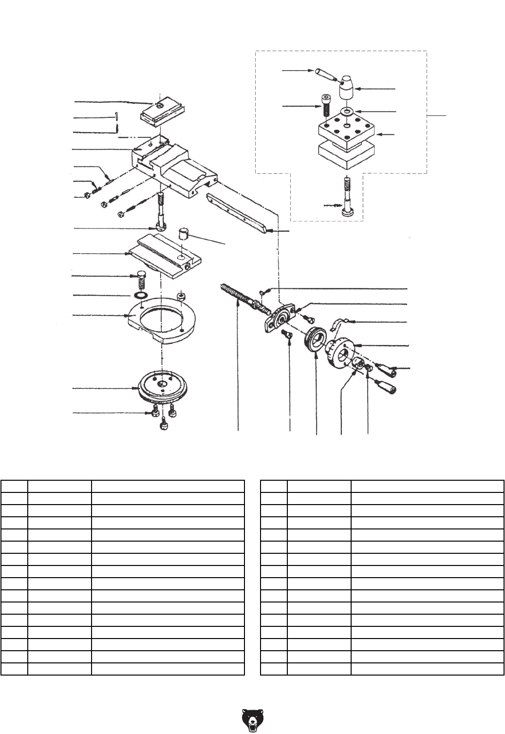
Model G0602/G0752 (Mfg. Since 11/12) -77-
201
202
203
204
205
206
207
208
209
210
211
212
213
214
215
216
217
218
219
220
221
222
223
224
225
226
227
228
229
230 231
208
220A
Tool Post & Compound Rest
REF PART # DESCRIPTION REF PART # DESCRIPTION
201 P0602201 COMPOUND REST 217 PB26M HEX BOLT M8-1.25 X 30
202 P0602202 SWIVEL BASE 218 P0602218 TOOL POST HANDLE
203 P0602203 COMPOUND REST GIB 219 P0602219 TOOL POST HANDLE HUB
204 P0602204 CLAMPING RING 220A P0602220A 4-WAY TOOL POST ASSEMBLY
205 P0602205 GRADUATED DIAL 220 P0602220 TOOL REST
206 P0602206 BARREL NUT 221 P0602221 HUB SPACER
207 P0602207 DOWEL PIN 222 P0602222 TOOL REST SLIDE PLATE
208 P0602208 TOOL POST BOLT 223 P0602223 COMPOUND REST LEADSCREW
209 PW01M FLAT WASHER 8MM 224 P0602224 LEADSCREW MOUNT
210 P0602210 DOWEL PIN 225 P0602225 GRADUATED DIAL
211 P0602211 COMPRESSION SPRING 226 P0602226 COMPOUND REST HANDWHEEL
212 PCAP13M CAP SCREW M8-1.25 X 30 227 P0602227 COMPOUND HANDWHEEL HANDLE
213 PCAP31M CAP SCREW M8-1.25 X 25 228 PK03M KEY 3 X 3 X 8
214 PCAP26M CAP SCREW M6-1 X 12 229 P0602229 POINTER
215 PSS34M SET SCREW M5-.8 X 16 230 P0602230 THREADED COLLAR
216 PN06M HEX NUT M5-.8 231 PSS17M SET SCREW M8-1.25 X 6
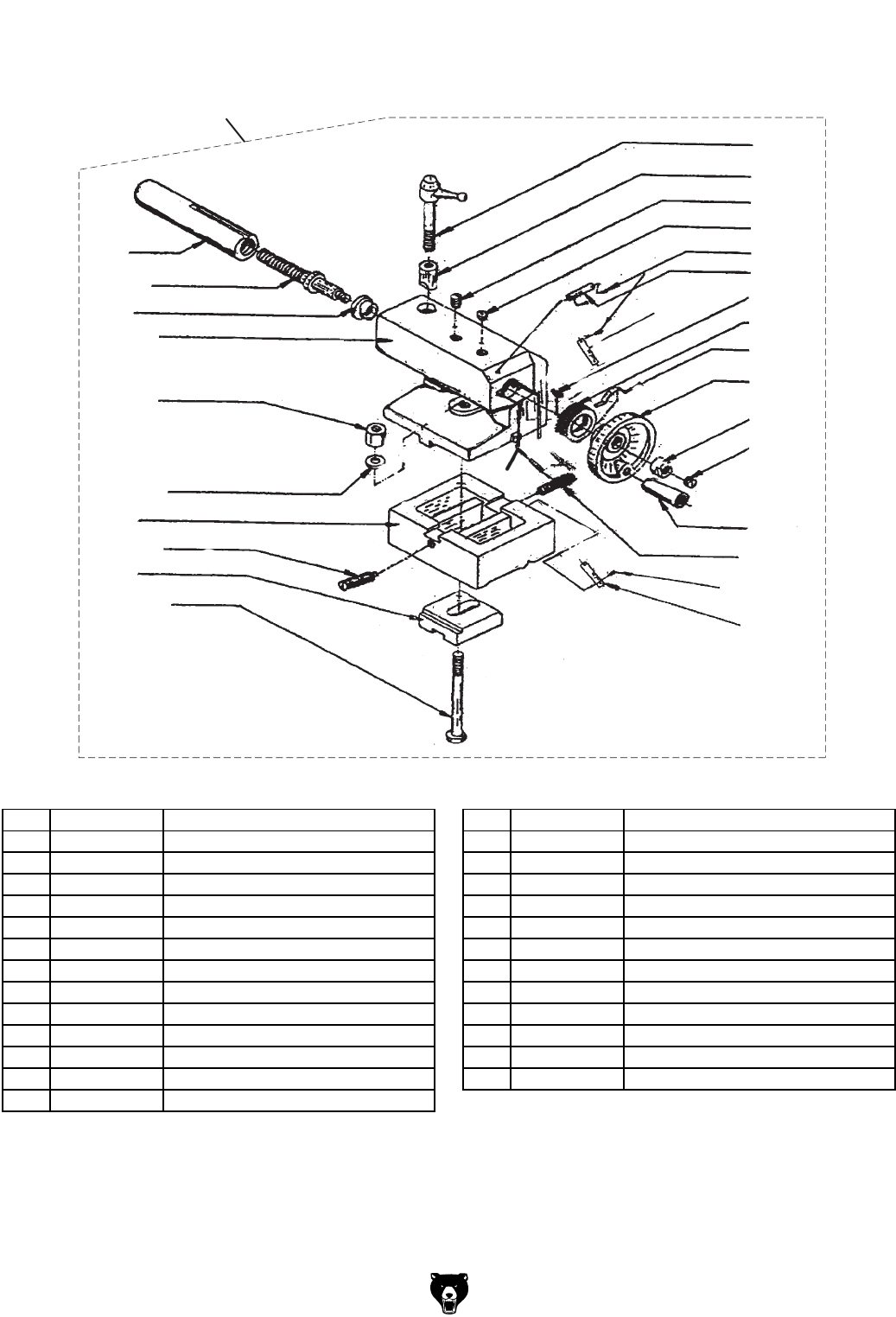
-78- Model G0602/G0752 (Mfg. Since 11/12)
Tailstock
301
302
303
304
305
306
307
308
309
310
311
312
314
315
316 317
318
319
320
321
322
323
324 325
326
313
314
319
300
REF PART # DESCRIPTION REF PART # DESCRIPTION
300 P0602300 COMPLETE TAILSTOCK ASSY 314 PSS21M SET SCREW M8-1.25 X 25
301 P0602301 TAILSTOCK QUILL 315 P0602315 TAILSTOCK HANDWHEEL HANDLE
302 P0602302 TAILSTOCK LEADSCREW 316 P0602316 UPPER OFFSET PLATE
303 P0602303 BUSHING 317 PK39M KEY 3 X 3 X 10
304 P0602304 HANDWHEEL SCALE PLATE 318 PLN05M LOCK NUT M10-1.5
305 P0602305 TAILSTOCK HANDWHEEL 319 PRIV001M RIVET 2 X 5MM STEEL FLUTED
306 P0602306 LEVER BOLT M12-1.75 X 50 320 P0602320 BALL OILER 10MM
307 P0602307 BARREL NUT M12-1.75 321 P0602321 CLAMPING PLATE
308 PSS04M SET SCREW M6-1 X 12 322 PN09M HEX NUT M12-1.75
309 P0602309 GRADUATED DIAL 323 PB158M HEX BOLT M12-1.75 X 90
310 P0602310 TAILSTOCK HANDWHEEL POINTER 324 PW06M FLAT WASHER 12MM
311 P0602311 HANDWHEEL BUSHING 325 PSS26M SET SCREW M5-.8 X 6
312 P0602312 TAILSTOCK BODY 326 P0602326 LOWER OFFSET PLATE
313 P0602313 TAILSTOCK BASE
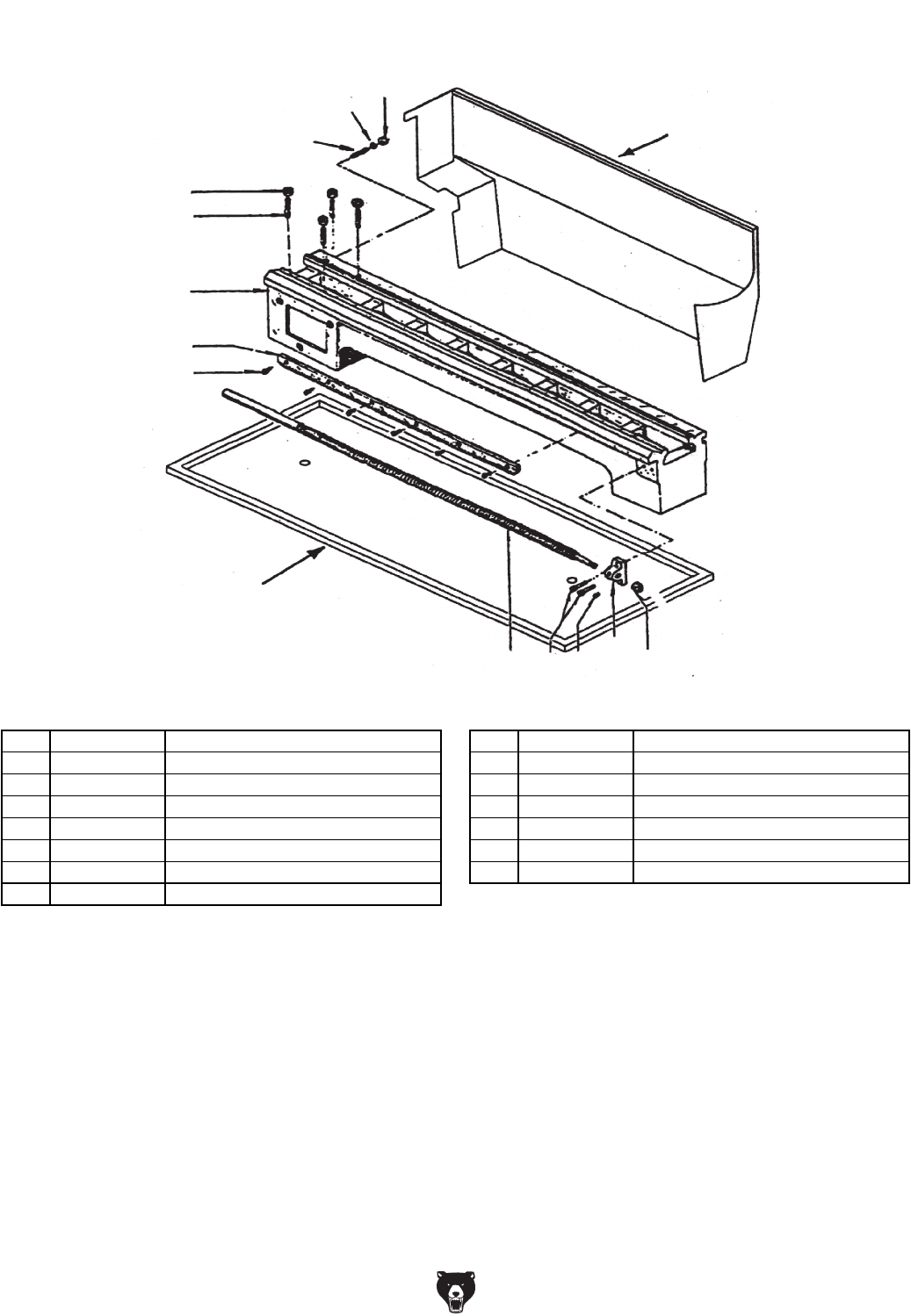
Model G0602/G0752 (Mfg. Since 11/12) -79-
Bed & Leadscrew
401
402
403
404 405
406
407 408
409
410
411
412
413 414
415
REF PART # DESCRIPTION REF PART # DESCRIPTION
401 P0602401 BED 409 P0602409 BACK SPLASH
402 P0602402 RACK 410 P0602410 STUD-SE M10-1.5 X 45, 35
403 PCAP33M CAP SCREW M5-.8 X 12 411 PN02M HEX NUT M10-1.5
404 P0602404 LONGITUDINAL LEADSCREW 412 PSS44M SET SCREW M8-1.25 X 40
405 P0602405 LEADSCREW END BRACKET 413 PW01M FLAT WASHER 8MM
406 P0602406 BALL OILER 6MM 414 PN03M HEX NUT M8-1.25
407 PCAP02M CAP SCREW M6-1 X 20 415 P0602415 CHIP PAN
408 PLN05M LOCK NUT M10-1.5
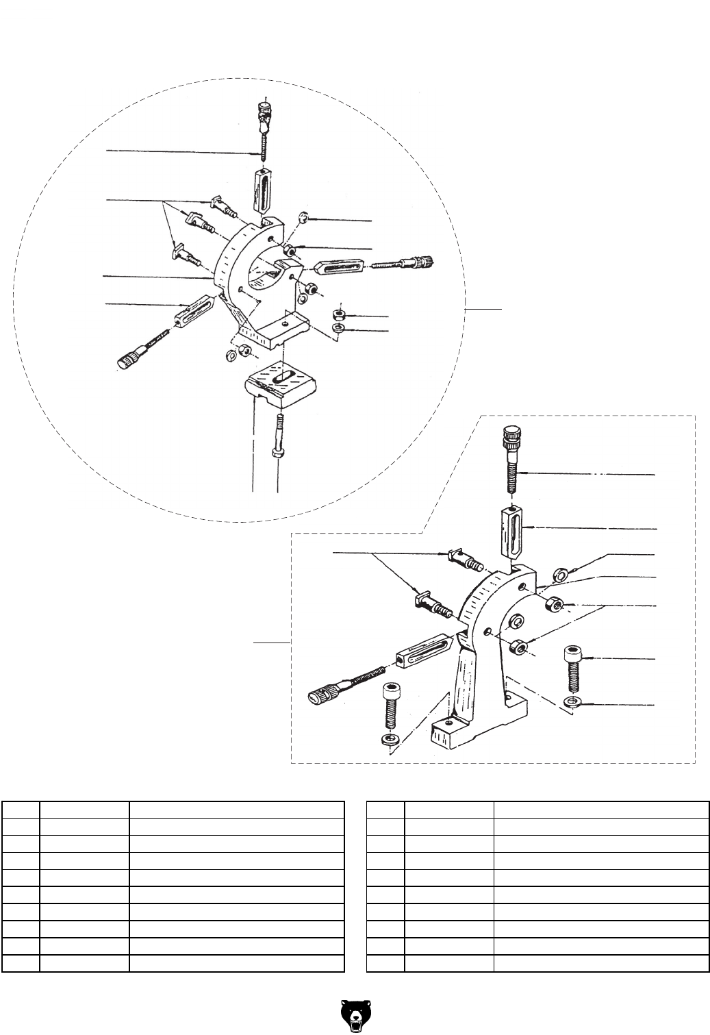
-80- Model G0602/G0752 (Mfg. Since 11/12)
Steady Rest & Follow Rest
501
502
503
504
505
506
507 508
509
511
512
513
514
511A
515
516
517
518
510 501A
REF PART # DESCRIPTION REF PART # DESCRIPTION
501A P0602501A STEADY REST ASSEMBLY 510 PN09M HEX NUT M12-1.75
501 P0602501 STEADY REST CASTING 511A P0602511A FOLLOW REST ASSEMBLY
502 P0602502 FINGER 511 P0602511 FOLLOW REST CASTING
503 P0602503 SHOULDER T-BOLT 512 P0602502 FINGER
504 PLW03M LOCK WASHER 6MM 513 P0602503 SHOULDER T-BOLT
505 PN01M HEX NUT M6-1 514 P0602506 ADJUSTING SCREW
506 P0602506 ADJUSTING SCREW 515 PN01M HEX NUT M6-1
507 P0602507 CLAMPING PLATE 516 PLW03M LOCK WASHER 6MM
508 PB125M HEX BOLT M12-1.75 X 65 517 PCAP40M CAP SCREW M8-1.25 X 35
509 PW06M FLAT WASHER 12MM 518 PW01M FLAT WASHER 8MM
Model G0602/G0752 (Mfg. Since 11/12) -81-
G0602 Motor & Electrical
601
602
603
604
607
608
610
611V2
611V2-2
611V2-3
611V2-4
611V2-6
612
615
617
616
611V2-5
611V2-7
611V2-1
618
620
619
621
REF PART # DESCRIPTION REF PART # DESCRIPTION
601 P0602601 ELECTRICAL CABINET 611V2-5 P0602611V2-5 CAPACITOR COVER
602 PCAP06M CAP SCREW M6-1 X 25 611V2-6 P0602611V2-6 POWER CORD 14G 3W 60" 5-15P
603 PLW03M LOCK WASHER 6MM 611V2-7 P0602611V2-7 MOTOR JUNCTION BOX
604 P0602604 ELECTRICAL CABINET COVER 612 PW05M FLAT WASHER 4MM
607 P0602607 STRAIN RELIEF NUT 615 P0602615 STRAIN RELIEF M20-1.5
608 P0602608 STRAIN RELIEF M25-1.5 616 P0602616 STRAIN RELIEF NUT
610 PS17M PHLP HD SCR M4-.7 X 6 617 P0602617 CONTACTOR SIEMENS 3TB41 22E 110V
611V2 P0602611V2 MOTOR 1HP 110V 1-PH ALUM BDY V2.09.08 618 P0602618 E-STOP BUTTON MINGER LA125H-BE102C
611V2-1 P0602611V2-1 MOTOR FAN 619 P0602619 ON PUSH BUTTON MINGER LA125H-BE101C
611V2-2 P0602611V2-2 MOTOR FAN COVER 620 P0602620 ROTARY SWITCH CANSEN LW26-20 M09T/3
611V2-3 PC150 S CAPACITOR 150M 125V 621 P0602621 G0602 CONTROL PANEL
611V2-4 P0602611V2-4 R CAPACITOR 20M 400V

-82- Model G0602/G0752 (Mfg. Since 11/12)
G0752 Motor & Electrical
611
611-1
611-2
611-3 611-4
611-6
602
601
604
603
607
617
618
619
630
631
632
633
620
634
621 608
610
612
622
623
624
627
628
629
626
625
4
6
KAI
DYF08A
5
1
REF PART # DESCRIPTION REF PART # DESCRIPTION
601 P0752601 ELECTRICAL CABINET 619 P0752619 TERMINAL POST
602 PCAP06M CAP SCREW M6-1 X 25 620 P0752620 VS DRIVE DELTA VFD007E11A
603 PLW03M LOCK WASHER 6MM 621 P0752621 VFD-E USER MANUAL
604 P0752604 ELECTRICAL CABINET COVER 622 P0752622 E-STOP BUTTON MINGER LA125H-BE101C-102C
607 P0602607 STRAIN RELIEF NUT 623 P0752623 ON PUSH BUTTON MINGER LA125H-BE102C
608 P0602608 STRAIN RELIEF M25-1.5 624 P0752624 SPINDLE DIRECTION SWITCH LA125H-BE102C
610 PS17M PHLP HD SCR M4-.7 X 6 625 P0752625 G0752 CONTROL PANEL
611 P0752611 MOTOR 1HP 220V 3-PH 626 P0752626 OFF PUSH BUTTON MINGER LA125H-BE101C
611-1 P0752611-1 MOTOR FAN 627 P0752627 RPM DISPLAY UNIT
611-2 P0752611-2 MOTOR FAN COVER 628 P0752628 POTENTIOMETER WX14-12 4K7
611-3 P0752611-3 RIGHT MOTOR JUNCTION BOX COVER 629 P0752629 SPINDLE SPEED SENSOR
611-4 P0752611-4 LEFT MOTOR JUNCTION BOX COVER 630 P0752630 RELAY OMRON MY2N-J 220V
611-6 P0602611-6 POWER CORD 16G 3W 60" 5-15P 631 P0752631 FUSE 2A 250V
612 PW05M FLAT WASHER 4MM 632 P0752632 FUSE HOLDER
617 P0602617 CONTACTOR SIEMENS 3TB41 22E 110V 633 P0752633 TERMINAL POST MOUNTING BRACKET
618 P0752618 TRANSFORMER BAEEC JBK5-40VA 634 P0752634 GROUNDING BAR

Model G0602/G0752 (Mfg. Since 11/12) -83-
701
702
703
704
706
707
708
711
712
713
714 715
716
717
718
719
720
723
724
725
726
727
729
728
730
731
732
733
734
735
736
737
739
740
741
721
722
REF PART # DESCRIPTION REF PART # DESCRIPTION
701 PSS01M SET SCREW M6-1 X 10 723 P0602723 GEAR 104T
702 P0602715 KEYED BUSHING 724 PW03M FLAT WASHER 6MM
703 P0602703 GEAR 60T PLASTIC 725 PCAP85M CAP SCREW M6-1 X 6
704 P0602704 GEAR 27T CAST-IRON 726 PLW04M LOCK WASHER 8MM
706 P0602706 GEAR SHAFT 727 PCAP12M CAP SCREW M8-1.25 X 40
707 PEC10M E-CLIP 9MM 728 P0602728 GEAR 36T
708 P0602708 BALL OILER 6MM 729 P0602729 GEAR 36T
711 P0602711 BRACKET 730 P0602730 GEAR 40T
712 P0602712 T-NUT 731 P0602731 GEAR 44T
713 P0602713 SPACER WASHER 732 P0602732 GEAR 46T
714 P0602714 GEAR SHAFT 733 P0602733 GEAR 48T
715 P0602715 KEYED BUSHING 734 P0602734 GEAR 52T
716 P0602716 GEAR 127T 735 P0602735 GEAR 45T
717 P0602717 GEAR 56T 736 P0602736 GEAR 56T
718 P0602718 GEAR SHAFT CLIP 737 P0602737 GEAR 60T
719 P0602708 BALL OILER 6MM 738 P0602703 GEAR 60T PLASTIC
720 P0602720 BUSHING 739 P0602739 GEAR 104T
721 PK97M KEY 4 X 4 X 14 740 P0602740 GEAR 120T
722 P0602722 SPACER RING 741 P0602741 GEAR 127T
Change Gears
-84- Model G0602/G0752 (Mfg. Since 11/12)
Gearbox
801
802 803
804
806
807
808
809
810
811
812
813
814
815
816
817
818
819
820
821
822
823
824
825
826
828
829
830
831
832
833
834
835
836
837
838
839
840
841 842
843
844 845
846 847 848
849
850
805
805
802
827
822
822
820
822
823

Model G0602/G0752 (Mfg. Since 11/12) -85-
REF PART # DESCRIPTION REF PART # DESCRIPTION
801 P0602801 PLUG 826 P0602826 COLLAR
802 P0602802 O-RING 827 PK132M KEY 4 X 4 X10
803 P0602803 BUSHING 828 P0602828 GEAR SHAFT
804 P0602804 CLUSTER GEAR 30/36/33T 829 P0602829 GEAR 33T
805 PK133M KEY 4 X 4 X 50 830 P0602830 GEAR 30T
806 P0602806 GEAR SHAFT 831 P0602831 GEAR 35T
807 P0602807 BUSHING 832 P0602832 FLANGE
808 P0602808 CLUSTER GEAR 22/44/33T 833 PCAP01M CAP SCREW M6-1 X 16
809 P0602809 CLUSTER GEAR PLUG 834 P0602834 SHIFT FORK
810 PCAP50M CAP SCREW M5-.8 X 10 835 P0602835 FRONT GEARBOX COVER
811 P0602811 REAR GEARBOX COVER 836 PRP05M ROLL PIN 5 X 30
812 P0602812 FILL PLUG 3/8" NPT 837 P0602837 COMPRESSION SPRING
813 P0602813 GEAR BOX CASE 838 P0602838 SIGHT GLASS A16
814 P0602814 DRAIN PLUG 3/8" NPT 839 P0602839 POINTER DISC
815 P0602815 SHEAR PIN 5 X 20 840 PSS01M SET SCREW M6-1 X 10
816 P0602816 LEADSCREW CONNECTING COLLAR 841 PSTB004M STEEL BALL 5MM
817 P0602817 SHEAR PIN 5 X 20 842 P0602842 SHIFT HUB
818 PCAP26M CAP SCREW M6-1 X 12 843 PSS01M SET SCREW M6-1 X 10
819 P0602819 FLANGE 844 PCAP37M CAP SCREW M6-1 X 50
820 P6202-OPEN BALL BEARING 6202-OPEN 845 PCAP02M CAP SCREW M6-1 X 20
821 P0602821 GEAR 33T 846 P0602846 O-RING 1.8 X 6.7
822 PR05M EXT RETAINING RING 15MM 847 P0602847 SHAFT
823 PK65M KEY 4 X 4 X 8 848 PRP03M ROLL PIN 5 X 20
824 P0602824 GEAR SHAFT 22T 849 P0602849 SHIFT LEVER
825 P0602825 GEAR 44T 850 P0602850 SHIFT FORK
Gearbox Parts List
-86- Model G0602/G0752 (Mfg. Since 11/12)
Cross Slide & Carriage
901
902A
903
904
905
906
907
908
909
910
911
912
913
914
915
916 917
918
919
920
921
922
923
924
925
926
927
928
929
930
931
932
933
934
935
936 937
938
939
REF PART # DESCRIPTION REF PART # DESCRIPTION
901 P0602901 SADDLE 921 P0602921 DOWEL PIN
902A P0602902A CROSS SLIDE W/O T-SLOTS V2.08.07 922 PSS34M SET SCREW M5-.8 X 16
903 P0602903 CROSS SLIDE GIB 923 PN06M HEX NUT M5-.8
904 P0602904 CROSS SLIDE LEADSCREW NUT 924 P0602924 SADDLE TENSION BAR
905 P0602905 CROSS SLIDE LEADSCREW 925 PW03M FLAT WASHER 6MM
906 P0602906 LEADSCREW BRACKET 926 PCAP01M CAP SCREW M6-1 X 16
907 PCAP31M CAP SCREW M8-1.25 X 25 927 P0602927 SADDLE CLAMP PLATE
908 P0602908 INDICATOR PLATE 928 PSS25M SET SCREW M6-1 X 20
909 PRIV001M RIVET 2 X 5MM STEEL FLUTED 929 PN01M HEX NUT M6-1
910 P0602910 GRADUATED DIAL 930 PCAP48M CAP SCREW M6-1 X 35
911 PK105M KEY 3 X 3 X 6 931 P0602931 V-WAY WIPER
912 P0602912 SPRING PLATE 932 P0602932 V-WAY WIPER COVER
913 P0602913 CROSS SLIDE HANDWHEEL 933 PS07M PHLP HD SCR M4-.7 X 8
914 P0602914 HANDWHEEL HEX NUT 934 P0602934 STRAIGHT WAY WIPER
915 PSS17M SET SCREW M8-1.25 X 6 935 P0602935 STRAIGHT WAY WIPER COVER
916 P0602916 CROSS SLIDE HANDWHEEL HANDLE 936 P0602936 BALL OILER 6MM
917 P0602917 SLIDE BLOCK 937 PCAP40M CAP SCREW M8-1.25 X 35
918 P0602918 CHIP GUARD 938 PCAP48M CAP SCREW M6-1 X 35
919 PCAP26M CAP SCREW M6-1 X 12 939 P0602939 HANDLE SCREW
920 PSS11M SET SCREW M6-1 X 16
Model G0602/G0752 (Mfg. Since 11/12) -87-
G0602 Labels & Cosmetic
./4)#%
$/./4#(!.'%"%47%%.
()'(,/77(),%25..).'
./4)#%
$!-!'%7),,/##52)&
#!22)!'%&%%$3).4/
(%!$34/#+/24!),34/#+
-/$%,'8 ,!4(%
&!),52% 4/ &/,,/7 4(%3% 7!2.).'3 7),, 2%35,4 ). 3%2)/53
0%23/.!,).*529
2%!$!.$5.$%234!.$-!.5!,"%&/2%34!24).'-!#().%
!,7!937%!2!.3)!002/6%$3!&%49',!33%3
0,5'0/7%2#/2$).4/'2/5.$%$/54,%4/.,9
+%%0'5!2$3!.$%9%3()%,$3).0,!#%$52).'!,,/0%2!4)/.3
$/./47%!2,//3%#,/4().'',/6%3/2*%7%,293%#52%,/.'
(!)2!.$"544/.!,,,/.'3,%%6%3()243
$)3#/..%#40/7%202)/24/3%26)#).'3%44).'50/2!$*534).'
$/./4%80/3%4/2!)./2$!-0.%33
$/./4/0%2!4%5.$%24(%).&,5%.#%/&$25'3/2!,#/(/,/2
7(%.4)2%$
-!+%352%-!#().%)302/0%2,9!$*534%$!.$3%450#/22%#4,9
"%&/2%34!24).'-/4/2
"%&/2%34!24).'-!#().%-!+%#%24!).-!#().%2%3433%#52%,9
/.&,!4,%6%,'2/5.$
$/./4,%!6%!#(5#++%9).$2),,#(5#+/2,!4(%#(5#+
$/./42%6%23%-/4/2$)2%#4)/.7(),%,!4(%)3)./0%2!4)/.
$/./4,%!6%-!#().%5.!44%.$%$7(),%)4)325..).'
$/./4/0%2!4%-!#().%7)4($2)6%#/6%22%-/6%$
$/./434/0,!4(%/2-),,30).$,%7)4(9/52(!.$
!,7!935.0,5'-!#().%7(%.#(!.').''%!23"%,43
-/4/2(063).',%0(!3%
37).'/6%2"%$
37).'/6%2#2/333,)$%
$)34!.#%"%47%%.#%.4%23
30).$,%"/2%
30).$,%4!0%2-4
30).$,%4(2%!$840)
4!),34/#+4!0%2-4
4!),34/#+42!6%,
#/-0/5.$42!6%,
#2/333,)$%42!6%,
#!22)!'%42!6%,
,%!$3#2%7840)
-!8)-5-4//,3):%8
7%)'(4,"3
2%!$AND5.$%234!.$
INSTRUCTIONMANUALTO
AVOIDSERIOUSINJURY)FA
MANUALISNOTAVAILABLE
$/./4USEMACHINE'O
TOWWWGRIZZLYCOMOR
CALL
7!2.).'
$)3#/..%#4
0/7%2"%&/2%
!$*534-%.43
-!).4%.!.#%/2
3%26)#%
7!2.).'
%.4!.',%-%.4
(!:!2$
4IEBACKLONGHAIRROLLUP
LONGSLEEVESANDREMOVE
LOOSECLOTHINGJEWELRYOR
GLOVESTOPREVENTGETTING
CAUGHTINMOVINGPARTS
./4)#%
$/./4#(!.'%"%47%%.
()'(,/77(),%25..).'
./4)#%
$!-!'%7),,/##52)&
#!22)!'%&%%$3).4/
(%!$34/#+/24!),34/#+
-/$%,'8 ,!4(%
&!),52% 4/ &/,,/7 4(%3% 7!2.).'3 7),, 2%35,4 ). 3%2)/53
0%23/.!,).*529
2%!$!.$5.$%234!.$-!.5!,"%&/2%34!24).'-!#().%
!,7!937%!2!.3)!002/6%$3!&%49',!33%3
0,5'0/7%2#/2$).4/'2/5.$%$/54,%4/.,9
+%%0'5!2$3!.$%9%3()%,$3).0,!#%$52).'!,,/0%2!4)/.3
$/./47%!2,//3%#,/4().'',/6%3/2*%7%,293%#52%,/.'
(!)2!.$"544/.!,,,/.'3,%%6%3()243
$)3#/..%#40/7%202)/24/3%26)#).'3%44).'50/2!$*534).'
$/./4%80/3%4/2!)./2$!-0.%33
$/./4/0%2!4%5.$%24(%).&,5%.#%/&$25'3/2!,#/(/,/2
7(%.4)2%$
-!+%352%-!#().%)302/0%2,9!$*534%$!.$3%450#/22%#4,9
"%&/2%34!24).'-/4/2
"%&/2%34!24).'-!#().%-!+%#%24!).-!#().%2%3433%#52%,9
/.&,!4,%6%,'2/5.$
$/./4,%!6%!#(5#++%9).$2),,#(5#+/2,!4(%#(5#+
$/./42%6%23%-/4/2$)2%#4)/.7(),%,!4(%)3)./0%2!4)/.
$/./4,%!6%-!#().%5.!44%.$%$7(),%)4)325..).'
$/./4/0%2!4%-!#().%7)4($2)6%#/6%22%-/6%$
$/./434/0,!4(%/2-),,30).$,%7)4(9/52(!.$
!,7!935.0,5'-!#().%7(%.#(!.').''%!23"%,43
-/4/2(063).',%0(!3%
37).'/6%2"%$
37).'/6%2#2/333,)$%
$)34!.#%"%47%%.#%.4%23
30).$,%"/2%
30).$,%4!0%2-4
30).$,%4(2%!$840)
4!),34/#+4!0%2-4
4!),34/#+42!6%,
#/-0/5.$42!6%,
#2/333,)$%42!6%,
#!22)!'%42!6%,
,%!$3#2%7840)
-!8)-5-4//,3):%8
7%)'(4,"3 2%!$AND5.$%234!.$
INSTRUCTIONMANUALTO
AVOIDSERIOUSINJURY)FA
MANUALISNOTAVAILABLE
$/./4USEMACHINE'O
TOWWWGRIZZLYCOMOR
CALL
7!2.).'
$)3#/..%#4
0/7%2"%&/2%
!$*534-%.43
-!).4%.!.#%/2
3%26)#%
7!2.).'
%.4!.',%-%.4
(!:!2$
4IEBACKLONGHAIRROLLUP
LONGSLEEVESANDREMOVE
LOOSECLOTHINGJEWELRYOR
GLOVESTOPREVENTGETTING
CAUGHTINMOVINGPARTS
NOTICE
DAMAGE WILL OCCUR IF
CARRIAGE FEEDS INTO
HEADSTOCK OR TAILSTOCK!
./4)#%
$/./4#(!.'%"%47%%.
()'(,/77(),%25..).'
./4)#%
$!-!'%7),,/##52)&
#!22)!'%&%%$3).4/
(%!$34/#+/24!),34/#+
-/$%,'8 ,!4(%
&!),52% 4/ &/,,/7 4(%3% 7!2.).'3 7),, 2%35,4 ). 3%2)/53
0%23/.!,).*529
2%!$!.$5.$%234!.$-!.5!,"%&/2%34!24).'-!#().%
!,7!937%!2!.3)!002/6%$3!&%49',!33%3
0,5'0/7%2#/2$).4/'2/5.$%$/54,%4/.,9
+%%0'5!2$3!.$%9%3()%,$3).0,!#%$52).'!,,/0%2!4)/.3
$/./47%!2,//3%#,/4().'',/6%3/2*%7%,293%#52%,/.'
(!)2!.$"544/.!,,,/.'3,%%6%3()243
$)3#/..%#40/7%202)/24/3%26)#).'3%44).'50/2!$*534).'
$/./4%80/3%4/2!)./2$!-0.%33
$/./4/0%2!4%5.$%24(%).&,5%.#%/&$25'3/2!,#/(/,/2
7(%.4)2%$
-!+%352%-!#().%)302/0%2,9!$*534%$!.$3%450#/22%#4,9
"%&/2%34!24).'-/4/2
"%&/2%34!24).'-!#().%-!+%#%24!).-!#().%2%3433%#52%,9
/.&,!4,%6%,'2/5.$
$/./4,%!6%!#(5#++%9).$2),,#(5#+/2,!4(%#(5#+
$/./42%6%23%-/4/2$)2%#4)/.7(),%,!4(%)3)./0%2!4)/.
$/./4,%!6%-!#().%5.!44%.$%$7(),%)4)325..).'
$/./4/0%2!4%-!#().%7)4($2)6%#/6%22%-/6%$
$/./434/0,!4(%/2-),,30).$,%7)4(9/52(!.$
!,7!935.0,5'-!#().%7(%.#(!.').''%!23"%,43
-/4/2(063).',%0(!3%
37).'/6%2"%$
37).'/6%2#2/333,)$%
$)34!.#%"%47%%.#%.4%23
30).$,%"/2%
30).$,%4!0%2-4
30).$,%4(2%!$840)
4!),34/#+4!0%2-4
4!),34/#+42!6%,
#/-0/5.$42!6%,
#2/333,)$%42!6%,
#!22)!'%42!6%,
,%!$3#2%7840)
-!8)-5-4//,3):%8
7%)'(4,"3
2%!$AND5.$%234!.$
INSTRUCTIONMANUALTO
AVOIDSERIOUSINJURY)FA
MANUALISNOTAVAILABLE
$/./4USEMACHINE'O
TOWWWGRIZZLYCOMOR
CALL
7!2.).'
$)3#/..%#4
0/7%2"%&/2%
!$*534-%.43
-!).4%.!.#%/2
3%26)#%
7!2.).'
%.4!.',%-%.4
(!:!2$
4IEBACKLONGHAIRROLLUP
LONGSLEEVESANDREMOVE
LOOSECLOTHINGJEWELRYOR
GLOVESTOPREVENTGETTING
CAUGHTINMOVINGPARTS
./4)#%
$/./4#(!.'%"%47%%.
()'(,/77(),%25..).'
./4)#%
$!-!'%7),,/##52)&
#!22)!'%&%%$3).4/
(%!$34/#+/24!),34/#+
-/$%,'8 ,!4(%
&!),52% 4/ &/,,/7 4(%3% 7!2.).'3 7),, 2%35,4 ). 3%2)/53
0%23/.!,).*529
2%!$!.$5.$%234!.$-!.5!,"%&/2%34!24).'-!#().%
!,7!937%!2!.3)!002/6%$3!&%49',!33%3
0,5'0/7%2#/2$).4/'2/5.$%$/54,%4/.,9
+%%0'5!2$3!.$%9%3()%,$3).0,!#%$52).'!,,/0%2!4)/.3
$/./47%!2,//3%#,/4().'',/6%3/2*%7%,293%#52%,/.'
(!)2!.$"544/.!,,,/.'3,%%6%3()243
$)3#/..%#40/7%202)/24/3%26)#).'3%44).'50/2!$*534).'
$/./4%80/3%4/2!)./2$!-0.%33
$/./4/0%2!4%5.$%24(%).&,5%.#%/&$25'3/2!,#/(/,/2
7(%.4)2%$
-!+%352%-!#().%)302/0%2,9!$*534%$!.$3%450#/22%#4,9
"%&/2%34!24).'-/4/2
"%&/2%34!24).'-!#().%-!+%#%24!).-!#().%2%3433%#52%,9
/.&,!4,%6%,'2/5.$
$/./4,%!6%!#(5#++%9).$2),,#(5#+/2,!4(%#(5#+
$/./42%6%23%-/4/2$)2%#4)/.7(),%,!4(%)3)./0%2!4)/.
$/./4,%!6%-!#().%5.!44%.$%$7(),%)4)325..).'
$/./4/0%2!4%-!#().%7)4($2)6%#/6%22%-/6%$
$/./434/0,!4(%/2-),,30).$,%7)4(9/52(!.$
!,7!935.0,5'-!#().%7(%.#(!.').''%!23"%,43
-/4/2(063).',%0(!3%
37).'/6%2"%$
37).'/6%2#2/333,)$%
$)34!.#%"%47%%.#%.4%23
30).$,%"/2%
30).$,%4!0%2-4
30).$,%4(2%!$840)
4!),34/#+4!0%2-4
4!),34/#+42!6%,
#/-0/5.$42!6%,
#2/333,)$%42!6%,
#!22)!'%42!6%,
,%!$3#2%7840)
-!8)-5-4//,3):%8
7%)'(4,"3 2%!$AND5.$%234!.$
INSTRUCTIONMANUALTO
AVOIDSERIOUSINJURY)FA
MANUALISNOTAVAILABLE
$/./4USEMACHINE'O
TOWWWGRIZZLYCOMOR
CALL
7!2.).'
$)3#/..%#4
0/7%2"%&/2%
!$*534-%.43
-!).4%.!.#%/2
3%26)#%
7!2.).'
%.4!.',%-%.4
(!:!2$
4IEBACKLONGHAIRROLLUP
LONGSLEEVESANDREMOVE
LOOSECLOTHINGJEWELRYOR
GLOVESTOPREVENTGETTING
CAUGHTINMOVINGPARTS
./4)#%
$/./4#(!.'%"%47%%.
()'(,/77(),%25..).'
./4)#%
$!-!'%7),,/##52)&
#!22)!'%&%%$3).4/
(%!$34/#+/24!),34/#+
-/$%,'8 ,!4(%
&!),52% 4/ &/,,/7 4(%3% 7!2.).'3 7),, 2%35,4 ). 3%2)/53
0%23/.!,).*529
2%!$!.$5.$%234!.$-!.5!,"%&/2%34!24).'-!#().%
!,7!937%!2!.3)!002/6%$3!&%49',!33%3
0,5'0/7%2#/2$).4/'2/5.$%$/54,%4/.,9
+%%0'5!2$3!.$%9%3()%,$3).0,!#%$52).'!,,/0%2!4)/.3
$/./47%!2,//3%#,/4().'',/6%3/2*%7%,293%#52%,/.'
(!)2!.$"544/.!,,,/.'3,%%6%3()243
$)3#/..%#40/7%202)/24/3%26)#).'3%44).'50/2!$*534).'
$/./4%80/3%4/2!)./2$!-0.%33
$/./4/0%2!4%5.$%24(%).&,5%.#%/&$25'3/2!,#/(/,/2
7(%.4)2%$
-!+%352%-!#().%)302/0%2,9!$*534%$!.$3%450#/22%#4,9
"%&/2%34!24).'-/4/2
"%&/2%34!24).'-!#().%-!+%#%24!).-!#().%2%3433%#52%,9
/.&,!4,%6%,'2/5.$
$/./4,%!6%!#(5#++%9).$2),,#(5#+/2,!4(%#(5#+
$/./42%6%23%-/4/2$)2%#4)/.7(),%,!4(%)3)./0%2!4)/.
$/./4,%!6%-!#().%5.!44%.$%$7(),%)4)325..).'
$/./4/0%2!4%-!#().%7)4($2)6%#/6%22%-/6%$
$/./434/0,!4(%/2-),,30).$,%7)4(9/52(!.$
!,7!935.0,5'-!#().%7(%.#(!.').''%!23"%,43
-/4/2(063).',%0(!3%
37).'/6%2"%$
37).'/6%2#2/333,)$%
$)34!.#%"%47%%.#%.4%23
30).$,%"/2%
30).$,%4!0%2-4
30).$,%4(2%!$840)
4!),34/#+4!0%2-4
4!),34/#+42!6%,
#/-0/5.$42!6%,
#2/333,)$%42!6%,
#!22)!'%42!6%,
,%!$3#2%7840)
-!8)-5-4//,3):%8
7%)'(4,"3 2%!$AND5.$%234!.$
INSTRUCTIONMANUALTO
AVOIDSERIOUSINJURY)FA
MANUALISNOTAVAILABLE
$/./4USEMACHINE'O
TOWWWGRIZZLYCOMOR
CALL
7!2.).'
$)3#/..%#4
0/7%2"%&/2%
!$*534-%.43
-!).4%.!.#%/2
3%26)#%
7!2.).'
%.4!.',%-%.4
(!:!2$
4IEBACKLONGHAIRROLLUP
LONGSLEEVESANDREMOVE
LOOSECLOTHINGJEWELRYOR
GLOVESTOPREVENTGETTING
CAUGHTINMOVINGPARTS
66
855
946
949
950
940
947
948
941
REF PART # DESCRIPTION REF PART # DESCRIPTION
66 P0602066 SAFETY GLASSES LABEL ALUMINUM 947 P0602947 DISCONNECT POWER LABEL ALUM
855 P0602855 READ MANUAL LABEL ALUMINUM 948 P0602948 CARRIAGE FEED DAMAGE LABEL ALUM
940 P0602940 MACHINE ID LABEL ALUMINUM 949 PPAINT-1 GRIZZLY TOUCH-UP PAINT
941 P0602941 ENTANGLEMENT LABEL ALUMINUM 950 PPAINT-11 PUTTY TOUCH-UP PAINT
946 P0602946 SHIFT NOTICE LABEL ALUMINUM
./4)#%
$/./4#(!.'%"%47%%.
()'(,/77(),%25..).'
./4)#%
$!-!'%7),,/##52)&
#!22)!'%&%%$3).4/
(%!$34/#+/24!),34/#+
-/$%,'8 ,!4(%
&!),52% 4/ &/,,/7 4(%3% 7!2.).'3 7),, 2%35,4 ). 3%2)/53
0%23/.!,).*529
2%!$!.$5.$%234!.$-!.5!,"%&/2%34!24).'-!#().%
!,7!937%!2!.3)!002/6%$3!&%49',!33%3
0,5'0/7%2#/2$).4/'2/5.$%$/54,%4/.,9
+%%0'5!2$3!.$%9%3()%,$3).0,!#%$52).'!,,/0%2!4)/.3
$/./47%!2,//3%#,/4().'',/6%3/2*%7%,293%#52%,/.'
(!)2!.$"544/.!,,,/.'3,%%6%3()243
$)3#/..%#40/7%202)/24/3%26)#).'3%44).'50/2!$*534).'
$/./4%80/3%4/2!)./2$!-0.%33
$/./4/0%2!4%5.$%24(%).&,5%.#%/&$25'3/2!,#/(/,/2
7(%.4)2%$
-!+%352%-!#().%)302/0%2,9!$*534%$!.$3%450#/22%#4,9
"%&/2%34!24).'-/4/2
"%&/2%34!24).'-!#().%-!+%#%24!).-!#().%2%3433%#52%,9
/.&,!4,%6%,'2/5.$
$/./4,%!6%!#(5#++%9).$2),,#(5#+/2,!4(%#(5#+
$/./42%6%23%-/4/2$)2%#4)/.7(),%,!4(%)3)./0%2!4)/.
$/./4,%!6%-!#().%5.!44%.$%$7(),%)4)325..).'
$/./4/0%2!4%-!#().%7)4($2)6%#/6%22%-/6%$
$/./434/0,!4(%/2-),,30).$,%7)4(9/52(!.$
!,7!935.0,5'-!#().%7(%.#(!.').''%!23"%,43
-/4/2(063).',%0(!3%
37).'/6%2"%$
37).'/6%2#2/333,)$%
$)34!.#%"%47%%.#%.4%23
30).$,%"/2%
30).$,%4!0%2-4
30).$,%4(2%!$840)
4!),34/#+4!0%2-4
4!),34/#+42!6%,
#/-0/5.$42!6%,
#2/333,)$%42!6%,
#!22)!'%42!6%,
,%!$3#2%7840)
-!8)-5-4//,3):%8
7%)'(4,"3 2%!$AND5.$%234!.$
INSTRUCTIONMANUALTO
AVOIDSERIOUSINJURY)FA
MANUALISNOTAVAILABLE
$/./4USEMACHINE'O
TOWWWGRIZZLYCOMOR
CALL
7!2.).'
$)3#/..%#4
0/7%2"%&/2%
!$*534-%.43
-!).4%.!.#%/2
3%26)#%
7!2.).'
%.4!.',%-%.4
(!:!2$
4IEBACKLONGHAIRROLLUP
LONGSLEEVESANDREMOVE
LOOSECLOTHINGJEWELRYOR
GLOVESTOPREVENTGETTING
CAUGHTINMOVINGPARTS
./4)#%
$/./4#(!.'%"%47%%.
()'(,/77(),%25..).'
./4)#%
$!-!'%7),,/##52)&
#!22)!'%&%%$3).4/
(%!$34/#+/24!),34/#+
-/$%,'8 ,!4(%
&!),52% 4/ &/,,/7 4(%3% 7!2.).'3 7),, 2%35,4 ). 3%2)/53
0%23/.!,).*529
2%!$!.$5.$%234!.$-!.5!,"%&/2%34!24).'-!#().%
!,7!937%!2!.3)!002/6%$3!&%49',!33%3
0,5'0/7%2#/2$).4/'2/5.$%$/54,%4/.,9
+%%0'5!2$3!.$%9%3()%,$3).0,!#%$52).'!,,/0%2!4)/.3
$/./47%!2,//3%#,/4().'',/6%3/2*%7%,293%#52%,/.'
(!)2!.$"544/.!,,,/.'3,%%6%3()243
$)3#/..%#40/7%202)/24/3%26)#).'3%44).'50/2!$*534).'
$/./4%80/3%4/2!)./2$!-0.%33
$/./4/0%2!4%5.$%24(%).&,5%.#%/&$25'3/2!,#/(/,/2
7(%.4)2%$
-!+%352%-!#().%)302/0%2,9!$*534%$!.$3%450#/22%#4,9
"%&/2%34!24).'-/4/2
"%&/2%34!24).'-!#().%-!+%#%24!).-!#().%2%3433%#52%,9
/.&,!4,%6%,'2/5.$
$/./4,%!6%!#(5#++%9).$2),,#(5#+/2,!4(%#(5#+
$/./42%6%23%-/4/2$)2%#4)/.7(),%,!4(%)3)./0%2!4)/.
$/./4,%!6%-!#().%5.!44%.$%$7(),%)4)325..).'
$/./4/0%2!4%-!#().%7)4($2)6%#/6%22%-/6%$
$/./434/0,!4(%/2-),,30).$,%7)4(9/52(!.$
!,7!935.0,5'-!#().%7(%.#(!.').''%!23"%,43
-/4/2(063).',%0(!3%
37).'/6%2"%$
37).'/6%2#2/333,)$%
$)34!.#%"%47%%.#%.4%23
30).$,%"/2%
30).$,%4!0%2-4
30).$,%4(2%!$840)
4!),34/#+4!0%2-4
4!),34/#+42!6%,
#/-0/5.$42!6%,
#2/333,)$%42!6%,
#!22)!'%42!6%,
,%!$3#2%7840)
-!8)-5-4//,3):%8
7%)'(4,"3 2%!$AND5.$%234!.$
INSTRUCTIONMANUALTO
AVOIDSERIOUSINJURY)FA
MANUALISNOTAVAILABLE
$/./4USEMACHINE'O
TOWWWGRIZZLYCOMOR
CALL
7!2.).'
$)3#/..%#4
0/7%2"%&/2%
!$*534-%.43
-!).4%.!.#%/2
3%26)#%
7!2.).'
%.4!.',%-%.4
(!:!2$
4IEBACKLONGHAIRROLLUP
LONGSLEEVESANDREMOVE
LOOSECLOTHINGJEWELRYOR
GLOVESTOPREVENTGETTING
CAUGHTINMOVINGPARTS
NOTICE
DAMAGE WILL OCCUR IF
CARRIAGE FEEDS INTO
HEADSTOCK OR TAILSTOCK!
./4)#%
$/./4#(!.'%"%47%%.
()'(,/77(),%25..).'
./4)#%
$!-!'%7),,/##52)&
#!22)!'%&%%$3).4/
(%!$34/#+/24!),34/#+
-/$%,'8 ,!4(%
&!),52% 4/ &/,,/7 4(%3% 7!2.).'3 7),, 2%35,4 ). 3%2)/53
0%23/.!,).*529
2%!$!.$5.$%234!.$-!.5!,"%&/2%34!24).'-!#().%
!,7!937%!2!.3)!002/6%$3!&%49',!33%3
0,5'0/7%2#/2$).4/'2/5.$%$/54,%4/.,9
+%%0'5!2$3!.$%9%3()%,$3).0,!#%$52).'!,,/0%2!4)/.3
$/./47%!2,//3%#,/4().'',/6%3/2*%7%,293%#52%,/.'
(!)2!.$"544/.!,,,/.'3,%%6%3()243
$)3#/..%#40/7%202)/24/3%26)#).'3%44).'50/2!$*534).'
$/./4%80/3%4/2!)./2$!-0.%33
$/./4/0%2!4%5.$%24(%).&,5%.#%/&$25'3/2!,#/(/,/2
7(%.4)2%$
-!+%352%-!#().%)302/0%2,9!$*534%$!.$3%450#/22%#4,9
"%&/2%34!24).'-/4/2
"%&/2%34!24).'-!#().%-!+%#%24!).-!#().%2%3433%#52%,9
/.&,!4,%6%,'2/5.$
$/./4,%!6%!#(5#++%9).$2),,#(5#+/2,!4(%#(5#+
$/./42%6%23%-/4/2$)2%#4)/.7(),%,!4(%)3)./0%2!4)/.
$/./4,%!6%-!#().%5.!44%.$%$7(),%)4)325..).'
$/./4/0%2!4%-!#().%7)4($2)6%#/6%22%-/6%$
$/./434/0,!4(%/2-),,30).$,%7)4(9/52(!.$
!,7!935.0,5'-!#().%7(%.#(!.').''%!23"%,43
-/4/2(063).',%0(!3%
37).'/6%2"%$
37).'/6%2#2/333,)$%
$)34!.#%"%47%%.#%.4%23
30).$,%"/2%
30).$,%4!0%2-4
30).$,%4(2%!$840)
4!),34/#+4!0%2-4
4!),34/#+42!6%,
#/-0/5.$42!6%,
#2/333,)$%42!6%,
#!22)!'%42!6%,
,%!$3#2%7840)
-!8)-5-4//,3):%8
7%)'(4,"3 2%!$AND5.$%234!.$
INSTRUCTIONMANUALTO
AVOIDSERIOUSINJURY)FA
MANUALISNOTAVAILABLE
$/./4USEMACHINE'O
TOWWWGRIZZLYCOMOR
CALL
7!2.).'
$)3#/..%#4
0/7%2"%&/2%
!$*534-%.43
-!).4%.!.#%/2
3%26)#%
7!2.).'
%.4!.',%-%.4
(!:!2$
4IEBACKLONGHAIRROLLUP
LONGSLEEVESANDREMOVE
LOOSECLOTHINGJEWELRYOR
GLOVESTOPREVENTGETTING
CAUGHTINMOVINGPARTS
./4)#%
$/./4#(!.'%"%47%%.
()'(,/77(),%25..).'
./4)#%
$!-!'%7),,/##52)&
#!22)!'%&%%$3).4/
(%!$34/#+/24!),34/#+
-/$%,'8 ,!4(%
&!),52% 4/ &/,,/7 4(%3% 7!2.).'3 7),, 2%35,4 ). 3%2)/53
0%23/.!,).*529
2%!$!.$5.$%234!.$-!.5!,"%&/2%34!24).'-!#().%
!,7!937%!2!.3)!002/6%$3!&%49',!33%3
0,5'0/7%2#/2$).4/'2/5.$%$/54,%4/.,9
+%%0'5!2$3!.$%9%3()%,$3).0,!#%$52).'!,,/0%2!4)/.3
$/./47%!2,//3%#,/4().'',/6%3/2*%7%,293%#52%,/.'
(!)2!.$"544/.!,,,/.'3,%%6%3()243
$)3#/..%#40/7%202)/24/3%26)#).'3%44).'50/2!$*534).'
$/./4%80/3%4/2!)./2$!-0.%33
$/./4/0%2!4%5.$%24(%).&,5%.#%/&$25'3/2!,#/(/,/2
7(%.4)2%$
-!+%352%-!#().%)302/0%2,9!$*534%$!.$3%450#/22%#4,9
"%&/2%34!24).'-/4/2
"%&/2%34!24).'-!#().%-!+%#%24!).-!#().%2%3433%#52%,9
/.&,!4,%6%,'2/5.$
$/./4,%!6%!#(5#++%9).$2),,#(5#+/2,!4(%#(5#+
$/./42%6%23%-/4/2$)2%#4)/.7(),%,!4(%)3)./0%2!4)/.
$/./4,%!6%-!#().%5.!44%.$%$7(),%)4)325..).'
$/./4/0%2!4%-!#().%7)4($2)6%#/6%22%-/6%$
$/./434/0,!4(%/2-),,30).$,%7)4(9/52(!.$
!,7!935.0,5'-!#().%7(%.#(!.').''%!23"%,43
-/4/2(063).',%0(!3%
37).'/6%2"%$
37).'/6%2#2/333,)$%
$)34!.#%"%47%%.#%.4%23
30).$,%"/2%
30).$,%4!0%2-4
30).$,%4(2%!$840)
4!),34/#+4!0%2-4
4!),34/#+42!6%,
#/-0/5.$42!6%,
#2/333,)$%42!6%,
#!22)!'%42!6%,
,%!$3#2%7840)
-!8)-5-4//,3):%8
7%)'(4,"3 2%!$AND5.$%234!.$
INSTRUCTIONMANUALTO
AVOIDSERIOUSINJURY)FA
MANUALISNOTAVAILABLE
$/./4USEMACHINE'O
TOWWWGRIZZLYCOMOR
CALL
7!2.).'
$)3#/..%#4
0/7%2"%&/2%
!$*534-%.43
-!).4%.!.#%/2
3%26)#%
7!2.).'
%.4!.',%-%.4
(!:!2$
4IEBACKLONGHAIRROLLUP
LONGSLEEVESANDREMOVE
LOOSECLOTHINGJEWELRYOR
GLOVESTOPREVENTGETTING
CAUGHTINMOVINGPARTS

-88- Model G0602/G0752 (Mfg. Since 11/12)
G0752 Labels & Cosmetic
940 941
946
947
G0752 Machine Labels B
(11/06/12)
s,ABELISACTUALSIZE
s,ABELMUSTBEMADEOF
OILRESISTANTMATERIAL
8DENG><=I<G>OOAN>C9JHIG>6A!>C8#
FOR GRIZZLY MACHINES ONLY!DO NOT REPRODUCE OR CHANGE THIS ARTWORK
WITHOUT WRITTEN APPROVAL! 'RIZZLYWILLNOTACCEPTLABELSCHANGEDWITHOUTAPPROVAL)F
ARTWORKCHANGESAREREQUIREDCONTACTUSIMMEDIATELYATmanuals@grizzly.com
MODEL G0752
6!2)!",%30%%$,!4(%
-OTOR(063INGLE0HASE
&ULL,OAD!MP$RAW!
3WING/VER"ED
$ISTANCE"ETWEEN#ENTERS
3WING/VER#ROSS3LIDE
#OMPOUND4RAVEL
#ROSS3LIDE4RAVEL
3PINDLE4YPE4HREADED40)
3PINDLE4APER-4
3PINDLE"ORE
4AILSTOCK4APER-4
4AILSTOCK1UILL4RAVEL
7EIGHTLBS
3PECIFICATIONS
$ATE
3ERIAL.UMBER
4OREDUCETHERISKOFSERIOUSINJURYWHENUSINGTHISMACHINE
2EADANDUNDERSTANDENTIREMANUAL
!LWAYSWEAR!.3)APPROVEDSAFETYGLASSES!.$FACESHIELD
!VOIDGETTINGENTANGLEDINROTATINGSPINDLEORWORKPIECETIE
BACKLONGHAIRROLLUPSLEEVESAND$/./4WEARLOOSECLOTHING
GLOVESORJEWELRY
$ISCONNECTPOWERBEFOREMOUNTINGWORKPIECESETTINGUP
ADJUSTINGORSERVICING
-AKESUREWORKPIECEISPROPERLYANDSECURELYHELDANDHASSAFE
CLEARANCETHROUGHFULLROTATIONBEFORESTARTINGLATHE
!LWAYSUSETHEPROPERSPINDLESPEEDFORCHUCKRATINGAND
WORKPIECEMATERIAL
7HENFIRSTSTARTINGSPINDLEROTATIONWITHANEWWORKPIECESETUP
USESLOWESTSPINDLESPEEDANDSTANDTOSIDEOFSPINDLEAREA
UNTILYOUVERIFYTHATWORKPIECESAFELYROTATES
+EEPALLGUARDSANDCOVERSINPLACEDURINGOPERATION
2EMOVECHUCKKEYANDALLADJUSTMENTTOOLSBEFORESTARTING
.EVERTOUCHROTATINGCHUCKORWORKPIECEWITHHANDS
$/./4REVERSESPINDLEROTATIONWHILESPINDLEISINMOTION
.EVERLEAVELATHERUNNINGUNATTENDED
$ONOTOPERATEUNDERINFLUENCEOFDRUGSORALCOHOLORWHEN
EXCESSIVELYTIRED
#HANGECOOLANTREGULARLYANDAVOIDCONTACTWITHSKIN
0ROPERLYSUPPORTLONGWORKPIECESWITHANAPPROPRIATEREST
0REVENTUNAUTHORIZEDUSEBYCHILDRENORUNTRAINEDUSERS
RESTRICTACCESSORDISABLEMACHINEWHENUNATTENDED
Manufactured for Grizzly in China
REFER TO
OWNER’S MANUAL
FOR OIL TYPE AND
AMOUNT.
CHECK OIL
LEVELS BEFORE USING!
%.4!.',%-%.4
(!:!2$
4IEBACKLONGHAIRROLLUP
LONGSLEEVESANDREMOVE
LOOSECLOTHINGJEWELRYOR
GLOVESTOPREVENTGETTING
CAUGHTINMOVINGPARTS
2EMOVECHUCKKEY
ANDALLADJUSTMENT
TOOLSBEFORESTARTING
LATHE
)-0!#4).*529
(!:!2$
$ISCONNECTPOWER
BEFOREOPENINGTHIS
DOOR3TAYCLEAROF
OUTBOARDSPINDLEWHEN
LATHEISRUNNING
0).#(%.4!.',%-%.4
(!:!2$
5SINGASPINDLESPEED
THATISTOOFASTFORTHE
CHUCKORANINSTALLED
WORKPIECECANRESULT
INSERIOUSIMPACT
INJURIESORDEATH5SE
SLOWSPINDLESPEEDS
WITHLARGEORBULKY
WORKPIECES.EVER
EXCEED20-RATINGOF
CHUCK
30).$,%30%%$
(!:!2$
$)3#/..%#4
0/7%2
BEFORE
!$*534-%.43
-!).4%.!.#%
/23%26)#%
L100
M160
H250
L800
M1300
H2000
L
START
SPINDLE SPEED
STOP FWD REV
M H
MOTOR
SPINDLE
E
M
E
R
G
E
N
C
Y
S
T
O
P
G0752
READ and UNDERSTAND
instruction manual to
avoid serious injury. If a
manual is not available,
DO NOT use machine. Go
to www.grizzly.com or
call (800) 523-4777.
EYE/FACE
INJURY HAZARD!
Always wear safety
glasses and face
shield when using
this machine. Change spindle direction
ONLY when spindle rotation
is stopped.
G0752 Machine Labels A
(11/06/12)
s,ABELISACTUALSIZE
s,ABELMUSTBEMADEOF
oil-resistant material
8DENG><=I<G>OOAN>C9JHIG>6A!>C8#
FOR GRIZZLY MACHINES ONLY!DO NOT REPRODUCE OR CHANGE THIS ARTWORK
WITHOUT WRITTEN APPROVAL! 'RIZZLYWILLNOTACCEPTLABELSCHANGEDWITHOUTAPPROVAL)F
artwork changes are required, contact us immediately at manuals@grizzly.com.
Note: Make the background color of this label
match that of the chart to the left of it.
948
949
950
951
625
REF PART # DESCRIPTION REF PART # DESCRIPTION
625 P0752625 G0752 CONTROL PANEL 948 P0752948 IMPACT INJURY HAZARD LABEL
940 P0752058 MACHINE ID LABEL 949 P0752949 SPINDLE SPEED HAZARD LABEL
941 PLABEL-55A ENTANGLEMENT LABEL 950 PPAINT-11 PUTTY TOUCH-UP PAINT
946 PLABEL-62C DISCONNECT POWER LABEL 951 PPAINT-1 GRIZZLY GREEN TOUCH-UP PAINT
947 P0752068 ENTANTANGLEMENT-GEARS LABEL
G0752 Machine Labels B
(11/06/12)
s,ABELISACTUALSIZE
s,ABELMUSTBEMADEOF
OILRESISTANTMATERIAL
8DENG><=I<G>OOAN>C9JHIG>6A!>C8#
FOR GRIZZLY MACHINES ONLY!DO NOT REPRODUCE OR CHANGE THIS ARTWORK
WITHOUT WRITTEN APPROVAL! 'RIZZLYWILLNOTACCEPTLABELSCHANGEDWITHOUTAPPROVAL)F
ARTWORKCHANGESAREREQUIREDCONTACTUSIMMEDIATELYATmanuals@grizzly.com
MODEL G0752
6!2)!",%30%%$,!4(%
-OTOR(063INGLE0HASE
&ULL,OAD!MP$RAW!
3WING/VER"ED
$ISTANCE"ETWEEN#ENTERS
3WING/VER#ROSS3LIDE
#OMPOUND4RAVEL
#ROSS3LIDE4RAVEL
3PINDLE4YPE4HREADED40)
3PINDLE4APER-4
3PINDLE"ORE
4AILSTOCK4APER-4
4AILSTOCK1UILL4RAVEL
7EIGHTLBS
3PECIFICATIONS
$ATE
3ERIAL.UMBER
4OREDUCETHERISKOFSERIOUSINJURYWHENUSINGTHISMACHINE
2EADANDUNDERSTANDENTIREMANUAL
!LWAYSWEAR!.3)APPROVEDSAFETYGLASSES!.$FACESHIELD
!VOIDGETTINGENTANGLEDINROTATINGSPINDLEORWORKPIECETIE
BACKLONGHAIRROLLUPSLEEVESAND$/./4WEARLOOSECLOTHING
GLOVESORJEWELRY
$ISCONNECTPOWERBEFOREMOUNTINGWORKPIECESETTINGUP
ADJUSTINGORSERVICING
-AKESUREWORKPIECEISPROPERLYANDSECURELYHELDANDHASSAFE
CLEARANCETHROUGHFULLROTATIONBEFORESTARTINGLATHE
!LWAYSUSETHEPROPERSPINDLESPEEDFORCHUCKRATINGAND
WORKPIECEMATERIAL
7HENFIRSTSTARTINGSPINDLEROTATIONWITHANEWWORKPIECESETUP
USESLOWESTSPINDLESPEEDANDSTANDTOSIDEOFSPINDLEAREA
UNTILYOUVERIFYTHATWORKPIECESAFELYROTATES
+EEPALLGUARDSANDCOVERSINPLACEDURINGOPERATION
2EMOVECHUCKKEYANDALLADJUSTMENTTOOLSBEFORESTARTING
.EVERTOUCHROTATINGCHUCKORWORKPIECEWITHHANDS
$/./4REVERSESPINDLEROTATIONWHILESPINDLEISINMOTION
.EVERLEAVELATHERUNNINGUNATTENDED
$ONOTOPERATEUNDERINFLUENCEOFDRUGSORALCOHOLORWHEN
EXCESSIVELYTIRED
#HANGECOOLANTREGULARLYANDAVOIDCONTACTWITHSKIN
0ROPERLYSUPPORTLONGWORKPIECESWITHANAPPROPRIATEREST
0REVENTUNAUTHORIZEDUSEBYCHILDRENORUNTRAINEDUSERS
RESTRICTACCESSORDISABLEMACHINEWHENUNATTENDED
Manufactured for Grizzly in China
REFER TO
OWNER’S MANUAL
FOR OIL TYPE AND
AMOUNT.
CHECK OIL
LEVELS BEFORE USING!
%.4!.',%-%.4
(!:!2$
4IEBACKLONGHAIRROLLUP
LONGSLEEVESANDREMOVE
LOOSECLOTHINGJEWELRYOR
GLOVESTOPREVENTGETTING
CAUGHTINMOVINGPARTS
2EMOVECHUCKKEY
ANDALLADJUSTMENT
TOOLSBEFORESTARTING
LATHE
)-0!#4).*529
(!:!2$
$ISCONNECTPOWER
BEFOREOPENINGTHIS
DOOR3TAYCLEAROF
OUTBOARDSPINDLEWHEN
LATHEISRUNNING
0).#(%.4!.',%-%.4
(!:!2$
5SINGASPINDLESPEED
THATISTOOFASTFORTHE
CHUCKORANINSTALLED
WORKPIECECANRESULT
INSERIOUSIMPACT
INJURIESORDEATH5SE
SLOWSPINDLESPEEDS
WITHLARGEORBULKY
WORKPIECES.EVER
EXCEED20-RATINGOF
CHUCK
30).$,%30%%$
(!:!2$
$)3#/..%#4
0/7%2
BEFORE
!$*534-%.43
-!).4%.!.#%
/23%26)#%
L100
M160
H250
L800
M1300
H2000
L
START
SPINDLE SPEED
STOP FWD REV
M H
MOTOR
SPINDLE
E
M
E
R
G
E
N
C
Y
S
T
O
P
G0752
READ and UNDERSTAND
instruction manual to
avoid serious injury. If a
manual is not available,
DO NOT use machine. Go
to www.grizzly.com or
call (800) 523-4777.
EYE/FACE
INJURY HAZARD!
Always wear safety
glasses and face
shield when using
this machine. Change spindle direction
ONLY when spindle rotation
is stopped.
G0752 Machine Labels A
(11/06/12)
s,ABELISACTUALSIZE
s,ABELMUSTBEMADEOF
oil-resistant material
8DENG><=I<G>OOAN>C9JHIG>6A!>C8#
FOR GRIZZLY MACHINES ONLY!DO NOT REPRODUCE OR CHANGE THIS ARTWORK
WITHOUT WRITTEN APPROVAL! 'RIZZLYWILLNOTACCEPTLABELSCHANGEDWITHOUTAPPROVAL)F
artwork changes are required, contact us immediately at manuals@grizzly.com.
Note: Make the background color of this label
match that of the chart to the left of it.
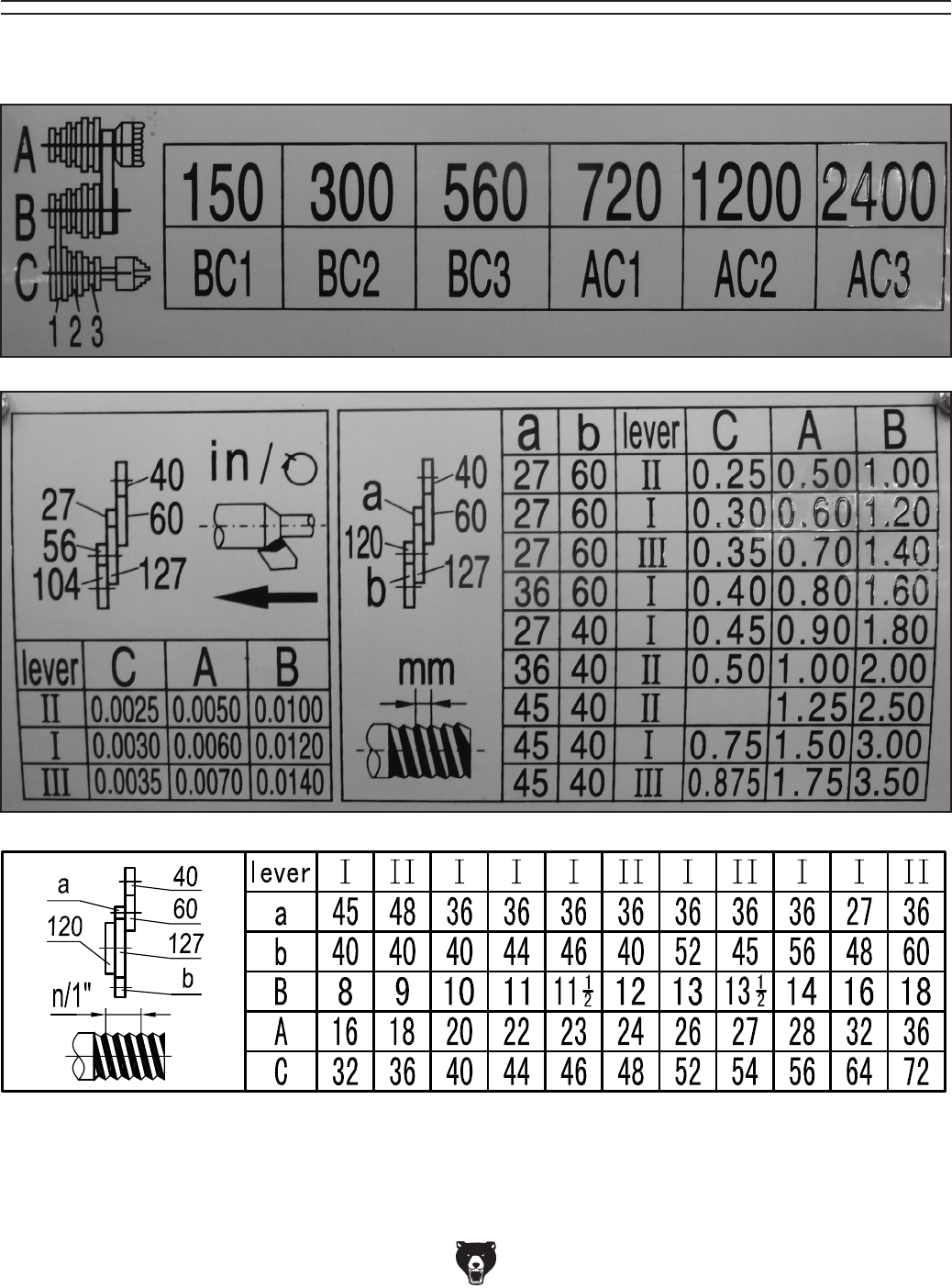
Model G0602/G0752 (Mfg. Since 11/12) -89-
SECTION 10: APPENDIX
machine
G0602 Charts
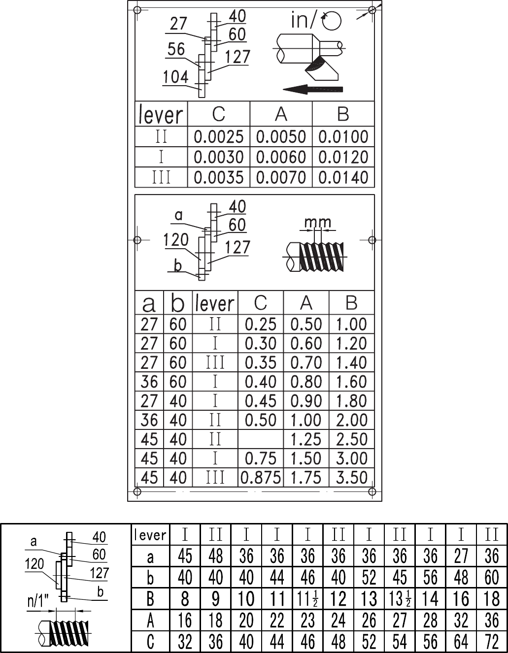
G0752 Charts

CUT ALONG DOTTED LINE
Name _____________________________________________________________________________
Street _____________________________________________________________________________
City _______________________ State _________________________ Zip _____________________
Phone # ____________________ Email _________________________________________________
Model # ____________________ Order # _______________________ Serial # __________________
WARRANTY CARD
The following information is given on a voluntary basis. It will be used for marketing purposes to help us develop
better products and services. Of course, all information is strictly confidential.
1. How did you learn about us?
____ Advertisement ____ Friend ____ Catalog
____ Card Deck ____ Website ____ Other:
2. Which of the following magazines do you subscribe to?
3. What is your annual household income?
____ $20,000-$29,000 ____ $30,000-$39,000 ____ $40,000-$49,000
____ $50,000-$59,000 ____ $60,000-$69,000 ____ $70,000+
4. What is your age group?
____ 20-29 ____ 30-39 ____ 40-49
____ 50-59 ____ 60-69 ____ 70+
5. How long have you been a woodworker/metalworker?
____ 0-2 Years ____ 2-8 Years ____ 8-20 Years ____ 20+ Years
6. How many of your machines or tools are Grizzly?
____ 0-2 ____ 3-5 ____ 6-9 ____ 10+
7. Do you think your machine represents a good value? _____Yes _____No
8. Would you recommend Grizzly Industrial to a friend? _____Yes _____No
9. Would you allow us to use your name as a reference for Grizzly customers in your area?
Note: We never use names more than 3 times. _____Yes _____No
10. Comments: _____________________________________________________________________
_________________________________________________________________________________
_________________________________________________________________________________
_________________________________________________________________________________
____ Cabinetmaker & FDM
____ Family Handyman
____ Hand Loader
____ Handy
____ Home Shop Machinist
____ Journal of Light Cont.
____ Live Steam
____ Model Airplane News
____ Old House Journal
____ Popular Mechanics
____ Popular Science
____ Popular Woodworking
____ Precision Shooter
____ Projects in Metal
____ RC Modeler
____ Rie
____ Shop Notes
____ Shotgun News
____ Today’s Homeowner
____ Wood
____ Wooden Boat
____ Woodshop News
____ Woodsmith
____ Woodwork
____ Woodworker West
____ Woodworker’s Journal
____ Other:

TAPE ALONG EDGES--PLEASE DO NOT STAPLE
FOLD ALONG DOTTED LINE
FOLD ALONG DOTTED LINE
GRIZZLY INDUSTRIAL, INC.
P.O. BOX 2069
BELLINGHAM, WA 98227-2069
Place
Stamp
Here
Name_______________________________
Street_______________________________
City______________State______Zip______
Send a Grizzly Catalog to a friend:

WARRANTY AND RETURNS
Grizzly Industrial, Inc. warrants every product it sells for a period of 1 year to the original purchaser from
the date of purchase. This warranty does not apply to defects due directly or indirectly to misuse, abuse,
negligence, accidents, repairs or alterations or lack of maintenance. This is Grizzly’s sole written warranty
and any and all warranties that may be implied by law, including any merchantability or fitness, for any par-
ticular purpose, are hereby limited to the duration of this written warranty. We do not warrant or represent
that the merchandise complies with the provisions of any law or acts unless the manufacturer so warrants.
In no event shall Grizzly’s liability under this warranty exceed the purchase price paid for the product and
any legal actions brought against Grizzly shall be tried in the State of Washington, County of Whatcom.
We shall in no event be liable for death, injuries to persons or property or for incidental, contingent, special,
or consequential damages arising from the use of our products.
To take advantage of this warranty, contact us by mail or phone and give us all the details. We will then
issue you a “Return Number,’’ which must be clearly posted on the outside as well as the inside of the
carton. We will not accept any item back without this number. Proof of purchase must accompany the
merchandise.
The manufacturers reserve the right to change specifications at any time because they constantly strive to
achieve better quality equipment. We make every effort to ensure that our products meet high quality and
durability standards and we hope you never need to use this warranty.
Please feel free to write or call us if you have any questions about the machine or the manual.
Thank you again for your business and continued support. We hope to serve you again soon.
WARRANTY AND RETURNS