Grizzly G1022SM G1022prozm User Manual To The Fa5ee8cf D6d1 432a Ae81 Cc61fcb97f28
User Manual: Grizzly G1022SM to the manual
Open the PDF directly: View PDF ![]() .
.
Page Count: 84

10" TABLE SAW
INSTRUCTION MANUAL
MODELS G1022SM, G1022Z, G1022ZF, G1022ZFX, G1022PROZ, & G1022PROZX
COPYRIGHT © NOVEMBER, 2002 BY GRIZZLY INDUSTRIAL, INC.
WARNING: NO PORTION OF THIS MANUAL MAY BE REPRODUCED IN ANY SHAPE
OR FORM WITHOUT THE WRITTEN APPROVAL OF GRIZZLY INDUSTRIAL, INC.
PRINTED IN TAIWAN.
ONLINE MANUAL DISCLAIMER
THE INFORMATION IN THIS MANUAL REPRESENTS THE CONFIGURATION OF THE MACHINE AS IT IS CURRENTLY BEING SHIPPED. THE
MACHINE CONFIGURATION CAN CHANGE AS PRODUCT IMPROVEMENTS ARE INCORPORATED. IF YOU OWN AN EARLIER VERSION OF THE
MACHINE, THIS MANUAL MAY NOT EXACTLY DEPICT YOUR MACHINE . CONTACT CUSTOMER SERVICE IF YOU HAVE ANY QUESTIONS
ABOUT DIFFERENCES. PREVIOUS VERSIONS ARE NOT AVAILABLE ONLINE.
G1022ZF
&
G1022ZFX
G1022PROZ
&
G1022PROZX
(Not Shown)
G1022Z
G1022SM

WARNING
Some dust created by power sanding, sawing, grind-
ing, drilling, and other construction activities contains
chemicals known to the State of California to cause
cancer, birth defects or other reproductive harm. Some
examples of these chemicals are:
• Lead from lead-based paints.
• Crystalline silica from bricks, cement, and other
masonry products.
• Arsenic and chromium from chemically treated
lumber.
Your risk from these exposures varies, depending on
how often you do this type of work. To reduce your
exposure to these chemicals: work in a well ventilated
area, and work with approved safety equipment, such
as those dust masks that are specially designed to fil-
ter out microscopic particles.

Table Of Contents PAGE
1. SAFETY
SAFETY RULES FOR ALL TOOLS..........................................................................................................2-3
ADDITIONAL SAFETY INSTRUCTIONS FOR TABLE SAWS....................................................................4
AVOIDING KICKBACK ................................................................................................................................5
SAFETY ACCESSORIES ........................................................................................................................5-6
2. INTRODUCTION
COMMENTARY ........................................................................................................................................7-8
3. CIRCUIT REQUIREMENTS
110V OPERATION ......................................................................................................................................9
220V OPERATION ....................................................................................................................................10
GROUNDING ............................................................................................................................................11
EXTENSION CORD ..................................................................................................................................11
4. MACHINE FEATURES
TERMS AND DEFINITIONS ................................................................................................................12-13
5. SET UP
UNPACKING ..............................................................................................................................................14
PIECE INVENTORY ............................................................................................................................14-15
HARDWARE CONTENTS..........................................................................................................................16
HARDWARE RECOGNITION CHART ......................................................................................................17
CLEAN UP ................................................................................................................................................18
SITE CONSIDERATIONS..........................................................................................................................18
BEGINNING ASSEMBLY ..........................................................................................................................19
STAND ASSEMBLY..............................................................................................................................19-21
HANDWHEELS ..........................................................................................................................................21
MOTOR ................................................................................................................................................22-24
SWITCH ....................................................................................................................................................24
EXTENSION WINGS ................................................................................................................................25
FENCE RAILS............................................................................................................................................26
FENCE ..................................................................................................................................................26-29
BLADE........................................................................................................................................................30
BLADE GUARD ....................................................................................................................................31-32
TABLE INSERT..........................................................................................................................................33
MITER GAUGE ..........................................................................................................................................34
START UP..................................................................................................................................................35
RECOMMENDED ADJUSTMENTS ..........................................................................................................35
6. OPERATIONS
BLADE SELECTION ............................................................................................................................36-37
CROSSCUTTING ......................................................................................................................................38
RIPPING ....................................................................................................................................................39
DADO CUTTING ..................................................................................................................................40-42
RABBET CUTTING ..............................................................................................................................42-45
7. MAINTENANCE
GENERAL ..................................................................................................................................................46
LUBRICATION ..........................................................................................................................................47
TABLE ........................................................................................................................................................47
V-BELT ......................................................................................................................................................47
MAINTENANCE LOG ................................................................................................................................48
8. SERVICE ADJUSTMENTS
BLADE PARALLELISM ........................................................................................................................49-51
45˚ & 90˚ STOPS ......................................................................................................................................52
9. CLOSURE
WIRING DIAGRAMS ............................................................................................................................54-55
PART DRAWINGS & LISTS ................................................................................................................56-73
TROUBLESHOOTING ..............................................................................................................................74
PUSHSTICK LAYOUT ..............................................................................................................................75

-2- G1022 Series Table Saws
SECTION 1: SAFETY
For Your Own Safety Read Instruction
Manual Before Operating This Equipment
Indicates an imminently hazardous situation which, if not avoided,
WILL result in death or serious injury.
Indicates a potentially hazardous situation which, if not avoided,
COULD result in death or serious injury.
Indicates a potentially hazardous situation which, if not avoided,
MAY result in minor or moderate injury, or MAY cause property
damage.
This symbol is used to alert the user to useful information about
proper operation of the equipment.
The purpose of safety symbols is to attract your attention to possible hazardous conditions. This
manual uses a series of symbols and signal words which are intended to convey the level of
importance of the safety messages. The progression of symbols is described below. Remember
that safety messages by themselves do not eliminate danger and are not a substitute for proper
accident prevention measures.
NOTICE
Safety Instructions For Power Tools
5. KEEP CHILDREN AND VISITORS
AWAY. All children and visitors should be
kept at a safe distance from work area.
6. MAKE WORKSHOP CHILD PROOF with
padlocks, master switches, or by removing
starter keys.
7. DO NOT FORCE TOOL. It will do the job
better and safer at the rate for which it was
designed.
8. USE RIGHT TOOL. Do not force tool or
attachment to do a job for which it was not
designed.
1. KEEP GUARDS IN PLACE and in working
order.
2. REMOVE ADJUSTING KEYS AND
WRENCHES. Form habit of checking to
see that keys and adjusting wrenches are
removed from tool before turning on.
3. KEEP WORK AREA CLEAN. Cluttered
areas and benches invite accidents.
4. DO NOT USE IN DANGEROUS ENVI-
RONMENT. Do not use power tools in
damp or wet locations, or where any flam-
mable or noxious fumes may exist. Keep
work area well lighted.
G1022 Series Table Saws -3-
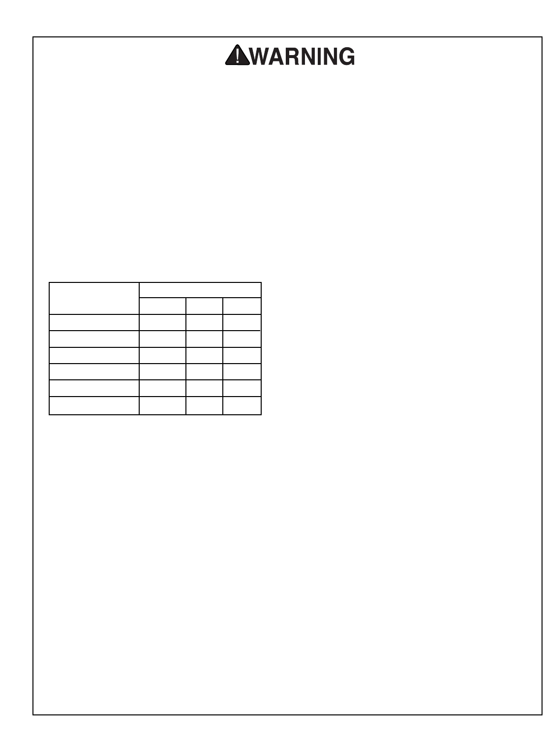
9. USE PROPER EXTENSION CORD. Make
sure your extension cord is in good condi-
tion. Conductor size must be in accor-
dance with the chart below. The amperage
rating is listed on the motor or tool name-
plate. An undersized cord will cause a drop
in line voltage resulting in loss of power
and overheating. Your extension cord must
also contain a ground wire and plug pin.
Always repair or replace damaged exten-
sion cords.
Minimum Gauge for Extension Cords
10. WEAR PROPER APPAREL. Do not wear
loose clothing, gloves, neckties, rings,
bracelets, or other jewelry which may get
caught in moving parts. Non-slip footwear
is recommended. Wear protective hair cov-
ering to contain long hair.
11. ALWAYS USE ANSI-APPROVED SAFE-
TY GLASSES. Also use face or dust mask
if cutting operation is dusty. Everyday eye-
glasses only have impact resistant lenses,
they are NOT safety glasses.
12. SECURE WORK. Use clamps or a vise to
hold work when practical. It is safer than
using your hand and frees both hands to
operate tool.
13. NEVER OVERREACH. Keep proper foot-
ing and balance at all times.
LENGTH
AMP RATING 25ft 50ft 100ft
0-6 18 16 16
7-10 18 16 14
11-12 16 16 14
13-16 14 12 12
17-20 12 12 10
21-30 10 10 No
Safety Instructions For Power Tools
14. MAINTAIN TOOLS WITH CARE. Keep
tools sharp and clean for best and safest
performance. Follow instructions for lubri-
cating and changing accessories.
15. DISCONNECT TOOLS before servicing
and changing accessories, such as blades,
bits, cutters, and any other item.
16. REDUCE THE RISK OF UNINTENTION-
AL STARTING. Make sure switch is in off
position before plugging in. Also, the mag-
netic switch on this machine may start if the
switch gets bumped hard enough.
17. USE RECOMMENDED ACCESSORIES.
Consult the owner’s manual for recom-
mended accessories. The use of improper
accessories may cause risk of injury.
18. CHECK DAMAGED PARTS. Before fur-
ther use of the tool, a guard or other part
that is damaged should be carefully
checked to determine that it will operate
properly and perform its intended function.
Check for alignment of moving parts, bind-
ing of moving parts, breakage of parts,
mounting, and any other conditions that
may affect its operation. A guard or other
part that is damaged must be properly
repaired or replaced.
19. NEVER LEAVE TOOL RUNNING UNAT-
TENDED. TURN POWER OFF. Do not
leave tool until it comes to a complete stop.
20. NEVER USE UNDER THE INFLUENCE of
alcohol or drugs, or when tired.
21. IF AT ANY TIME YOU ARE EXPERI-
ENCING DIFFICULTIES performing the
intended operation, stop using the
machine! Then contact our service depart-
ment or ask a qualified expert how the
operation should be performed.
-4- G1022 Series Table Saws
Additional Safety Instructions For Table Saws
1. THRU-SAWING: Use blade guard, splitter,
and anti-kickback fingers on all thru-saw-
ing operations. See Page 12 for the defin-
ition of thru-sawing.
2. KICKBACK: Use anti-kickback devices
during ALL cutting operations. If you do not
have a complete understanding of how
kickback occurs, or how to prevent it, Do
not operate this table saw. See Page 12
for the definition of kickback.
3. DANGEROUS REACHING: Do not reach
behind or over the saw blade with either
hand while the saw is running.
4. PUSHSTICK: Use a push stick when rip-
ping narrow stock.
5. FREE-HAND CUTTING: The fence or the
miter gauge must support the workpiece
during all cutting operations.
6. BODY POSITION WHEN CUTTING: Do
not stand or have any part of your body in-
line with the path of the saw blade.
7. WORKPIECE CONTROL: Hold the work-
piece firmly against the miter gauge or
fence and hold the workpiece firmly
against the table.
8. CROSSCUTTING: Move the rip fence out
of the way when crosscutting.
9. MITER GAUGE/RIP FENCE: Never use
the miter gauge and rip fence at the same
time.
10. STALLED BLADE: Never attempt to free a
stalled saw blade without first turning the
saw off.
11. CUTOFF TABLES: Use adequate support
to the rear and sides of the saw table for
wide or long workpieces.
12. HAND SAFETY: Avoid awkward cutting
operations and hand positions where a
sudden slip could cause your hand to move
into the saw blade.
13. SAW BLADE: Lower the saw blade below
the table when not in use.
14. DAMAGED SAW BLADE: Never use a
damaged saw blade or one that has been
dropped.
15. DADO CUTTING: There is a high degree
of risk involved with any dado operation.
See Page 12 for the definition of dado.
No list of safety guidelines can be com-
plete. Operating this machinery may
require additional safety precautions spe-
cific to your shop environment. Failure to
use reasonable caution while operating
this machine could result in serious per-
sonal injury.
Unfamiliarity with this manual could result
in serious personal injury. Become familiar
with the contents of this manual, including
all the safety warnings.
G1022 Series Table Saws -5-
Push Sticks
The use of push sticks, particularly when cutting
small or narrow workpieces, provides a double
benefit for saw operators. The push stick pro-
vides added leverage, enabling the operator to
keep the workpiece firmly supported against the
fence and table. At the same time, the push stick
keeps the operator’s hand safely away from the
rotation of the saw blade as shown in Figure 1.
See the template on Page 76 of the manual for
construction details, or purchase one from the
Grizzly catalog or website.
Safety Accessories
Not using safety accessories could cause
serious personal injury. Learn how to cor-
rectly use each safety accessory.
Figure 1. Push Stick.
Push Stick
Statistics prove that most common accidents
among table saw users can be linked to kick-
back.
Kickback is typically defined as the high-speed
expulsion of stock from the table saw toward its
operator.
In addition to the danger of the operator or oth-
ers in the area being struck by the flying stock, it
is often the case that the operator’s hands are
forced into the blade during the kickback.
The following can help minimize kickbacks:
•Use your blade guard and splitter.
•Never for any reason place your hand behind
the blade. Should kickback occur, your hand
will be pulled into the blade.
•Inspect splitter for alignment between it and
your blade.
•Never use the fence as a guide for crosscut-
ting.
•Never attempt freehand cuts.
•Use a push stick or featherboard to maintain
control of your workpiece.
•Feed cuts through to completion.
•Stand to the side when ripping.
•Ensure your fence and miter slot are parallel to
the blade.
If you do not have a clear understanding of kick-
back and how it occurs, do not operate this table
saw.
Failure to understand how and why kick-
back occurs could cause serious person-
al injury. DO NOT operate this table saw if
you do not have a clear understanding of
kickback, and how it occurs.
Avoiding Kickback
-6- G1022 Series Table Saws
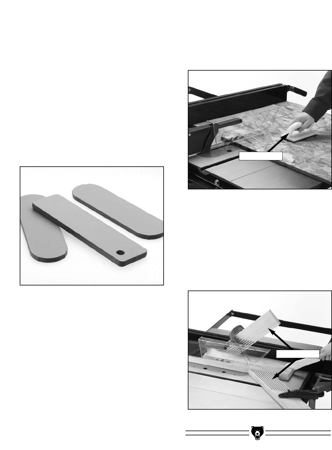
Figure 2. Zero Clearance Table Inserts.
Zero Clearance Table Inserts
Ideal for use when ripping thin strips or making
bevel cuts, these prevent tearout and jammed
blades by supporting material close to the blade.
Use the standard table insert as a template when
creating additional inserts from wood or plywood.
Slots can be custom cut for specific blade angles
by raising the running blade into an uncut insert
at the angle you desire. Be sure to make an addi-
tional slot for the blade splitter.
We also carry a wide selection of table inserts
(Figure 2) in the Grizzly catalog or website. Be
sure to hold the insert firmly in place with a piece
of wood when creating slots. Never hold the table
insert with your hand while cutting new slots.
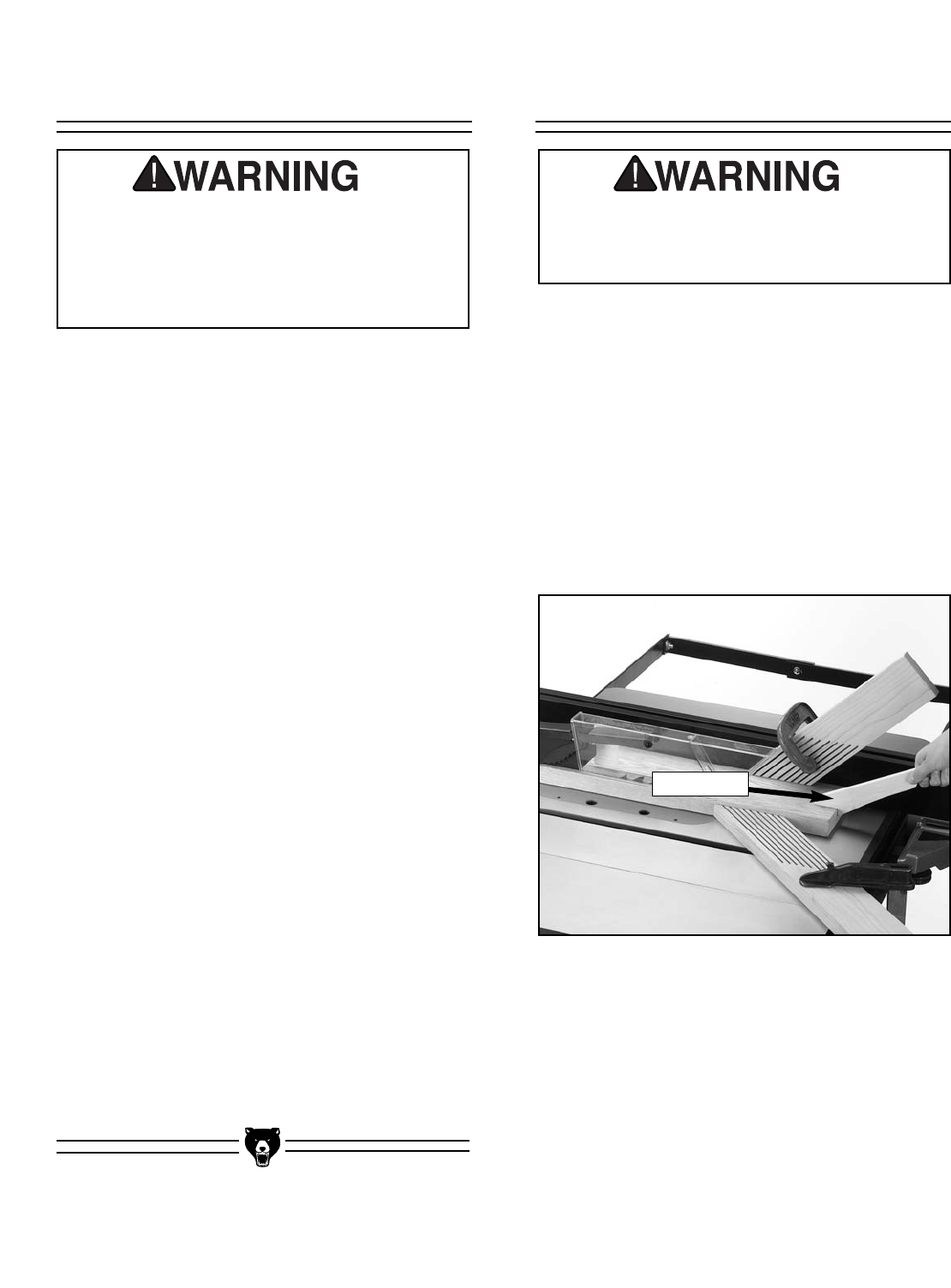
Push Paddles
Push paddles provide added leverage and sup-
port when ripping or crosscutting wide work-
pieces as shown in Figure 3. We offer a number
of push paddles in the Grizzly catalog.
Featherboards
Easily made from scrap stock, featherboards pro-
vide an added degree of protection against kick-
back as shown in Figure 4. To make a feather-
board, cut a 30-40° angle at one end of the board
and make a number of end cuts at approximately
1⁄4" apart and 2" to 3" deep. We also offer a num-
ber of featherboards in the Grizzly catalog.
Figure 3. Push Paddles.
Figure 4. Featherboards.
Push Paddles
Featherboards

G1022 Series Table Saws -7-
SECTION 2: INTRODUCTION
Grizzly is proud to offer the Model G1022 Series
Table Saws. The Model G1022 Series Table
Saws are part of a growing Grizzly family of fine
woodworking machinery. When used according to
the guidelines set forth in this manual, you can
expect years of trouble-free, enjoyable operation
and proof of Grizzly’s commitment to customer
satisfaction.
The Model G1022 Series Table Saws come in 6
different versions. The differences are listed on
the chart above. They are all 10" heavy-duty table
saws designed for a wide variety of cutting appli-
cations. They feature ball bearing arbors on a
worm gear mechanism, precision-ground cast
iron tables (except the Model SM), sturdy steel
stands, standard and dado inserts, and a miter
gauge.
Grizzly offers many accessories for the table
saws including blades, extension rails, outfeed
rollers and mobile bases. Please refer to the cur-
rent Grizzly catalog or website for prices and
ordering information.
Grizzly is also pleased to provide this manual with
the Model G1022 Series Table Saws. It was writ-
ten to guide you through assembly, review safety
considerations, and cover general operating pro-
cedures. If you have any comments regarding this
manual, please write to us at the address below:
Grizzly Industrial, Inc.
C/O Technical Documentation
P.O. Box 2069
Bellingham, WA 98227-2069
Commentary
Features SM Z ZF ZFX PROZ PROZX
Versions
G1022
Extension
Wings
Rip Fence
Miter Gauge
Motor
Pre-Wired
Switch
Weight
Dust Port
Sheet Metal
Standard
Standard
1.5 HP-110/220V
110V
Body Mounted
220 lbs
-
Solid Cast Iron
SHOP FOX®Classic
Adjustable Slot
2HP-110/220V
220V
Rail Mounted
340 lbs
4" Port
Solid Cast Iron
SHOP FOX®Heavy-Duty
Adjustable Slot
2HP-110/220V
220V
Rail Mounted
340 lbs
4" Port
Slotted Cast Iron
T-Slot Fence
Standard
1.5 HP-110/220V
110V
Body Mounted
250 lbs
-
Slotted Cast Iron
SHOP FOX®Heavy-Duty
Adjustable Slot
1.5 HP-110/220V
110V
Rail Mounted
290 lbs
4" Port
Slotted Cast Iron
SHOP FOX®Heavy-Duty
Adjustable Slot
2 HP-110/220V
220V
Rail Mounted
290 lbs
4" Port

-8- G1022 Series Table Saws
Most importantly, we stand behind our machines.
If you have any service questions or parts
requests, please call or write us at the location
listed below:
Grizzly Industrial, Inc.
1203 Lycoming Mall Circle
Muncy, PA 17756
Phone: (570) 546-9663
Fax: (800) 438-5901
E-Mail: techsupport@grizzly.com
Web Site: http://www.grizzly.com
The specifications, drawings, and photographs
illustrated in this manual represent the Model
G1022 Series Table Saws as supplied when the
manual was prepared. However, owing to
Grizzly’s policy of continuous improvement,
changes may be made at any time with no oblig-
ation on the part of Grizzly. Current Grizzly
machine manuals can be viewed and printed at:
www.grizzly.com.
Lack of familiarity with
this manual could
cause serious person-
al injury. Become
familiar with the con-
tents of this manual,
including all the safety
warnings.
G1022 Series Table Saws -9-
SECTION 3: CIRCUIT REQUIREMENTS
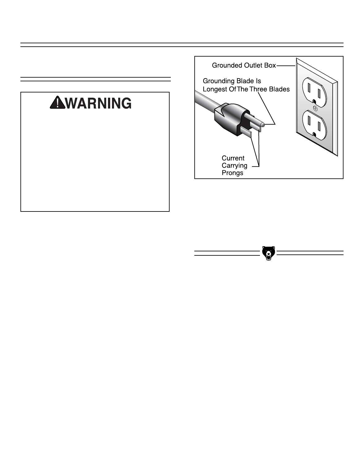
110V Operation
The Models SM, Z & ZF motors are prewired to
operate at 110V. See Figure 5 for a typical 110V
plug and outlet.
Models SM & Z:
Under normal 110V use, the Models SM & Z
motors draw approximately 16 amps. Use a 20
amp circuit breaker or a 20 amp slow-blow fuse.
Model ZF:
Under normal 110V use, the Model ZF motor
draws approximately 17 amps. Use a 20 amp cir-
cuit breaker or a 20 amp slow-blow fuse.
If the machine is not wired correctly a fire
could result. Make sure your wiring, recep-
tacle, plug, and circuit breaker can handle
the current draw of the machine. If you are
not sure that your electrical circuit can han-
dle the current draw, get a qualified electri-
cian to test your electrical system and do
any required upgrades. Do not attempt to
modify an existing circuit by only replacing
the circuit breaker with one rated for a high-
er amperage draw than the wiring, recepta-
cle, and plug are rated for. The circuit you use should be dedicated, (i.e., the
machine should provide the only draw from that
circuit). If frequent circuit failures occur when
using this machine, contact our Service
Department or your local electrical contractor.
Figure 5. Typical 110V 3-prong plug and outlet.
-10- G1022 Series Table Saws
220V Operation
The circuit you use should be dedicated, (i.e., the
machine should provide the only draw from that
circuit). If frequent circuit failures occur when
using this machine, contact our Service
Department or your local electrical contractor.
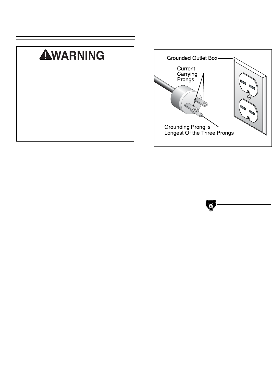
The Models ZFX, PROZ, & PROZX do not come
with a plug. When operating at 220V, use a
NEMA-style 6-15 plug and receptacle as shown in
Figure 6.
The motors supplied with the Models ZFX, PROZ,
& PROZX are prewired to operate at 220V.
Models ZFX, PROZ, & PROZX:
Under normal 220V use, the motor draws approx-
imately 13 amps. Use a 15 amp circuit breaker or
a 15 amp slow-blow fuse for 220V operation.
Figure 6. NEMA-style 6-15 plug and receptacle.
If the machine is not wired correctly a fire
could result. Make sure your wiring, recep-
tacle, plug, and circuit breaker can handle
the current draw of the machine. If you are
not sure that your electrical circuit can han-
dle the current draw, get a qualified electri-
cian to test your electrical system and do
any required upgrades. Do not attempt to
modify an existing circuit by only replacing
the circuit breaker with one rated for a high-
er amperage draw than the wiring, recepta-
cle, and plug are rated for.

G1022 Series Table Saws -11-
Grounding
Extension Cord
In the event of an electrical short, grounding pro-
vides electric current a path of least resistance to
reduce the risk of electrical shock to the operator.
Ground the power cord and this machine in accor-
dance with all local codes and ordinances.
Operating the machine when it is not properly
grounded can result in electric shock or electro-
cution.
Should it be necessary to use an extension make
sure the cord is rated Hard Service (grade S) or
better. Refer to the chart in Section 1: Safety
Instructions to determine the minimum gauge for
the extension cord. The extension cord must also
contain a ground wire and plug pin. Always repair
or replace extension cords when they become
worn or damaged.
Electrocution or a fire
could result if the table
saw is not grounded cor-
rectly. Make sure all
electrical circuits are
grounded. DO NOT use
the machine if it is not
grounded.
NOTICE
The wire on the power cord with green or
green and yellow striped insulation is the
grounding conductor.
No single list of electrical guidelines can
be comprehensive for all shop environ-
ments. Operating this machinery may
require additional electrical upgrades spe-
cific to your machine and shop environ-
ment. It is your responsibility to make sure
your electrical systems comply with all
local electrical codes and ordinances.

-12- G1022 Series Table Saws
SECTION 4: MACHINE FEATURES
The following is a list of common definitions,
terms and phrases used throughout this manual
as they relate to this table saw and woodworking
in general. It is important that you read and
become familiar with them before assembling,
adjusting or operating this machine. Your safety
is VERY important to us at Grizzly!
Arbor: Metal shaft extending from the drive
mechanism, to which the cutting blade is
attached.
Bevel Edge Cut: Tilting the saw arbor and blade
to an angle between 0° and 45° to perform an
angled cutting operation.
Blade Guard: Metal or plastic mechanism that
mounts over the saw blade to prevent acciden-
tal contact with the cutting edge.
Crosscut: Table saw operation in which the miter
gauge is used to cut across the grain of a piece
of wood.
Dado Blade: Blade or set of blades that attach to
the arbor and are used for cutting grooves and
rabbets.
Dado Cut: Table saw operation that uses a dado
blade to cut a flat bottomed groove into the
face of wood stock.
Featherboard: Safety device used to keep the
workpiece against the rip fence or table during
a cutting operation. The featherboard also
allows the operator to keep his/her hands at a
safe distance away from the saw blade while
cutting the workpiece.
Terms and Definitions Kerf: The resulting cut or gap made by a saw
blade.
Kickback: A condition in which the wood is
thrown back towards an operator at a high rate
of speed.
Miter Gauge: A component that controls the
wood stock movement while performing a
crosscut. Allows for variation of angle cuts
such as miter cuts used on a picture frame.
Moulding Head: A cutterhead attached to the
arbor that accepts interchangeable moulding
knives for profile cutting. We DO NOT recom-
mend the use of moulding head cutters.
Parallel: Being an equal distance apart at every
point. i.e. the rip fence face is parallel to the
side face of the saw blade.
Non-Thru Cut: A sawing operation that requires
the removal of the blade guard and splitter.
Dado and rabbet cuts are considered Non-
Thru Cuts because the blade does not pro-
trude above the top face of the wood stock.
Always remember to reinstall the blade guard
and splitter after performing a non-thru cut.
Perpendicular: Intersecting and forming right
angles; at right angles to the vertical and hori-
zontal planes. i.e. the blade is perpendicular to
the table surface.
Push Paddle: Safety aid used to push a piece of
wood stock through a cutting operation.
Push Stick: Safety aid used to push a piece of
wood stock through a cutting operation.
Usually used when rip cutting.
Rabbet: Cutting operation that creates an L-

G1022 Series Table Saws -13-
shaped channel along the edge of wood stock.
Splitter: Metal plate attached to the back of the
blade guard that maintains the kerf opening in
the wood when performing a cutting operation.
Standard Kerf: 1⁄8" gap made with a standard
blade.
Straightedge: A tool used to check the flatness,
parallelness, or consistency of a surface(s).
Thru-Sawing: A sawing operation where the
wood stock thickness is completely sawn
through. Proper blade height usually allows 1⁄4"
of the top of the blade to extend above the
wood stock.
Thin Kerf: 3⁄32" gap made with a thin kerf blade.
Rip Cut: A cut made along the grain of the wood.
Sacrificial Fence: A piece of wood attached to
the face of the rip fence that is designed to
extend the fence face away from the metal por-
tion of the fence. Used primarily when making
rabbet cuts with a dado blade.
Main Features
C
B
D
A
H
E
F
G
I
Figure 7. The front of the table saw.
(Model SM Shown)
A. Extension Wing
B. On/Off Switch
C. Blade Angle Handwheel
D. Stand
E. Blade Height Handwheel
F. Rip Fence Rails
G. Rip Fence
H. Blade Guard/Splitter Assembly
I. Miter Gauge
Set up and operation instructions will be easier to
understand if you become familiar with the loca-
tion and names of the basic features.
Match up the feature list below with the letters in
Figure 7 to identify the table saw feature loca-
tions.

-14- G1022 Series Table Saws
Unpacking
The Model G1022 Series Table Saws are
shipped from the manufacturer in carefully
packed cartons. If you discover the machine is
damaged after you have signed for delivery,
immediately call our Customer Service for advice.
When you are completely satisfied with the con-
dition of your shipment, you should inventory its
parts.
Piece Inventory
The Model G1022 Series
is a heavy machine,
weighing up to 340 lbs.
Personal injury could
occur if the machine is
moved without addition-
al assistance. Seek the
assistance of other peo-
ple when moving or lift-
ing the machine.
SECTION 5: SET UP
Sharp edges on metal
parts may cause person-
al injury. Examine the
edges of all metal parts
before handling.

G1022 Series Table Saws -15-
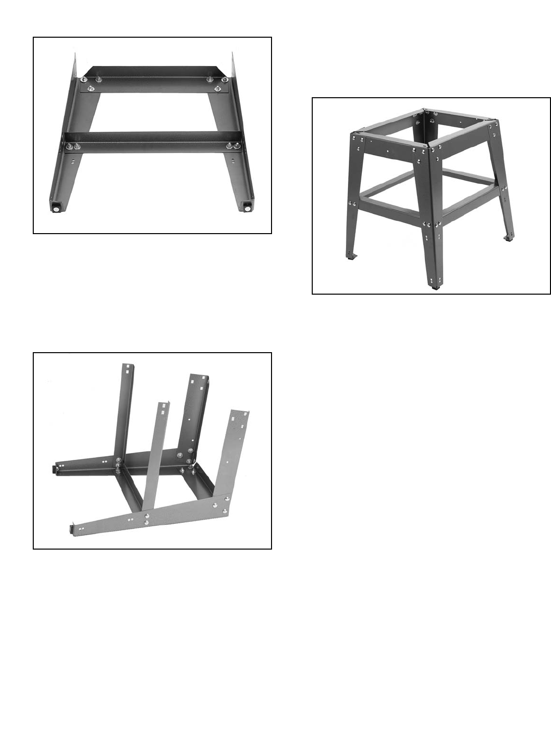
Figure 8. Rip fence, rails and extension wings will vary depending on the model.
9. Motor with Pulley
10. Miter Gauge
11. Dado Insert
12. Standard Insert
13. Arbor Wrench
14. Blade Guard Bracket
15. Table Saw Unit
16. Stand Components
17. Handwheels (2)
18. Motor Mount Plate
19. V-Belt
1. Fence Unit (Separate Box with Models ZF, ZFX,
PROZ, & PROZX)
2. Extension Wings (2)
- Model SM: Sheet Metal
- Models Z, ZF, & ZFX: Slotted Cast Iron
- Models PROZ & PROZX: Solid Cast Iron
3. Fence Rails (Separate Box)
4. Hardware Bags (5)
5. Blade Guard
6. V-Belt Guard and Mounting Hardware
7. Motor Bracket
8. V-Belt Guard Bracket
After all the parts have been removed from the carton, you should have:
3
1
2
17
8
9
10
11
12
13
14 19
18
6
5
4
7
15
16
-16- G1022 Series Table Saws
Qty Description
8Special Rail Bolt (SM & Z)
8Fence Rail Spacer (SM & Z)
4Flat Washer M10 (SM & Z)
4Hex Nut M10-1.5 (SM & Z)
4Fence Rail Plug (SM & Z)
6Flat Washer M10 x M4 Thick
6Hex Bolt M10-1.5 x 25
2Hand Wheel Knob
Guide Rail & Extension Wing Hardware Bag
Qty Description
40 Carriage Bolt M8-1.25 x 16
4Hex Bolt M8-1.25 x 19
48 Flat Washer M8
44 Hex Nut M8-1.25
4Hex Bolt M10-1.5 x 20
4Hex Nut M10-1.5
4Flat Washer M10
4Plastic Foot
4Hex Bolt #10-24 x 3⁄8" (ZX, ZFX, PROZ, PROZX)
4Hex Nut #10-24 (ZX, ZFX, PROZ, PROZX)
4Lock Washer #10 (ZX, ZFX, PROZ, PROZX)
Floor Stand Hardware Bag
Hardware Contents
Qty Description
1Hex Bolt 1⁄4"-20 x 2"
1Flat Washer 1⁄4"
1Sleeve
1Wing Nut 1⁄4"-20
1Plastic Belt Guard
Plastic Belt Guard Hardware Bag
Qty Description
4Hex Bolt M8-1.25 x 25
8Flat Washer M8
4Hex Nut M8-1.25
Motor Mount Hardware Bag
G1022 Series Table Saws -17-
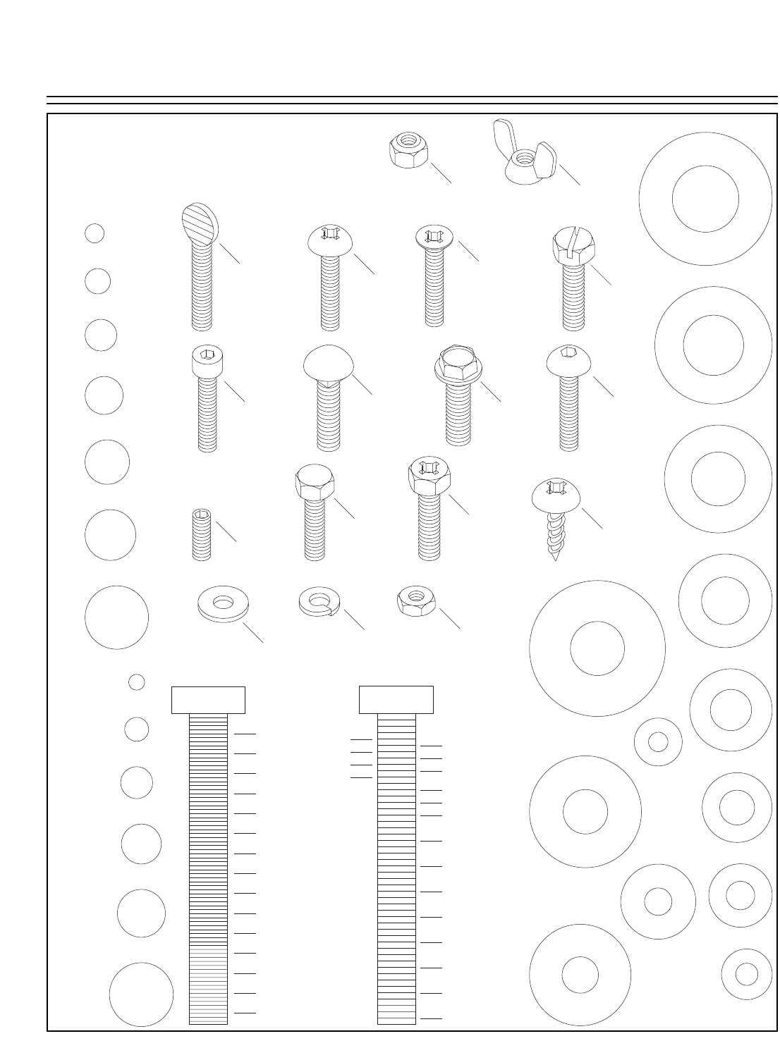
Hardware Recognition Chart
5mm
10mm
15mm
20mm
25mm
30mm
35mm
40mm
45mm
50mm
55mm
60mm
65mm
70mm
75mm
Washer Lock
Washer
Hex
Nut
Wing
Nut
Phillips
Head
Sheet
Metal
Screw
Setscrew
Phillips
Head
Screw
Thumb
Screw Slotted
Screw
Countersunk
Phillips
Head
Screw
Cap
Screw
Carriage
Bolt
Hex
Head
Bolt
Button
Head
Screw
Flange
Bolt
Phillips
Head
Hex
Bolt
Lock
Nut
5⁄16''
1⁄4''
3⁄8''
1⁄2''
5⁄8''
7⁄16''
9⁄16''
3⁄4''
7⁄8''
1''
11⁄4''
11⁄2''
13⁄4''
2
21⁄4''
21⁄2''
23⁄4''
3
LINES ARE 1MM APART
LINES ARE 1⁄16'' INCH APART
5⁄8''
W
A
S
H
E
R
D
I
A
M
E
T
E
R
9⁄16''
W
A
S
H
E
R
D
I
A
M
E
T
E
R
1⁄2''
W
A
S
H
E
R
D
I
A
M
E
T
E
R
12mm
W
A
S
H
E
R
D
I
A
M
E
T
E
R
10mm
W
A
S
H
E
R
D
I
A
M
E
T
E
R
7⁄16''
W
A
S
H
E
R
D
I
A
M
E
T
E
R
8mm
W
A
S
H
E
R
D
I
A
M
E
T
E
R
3⁄8''
W
A
S
H
E
R
D
I
A
M
E
T
E
R
5⁄16''
W
A
S
H
E
R
D
I
A
M
E
T
E
R
1⁄4''
W
A
S
H
E
R
D
I
A
M
E
T
E
R
#10
W
A
S
H
E
R
D
I
A
M
E
T
E
R
4mm
W
A
S
H
E
R
D
I
A
M
E
T
E
R
6mm
W
A
S
H
E
R
D
I
A
M
E
T
E
R
WASHERS ARE MEASURED BY THE INSIDE DIAMETER
MEASURE BOLT DIAMETER BY PLACING INSIDE CIRCLE
#10
1⁄4''
5⁄16''
3⁄8''
7⁄16''
1⁄2''
5⁄8''
4mm
6mm
8mm
10mm
12mm
16mm
Use this chart to match up
hardware pieces during the
assembly process!
-18- G1022 Series Contractor Saws
Clean Up Site Considerations
Unsupervised children
and visitors entering a
shop could receive seri-
ous personal injury.
Ensure child and visitors
safety by keeping all
entrances to the shop
locked at all times. DO
NOT allow unsupervised
children or visitors in the
shop at any time.
The unpainted surfaces are coated with a waxy
oil to protect them from corrosion during ship-
ment. Remove this waxy oil with a solvent clean-
er or citrus-based degreaser such as Grizzly’s
G7895 Degreaser. To clean thoroughly, some
parts may need to be removed. The machine
will operate best when the waxy oil is
removed from all moving and sliding parts.
Chlorine-based cleaners and solvents will dam-
age the painted surfaces of the machine. Follow
the manufacturer’s instructions when using any
type of cleaning product.
Gasoline or petroleum
products used to clean
the machinery could
explode causing serious
personal injury. DO NOT
use gasoline or petrole-
um products to clean the
machinery.
Smoking near solvents
could ignite an explosion
or fire causing serious per-
sonal injury. Do not smoke
while using solvents.
Lack of ventilation while
using solvents could
cause serious personal
health risks, fire, or
environmental hazards.
Always work in a well
ventilated areas to pre-
vent the accumulation
of dangerous fumes.
Supply the work area
with a constant supply
of fresh air using a fan.
Floor Load
The Model G1022 Series Table Saws are a heavy
load with a medium footprint. Most commercial or
home shop floors should be sufficient to carry the
weight of the machine. Reinforce the floor if you
question its ability to support the weight.
Working Clearance
Working clearances can be thought of as the dis-
tances between machines and obstacles that
allow safe operation of every machine without lim-
itation. Consider existing and anticipated machine
needs, size of material to be processed through
each machine, and space for auxiliary stands or
work tables. Also, consider the relative position of
each machine to one another for efficient materi-
al handling. Be sure to allow yourself sufficient
room to safely run your machines in any foresee-
able operation and keep dust collection hoses off
the floor and out of the way.
Lighting
Lighting should be bright enough to eliminate
shadows and prevent eye strain. Electrical circuits
should be dedicated or large enough to handle
combined motor amp loads. Be sure to follow
local electrical codes for proper installation of new
lighting or circuits.
G1022 Series Table Saws -19-
Beginning Assembly Stand Assembly
TOOLS REQUIRED: High quality square and
straightedge, metric Allen wrench set, flat screw-
driver, Phillips screwdriver, dead blow hammer
and a 6" or 8" adjustable wrench.
Loose hair and clothing
could get caught in
machinery causing seri-
ous personal injury.
Keep loose clothing
rolled up and long hair
tied up and away from
machinery.
Projectiles thrown from
the machine could cause
serious eye injury. Wear
safety glasses during
assembly.
Figure 9. Installing the rubber feet.
To assemble the stand:
1. Fasten the rubber feet to the leg bottoms
using M10-1.5 x 25 hex bolts, 10MM flat
washers and M10-1.5 hex nuts as shown in
Figure 9.
2. Bolt the long upper and lower side braces (2
each) to the legs using M8-1.25 x 16 car-
riage bolts, 8MM flat washers and M8-1.25
hex nuts as shown in Figure 10.Do not com-
pletely tighten the hex bolts at this time.
Examine the edges of all
metal parts before han-
dling. Sharp edges on
metal parts may cause
personal injury.
Disconnect the machine
power cord during
assembly. Failure to fol-
low this warning could
result in serious person-
al injury or death.
!
-20- G1022 Series Table Saws
Figure 11. Short upper and lower braces
attached to one of the stand assemblies.
3. Attach the short upper and lower side braces
(2 each) to one of the assembled side pan-
els using M8 - 1.25 x 16 carriage bolts, 8MM
flat washers and M8-1.25 hex nuts as shown
in Figure 11.
4. Bolt the stand assemblies together using
M8-1.25 x 16 carriage bolts, 8MM flat wash-
ers and M8-1.25 hex nuts as shown in
Figure 12.
Models ZF, ZFX, PRO, & PROZX only:
5. Align the bolt holes on the dust hood with the
bolt holes on the dust hood adapter.
6. Secure the dust hood and the dust adapter
together using 10-24 x 3⁄8" bolts, 10-24 nuts
and 3⁄16" lock washers.
7. Turn the table saw body upside-down.
8. Place the dust hood assembly over the bot-
tom of the table saw body with the dust hood
flange pointed up.
Figure 12. Stand completely assembled.
Figure 10. Long upper and lower braces
attached to the stand legs.
G1022 Series Table Saws -21-
All Models:
8. Place the assembled stand upside down on
the table saw body and align all the mounting
holes. Make certain the side of the stand with
the “Z Series” label, if applicable, is on the
front side of the machine (the side with the
Grizzly label and angle scale).
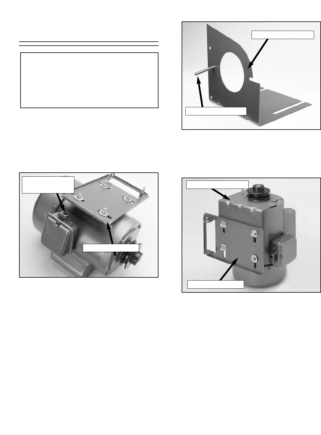
9. Secure the stand to the body using M8-1.25
x 19 hex bolts, 8MM flat washers and M8-
1.25 hex nuts, with the dust port sandwiched
between on the Models ZF, ZFX, PROZ, &
PROZX, as shown in Figure 13.
Figure 13. Attaching the stand to the saw base.
10. With the help of a second person, flip the
entire table saw unit right side-up and move
it into its working position.
11. Tighten all of the stand bolts.
Saw Body
Stand
Dust Hood
(ZF, ZFX, PROZ,
& PROZX Only)
Dust Hood Adapter
(ZF, ZFX, PROZ, &
PROZX Only)
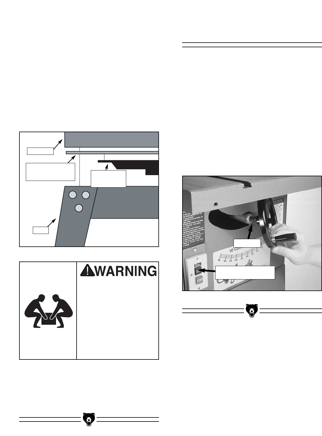
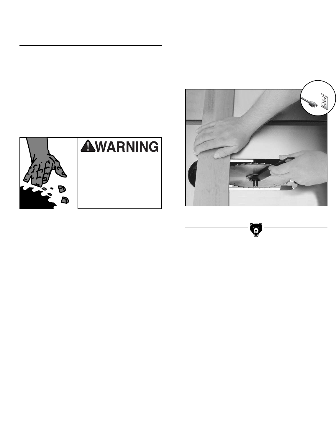
Figure 14. Mounting the handwheels.
To mount the handwheels:
1. Position one of the handwheels over the
arbor lifting shaft on the front of the saw.
2. The slots in the handwheel hole will engage
with the roll pin on the shaft as shown in
Figure 14.
3. Position the other handwheel on the blade
tilting shaft located on the side of the saw.
4. Screw the black plastic lock knobs onto the
ends of the shafts to lock the handwheels in
place.
Handwheels
Roll Pin
Body mounted switch on
Models SM & Z only
The Model G1022 Series
is a heavy machine,
weighing up to 340 lbs.
Personal injury could
occur if the machine is
moved without addition-
al assistance. Seek the
assistance of other peo-
ple when moving or lift-
ing the machine.
-22- G1022 Series Table Saws
3. Set the motor on end and slip the pulley
guard bracket between the base of the motor
and the motor plate as shown in Figure 17.
Figure 17. Installing pulley guard.
4. Tighten 1 of the 4 mounting bolts. Leave the
other 3 loose.
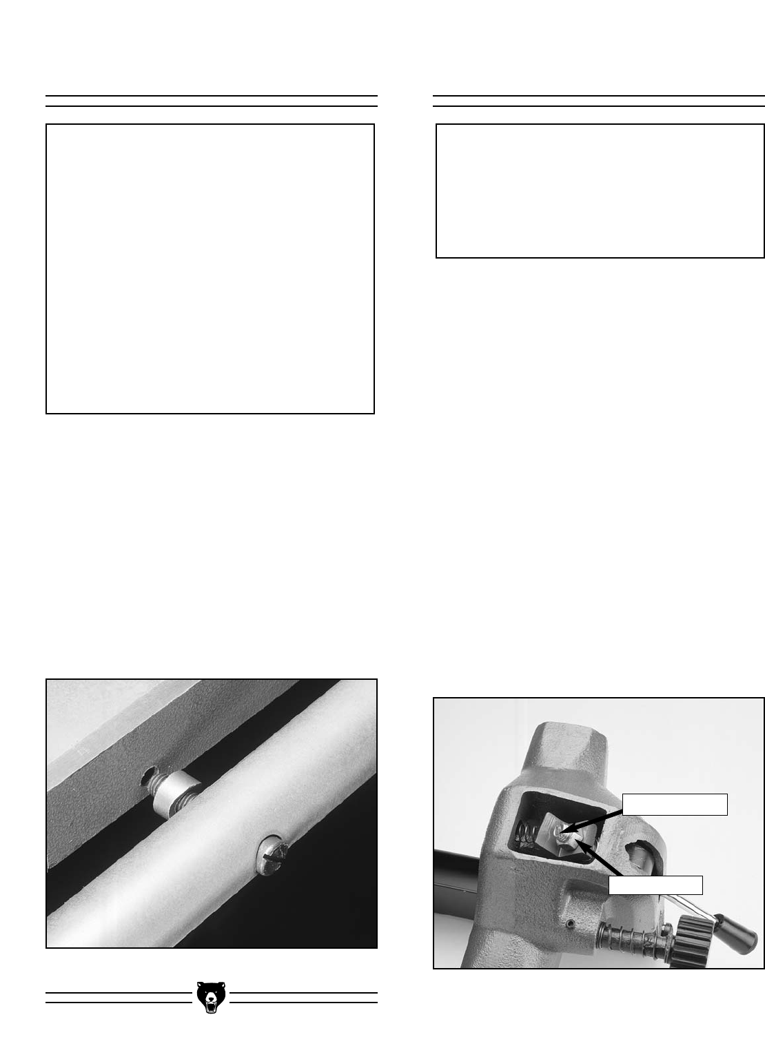
5. Locate the motor mount bracket shown in
Figure 18. Loosen the setscrew that holds
the motor pivot rod in place and remove the
rod.
Figure 15. Attaching the motor plate.
To mount the motor:
1. Turn the motor upside down and attach the
motor plate using M8-1.25 x 25 hex bolts,
8MM flat washers and M8-1.25 hex nuts as
shown in Figure 15. Finger-tighten only.
Motor
Figure 16. Pulley guard bracket.
2. Insert the 1⁄4''-20 x 2'' hex bolt through the
hole in the pulley guard bracket as shown in
Figure 16.
The motor comes
pre-wired.
Motor Mount Plate
Motor Mount Plate
1⁄4''-20 x 2'' Hex Bolt
Pulley Guard Bracket
Pulley Guard Bracket
Motor pictures shown are specific to the
Models SM & Z. The Models ZF, ZFX, PROZ,
& PROZX will look different but will assem-
ble in the same way.
NOTICE
G1022 Series Table Saws -23-
Figure 18. Installing the motor mount bracket.
Figure 19. Attaching motor to linking bars.
6. Line up the hole in the motor bracket with the
hole in the motor mount plate and insert the
motor pivot rod. Make sure the groove in the
rod lines up with the setscrew in the mount
bracket.
7. Tighten the setscrew.
8. Turn the arbor tilting handwheel until the
arbor is set to 0°.
9. Slide the motor assembly onto the linking
bars through the holes in the motor bracket
as shown in Figure 19.
10. Line up the setscrews with the grooves on
the linking bars and tighten them.
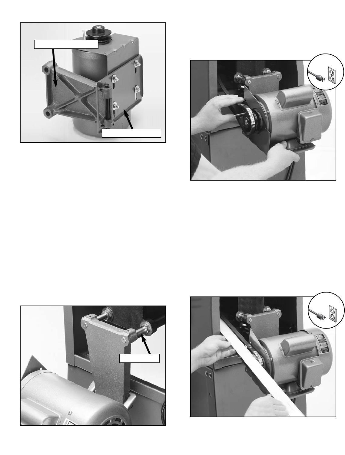
Figure 20. Attaching the V-belt to the motor.
11. Lift the motor up and slip the V-belt over the
grooves in the pulleys. Slowly release the
motor, allowing its weight to add tension to
the V-Belt as shown in Figure 20.
Motor Mount Plate
Linking Bars
Motor Mount Bracket
Figure 21. Checking V-belt alignment.
12. Place a straightedge across the arbor pulley
and the motor pulley. The straightedge
should run across both pulleys evenly as
shown in Figure 21.
13. If the motor needs to be adjusted, loosen the
mounting bolt tightened in Step 4.
14. Adjust the motor on its mount until the pul-
leys are aligned, then tighten all the mount-
ing bolts.
!
!

-24- G1022 Series Table Saws
Figure 22. Attached pulley cover.
15. Using the supplied wing nut and mounting
bolt, secure the pulley cover over the pulley
and V-belt as shown in Figure 22.
Switch
Models SM & Z:
The ON/OFF switch, with attached power cord
and plug, is already mounted to the saw enclo-
sure. Connect the quick disconnect on the cord
between the switch and motor.
Models ZF, ZFX, PROZ, & PROZX:
The ON/OFF switch on the Models ZF, ZFX,
PROZ, & PROZX mounts directly below the front
fence rail.
To install the switch:
1. Disconnect the machine from the power
source!!
2. Position the L-shaped mounting bracket
below the left-hand side of the front fence
rail. The shorter side of the L has two holes
which will align with two holes in the fence
rail.
3. Secure the bracket to the rail using M8-1.25
x 9 hex bolts and M8 flat washers (Model
PROZ: M8-1.25 x 15 countersunk phillips
head screws, M8-1.25 hex nuts, and M8 flat
washers).
4. Secure the switch to the bracket using M4-
0.7 x 14 phillips head screws and M4 flat
washers. The screws thread through the
back of the bracket and into threaded inserts
in the back side of the switch box.
5. Connect the plug on the cord between the
switch and motor.

G1022 Series Table Saws -25-
Figure 23. Checking table to wing alignment.
5. Raise or lower the rear of the wing until the
wing and table are flush. Tighten the bolt.
6. Repeat Steps 2-5 for the other extension
wing.
7. Check the alignment of the table against
both wings. Your straightedge should run flat
across both wings and the table top. If the
straightedge contacts both the wings and the
table evenly, you may skip to the next sec-
tion. If it does not, continue to Step 8.
8. If either wing tilts down, remove it and apply
layers of masking tape along the entire edge
of the wing under the bolt holes.
9. If the wing tilts up, apply layers of masking
tape along the entire edge of the wing above
the bolt holes.
10. Tighten bolts and adjust again as described
in Steps 2-5.
11. Trim off the excess masking tape with a
razor blade.
To install the extension wings:
1. Attach the extension wings to the table using
M10 - 1.5 x 25 hex bolts and M10 flat wash-
ers.
2. Thread the center bolt in first, then the front
and back bolts. DO NOT completely tighten
the bolts at this time.
3. Working front to back, align the front edge of
the extension wing with the edge of the table,
so they are flush, and tighten the front bolt.
4. Raise or lower the rear of the extension wing
until the middle of the wing is flush with the
table top and tighten the middle bolt as
shown in Figure 23.
The Model SM has sheet metal wings; the
Models Z, ZF, and ZFX uses slotted cast
iron wings; and the Models PROZ & PROZX
use solid cast iron wings. Installation is
identical with all styles.
NOTICE
Extension Wings
-26- G1022 Series Table Saws
The fence must engage and square up on the
front rail before the rear clamp engages the back
rail. In essence, the rear clamp should act as a
secondary mechanism for maintaining fence
position. When adjusted correctly, the lever lock
should only begin to apply pressure on the back
rail over the last one-third of its stroke.
To install and adjust the Model SM fence:
1. Thread the plastic knob onto the lock handle.
2. Slide the fence onto the rails.
3. Make sure the front clamp engages the front
rail with the lock handle at one-half of its
throw.
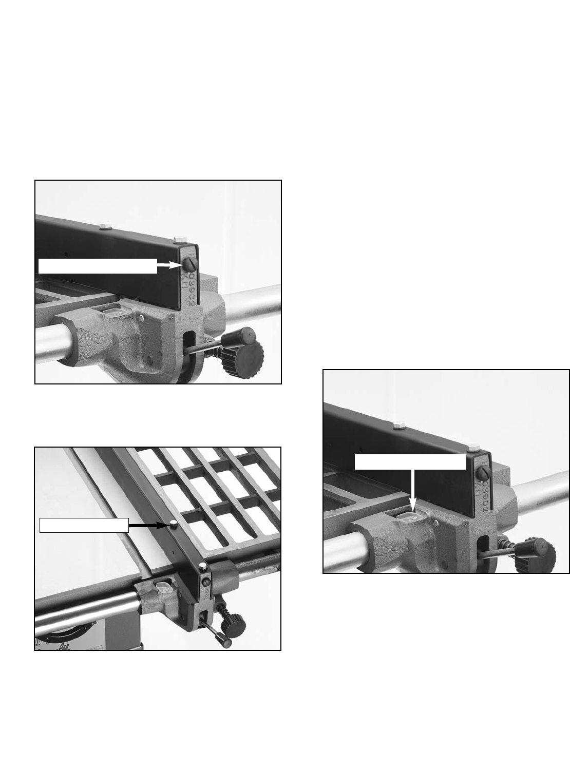
4. If the front clamp requires adjustment,
loosen the check nut shown in Figure 25.
Turn the adjusting bolt clockwise if the front
clamp is too far from the rail, or counter-
clockwise if it is too close.
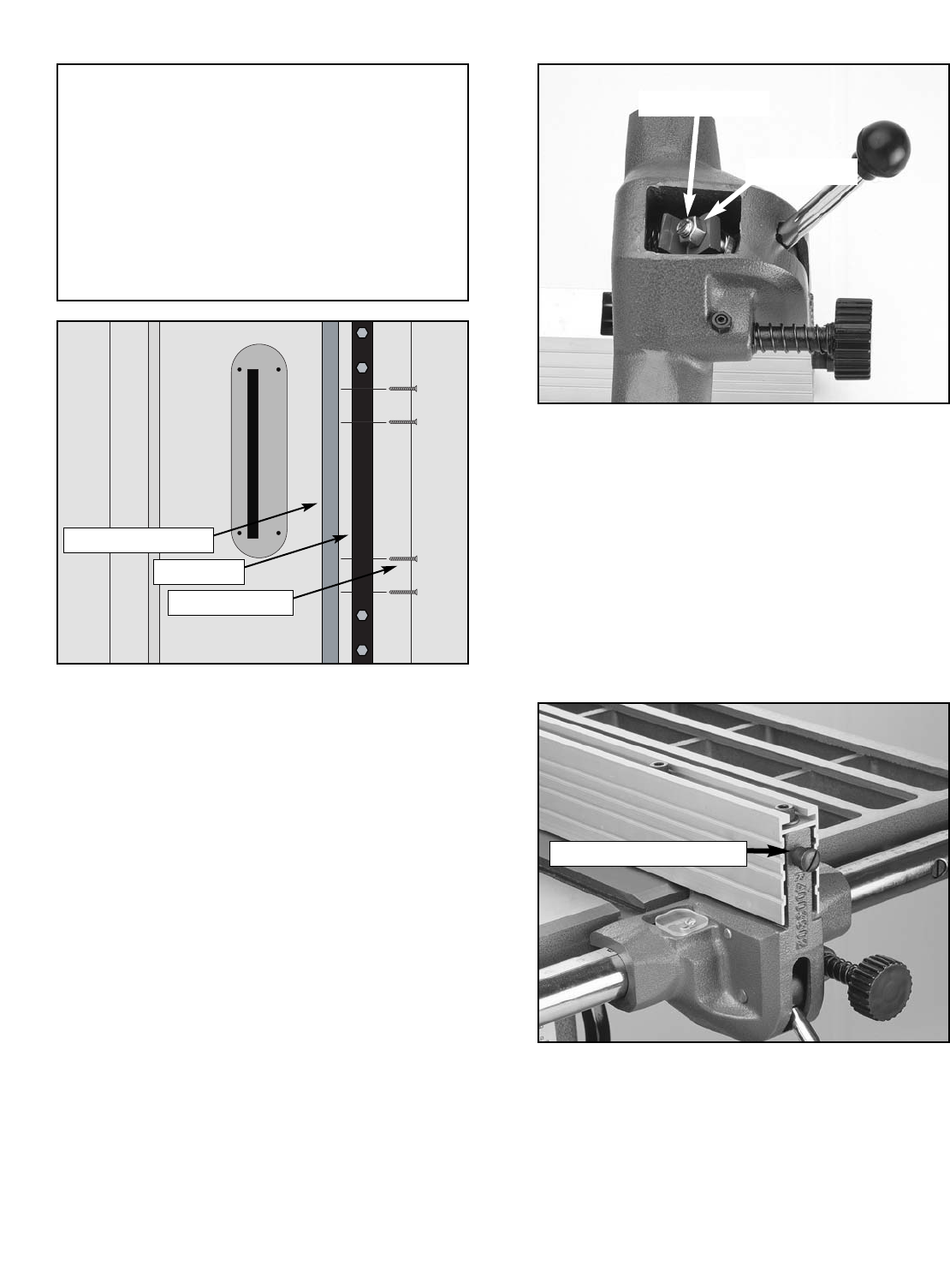
Figure 24. Attaching fence rails.
Fence Rails
To mount the rails (Models SM & Z):
The two center bolts for each rail thread directly
into the table top, and the outer two bolts secure
from the back side of the extension wing with hex
nuts.
Place a spacer on each bolt between the rail and
the table/wing edge as shown in Figure 24.Be
sure that the rail with the built-in measuring rule is
mounted on the front side of the machine, with
the markings facing up. Insert the round, plastic
plugs into the ends of each rail.
Fence
The Models SM & Z are supplied with
round rails, the Models ZF, ZFX, & PROZX
are supplied with flat angular bar sections
and the Model PROZ is supplied with
square tube rails. This accommodates the
standard fence for the Models SM & Z, the
SHOP FOX®Heavy-Duty fence for the
Models ZF, ZFX, & PROZX, and the SHOP
FOX®Classic fence for the Model PROZ.
Please refer to the SHOP FOX®manuals for
complete information regarding the instal-
lation of the front and back fence rails on
the Models ZX, ZXF, PROZ, & PROZX.
NOTICE
The Models ZX, ZXF, PROZ, & PROZX use a
SHOP FOX®brand fence. Please refer to the
manual included with the SHOP FOX®fence
for adjusting instructions.
NOTICE
Figure 25. Adjusting clamp mechanism.
Check Nut
Adjusting Bolt
G1022 Series Table Saws -27-
Figure 26. Rear lock adjustment screw.
5. Slide the fence along the rail until it is
aligned with the edge of the miter slot.
6. Lock the fence down.
7. Loosen the rear lock adjustment, the slotted
screw on the front of the fence shown in
Figure 26, until the rear locking clamp ceas-
es to engage the rear rail with the fence in
the locked position.
Rear Lock Adjustment
6. Loosen the adjustment bolts at the top of the
fence shown in Figure 27.
8. Move the straight portion of the fence until it
is parallel with the miter slot from front to
back. Retighten the bolts.
9. Loosen the locking handle until it is approxi-
mately two-thirds engaged.
10. Tighten the rear adjusting screw until the
rear clamp barely touches the back rail.
11. Loosen the locking handle and slide the
fence along the rail. Return the fence to its
position at the edge of the miter slot and
slowly apply pressure to the lever.
If adjustments are correct, the fence should
square itself before the rear clamp engages.
If the rear clamp engages before the fence is
squared, loosen the screw one-quarter turn
and retest.
12. Once the fence is adjusted, check the mea-
surement pointer shown in Figure 28 and
adjust if necessary.
Figure 27. Adjustment bolts for
fence parallelism.
Adjustment Bolts
Figure 28. Adjust measurement pointer.
Measurement Pointer
-28- G1022 Series Table Saws
Figure 29. Attaching a sacrificial fence.
Tip: Attach a piece of 3⁄4" thick hardwood to
the blade side of the fence as shown in
Figure 29. This will keep thin materials from
wedging between the fence and table and will
also protect the fence from coming in contact
with the blade when dadoing or ripping thin
stock. Remember to flip and adjust the mea-
surement scale on the rail to compensate for
the thickness of the sacrificial fence.
To install and adjust the Model Z fence:
1. First, make sure the front clamp is engaging
the front rail with the lock handle at one-half
of its throw.
2. If the front clamp requires adjustment,
loosen the check nut shown in Figure 30.
Turn the adjusting bolt clockwise if the front
clamp is too far from the rail, counter-clock-
wise if it is too close.
Figure 30. Adjusting clamp mechanism.
Check Nut
Adjusting Bolt
Figure 31. Rear lock adjustment screw.
3. Slide the fence along the rail until it is
aligned with the edge of the miter slot.
4. Lock the fence down.
5. Loosen the rear lock adjustment (the slotted
screw on the front of the fence shown in
Figure 31) until the rear locking clamp
ceases to engage the rear rail with the fence
in the locked position.
Rear Lock Adjustment
Wood Screws
Rip Fence
Sacrificial Fence

G1022 Series Table Saws -29-
7. Make note of its position and lift it up all the
way. Tighten the rear adjustment screw until
the rear clamp is approximately 1⁄16'' from the
rail.
8. Move the lock handle back to its two-thirds
position. The rear clamp should just be
touching the rail. If it is too loose or too tight,
lift the handle and turn the adjusting screw in
small increments until the clamp is in its
proper location.
9. Loosen the locking handle and slide the
fence along the rail. Return the fence to its
position at the edge of the miter slot and
slowly apply pressure to the handle.
10. If adjustments are correct, the fence should
square itself before the rear clamp engages.
If the rear clamp engages before the fence is
squared, loosen the screw one-quarter turn
and retest.
Figure 32. Adjustment bolts for
fence parallelism.
Front Adjustment Screws
Locking Handle
6. Loosen the locking handle (Figure 32) until it
is approximately two-thirds engaged.
Do not turn the adjustment screw unless
the lock handle is in the up position.
Damage to the clamp shoe will result if this
step is not observed.
Figure 33. Adjust measurement pointer.
11. Once the fence is adjusted, check the mea-
surement pointer shown in Figure 33, and
adjust if necessary.
Measurement Pointer
Figure 34. Attaching a sacrificial fence.
Tip: Attach a piece of 3⁄4" thick hardwood to
the blade side of the fence as shown in
Figure 34. This will keep thin materials from
wedging between the fence and table and will
also protect the fence from coming in contact
with the blade when dadoing or ripping thin
stock. Remember to flip and adjust the mea-
surement scale on the rail to compensate for
the thickness of the sacrificial fence.
Wood Screws
Rip Fence
Sacrificial Fence
NOTICE
-30- G1022 Series Table Saws
To install a saw blade:
1. Disconnect the machine from the power
source!!
2. The arbor nut has left-hand threads.
Unthread the arbor nut clockwise and
remove the outside flange from the arbor.
Remove and discard the 3⁄4'' diameter spacer
on the arbor shaft.
4. Slide on the flange and thread the arbor nut
back on.
5. Use the arbor wrench provided with the saw
to tighten the arbor nut. Wedge a block of
wood in the teeth of the blade to keep it from
turning when tightening the nut as shown in
Figure 35.
3. Install the saw blade onto the arbor. Ensure
that the blade teeth point toward you as you
stand at the front of the saw.
Use caution and remain
alert when working with
the saw blade. Failure
to follow this warning
could result in serious
personal injury or
death.
Blade
Figure 35. Changing saw blade.
!
G1022 Series Table Saws -31-
Figure 37. Blade guard components.
5. Rotate the support shaft to align the mount-
ing bolts to the mounting slots on the guard.
6. Tighten the mounting bolts to secure the
blade guard.
7. Using a machinist's or a combination square,
align the face of the splitter perpendicular to
the surface of the saw table as shown in
Figure 38.
8. Rotate the support shaft slightly. This will
normally correct any minor misalignment.
Figure 38. Adjusting blade guard.
Support Shaft
Blade Guard Mounting Bolts
Blade Guard
Support Shaft
Blade Guard
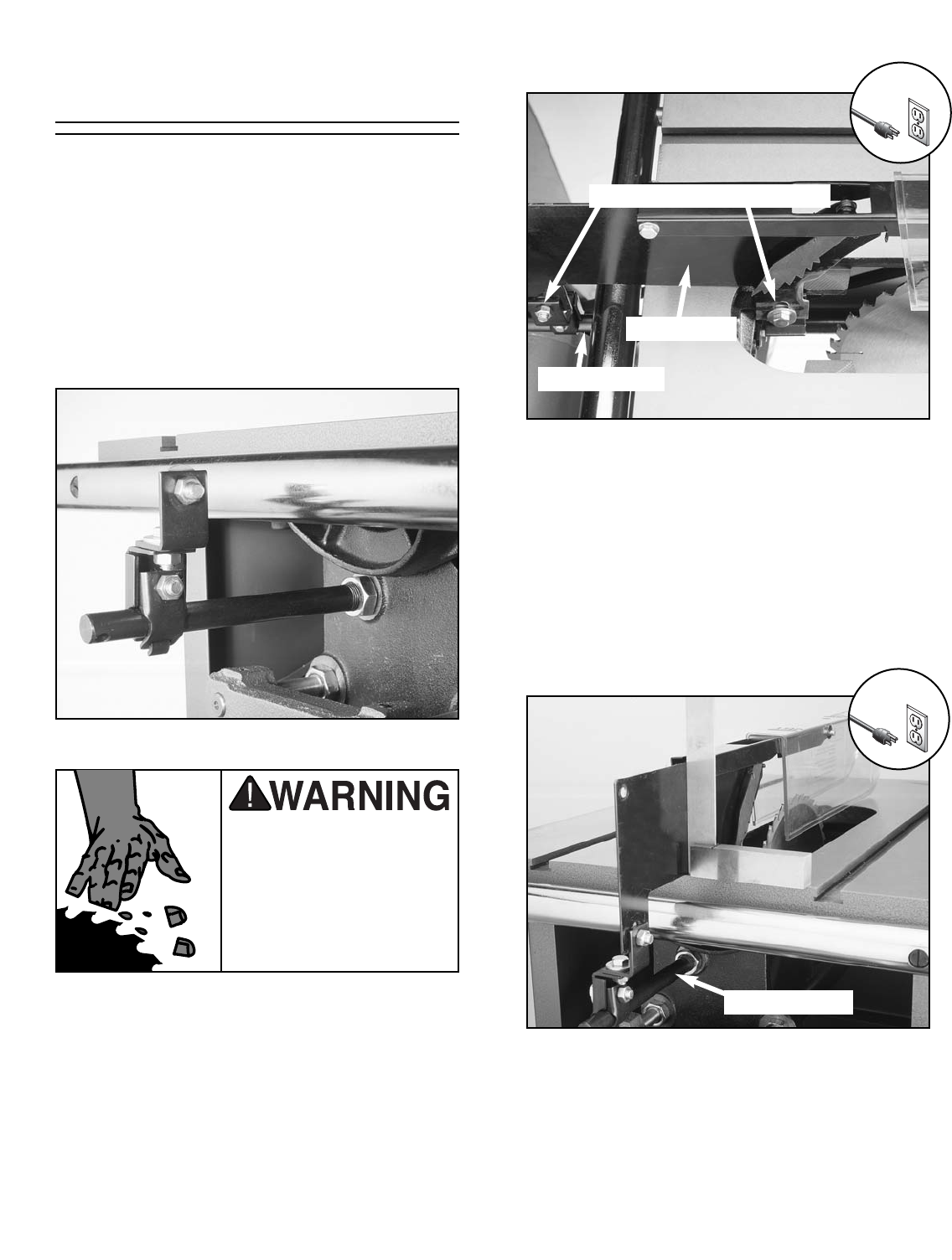
To install the blade guard:
1. Disconnect the machine from the power
source!!
2. Screw the threaded end of the support shaft
into the hole in the back of the rear trunnion.
The check nut on the shaft will be used to
tighten the shaft in place as shown in Figure
36. Leave it loose for now.
Figure 36. Installing blade guard.
3. Loosen the blade-guard mounting bolt locat-
ed just inside the table cut-out and the blade
guard mounting bolt on the end of the sup-
port shaft.
4. Slip the slots at the bottom of the guard over
the two mounting bolts as shown in Figure
37.The washers should be between the bolt
head and the slots.
Use caution and remain
alert when working
around the saw blade.
Failure to follow this
warning could result in
serious personal injury
or death.
!
!
-32- G1022 Series Table Saws
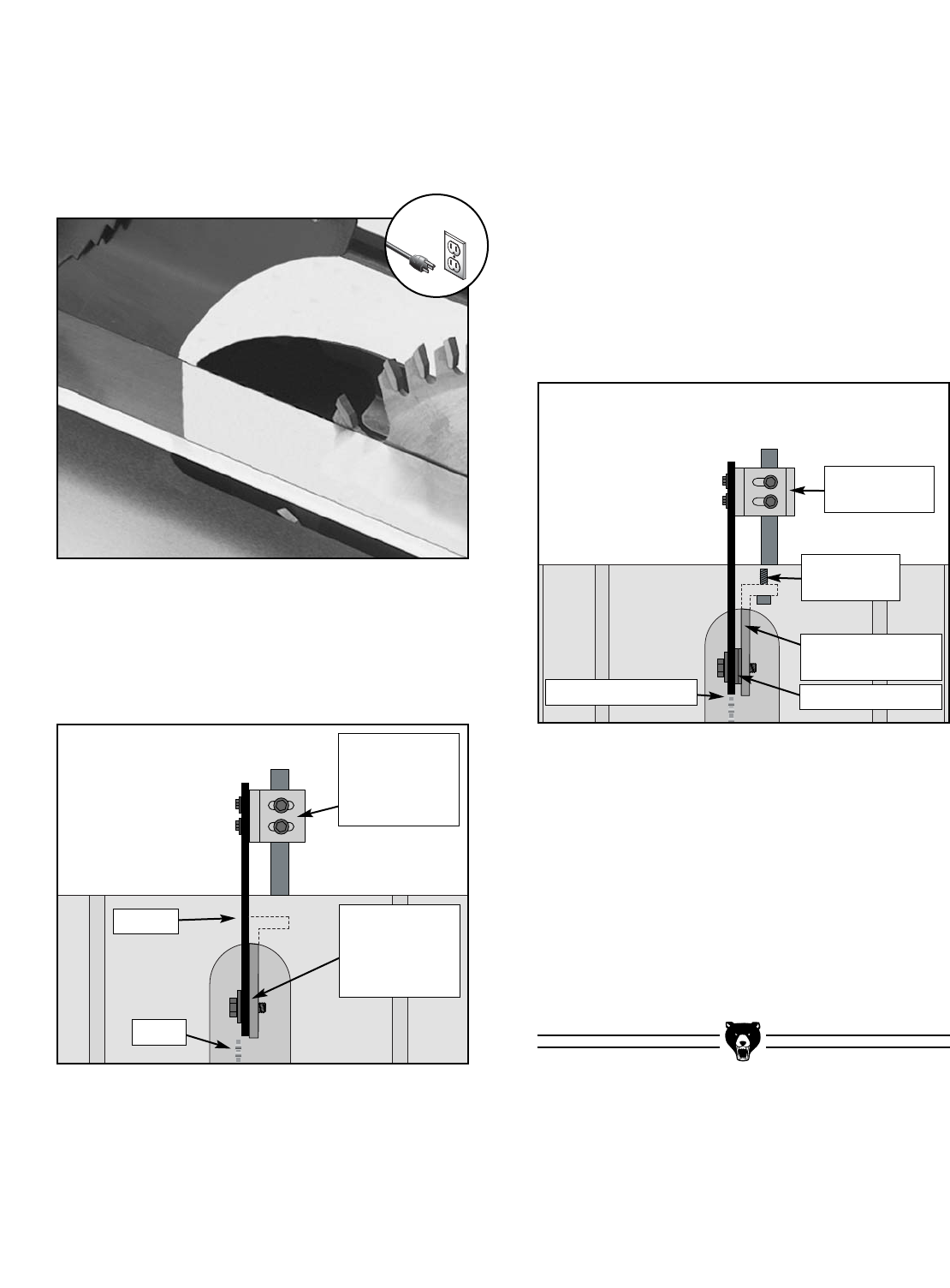
Figure 41. Proper splitter/blade alignment.
13. Recheck guard alignment to the blade and to
the table top. Adjust as necessary and tight-
en down all the bolts before use.
14. Adjust the blade to 45° and raise and lower
it through the full range. Re-adjust blade to
90° and raise and lower it through the full
range. There should be no contact between
the base and the table insert or any other
part of the saw. If there is, repeat Steps 1-
13.
10. If the blade guard/splitter is to the right of the
blade as shown in Figure 40, add washers
between the splitter and front mounting
bracket and adjust the rear splitter support as
shown in Figure 40.
Figure 40. Improper splitter/blade alignment.
Figure 39. Checking alignment of blade guard.
9. Next, set a straightedge against the face of
the saw blade and the blade guard/splitter as
shown in Figure 39.If the blade guard/split-
ter is properly aligned, please skip ahead to
the next section; otherwise, continue with the
next step.
11. Recheck guard alignment to the blade and to
the table top. Adjust as necessary and tight-
en all the bolts before use. If the blade guard
is properly aligned, please skip ahead to the
next section; otherwise, continue with the
next step.
12. If the splitter is positioned to the left of the
blade, alignment cannot be achieved by
washer placement. Adjustment of the front
support bracket is required as shown in
Figure 41. Loosen the adjustment screws
and move the front support bracket to the
right.
Splitter
Added Washers
Front Support
Bracket
Adjustment
Screw
Adjusted
Rear Splitter
Adjust here
to move back
of splitter left
or right.
Add washers
here to move
front of split-
ter to the left.
Blade
Proper Alignment
!
G1022 Series Table Saws -33-
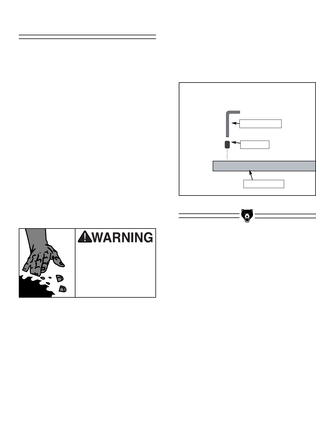
Table Insert
The table insert provides support for the material
being cut. It must be installed flush with the cast
iron table surface.
To install the table insert:
1. Disconnect the machine from the power
source!
2. Using the front handwheel, move the blade
to its lowest position.
3. Set the table insert into the recessed area on
the table surface.
4. Ensure that all four table insert setscrews are
firmly in contact with the table casting.
5. Using an allen wrench, raise or lower each of
the four setscrews until the insert is flush
with the table top as shown in Figure 42.
6. Using the side handwheel, position the blade
90° to the table surface.
7. Wearing leather gloves, rotate the blade while
raising and lowering it through its full range of
motion. Make sure it never contacts any part
of the table insert.
8. Repeat Step 6 with the blade in the 45° posi-
tion.
Figure 42. Adjusting table insert components.
Setscrew
Allen Wrench
Table Insert
Wear leather gloves
when rotating the saw
blade. Failure to follow
this warning could
result in serious per-
sonal injury or death.

-34- G1022 Series Contractor Saws
Miter Gauge
Initial Step Models ZF, ZFX, PROZ, & PROZX:
The miter gauge for the Models ZF, ZFX, PROZ,
& PROZX has two setscrews in the miter bar
which can be set to remove any loose movement
between the miter bar and the T-slot.
Loosen or tighten the two setscrews until the
miter gauge slides freely in the slot, but has no
loose movement.
Next steps for all models:
1. Loosen the lock knob on the miter gauge and
place a square against the face of the miter
body and the miter bar.
2. Adjust the miter body until there is no space
between the square and the miter bar.
3. Tighten the lock knob.
4. With the stop link (Figure 43) in the up posi-
tion, loosen the jam nut and adjust the stop
screw until it is seated against the stop link.
5. Loosen the setscrew on the left front side of
the miter bar, adjust the pointer to 90˚ and
retighten the setscrew.
6. To adjust to 45˚, follow Steps 1-5 while using
an adjustable square.
7. After rotating the miter body from 45˚ to 90˚
and back a few times, double check your
adjustments at both angles to ensure that
you have accurately set your miter gauge.
Figure 43. Miter gauge adjustment points.
Stop Link
Jam Nut
Stop Screw
G1022 Series Table Saws -35-
Before starting the machine:
1. Read this manual and make sure you take all
safety precautions before operating this
machine.
2. Make sure the blade guard and splitter have
been correctly installed and are adjusted
properly as shown on Pages 30-31.
3. Make sure that any tools or foreign objects
have been removed from the machine.
4. Review Section 3: Circuit Requirements
beginning on Page 9 and make sure all
wiring is correct.
5. Keep your finger on the STOP button during
the entire test run of the machine.
Starting the machine:
Turn the machine on and make sure your hand is
on the STOP button in case you need to shut the
machine off immediately. The machine should
run smoothly with little or no vibration.
Start Up Recommended
Adjustments
For your convenience, the adjustments listed
below have been performed at the factory and no
further setup is required to operate your machine.
However, because of the many variables
involved with shipping, we recommend that you
at least check the following adjustments to
ensure the best possible results from your new
machine.
All of these adjustments are covered in step-by-
step detail in Section 8: Service Adjustments.
Recommended adjustment checklist:
•Blade Parallelism (Page 49)
•45˚ Blade Stop (Page 52)
•90˚ Blade Stop (Page 52)
Loose hair and clothing
could get caught in
machinery causing seri-
ous personal injury.
Keep loose clothing
rolled up and long hair
tied up and away from
machinery.
Projectiles thrown from
the machine could cause
serious eye injury. Wear
safety glasses during
assembly.

-36- G1022 Series Table Saws
Blade Selection
Choosing the correct blade for the job is essential
for the safe and efficient use of your table saw.
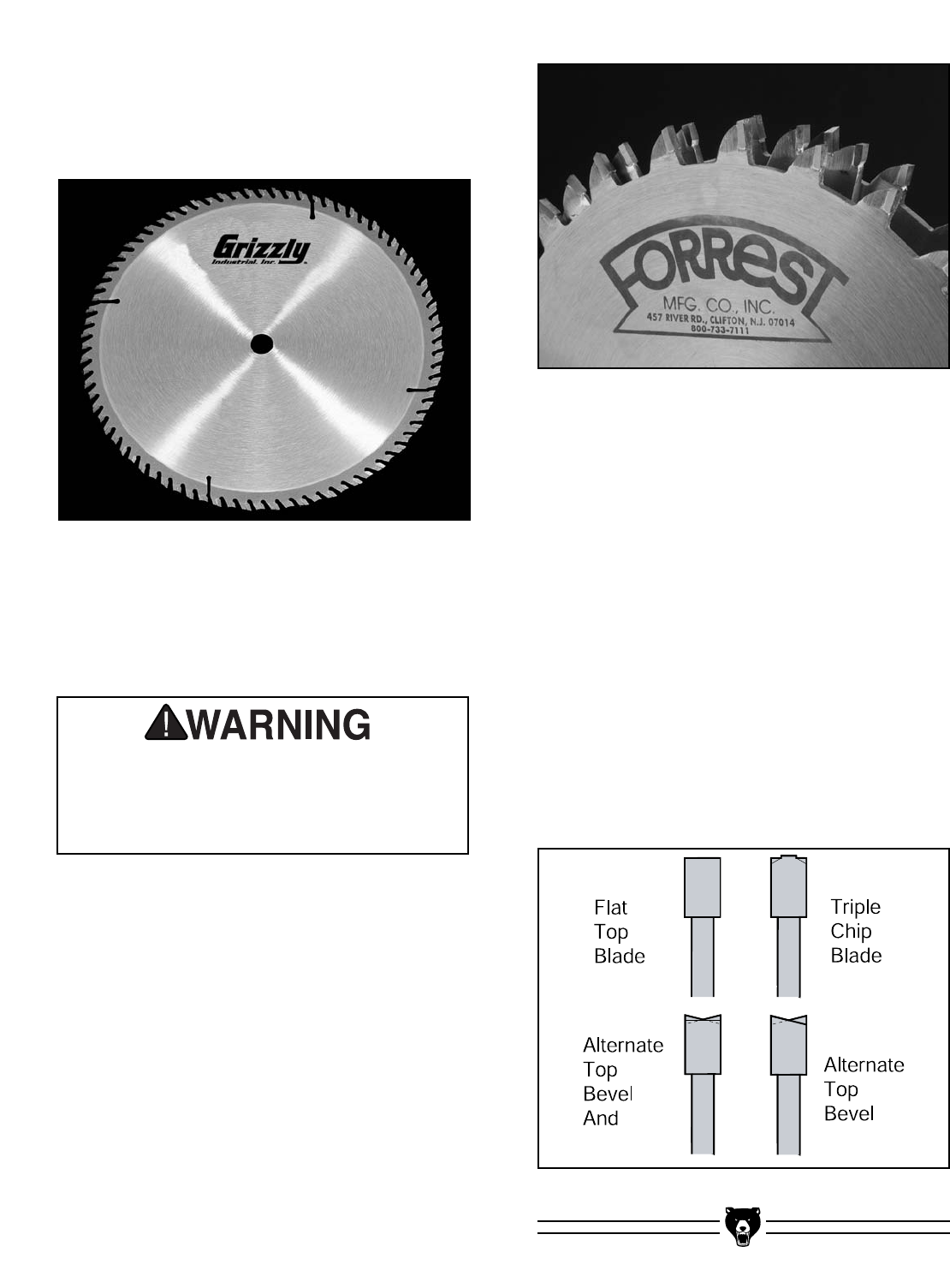
Rip Blade: Used for cutting with the grain. 10" rip
blades have between 20-40 teeth (Figure 44),
flat-top ground tooth profile (Figure 49) and large
gullets to allow for large chip removal.
Figure 44. Ripping blade.
Combination Blade: Used for cutting with and
across the grain. A compromise between a rip
blade and a cross-cut blade, a 10" combination
blade will typically have between 40-50 teeth
(Figure 46), an alternate top bevel and flat or
alternate top bevel (Figure 49) and raker tooth
profile. The teeth are arranged in groups of five.
The gullets are small and shallow within the
groups of five teeth, similar to a cross-cut blade;
then large and deep between the groups, like a
ripping blade.
Figure 46. Combination blade.
Cross-cut Blade: Used for cutting across the
grain. 10" cross-cut blades have between 60-80
teeth (Figure 45), alternate top bevel or steep
alternate top bevel tooth profiles (Figure 49),
small hook angle and a shallow gullet.
Figure 45. Crosscutting blade.
SECTION 6: OPERATIONS
Wear safety glasses. a dust mask, and
hearing protection while the machine is
running. Failure to do this could result in
serious personal injury.
G1022 Series Table Saws -37-
Figure 47. Plywood blade.
Plywood Blade: Used for cutting plywood or
veneers. 10" plywood blades have 40-80 teeth
(Figure 47), a steep alternate top bevel tooth pro-
file (Figure 49) and very shallow gullet.
Thin-kerf: Designed for saws with smaller
motors and for reducing material waste, thin-kerf
blades are thinner than standard blades.
Performance and accuracy can be maintained by
the use of blade stabilizers.
Dado Blades: There are two types of dado
blades: stacked and wobble.
•Stacked Dado Blade—These dedicated dado
cutting blades consist of a set of up to 8 indi-
vidual blades. Multiple cutters are "stacked"
between two outside blades. The width of the
dado is determined by the combination of cut-
ters that are “stacked” together. The dado is cut
in a single pass leaving a smooth and square
channel in the face of the workpiece as shown
on Page 40. Stacked dado blades are the most
expensive option but are worth considering if
your projects require a lot of visible dado cuts.
A typical stacked dado blade is shown in
Figure 48.
•Wobble Dado Blade—Also a dedicated dado
blade, a wobble blade usually consists of a sin-
gle blade that is tilted on the arbor shaft while it
is spinning. The channel is cut in the face of the
workpiece as the blade passes through its pre-
adjusted width of travel. Wobble blades are an
inexpensive option when visibly pleasing chan-
nels are not a concern.
Moulding Heads: A moulding head is a cutter-
head that attaches to the arbor and holds individ-
ual moulding knives. They should only be used by
professional woodworkers with training beyond
the scope of this manual.
This section on blade selection is by no means
comprehensive. Always follow the saw blade
manufacturer's recommendations to ensure safe
and efficient operation of your table saw.
Some blade guards/splitters are thicker
than thin-kerf blades. DO NOT use the thin-
kerf blade if this is the case or serious per-
sonal injury could result.
Figure 48. Optional dado blade.
Figure 49. Various saw tooth cutting profiles.

-38- G1022 Series Table Saws
Crosscutting
To make a 90˚ crosscut using the miter gauge:
1. Adjust the miter gauge to the 90˚ position.
2. Adjust the fence completely away from the
cutting operation.
3. Position the miter gauge in one of the two
miter slots.
4. Adjust the blade height so the highest saw
tooth protrudes approximately 1⁄4" above the
workpiece.
5. Hold the workpiece against the miter gauge
and line up the cut with the blade.
A crosscut is a cut against the grain direction of
the workpiece. Crosscutting man-made wood
products like plywood is performed by cutting par-
allel to the shortest side.
6. Turn on the saw and allow it to come to full
speed.
7. Hold the workpiece firmly against the face of
the miter gauge and ease it into the blade as
shown in Figure 50.
Figure 50. Cross-cut operation.
Keep the blade guard in
the down position at all
times. Failure to do this
could result in serious
personal injury or death.
Turn off the saw and allow the blade to
come to a complete stop before removing
the cut-off piece. Failure to follow this warn-
ing could result in serious personal injury

G1022 Series Table Saws -39-
Ripping
To make a rip cut:
1. Set the fence to the desired width of cut on
the fence rail scale.
2. Adjust the blade height so the highest saw
tooth protrudes approximately 1⁄4" above the
workpiece.
3. Joint one long edge of the workpiece on a
jointer.
4. Set up any safety devices such as feather-
boards or other anti-kickback devices.
5. With the saw unplugged from the power
source, rotate the blade to make sure it
does not come into contact with any of the
safety devices.
6. Plug the saw into the power source, and turn
on the saw and allow it to come to full speed.
7. The jointed edge of the workpiece must be
slide against the fence during the cutting
operation.
A rip cut is a cut with the grain direction of the
workpiece. Ripping man-made wood products
like plywood is performed by cutting parallel to
the longest side. 8. Using a push stick, feed the workpiece
through the saw blade as shown in Figure
51, until the workpiece is completely past the
saw blade. When a small width is to be
ripped and a push stick cannot be safely put
between the blade and rip fence, rip a larger
piece to obtain the desired piece.
Stand to the left of the blade line-of-cut
when ripping a board. Serious personal
injury could occur if kickback results.
Keep the blade guard in
the down position at all
times. Failure to do this
could result in serious
personal injury or death.
Figure 51. Ripping operation.
Turn off the saw and allow the blade to
come to a complete stop before removing
the cut-off piece. Failure to follow this warn-
ing could result in serious personal injury
-40- G1022 Series Table Saws
Dado Cutting
Commonly used in furniture joinery, a dado is a
straight channel cut in the face of the workpiece.
Dadoes can be cut using either a dado blade
(Figure 57) or a standard saw blade.
To use a stacked or wobble dado blade:
1. Disconnect the machine from the power
source!
2. Remove the table insert, splitter guard, and
regular saw blade.
3. Attach and adjust the dado blade system as
recommended in the dado blade manufac-
turer’s instructions.
4. Install the dado table insert.
5. Raise the dado blade up to the desired depth
of cut (depth of dado channel desired).
Never perform a through cut operation with
a dado blade. A dado blade was designed to
make non-through cuts only. Failure to fol-
low this warning could result in serious per-
sonal injury.
Dado operations present very real hazards
requiring proper procedures to avoid seri-
ous injury. The chance of kickback is
always greater when dado blades are used
so extra care must be taken. Any movement
of the stock away from the fence will cause
kickback. Be certain that stock is flat and
straight. Failure to follow these warnings
could result in serious personal injury.
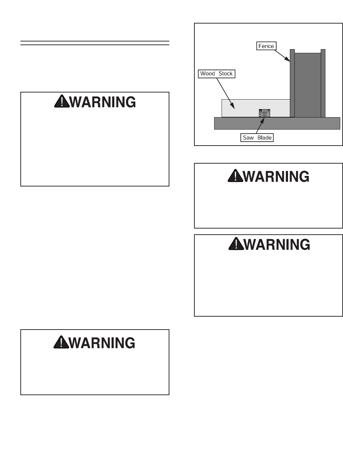
6. If dadoing along the long length of your work-
piece, adjust the distance between the fence
and the inside edge of the blade to suit your
needs as shown in Figure 52.
Always use push sticks, featherboards,
push paddles and other safety accessories
whenever possible to increase safety and
control during operations which require the
blade guard and splitter to be removed from
the saw. Failure to follow this warning could
result in serious personal injury.
Never allow hands or arms to be above or
behind the saw blade. Should kickback
occur, the hands and arms could be pulled
into the saw blade causing serious person-
al injury.
Figure 52. Single-blade dado cut.
7. Reconnect the saw to the power source.
8. With one finger ready to push the OFF but-
ton, turn the saw on. The blade should run
smooth with no vibrations or wobbling.
9. When the blade has reached full speed, per-
form a test cut with a scrap piece of wood.
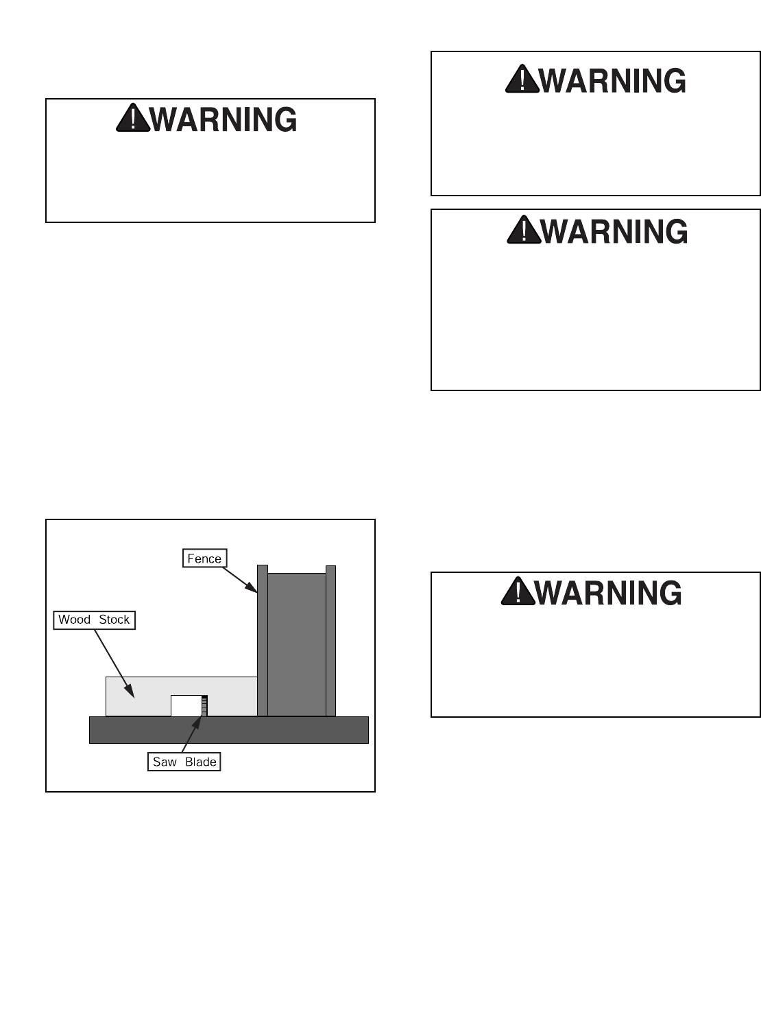
G1022 Series Table Saws -41-
Using a standard saw blade:
1. Clearly mark the width of the dado cut on
your workpiece. Include marks on the edge
of your workpiece so you can clearly identify
your intended cut while the material is laying
flat on the saw table.
2. Raise the blade up to the desired depth of
cut (depth of dado channel desired).
3. If dadoing along the long length of your work-
piece, adjust the fence so the blade is
aligned with the inside of your dado channel
as shown in Figure 53.
Figure 53. Single-blade dado cut.
Always use push sticks, featherboards,
push paddles and other safety accessories
whenever possible to increase safety and
control during operations which require the
blade guard and splitter to be removed from
the saw. Failure to follow this warning could
result in serious personal injury.
Never allow hands or arms to be above or
behind the saw blade. Should kickback
occur, the hands and arms could be pulled
into the saw blade causing serious person-
al injury.
10. If the cut is satisfactory, repeat with your fin-
ish stock.
ALWAYS replace the blade guard after
dadoing is complete. Failure to follow this
warning could result in serious personal
injury.
4. Turn on the saw and allow the blade to reach
full speed.
5. Perform a test cut on a scrap piece of wood.
Determine if the depth of cut is correct.
6. If the cut is satisfactory, repeat with your fin-
ish stock.
Always turn the saw off and wait until the
blade has come to a complete stop before
adjusting the fence. Failure to follow this
warning could result in serious personal
injury.
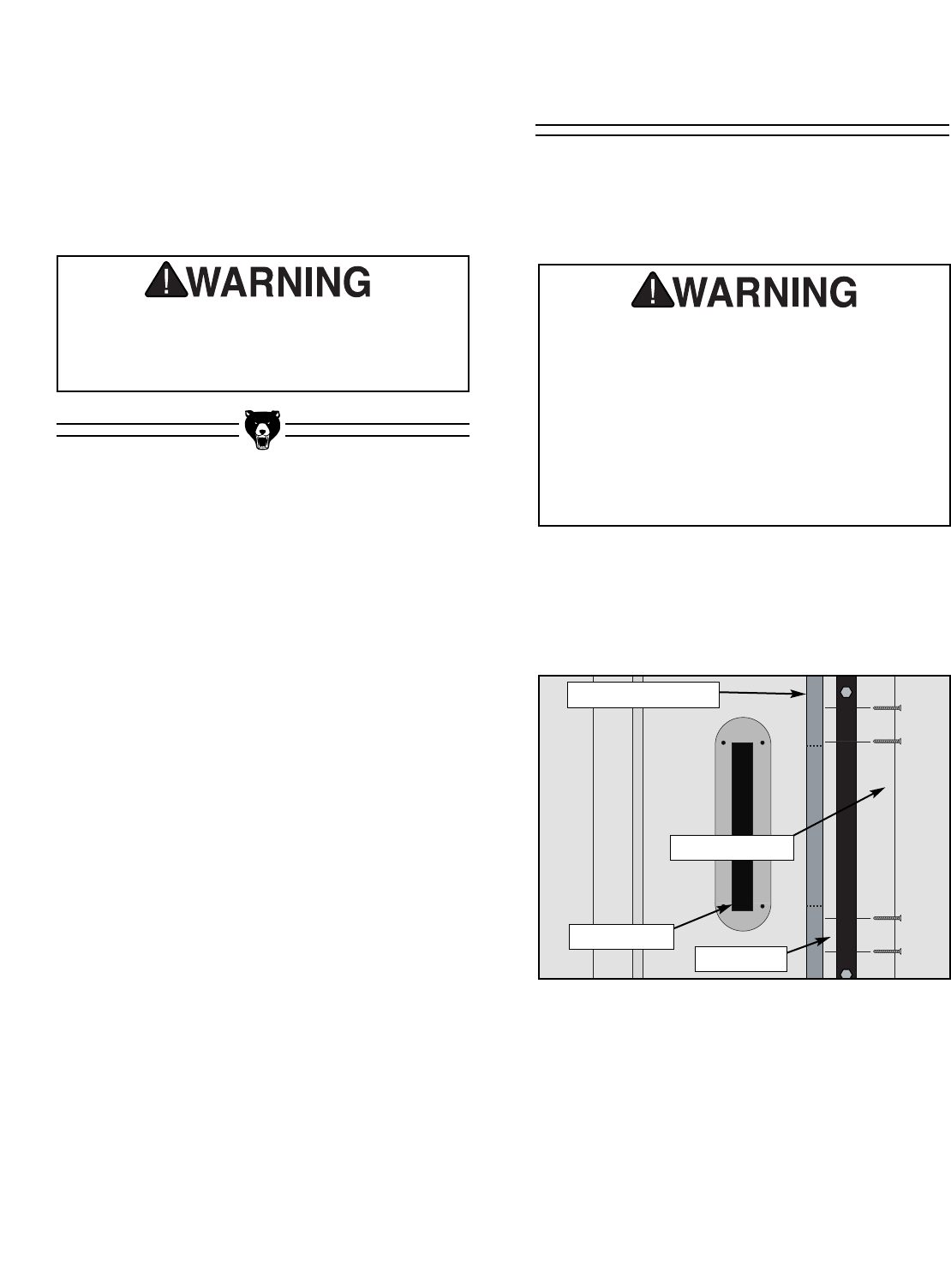
-42- G1022 Series Table Saws
7. Re-adjust the fence so the blade is aligned
with the other edge of the intended dado
channel. Be sure to keep the cuts within your
marks; otherwise, the dado will be too big.
8. Continue making cuts toward the center of
the dado with your subsequent cuts until the
dado is complete.
Rabbet Cutting
Always replace the blade guard after dado-
ing is complete. Failure to follow this warn-
ing could result in serious personal injury.
To attach a sacrificial fence:
Rabbet cutting with a dado blade requires the use
of a sacrificial fence attachment as shown in
Figure 54.
Commonly used in furniture joinery, a rabbet is a
straight groove cut in the edge of the workpiece.
Rabbets can be cut using either a dado blade
(Figure 49) or a standard saw blade.
Rabbet operations present very real haz-
ards requiring proper procedures to avoid
serious injury. The chance of kickback is
always greater when dado blades are used
so extra care must be taken. Any movement
of the stock away from the fence will cause
kickback. Be certain that stock is flat and
straight. Failure to follow these warnings
could result in serious personal injury.
Figure 54. Sacrificial fence.
Dado Insert
Rip Fence
Wood Screws
Sacrificial Fence
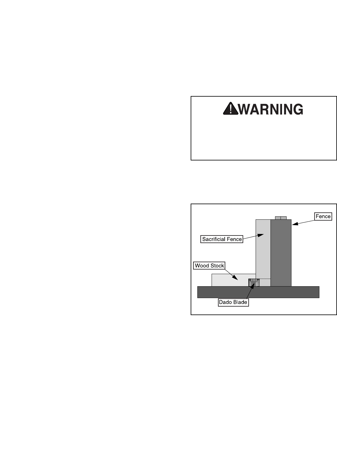
G1022 Series Table Saws -43-
1. Disconnect the machine from the power!
2. Cut a piece of wood that is as long and tall as
the metal fence and 3⁄4" thick. This will be the
sacrificial fence. Make sure the wood is a
uniform thickness and free of knots and
defects.
3. Attach the sacrificial fence to the metal fence
with screws or clamps.
4. Remove the blade guard/splitter assembly,
the table insert, and the regular saw blade
from the arbor.
5. Install and adjust the dado blade system as
recommended in the dado blade instructions.
6. Adjust the saw blade to maximum height
needed for the rabbeting operation.
7. Raise the blade an additional 1⁄4".
8. Slide the metal fence with the attached sac-
rificial fence along side the blade.
9. Using a felt pen, draw the blade profile onto
the sacrificial fence.
10. Remove the sacrificial fence from the metal
fence.
11. Using a bandsaw or jig saw, cut the marked
blade profile from the sacrificial fence.
12. Re-attach the sacrificial fence to the metal
fence with screws or clamps.
13. Slide the fence assembly over the saw blade.
The blade should NOT touch the sacrificial
fence.
Cutting rabbets with the dado blade:
1. Adjust the saw blade to the maximum height
needed for the rabbeting operation.
Never perform a through cut operation with
a dado blade. A dado blade was designed to
make non-through cuts only. Failure to fol-
low this warning could result in serious per-
sonal injury.
2. If rabbeting along the long length of your
workpiece, adjust the distance between the
fence and the workpiece to suit your needs
as shown in Figure 55.
Figure 55. Rabbet cutting.
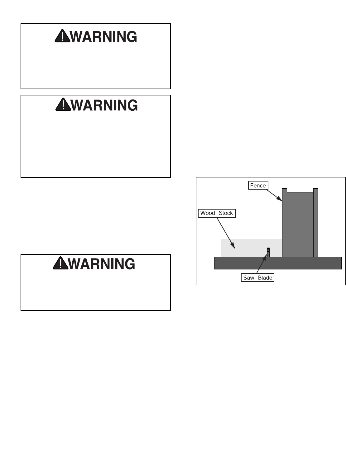
-44- G1022 Series Table Saws
Always use push sticks, featherboards,
push paddles and other safety accessories
whenever possible to increase safety and
control during operations which require the
blade guard and splitter to be removed from
the saw. Failure to follow this warning could
result in serious personal injury.
Never allow hands or arms to be above or
behind the saw blade. Should kickback
occur, the hands and arms can be pulled
into the saw blade. Serious personal injury
could result.
3. Reconnect the saw to the power source and
turn the saw on.
4. When the blade has reached full speed, per-
form a test cut with a scrap piece of wood.
5. If the cut is satisfactory, repeat with your fin-
ish stock.
Always replace the blade guard after rabbet
cutting is complete. Failure to follow this
warning could result in serious personal
injury.
Cutting rabbets with the standard blade:
Cutting rabbets with a standard saw blade DOES
NOT require the use of a sacrificial fence.
1. Clearly mark the width of the rabbet cut on
your workpiece. Include marks on the edge
of your workpiece so you can clearly identify
your intended cut while the material is laying
flat on the saw table.
2. Raise the blade up to the desired depth of
cut (depth of rabbet channel desired).
3. If the rabbet runs the length of the material,
adjust the fence so the blade is aligned with
the inside of your rabbet channel as shown
in Figure 56.
Figure 56. Rabbet cutting.
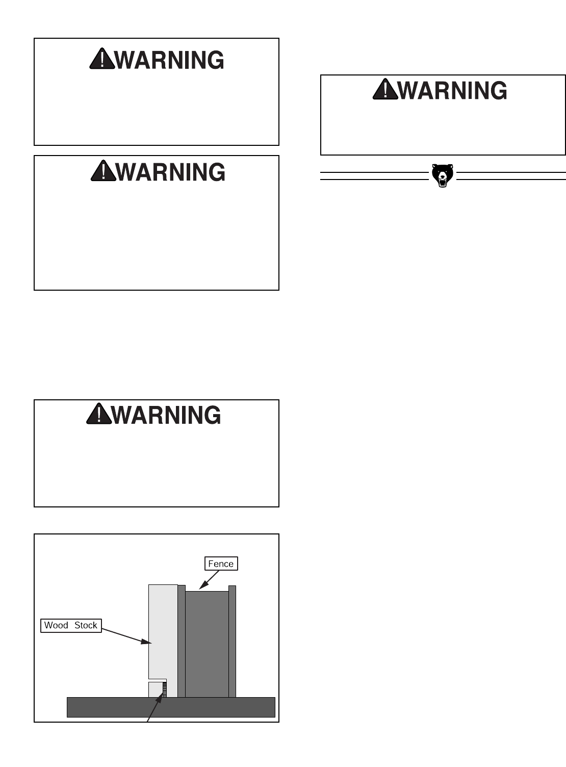
G1022 Series Table Saws -45-
4. Turn the saw on.
5. When the blade has reached full speed, per-
form a test cut with a scrap piece of wood.
6. If the cut is satisfactory, repeat with your fin-
ish stock.
7. Rotate the workpiece as shown in Figure 57.
8. Perform the second cut to complete the rab-
bet cut.
Figure 57. Rabbet cutting.
Always replace the blade guard after dado-
ing is complete. Failure to follow this warn-
ing could result in serious personal injury.
Always use push sticks, featherboards,
push paddles and other safety accessories
whenever possible to increase safety and
control during operations which require the
blade guard and splitter to be removed from
the saw. Failure to follow this warning could
result in serious personal injury.
Never allow hands or arms to be above or
behind the saw blade. Should kickback
occur, the hands and arms can be pulled
into the saw blade. Serious personal injury
could result.
Always turn the saw off and wait until the
blade has come to a complete stop before
adjusting the fence. Failure to follow this
warning could result in serious personal
injury.

-46- G1022 Series Table Saws
SECTION 7: MAINTENANCE
General
Regular periodic maintenance on your Model
G1022 Series Table Saw will ensure its optimum
performance. Make a habit of inspecting your
machine each time you use it.
Check for the following conditions and repair
or replace when necessary:
1. Loose mounting bolts.
2. Worn switch.
3. Worn or damaged cords and plugs.
4. Damaged V-belt.
5. Any other condition that could hamper the
safe operation of this machine.
6. Inspect blades for damage.
7. Guard alignment and operation.
Disconnect power to
the machine when per-
forming any mainte-
nance on the table saw.
Failure to do this could
result in serious per-
sonal injury.
!
Loose hair and clothing
could get caught in
machinery causing seri-
ous personal injury.
Keep loose clothing
rolled up and long hair
tied up and away from
machinery.
Projectiles thrown from
the machine could cause
serious eye injury. Wear
safety glasses during
assembly.

G1022 Series Table Saws -47-
V-Belt
The sealed ball bearings in the motor and
throughout the Model G1022 require no mainte-
nance during their lifetime. When they do wear
out, replacements can be obtained through the
Grizzly Parts Department.
Lubricate the areas indicated below every 12
months:
BLADE ANGLING TRUNNION—The front and
back trunnions each have a semi-circle groove
that needs to be lubricated with an automotive
wheel bearing grease.
BLADE HEIGHT TRUNNION—The blade height
trunnion pivots on a steel rod. This should be
lubricated with 6 or 7 drops of light machine oil.
WORM GEARS (Figure 58)—These should be
lubricated with an automotive wheel bearing
grease.
Lubrication Table
The table is made from cast iron. If preventative
measures are not taken, the table surface will rust.
Regularly wipe sawdust from the table to prevent
rust causing moisture from becoming trapped
against the table. Regular applications of products
like SLIPIT®will prevent rust as the saw is used on
a daily basis. For long term storage, use products
such as Boeshield T-9®. Both of these products
are available in the Grizzly catalog.
Inspect the V-belt regularly for tension and wear.
Check the pulleys to ensure they are correctly
aligned. Refer to Section 5: Set Up beginning on
Page 23 for instructions on adjusting the V-belt.
Figure 58. Worn gear lubrication points.
Lubrication Points

-48- G1022 Series Table Saws
Maintenance Performed
Approximate Hours Of Use
Maintenance Log
Date
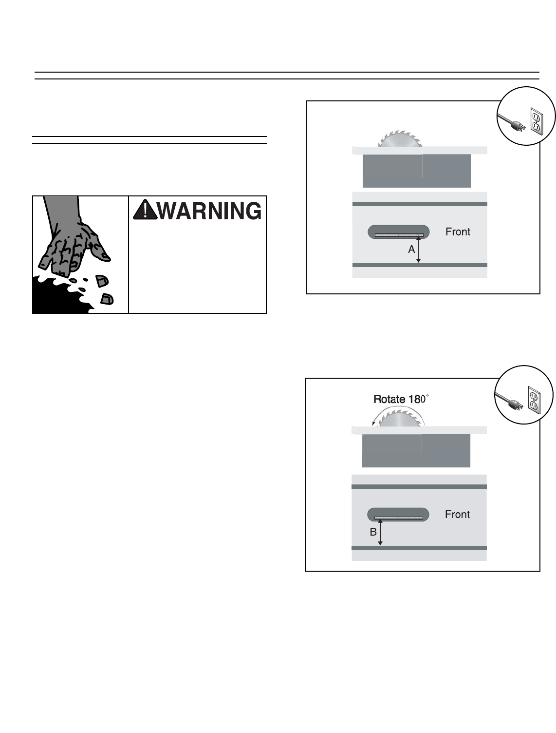
G1022 Series Table Saws -49-
Blade Parallelism
To check and adjust blade parallelism:
1. Disconnect the machine from the power
source!!
2. Tilt the blade to 90˚. Using an adjustable
square, measure the distance (A) between
the miter slot and the front of the blade as
shown in Figure 59.
The Model G1022 Series Table Saws will perform
best when the miter slot is parallel to the blade.
Figure 59. 90° blade parallelism measurement.
Figure 60. 90° blade parallelism measurement.
3. Rotate the blade 180° and measure the dis-
tance (B) between the miter slot and the
back of the blade as shown in Figure 60.
Use caution and remain
alert when working
around the saw blade.
Failure to follow this
warning could result in
serious personal injury
or death.
SECTION 8: SERVICE ADJUSTMENTS
!
!
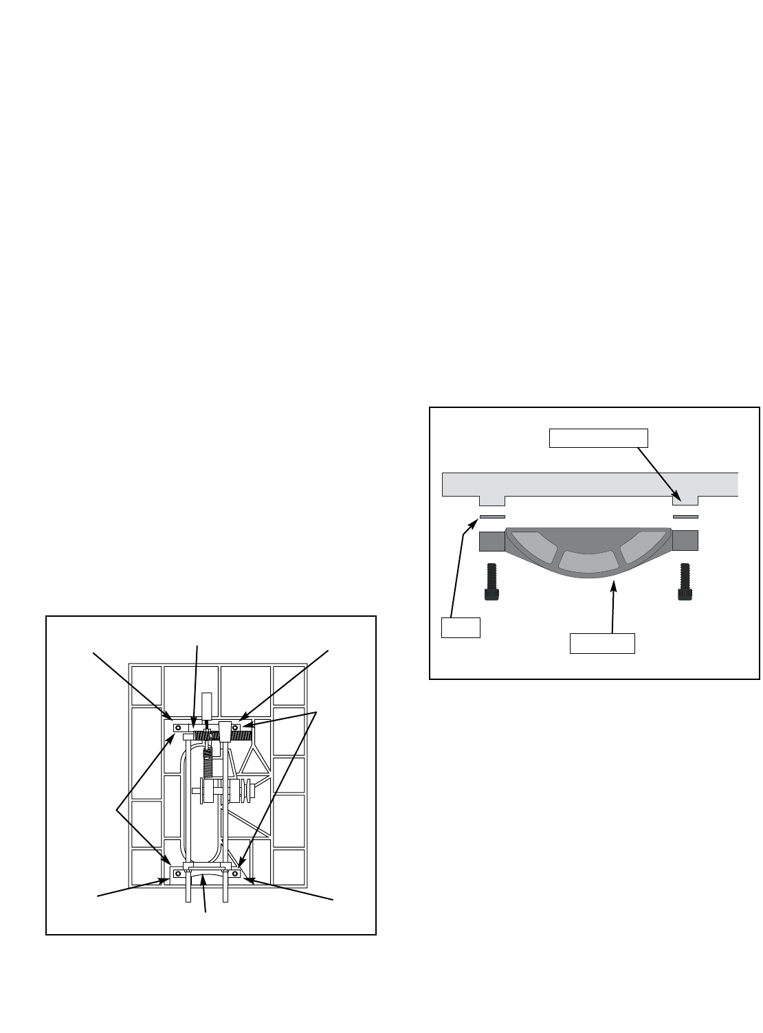
-50- G1022 Series Table Saws
Figure 61. Underside view of
table/trunnion assembly.
4. Make note of the difference between the two
measurements on a piece of paper.
5. Tilt the blade to 45° and repeat Steps 2-4.
6. If the difference was less than 0.004" when
the blade was positioned at 90˚ and 45˚, skip
to the next section. Otherwise, continue on.
7. If the difference was greater than 0.004"
when the blade was positioned at 90˚ or 45˚,
the trunnion assembly below the table needs
to be adjusted.
8. Remove the saw assembly from the stand.
9. Remove the motor, the fence, the extension
wings, and the saw blade.
10. Place the saw assembly upside down on 4x4
blocks to allow the saw blade to rotate freely.
11. Remove the handwheels and the sheet
metal body.
12. To maintain the trunnion assembly as one
unit, place a bar clamp across the entire
trunnion assembly as shown in Figure 61.
If the blade was not parallel in the 90˚ position,
the correction can be made by loosening the trun-
nion bolts and shifting the internal components
accordingly.
To shift the trunnion:
1. Loosen the trunnion bolts.
2. Move the trunnion assembly according to the
difference measured when the blade was in
the 90˚ position.
3. Tighten the trunnion bolts.
If the blade was not parallel in the 45˚ position,
the correction can be made by shimming
between the trunnion and the bottom of the table
surface as shown in Figure 62.
Clamp Here
Clamp Here
Trunnion
Bolts
Trunnion
Bolts
#1 Shim
#3 Shim
#4 Shim
#2 Shim
Figure 62. Shim placement.
Shim
Trunnion
Table Bottom
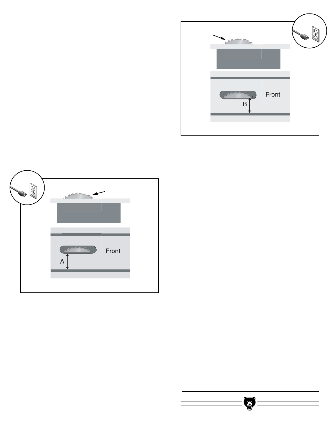
G1022 Series Table Saws -51-
3. Tighten down one trunnion bolt a small
amount and then move on to each of the
others, tightening each down the same
amount.
4. Continue to rotate through the bolts, tight-
ening them a little each time until they are
all secure.
5. Re-assemble the saw assembly onto the
stand.
6. Recheck the blade to miter slot distance at
90° and 45°. If the distance of A and B are
equal to or less than 0.004" at both 90° and
45°, continue to the next section. If the dis-
tances are still off by more than 0.004",
repeat the previous procedures.
7. Once you feel you have the miter slot
adjusted parallel to the blade, recheck all
measurements and be sure the table
mounting bolts are secure.
8. Repeat Step 10 on Page 31.
To shim the trunnion:
1. Loosen the trunnion bolts.
2. Using Figures 63 & 64, shim the trunnion
assembly according to the difference mea-
sured when the blade was in the 45˚ posi-
tion.
If the distance of A is shorter than B, shim(s)
will need to be placed under corners #1 and
#2.
If the distance of B is shorter than A, shim(s)
will need to be placed under corners #3 and
#4. Figure 64. 45° blade parallelism measurement.
#1 Shim
#3 Shim
#2 Shim
Figure 63. 45° blade parallelism measurement.
#1 Shim
45˚ Bevel
45˚ Bevel
#3 Shim
#4 Shim
#4 Shim
#2 Shim
If the trunnion assembly is loosened in the
future, make note of the shim locations
and re-assemble accordingly.
NOTICE
!
!
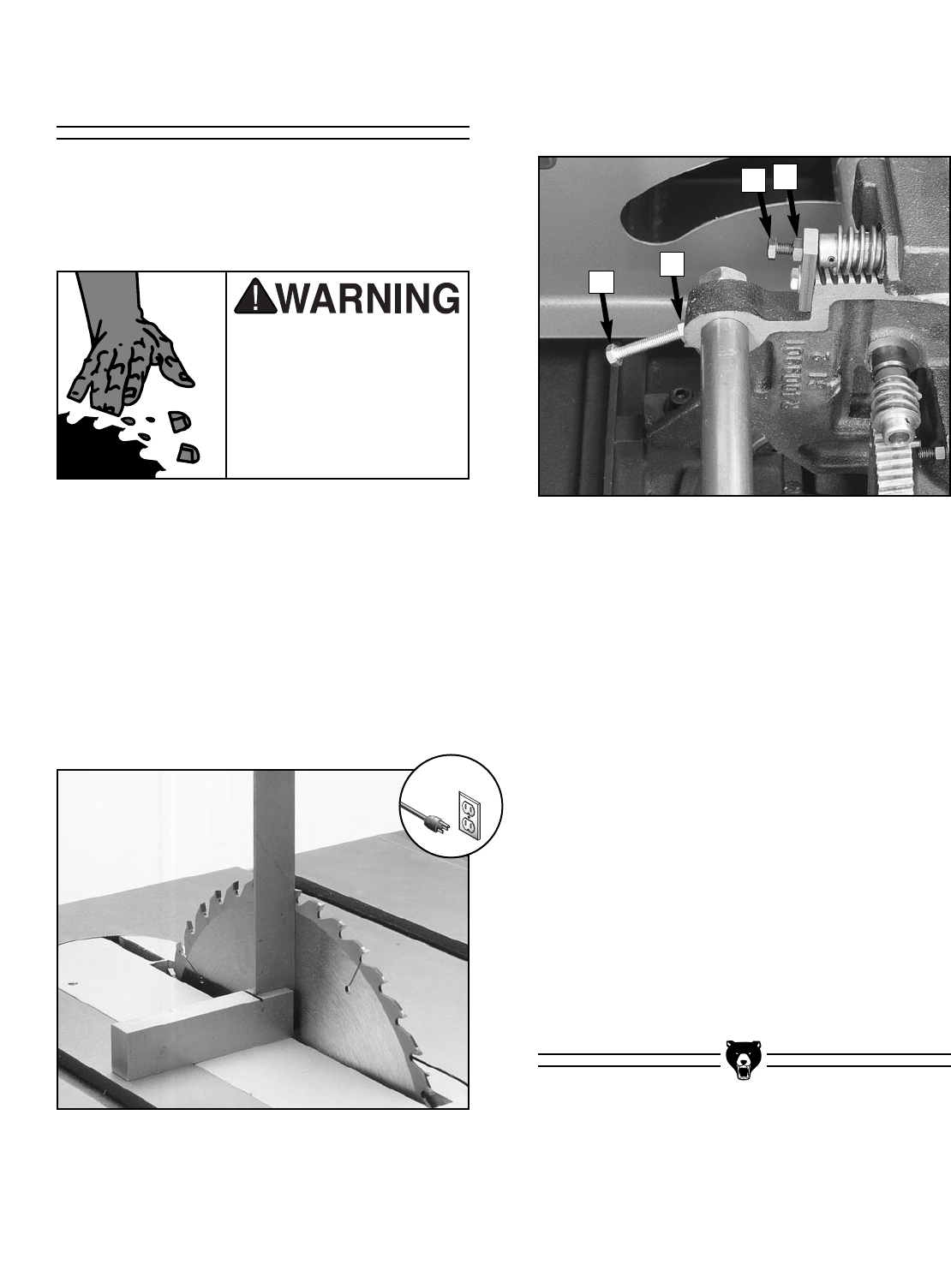
-52- G1022 Series Table Saws
45˚ & 90˚ Stops
The Model G1022 Series Table Saws are
equipped with positive stops at 45° and 90°.
When properly adjusted, they provide precise
and dependable guides for bevel adjustment.
To set the 45˚ & 90˚ stops:
1. Disconnect the machine from the power
source!!
2. Raise the saw blade to its maximum height
by turning the front handwheel clockwise.
3. Adjust the blade to the 90˚ position.
Figure 65. Checking blade angle to table.
5. With the square in place, inspect for gaps
along the blade and square.
6. If a gap exists at either the top or the bottom
of the square, loosen lock nut (A) and adjust-
ment bolt (B) shown in Figure 66.
Figure 66. 90° and 45° stop bolt adjustments.
C
D
BA
Use caution and remain
alert when working
around the saw blade.
Failure to follow this
warning could result in
serious personal injury
or death.
7. Turn the handwheel until the blade and
square are flush from top to bottom.
8. Snug the adjustment screw and tighten the
lock nut.
9. Recheck the blade with the square to ensure
the screw has not been over-tightened.
10. Using the side handwheel, adjust the blade
bevel until you hit the 45° positive stop.
Check the bevel with an adjustable square
set to 45˚.
11. If variations exist, loosen the lock nut (C) and
adjust the stop bolt (D) (Figure 66) until your
blade and square match.
12. Tighten the lock nut and recheck the bevel
by adjusting the blade back to 90°, then back
to 45°.
!
G1022 Series Table Saws -53-
SECTION 9: CLOSURE
The following pages contain general machine
data, parts diagrams/lists, a troubleshooting guide
and Warranty/Return information.
If you need parts or help in assembling your
machine, or if you need operational information,
call the Grizzly Service Department. Trained ser-
vice technicians will be glad to help you.
If you have any comments regarding this manual,
please write to Grizzly at the address below:
Grizzly Industrial, Inc.
C/O Technical Documentation
P.O. Box 2069
Bellingham, WA 98227-2069
Important safety measures that are essential to
the operation of this machine have been
explained in Section 1: Safety. While most safety
measures are generally universal, Grizzly
reminds you that each workshop is different and
safety rules should be considered as they apply to
your specific situation.
We recommend you keep a copy of our current
catalog for complete information regarding
Grizzly's warranty and return policy. If you need
additional technical information relating to this
machine, or if you need general assistance or
replacement parts, please contact the Service
Department at the location listed below.
Grizzly Industrial, Inc.
1203 Lycoming Circle
Muncy, PA 17756
Phone: (570) 546-9663
Fax: (800) 438-5901
E-Mail: techsupport@grizzly.com
Web Site: http://www.grizzly.com.
Additional information sources are necessary to
realize the full potential of this machine. Trade
journals, woodworking magazines, and your local
library are good places to start.
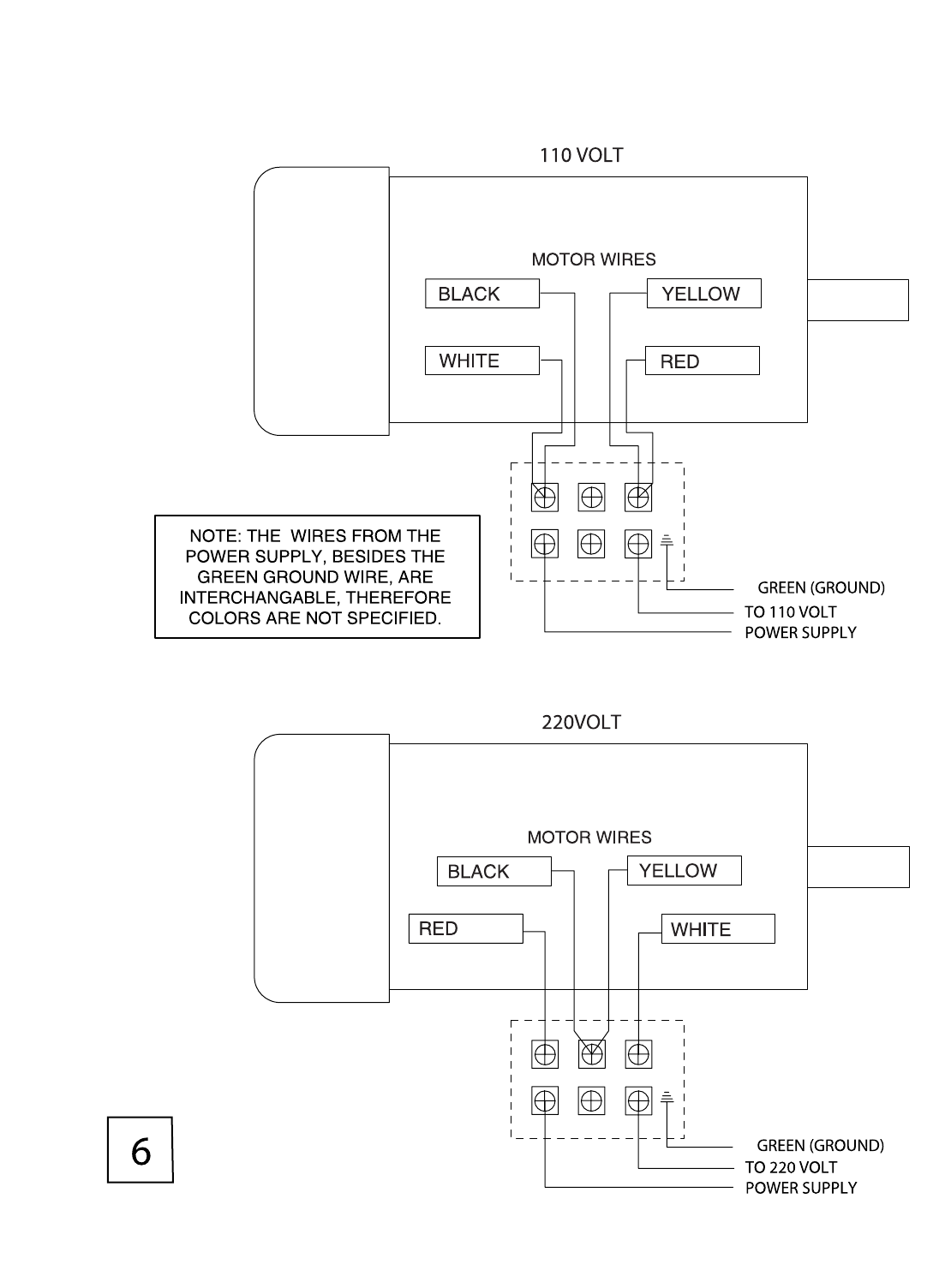
-54- G1022 Series Table Saws
SM AND Z WIRING DIAGRAM
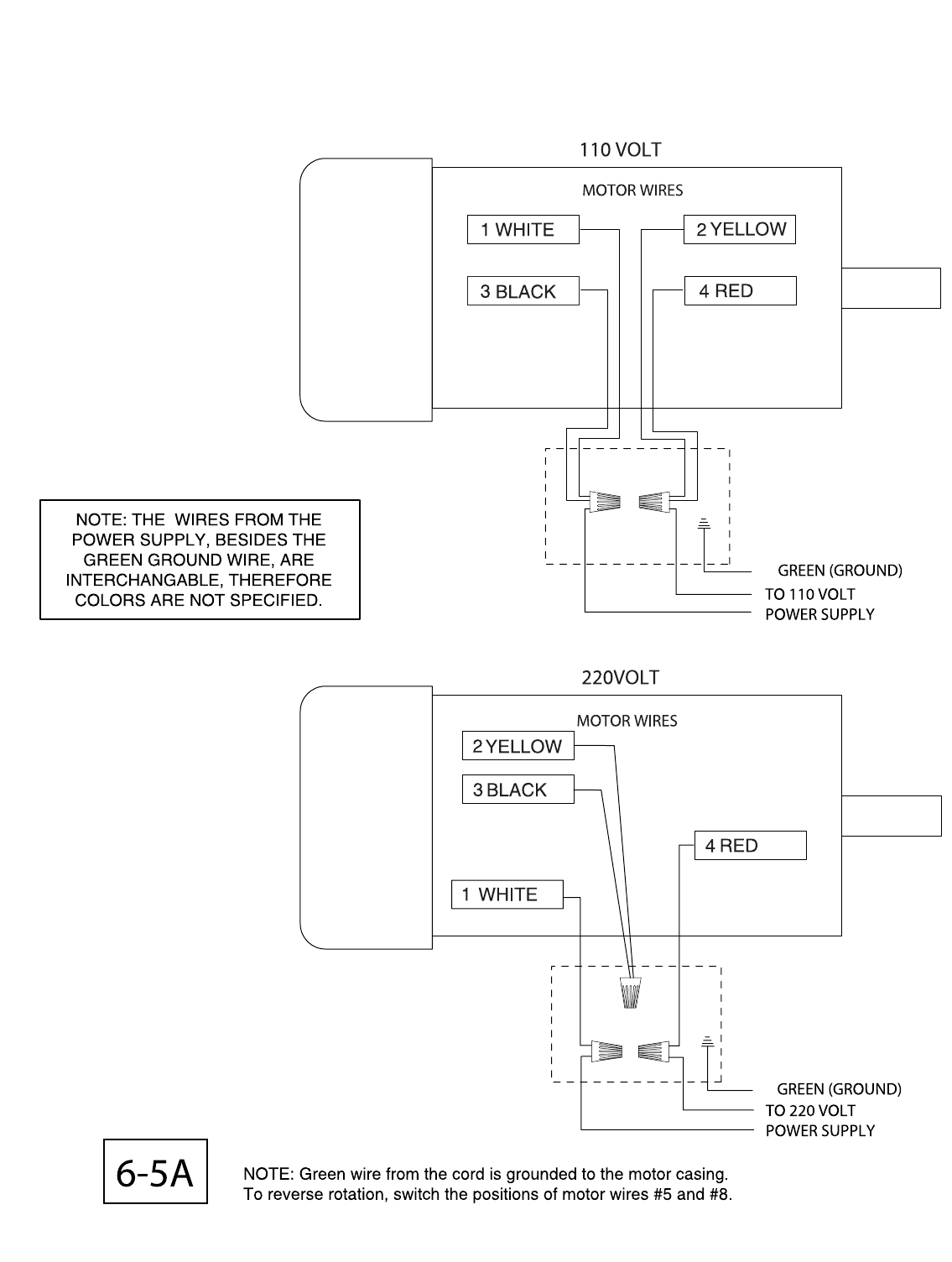
G1022 Series Table Saws -55-
ZF, ZFX, PROZ & PROZX WIRING DIAGRAM

-56- G1022 Series Table Saws
Design Type ......................................................................................................Floor Model
Overall Dimensions:
Table Height ............................................................................................................37"
Table Size ........................................................................................271⁄8" D x 201⁄8" W
Size With Extension Wings ..............................................................271⁄8" D x 405⁄8" W
With Wings and Fence Rails ..................................................................48" W x 44" D
Miter Gauge T-Slot ............................................................................................3⁄8" x 3⁄4"
Weight (Net) ......................................................................................................240 lbs.
Weight (Shipping)..............................................................................................250 lbs.
Box # 1 Size..........................................................................371⁄2" L x 23" W x 181⁄2" H
Box # 2 Size ................................................................................46" L x 3" W x 11⁄2" H
Footprint ........................................................................................................21" x 25"
Construction:
Table ................................................................................................Ground Cast Iron
Stand ..................................................................................................Pre-formed Steel
Miter Gauge ........................................................................................Aluminum ⁄ Steel
Trunnions ........................................................................................................Cast Iron
Bearings............................................................Shielded and Lubricated Ball Bearings
Fence .............................. Single Lever, Front & Rear Locking w/ Micro Adjust Knob
Rails ..........................................................................44" x 13⁄8" Chrome Plated Tubing
Guard ........................................................................................Steel and Clear Plastic
Wings ............................................................................................Formed Sheet Steel
Cutting Capacity:
Maximum Blade Diameter ........................................................................................10"
Maximum Depth of Cut at 90° ................................................................................31⁄8"
Blade Tilt ....................................................................................................0°-45° Right
Maximum Depth of Cut at 45° ................................................................................21⁄8"
Maximum Rip to Right of Blade (Standard)..............................................................24"
Maximum Rip to Right of Blade (Optional Extension Rails) ....................................48"
Maximum Rip to Left of Blade ..................................................................................11"
Distance from Front of Table to Center of Blade ....................................................17"
Distance from Front of Table to Front of Blade........................................................12"
Maximum Width of Dado Cut ..................................................................................13⁄16"
Motor:
Type ............................................................................TEFC Capacitor Start Induction
Horsepower ...................................................................................................... 11⁄2HP
Phase / Cycle ..............................................................................Single Phase ⁄ 60 HZ
Voltage..........................................................................................................110 ⁄ 220V
Prewired ................................................................................................................110V
Amps ..................................................................................................................16 ⁄ 8A
Hertz and RPM..................................................................................60Hz ⁄ 3450 RPM
Power Transfer ..............................................................................................Belt Drive
Switch ..........................................................................................ON/OFF Push Button
Arbor:
Dimensions......................................................................................................5⁄8" x 11⁄4"
Speed ..........................................................................................................4,700 RPM
Features:
........................................Includes Table Inserts for Standard Blade and Dado Blade
Specifications, while deemed accurate, are not guaranteed.
Customer Service #: (570) 546-9663 • To Order Call: (800) 523-4777 • Fax #: (800) 438-5901
MACHINE DATA
SHEET
GRIZZLY MODEL G1022SM 10'' TABLE SAW
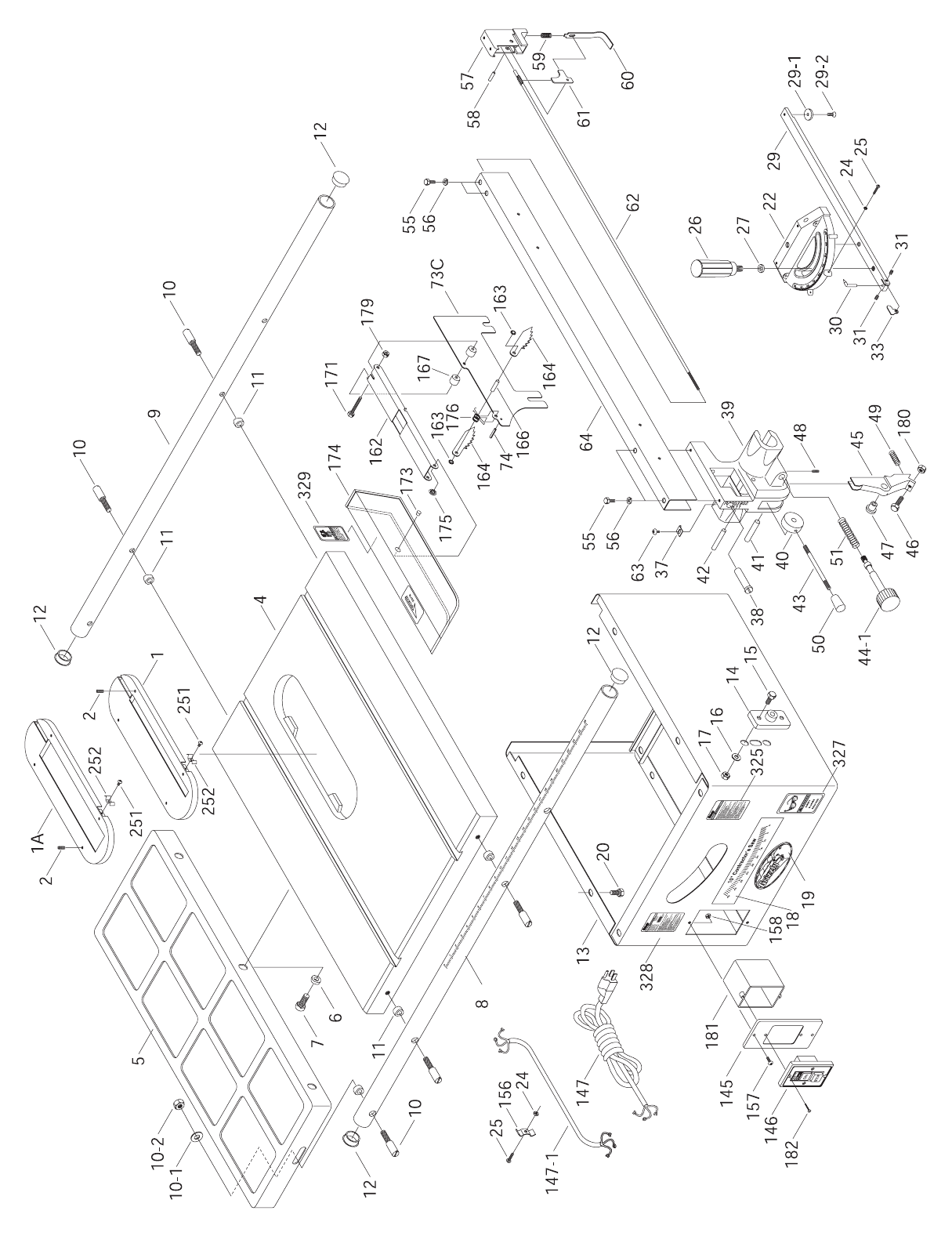
G1022SM
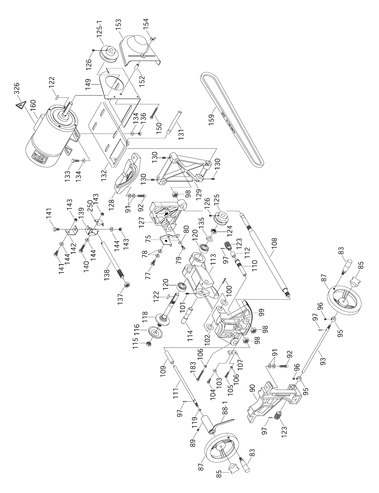
G1022SM
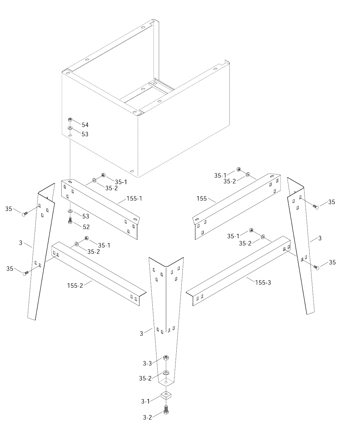
G1022SM

-60- G1022 Series Table Saws
REF PART # DESCRIPTION REF PART # DESCRIPTION
1P1022001 TABLE INSERT
1A P1022001-A DADO INSERT
2PSS04M SETSCREW M6-1.0 x 12
3P1022Z003A STAND LEG
3-1 P1022003-1 FOOT
3-2 PB32M HEX BOLT M10-1.5 x 25
3-3 PN02M HEX NUT M10-1.5
4P1022004 TABLE
5P1022SM005 SHEET METAL WING
6PW04M FLAT WASHER 10MM
7PB01M HEX BOLT M10-1.5 x 30
8P1022008 FRONT GUIDE RAIL
9P1022009 REAR GUIDE RAIL
10 P1022010 SPECIAL RAIL BOLT
10-1 PW04M FLAT WASHER 10MM
10-2 PN02M HEX NUT M10-1.5
11 P1022011 RAIL SPACER
12 P1022012 GUIDE RAIL PLUG
13 P1022013 CABINET
14 P1022014 GEAR BRACKET
15 PB03M HEX BOLT M8-1.25 x 16
16 PW01M FLAT WASHER 8MM
17 PN03M HEX NUT M8-1.25
18 P1022018 TILTING SCALE
19 P1022SM019 LOGO PLATE
20 PB03M HEX BOLT M8-1.25 x 16
21 PW01M FLAT WASHER 8MM
22 P1022022 MITER BODY
24 PN04M HEX NUT M4-0.7
25 PS01M PHLP HD SCR M4-0.7 x 18
26 P1022026 HAND KNOB
27 P1022SM027 FIBER WASHER
29 P1022029 MITER BAR
29-1 P1022029-1 T-SLOT WASHER
29-2 PFH04M FLAT HD SCR M6-1.0 x 8
30 P1022030 ANGLE POINTER
31 PSS02M SETSCREW M6-1.0 x 6
33 P1022033 STOP LINK
35 PCB01M CARR BOLT M8-1.25x20
35-1 PN03M HEX NUT M8-1.25
35-2 PW01M FLAT WASHER 8MM
37 P1022037 WIDTH POINTER
38 P1022038 FENCE ADJUSTER
39 P1022Z039 FRONT CLAMP
40 P1022040 ECCENTRIC
41 P1022041 SHAFT FOR ECCENTRIC
42 P1022042 SHAFT FOR CLAMP
43 P1022043 LOCK LEVER
44-1 P1022044-1 PINION W/ KNOB
45 P1022045 CLAMP SHOE
46 P1022046 ADJUSTING BOLT
47 P1022047 SHAFT BUSHING
48 PSS02M SET SCREW M6-1.0 x 6
49 P1022049 SPRING
50 P1022050 HAND KNOB
51 P1022051 SPRING
52 PB03M HEX BOLT M8-1.25 x 16
53 PW01M FLAT WASHER 8MM
54 PN03M HEX NUT M8-1.25
55 PB06M HEX BOLT M8-1.25 x 12
56 PW01M FLAT WASHER 8MM
57 P1022057 BLOCK
58 P1022058 PIN
59 P1022059 SPRING
60 P1022060 CLAMP HOOK
61 P1022061 LEVER
62 P1022062 LOCK LINK
63 PS05M PHLP HD SCR M5-0.8 x 8
64 P1022064 FENCE
73C P1022073C SPLITTER
74 PRP20M ROLL PIN 4 x 22
75 P1022075 BRACKET
77 PB03M HEX BOLT M8-1.25 x 16
78 PW01M FLAT WASHER 8MM
79 PB02M HEX BOLT M6-1.0 x 12
80 PW03M FLAT WASHER 6MM
83 P1022083 HANDLE
85 P1022085 KNOB
87 P1022087 HANDWHEEL
88-1 P1022088-1 POINTER ASSEMBLY
89 PSS03M SETSCREW M6-1.0 x 8
90 P1022090 FRONT BRACKET
91 PW01M FLAT WASHER 8MM
92 PSB13M CAP SCREW M8-1.25x30
93 P1022093 ANGLE WORM SHAFT
95 P1022095 COLLAR
96 PSS02M SETSCREW M6-1.0 x 6
G1022SM PARTS LIST

G1022 Series Table Saws -61-
REF PART # DESCRIPTION REF PART # DESCRIPTION
97 PRP02M ROLL PIN 3 x 16
98 PN05M HEX NUT M16-1.5
99 P1022090 FRONT TRUNNION
100 PRP06M ROLL PIN 5 X 24
101 PSS04M SET SCR M6 - 1.0 x 12
102 P1022102 WAVY WASHER
103 PW03M FLAT WASHER 6MM
104 PB08M HEX BOLT M6-1.0 x 20
105 PB10M HEX BOLT M6-1.0 x 25
106 PN01M HEX NUT M6-1.0
107 P1022107 SET PLATE
108 P1022108 LINKING BAR
109 P1022109 SPACER
110 P1022110 ECCENTRIC SLEEVE
111 P1022111 WORM SHAFT
112 P1022112 SPACER
113 P1022113 ARBOR BRACKET
114 P1022114 ARBOR BRACKET PIN
115 P1022115 ARBOR NUT
116 P1022116 FLANGE
118 P1022118 BLADE ARBOR
120 P6203 BEARING 6203-2RS
122 PK01M KEY 5 x 5 x 22MM
123 P1022123 WORM
124 P1022124 HEX NUT M17
125 P1022125 SPINDLE PULLEY
125-1 P1022125-1 MOTOR PULLEY
126 PSS03M SETSCREW M6-1.0 x 12
127 P1022127 REAR TRUNNION
128 P1022128 REAR BRACKET
129 P1022129 MOTOR BRACKET
130 PSS04M SETSCREW M6-1.0 x 12
131 P1022131 MOTOR PLATE ROD
132 P1022132 MOTOR PLATE
133 PB07M HEX BOLT M8-1.25 x 25
134 PW01M FLAT WASHER 8MM
135 PLW06 LOCK WASHER 5⁄8"
136 PN03M HEX NUT M8-1.25
137 PN05M HEX NUT M16-1.5
138 P1022138 SHAFT
139 P1022139 BRACKET
140 PB26M HEX BOLT M8-1.25 x 30
141 PB03M HEX BOLT M8-1.25 x 16
142 P1022142 CONNECTING PLATE
143 PN03M HEX NUT M8-1.25
144 PW01M FLAT WASHER 8MM
145 P1022145A SWITCH BRACKET
146 P1022146 SWITCH
147 PWRCRD110S POWER CORD
147-1 PWRCRD110L MOTOR CORD
148 P1022148 SPANNER WRENCH
149 P1022149 PULLEY GUARD BRACKET
150 PB10 HEX BOLT 1⁄4"-20 x 2"
152 P1022152 SLEEVE
153 P1022153 PULLEY COVER
154 PWN02 WING NUT 1⁄4"-20
155 P1022Z155 UPPER BRACKET - LONG
155-1 P1022Z155-1 UPPER BRACKET - SHORT
155-2 P1022Z155-2 LOWER BRACKET - SHORT
155-3 P1022Z155-3 LOWER BRACKET - LONG
156 P1022156 WIRE CLAMP
157 PS08M PHLP HD SCR M5-0.8 x 12
158 PN06M HEX NUT M5-0.8
159 PVA43 V-BELT A-43
160 G2535 MOTOR 11⁄2HP
161 P1022161 STRAIN RELIEF (Not Shown)
162 P1022162 SUPPORTING ARM
163 P1022163 RETAINER
164 P1022164 PAWL
166 P1022Z166 PIN
167 P1022167 SPACER
171 PB47M HEX BOLT M6-1.0 x 40
173 P1022Z173 PIVOT PIN
174 P1022Z174 GUARD
175 P1022Z175 RETAINER
176 P1022068 SPRING
179 PLN03M LOCK NUT M6-1.0
180 PN02M HEX NUT M10-1.5
181 P1022181 SWITCH GUARD
182 PS02M PHLP HD SCR M4-0.7 X 12
183 PB39M HEX BOLT M6-1.0 x 50
250 P1022Z250 CLAMP
251 PS05M PHLP HD SCR M5-0.8 X 8
252 P1022Z252 SPRING
325 P1022SM325 WARNING LABEL
326 P1022SM326 ELECTRICITY LABEL
327 P1022SM327 SAFETY GLASSES LABEL
328 P1022SM328 MACHINE ID LABEL
329 P1022SM329 BLADE GUARD LABEL
G1022SM PARTS LIST

-62- G1022 Series Table Saws
Design Type ......................................................................................................Floor Model
Overall Dimensions:
Table Height ............................................................................................................37"
Table Size ........................................................................................271⁄8" D x 201⁄8" W
Table Size With Extension Wings ....................................................271⁄8" D x 405⁄8" W
Table With Wings and Fence Rails ........................................................48" W x 44" D
Miter Gauge T-Slot ............................................................................................3⁄8" x 3⁄4"
Weight (Net) ......................................................................................................240 lbs.
Weight (Shipping)..............................................................................................250 lbs.
Box # 1 Size ............................................................................36" L x 181⁄2" W x 25" H
Box # 2 Size ..................................................................................46" L x 3" W x 2" H
Box # 3 Size ................................................................................12" L x 12" W x 5" H
Footprint ........................................................................................................21" x 25"
Construction:
Table ................................................................................................Ground Cast Iron
Stand ..................................................................................................Pre-formed Steel
Miter Gauge ........................................................................................Aluminum ⁄ Steel
Trunnions ........................................................................................................Cast Iron
Bearings............................................................Shielded and Lubricated Ball Bearings
Fence ..............................Single Lever; Front & Rear Locking w/ Micro Adjust Knob;
..............................................................Heavy Extruded Aluminum with Tee Slot Top
Rails ..........................................................................44" x 13⁄8" Chrome Plated Tubing
Guard ........................................................................................Steel and Clear Plastic
Wings..............................................................Ground Cast Iron, Open Ribbed Design
Cutting Capacity:
Maximum Blade Diameter ........................................................................................10"
Maximum Depth of Cut at 90° ................................................................................31⁄8"
Blade Tilt ....................................................................................................0°-45° Right
Maximum Depth of Cut at 45° ................................................................................21⁄8"
Maximum Rip to Right of Blade (Standard)..............................................................24"
Maximum Rip to Right of Blade (Optional Extension Rails) ....................................48"
Maximum Rip to Left of Blade ..................................................................................11"
Distance from Front of Table to Center of Blade ....................................................17"
Distance from Front of Table to Front of Blade........................................................12"
Maximum Width of Dado Cut ..................................................................................13⁄16"
Motor:
Type ............................................................................TEFC Capacitor Start Induction
Horsepower ...................................................................................................... 11⁄2HP
Phase / Cycle ..............................................................................Single Phase ⁄ 60 HZ
Voltage..........................................................................................................110 ⁄ 220V
Prewired ................................................................................................................110V
Amps ..................................................................................................................16 ⁄ 8A
Hertz and RPM..................................................................................60Hz ⁄ 3450 RPM
Power Transfer ..............................................................................................Belt Drive
Switch ..........................................................................................ON/OFF Push Button
Arbor:
Dimension........................................................................................................5⁄8" x 11⁄4"
Speed ..........................................................................................................4,700 RPM
Features:
........................................Includes Table Inserts for Standard Blade and Dado Blade
Specifications, while deemed accurate, are not guaranteed.
Customer Service #: (570) 546-9663 • To Order Call: (800) 523-4777 • Fax #: (800) 438-5901
GRIZZLY MODEL G1022Z TABLE SAW
MACHINE DATA
SHEET

G1022Z
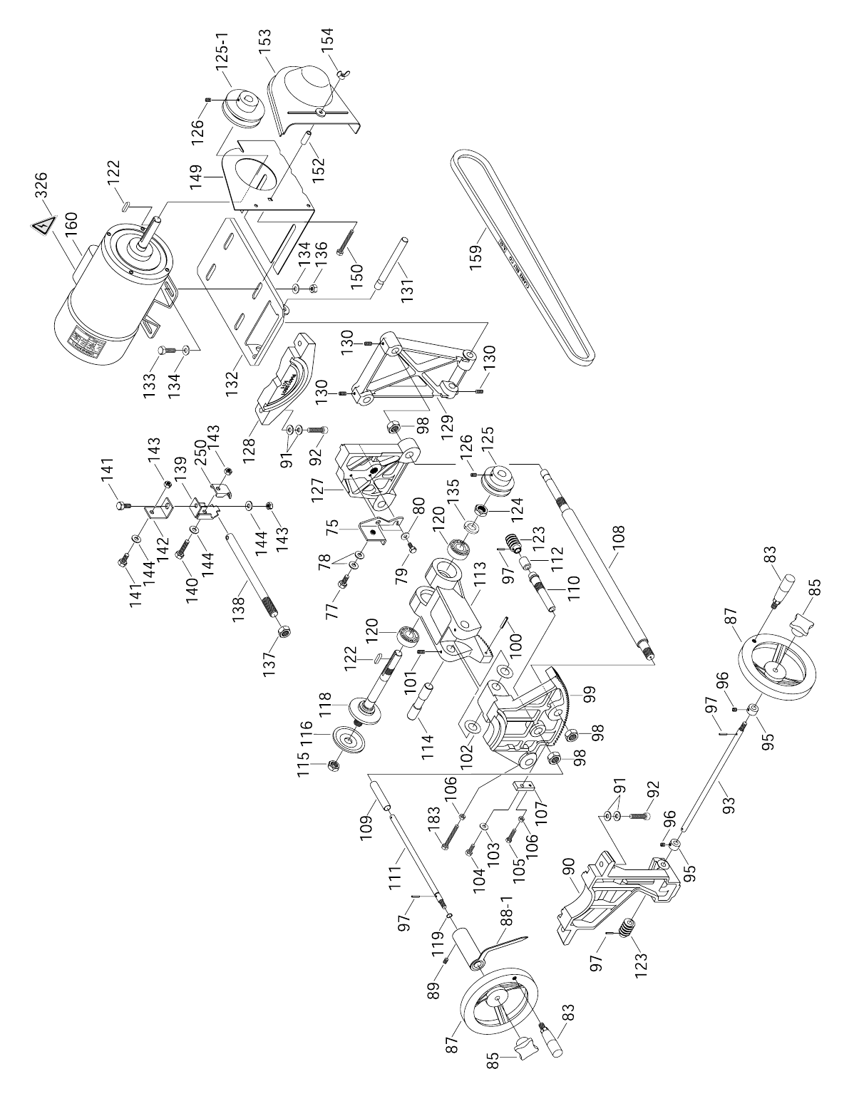
G1022Z
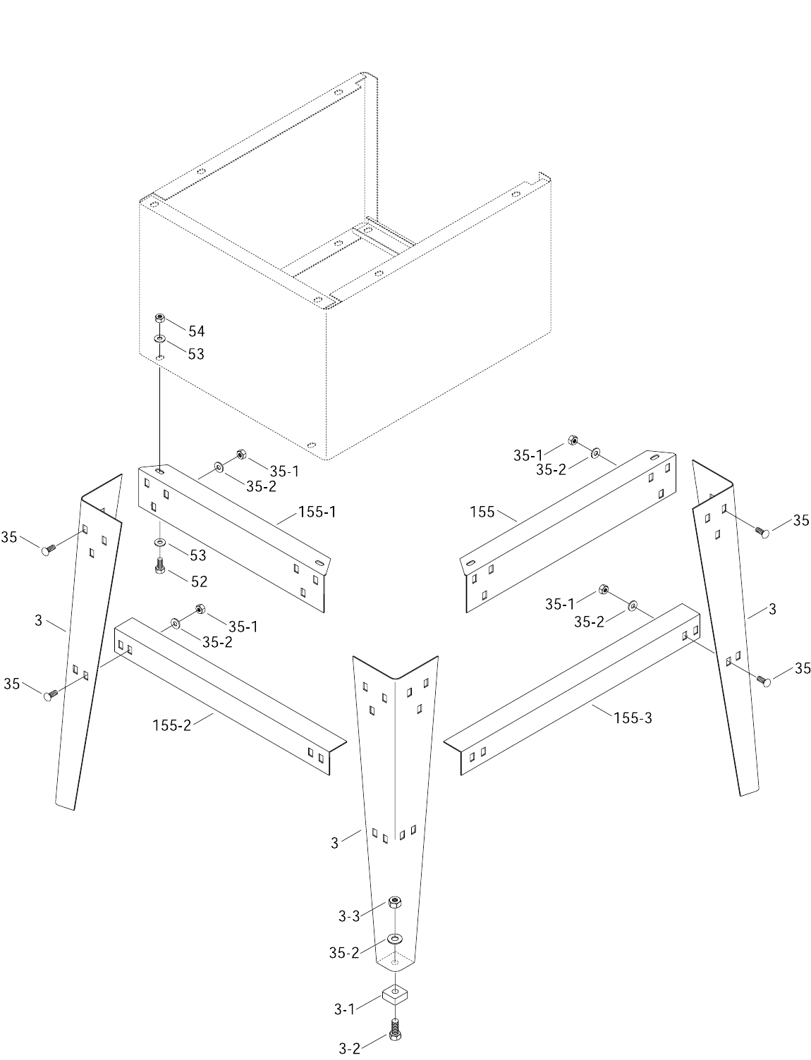
G1022Z

-66- G1022 Series Table Saws
REF PART # DESCRIPTION
41 P1022041 SHAFT FOR ECCENTRIC
42 P1022042 SHAFT FOR CLAMP
43 P1022Z043 LOCK LEVER
44-1 P1022044-1 PINION W/ KNOB
45 P1022045 CLAMP SHOE
46 P1022046 ADJUSTING BOLT
47 P1022047 SHAFT BUSHING
48 PSS02M SET SCR M6-1.0 x 6
49 P1022049 SPRING
51 P1022051 SPRING
52 PB03M HEX BOLT M8-1.25 x 16
53 PW01M FLAT WASHER 8MM
54 PN03M HEX NUT M8-1.25
55 PSB52M CAP SCR M8-1.25 x 10
56 PW01M FLAT WASHER 8MM
57 P1022057 BLOCK
58 P1022058 PIN
59 P1022059 SPRING
60 P1022060 CLAMP HOOK
61 P1022061 LEVER
62 P1022062 LOCK LINK
63 PS05M PHLP HD SCR M5-0.8 x 8
64 P1022Z064 FENCE
73C P1022073C SPLITTER
74 PRP20M ROLL PIN 4 x 22
75 P1022075 BRACKET
77 PB03M HEX BOLT M8-1.25 x 16
78 PW01M FLAT WASHER 8MM
79 PB02M HEX BOLT M6-1.0 x 12
80 PW03M FLAT WASHER 6MM
83 P1022083 HANDLE
85 P1022085 KNOB
87 P1022087 HANDWHEEL
88-1 P1022088-1 POINTER ASSEMBLY
89 PSS03M SETSCREW M6-1.0 x 8
90 P1022090 FRONT BRACKET
91 PW01M FLAT WASHER 8MM
92 PSB13M CAP SCR M8-1.25 x 30
93 P1022093 ANGLE WORM SHAFT
95 P1022095 COLLAR
96 PSS02M SETSCREW M6-1.0 x 6
97 PRP02M ROLL PIN 3 x 16
98 PN05M HEX NUT M16-1.5
99 P1022099 FRONT TRUNNION
REF PART # DESCRIPTION
1P1022001 TABLE INSERT
1A P1022001-A DADO INSERT
2PSS04M SETSCREW M6-1.0 x 12
3A P1022Z003A STAND LEG
3-1 P1022003-1 FOOT
3-2 PB32M HEX BOLT M10-1.5 x 25
3-3 PN02M HEX NUT M10-1.5
4P1022004 TABLE
5G1193 EXTENSION WING
6PW04M FLAT WASHER 10MM
7PB01M HEX BOLT M10-1.5 x 30
8P1022Z008 FRONT GUIDE RAIL
9P1022009 REAR GUIDE RAIL
10 P1022010 SPECIAL RAIL BOLT
10-1 PW04M FLAT WASHER 10MM
10-2 PN02M HEX NUT M10-1.5
11 P1022011 RAIL SPACER
12 P1022012 GUIDE RAIL PLUG
13 P1022013 CABINET
14 P1022014 GEAR BRACKET
15 PB03M HEX BOLT M8-1.25 x 16
16 PW01M FLAT WASHER 8MM
17 PN03M HEX NUT M8-1.25
18 P1022018 TILTING SCALE
19 P1022SM019 LOGO PLATE
20 PB03M HEX BOLT M8-1.25 x 16
21 PW01M FLAT WASHER 8MM
22 P1022Z022 MITER BODY
24 PN04M HEX NUT M4-0.7
25 PS01M PHLP HD SCR M4 - 0.7 x 18
26 P1022026 HAND KNOB
27 P1022SM027 FIBER WASHER
29 P1022029 MITER BAR
29-1 P1022029-1 T-SLOT WASHER
29-2 PFH04M FLAT HD SCR M6-1.0 x 8
30 P1022030 ANGLE POINTER
31 PSS02M SETSCREW M6-1.0 x 6
33 P1022033 STOP LINK
35 PCB01M CARR. BOLT M8-1.25 x 20
35-1 PN03M HEX NUT M8-1.25
35-2 PW01M FLAT WASHER 8MM
37 P1022Z037 WIDTH POINTER
38 P1022038 FENCE ADJUSTER
39 P1022Z039 FRONT CLAMP
40 P1022040 ECCENTRIC
G1022Z PARTS LIST

G1022 Series Table Saws -67-
REF PART # DESCRIPTION
REF PART # DESCRIPTION
100 PRP06M ROLL PIN 5 X 24
101 PSS04M SET SCR M6 - 1.0 x 12
102 P1022102 WAVY WASHER
103 PW03M FLAT WASHER 6MM
104 PB08M HEX BOLT M6-1.0 x 20
105 PB10M HEX BOLT M6-1.0 x 25
106 PN01M HEX NUT M6-1.0
107 P1022107 SET PLATE
108 P1022108 LINKING BAR
109 P1022109 SPACER
110 P1022110 ECCENTRIC SLEEVE
111 P1022111 WORM SHAFT
112 P1022112 SPACER
113 P1022113 ARBOR BRACKET
114 P1022114 ARBOR BRACKET PIN
115 P1022115 ARBOR NUT
116 P1022116 FLANGE
118 P1022118 BLADE ARBOR
120 P6203 BEARING 6203-2RS
122 PK01M KEY 5 x 5 x 22M
123 P1022123 WORM
124 P1022124 HEX NUT M17
125 P1022125 SPINDLE PULLEY
125-1 P1022125-1 MOTOR PULLEY
126 PSS03M SETSCREW M6-1.0 x 12
127 P1022127 REAR TRUNNION
128 P1022128 REAR BRACKET
129 P1022129 MOTOR BRACKET
130 PSS04M SETSCREW M6-1.0 x 12
131 P1022131 MOTOR PLATE ROD
132 P1022132 MOTOR PLATE
133 PB07M HEX BOLT M8-1.25 x 25
134 PW01M FLAT WASHER 8MM
135 PLW06 LOCK WASHER 5⁄8"
136 PN03M HEX NUT M8-1.25
137 PN05M HEX NUT M16-1.5
138 P1022138 SHAFT
139 P1022139 BRACKET
140 PB26M HEX BOLT M8-1.25 x 30
141 PB03M HEX BOLT M8-1.25 x 16
142 P1022142 CONNECTING PLATE
143 PN03M HEX NUT M8-1.25
144 PW01M FLAT WASHER 8MM
145 P1022145A SWITCH BRACKET
146 P1022146 SWITCH
147 PWRCRD110S POWER CORD
147-1 PWRCRD110L MOTOR CORD
148 P1022148 SPANNER WRENCH
149 P1022149 PULLEY GUARD BRACKET
150 PB10 HEX BOLT 1⁄4"-20 x 2"
152 P1022152 SLEEVE
153 P1022153 PULLEY COVER
154 PWN02 WING NUT 1⁄4"-20
155 P1022Z155 UPPER BRACKET - LONG
155-1 P1022Z155-1 UPPER BRACKET - SHORT
155-2 P1022Z155-2 LOWER BRACKET - SHORT
155-3 P1022Z155-3 LOWER BRACKET - LONG
156 P1022156 WIRE CLAMP
157 PS08M PHLP HD SCR M5-0.8 x 12
158 PN06M HEX NUT M5-0.8
159 PVA43 V-BELT A-43
160 G2535 MOTOR 11⁄2HP
161 P1022Z161 STRAIN RELIEF (Not Shown)
162 P1022Z162 SUPPORTING ARM
163 P1022Z163 RETAINER
164 P1022069 PRAWL
166 P1022Z166 PIN
167 P1022164 SPACER
171 PB47M HEX BOLT M6-1.0 x 40
173 P1022Z173 PIVOT PIN
174 P1022Z174 GUARD
175 P1022Z175 RETAINER
176 P1022068 SPRING
179 PLN03M LOCK NUT M6-1.0
180 PN02M HEX NUT M10-1.5
181 P1022Z181 SWITCH GUARD
182 PS02M PHLP HD SCR M4-0.7 X 12
183 PB39M HEX BOLT M6-1.0 x 50
185 PN01M HEX NUT M6-1.0
186 G3121 SCALE
187 P1022Z187 SPACER
188 PFH08M FLAT HD SCR M8-1.25 x 12
250 P1022Z250 CLAMP
251 PS05M PHLP HD SCR M5-0.8 X 8
252 P1022Z252 SPRING W/ CLIP
325 P1022SM325 WARNING LABEL
326 P1022SM326 ELECTRICITY LABEL
327 P1022SM327 SAFETY GLASSES LABEL
328 P1022Z328 MACHINE ID LABEL
329 P1022SM329 BLADE GUARD LABEL
G1022Z PARTS LIST

-68- G1022 Series Table Saws
Design Type ......................................................................................................Floor Model
Overall Dimensions:
Table Height ............................................................................................................37"
Table Size ........................................................................................271⁄8" D x 201⁄8" W
Table Size With Extension Wings ....................................................271⁄8" D x 405⁄8" W
Overall Dimensions – With Wings and Fence Rails ............................50" D x 521⁄2" W
Miter Gauge T-Slot ............................................................................................3⁄8" x 3⁄4"
Blade Tilt ....................................................................................................0°-45° Right
Weight (Net) ......................................................................................................325 lbs.
Weight (Shipping)..............................................................................................340 lbs.
Box # 1 Size (Base)..............................................................371⁄2" L x 22" W x 221⁄2" H
Box # 2 Size (Fence) ................................................................49" L x 151⁄2" W x 9" H
Box # 3 Size (Accessories) ..........................................................14" L x 14" W x 6" H
Box # 4 Size (Motor) ..............................................................101⁄4" L x 16" W x 93⁄4" H
Footprint ........................................................................................................21" x 25"
Construction:
Table ................................................................................................Ground Cast Iron
Stand ..................................................................................................Pre-formed Steel
Miter Gauge ......................................................Cast Iron ⁄ Steel; Adjusts for Side Play
Trunnions ........................................................................................................Cast Iron
Bearings............................................................Shielded and Lubricated Ball Bearings
Fence ....................................SHOP FOX®Heavy-Duty (PROZ: SHOP FOX®Classic
Guard ........................................................................................Steel and Clear Plastic
Wings..................................................................................Precision-Ground Cast Iron
Cutting Capacity:
Maximum Blade Diameter ........................................................................................10"
Maximum Depth of Cut at 90° ................................................................................31⁄8"
Maximum Depth of Cut at 45° ................................................................................21⁄8"
Maximum Rip to Right of Blade (Standard)..............................................................25"
Maximum Rip to Right of Blade (Optional Extension Rails) ....................................48"
Maximum Rip to Left of Blade ..................................................................................11"
Distance from Front of Table to Center of Blade ..................................................171⁄4"
Distance from Front of Table to Front of Blade ....................................................121⁄2"
Maximum Width of Dado Cut ..................................................................................13⁄16"
Motor: ZF ZFX PROZ PROZX
Type...................................................TEFC Capacitor Start Induction............................
Horsepower.......11⁄2HP....................2 HP......................2 HP.........................2 HP........
Phase / Cycle................................................Single Phase ⁄ 60 HZ.................................
Voltage................................................................110 ⁄ 220V............................................
Prewired.............110V.......................220V......................220V........................220V.......
Amps................17 ⁄ 8.5A.................26 / 13A...............26 / 13A................... .26 / 13A....
RPM...................................................................3450 RPM.............................................
Power Transfer.......................................Power Twist® Link Belt Drive...........................
Switch...........................................................ON/OFF Push Button.................................
Arbor:
Dimension........................................................................................................5⁄8" x 11⁄4"
Speed ..........................................................................................................4,700 RPM
Features:
........................................Includes Table Inserts for Standard Blade and Dado Blade
......................................U.S.A. Motor, 4" Ported Dust Hood, Link Belt, Rail Mounted Switch
Specifications, while deemed accurate, are not guaranteed.
Customer Service #: (570) 546-9663 • To Order Call: (800) 523-4777 • Fax #: (800) 438-5901
GRIZZLY MODELS G1022ZF, ZFX, PROZ, & PROZX
MACHINE DATA
SHEET
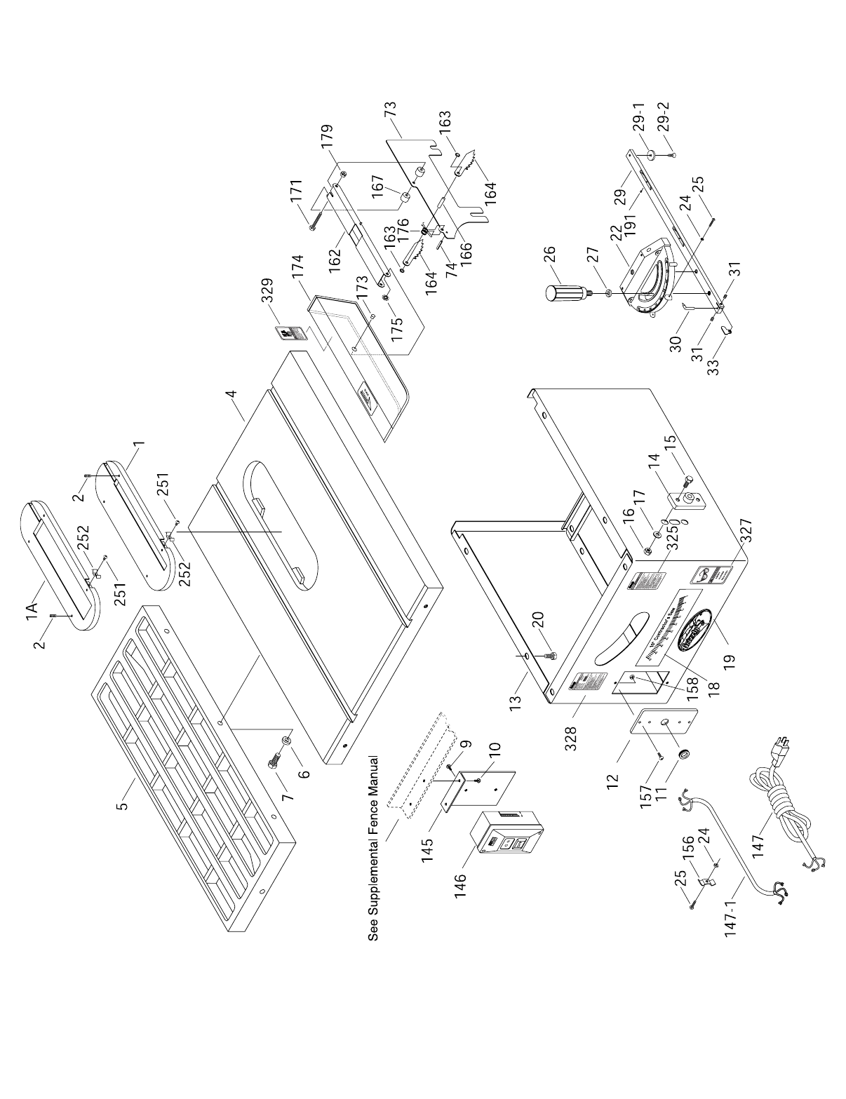
G1022ZF, ZFX, PROZ, & PROZX
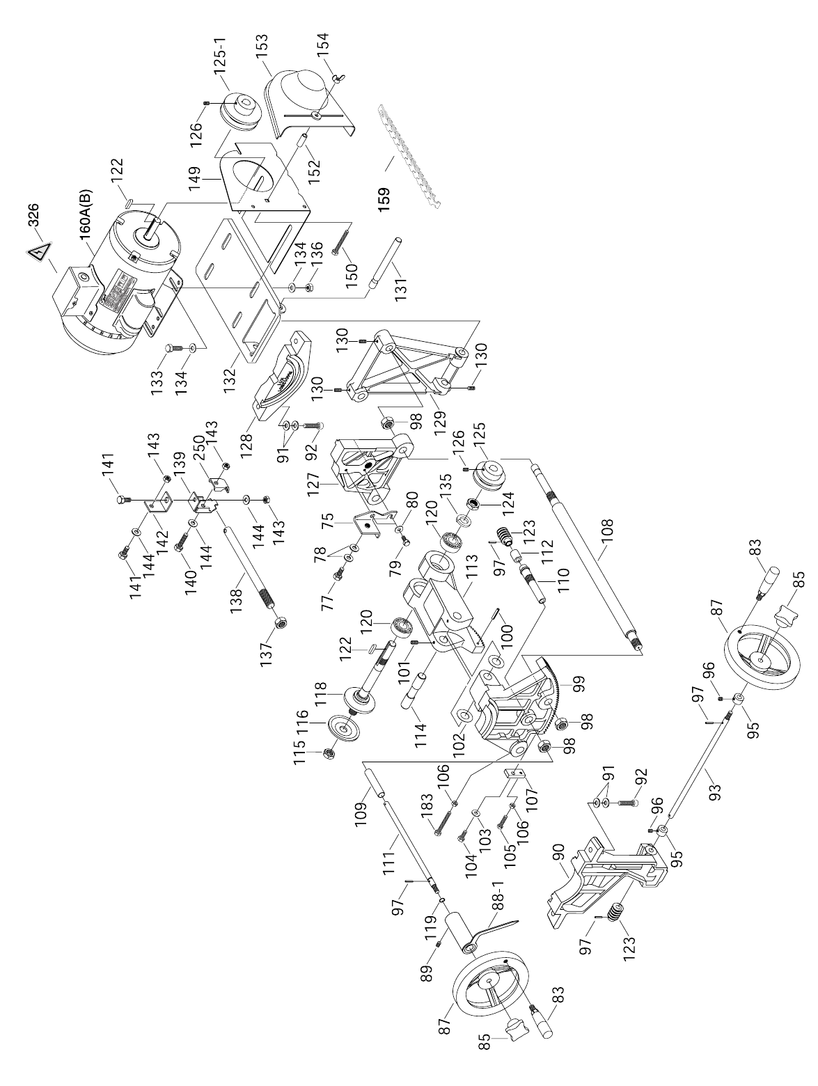
G1022ZF, ZFX, PROZ, & PROZX

G1022ZF, ZFX, PROZ, & PROZX

-72- G1022 Series Table Saws
REF PART # DESCRIPTION
77 PB03M HEX BOLT M8-1.25 x 1678
PW01M FLAT WASHER 8MM
79 PB02M HEX BOLT M6-1.0 x 12
80 PW03M FLAT WASHER 6MM
83 P1022083 HANDLE
85 P1022085 KNOB
87 P1022087 HANDWHEEL
88-1 P1022088-1 POINTER ASSEMBLY
89 PSS03M SETSCREW M6-1.0 x 8
90 P1022090 FRONT BRACKET
91 PW01M FLAT WASHER 8MM
92 PSB13M CAP SCR M8-1.25 x 30
93 P1022093 ANGLE WORM SHAFT
95 P1022095 COLLAR
96 PSS02M SETSCREW M6-1.0 x 6
97 PRP02M ROLL PIN 3 x 16
98 PN05M HEX NUT M16-1.5
99 P1022099 FRONT TRUNNION
100 PRP06M ROLL PIN 5 X 24
101 PSS04M SET SCR M6 - 1.0 x 12
102 P1022102 WAVY WASHER
103 PW03M FLAT WASHER 6MM
104 PB08M HEX BOLT M6-1.0 x 20
105 PB10M HEX BOLT M6-1.0 x 25
106 PN01M HEX NUT M6-1.0
107 P1022107 SET PLATE
108 P1022108 LINKING BAR
109 P1022109 SPACER
110 P1022110 ECCENTRIC SLEEVE
111 P1022111 WORM SHAFT
112 P1022112 SPACER
113 P1022113 ARBOR BRACKET
114 P1022114 ARBOR BRACKET PIN
115 P1022115 ARBOR NUT
116 P1022116 FLANGE
118 P1022118 BLADE ARBOR
120 P6203 BEARING 6203-2RS
122 PK01M KEY 5 x 5 x 22M
123 P1022123 WORM
124 P1022124 HEX NUT M17
125 P1022125 SPINDLE PULLEY
125-1 P1022125-1 MOTOR PULLEY
126 PSS03M SETSCREW M6-1.0 x 12
127 P1022127 REAR TRUNNION
128 P1022128 REAR BRACKET
129 P1022129 MOTOR BRACKET
130 PSS04M SETSCREW M6-1.0 x 12
131 P1022131 MOTOR PLATE ROD
132 P1022132 MOTOR PLATE
REF PART # DESCRIPTION
1P1022ZF001 TABLE INSERT
1A P1022001-A DADO INSERT
2PSS04M SETSCREW M6-1.0 x 12
3A P1022Z003A STAND LEG
3-1 P1022003-1 FOOT
3-2 PB32M HEX BOLT M10-1.5 x 25
3-3 PN02M HEX NUT M10-1.5
4P1022ZF004 TABLE
5* G1193 EXTENSION WING (*G1022ZF/ZFX)
5* P1022PROZ005 EXTENSION WING (*G1022PROZ)
5* P1022PROZX005 EXTENSION WING (*G1022PROZX)
6PW04M FLAT WASHER 10MM
7PB01M HEX BOLT M10-1.5 x 30
9P1022ZF009 SPECIAL SCR
10 P1022ZF010 SPECIAL SCR
11 P1022ZF011 RUBBER GROMMET
12 P1022ZF012 SWITCH CORD PLATE
13 P1022013 CABINET
14 P1022014 GEAR BRACKET
15 PB03M HEX BOLT M8-1.25 x 16
16 PW01M FLAT WASHER 8MM
17 PN03M HEX NUT M8-1.25
18 P1022018 TILTING SCALE
19 P1022SM019 PLATE LOGO
20 PB03M HEX BOLT M8-1.25 x 16
21 PW01M FLAT WASHER 8MM
22 P1022022 MITER BODY
24 PN04M HEX NUT M4-0.7
25 PS01M PHLP HD SCR M4 - 0.7 x 18
26 P1022026 HAND KNOB
27 P1022SM027 FIBER WASHER
29 P1022ZF029 ADJUSTABLE MITER BAR
29-1 P1022029-1 T-SLOT WASHER
29-2 PFH04M FLAT HD SCR M6-1.0 x 8
30 P1022030 ANGLE POINTER
31 PSS02M SETSCREW M6-1.0 x 6
33 P1022033 STOP LINK
35 PCB01M CARR. BOLT M8-1.25 x 20
35-1 PN03M HEX NUT M8-1.25
35-2 PW01M FLAT WASHER 8MM
36 PB68 HEX BOLT 10-24 X 3⁄8"
37 PW03 LOCK WASHER #10
38 PN25 HEX NUT 10-24
52 PB03M HEX BOLT M8-1.25 x 16
53 PW01M FLAT WASHER 8MM
54 PN03M HEX NUT M8-1.25
73C P1022073C SPLITTER
74 PRP20M ROLL PIN 4 x 22
75 P1022075 BRACKET
G1022ZF, ZFX, PROZ, & PROZX PARTS LIST

G1022 Series Table Saws -73-
REF PART # DESCRIPTION
250 P1022Z250 CLAMP
251 PS05M PHLP HD SCR M5-0.8 X 8
252 P1022Z252 SPRING
325 P1022SM325 WARNING LABEL
326 P1022SM326 ELECTRICITY LABEL
327 P1022SM327 SAFETY GLASSES LABEL
328* P1022ZF328 MACHINE ID LABEL (*G1022ZF)
328* P1022ZFX328 MACHINE ID LABEL (*G1022ZFX)
328* P1022PROZ328 MACHINE ID LABEL (*G1022PROZ)
328* P1022PROZX328 MACHINE ID LABEL (*G1022PROZX)
329 P1022SM329 BLADE GUARD LABEL
REF PART # DESCRIPTION
133 PB07M HEX BOLT M8-1.25 x 25
134 PW01M FLAT WASHER 8MM
135 PLW06 LOCK WASHER 5⁄8"
136 PN03M HEX NUT M8-1.25
137 PN05M HEX NUT M16-1.5
138 P1022138 SHAFT
139 P1022139 BRACKET
140 PB26M HEX BOLT M8-1.25 x 30
141 PB03M HEX BOLT M8-1.25 x 16
142 P1022142 CONNECTING PLATE
143 PN03M HEX NUT M8-1.25
144 PW01M FLAT WASHER 8MM
145 P1022ZF145 SWITCH L-BRACKET
146 P1022ZF146 SWITCH
147 PWRCRD110S POWER CORD
147-1 PWRCRD110L MOTOR CORD
148 P1022148 SPANNER WRENCH
149 P1022149 PULLEY GUARD BRACKET
150 PB10 HEX BOLT 1⁄4"-20 x 2"
152 P1022152 SLEEVE
153 P1022153 PULLEY COVER
154 PWN02 WING NUT 1⁄4"-20
155 P1022Z155 UPPER BRACKET - LONG
155-1 P1022Z155-1 UPPER BRACKET - SHORT
155-2 P1022Z155-2 LOWER BRACKET - SHORT
155-3 P1022Z155-3 LOWER BRACKET - LONG
156 P1022156 WIRE CLAMP
157 PS08M PHLP HD SCR M5-0.8 x 12
158 PN06M HEX NUT M5-0.8
159 P1022ZF159 POWER TWIST BELT
160A G5009 1.5 HP USA MOTOR
160B G4192 2.0 HP USA MOTOR
161 P1022161 STRAIN RELIEF (Not Shown)
162 P1022Z162 SUPPORTING ARM
163 P1022Z163 RETAINER
164 P1022069 PRAWL
166 P1022Z166 PIN
167 P1022164 SPACER
171 PB47M HEX BOLT M6-1.0 x 40
173 P1022Z173 PIVOT PIN
174 P1022Z174 GUARD
175 P1022Z175 RETAINER
176 P1022068 SPRING
179 PLN03M LOCK NUT M6-1.0
180 PN02M HEX NUT M10-1.5
182 PS02M PHLP HD SCR M4-0.7 X 12
183 PB39M HEX BOLT M6-1.0 x 50
189 P1022ZF189 DUST PORT ADAPTER
190 P1022ZF190 DUST PORT
G1022ZF, ZFX, PROZ, & PROZX PARTS LIST

-74- G1022 Series Table Saws
SYMPTOM
Motor will not start.
Motor will not start; fuses or
circuit breakers blow.
Motor overheats.
Motor stalls (resulting in
blown fuses or tripped cir-
cuit).
Machine slows when oper-
ating.
Loud, repetitious noise com-
ing from machine.
Blade is not square w/miter
slot or fence is not square to
blade.
Fence hits table top when
sliding on to the table.
Blade does not reach 90°.
Blade hits insert at 45°.
Blade won’t go beneath
table surface.
Hand wheels won’t turn.
POSSIBLE CAUSE
1. Low voltage.
2. Open circuit in motor or loose con-
nections.
1. Short circuit in line cord or plug.
2. Short circuit in motor or loose con-
nections.
3. Incorrect fuses or circuit breakers in
power line.
1. Motor overloaded.
2. Air circulation through the motor
restricted.
1. Short circuit in motor or loose con-
nections.
2. Low voltage.
3. Incorrect fuses or circuit breakers in
power line.
4. Motor overloaded.
Applying too much pressure to work-
piece.
1. Pulley setscrews or keys are missing
or loose.
2. Motor fan is hitting the cover.
3. V-belts are defective
1. Blade is warped.
2. Table top is not parallel to blade.
3. Fence is not parallel to blade.
1. Front rail is bolted too low on the
table.
2. Rear rail is bolted too low on the
table.
1. 90° stop bolt is out of adjustment.
2. Pointer bracket is hitting before the
blade reaches 90°.
1. Hole in insert is inadequate.
2. Table out of alignment.
3. Blade position is incorrect.
Table top too low.
1. Hand wheel key is inserted too far.
2. Bullets are wedged.
3. Roll pin or setscrew in worm gear is
contacting geared trunnion.
CORRECTIVE ACTION
1. Check power line for proper voltage.
2. Inspect all lead connections on motor for loose or open con-
nections.
1. Inspect cord or plug for damaged insulation and shorted wires.
2. Inspect all connections on motor for loose or shorted terminals
or worn insulation.
3. Install correct fuses or circuit breakers.
1. Reduce load on motor.
2. Clean out motor to provide normal air circulation.
1. Inspect connections on motor for loose or shorted terminals or
worn insulation.
2Correct the low voltage conditions.
3. Install correct fuses or circuit breakers.
4. Reduce load on motor.
Feed workpiece slower.
1. Inspect keys and setscrews. Replace or tighten if necessary.
2. Tighten fan or shim cover.
3. Replace V-belts. See Maintenance.
1. Replace blade.
2. Make table parallel to blade. See Adjustments.
3. Make fence parallel to blade. See Adjustments.
1. Raise front rail.
2. Raise rear rail.
1. Adjust 90° stop bolt. See Adjustments.
2. File down the right side of the pointer bracket until the blade
can reach 90°.
1. File or mill the hole in the insert.
2. Align table. See Adjustments.
3. Adjust blade position. See Adjustments.
Raise table top w/washers.
1. Remove hand wheel and adjust key.
2. Remove hand wheel and adjust bullets.
3. Inspect roll pins and setscrews in the worm gear. Tighten if
necessary.
TROUBLESHOOTING GUIDE
Disconnect the machine
power cord during
adjustments. Failure to
follow this warning
could result in serious
personal injury or death.
!

G1022 Series Table Saws -75-
PUSH STICK
MAKE FROM 1⁄2'' OR 3⁄4''
WOOD OR THICKNESS
LESS THAN WIDTH OF
MAT'L TO BE CUT
CAUTION
USE ONLY GOOD
STRONG WOOD OR
PLYWOOD
1⁄2'' GRID
CUT HERE TO
PUSH 1⁄2'' WOOD
CUT HERE TO
PUSH 1⁄4'' WOOD
NOTCH TO HELP
PREVENT HAND
FROM SLIPPING

-76- G1022 Series Table Saws
Notes

G1022 Series Table Saws -77-
Notes

-78- G1022 Series Table Saws
Grizzly Industrial, Inc. warrants every product it sells for a period of 1 year to the original purchaser from
the date of purchase. This warranty does not apply to defects due directly or indirectly to misuse, abuse,
negligence, accidents, repairs or alterations or lack of maintenance. This is Grizzly’s sole written warranty
and any and all warranties that may be implied by law, including any merchantability or fitness, for any par-
ticular purpose, are hereby limited to the duration of this written warranty. We do not warrant or represent
that the merchandise complies with the provisions of any law or acts unless the manufacturer so warrants.
In no event shall Grizzly’s liability under this warranty exceed the purchase price paid for the product and
any legal actions brought against Grizzly shall be tried in the State of Washington, County of Whatcom.
We shall in no event be liable for death, injuries to persons or property or for incidental, contingent, spe-
cial, or consequential damages arising from the use of our products.
To take advantage of this warranty, contact us by mail or phone and give us all the details. We will then
issue you a “Return Number,’’ which must be clearly posted on the outside as well as the inside of the car-
ton. We will not accept any item back without this number. Proof of purchase must accompany the mer-
chandise.
The manufacturers reserve the right to change specifications at any time because they constantly strive to
achieve better quality equipment. We make every effort to ensure that our products meet high quality and
durability standards and we hope you never need to use this warranty.
Please feel free to write or call us if you have any questions about the machine or the manual.
Thank you again for your business and continued support. We hope to serve you again soon.
WARRANTY AND RETURNS

10. Which benchtop tools do you own? Check all that apply.
___1" x 42" Belt Sander ___6" - 8" Grinder
___5" - 8" Drill Press ___Mini Lathe
___8" Table Saw ___10" - 12" Thickness Planer
___8" - 10" Bandsaw ___Scroll Saw
___Disc/Belt Sander ___Spindle/Belt Sander
___Mini Jointer
___Other__________________________________________________
11. How many of the machines checked above are Grizzly? ____________
12. Which portable/hand held power tools do you own? Check all that apply.
___Belt Sander ___Orbital Sander
___Biscuit Joiner ___Palm Sander
___Circular Saw ___Portable Planer
___Detail Sander ___Saber Saw
___Drill/Driver ___Reciprocating Saw
___Miter Saw ___Router
___Other__________________________________________________
13. What machines/supplies would you like Grizzly Industrial to carry?
__________________________________________________________
__________________________________________________________
14. What new accessories would you like Grizzly Industrial to carry?
__________________________________________________________
__________________________________________________________
15. What other companies do you purchase your tools and supplies from?
__________________________________________________________
__________________________________________________________
16. Do you think your purchase represents good value?
___Yes ___No
17. Would you recommend Grizzly Industrial to a friend?
___Yes ___No
18. Would you allow us to use your name as a reference for Grizzly customers
in your area? Note: We never use names more than three times.
___Yes ___No
19. Comments:_________________________________________________
__________________________________________________________
__________________________________________________________
__________________________________________________________
__________________________________________________________
1. How did you learn about us?
___Advertisement ___Friend
___Catalog ___Card Deck
___World Wide Web
___Other__________________________________________________
2. Which of the following magazines do you subscribe to.
___American Woodworker ___Practical Homeowner
___Cabinetmaker ___Shop Notes
___Family Handyman ___Today’s Homeowner
___Fine Homebuilding ___WOOD
___Fine Woodworking ___Wooden Boat
___Home Handyman ___Woodshop News
___Journal of Light Construction ___Woodsmith
___Old House Journal ___Woodwork
___Popular Mechanics ___Woodworker
___Popular Science ___Woodworker’s Journal
___Popular Woodworking ___Workbench
___Other__________________________________________________
3. Which of the following woodworking/remodeling shows do you watch?
___Backyard America ___The New Yankee Workshop
___Home Time ___This Old House
___The American Woodworker ___Woodwright’s Shop
___Other__________________________________________________
4. What is your annual household income?
___$20,000-$29,999 ___$60,000-$69,999
___$30,000-$39,999 ___$70,000-$79,999
___$40,000-$49,999 ___$80,000-$89,999
___$50,000-$59,999 ___$90,000 +
5. What is your age group?
___20-29 ___50-59
___30-39 ___60-69
___40-49 ___70 +
6. How long have you been a woodworker?
___0 - 2 Years ___8 - 20 Years
___2 - 8 Years ___20+ Years
7. How would you rank your woodworking skills?
___Simple ___Advanced
___Intermediate ___Master Craftsman
8. What stationary woodworking tools do you own? Check all that apply.
___Air Compressor ___Panel Saw
___Band Saw ___Planer
___Drill Press ___Power Feeder
___Drum Sander ___Radial Arm Saw
___Dust Collector ___Shaper
___Horizontal Boring Machine ___Spindle Sander
___Jointer ___Table Saw
___Lathe ___Vacuum Veneer Press
___Mortiser ___Wide Belt Sander
___Other__________________________________________________
9. How many of your woodworking machines are Grizzly? _____________
Name ____________________________________________________________________________________
Street ____________________________________________________________________________________
City ______________________________________________________________State________Zip_________
Phone Number_______________________E-Mail_______________________FAX________________________
MODEL # __________________________Order #______________________________________________
The following information is given on a voluntary basis. It will be used for marketing purposes to help us develop better products and services. Of
course, all information is strictly confidential.
WARRANTY CARD

FOLD ALONG DOTTED LINE
FOLD ALONG DOTTED LINE
GRIZZLY INDUSTRIAL, INC.
P.O. BOX 2069
BELLINGHAM, WA 98227-2069
TAPE ALONG EDGES--PLEASE DO NOT STAPLE
Name_______________________________
Street_______________________________
City______________State______Zip______
Send a Grizzly Catalog to a friend:


Buy Direct and Save with Grizzly® – Trusted, Proven and a Great Value!
-OR-
• SECURE ORDERING
• ORDERS SHIPPED WITHIN 24 HOURS
• E-MAIL RESPONSE WITHIN ONE HOUR
Visit Our Website Today And Discover Why
Grizzly® Is The Industry Leader!
Call Today For A
FREE
Full Color Catalog
