Grizzly T25920 User Manual To The Fd570611 C89e 4fc3 A549 163f145bde32
User Manual: Grizzly T25920 to the manual
Open the PDF directly: View PDF ![]() .
.
Page Count: 48

MODEL T25920/T25926
VARIABLE-SPEED WOOD
LATHE
OWNER'S MANUAL
(For models manufactured since 08/14)
COPYRIGHT © DECEMBER, 2014 BY GRIZZLY INDUSTRIAL, INC.
WARNING: NO PORTION OF THIS MANUAL MAY BE REPRODUCED IN ANY SHAPE
OR FORM WITHOUT THE WRITTEN APPROVAL OF GRIZZLY INDUSTRIAL, INC.
#AWWK17009 PRINTED IN CHINA
T25920
T25926
Table of Contents
INTRODUCTION ............................................... 3
Contact Info.................................................... 3
Manual Accuracy ........................................... 3
T25920 & T25926 Data Sheet ...................... 4
Identification ................................................... 6
Controls & Components ................................. 7
SECTION 1: SAFETY ....................................... 8
Safety Instructions for Machinery .................. 8
Additional Safety for Wood Lathes .............. 10
SECTION 2: POWER SUPPLY ...................... 11
SECTION 3: SETUP ....................................... 13
Unpacking .................................................... 13
Needed for Setup ......................................... 13
Inventory ...................................................... 14
Cleanup ........................................................ 14
Site Considerations ...................................... 15
Bench Mounting ........................................... 15
Assembly ..................................................... 16
Test Run ...................................................... 16
SECTION 4: OPERATIONS ........................... 17
Stock Inspection & Requirements................ 18
Adjusting Spindle Speeds ............................ 19
Adjusting Tailstock ....................................... 20
Adjusting Tool Rest ...................................... 21
Installing/Removing Headstock Center ........ 22
Installing/Removing Tailstock Center .......... 22
Removing/Installing Faceplate ..................... 23
Selecting Turning Tools ............................... 24
Spindle Turning ............................................ 25
Faceplate Turning ........................................ 27
Sanding/Finishing ........................................ 28
SECTION 5: ACCESSORIES ......................... 29
SECTION 6: MAINTENANCE ......................... 31
Schedule ...................................................... 31
Cleaning & Protecting .................................. 31
Lubrication ................................................... 31
SECTION 7: SERVICE ................................... 32
Troubleshooting ........................................... 32
Tensioning & Replacing Belt........................ 34
Replacing Fuse ............................................ 35
Replacing Brushes ....................................... 36
SECTION 8: WIRING ...................................... 37
Wiring Safety Instructions ............................ 37
T25920/T25926 Wiring Diagram .................. 38
SECTION 9: PARTS ....................................... 39
T25920 Breakdown ...................................... 39
T25920 Parts List ......................................... 40
T25926 Breakdown ...................................... 41
T25926 Parts List ......................................... 42
T25920/T25926 Labels & Cosmetics........... 43
WARRANTY & RETURNS ............................. 47

Model T25920/T25926 (Mfd. Since 08/14) -3-
INTRODUCTION
We are proud to provide a high-quality owner’s
manual with your new machine!
We
made every effort to be exact with the
instruc-
tions, specifications, drawings, and photographs
contained inside. Sometimes we make mistakes,
but
our policy of continuous improvement
also
means that
sometimes the machine
you receive
will be slightly different than what is shown in
the manual
.
If you find this to be the case, and the difference
between the manual and machine leaves you
confused about a procedure
, check our website
for an updated version. W
e post current
manuals
and
manual updates for free on our website at
www.grizzly.com
.
Alternatively, you can call our Technical Support
for help. Before calling, please write down the
Manufacture Date
and Serial Number
stamped
into the machine ID label (see below). This infor-
mation helps us determine if updated documenta-
tion is available for your machine.
Manufacture Date
Serial Number
Manual Accuracy
We stand behind our machines. If you have
any questions or need help, use the information
below to contact us. Before contacting, please get
the serial number and manufacture date of your
machine. This will help us help you faster.
Grizzly Technical Support
1203 Lycoming Mall Circle
Muncy, PA 17756
Phone: (570) 546-9663
Email: techsupport@grizzly.com
We want your feedback on this manual. What did
you like about it? Where could it be improved?
Please take a few minutes to give us feedback.
Grizzly Documentation Manager
P.O. Box 2069
Bellingham, WA 98227-2069
Email: manuals@grizzly.com
Contact Info

-4- Model T25920/T25926 (Mfd. Since 08/14)
MODELS T25920 & T25926
BENCHTOP LATHES
Model Number T25920 T25926
Product Dimensions
Weight 84 lbs. 75 lbs.
Width (side-to-side) x Depth
(front-to-back) x Height 38
3⁄4 x 12 X 17 in. 37
3⁄4 x 12 x 13 in.
Footprint (length x width) 30 x 8 in. 30 x 8 in.
Shipping Dimensions
Type Cardboard
Content Machine
Weight 89 lbs. 79 lbs.
Width (side-to-side) x Depth
(front-to-back) x Height 32 x 19 x 12 in. 33 x 17 x 13 in.
Must Ship Upright Yes
Electrical
Power Requirement 110V, Single-Phase, 60 Hz
Prewired Voltage 110V
Full-Load Current Rating 5.3A 6A
Minimum Circuit Size 15A
Connection Type Cord & Plug
Power Cord Included Yes
Switch Toggle Switch w/Disabling Key
Cord Length 6 ft.
Cord Gauge 18 AWG
Plug Included Yes
Included Plug Type NEMA 5-15
MODEL T24463, T24464
6" Bench Grinders
Model Number T24463 T24464
Product Dimensions
Weight 19 lbs. 17 lbs.
Width (side-to-side)/Depth (front-
to-back)/Height 7
1
⁄
2
" x 13
3
⁄
4
" x 9" 8
1
⁄
4
" x 14
3
⁄
4
" x 10
1
⁄
4
"
Foot Print (Width/Depth) 5" x 24" 5
1
⁄
2
" x 4
3
⁄
4
"
Shipping Dimensions
Type Cardboard
Weight 210 lbs.
Width (side-to-side)/Depth (front-
to-back)/Height 37" x 27" x 45"
Electrical
Power Requirement 110V or 220V, Single-Phase, 60 Hz
Full-Load Current Rating at 110V
(w/o 5" Restrictor) 18.8 Amp
Full-Load Current Rating at 110V
(w/ 5" Restrictor) 15.8 Amp
Full-Load Current Rating at 220V
(w/o 5" Restrictor) 9.4 Amps
Full-Load Current Rating at 220V
(w/ 5" Restrictor) 7.9 Amps
Switch Relay Switch w/ Circuit Breaker
Switch Voltage 110V/220V
Cord Length 10
1
⁄
2
ft.
Cord Gauge 12AWG
Recommended Circuit Size at
110V (w/o 5" Restrictor) 30 Amp
Recommended Circuit Size at
110V (w/ 5" Restrictor) 20 Amp
Recommended Circuit Size at
220V 15 Amp
Plug Included No
Recommended Plug Type at
110V (w/o 5" Restrictor) NEMA L5-30
Recommended Plug Type at
110V (w/ 5" Restrictor) NEMA 5-20
Model GXXXX/GXXXX/GXXXXPage 1 of 4
Motor
Type Universal Brush-Type Motor
Horsepower 550W (3⁄4 HP) 370W (1⁄2 HP)
Phase Single-Phase
Amps 5.3A 6A
Speed 1700 RPM
Bearings Shielded & Permanently Sealed
Power Transfer V-Belt
Model T25920/T25926Page 1 of 2
T25920 & T25926 Data Sheet

Model T25920/T25926 (Mfd. Since 08/14) -5-
Spindle Information
Spindle Taper MT#2
Spindle Thread Size 1 in.
Spindle TPI 8 TPI
Spindle Thread Direction Right Hand
Spindle Bore Through-Hole
11
⁄
16
in.
Type of Included Spindle Center Spur
Tailstock Information
Tailstock Taper MT#2
Tailstock Center Type Live
Tool Rest Information
Tool Rest Width 5
7
⁄
8
in. 5
3
⁄
4
in.
Tool Rest Post Diameter
5
⁄
8
in.
Tool Rest Post Length 3 in. 2
3
⁄
8
in.
Tool Rest Base Height 1
1
⁄
4
in. 1
3
⁄
8
in.
Construction
Headstock Cast Iron
Bed Cast Iron
Frame Cast Iron
Base Cast Iron
Tailstock Cast Iron
Paint Urethane
Other
Country of Origin China
Warranty 1 Year
Serial Number Location ID Label
ISO 9001 Factory Yes
Assembly Time 10 Minutes
Model Number T25920 T25926
Operation Information 12 in. 9
3
⁄
4
in.
Swing Over Bed 12 in. 9
3
⁄
4
in.
Dist. Between Centers 16
1
⁄
2
in. 16
3
⁄
4
in.
Bed Width 7
1
⁄
4
in.
Faceplate Size 3
1
⁄
8
in.
Swing Over Tool Rest Base 9
1
⁄
2
in. 7
1
⁄
4
in.
No. Of Spindle Speeds Variable
Spindle Speed Range 650 – 3800 RPM
Model T25920/T25926Page 2 of 2
-6- Model T25920/T25926 (Mfd. Since 08/14)
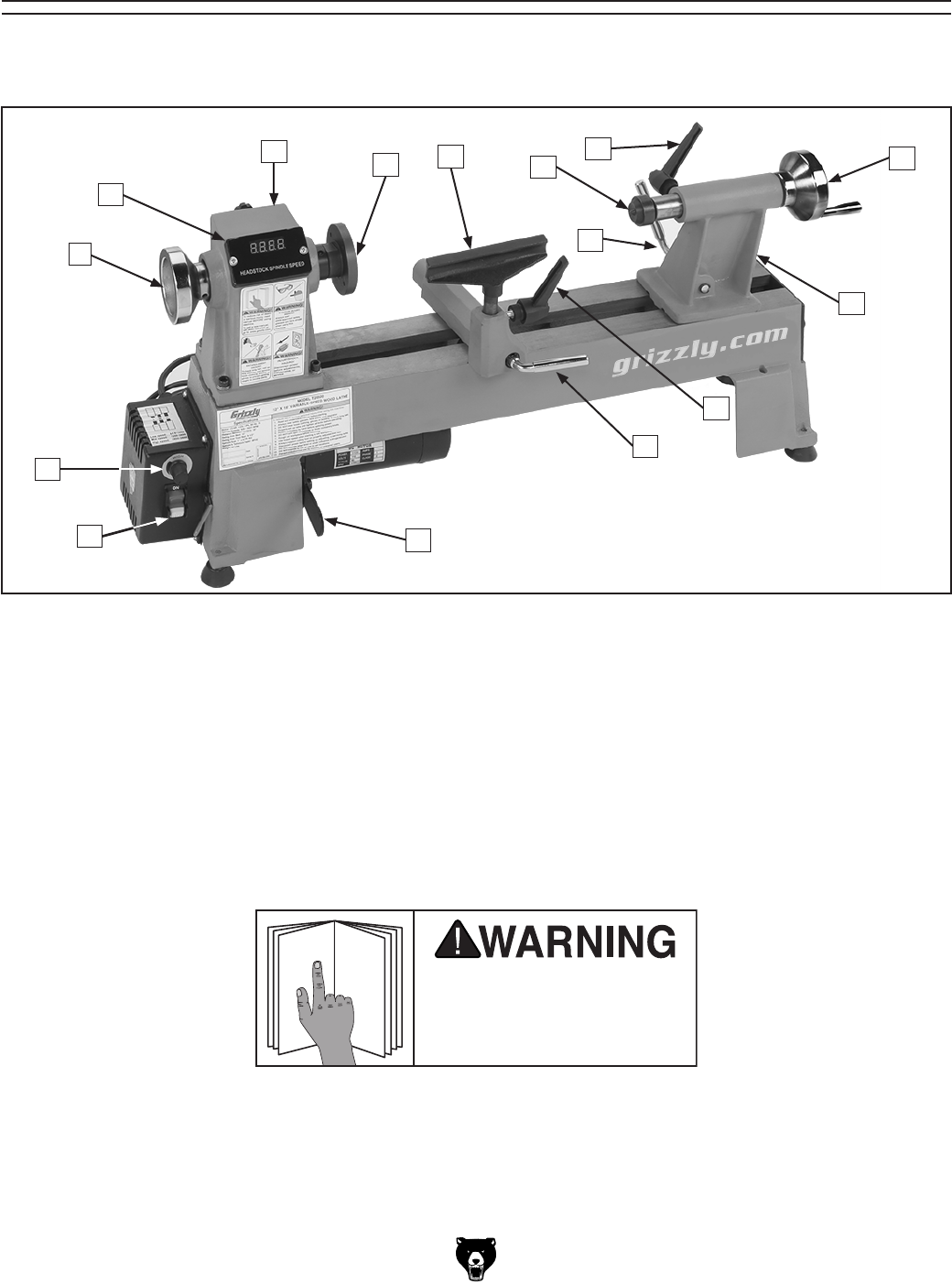
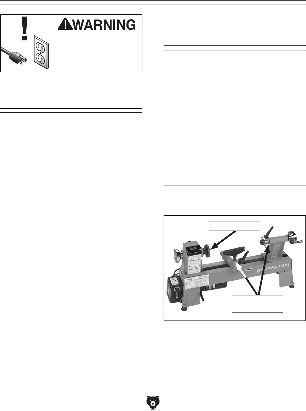
Figure 1. T25920/T25926 control and component identification.
A. Headstock
B. Faceplate
C. Tool Rest
D. Live Center
E. Tailstock Lock Lever
F. Quill Lock Lever
G. Quill Handwheel
H. Tailstock
Identification
AB
To reduce your risk of
serious injury, read this
entire manual BEFORE
using machine.
Become familiar with names and locations of controls and features shown below to better understand
instructions in this manual.
D
C
LK
H
G
E
I. Tool Rest Lock Lever
J. Base Lock Lever
K. Belt Tension Lever
L. Lathe ON/OFF Switch
M. Spindle Speed Dial
N. Headstock Handwheel
O. Digital Readout
F
M
I
J
N
O
Model T25920/T25926 (Mfd. Since 08/14) -7-
Controls &
Components
To reduce your risk of
serious injury, read this
entire manual BEFORE
using machine.
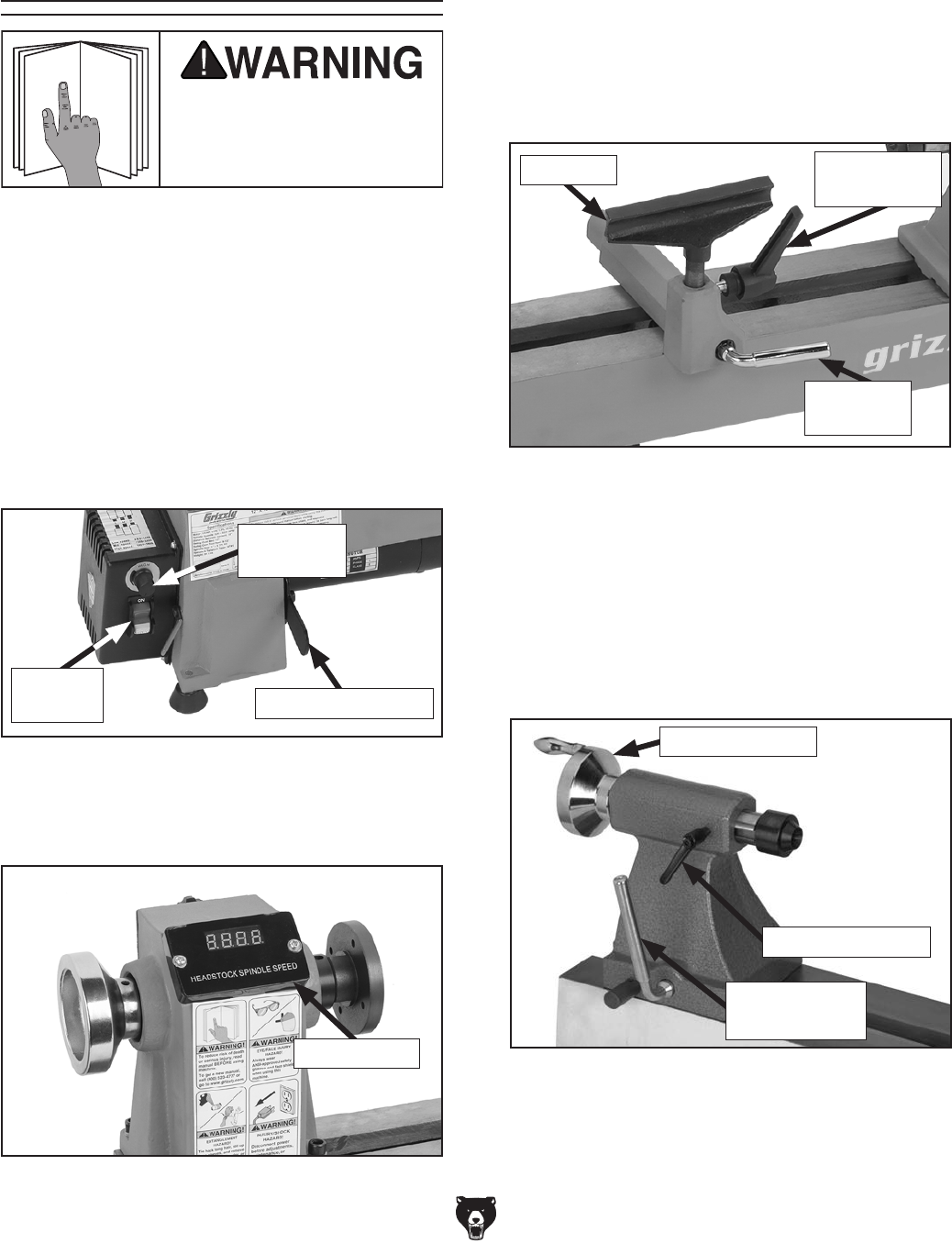
Figure 3. RPM display on headstock.
Use descriptions and figures below to become
familiar with basic controls of your lathe.
ON/OFF Switch: Turns power ON/OFF to lathe
motor, which rotates spindle.
Belt Tension Lever: Releases tension on belt to
change speeds or replace belt.
Spindle Speed Dial: Adjusts speed of the spindle
within current belt position speed range.
Figure 5. Typical tailstock controls.
Quill Handwheel: Moves quill in and out to allow
clamping or releasing of workpiece.
Quill Lock Lever: Locks quill in place to prevent
loosening during operation of lathe.
Tailstock Lock Lever: Unlocks tailstock to allow
quick position adjustments.
Quill Handwheel
Quill Lock Lever
Tailstock Lock
Lever
Figure 4. Tool rest control levers.
Tool Rest Tool Rest
Lock Lever
Base Lock
Lever
Tool Rest: Provides a stable resting position for
turning tools.
Tool Rest Lock Lever: Locks tool rest in position
relative to tool rest base.
Base Lock Lever: Lock and unlocks tool rest
base and allows it to be repositioned along lathe
bed.
Figure 2. Tension lever and ON/OFF switch.
ON/OFF
Switch Belt Tension Lever
Spindle
Speed Dial
RPM Display: Displays spindle speed in revolu-
tions per minute (RPM).
RPM Display

-8- Model T25920/T25926 (Mfd. Since 08/14)
ELECTRICAL EQUIPMENT INJURY RISKS. You
can be shocked, burned, or killed by touching live
electrical components or improperly grounded
machinery. To reduce this risk, only allow qualified
service personnel to do electrical installation or
repair work, and always disconnect power before
accessing or exposing electrical equipment.
DISCONNECT POWER FIRST.
Always discon-
nect machine from power supply BEFORE making
adjustments, changing tooling, or servicing machine.
This prevents an injury risk from unintended startup
or contact with live electrical components.
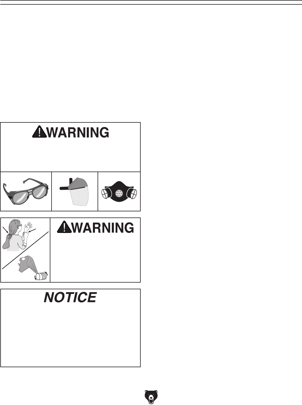
EYE PROTECTION. Always wear ANSI-approved
safety glasses or a face shield when operating or
observing machinery to reduce the risk of eye
injury or blindness from flying particles. Everyday
eyeglasses are NOT approved safety glasses.
OWNER’S MANUAL. Read and understand this
owner’s manual BEFORE using machine.
TRAINED OPERATORS ONLY. Untrained oper-
ators have a higher risk of being hurt or killed.
Only allow trained/supervised people to use this
machine. When machine is not being used, dis-
connect power, remove switch keys, or lock-out
machine to prevent unauthorized use—especially
around children. Make workshop kid proof!
DANGEROUS ENVIRONMENTS. Do not use
machinery in areas that are wet, cluttered, or have
poor lighting. Operating machinery in these areas
greatly increases the risk of accidents and injury.
MENTAL ALERTNESS REQUIRED. Full mental
alertness is required for safe operation of machin-
ery. Never operate under the influence of drugs or
alcohol, when tired, or when distracted.
For Your Own Safety, Read Instruction
Manual Before Operating This Machine
The purpose of safety symbols is to attract your attention to possible hazardous conditions.
This manual uses a series of symbols and signal words intended to convey the level of impor-
tance of the safety messages. The progression of symbols is described below. Remember that
safety messages by themselves do not eliminate danger and are not a substitute for proper
accident prevention measures. Always use common sense and good judgment.
Indicates a potentially hazardous situation which, if not avoided,
MAY result in minor or moderate injury. It may also be used to alert
against unsafe practices.
Indicates a potentially hazardous situation which, if not avoided,
COULD result in death or serious injury.
Indicates an imminently hazardous situation which, if not avoided,
WILL result in death or serious injury.
This symbol is used to alert the user to useful information about
proper operation of the machine.
NOTICE
Safety Instructions for Machinery
SECTION 1: SAFETY

Model T25920/T25926 (Mfd. Since 08/14) -9-
WEARING PROPER APPAREL. Do not wear
clothing, apparel or jewelry that can become
entangled in moving parts. Always tie back or
cover long hair. Wear non-slip footwear to avoid
accidental slips, which could cause loss of work-
piece control.
HAZARDOUS DUST. Dust created while using
machinery may cause cancer, birth defects, or
long-term respiratory damage. Be aware of dust
hazards associated with each workpiece material,
and always wear a NIOSH-approved respirator to
reduce your risk.
HEARING PROTECTION. Always wear hear-
ing protection when operating or observing loud
machinery. Extended exposure to this noise
without hearing protection can cause permanent
hearing loss.
REMOVE ADJUSTING TOOLS. Tools left on
machinery can become dangerous projectiles
upon startup. Never leave chuck keys, wrenches,
or any other tools on machine. Always verify
removal before starting!
USE CORRECT TOOL FOR THE JOB. Only use
this tool for its intended purpose—do not force
it or an attachment to do a job for which it was
not designed. Never make unapproved modifica-
tions—modifying tool or using it differently than
intended may result in malfunction or mechanical
failure that can lead to personal injury or death!
AWKWARD POSITIONS. Keep proper footing
and balance at all times when operating machine.
Do not overreach! Avoid awkward hand positions
that make workpiece control difficult or increase
the risk of accidental injury.
CHILDREN & BYSTANDERS. Keep children and
bystanders at a safe distance from the work area.
Stop using machine if they become a distraction.
GUARDS & COVERS. Guards and covers reduce
accidental contact with moving parts or flying
debris. Make sure they are properly installed,
undamaged, and working correctly.
FORCING MACHINERY. Do not force machine.
It will do the job safer and better at the rate for
which it was designed.
NEVER STAND ON MACHINE. Serious injury
may occur if machine is tipped or if the cutting
tool is unintentionally contacted.
STABLE MACHINE. Unexpected movement dur-
ing operation greatly increases risk of injury or
loss of control. Before starting, verify machine is
stable and mobile base (if used) is locked.
USE RECOMMENDED ACCESSORIES. Consult
this owner’s manual or the manufacturer for rec-
ommended accessories. Using improper acces-
sories will increase the risk of serious injury.
UNATTENDED OPERATION. To reduce the
risk of accidental injury, turn machine OFF and
ensure all moving parts completely stop before
walking away. Never leave machine running
while unattended.
MAINTAIN WITH CARE. Follow all maintenance
instructions and lubrication schedules to keep
machine in good working condition. A machine
that is improperly maintained could malfunction,
leading to serious personal injury or death.
CHECK DAMAGED PARTS. Regularly inspect
machine for any condition that may affect safe
operation. Immediately repair or replace damaged
or mis-adjusted parts before operating machine.
MAINTAIN POWER CORDS. When disconnect-
ing cord-connected machines from power, grab
and pull the plug—NOT the cord. Pulling the cord
may damage the wires inside. Do not handle
cord/plug with wet hands. Avoid cord damage by
keeping it away from heated surfaces, high traffic
areas, harsh chemicals, and wet/damp locations.
EXPERIENCING DIFFICULTIES. If at any time
you experience difficulties performing the intend-
ed operation, stop using the machine! Contact our
Technical Support at (570) 546-9663.

-10- Model T25920/T25926 (Mfd. Since 08/14)
INTEGRITY OF STOCK. Verify each workpiece
is free of knots, splits, nails, or foreign material
to ensure it can safely rotate on spindle without
breaking apart or causing turning tool kickback.
WORKPIECE PREPARATION. Before mounting,
cut off waste portions with a bandsaw or other tool
to ensure workpiece has no large edges to catch
turning tool, and it will rotate without dangerous
wobbling.
SECURING LOCKS. Verify tool rest, headstock,
and tailstock are secure before turning lathe ON.
SECURING WORKPIECE. A n improper ly sec ured
workpiece can fly off spindle with deadly force.
Use proven setup techniques and always verify
workpiece is well-secured before starting lathe.
Only use high-quality fasteners with non-tapered
heads for faceplate attachment.
TOOL SUPPORT. An improperly supported tool
may be grabbed or ejected. Adjust tool rest
approximately 1⁄4" away from workpiece and 1⁄8"
above workpiece center line to provide proper
support for turning tool. Firmly hold turning tool
with both hands against tool rest.
TOOL KICKBACK. Occurs when turning tool is
ejected from workpiece with great force, striking
operator or bystanders. Commonly caused by
poor workpiece selection/preparation, improper
tool usage, or improper machine setup or tool rest
adjustment.
ADJUSTMENT TOOLS. Remove all chuck keys,
wrenches, and adjustment tools before turning
lathe ON. A tool left on the lathe can become a
deadly projectile when spindle is started.
SAFE CLEARANCES. Before starting spindle,
verify workpiece has adequate clearance by hand-
rotating it through its entire range of motion.
EYE/FACE PROTECTION. Always wear a face
shield and safety glasses when operating lathe.
PROPER APPAREL. Do not wear gloves, necktie
or loose clothing. Keep keep long hair away from
rotating spindle.
SPEED RATES. Select correct spindle speed for
workpiece size, type, shape, and condition. Use
low speeds when roughing or when turning large,
long, or non-concentric workpieces. Allow spindle
to reach full speed before turning.
NEW SETUPS. Test each new setup by starting
spindle rotation at the lowest speed and standing
to the side of the lathe until workpiece reaches full
speed and you can verify safe rotation.
ROUGHING. Use correct tool. Take light cuts,
use low speeds, and firmly support tool with both
hands.
SHARP TOOLS. Only use sharp turning tools—
they cut with less resistance than dull tools. Dull
turning tools can catch or grab and pull your
hands into the rotating workpiece.
STOPPING SPINDLE. Always allow spindle to
completely stop on its own. Never put hands or
another object on spinning workpiece.
ADJUSTMENTS/MAINTENANCE. Make sure
wood lathe is turned OFF, disconnected from
power, and all moving parts are c o m p l e tely stoppe d
before doing adjustments or maintenance.
MEASURING WORKPIECE. Only measure work-
piece after it has stopped. Trying to measure a
spinning workpiece increases entanglement risk.
SANDING/POLISHING. To reduce entanglement
risk, remove tool rest before sanding. Never com-
pletely wrap sandpaper around workpiece.
MAIN INJURY HAZARDS: Death or crushing injury from getting entangled in rotating spindle
or workpiece; death, blindness, or broken bones from being struck by a workpiece that breaks
apart or comes loose during rotation, turning tool kickback, or flying wood chips. To minimize
your risk of these hazards, always heed the following warning information:
Additional Safety for Wood Lathes

Model T25920/T25926 (Mfd. Since 08/14) -11-
SECTION 2: POWER SUPPLY
Availability
Before installing the machine, consider the avail-
ability and proximity of the required power supply
circuit. If an existing circuit does not meet the
requirements for this machine, a new circuit must
be installed. To minimize the risk of electrocution,
fire, or equipment damage, installation work and
electrical wiring must be done by an electrician or
qualified service personnel in accordance with all
applicable codes and standards.
Electrocution, fire, or
equipment damage may
occur if machine is not
correctly grounded and
connected to the power
supply.
Full-Load Current Rating
The full-load current rating is the amperage a
machine draws at 100% of the rated output power.
On machines with multiple motors, this is the
amperage drawn by the largest motor or sum of all
motors and electrical devices that might operate
at one time during normal operations.
T25920 Full-Load Current Rating .............5.3A
T25926 Full-Load Current Rating .............6.0A
The full-load current is not the maximum amount
of amps that the machine will draw. If the machine
is overloaded, it will draw additional amps beyond
the full-load rating.
If the machine is overloaded for a sufficient length
of time, damage, overheating, or fire may result—
especially if connected to an undersized circuit.
To reduce the risk of these hazards, avoid over-
loading the machine during operation and make
sure it is connected to a power supply circuit that
meets the specified circuit requirements.
For your own safety and protection of
property, consult an electrician if you are
unsure about wiring practices or electrical
codes in your area.
Note: Circuit requirements in this manual apply to
a dedicated circuit—where only one machine will
be running on the circuit at a time. If machine will
be connected to a shared circuit where multiple
machines may be running at the same time, con-
sult an electrician or qualified service personnel to
ensure circuit is properly sized for safe operation.
A power supply circuit includes all electrical
equipment between the breaker box or fuse panel
in the building and the machine. The power sup-
ply circuit used for this machine must be sized to
safely handle the full-load current drawn from the
machine for an extended period of time. (If this
machine is connected to a circuit protected by
fuses, use a time delay fuse marked D.)
110V Circuit Requirements
This machine is prewired to operate on a power
supply circuit that has a verified ground and meets
the following requirements:
Nominal Voltage ........................................ 110V
Cycle ..........................................................60 Hz
Phase ........................................... Single-Phase
Power Supply Circuit ......................... 15 Amps
Serious injury could occur if you connect
the machine to power before completing the
setup process. DO NOT connect to power
until instructed later in this manual.
-12- Model T25920/T25926 (Mfd. Since 08/14)
Improper connection of the equipment-grounding
wire can result in a risk of electric shock. The
wire with green insulation (with or without yellow
stripes) is the equipment-grounding wire. If repair
or replacement of the power cord or plug is nec-
essary, do not connect the equipment-grounding
wire to a live (current carrying) terminal.
Check with a qualified electrician or service per-
sonnel if you do not understand these grounding
requirements, or if you are in doubt about whether
the tool is properly grounded. If you ever notice
that a cord or plug is damaged or worn, discon-
nect it from power, and immediately replace it with
a new one.
Extension Cords
We do not recommend using an extension cord
with this machine.
If you must use an extension
cord, only use it if absolutely necessary and only
on a temporary basis.
Extension cords cause voltage drop, which can
damage electrical components and shorten motor
life. Voltage drop increases as the extension cord
size gets longer and the gauge size gets smaller
(higher gauge numbers indicate smaller sizes).
Any extension cord used with this machine must
be in good condition and contain a ground wire
and matching plug/receptacle. Additionally, it must
meet the following size requirements:
Grounding & Plug Requirements
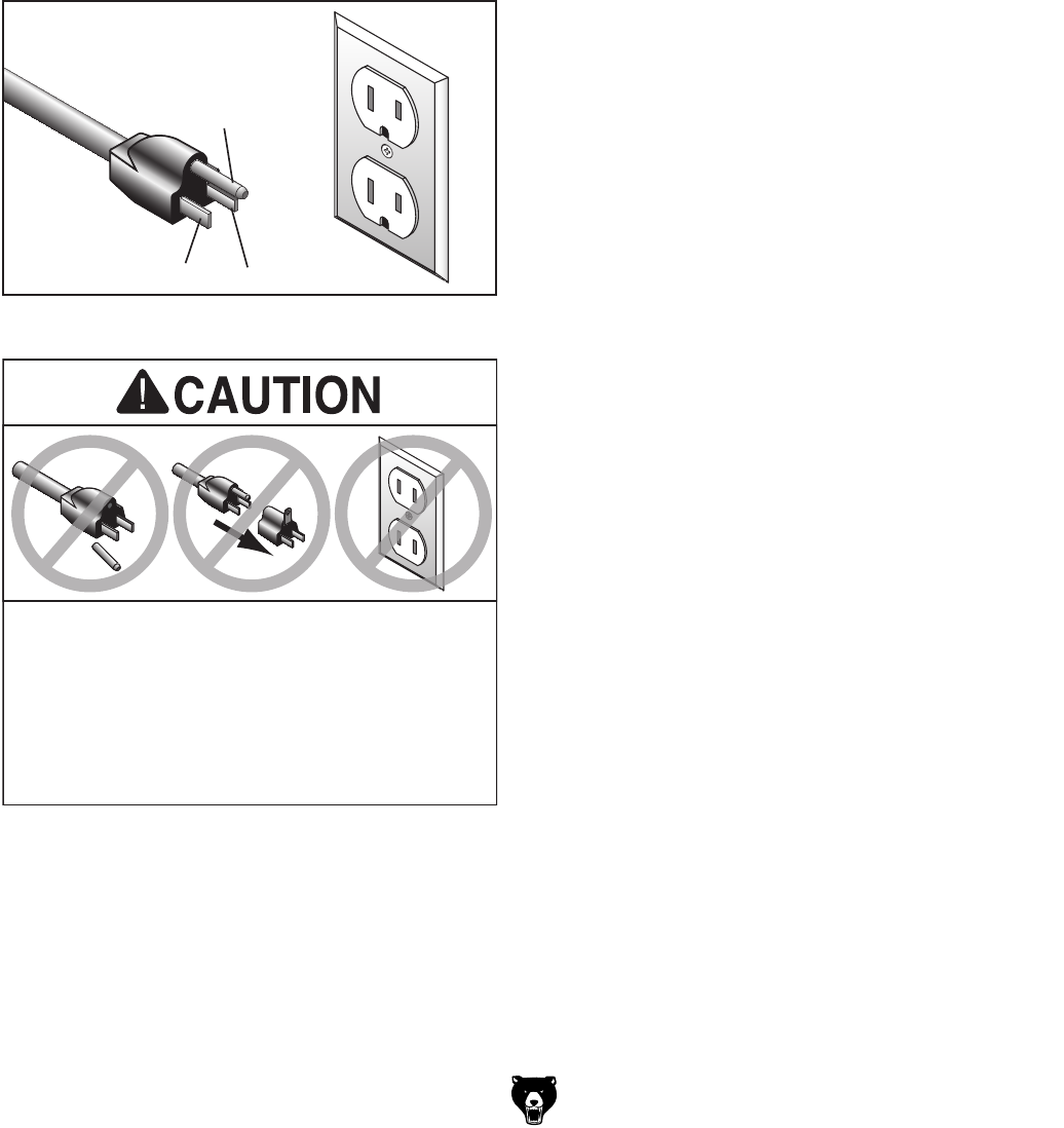
Figure 6. Typical 5-15 plug and receptacle.
Grounding Prong
Neutral Hot
5-15 PLUG
GROUNDED
5-15 RECEPTACLE
SHOCK HAZARD!
Two-prong outlets do not meet the grounding
requirements for this machine. Do not modify
or use an adapter on the plug provided—if
it will not fit the outlet, have a qualified
electrician install the proper outlet with a
verified ground.
This machine MUST be grounded. In the event
of certain malfunctions or breakdowns, grounding
reduces the risk of electric shock by providing a
path of least resistance for electric current.
This machine is equipped with a power cord that
has an equipment-grounding wire and a grounding
plug. Only insert plug into a matching receptacle
(outlet) that is properly installed and grounded in
accordance with all local codes and ordinances.
DO NOT modify the provided plug!
Minimum Gauge Size ...........................14 AWG
Maximum Length (Shorter is Better).......50 ft.
Model T25920/T25926 (Mfd. Since 08/14) -13-
SECTION 3: SETUP
Your machine was carefully packaged for safe
transportation. Remove the packaging materials
from around your machine and inspect it. If you
discover any damage, please call us immediately
at (570) 546-9663
for advice.
Save the containers and all packing materials for
possible inspection by the carrier or its agent.
Otherwise, filing a freight claim can be difficult.
When you are completely satisfied with the condi-
tion of your shipment, inventory the contents.
Unpacking
SUFFOCATION HAZARD!
Keep children and pets away
from plastic bags or packing
materials shipped with this
machine. Discard immediately.
The following are needed to complete the setup
process, but are not included with your machine.
Description Qty
• Additional People ....................................... 1
• Safety Glasses ........................................... 1
• Cleaner/Degreaser ..................... As Needed
• Disposable Shop Rags ............... As Needed
• Phillips Head Screwdriver #2 ..................... 1
• Leather Gloves ........................................... 1
• Flathead Screwdriver .................................. 1
Needed for Setup
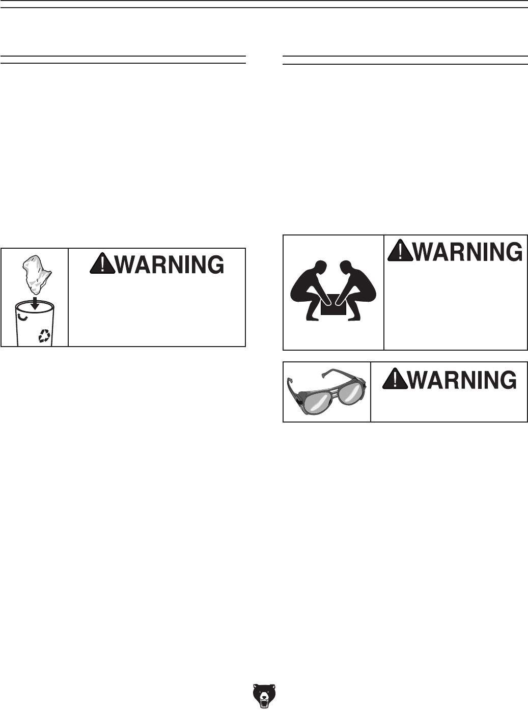
Wear safety glasses during
the entire setup process!
Model T25920/T25926 is
a heavy machine. DO
NOT over-exert yourself
while unpacking or mov-
ing your machine—get
assistance.
-14- Model T25920/T25926 (Mfd. Since 08/14)
NOTICE
If you cannot find an item on this list, care-
fully check around/inside the machine and
packaging materials. Often, these items get
lost in packaging materials while unpack-
ing or they are pre-installed at the factory.
Inventory
The following is a list of items shipped with your
machine. Before beginning setup, lay these items
out and inventory them.
If any non-proprietary parts are missing (e.g. a
nut or a washer), we will gladly replace them; or
for the sake of expediency, replacements can be
obtained at your local hardware store.
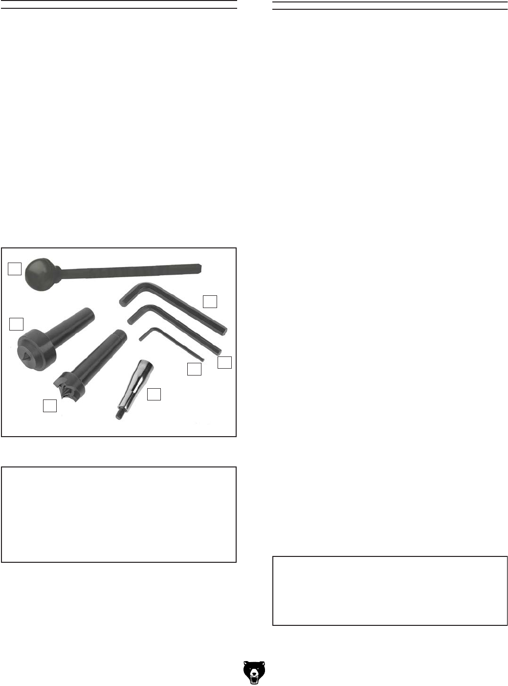
Box 1 (Figure 3) Qty
A. Knockout Rod ............................................. 1
B. Hex Wrench 8mm ....................................... 1
C. Hex Wrench 6mm ....................................... 1
D. Hex Wrench 3mm ....................................... 1
E. Handwheel Handle ..................................... 1
F. Spur Center ................................................ 1
G. Live Center ................................................. 1
Cleanup
The unpainted surfaces of your machine are
coated with a heavy-duty rust preventative that
prevents corrosion during shipment and storage.
This rust preventative works extremely well, but it
will take a little time to clean.
Be patient and do a thorough job cleaning your
machine. The time you spend doing this now will
give you a better appreciation for the proper care
of your machine's unpainted surfaces.
There are many ways to remove this rust preven-
tative, but the following steps work well in a wide
variety of situations. Always follow the manufac-
turer’s instructions with any cleaning product you
use and make sure you work in a well-ventilated
area to minimize exposure to toxic fumes.
Before cleaning, gather the following:
• Disposable rags
• Cleaner/degreaser (WD•40 works well)
• Safety glasses & disposable gloves
• Plastic paint scraper (optional)
Basic steps for removing rust preventative:
1.
Put on safety glasses.
2.
Coat the rust preventative with a liberal
amount of cleaner/degreaser, then let it soak
for 5–10 minutes.
3.
Wipe off the surfaces. If your cleaner/degreas-
er is effective, the rust preventative will wipe
off easily. If you have a plastic paint scraper,
scrape off as much as you can first, then wipe
off the rest with the rag.
4.
Repeat Steps 2–3 as necessary until clean,
then coat all unpainted surfaces with a quality
metal protectant to prevent rust.
NOTICE
Avoid chlorine-based solvents, such as
acetone or brake parts cleaner, that may
damage painted surfaces.
Figure 7. Inventory components.
B
DC
E
A
F
G
Model T25920/T25926 (Mfd. Since 08/14) -15-
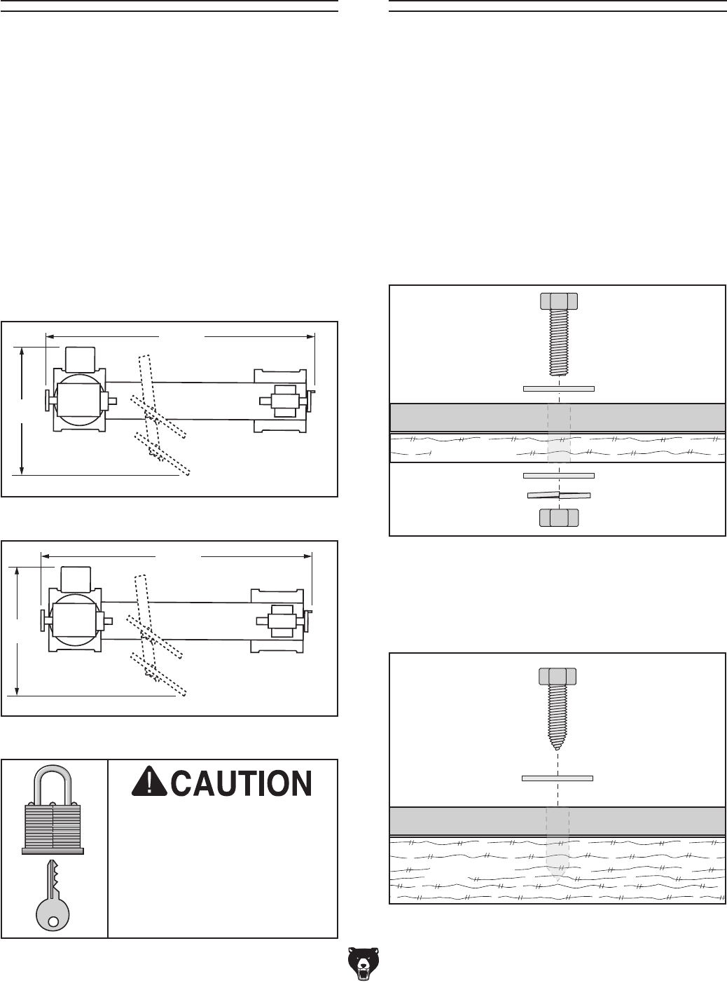
Site Considerations
Figure 8. T25920 minimum working clearances.
Figure 9. T25926 minimum working clearances.
Children and visitors may be
seriously injured if unsuper-
vised around this machine.
Lock entrances to the shop
or disable start switch or
power connection to prevent
unsupervised use.
Workbench Load
Refer to the Machine Data Sheet for the weight
and footprint specifications of your machine.
Some workbenches may require additional rein-
forcement to support the weight of the machine
and workpiece materials.
Consider anticipated workpiece sizes and addi-
tional space needed for auxiliary stands, work
tables, or other machinery when establishing a
location for this machine in the shop. Below is
the minimum amount of space needed for the
machine.
Placement Location
Figure 11. "Direct Mount" setup.
Machine Base
Workbench
Lag Screw
Flat Washer
Another option is a "Direct Mount" (see example
below) where the machine is secured directly to
the workbench with lag screws and washers.
Bench Mounting
The base of this machine has mounting holes
that allow it to be fastened to a workbench or
other mounting surface to prevent it from moving
during operation and causing accidental injury or
damage.
The strongest mounting option is a "Through
Mount" (see example below) where holes are
drilled all the way through the workbench—and
hex bolts, washers, and hex nuts are used to
secure the machine in place. The rubber feet
on the bottom of the base must be removed to
"Through Mount" the lathe.
Machine Base
Workbench
Hex
Bolt
Flat Washer
Flat Washer
Lock Washer
Hex Nut
38
3⁄4"
17
37
3⁄4"
173⁄4"
Figure 10. "Through Mount" setup.
-16- Model T25920/T25926 (Mfd. Since 08/14)
Assembly
Assembly consists of installing the electrical box
onto the base with two pre-installed Phillips head
screws, then installing the handwheel handle onto
the tailstock quill with the pre-installed flathead
screw.
To assemble machine:
1. Use (2) pre-installed Phillips head screws
and (2) flat washers to attach electrical box
to lathe, as shown in Figure 12.
2. Insert handwheel handle into quill handwheel
and tighten with flathead screwdriver.
3. To insert centers, refer to Installing/
Removing Headstock Center and Installing/
Removing Tailstock Center on Page 22.
Test Run
Once assembly is complete, test run the machine
to ensure it is properly connected to power and
safety components are functioning properly.
If you find an unusual problem during the test run,
immediately stop the machine, disconnect it from
power, and fix the problem BEFORE operating the
machine again. The
Troubleshooting
table in the
SERVICE section of this manual can help.
DO NOT start machine until all preceding
setup instructions have been performed.
Operating an improperly set up machine
may result in malfunction or unexpect-
ed results that can lead to serious injury,
death, or machine/property damage.
Serious injury or death can result from
using this machine BEFORE understanding
its controls and related safety information.
DO NOT operate, or allow others to operate,
machine until the information is understood.
To test run machine:
1. Clear all setup tools away from machine.
2. Connect machine to power supply.
3. Turn machine ON, verify motor operation,
and then turn machine OFF.
The motor should run smoothly and without
unusual problems or noises.
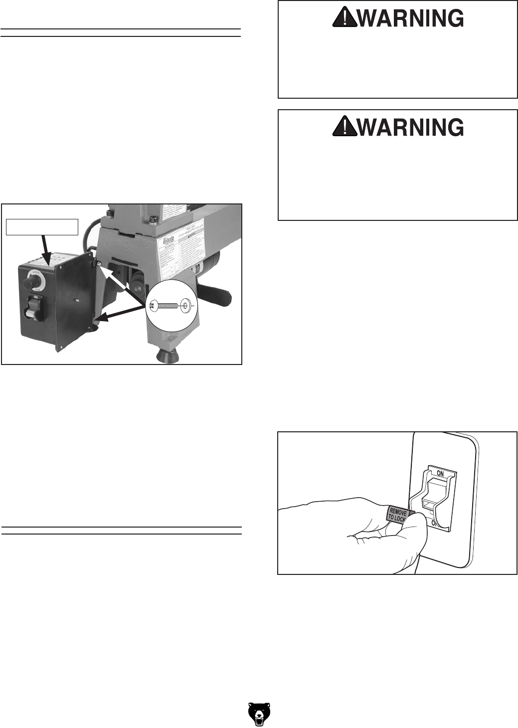
4. Remove key from toggle switch, as shown
below.
Figure 13. Removing key from toggle switch.
5. Try to start machine.
— Machine should NOT start. If it does start,
switch disabling feature is not functioning
properly and switch must be replaced.
Figure 12. Electrical box installed.
Electrical Box
x2
Model T25920/T25926 (Mfd. Since 08/14) -17-
SECTION 4: OPERATIONS
To complete a typical operation, the operator
does the following:
1. Examines workpiece to make sure it is suit-
able for turning. No extreme bows, knots, or
cracks should exist.
2. Prepares and trims workpiece to make it
roughly concentric.
3. Installs workpiece between centers, or attach-
es it to faceplate or chuck.
4. Adjusts tool rest to 1⁄8" above workpiece cen-
terline, and sets minimum clearance between
the workpiece and lip of tool rest to 1⁄4".
5. Rotates workpiece by hand to verify that the
spindle and workpiece rotate freely through-
out the range of motion.
6. Positions dust collection hood near work
piece to collect wood chips secure in place.
7. Ties back loose hair and clothing, and puts
on face shield and respirator. Takes all other
required safety precautions.
8. Starts lathe, adjusts lathe speed, and care-
fully begins turning operation, keeping chisel
against tool rest entire time it is cutting.
The purpose of this overview is to provide the nov-
ice machine operator with a basic understanding
of how the machine is used during operation, so
the
machine controls/components
discussed later
in this manual
are easier to understand.
Due to the generic nature of this overview, it is
not intended to be an instructional guide. To learn
more about specific operations, read this entire
manual and
seek additional training from expe-
rienced
machine operators, and do additional
research outside of this manual by reading "how-
to" books, trade magazines, or websites.
If you are not experienced with this type
of machine, WE STRONGLY RECOMMEND
that you seek additional training outside of
this manual. Read books/magazines or get
formal training before beginning any proj-
ects. Regardless of the content in this sec-
tion, Grizzly Industrial will not be held liable
for accidents caused by lack of training.
Keep hair, clothing, and
jewelry away from mov-
ing parts at all times.
Entanglement can result
in death, amputation, or
severe crushing injuries!
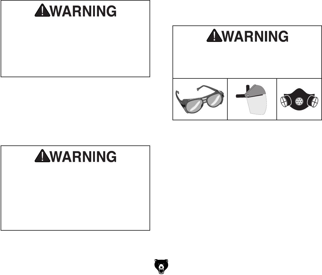
Eye injuries or respiratory problems can
occur while operating this tool. Wear per-
sonal protective equipment to reduce your
risk from these hazards.

-18- Model T25920/T25926 (Mfd. Since 08/14)
Stock Inspection &
Requirements
Some workpieces are not safe to turn or may
require modification before they are safe to
turn. Before turning a workpiece, inspect all
workpieces for the following:
• Workpiece Type:
This machine is intended for cutting natural
and man-made wood products, and some
plastics. Never attempt to cut any metal,
stone, or rubber workpiece; cutting these
materials can lead to machine damage or
severe injury.
• Foreign Objects:
Nails, staples, dirt, rocks and other foreign
objects are often embedded in wood. While
cutting, these objects can become dislodged
and hit the operator, cause tool grab, or break
the turning tool, which might then fly apart.
Always visually inspect your workpiece for
these items. If they can't be removed, DO
NOT turn the workpiece.
• Large/Loose Knots:
Loose knots can become dislodged during
the turning operation. Large knots can cause
a workpiece to completely break in half dur-
ing turning and cause machine damage and
personal injury. Choose workpieces that do
not have large/loose knots.
• Wet or "Green" Stock:
Cutting wood with a moisture content over
20% causes unnecessary wear on tooling
blades, increases the risk of tool grab, and
yields poor results.
• Excessive Warping:
Workpieces with excessive bowing or twist-
ing are unstable and unbalanced. Never turn
these workpieces at high speed, or instability
will be magnified and the workpiece can be
ejected from the lathe causing impact injures.
Only turn concentric workpieces!
Model T25920/T25926 (Mfd. Since 08/14) -19-
Adjusting Spindle
Speeds
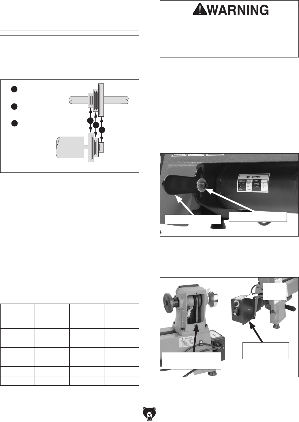
A
B
C
= High Range
1600–3800 RPM
= Mid Range
1250–2800 RPM
= Low Range
650–1450 RPM
ABC
Spindle
Motor
(Viewed from Back of Headstock)
Figure 14. Speed ranges for each belt position.
Your lathe has three speed ranges for maximum
turning options. These ranges are selected by
changing belt positions on the motor and spindle
pulleys (see Figure 14).
High range (A) is best when turning a workpiece
where a clean finish is required and only light
cuts are made. Mid range (B) is a compromise
between the high and low ranges. Low range
(C), which has more torque, is best when turn-
ing a workpiece where a lot of material must be
removed and a rough finish does not matter. Use
the speed dial to adjust the spindle speed within
each range.
Refer to the speed recommendations chart in
Figure 15 to choose the appropriate RPM for your
operation. Then choose the speed range that will
include the selected RPM.
Always choose correct spindle speed for
your operation. Using wrong speed may lead
to workpiece breaking loose or being thrown
from lathe at a high rate of speed, causing
fatal or severe impact injuries.
To change speeds:
1. DISCONNECT MACHINE FROM POWER!
2. Loosen belt tension screw (see Figure 16).
Be sure belt tension lever moves freely to
release tension from belt.
3. Open side access cover and remove rear
access cover (see Figure 17).
Figure 17. Side and rear access covers.
Speed
Chart
Rear Access Cover
Removed
Side Access
Cover Opened
Figure 16. Belt tension lever.
Belt Tension Lever Belt Tension Screw
Tool Needed:
Hex Wrench 6mm .............................................. 1
Diameter
of Work-
piece
Roughing
RPM
General
Cutting
RPM
Finishing
RPM
Under 2" 1520 3000 3000
2–4" 760 1600 2480
4–6" 510 1080 1650
6–8" 380 810 1240
8–10" 300 650 1000
10–12" 255 540 830
Figure 15. Speed recommendations.
-20- Model T25920/T25926 (Mfd. Since 08/14)
The tailstock is equipped with a cam-action
clamping system to secure it to the lathe bed.
When the lock lever is engaged, a plate lifts and
secures the tailstock to the bed.
Tool Needed:
Wrench 12mm ................................................... 1
To position tailstock along bed:
1. Disengage lock lever and move tailstock to
desired position (see Figure 20).
Adjusting Tailstock
2. Re-engage lock lever.
— If lock lever will not lock or unlock, then
adjust tailstock base mounting nut (locat-
ed on underside of tailstock base) in small
increments to achieve proper clamping
pressure (see Figure 21).
Figure 21. Mounting nut location.
Tailstock Mounting Nut
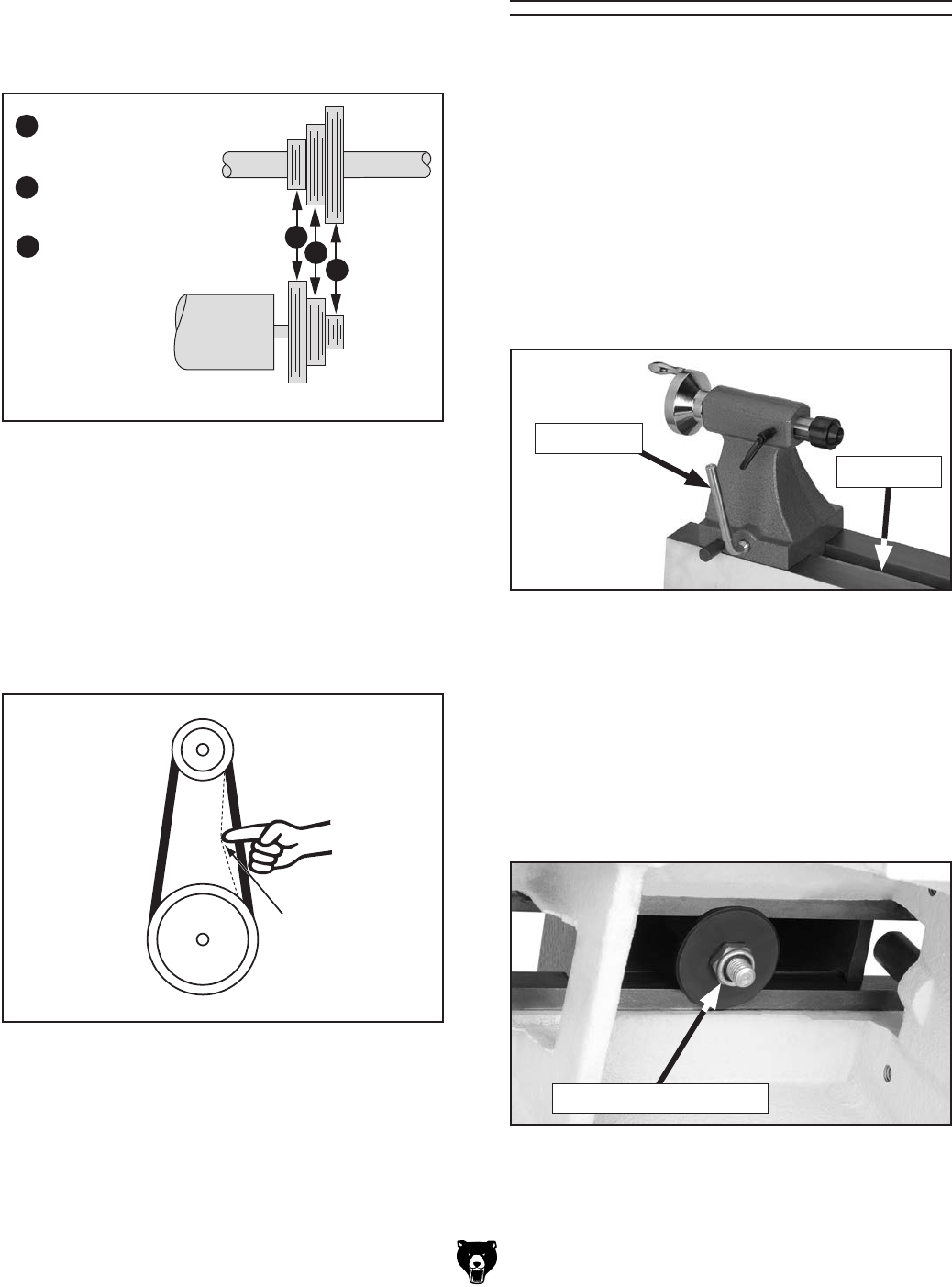
5. Move belt tension lever down to tension belt,
then tighten belt tension lever screw.
Note: When properly tensioned, the belt
should deflect about 1⁄2" when moderate
pressure is applied to the belt mid-way
between upper and lower pulleys, as shown in
Figure 19.
6. After verifying belt tension is correct, re-install
rear cover and close side access cover.
Pulley
Deflection
Pulley
Figure 19. Checking belt deflection.
4. Locate desired speed on speed chart on
top of control box (see Figure 15 on Page
19) and move belt to necessary grooves
on motor and spindle pulleys, as shown in
Figure 18.
1⁄2"
A
B
C
= High Range
1600–3800 RPM
= Mid Range
1250–2800 RPM
= Low Range
650–1450 RPM
ABC
Spindle
Motor
(Viewed from Back of Headstock)
Figure 18. Speed ranges for each belt position.
Figure 20. Typical tailstock lock lever to adjust
tailstock position.
Lathe Bed
Lock Lever
Model T25920/T25926 (Mfd. Since 08/14) -21-
The tool rest base is equipped with a cam-action
clamping system to secure it to the lathe bed.
When the lever is engaged, a locking plate lifts up
and secures the tool rest base to the bed.
Positioning Along Bed
1. Disengage base lock lever and slide tool rest
base along bed (see Figure 22).
Adjusting Tool Rest
2. Re-engage the tool rest base lock lever to
secure the tool rest assembly in position.
Note: The large clamping hex nut under-
neath the tool rest base will require occa-
sional adjusting to ensure proper clamping
pressure of the tool rest assembly to the bed.
Turn this hex nut in small increments to fine
tune the clamping pressure as needed.
Figure 22. Typical tool rest controls to adjust
position and height.
Tool Rest
Lock Lever
Tool Rest
Base
Lathe
Bed
Base Lock
Lever
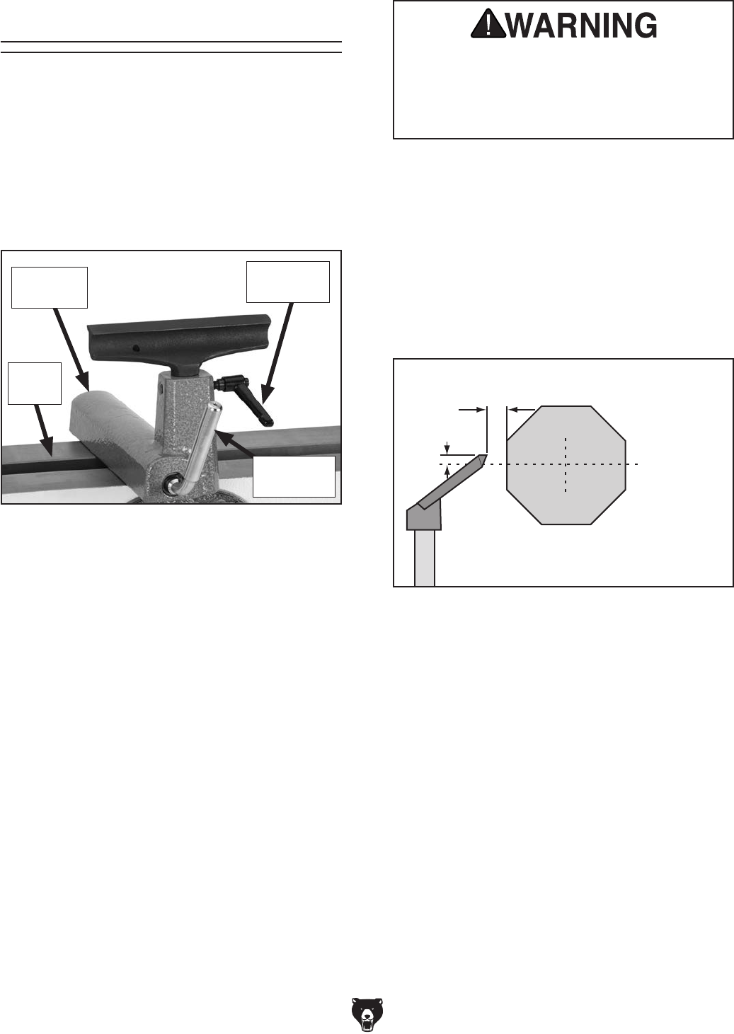
Adjusting Angle or Height
1. Loosen the tool rest base lock lever and the
tool rest lock lever to adjust the position of the
tool rest.
2. Position the tool rest approximately 1⁄4" away
from the workpiece and approximately 1⁄8"
above the workpiece center line, as shown in
Figure 23.
3. Re-tighten the tool rest lock lever and the tool
rest base lock lever to secure the tool rest in
position.
Workpiece
Center Line
Distances
Tool Rest
1⁄8"
1⁄4"
Figure 23. Tool rest position relative to
workpiece.
Always operate the lathe with the tool
rest assembly firmly locked in position.
Otherwise, serious personal injury may
occur by the tool being pulled from the
operator's hands.
-22- Model T25920/T25926 (Mfd. Since 08/14)
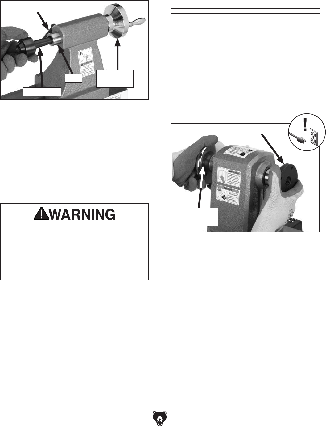
Figure 25. Typical spur center removal from
headstock spindle.
Knockout Rod
Installing/Removing
Tailstock Center
The included live center installs into the tailstock
with an MT#2 tapered fit.
Installing Live Center in Tailstock
1. Loosen quill lock handle (if locked) approxi-
mately half a turn.
2. Rotate quill handwheel clockwise until quill
protrudes about 3⁄4".
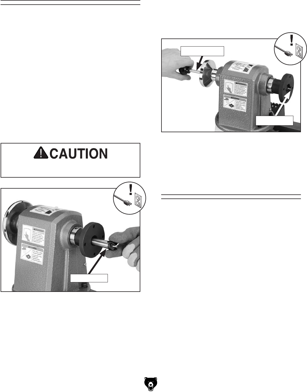
Removing Headstock Center
1. DISCONNECT MACHINE FROM POWER!
2. Insert knockout rod into outboard end of
spindle. Use a shop rag or wear a glove to
catch center and gently tap rod handle until
spur center is freed from spindle (see Figure
25).
Installing/Removing
Headstock Center
The spur center installs in the headstock spindle
with an MT#2 taper fit.
Tools Needed:
Gloves ............................................................... 1
Knockout Rod .................................................... 1
Figure 24. Typical installation of spur center into
headstock.
Spur Center
Spur center is sharp and may cause cuts.
Wear gloves when installing spur center.
4. Check that center is securely installed by giv-
ing it a quick tug. (A properly installed center
will not pull out by hand.)
Installing Headstock Center
1. DISCONNECT MACHINE FROM POWER!
2. Make sure surface of center and spindle are
free of debris and oily substances before
inserting center.
3. Insert tapered end of center into spindle, and
push it in quickly and firmly (see Figure 24).
Spur Center
Model T25920/T25926 (Mfd. Since 08/14) -23-
Removing Live Center from Tailstock
1. Loosen quill lock handle (if locked) approxi-
mately half a turn.
2. Turn quill handwheel counterclockwise until
tailstock quill fully retracts, causing live center
to be forced out of quill.
4. Tighten quill lock handle.
Quill
Live Center
Figure 26. Typical live center installation.
Quill Lock Lever
Quill
Handwheel
3. Insert live center, as shown in Figure 26,
and push firmly. Removing/Installing
Faceplate
These instructions cover removing and installing
the faceplate. To mount a workpiece to your face-
plate, refer to Faceplate Turning on Page 27.
Removing Faceplate
1. DISCONNECT MACHINE FROM POWER!
2. Hold headstock handwheel securely while
turning faceplate counterclockwise until it is
removed. If the spur center is installed, it will
be removed during this process.
Installing Faceplate
1. DISCONNECT MACHINE FROM POWER!
2. Thread faceplate onto spindle shaft until
secure against shoulder on spindle shaft.
Figure 27. Typical faceplate removal.
Faceplate
Headstock
Handwheel
Tailstock quill must always be locked during
lathe operation. Workpiece can be thrown
from lathe if this step is not observed. Also,
tailstock quill should not protrude from
tailstock housing more than 2'' or quill will
not be supported enough. Failure to follow
warnings may result in personal injury.
-24- Model T25920/T25926 (Mfd. Since 08/14)
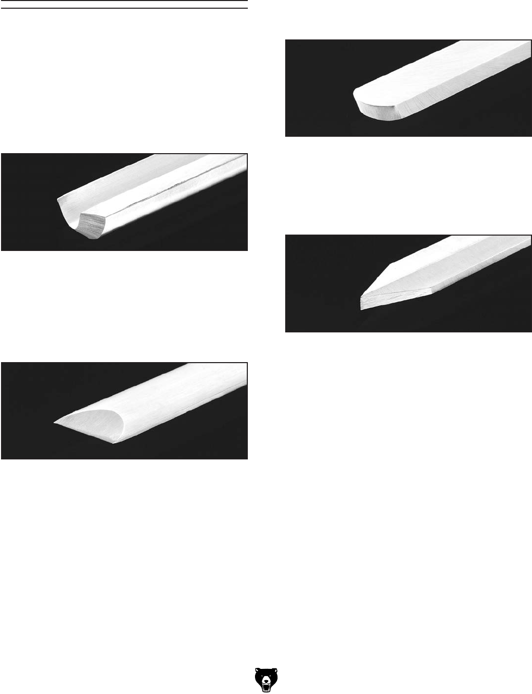
• Scrapers—Typically used where access for
other tools is limited, such as hollowing oper-
ations. This is a flat, double-ground tool that
comes in a variety of profiles (round nose,
spear point, square nose, etc.) to match
many different contours.
Figure 30. Example of a round nose scraper.
Figure 31. Example of a parting tool.
• Parting Tools—Used for sizing and cut-
ting off work. This is a flat tool with a sharp
pointed nose that may be single- or double-
ground.
• Specialty Tools—These are the unique,
special function tools to aid in hollowing, bowl
making, cutting profiles, etc. The Swan Neck
Hollowing Tool shown on Page 30 is a good
example of a specialty tool.
Selecting Turning
Tools
Lathe tools come in a variety of shapes and sizes
and usually fall into five major categories.
• Gouges—Mainly used for rough cutting,
detail cutting, and cove profiles. Rough gouge
is a hollow, double-ground tool with a round
nose, and detail gouge is a hollow, double-
ground tool with either a round or pointed
nose.
Figure 28. Example of a gouge.
• Skew Chisel—A very versatile tool that can
be used for planing, squaring, V-cutting,
beading, and parting off. The skew chisel is
flat, double-ground with one side higher than
the other (usually at an angle of 20-40˚).
Figure 29. Example of a skew chisel.
Model T25920/T25926 (Mfd. Since 08/14) -25-
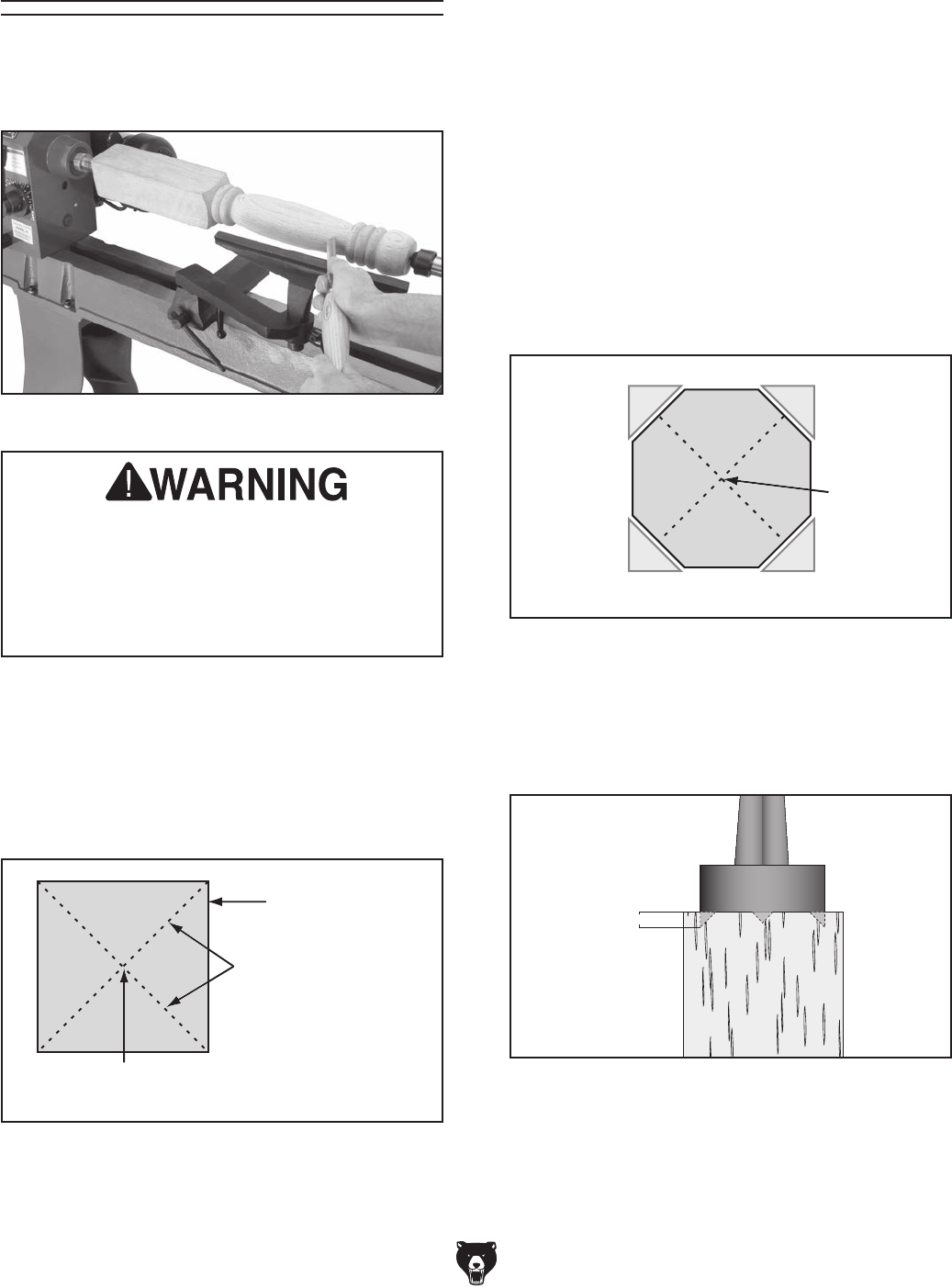
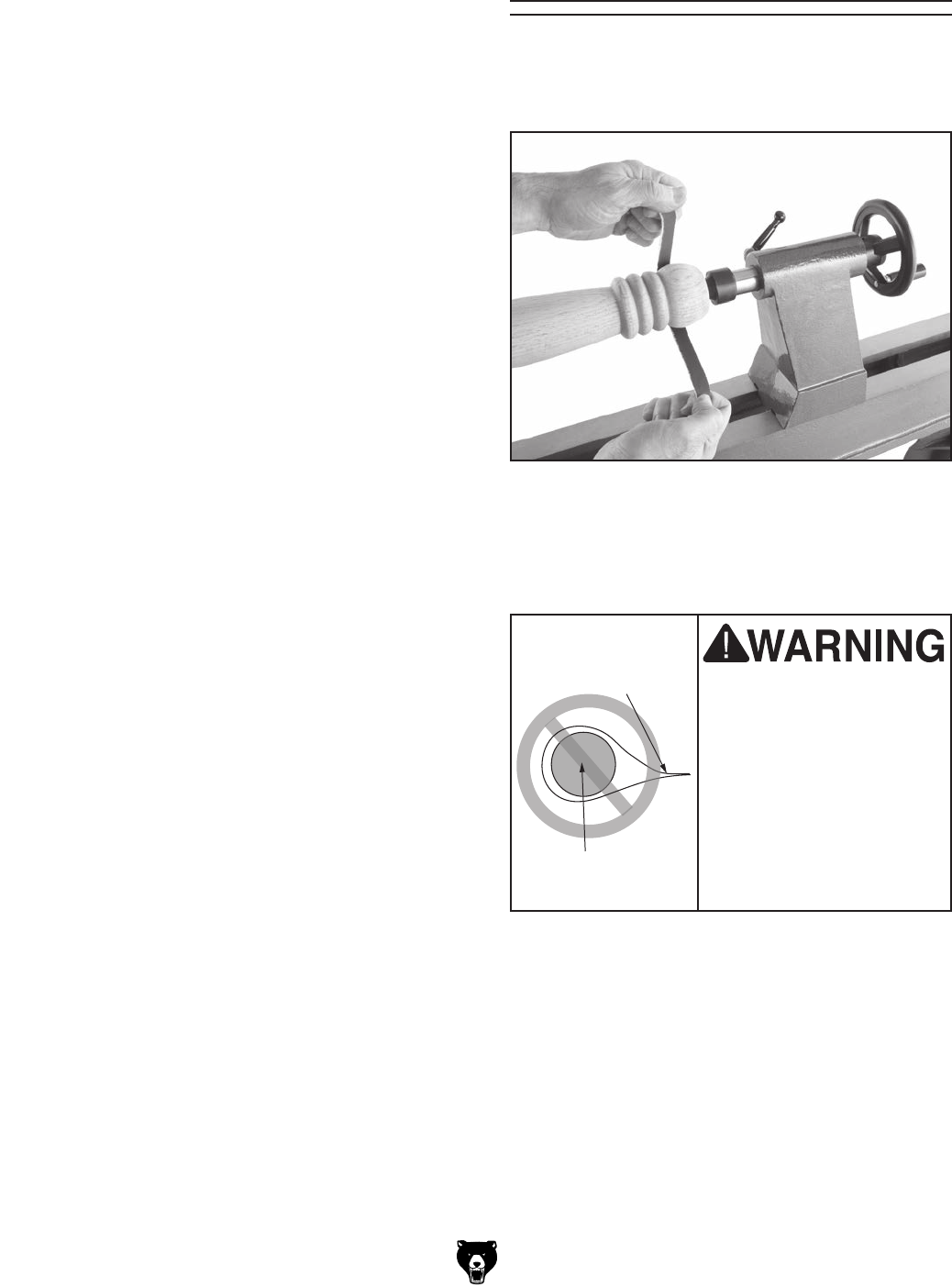
Spindle Turning
Spindle turning is the operation performed when
a workpiece is mounted between the headstock
and the tailstock, as shown in Figure 32.
Figure 32. Typical spindle turning operation.
To set up a spindle turning operation:
1. Find center point of both ends of your
workpiece by drawing diagonal lines from
corner to corner across end of workpiece, as
shown in Figure 33.
Figure 33. Workpiece marked diagonally from
corner to corner to determine the center.
Workpiece
Workpiece
Center
Pencil Lines
Marked Diagonally
Across Corners
2. Make center mark by using wood mallet and
tapping point of spur center into center of
workpiece on both ends.
3. Using 1⁄4" drill bit, drill 1⁄4" deep hole at center
mark on end of workpiece to be mounted on
headstock spur center.
4. To help embed spur center into workpiece,
cut 1⁄8" deep saw kerfs in headstock end of
workpiece along diagonal lines marked in
Step 1.
5. If your workpiece is over 2" x 2", cut corners
off workpiece lengthwise to make turning
safer and easier (see Figure 34).
6. Drive spur center into end center mark of
workpiece with wood mallet to embed it at
least 1⁄4" into workpiece, as shown in Figure
35.
¼"
Figure 35. Spur center properly embedded.
Workpiece
Center
Figure 34. Corners of workpiece removed.
Make sure the headstock and tailstock cen-
ters are properly aligned before beginning
any turning operation. Failure to observe
this warning could result in the workpiece
being thrown from the lathe, resulting in
serious personal injury.
-26- Model T25920/T25926 (Mfd. Since 08/14)
7. With workpiece still attached, insert spur cen-
ter into headstock spindle (refer to Installing/
Removing Headstock Center on Page 22
for additional instructions).
Note: Use the tool rest to support the oppo-
site end of workpiece so that the workpiece
and spur center do not separate during
installation.
8. Install live center into tailstock quill and
tighten quill lock lever to lock quill in position
(refer to Page 22 for additional instructions).
9. Slide tailstock toward workpiece until point of
live center touches workpiece center mark,
then lock tailstock in this position.
10. Loosen quill lock lever and rotate tailstock
handwheel to push live center into workpiece
at least a 1⁄4".
11. Properly adjust tool rest to the workpiece
(see Adjusting Tool Rest on Page 21).
12. Before beginning lathe operation, rotate
workpiece by hand to ensure that there is
safe clearance on all sides.
Keep lathe tool resting on tool rest ENTIRE
time that it is in contact with workpiece or
when preparing to make contact between
lathe tool and workpiece. Otherwise, spin-
ning workpiece could force lathe tool out
of your hands or entangle your hands with
workpiece. Failure to heed this warning
could result in serious personal injury.
Do not press workpiece too firmly with
tailstock or bearings will bind and over-
heat. Do not adjust tailstock too loosely or
workpiece will spin off lathe. Use good judg-
ment and care, otherwise, serious personal
injury could result from workpiece being
ejected at high speeds.
Spindle Turning Tips:
• When turning the lathe ON, stand away from
the path of the spinning workpiece until the
spindle reaches full speed and you can verify
that the workpiece will not come loose.
• Use the slowest speed when starting or stop-
ping the lathe.
• Select the right speed for the size of workpiece
that you are turning (refer to Figure 15 on
Page 19).
• Keep the turning tool on the tool rest the
ENTIRE time that it is in contact with the
workpiece.
• Learn the correct techniques for each tool
you will use. If you are unsure about how to
use the lathe tools, read books or magazines
about lathe techniques, and seek training
from experienced and knowledgeable lathe
users.
Eye injuries or respiratory problems can
occur while operating this tool. Wear per-
sonal protective equipment to reduce your
risk from these hazards.
Model T25920/T25926 (Mfd. Since 08/14) -27-
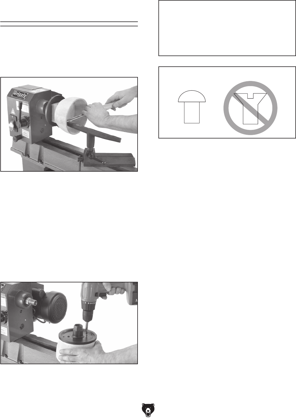
Faceplate Turning
Faceplate turning is when a workpiece is mounted
to the faceplate, which is then mounted to the
headstock spindle, as shown in Figure 36. This
type of turning is usually done with open-faced
workpieces like bowls or plates.
Figure 36. Typical faceplate turning operation.
Mounting Workpiece to Faceplate
1. Mark workpiece center in same manner as
described in Spindle Turning (see Page 25).
Note: Cut off corners of workpiece to make it
as close to "round" as possible, as described
in Spindle Turning on Page 25.
2. Center faceplate on workpiece and attach
with wood screws that do not have tapered
heads (see Figure 37).
3. Thread and secure faceplate onto head-
stock spindle (refer to Removing/Installing
Faceplate on Page 23 for faceplate mount-
ing instructions).
— If wood screws cannot be placed in the
workpiece, the faceplate can be mount-
ed to a backing block attached to the
workpiece (see Mounting Workpiece to
Backing Block on Page 28).
Correct Incorrect
Figure 38. Correct and incorrect screw types for
mounting workpiece to faceplate.
NOTICE
Only use screws with non-tapered heads
(see Figure 38) to attach the faceplate to
the workpiece. Screws with tapered heads
can split the faceplate or snap off during
operation.
Figure 37. Typical attachment of faceplate to
workpiece.
-28- Model T25920/T25926 (Mfd. Since 08/14)
Sanding/Finishing
After the turning operations are complete, the
workpiece can be sanded and finished before
removing it from the lathe, as shown in Figure 39.
Figure 39. Typical sanding operation.
Note: Whenever sanding or finishing, move the
tool rest holder out of the way to increase per-
sonal safety and gain adequate working room.
Wrapping sandpa-
per completely around
workpiece could pull
your hands into mov-
ing workpiece and may
cause serious injury.
Never wrap sandpa-
per or finishing materi-
als completely around
workpiece.
Sandpaper
Workpiece
1. Make backing block from a suitable size
piece of scrap wood.
Note: The faces of the backing block must be
flat and parallel to each other, or the uneven
surfaces will cause the workpiece to spin
eccentrically, causing unnecessary vibration
and runout. It is best to mount the backing
block to the faceplate and turn the other sur-
face flat prior to mounting.
2. Locate and mark center of workpiece and
backing block.
3. Drill a 1⁄4" hole through center of backing
block.
4. Look through hole in backing block to line up
center with workpiece, then glue and clamp
backing block to workpiece.
Note: Allow the glue to cure according to
manufacturer instructions.
5. Follow Steps 1–3 in Mounting Workpiece
to Faceplate (see Page 27) to attach back-
ing block to the faceplate.
Mounting Workpiece to Backing
Block
Model T25920/T25926 (Mfd. Since 08/14) -29-
SECTION 5: ACCESSORIES
H8049—6" 4-Jaw Wood Chuck 1
Independently adjustable jaws hold odd
shaped work. Jaws can be reversed for differ-
ent holding applications. Includes chuck wrench.
Figure 41. Model H8049 4-Jaw Wood Chuck.
Figure 42. Model H6542 Robert Sorby 8-PC Set.
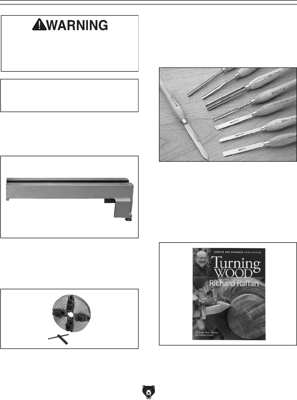
H6542—Robert Sorby HSS 8-PC Turning Set
This 8-pc. HSS Turning Tool Set includes 3⁄4"
Roughing Gouge, 1⁄4" and 1⁄2" Spindle Gouge, 3⁄8"
Bowl Gouge, 3⁄4" Standard Skew, 3⁄16" Diamond
Side Cut Scraper, 1" Square Scraper, and 1⁄2"
Round Scraper. Overall lengths are 16" to 19".
Installing unapproved accessories may
cause machine to malfunction, resulting in
serious personal injury or machine damage.
To reduce this risk, only install accessories
recommended for this machine by Grizzly.
NOTICE
Refer to our website or latest catalog for
additional recommended accessories.
order online at www.grizzly.com or call 1-800-523-4777
T27327—22" Bed Extension
Need a longer lathe but don't want to dedicate the
space to another machine, then add this 22" bed
extension and turn stock up to 38" long.
Figure 40. Model T27327 Bed Extension.
T25535—New Turning Wood Book
The appeal of woodturning is simple: with only
a few hand tools and a lathe, remarkable results
can be quickly achieved, including beautiful bowls,
boxes in the round, lamp bases, and furniture
parts. For over 20 years, woodturners have been
turning to Richard Raffan for expert advice and
inspiration.
Figure 43. T25535 Turning Wood Book.
-30- Model T25920/T25926 (Mfd. Since 08/14)
order online at www.grizzly.com or call 1-800-523-4777
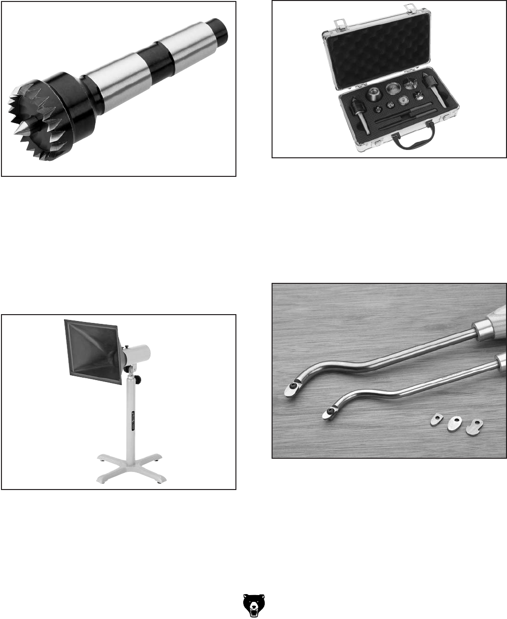
T10501—9 Piece Wood Lathe Center Kit
This all-in-one set features a variety of
interchangeable lathe centers for every spindle
turning application. Includes: MT#1 and MT#2
live centers, 3 spur centers, 3 multi-spur centers,
mounting adapter, wrenches and fitted case. Fits
lathes with 1" x 8 TPI RH spindles.
Figure 46. Lathe center kit with fitted case.
H5954—Robert Sorby Stebcentre MT#2, 1
1⁄4"
Razor sharp teeth bite into the workpiece for
secure operation and the spring loaded center
point controls the amount of drive or slip. This pat-
ented feature helps avoid the problem of ‘dig-in’.
Production turners can also load and unload their
work while the lathe is still running!
Figure 44. Model H5954 MT#2 Stebcentre.
T10117—Big Mouth Dust Hood with Stand
Capture dust from any machine operation with
this Big Mouth Dust Hood. Simply attach a 4" dust
collection hose and adjust the hood right where
you need it. The free-standing base eliminates
complicated machine set-ups and the tilting 16
3⁄8"
x 12
7⁄8" hood adjusts from 23" to 43" high. Every
shop needs one of these!
Figure 45. Dust collector with hood.
Figure 47. Swan neck hollowing tools.
H0507—20" Swan Neck Hollowing Tool
H0508—24" Swan Neck Hollowing Tool
An excellent choice for blind turning or undercut-
ting where reach is restricted. H0507 is designed
for end grain use while H0508 (with a more sub-
stantial steel cross section) is designed for both
end grain and side grain (bowl) use.
Model T25920/T25926 (Mfd. Since 08/14) -31-
SECTION 6: MAINTENANCE
Schedule
Lubricate locations shown in Figure 48 with light
machine oil or G96® Gun Treatment.
Lubrication
Figure 48. Lubrication locations.
Cleaning the Model T25920/T25926 is relatively
easy. Vacuum excess wood chips and sawdust,
and wipe off the remaining dust with a dry cloth.
If any resin has built up, use a resin dissolving
cleaner to remove it.
Protect the unpainted cast iron lathe bed by wip-
ing it clean with a lightly oiled rag after every
use—this ensures moisture from wood dust does
not remain on bare metal surfaces. Keep the bed
rust-free with regular applications of products like
G96® Gun Treatment, SLIPIT®, or Boeshield® T-9.
Cleaning &
Protecting
To reduce risk of shock or
accidental startup, always
disconnect machine from
power before adjustments,
maintenance, or service.
For optimum performance from your machine,
follow this maintenance schedule and refer to any
specific instructions given in this section.
Ongoing:
• Loose faceplate or mounting bolts.
• Damaged center or tooling.
• Worn or damaged wires.
• Loose machine components.
• Any other unsafe condition.
Daily:
• Clean off dust buildup.
• Clean and lubricate lathe bed, spindle, and
quill.
Monthly:
• Belt tension, damage, or wear.
Lubrication Point
Lubrication
Points

-32- Model T25920/T25926 (Mfd. Since 08/14)
Review the troubleshooting and procedures in this section to fix or adjust your machine if a problem devel-
ops. If you need replacement parts or you are unsure of your repair skills, then feel free to call our Technical
Support at (570) 546-9663.
SECTION 7: SERVICE
Troubleshooting
Motor & Electrical
Symptom Possible Cause Possible Solution
Machine does not
start or a breaker
trips.
1. Switch disabling key removed.
2. Incorrect power supply voltage or circuit
size.
3. Blown fuse.
4. Power supply circuit breaker tripped or fuse
blown.
5. Wiring is open/has high resistance.
6. Potentiometer/variable-speed dial at fault.
7. ON/OFF switch at fault.
8. Motor brushes at fault.
9. Motor is at fault.
1. Install switch disabling key.
2. Ensure correct power supply voltage and circuit
size.
3. Replace fuse/ensure no shorts.
4. Ensure circuit is sized correctly and free of shorts.
Reset circuit breaker or replace fuse.
5. Check for broken wires or disconnected/corroded
connections, and repair/replace as necessary.
6. Test/replace.
7. Replace switch.
8. Replace motor brushes.
9. Test/repair/replace.
Machine stalls or is
underpowered.
1. Machine is undersized for task.
2. Workpiece material not suitable.
3. Feed rate/cutting speed too fast for task.
4. Belt slipping.
5. Motor connection is wired incorrectly.
6. Pulley slipping on shaft.
7. Plug/receptacle at fault.
8. Motor has overheated.
9. Potentiometer/variable-speed dial at fault.
10. Motor brushes at fault.
11. Pulley/sprocket slipping on shaft
12. Motor is at fault.
1. Use sharp lathe tools; reduce feed rate/depth of cut.
2. Only cut wood/ensure moisture is below 20%.
3. Decrease feed rate/cutting speed.
4. Replace bad belt and re-tension (see Page 34).
5. Correct motor wiring connections.
6. Replace loose pulley.
7. Test for good contacts/correct wiring.
8. Clean off motor, let cool, and reduce workload.
9. Test/replace.
10. Replace motor brushes.
11. Replace loose pulley/shaft.
12. Test/repair/replace.
Machine has
vibration or noisy
operation (without
workpiece installed).
1. Machine incorrectly mounted to workbench
or floor.
2. Motor or component is loose.
3. Belt worn or loose.
4. Motor mount loose/broken.
5. Pulley is loose.
6. Motor bearings are at fault.
7. Workpiece or chuck at fault.
1. Adjust feet, shim, or tighten mounting hardware.
2. Inspect/replace stripped or damaged bolts/nuts, and
re-tighten with thread locking fluid-4
3. Inspect/replace belts (see Page 34).
4. Tighten/replace.
5. Replace shaft, pulley, setscrew, and key as
required.
6. Test by rotating shaft; rotational grinding/loose shaft
requires bearing replacement.
7. Center workpiece in chuck/faceplate; reduce RPM;
replace defective chuck.

Model T25920/T25926 (Mfd. Since 08/14) -33-
Symptom Possible Cause Corrective Action
Vibration noise while
machine is running; noise
changes when speed is
changed.
1. Belt cover loose. 1. Tighten the knobs that secure the belt cover; if nec-
essary install a soft, vibration dampening material
between the belt cover and the headstock casting.
Excessive vibration (with
workpiece installed).
1. Workpiece mounted incorrectly.
2. Headstock, tailstock, or tool rest not
securely clamped to lathe bed.
3. Workpiece warped, out of round, or
is flawed.
4. Spindle speed is set too fast for
mounted workpiece.
5. Lathe is resting on an uneven sur-
face.
6. Motor mount bolts are loose.
7. Belt is worn or damaged.
8. Spindle bearings are worn.
1. Re-mount workpiece, making sure that centers are
embedded in true center of workpiece.
2. Check clamp levers and tighten if necessary.
3. Cut workpiece to correct, or use a different
workpiece.
4. Reduce the spindle speed.
5. Shim base or adjust feet on workbench to remove
any wobbles.
6. Tighten motor mount bolts.
7. Replace belt (see Page 34).
8. Replace spindle bearings.
Chisels grab or dig into
workpiece.
1. Tool rest set too low.
2. Tool rest set too far from workpiece.
3. Wrong chisel/tool being used.
4. Chisel/tool dull.
1. Set tool rest higher. See Page 21 for how to prop-
erly set tool rest height.
2. Move the tool rest closer to the workpiece. See
Page 21 for the proper workpiece/tool rest clear-
ance.
3. Use the correct chisel/tool; educate yourself by
reading books, trade magazines, or seeking help
from an experienced lathe operator.
4. Sharpen or replace the chisel/tool you are using.
Bad surface finish on
workpiece.
1. Wrong spindle speed.
2. Dull chisel or wrong chisel being
used for the operation.
1. Use trial-and-error to find a better spindle speed.
2. Sharpen chisel or try a different chisel.
Tailstock moves under
load.
1. Tailstock mounting bolt loose.
2. Bed surface is oily or greasy.
1. Tighten.
2. Clean bed surface to remove excess oil/grease.
Can't remove tapered tool
from tailstock barrel.
1. Tailstock barrel not retracted all the
way back into the tailstock.
2. Debris was not removed from taper
before inserting into barrel.
1. Turn the barrel handwheel until it forces taper out of
barrel.
2. Always make sure that taper surfaces are clean.
Wood Lathe Operation
-34- Model T25920/T25926 (Mfd. Since 08/14)
Tensioning &
Replacing Belt
Tools Needed:
Hex Wrenches 3mm, 6mm ...........................1 Ea
Rubber/Wood Mallet .......................................... 1
The drive belt stretches as the lathe is used.
Most of the stretching will occur during the first
16 hours, but may continue with further use. If the
lathe loses power while making a cut, the belt may
be slipping and need tensioning. If the belt shows
signs of excessive wear, or damage, replace it.
Figure 49. Belt tension controls.
Belt Tension Lever Belt Tension Screw
Tensioning Belt
1. DISCONNECT MACHINE FROM POWER!
2. Remove rear access cover and loosen belt
tension screw (see Figure 49).
3. Press belt tension lever down, then tighten
belt tension screw.
4. Press belt with moderate pressure in center
to check tension. Belt is correctly tensioned
when there is approximately 1⁄2" deflection
when pushed as shown in Figure 50.
— If there is more than 1⁄2" deflection repeat
the tensioning procedure until it is correct.
If tension cannot be achieved replace belt.
Pulley Deflection
Pulley
Figure 50. Checking belt deflection.
1⁄2"
Replacing Belt
1. DISCONNECT MACHINE FROM POWER!
2. Remove rear access cover and open side
access cover.
3. Release belt tension, then remove belt from
motor pulley.
4. Loosen set screws on spindle handwheel (see
Figure 51), and turn clockwise to unthread
and remove.
Figure 51. Set screw locations.
Spindle
Handwheel
Set Screw
Spindle Pulley
Set Screw
5. Re-install rear access cover.
5. Loosen spindle pulley set screw.
6. Tap spindle far enough out of headstock
so belt can be removed (see Figure 52 on
Page 35). A rubber or wooden mallet may be
required. Take care not to damage spindle
threads or lose parts. DO NOT remove spin-
dle pulley.
Model T25920/T25926 (Mfd. Since 08/14) -35-
Figure 52. Belt removal (pulley removed for
clarity).
7. Place new belt over spindle pulley.
8. Slide spindle back through headstock and into
original position. A mallet may be required to
reseat bearing.
9. Install headstock spindle handwheel and
tighten both set screws.
10. Loosely install belt on inner or outermost
motor pulley position.
11. Move belt tension lever down to tension belt
then tighten belt tension screw.
12. Follow Step 4 in the Tensioning Belt proce-
dure to set belt tension.
13. Re-install rear access cover and close side
access cover.
Replacing Fuse
This lathe features an on-board fuse designed
to protect sensitive electrical parts from ther-
mal damage in the event of an overload. If the
machine does not start check the fuse.
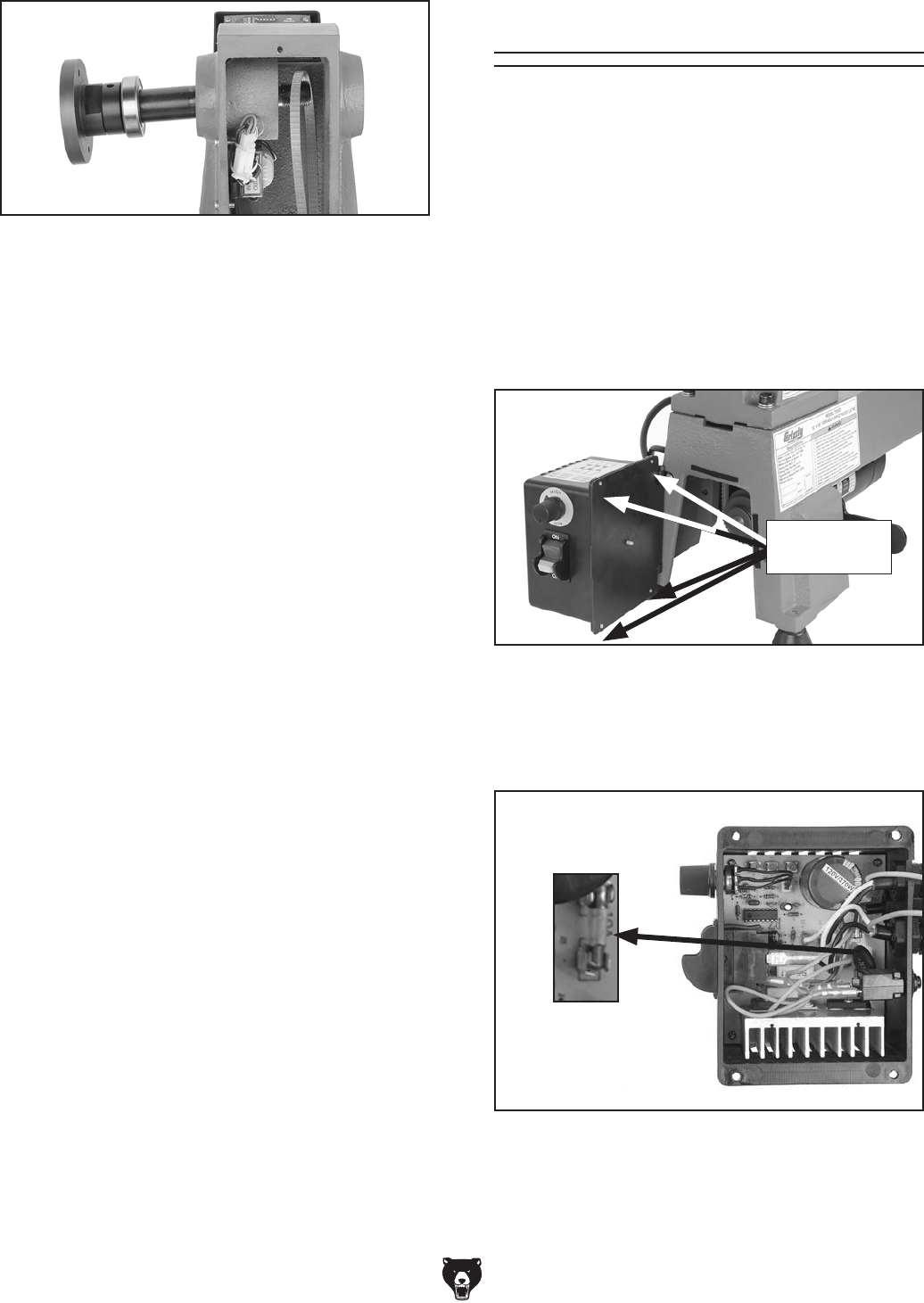
To replace fuse:
1. DISCONNECT MACHINE FROM POWER!
2. Remove (4) Phillips head screws holding
electrical box to side access cover (see
Figure 53).
Figure 54. 10A fuse location on circuit board.
3. Carefully remove fuse, then insert new fuse
shown in Figure 54.
Figure 53. Electrical box screw locations, (side
access door open for clarity).
4. Re-install electrical box onto side access
cover with screws removed in Step 2, then
test run.
Phillips Head
Screws
-36- Model T25920/T25926 (Mfd. Since 08/14)
Replacing Brushes
Your machine is equipped with a universal motor
that uses carbon brushes to transmit electri-
cal current inside the motor. These brushes
are considered to be regular "wear items" or
"consumables" that will eventually need to be
replaced. The frequency of this replacement is
directly related to how much the motor is used
and how hard it is pushed.
Replace the carbon brushes when the motor no lon-
ger reaches full power, or when the brushes mea-
sure less than 1⁄4" long (new brushes are 5⁄8" long).
Tools Needed Qty
Hex Wrench 6mm .............................................. 1
Flat Head Screwdriver #2 .................................. 1
T25920/T25926: Both models use same motor
replacement brushes (Part# PT25920084).
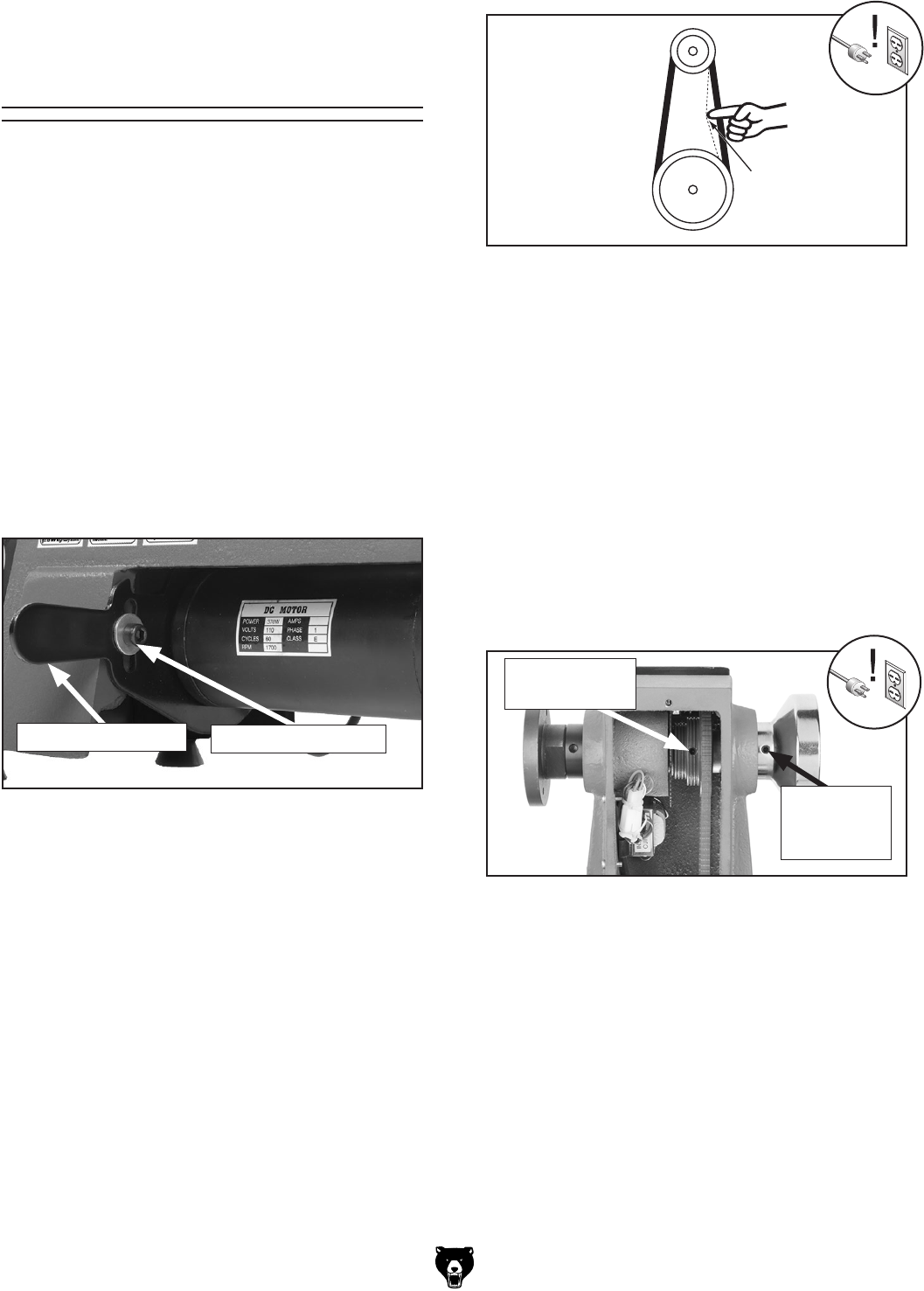
1. DISCONNECT MACHINE FROM POWER!
2. Loosen belt tension screw, raise motor to
gain access to lower brush cap, then tighten
belt tension screw.
3. Unscrew brush cap with flat head screwdriver
(see Figure 55).
Replacing Lathe Motor Brushes
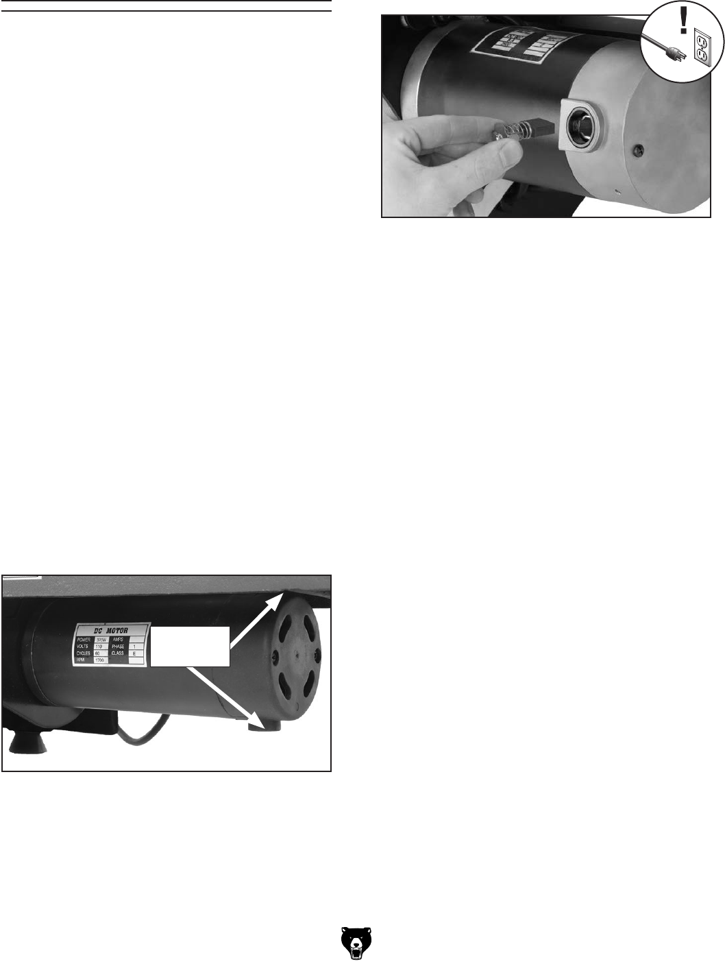
Figure 56. Removing brush from motor.
4. Carefully remove brush from motor (see
Figure 56).
Figure 55. Motor brush cap locations.
Brush Cap
Locations
5. Install new brush and re-install brush cap.
6. Repeat Steps 3–5 to replace brush on top-
side of motor.
7. Tension belt (refer to Tensioning &
Replacing Belt on Page 34 for details).
8. Re-install rear access cover, and close side
access cover.
9. Test run machine.

Model T25920/T25926 (Mfd. Since 08/14) -37-
SHOCK HAZARD. Working on wiring that is con-
nected to a power source is extremely dangerous.
Touching electrified parts will result in personal
injury including but not limited to severe burns,
electrocution, or death. Disconnect the power
from the machine before servicing electrical com-
ponents!
MODIFICATIONS. Modifying the wiring beyond
what is shown in the diagram may lead to unpre-
dictable results, including serious injury or fire.
This includes the installation of unapproved after-
market parts.
WIRE CONNECTIONS. All connections must
be tight to prevent wires from loosening during
machine operation. Double-check all wires dis-
connected or connected during any wiring task to
ensure tight connections.
CIRCUIT REQUIREMENTS. You MUST follow
the requirements at the beginning of this manual
when connecting your machine to a power source.
WIRE/COMPONENT DAMAGE. Damaged wires
or components increase the risk of serious per-
sonal injury, fire, or machine damage. If you notice
that any wires or components are damaged while
performing a wiring task, replace those wires or
components.
MOTOR WIRING. The motor wiring shown in
these diagrams is current at the time of printing
but may not match your machine. If you find this
to be the case, use the wiring diagram inside the
motor junction box.
CAPACITORS/INVERTERS. Some capacitors
and power inverters store an electrical charge for
up to 10 minutes after being disconnected from
the power source. To reduce the risk of being
shocked, wait at least this long before working on
capacitors.
EXPERIENCING DIFFICULTIES. If you are expe-
riencing difficulties understanding the information
included in this section, contact our Technical
Support at (570) 546-9663.
Wiring Safety Instructions
The photos and diagrams
included in this section are
best viewed in color. You
can view these pages in
color at www.grizzly.com.
These pages are current at the time of printing. However, in the spirit of improvement, we may make chang-
es to the electrical systems of future machines. Compare the manufacture date of your machine to the one
stated in this manual, and study this section carefully.
If there are differences between your machine and what is shown in this section, call Technical Support at
(570) 546-9663 for assistance BEFORE making any changes to the wiring on your machine. An updated
wiring diagram may be available. Note: Please gather the serial
number and manufacture date of your
machine before calling. This information can be found on the main machine label.
SECTION 8: WIRING
machine
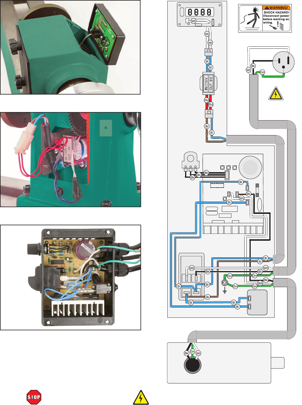
-38- Model T25920/T25926 (Mfd. Since 08/14)
READ ELECTRICAL SAFETY
ON PAGE 37!
110 VAC
5-15 Plug
Neutral
Hot
Ground
MOTOR 110V
10A
250VAC
A1218
AC1
AC2
M –
M+
NTC 2.5D-20
Toggle Switch
(viewed from behind)
DRO XBS2012.6.11
Ground
Spindle Control
Circuit Board
DZ-236A1
Potentiometer
B103
Circuit
Breaker
RU L2
6A
50VDC
RU CB-8
E19 4417
Transformer
Figure 58. Connections in headstock.
Figure 59. Electrical box.
Figure 57. Digital readout display board.
T25920/T25926 Wiring Diagram
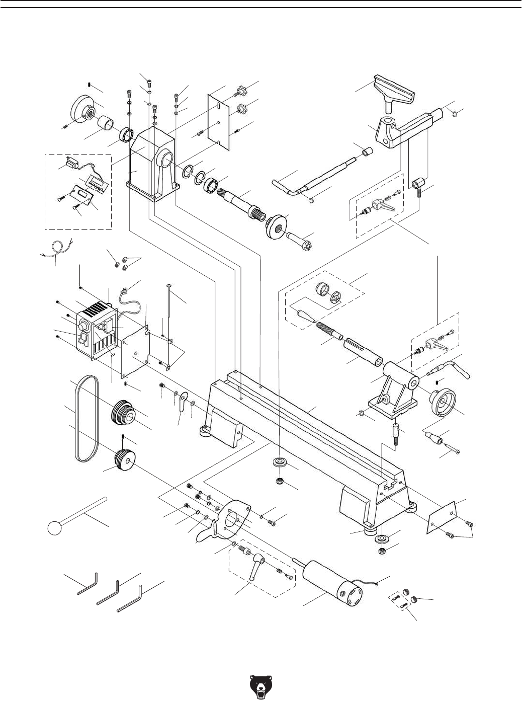
Model T25920/T25926 (Mfd. Since 08/14) -39-
1
2
2
2
2
34
4
5
6
78
9
10
11
12
13 13
14
15
16
17
18
18
19
20
21
22
23
27
30
31
32
33
34
35
36
37
38
39
40
41
41
42
43
47
48
49
50
51
52
53 5455
56 57
58
59
60 61
62
77
78
63
64
65
66
67
68
69
70
71 72
73
74
74
5
6
74
76
80
81
82
83
24 25 26
28
44
45
79
29
46
84
T25920 Breakdown
SECTION 9: PARTS
Please Note: We do our best to stock replacement parts whenever possible, but we cannot guarantee that all parts shown here
are available for purchase. Call (800) 523-4777 or visit our online parts store at www.grizzly.com to check for availability.

-40- Model T25920/T25926 (Mfd. Since 08/14)
REF PART # DESCRIPTION REF PART # DESCRIPTION
1 PT25920001 HANDWHEEL 82MM X M18-2.5 LH BORE 43 PT25920043 MOTOR PLATE HANDLE ASSEMBLY
2 PT25920002 SET SCREW M6-1 X 12 44 PT25920044 MOTOR CORD 18G 3W 16"
3 PT25920003 COLLAR SPINDLE 45 PT25920045 SWITCH CORD 18G 3W 22"
4 PT25920004 BALL BEARING 80105 46 PT25920046 MOTOR CARBON BRUSH CAP
5 PT25920005 CAP SCREW M8-1.25 X 25 47 PT25920047 CAP SCREW M8-1.25 X 12
6 PT25920006 LOCK WASHER 8MM 48 PT25920048 MOTOR MOUNT PLATE
7 PT25920007 REAR BELT ACCESS DOOR 49 PT25920049 FLAT WASHER 6MM
8 PT25920008 THUMB SCREW M5-.8 X 9 50 PT25920050 LOCK WASHER 6MM
9 PT25920009 STATIONARY KNOB M5-.8 51 PT25920051 MOTOR PULLEY
10 PT25920010 SHOULDER SCREW M5-.8 X 7, 2 52 PT25920052 DRIVE PULLEY
11 PT25920011 FLAT HD SCR M5-.8 X 10 53 PT25920053 POLY V-BELT 3V X 25L
12 PT25920012 HEADSTOCK 54 PT25920054 SWITCH BOX LATCH BOLT M4-.7 X 5
13 PT25920013 INT RETAINING RING 47MM 55 PT25920055 WAVY WASHER 6MM
14 PT25920014 HEADSTOCK SPINDLE 56 PT25920056 SWITCH BOX LATCH
15 PT25920015 FACEPLATE 3-1/4" 57 PT25920057 FLAT WASHER 4MM
16 PT25920016 SPUR CENTER MT#2 58 PT25920058 HINGE
17 PT25920017 TOOL REST LOCK HANDLE 59 PT25920059 PHLP HD SCR M4-.7 X 8
18 PT25920018 EXT RETAINING RING 10MM 60 PT25920060 SWITCH BOX PLATE
19 PT25920019 TOOLREST BUSHING 61 PT25920061 HINGE PIN
20 PT25920020 TOOLREST 150MM 62 PT25920062 POWER CORD 18G 3W 72" 5-15P
21 PT25920021 TOOLREST BASE 63 PT25920063 CIRCUIT BREAKER 6A GENERAL
22 PT25920022 TOOLREST CAM FOLLOWER 64 PT25920064 CIRCUIT BOARD
23 PT25920023 ADJUSTABLE HANDLE M8-1.25 X 20 65 PT25920065 PHLP HD SCR M4-.7 X 6
24 PT25920024 HEX WRENCH 3MM 66 PT25920066 SWITCH BOX
25 PT25920025 HEX WRENCH 6MM 67 PT25920067 POTENTIOMETER B103
26 PT25920026 HEX WRENCH 8MM 68 PT25920068 TOGGLE SWITCH RU CB-8 E19 4417
27 PT25920027 LIVE CENTER MT#2 69 PT25920069 SET SCREW M6-1 X 12
28 PT25920028 FENDER WASHER 8MM 70 PT25920070 MOTOR 550W 110VDC
29 PT25920029 MOTOR CARBON BRUSH 2-PC SET 71 PT25920071 RUBBER FOOT M8-1.25 X 15
30 PT25920030 TAILSTOCK LEADSCREW 72 PT25920072 LOCK NUT M8-1.25
31 PT25920031 TAILSTOCK QUILL 73 PT25920073 EXT RETAINING RING 10MM
32 PT25920032 TAILSTOCK 74 PT25920074 FLAT WASHER 8MM
33 PT25920033 TAILSTOCK LEVER 76 PT25920076 FLAT HD SCR M6-1 X 12
34 PT25920034 HANDWHEEL 83MM X 15MM BORE 77 PT25920077 STRAIN RELIEF 5/16" SNAP-IN ST
35 PT25920035 HANDWHEEL HANDLE 6MM X 50MM 78 PT25920078 STRAIN RELIEF 1/4" SNAP-IN ST
36 PT25920036 SHOULDER SCREW M6-1 X 53 79 PT25920079 FUSE 10A 250V FAST-ACTING GLASS
37 PT25920037 TAILSTOCK CLAMP BOLT M8-1.25 X 30 80 PT25920080 DIGITAL DISPLAY COVER
38 PT25920038 BED 81 PT25920081 DIGITAL DISPLAY PLATE
39 PT25920039 RETAINING PLATE 82 PT25920082 PHLP HD SCR M4-.7 X 16
40 PT25920040 CAP SCREW M10-1.5 X 12 83 PT25920083 TRANSFORMER 110V/9V
41 PT25920041 LOCK PLATE 84 PT25920084 KNOCKOUT BAR
42 PT25920042 LOCK NUT M10-1.5
T25920 Parts List
Safety labels help reduce the risk of serious injury caused by machine hazards. If any label comes
off or becomes unreadable, the owner of this machine MUST replace it in the original location
before resuming operations. For replacements, contact (800) 523-4777 or www.grizzly.com.
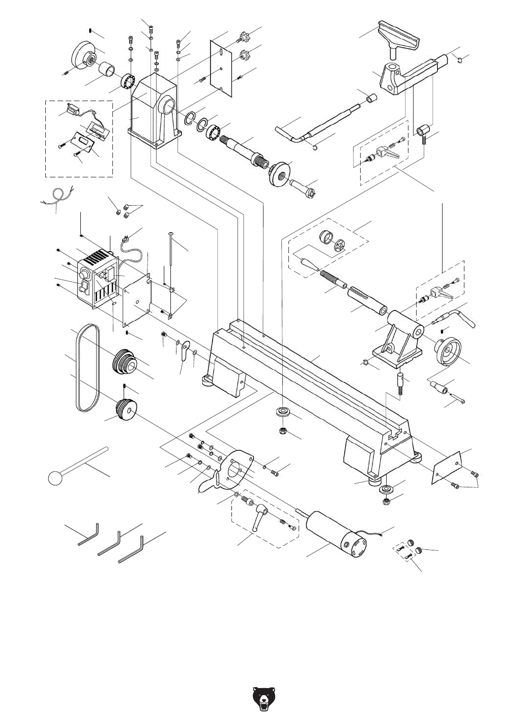
Model T25920/T25926 (Mfd. Since 08/14) -41-
Please Note: We do our best to stock replacement parts whenever possible, but we cannot guarantee that all parts shown here
are available for purchase. Call (800) 523-4777 or visit our online parts store at www.grizzly.com to check for availability.
1
2
2
2
2
34
4
5
6
78
9
10
11
12
13 13
14
15
16
17
18
18
19
20
21
22
23
27
30
31
32
33
34
35
36
37
38
39
40
41
41
42
43
47
48
49
50
51
52
53 5455
56 57
58
59
60 61
62
77
78
63
64
65
66
67
68
69
70
71 72
73
74
74
5
6
74
76
80
81
82
83
24 25 26
28
44
45
79
29
46
84
T25926 Breakdown

-42- Model T25920/T25926 (Mfd. Since 08/14)
T25926 Parts List
REF PART # DESCRIPTION REF PART # DESCRIPTION
1 PT25926001 HANDWHEEL 82MM X M18-2.5 LH BORE 43 PT25926043 MOTOR PLATE HANDLE ASSEMBLY
2 PT25926002 SET SCREW M6-1 X 12 44 PT25926044 MOTOR CORD 18G 3W 16"
3 PT25926003 COLLAR SPINDLE 45 PT25926045 SWITCH CORD 18G 3W 22"
4 PT25926004 BALL BEARING 80105 46 PT25926046 MOTOR CARBON BRUSH CAP
5 PT25926005 CAP SCREW M8-1.25 X 25 47 PT25926047 CAP SCREW M8-1.25 X 12
6 PT25926006 LOCK WASHER 8MM 48 PT25926048 MOTOR MOUNT PLATE
7 PT25926007 REAR BELT ACCESS DOOR 49 PT25926049 FLAT WASHER 6MM
8 PT25926008 THUMB SCREW M5-.8 X 9 50 PT25926050 LOCK WASHER 6MM
9 PT25926009 STATIONARY KNOB M5-.8 51 PT25926051 MOTOR PULLEY
10 PT25926010 SHOULDER SCREW M5-.8 X 7, 2 52 PT25926052 DRIVE PULLEY
11 PT25926011 FLAT HD SCR M5-.8 X 10 53 PT25926053 POLY V-BELT 3V X 25L
12 PT25926012 HEADSTOCK 54 PT25926054 SWITCH BOX LATCH BOLT M4-.7 X 5
13 PT25926013 INT RETAINING RING 47MM 55 PT25926055 WAVY WASHER 6MM
14 PT25926014 HEADSTOCK SPINDLE 56 PT25926056 SWITCH BOX LATCH
15 PT25926015 FACEPLATE 3-1/8" 57 PT25926057 FLAT WASHER 4MM
16 PT25926016 SPUR CENTER MT#2 58 PT25926058 HINGE
17 PT25926017 TOOL REST LOCK HANDLE 59 PT25926059 PHLP HD SCR M4-.7 X 8
18 PT25926018 EXT RETAINING RING 10MM 60 PT25926060 SWITCH BOX PLATE
19 PT25926019 TOOLREST BUSHING 61 PT25926061 HINGE PIN
20 PT25926020 TOOLREST 145MM 62 PT25926062 POWER CORD 18G 3W 72" 5-15P
21 PT25926021 TOOLREST BASE 63 PT25926063 CIRCUIT BREAKER 4A GENERAL
22 PT25926022 TOOLREST CAM FOLLOWER 64 PT25926064 CIRCUIT BOARD
23 PT25926023 ADJUSTABLE HANDLE M8-1.25 X 20 65 PT25926065 PHLP HD SCR M4-.7 X 6
24 PT25926024 HEX WRENCH 3MM 66 PT25926066 SWITCH BOX
25 PT25926025 HEX WRENCH 6MM 67 PT25926067 POTENTIOMETER B103
26 PT25926026 HEX WRENCH 8MM 68 PT25926068 TOGGLE SWITCH RU CB-8 E19 4417
27 PT25926027 LIVE CENTER MT#2 69 PT25926069 SET SCREW M6-1 X 12
28 PT25926028 FENDER WASHER 8MM 70 PT25926070 MOTOR 375W 110VDC
29 PT25926029 MOTOR CARBON BRUSH 2-PC SET 71 PT25926071 RUBBER FOOT M8-1.25 X 15
30 PT25926030 TAILSTOCK LEADSCREW 72 PT25926072 LOCK NUT M8-1.25
31 PT25926031 TAILSTOCK QUILL 73 PT25926073 EXT RETAINING RING 10MM
32 PT25926032 TAILSTOCK 74 PT25926074 FLAT WASHER 8MM
33 PT25926033 TAILSTOCK LEVER 76 PT25926076 FLAT HD SCR M6-1 X 12
34 PT25926034 HANDWHEEL 83MM X 15MM BORE 77 PT25926077 STRAIN RELIEF 5/16" SNAP-IN ST
35 PT25926035 HANDWHEEL HANDLE 6MM X 50MM 78 PT25926078 STRAIN RELIEF 1/4" SNAP-IN ST
36 PT25926036 SHOULDER SCREW M6-1 X 53 79 PT25926079 FUSE 10A 250V FAST-ACTING GLASS
37 PT25926037 TAILSTOCK CLAMP BOLT M8-1.25 X 30 80 PT25926080 DIGITAL DISPLAY COVER
38 PT25926038 BED 81 PT25926081 DIGITAL DISPLAY PLATE
39 PT25926039 RETAINING PLATE 82 PT25926082 PHLP HD SCR M4-.7 X 16
40 PT25926040 CAP SCREW M10-1.5 X 12 83 PT25926083 TRANSFORMER 110V/9V
41 PT25926041 LOCK PLATE 84 PT25926084 KNOCKOUT BAR
42 PT25926042 LOCK NUT M10-1.5
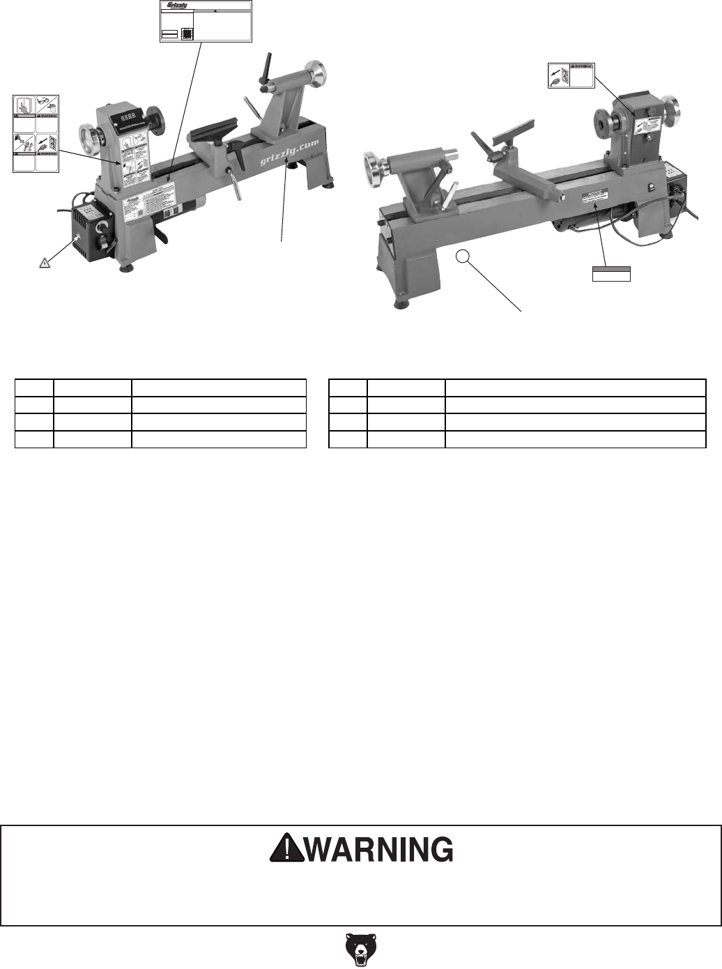
Model T25920/T25926 (Mfd. Since 08/14) -43-
Safety labels help reduce the risk of serious injury caused by machine hazards. If any label comes
off or becomes unreadable, the owner of this machine MUST replace it in the original location
before resuming operations. For replacements, contact (800) 523-4777 or www.grizzly.com.
T25920/T25926 Labels & Cosmetics
COPYRIGHT © GRIZZLY INDUSTRIAL, INC.
FOR GRIZZLY MACHINES ONLY! DO NOT REPRODUCE OR CHANGE THIS ARTWORK
WITHOUT WRITTEN APPROVAL! Grizzly will not accept labels changed without approval. If
artwork changes are required, contact us immediately at manuals@grizzly.com.
T25920 Label Placement Front
(11/19/14)
To reduce risk of death
or serious injury, read
manual BEFORE using
machine.
To get a new manual,
call (800) 523-4777 or
go to www.grizzly.com.
WARNING!
Always wear
ANSI-approved safety
glasses and face shield
when using this
machine.
EYE/FACE INJURY
HAZARD!
WARNING!
ENTANGLEMENT
HAZARD!
Tie back long hair, roll up
long sleeves, and remove
loose clothing, jewelry, or
gloves to prevent getting
caught in moving parts.
INJURY/SHOCK
HAZARD!
Disconnect power
before adjustments,
maintenance, or
service.
MODEL T25920
12" X 18" VARIABLE-SPEED WOOD LATHE
Motor: 3/4 HP, 110V, 1-Ph, 60 Hz, 5.3A
Spindle Speeds: 650 – 3800 RPM
Distance Between Centers: 16-1/2"
Swing Over Bed: 12"
Swing Over Tool Rest: 9-1/2"
Spindle Size: 1" x 8 TPI RH
Spindle & Tailstock Taper: MT#2
Weight: 84 Lbs.
Specifications
Mfd. for Grizzly in China
Date
S/N
WARNING!
T25920 Machine Labels (A)
(11/19/2014)
• Size = 1:1
(unless otherwise noted)
• Labels MUST be made of
chemical-resistant material
COPYRIGHT © GRIZZLY INDUSTRIAL, INC.
FOR GRIZZLY MACHINES ONLY! DO NOT REPRODUCE OR CHANGE THIS ARTWORK
WITHOUT WRITTEN APPROVAL! Grizzly will not accept labels changed without approval. If
artwork changes are required, contact us immediately at manuals@grizzly.com.
grizzly.com
To reduce risk of serious personal injury while using this machine:
1. Read and understand manual before starting.
2. Always wear safety glasses, face shield, and respirator.
3. DO NOT wear loose clothing, gloves, jewelry; tie back long hair.
4. Properly set up lathe and tighten all locks before operating.
5. Rotate workpiece by hand before applying power.
6. DO NOT turn split workpieces or those containing knots.
7. Rough out workpiece before mounting.
8. Use lowest speed when starting a new workpiece.
9. Always support cutting tool on properly adjusted tool rest.
10. Disconnect power before setting up, adjusting, servicing lathe.
11. DO NOT operate when tired or under influence of drugs/alcohol.
12. DO NOT expose to rain or use in wet locations.
13. Prevent unauthorized use by children or untrained users.
INJURY/SHOCK
HAZARD!
Disconnect power
before adjustments,
maintenance, or
service.
DANGER PANTONE 485 C or RAL 3001
PANTONE 151 C or RAL 2005
WARNING
CAUTION PANTONE 109 C
COLOR CODES
GRIZZLY BEIGE PANTONE 7527 C
GRIZZLY LOGO RED PANTONE 711C or RAL 3020
NOTICE PANTONE 3005 C or RAL 5005
NOTICE
Check carbon brushes inside
motor regularly to avoid damage
to machine during operation.
65x143.5mm
17 x 19mm
22.5 x 56.5mm
26 x 228mm
120 x 72mm
38 x 71mm
T25920 Label Placement Back
(11/19/14)
COPYRIGHT © GRIZZLY INDUSTRIAL, INC.
FOR GRIZZLY MACHINES ONLY! DO NOT REPRODUCE OR CHANGE THIS ARTWORK
WITHOUT WRITTEN APPROVAL! Grizzly will not accept labels changed without approval. If
artwork changes are required, contact us immediately at manuals@grizzly.com.
To reduce risk of death
or serious injury, read
manual BEFORE using
machine.
To get a new manual,
call (800) 523-4777 or
go to www.grizzly.com.
WARNING!
Always wear
ANSI-approved safety
glasses and face shield
when using this
machine.
EYE/FACE INJURY
HAZARD!
WARNING!
ENTANGLEMENT
HAZARD!
Tie back long hair, roll up
long sleeves, and remove
loose clothing, jewelry, or
gloves to prevent getting
caught in moving parts.
INJURY/SHOCK
HAZARD!
Disconnect power
before adjustments,
maintenance, or
service.
MODEL T25920
12" X 18" VARIABLE-SPEED WOOD LATHE
Motor: 3/4 HP, 110V, 1-Ph, 60 Hz, 5.3A
Spindle Speeds: 650 – 3800 RPM
Distance Between Centers: 16-1/2"
Swing Over Bed: 12"
Swing Over Tool Rest: 9-1/2"
Spindle Size: 1" x 8 TPI RH
Spindle & Tailstock Taper: MT#2
Weight: 84 Lbs.
Specifications
Mfd. for Grizzly in China
Date
S/N
WARNING!
T25920 Machine Labels (A)
(11/19/2014)
• Size = 1:1
(unless otherwise noted)
• Labels MUST be made of
chemical-resistant material
COPYRIGHT © GRIZZLY INDUSTRIAL, INC.
FOR GRIZZLY MACHINES ONLY! DO NOT REPRODUCE OR CHANGE THIS ARTWORK
WITHOUT WRITTEN APPROVAL! Grizzly will not accept labels changed without approval. If
artwork changes are required, contact us immediately at manuals@grizzly.com.
grizzly.com
To reduce risk of serious personal injury while using this machine:
1. Read and understand manual before starting.
2. Always wear safety glasses, face shield, and respirator.
3. DO NOT wear loose clothing, gloves, jewelry; tie back long hair.
4. Properly set up lathe and tighten all locks before operating.
5. Rotate workpiece by hand before applying power.
6. DO NOT turn split workpieces or those containing knots.
7. Rough out workpiece before mounting.
8. Use lowest speed when starting a new workpiece.
9. Always support cutting tool on properly adjusted tool rest.
10. Disconnect power before setting up, adjusting, servicing lathe.
11. DO NOT operate when tired or under influence of drugs/alcohol.
12. DO NOT expose to rain or use in wet locations.
13. Prevent unauthorized use by children or untrained users.
INJURY/SHOCK
HAZARD!
Disconnect power
before adjustments,
maintenance, or
service.
DANGER PANTONE 485 C or RAL 3001
PANTONE 151 C or RAL 2005
WARNING
CAUTION PANTONE 109 C
COLOR CODES
GRIZZLY BEIGE PANTONE 7527 C
GRIZZLY LOGO RED PANTONE 711C or RAL 3020
NOTICE PANTONE 3005 C or RAL 5005
NOTICE
Check carbon brushes inside
motor regularly to avoid damage
to machine during operation.
65x143.5mm
17 x 19mm
22.5 x 56.5mm
26 x 228mm
120 x 72mm
38 x 71mm
REF PART # DESCRIPTION REF PART # DESCRIPTION
85 PT25920085 MACHINE ID LABEL (T25920) 88 PT25920088 SHOCK HAZARD LABEL
85 PT25926085 MACHINE ID LABEL (T25926) 89 PT25920089 ELECTRICITY LABEL
86 PT25920086 GRIZZLY.COM LABEL 90 PT25920090 CARBON BRUSHES NOTICE LABEL
87 PT25920087 SAFETY WARNING LABEL 91 PT25920091 GRIZZLY GREEN TOUCH-UP PAINT
85
86
87
88
89 9091

CUT ALONG DOTTED LINE
Name _____________________________________________________________________________
Street _____________________________________________________________________________
City _______________________ State _________________________ Zip _____________________
Phone # ____________________ Email _________________________________________________
Model # ____________________ Order # _______________________ Serial # __________________
WARRANTY CARD
The following information is given on a voluntary basis. It will be used for marketing purposes to help us develop
better products and services. Of course, all information is strictly confidential.
1. How did you learn about us?
____ Advertisement ____ Friend ____ Catalog
____ Card Deck ____ Website ____ Other:
2. Which of the following magazines do you subscribe to?
3. What is your annual household income?
____ $20,000-$29,000 ____ $30,000-$39,000 ____ $40,000-$49,000
____ $50,000-$59,000 ____ $60,000-$69,000 ____ $70,000+
4. What is your age group?
____ 20-29 ____ 30-39 ____ 40-49
____ 50-59 ____ 60-69 ____ 70+
5. How long have you been a woodworker/metalworker?
____ 0-2 Years ____ 2-8 Years ____ 8-20 Years ____ 20+ Years
6. How many of your machines or tools are Grizzly?
____ 0-2 ____ 3-5 ____ 6-9 ____ 10+
7. Do you think your machine represents a good value? _____Yes _____No
8. Would you recommend Grizzly Industrial to a friend? _____Yes _____No
9. Would you allow us to use your name as a reference for Grizzly customers in your area?
Note: We never use names more than 3 times. _____Yes _____No
10. Comments: _____________________________________________________________________
_________________________________________________________________________________
_________________________________________________________________________________
_________________________________________________________________________________
____ Cabinetmaker & FDM
____ Family Handyman
____ Hand Loader
____ Handy
____ Home Shop Machinist
____ Journal of Light Cont.
____ Live Steam
____ Model Airplane News
____ Old House Journal
____ Popular Mechanics
____ Popular Science
____ Popular Woodworking
____ Precision Shooter
____ Projects in Metal
____ RC Modeler
____ Rie
____ Shop Notes
____ Shotgun News
____ Today’s Homeowner
____ Wood
____ Wooden Boat
____ Woodshop News
____ Woodsmith
____ Woodwork
____ Woodworker West
____ Woodworker’s Journal
____ Other:

TAPE ALONG EDGES--PLEASE DO NOT STAPLE
FOLD ALONG DOTTED LINE
FOLD ALONG DOTTED LINE
GRIZZLY INDUSTRIAL, INC.
P.O. BOX 2069
BELLINGHAM, WA 98227-2069
Place
Stamp
Here
Name_______________________________
Street_______________________________
City______________State______Zip______
Send a Grizzly Catalog to a friend:

WARRANTY & RETURNS
Grizzly Industrial, Inc. warrants every product it sells for a period of 1 year to the original purchaser from
the date of purchase. This warranty does not apply to defects due directly or indirectly to misuse, abuse,
negligence, accidents, repairs or alterations or lack of maintenance. This is Grizzly’s sole written warranty
and any and all warranties that may be implied by law, including any merchantability or fitness, for any par-
ticular purpose, are hereby limited to the duration of this written warranty. We do not warrant or represent
that the merchandise complies with the provisions of any law or acts unless the manufacturer so warrants.
In no event shall Grizzly’s liability under this warranty exceed the purchase price paid for the product and
any legal actions brought against Grizzly shall be tried in the State of Washington, County of Whatcom.
We shall in no event be liable for death, injuries to persons or property or for incidental, contingent, special,
or consequential damages arising from the use of our products.
To take advantage of this warranty, contact us by mail or phone and give us all the details. We will then issue
you a “Return Number,’’ which must be clearly posted on the outside as well as the inside of the carton. We
will not accept any item back without this number. Proof of purchase must accompany the merchandise.
The manufacturers reserve the right to change specifications at any time because they constantly strive to
achieve better quality equipment. We make every effort to ensure that our products meet high quality and
durability standards and we hope you never need to use this warranty.
Please feel free to write or call us if you have any questions about the machine or the manual.
Thank you again for your business and continued support. We hope to serve you again soon.