GuangZhou Walkera Technology DEVO-8 2.4G Transmitter User Manual DEVO 8 25 AUG 2011
GuangZhou Walkera Technology Co., Ltd 2.4G Transmitter DEVO 8 25 AUG 2011
UserManual.wiki
>
GuangZhou Walkera Technology
>
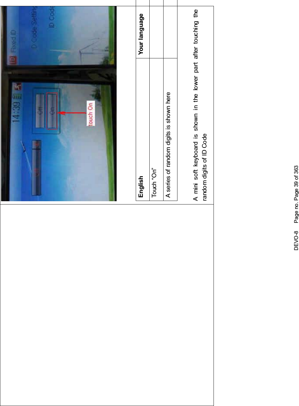
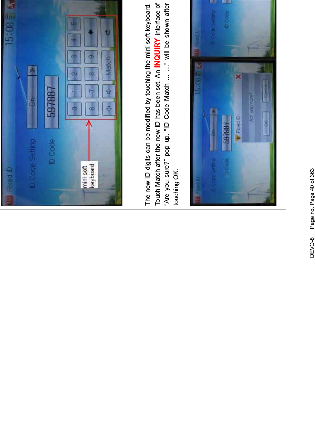
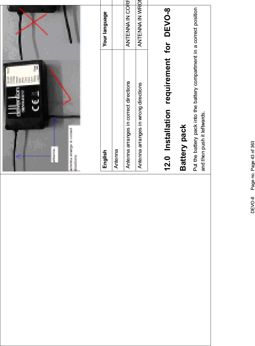
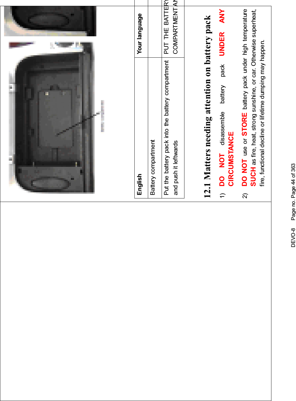
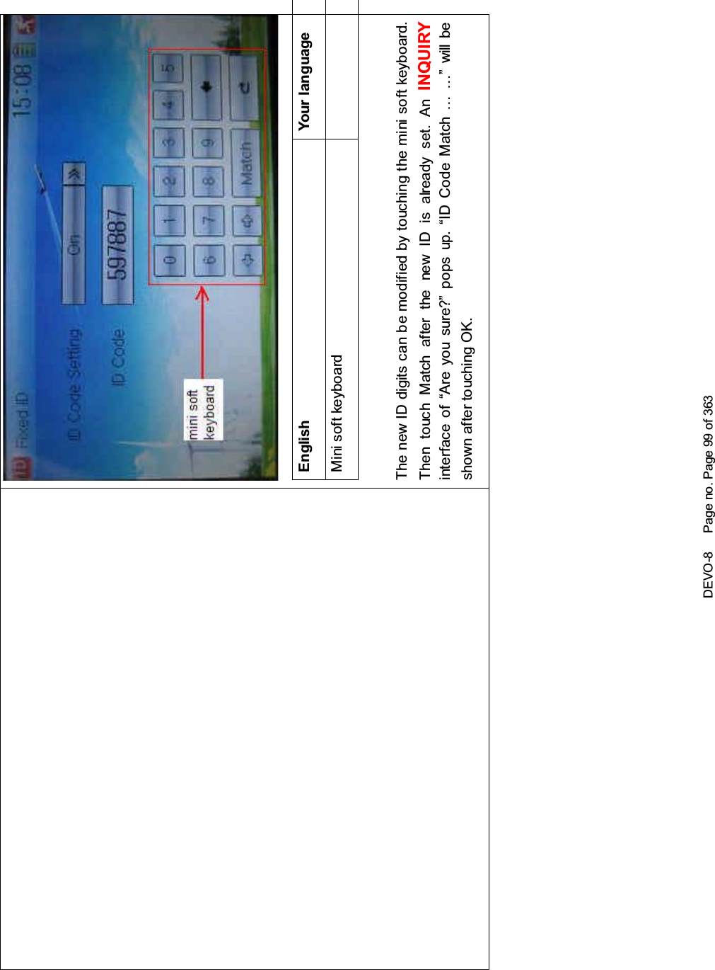
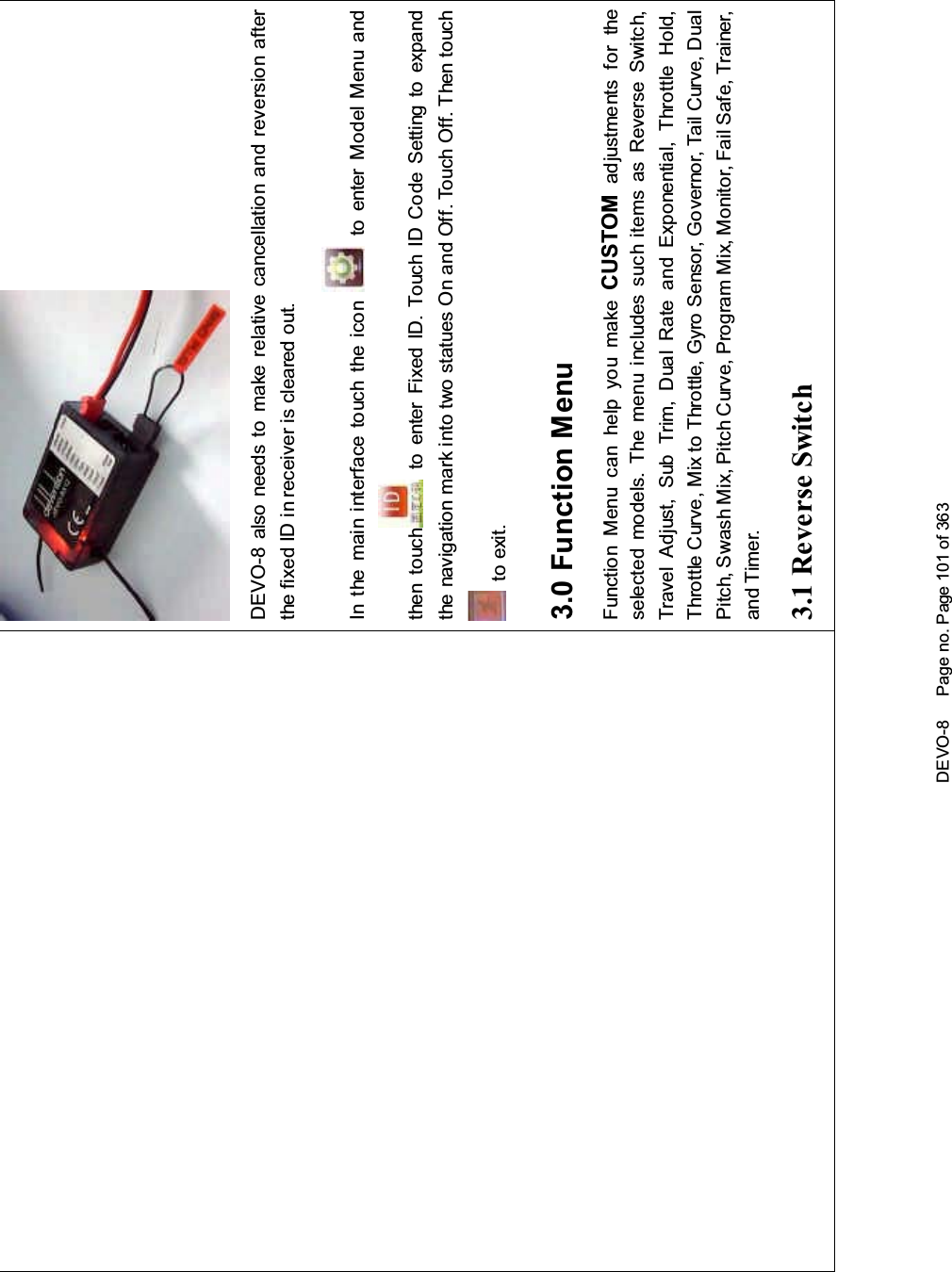
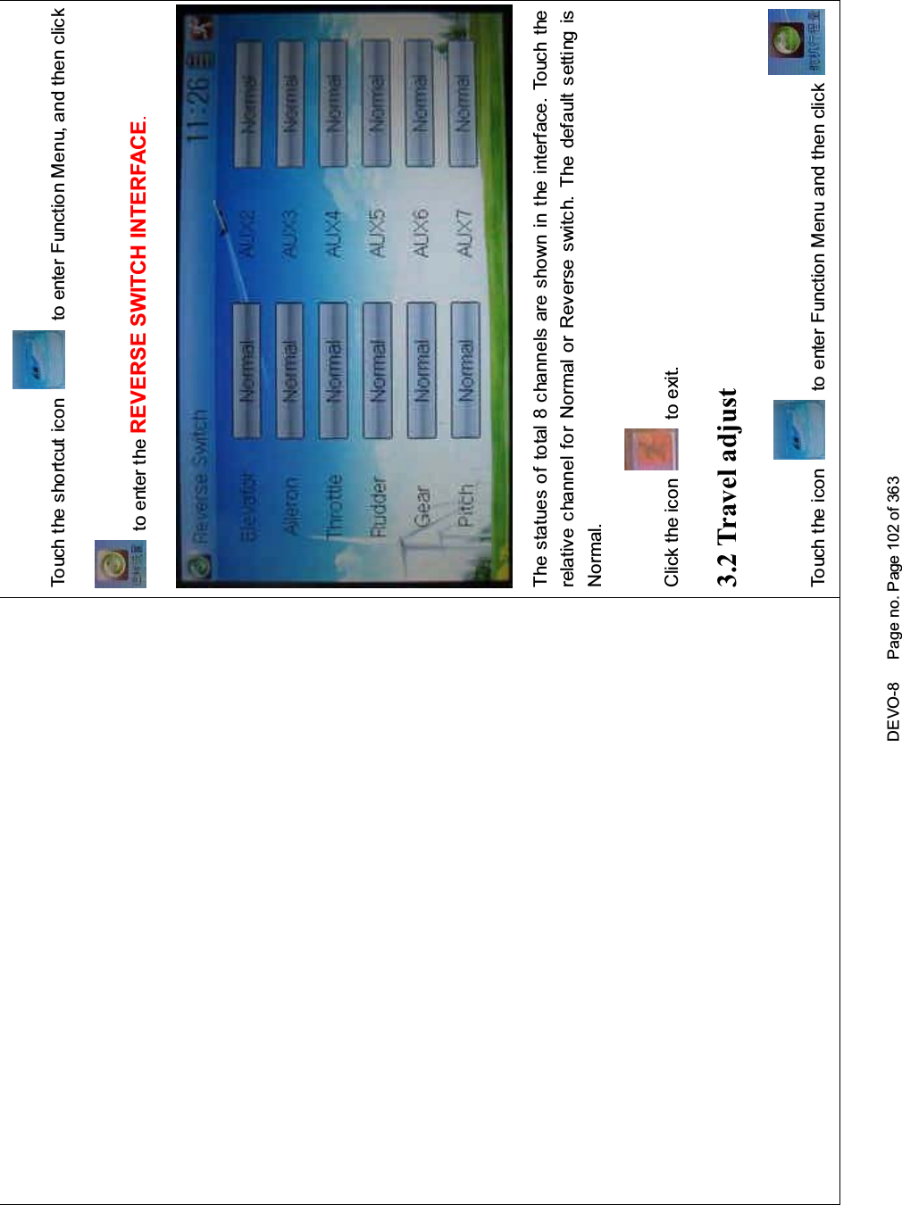
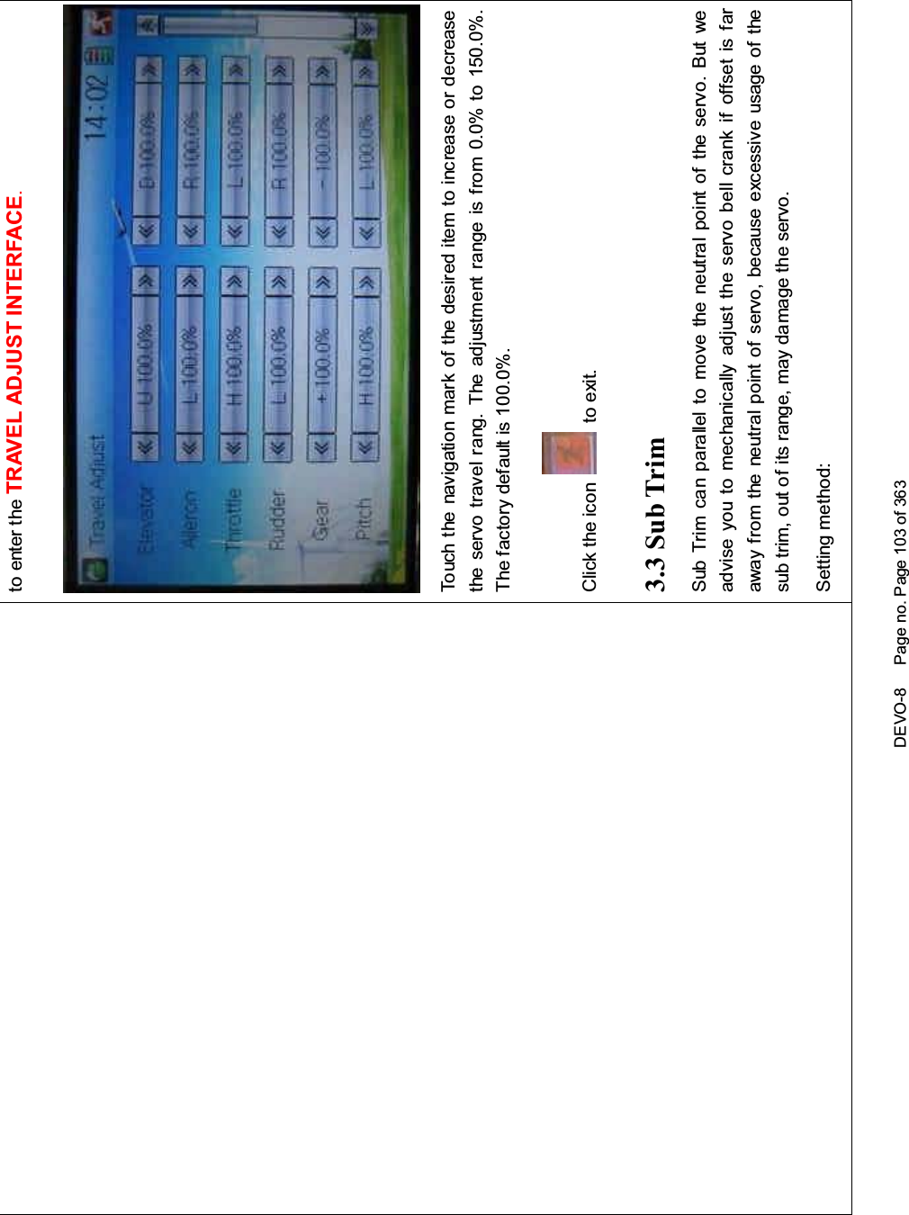
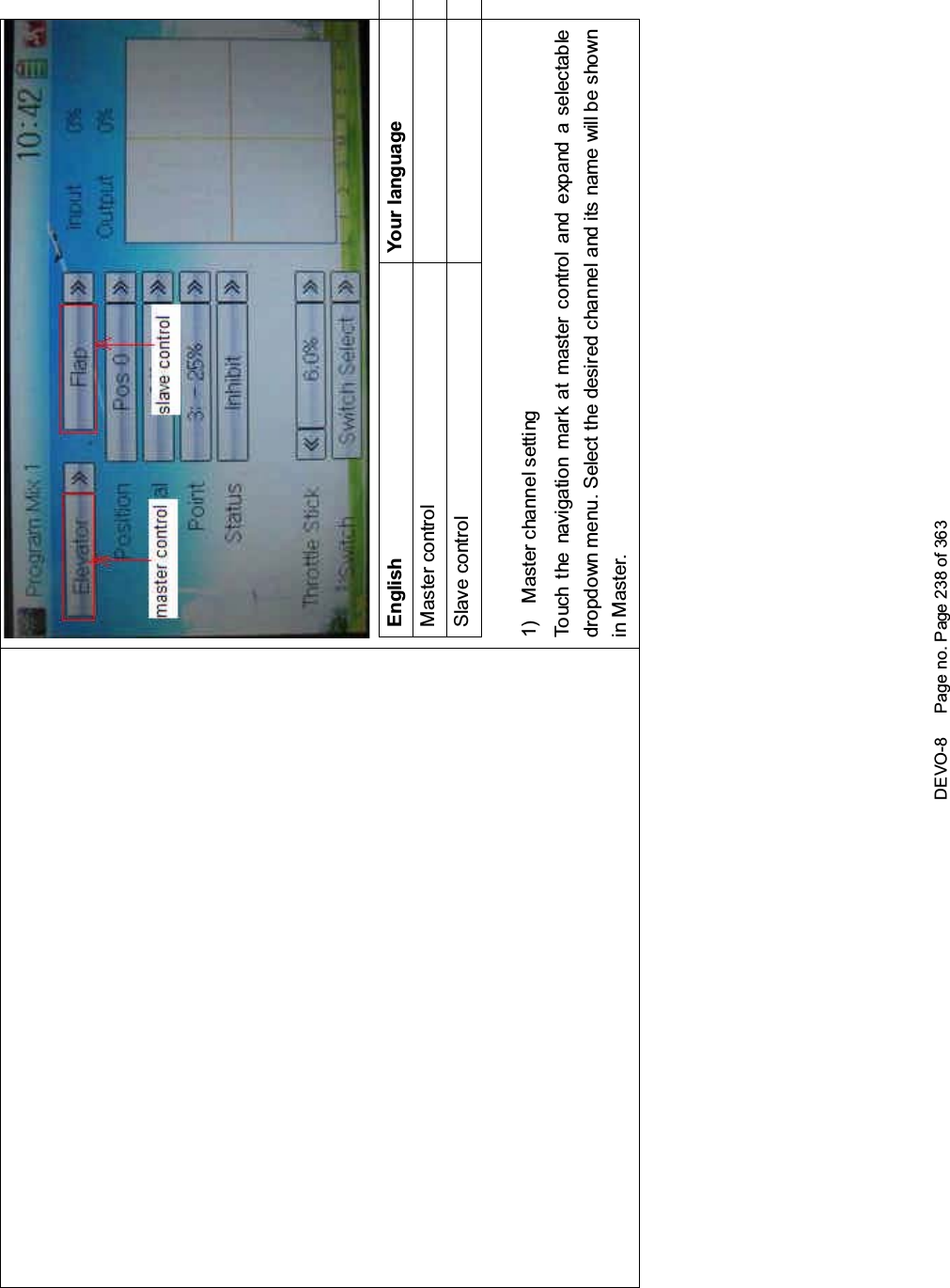
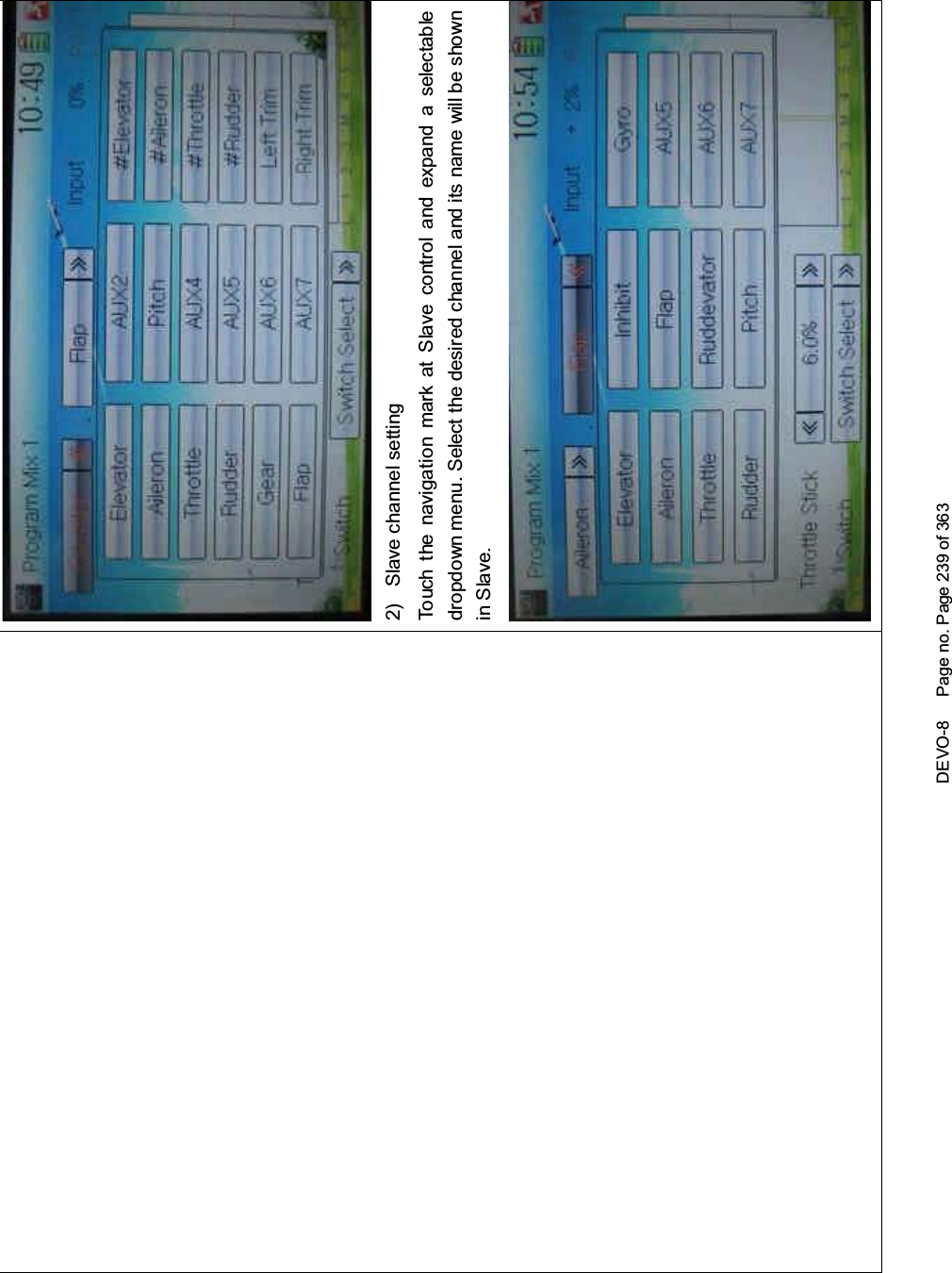
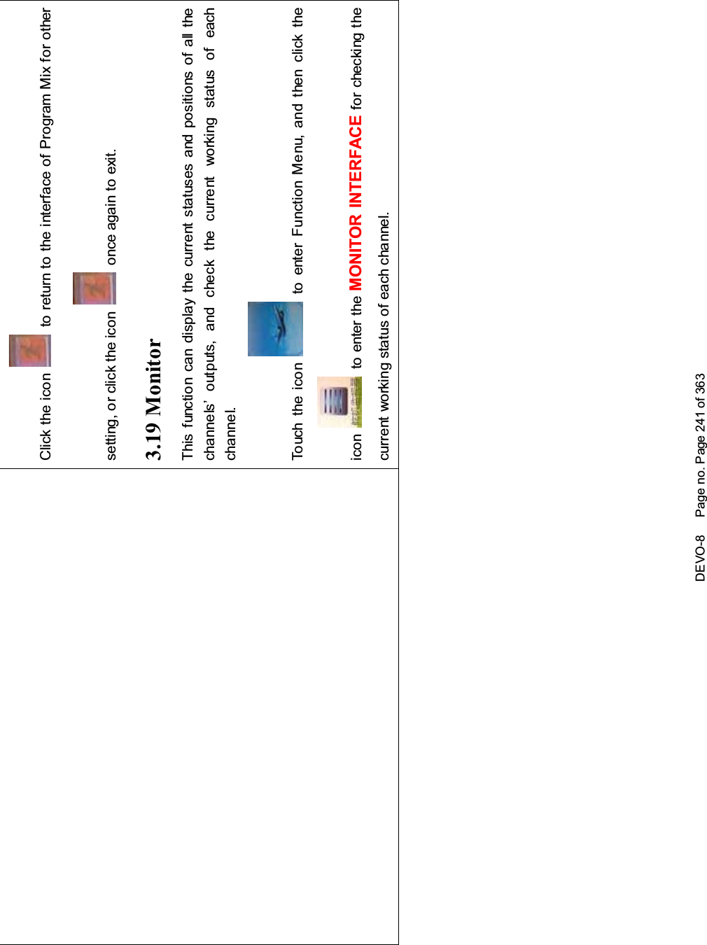
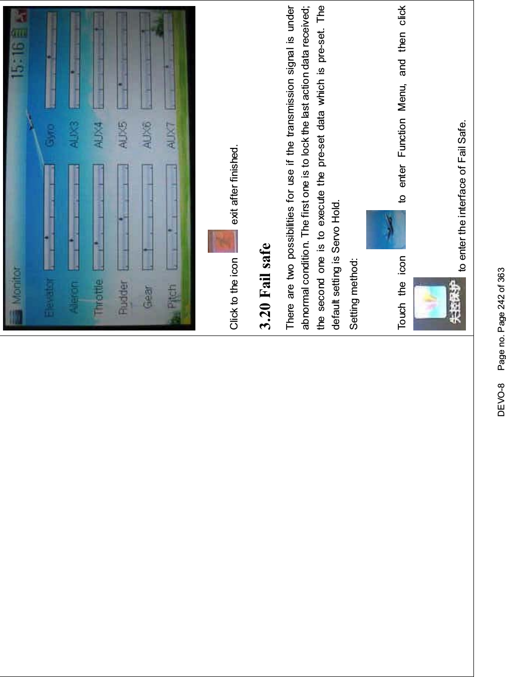
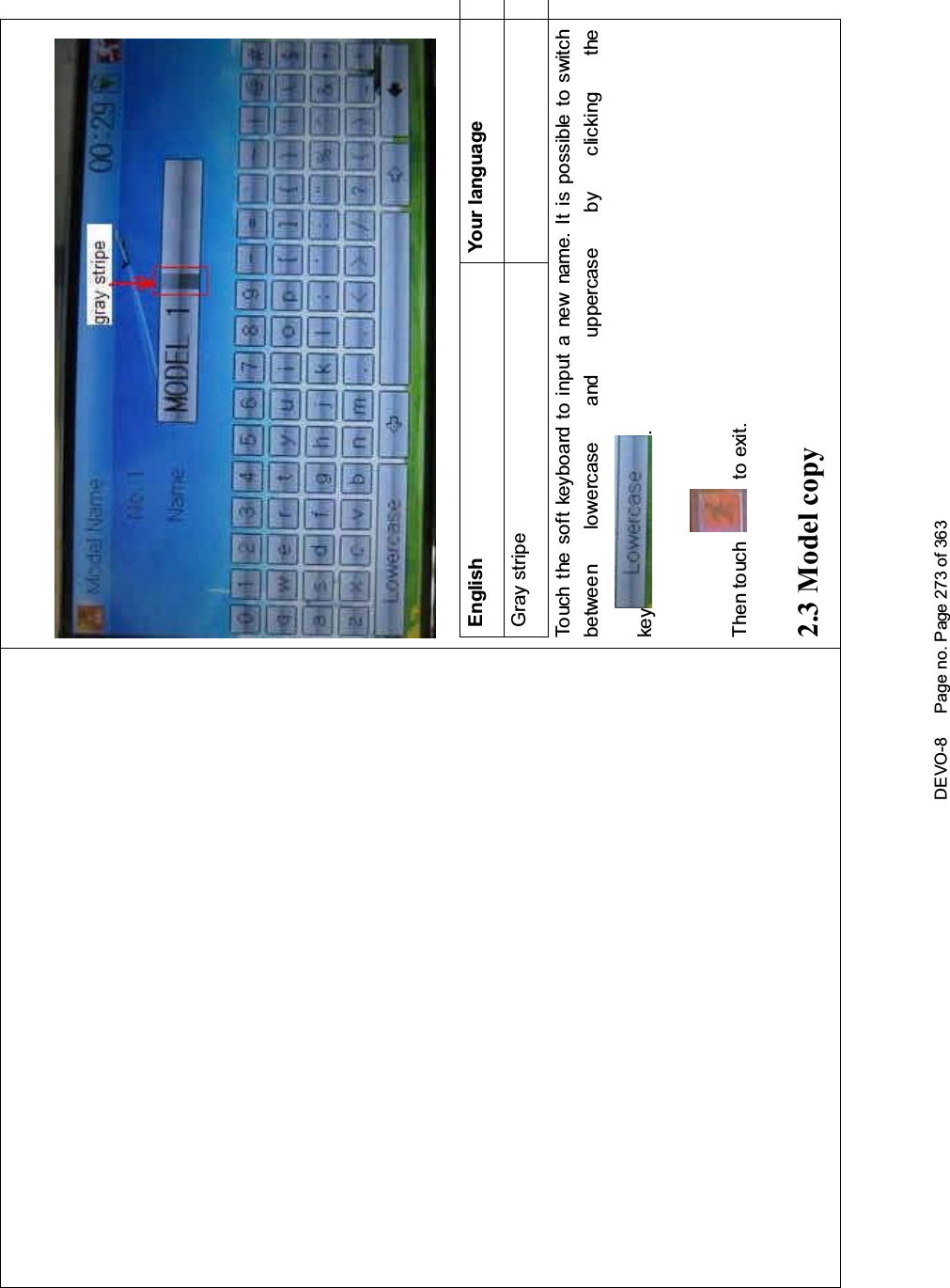
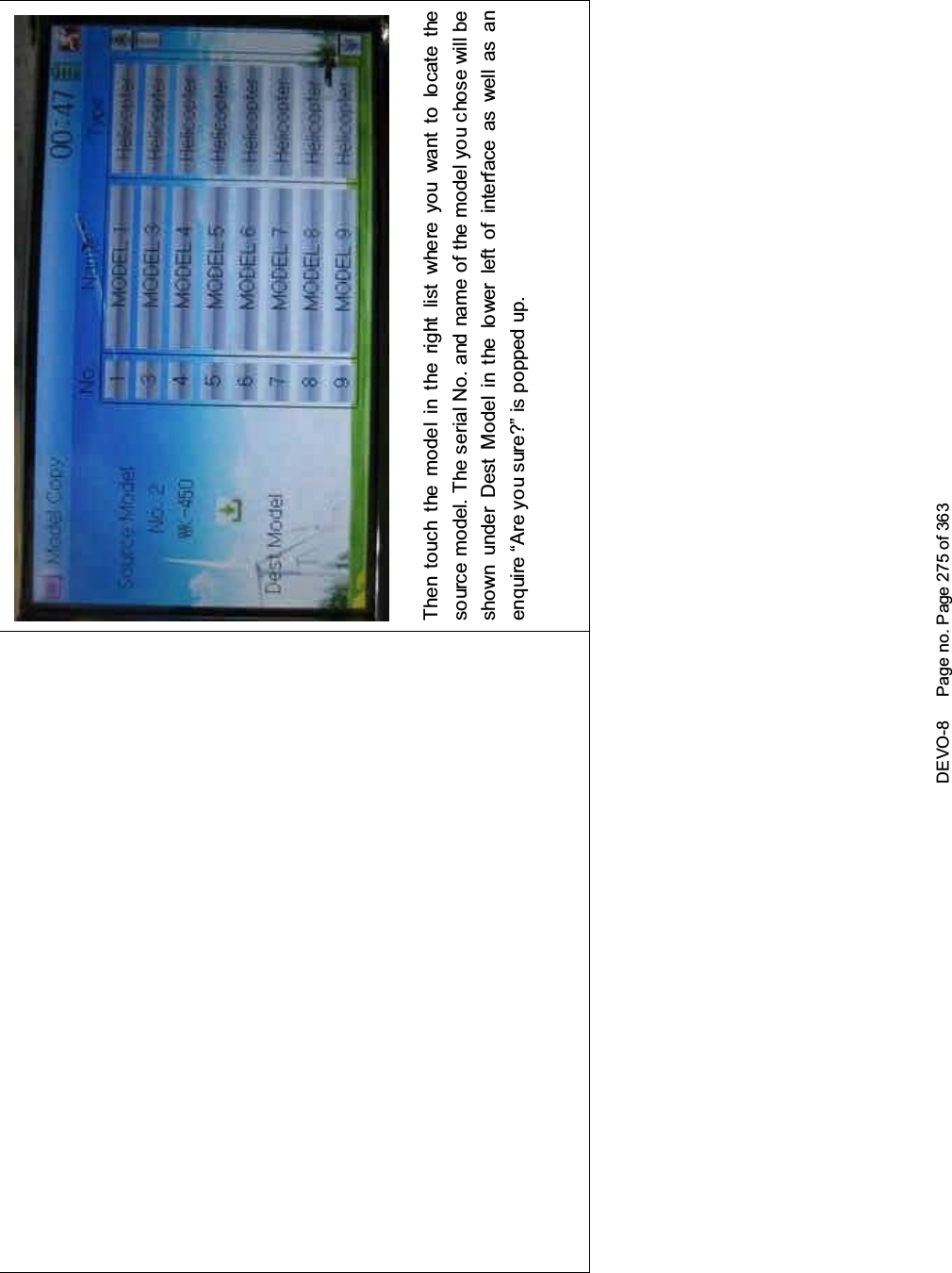
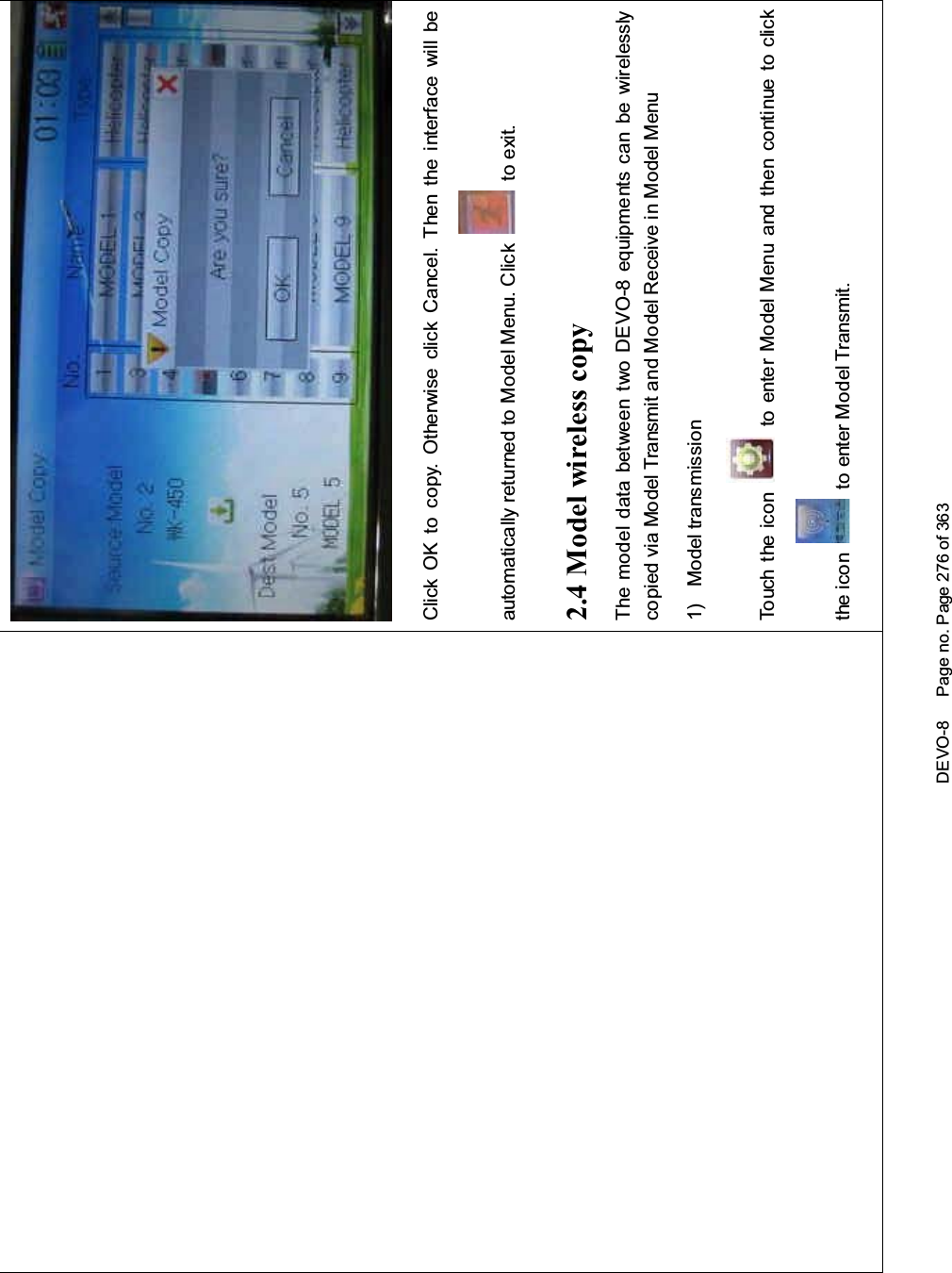
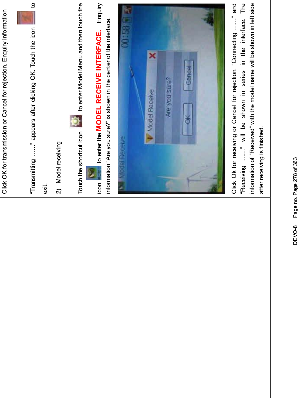
DEVO 8 User Manual
Users Manual
Navigation menu
Upload a User Manual
Namespaces
Wiki Guide
HTML
PDF
Info
Views
User Manual
Discussion / Help
Navigation