GuangZhou Walkera Technology DEVO-8 2.4G Transmitter User Manual DEVO 8 25 AUG 2011
GuangZhou Walkera Technology Co., Ltd 2.4G Transmitter DEVO 8 25 AUG 2011
Users Manual

DEVO-8 Page no. Page 1 of 363
User Manual for DEVO-8
Part one: General information7
1.0 General information...........................................................................................
.
1.1 Foreword 8
1.2 Important statements 8
1.3 Safety needing attention 9
1.4 Attention before flight 11
2.0 Features .............................................................................................................
.
2.1 Features of DEVO-8 12
2.2 Features of RX1201 13
3.0 Specification.......................................................................................................
.
3.1DEVO-8specification 13
3.2 Receiver specification 14
4.0 Definition of DEVO-8 .........................................................................................
.
4.1 Panel definition 14
4.2 Rear definition 16
4.3WiringDiagram 18
4.4 Function keys in panel 19
5.0 Control stick adjustment....................................................................................
.
5.1Controlsticklengthadjustment 20
5.2 Control stick tension adjustment 21
6.0 Neck strap usage...............................................................................................
.
7.0 Stick mode switch................................................................
...............................
8.0 Switches between left-hand and right-hand throttles.......................................
.
8.1 Right-hand throttle switched to left-hand throttle25
8.2 Left-hand throttle switched to right-hand throttle28
9.0 Training function ................................................................................................
.

DEVO-8 Page no. Page 2 of 363
10.0 Customized fixed ID ........................................................................................
.
11.0 Installation requirements for receiver................................
...............................
12.0 Installation requirement for DEVO-8 Battery pack.........................................
.
12.1 Matters needing attention on battery pack44
12.2 DEVO-8 battery charging 45
12.3 Voltage parameters 46
12.4 Indication for charging status 47
Part two: Helicopter 49
1.0 System menu.....................................................................................................
.
1.1 Language setting 51
1.2 Skin selection 52
1.3 Display 53
1.4 Buzzer warning 55
1.5 Date & Time 56
1.6 TFT screen calibration 59
1.7 Stick mode 60
1.8 Stick and lever 61
1.9 Power amplifier 65
1.10 About 66
2.0 Model menu .......................................................................................................
.
2.1 Model select 67
2.2 Model name 67
2.3 Model copy 70
2.4 Model wireless copy 72
2.5 Model reset 75
2.6 Type select 78
2.7 Trim system 79
2.8 Stick position 80
2.9 Warning 84
2.10 Device select 86
2.11 Device Output 89

DEVO-8 Page no. Page 3 of 363
2.12 Swash type 95
2.13 Fixed ID 96
3.0 Function Menu ...................................................................................................
.
3.1 Reverse Switch 101
3.2 Travel ad just 102
3.3 Sub Trim 103
3.4 Dual Rate and Exponential 105
3.5 Throttle ho ld 114
3.6 Throttle curve 117
3.7 Mix to throttle 120
3.8 Gyro sensor Error! Bookmark not defined.
3.9 Governor Error! Bookmark not defined.
3.10 Tail curve Error! Bookmark not defined.
3.11 Dual p itch Error! Bookmark not defined.
3.12 Swash mix Error! Bookmark not defined.
3.13 Pitch curve Error! Bookmark not defined.
3.14 Program mix Error! Bookmark not defined.
3.15 Monitor Error! Bookmark not defined.
3.16 Fail safe Error! Bookmark not defined.
3.17 Trainer Error! Bookmark not defined.
3.18 Timer Error! Bookmark not defined.
Part three: Airplane 122
1.0 System menu.....................................................................................................
.
1.1 Language setting 123
1.2 Skin selection 124
1.3 Display 125
1.4 Buzzer warning 127
1.5 Date & Time 128
1.6 TFT screen calibration 131
1.7 Stick mode 132
1.8 Stick and lever 133

DEVO-8 Page no. Page 4 of 363
1.9 Power amplifier 137
1.10 About 138
2.0 Model menu .......................................................................................................
.
2.1 Model select 139
2.2 Model name 139
2.3 Model copy 142
2.4 Model copy 144
2.5 Model reset 147
2.6 Type select 150
2.7 Trim system 151
2.8 Stick position 152
2.9 Warning 156
2.10 Device select 159
2.11 Device Output 161
2.12 Wing type 169
2.13 Fixed ID 179
3.0 Function Menu ...................................................................................................
.
3.1 Reverse switch 185
3.2 Travel ad just 185
3.3 Sub trim 187
3.4 Dual rate and exponential 189
3.5 Throttle ho ld 194
3.6 Throttle curve 196
3.7 Snap roll 201
3.8 Differential 203
3.9 Balance 208
3.10 Gyro s ensor 211
3.11 Governor 214
3.12 Aileron to Rudder Mix 216
3.13 Elevator to flap mix 218
3.14 Rudder to aileron/elevator mix 221

DEVO-8 Page no. Page 5 of 363
3.15 Flap system 224
3.16 Aileron to flap mix 227
3.17 Pitch curve 229
3.18 Program mix 233
3.19 Monitor 241
3.20 Fail safe 242
3.21 Trainer 244
3.22 Timer 251
Part four: Glider 254
1.0 System menu.....................................................................................................
.
1.1 Language setting 256
1.2 Skin selection 256
1.3 Display 257
1.4 Buzzer warning 259
1.5 Date & Time 260
1.6 TFT screen calibration 263
1.7 Stick mode 264
1.8 Stick and lever 265
1.9 Power amplifier 269
1.10 About 270
2.0 Model menu .......................................................................................................
.
2.1 Model select 271
2.2 Model name 271
2.3 Model copy 273
2.4 Model wireless copy 276
2.5 Model reset 279
2.6 Type select 282
2.7 Trim system 283
2.8 Stick position 284
2.9 Warning 288
2.10 Device select 289

DEVO-8 Page no. Page 6 of 363
2.11 Device Output 292
2.12 Wing type 297
2.13 Fixed ID 301
3.0 Function menu ...................................................................................................
.
3.1 Reverse switch 307
3.2 Travel ad just 307
3.3 Sub trim 308
3.4 Dual rate and exponential 310
3.5 Motor hold 316
3.6 Flaperon mix 318
3.7 Camber system 321
3.8 Differential 324
3.9 Balance 326
3.10 Gyro s ensor 328
3.11 Rudder to spoiler mix 329
3.12 Aileron to rudder mix 330
3.13 Elevator to flap mix 333
3.14 Aileron to flap mix 335
3.15 Flap to tip-aileron mix 336
3.16 Flap rate 338
3.17 Brake system 340
3.18 Program mix 342
3.19 Monitor 349
3.20 Fail safe 350
3.21 Trainer 352
3.22 Timer 359
Welcome to THE DEVO-8 transmitter.
DEVO-8 Page no. Page 7 of 363
Note: read THE MANUAL thoroughly before using, and keep it in a safe
place for the future reference.
User Manual of DEVO-8 transmitter
Part one: General information
1.0 General information

DEVO-8 Page no. Page 8 of 363
1.1 Foreword
DEVO-8 takes 2.4GHz Direct Sequence Spread Spectrum (DSSS)
technology, features automatic ID binding, automatic ID assignment,
and also features CUSTOMIZED fixed ID setup. The usage of wireless
copy function keeps you away from the trouble in wire link-up. Three
mode types of Helicopter, Airplane, and Glider are available to meet
your requirements for different models. Touch screen with wide area is
used and it offers you convenient operation. USB Online update
technology ensures one transmitter in hand forever not to be out of date
and makes it full of vigor.
1.2 Important statements
1) The transmitter is suitable for experienced radio controlled aircraft
modelers beyond 14 years old.
2) Flying the model aircraft in approved ground is a must.
3) We are not responsible for any safety caused by operation, usage
orcontrolassoonasthetransmitterissoldout.
4) We consign our distributors to offer technical support and service
after sale. Please contact the local distributors for problem
solutions caused by usage, operation, maintenance, etc.

DEVO-8 Page no. Page 9 of 363
1.3Safetyneedingattention
1) Far away from obstacle and people.
RC aircraft in flights is uncertai n of flight speed and status, which
potential risk exists in when flying. Please keep your radio controlled
aircraft far away from people, high buildings, high-tension line, etc, and
avoid operating in rain, storms, thunder and lightening.
2) Away from HUMID environment
Radio controlled aircraft should be kept away from humidity and vapor
because it is composed of complicated precise electronic elements and
MECHANICAL parts.
3) Proper operation
Use original spare parts to upgrade, modify or maintain your equipment
in order to assure its safety. Please operate your equipment within the
range of functions permitted. It is forbidden to use out of the safety laws
or regulations.
4) Safety operation
Operate your equipment according to your body status and flight skills.
Fatigue, listlessness and mis-operation will increase the possibilities of
accidental hazard.
5) Away from heat sources
The inside of the transmitter is composed of precise electronic

DEVO-8 Page no. Page 10 of 363
components and mechanical parts. Keep it far away form heat sources
and sunshine to avoid distortion, or even damage caused by high
temperature.
6) Correct charging method
Use the assorted charger to charge the battery for your DEVO-8. The
usage of the charger should be within the range of rated voltage.

DEVO-8 Page no. Page 11 of 363
1.4 Attention before flight
1) Ensure the battery packs of both transmitter and receiver are fully
saturated.
2) Ensure both the throttle stick and the throttle trim of your DEVO-8
stay at the lowest positions before operation.
3) Strictly obey the order of TURN-ON and TURN-OFF before
operation. When starting yo ur flight, turn on your DEVO-8 first, and
connect the battery to the aircraft last. When turning off the aircraft,
disconnect the battery first, and turn off your DEVO-8 last. An upset
in the order may cause your aircraft out of control. Cultivate a
correct habit of turn-on and turn-off.
4) Ensure whether the directions and actions of all the servos in your
RC aircraft are correct when executing commands of the
transmitter. Using broken servos will result in unforeseen dangers.

DEVO-8 Page no. Page 12 of 363
2.0 Features
2.1 Features of DEVO-8
1) The DEVO-8 adopts 2.4 GHz Direct Sequence Spread Spectrum
(DSSS) technology and features both automatic ID binding and ID
assignment. It can also be customizedly set as fixed ID code.
2) USB online update makes you always enjoy the latest program.
3) Hi-frequency output power is adjustable.
4) Wireless data transmission between two DEVO-8 helps experience
the training function.
5) Up to 60-model data can be saved.
6) DEVO-8 adjusting the gyro sensitivity makes hovering flight and
fancyflightinaneasyway.
7) Ultra big size TFT touch screen with graphic interface features
direct and convenient setting.
8) Shape design accords with human engineering, and provides
comfortable holding.
9) Both the length and tension of the sticks can be amendable.
10) DEVO-8 can be freely switched among Modes 1, 2, 3, and 4.
11) DEVO-8 is suitable for Helicopter, Airplane, and Glider. In the

DEVO-8 Page no. Page 13 of 363
Helicopter mode, there are three flight modes, each of which can
be freely set and whose parameters can be personalizedly
adjusted to meet the requirement for F3C or 3D aerobatic flight.
2.2 Features of RX1201
1) Adopt 2.4GHz Direct Sequence Spread Spectrum (DSSS) that
features fast reaction and strong anti-jamming protection.
2) Double receiving circuits effectively assure stability of receiving
signal.
3) The single chip as CPU provides super-strong analyzing ability.
4) RX-12 maintains memories of both the frequency and ID code
when it is changed a new battery pack with DEVO-8 powered on
5) It can be set as a custom fixed ID and automatic ID assignment. .
3.0 Specification
3.1 DEVO-8 specification
Encoder ………………………..8-channel micro computer system
Frequency ……………………... 2.4GHz DSSS
2XWSXWSRZHU«««««««P:

DEVO-8 Page no. Page 14 of 363
&XUUHQWGUDLQ««««««««P$DWP:
Power supply ………………….... 5# Dry cell 4*1.5V, or NiMH 4*1.2V
1,600 - 2,000 mAh
Output pulse ……………………. 1000 – 2000 mS (1500 Neutral)
3.2 Receiver specification
Type ………………………………2.4GHz 8 channels
Sensitivity ……………………….. - 105 dbm
)UHTXHQF\LQWHUYDO««««««0
Weight …………………………… 9.5 g
Dimension ………………………. 38X28.5X14.5mm
RX power supply ……………..4.8-6V 1,300mAh
4.0 Definition of DEVO-8
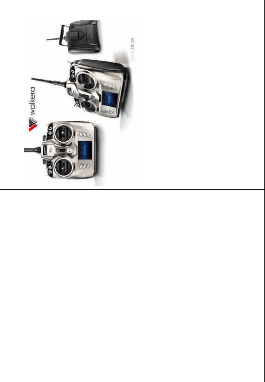
4.1 Panel definition
DEVO-8 Page no. Page 15 of 363
1ˊ㒓 / Antenna
2ˊᦤᡞ /Handle
3ˊᎺᖂ䇗 / Left trim
4ˊᮍ㠉ᇣ㠉䞣ߛᤶᓔ݇ / RUDD D/R
5ˊछ䰡㠉ᇣ㠉䞣ߛᤶᓔ݇ /ELEVD/R
6ˊ䍋㨑ᶊᓔ݇ / Gear
7ˊELEV/RUDD ᨛᴚ / ELEV/RUDD stick
8ˊELEV ᖂ䇗 /ELEVtrim

DEVO-8 Page no. Page 16 of 363
9ˊRUDD ᖂ䇗 /RUDD trim
10ˊEXT 䬂/EXT
11ˊUP+䬂/UP+
12ˊDN-䬂/DN
13ˊ⬉⑤ᓔ݇ /Powerswitch
14ˊেᖂ䇗 / Right trim
15ˊFMOD
16ˊAILE D/R
17ˊMIX
18ˊTHRO/AILE ᨛᴚ / THRO/AILE stick
19ˊTHRO ᖂ䇗 / THRO trim
20ˊAILE ᖂ䇗 /AILEtrim
21ˊENT 䬂/ENT
22ˊR+䬂/R+
23ˊL-䬂/L-
24ˊᰒ⼎ሣ / Screen
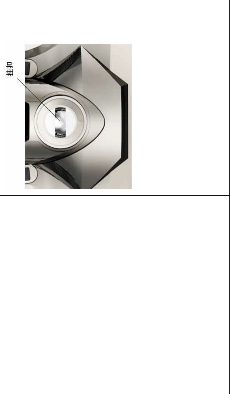
25ˊᣖষ / Eyelet
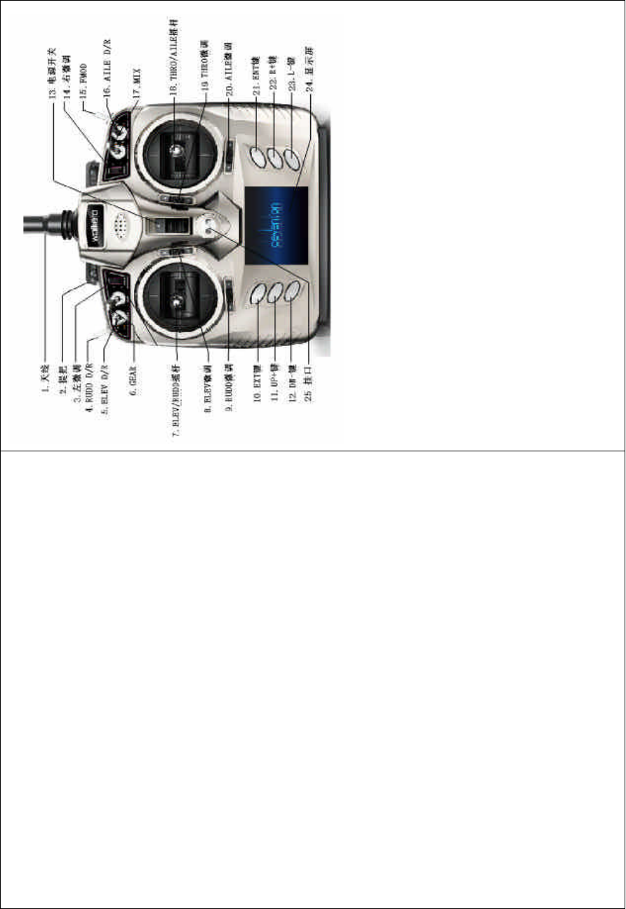
4.2 Rear definition
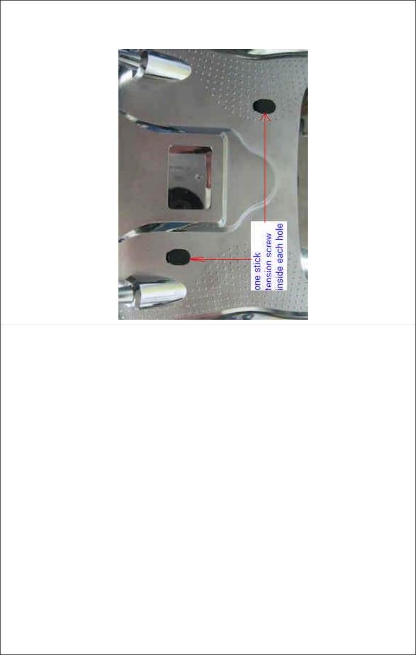
DEVO-8 Page no. Page 17 of 363
1. Regulation holes for throttle stick tension.
2. Charge socket (CHG): input DC at 8-12V, 200 mA;
Polarity: .
3. Battery compartment cover
4. Digital Signal Converter socket (DSC): for simulator flight
practice via computer (You need software and its dongle which
are available in hobby shops, and for training.
DEVO-8 Page no. Page 18 of 363
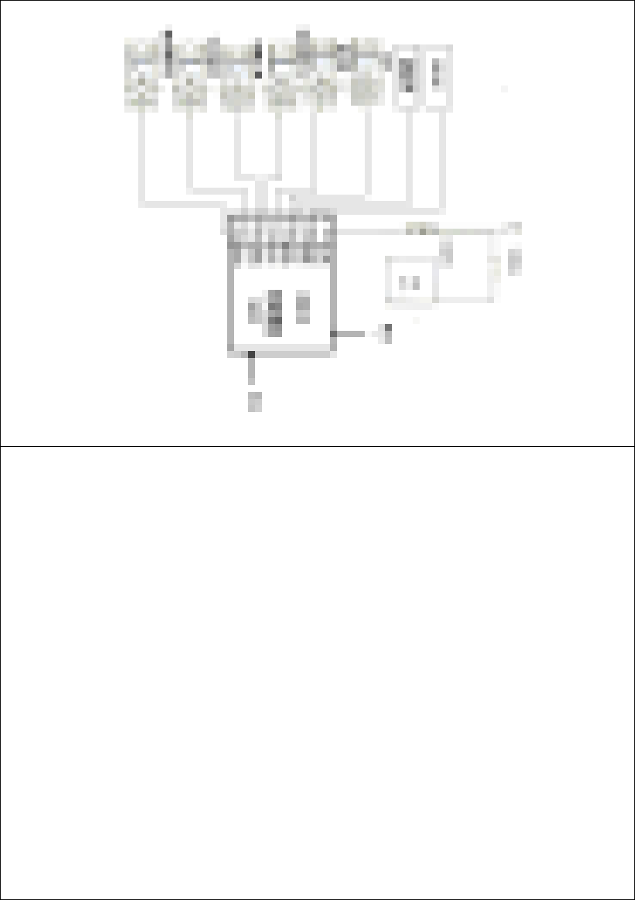
4.3 Wiring Diagram
ᬊ఼ Receiver/ DEVO-RX801
㒓 / Antenna
⬉∴ / Battery

DEVO-8 Page no. Page 19 of 363
⬉⑤ᓔ݇ /Powerswitch
ܙ⬉༈ /Chargejack
छ䰡㠉㠉ᴎ / Elevator servo
ࡃ㗐㠉ᴎ / Aileron servo
⊍䮼㠉ᴎ / Throttle servo
ᮍ㠉㠉ᴎ / Rudder servo
䍋㨑ᶊ㠉ᴎ / Gear servo
䕙ࡽ䗮䘧 1/AUX1
䕙ࡽ䗮䘧 2/AUX2
䕙ࡽ䗮䘧 3/AUX3
4.4 Function keys in panel
There are 6 functional keys in the panel of DEVO-8. Below are the
details:
1) EXT: Resetting key. Press EXT to exit the menu.
2) ENT: Confirmation key. Press ENT to get access to the system or
the function mode.
3) UP+: Function-selecting key. Move cursor up to the forward
functio n item.
4) DN-: Function-selecting key. Move cursor down to the next function
item.
5) R+: Move cursor rightwards to increase the setting value.
6) L-: Move cursor leftwards to decrease the setting value.

DEVO-8 Page no. Page 20 of 363
5.0 Control stick adjustment
The control stick adjustment includes two parts: length adjustment and
tensio n adjustment.
5.1 Control stick length adjustment
1) Prolong the stick length: Counter clockwise rotate the stick head
until the length you desire, and then counter clockwise tighten the
stick sleeve.
2) Shorten the stick length: Clockwise rotate the stick sleeve until the
length you desire, and then clockwise tighten the stick head.
ᶘ༈ / stick head
DEVO-8 Page no. Page 21 of 363
ᶘ༫ㄦ / stick sleeve
5.2 Control stick tension adjustment
Clockwise rotate the stick tension screw through the regulation hole in
the REAR panel of DEVO-8 for tightening the tension of the
corresponding stick by a Phillips screwdriver, and counterclockwise
rotate the stick tension screw for loosening the tension.
6.0 Neck strap usage
The neck strap can be connected to the eyelet. The eyelet located at
the center helps to get the best balance of your DEVO-8.
DEVO-8 Page no. Page 22 of 363
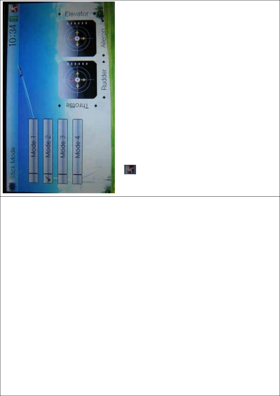
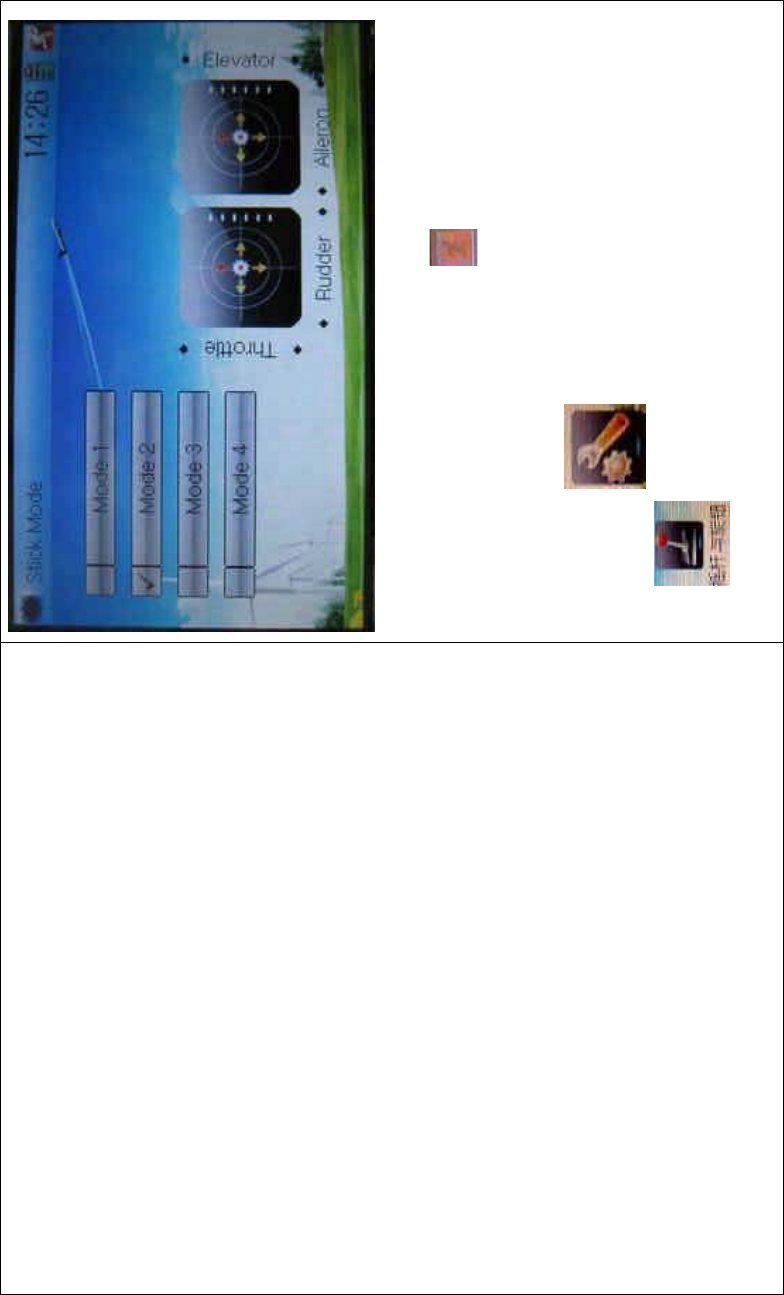
7.0 Stick mode switch
There are total four stick modes from MODE 1 through MODE 4. The
left-hand throttle contains MODE 2 and MODE 4, and the right-hand
throttle includes MODE 1 and MODE 3. Below are the sketch maps:
1) Left-hand stick includes MODE 2 and MODE 4.
MODE 2
DEVO-8 Page no. Page 23 of 363
MODE 4
2) Right-hand stick includes MODE 1 and MODE 3.
MODE 1
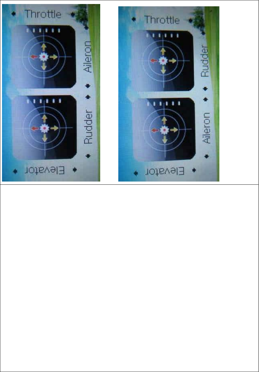
DEVO-8 Page no. Page 24 of 363
MODE 3
8.0 Switches between left-hand and
right-hand throttles
DEVO-8 Page no. Page 25 of 363
The throttle switches between the left hand and right hand will be
successful if both the MECHANICAL switch and ELECTRONIC switch
are finished, separately. Below are the methods for switching.
8.1 Right-hand throttle switched to left-hand
throttle
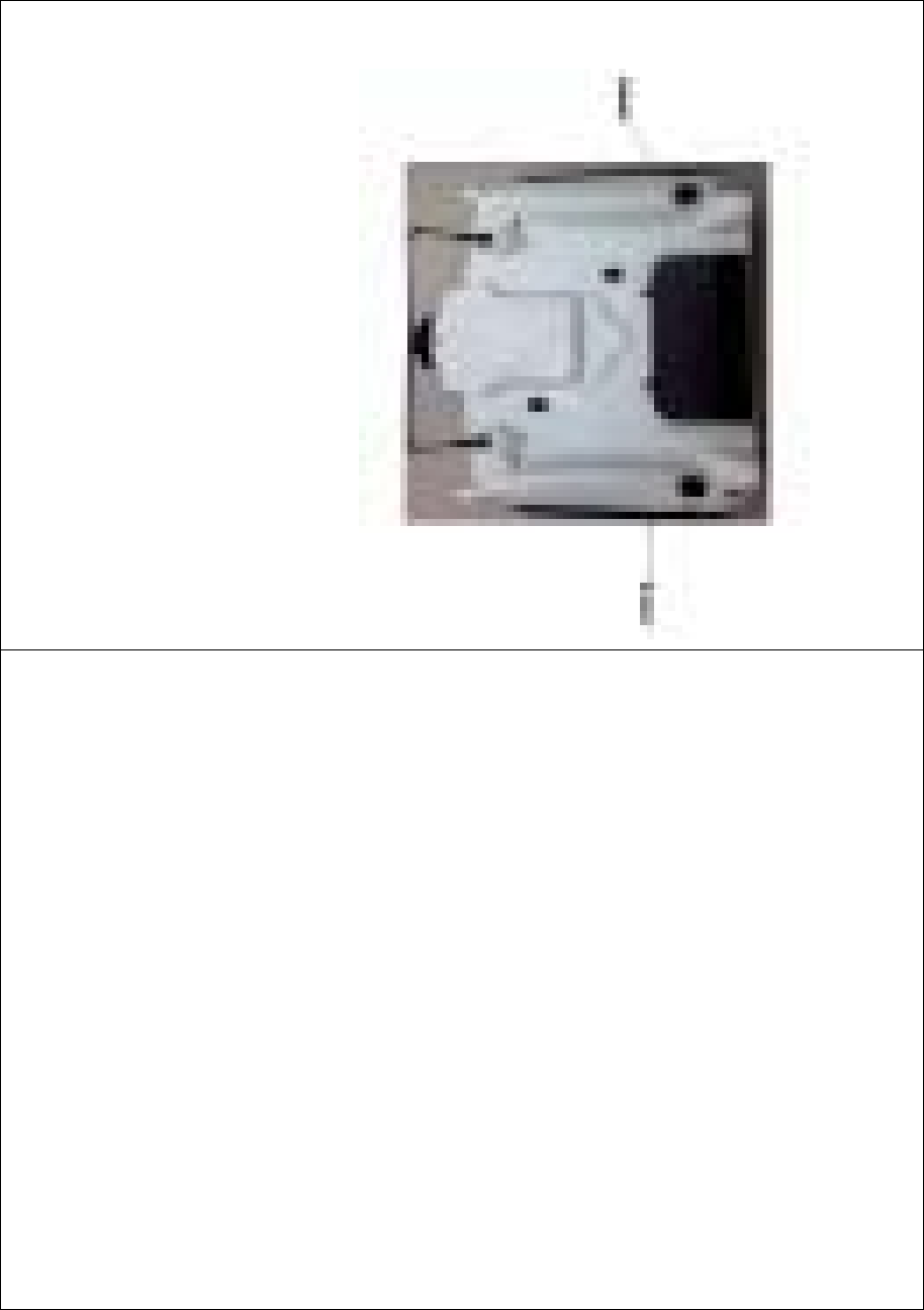
1) MECHANICAL switch
Open the battery compartment cover in the rear of your DEVO-8. Push
rightwards and take out the battery pack.
েջ䕃㛊 / Right non-slippi ng block
Ꮊջ䕃㛊 / Left non-slipping block
DEVO-8 Page no. Page 26 of 363
Remove the left lateral and right lateral non-slipping blocks,
respectively.
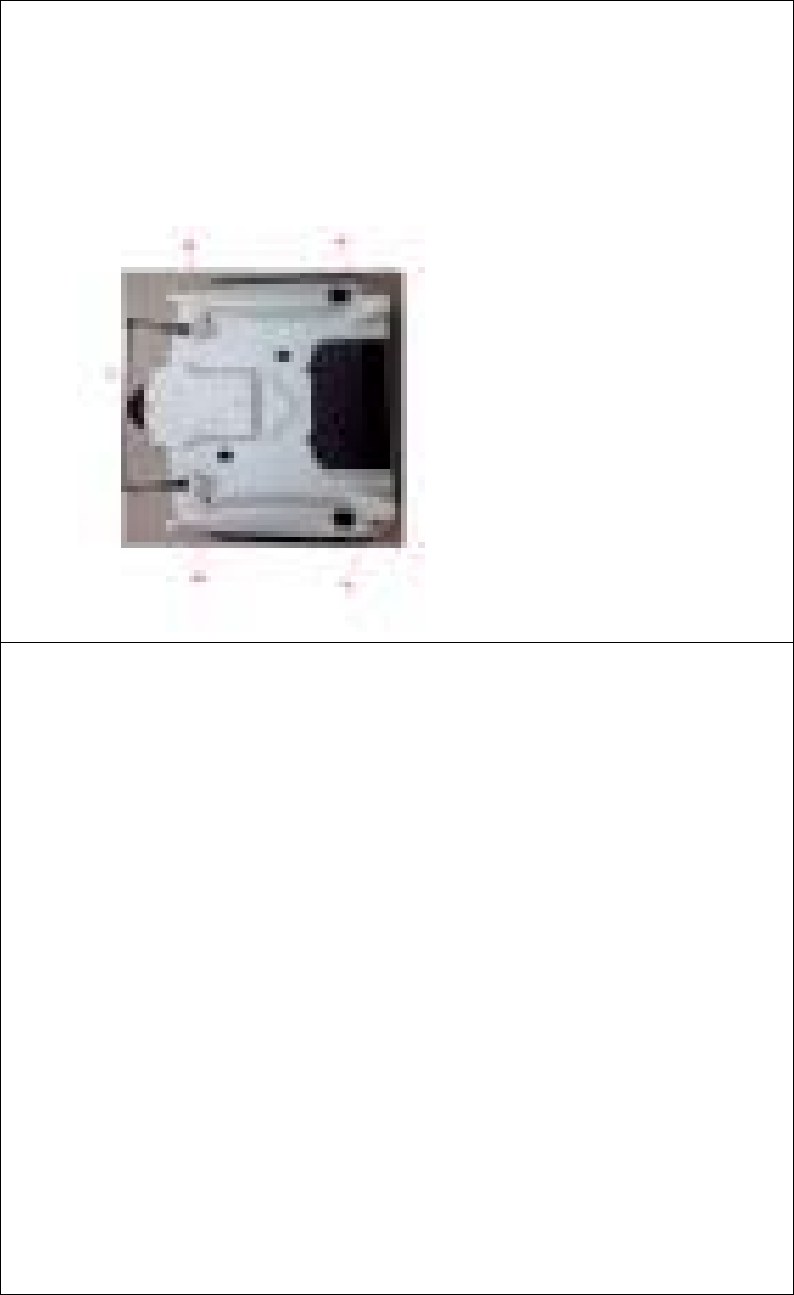
Remove the fixed screws A, B, C, D, and E, and then remove the base
plate.
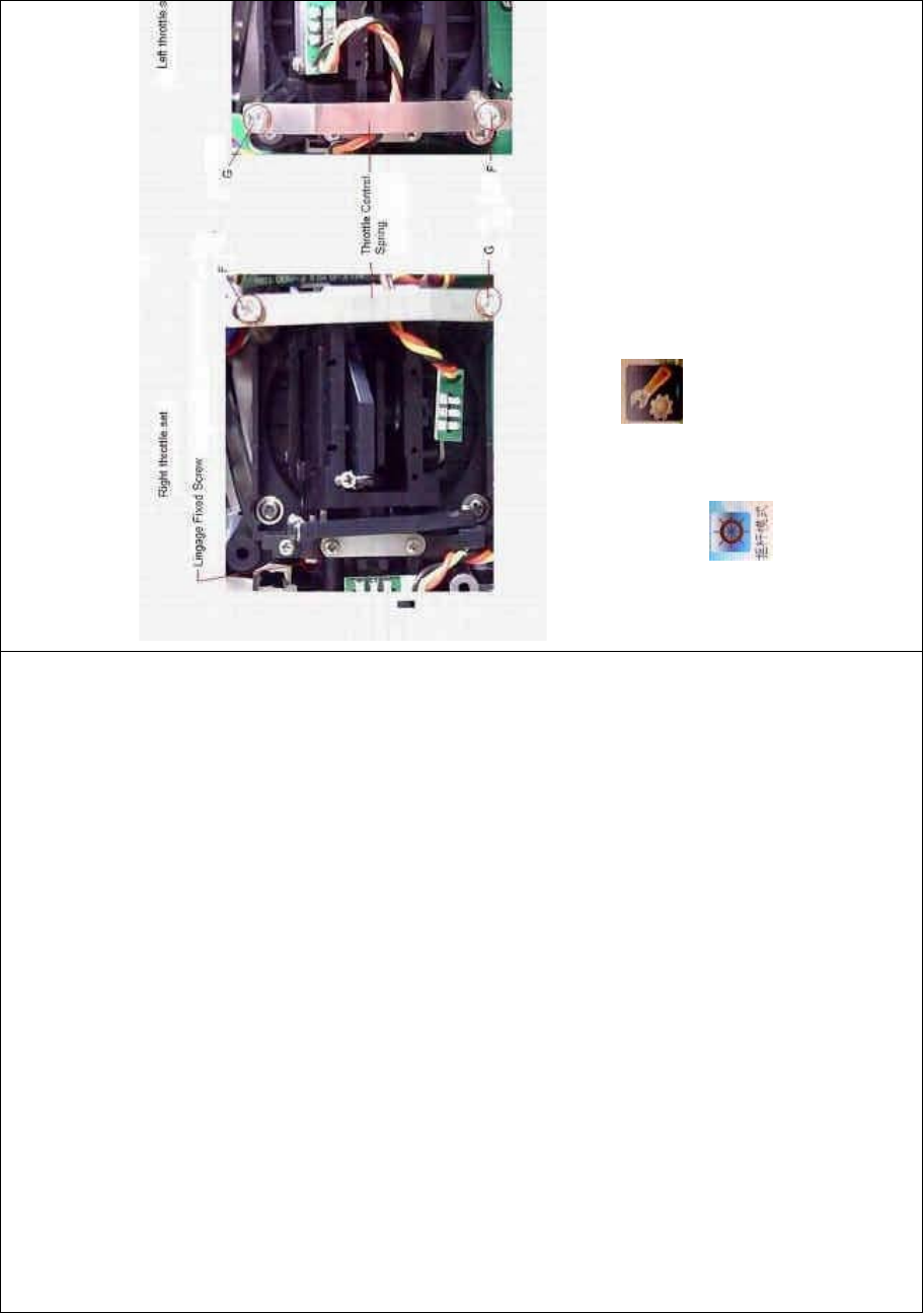
Below are shown the inside views of left and right throttle sets,
respectively. Use cross screwdriver to loosen and remove Linkage
Fixed Screw, Screw F, Screw G, and Throttle Control Spring in right
throttle set, respectively, and then mount them in the corresponding
positions in left throttle set. And then adjust the stick tension according
to your habit.
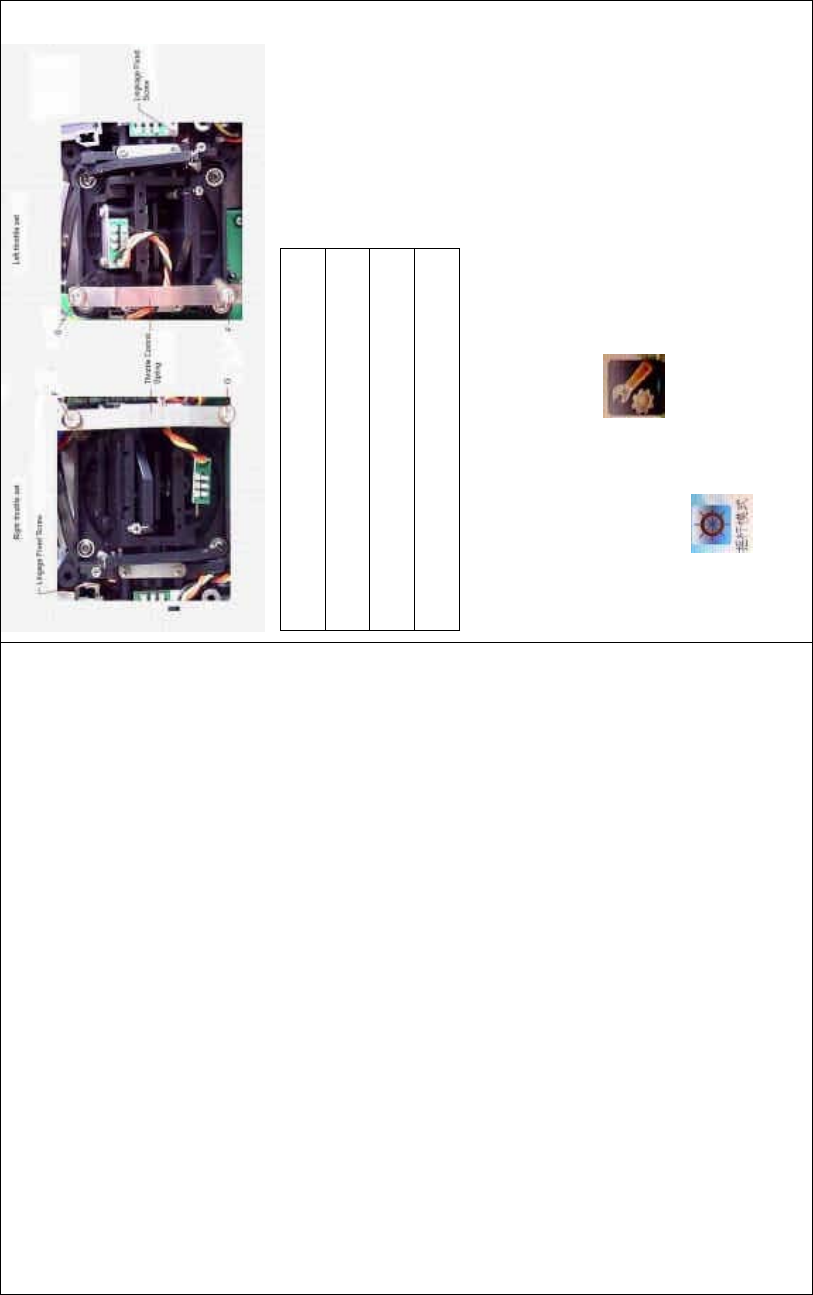
DEVO-8 Page no. Page 27 of 363
Right throttle set
Left throttle set
Linkage Fixed Screw
Throttle Control Spring
2) ELECTRONIC switch
Touch the shortcut icon to enter System Menu, and then touch
the icon to enter the STICK MODE INTERFACE,andthen
select the mode you desire.
DEVO-8 Page no. Page 28 of 363
To uc h to save and exit after the selection is finished.
The switch from right-hand t hrottle to left-hand throttle is finished after
both the MECHANICAL and ELECTRONIC switches changed,
respectively. And the transmitter is ready to normally work now.
8.2 Left-hand throttle switched to right-hand
throttle
1) MECHANICAL switch
Refer to the above “MECHANICAL switch” to open the transmitter
cover.
Below are shown the inside views of left and right throttle sets,
respectively. Use cross screwdriver to loosen and remove Linkage
DEVO-8 Page no. Page 29 of 363
Fixed Screw, Screw F, Screw G, and Throttle Control Spring in left
throttle set, respectively, and then mount them in the corresponding
positions in right throttle set. And then adjust the stick tension according
to your habit.
2) ELECTRONIC switch
Touch the shortcut icon to enter System Menu, and then touch
the icon to access to Stick Mode.
The model data will be automatically switched when touching MODE 1
or MODE 3.
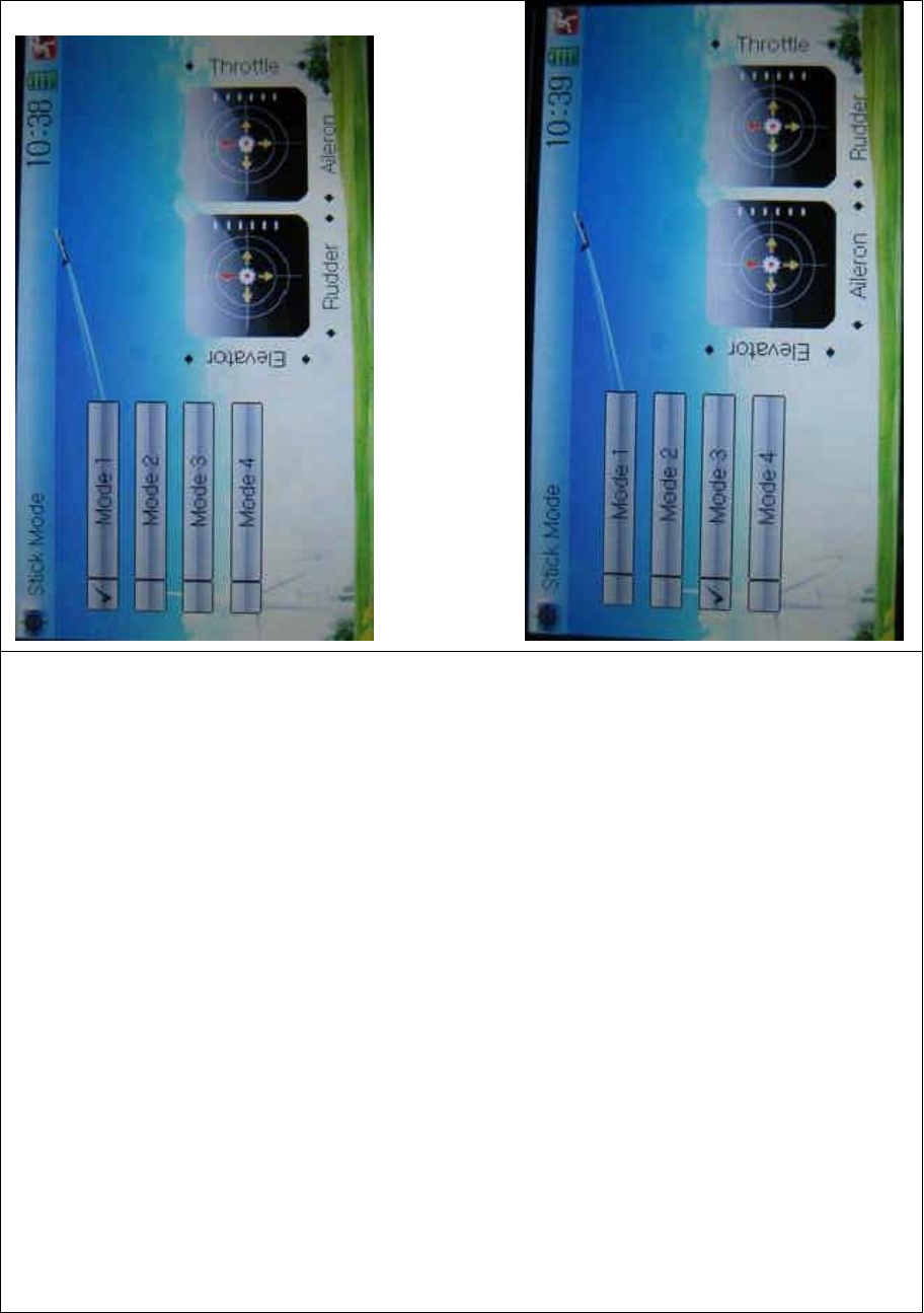
DEVO-8 Page no. Page 30 of 363
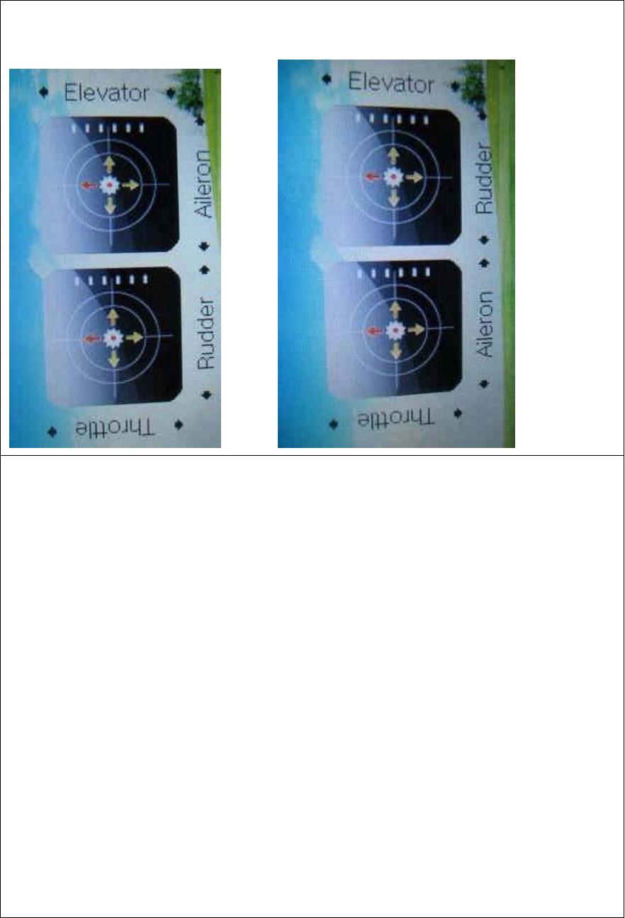
The left- and right-stick positions are shown, respectively, in the lower
right corner when MODE 1 is selected.

DEVO-8 Page no. Page 31 of 363
The left- and right-stick positions are shown, respectively when MODE
3 is selected.
To uc h to save and exit after the selection is finished.
The switch from left-hand throttle to right-hand throttle is finished after
both the MECHANICAL and ELECTRONIC switches changed,
respectively. And the transmitter is ready to work normally.
Note: pay attention to the force when rotating the screws. Excessive
forces may damage them.
9.0 Training function
Two DEVO-8s working together can execute the training function to
meet t he requirements for the begi nners. T he setti ng met hod is shown
as below:
1) Data copy
Using the wireless copy function of two DEVO-8 equipments, the model
data saved in the trainer’s one can be transmitted to the trainee’s to
ensure that the model parameters are exactly same. Regarding the
copying method, refer to “2.4 Model Wireless Copy” at “Part Two:
Helicopter”. Then follow the steps below:
2) Linkage

DEVO-8 Page no. Page 32 of 363
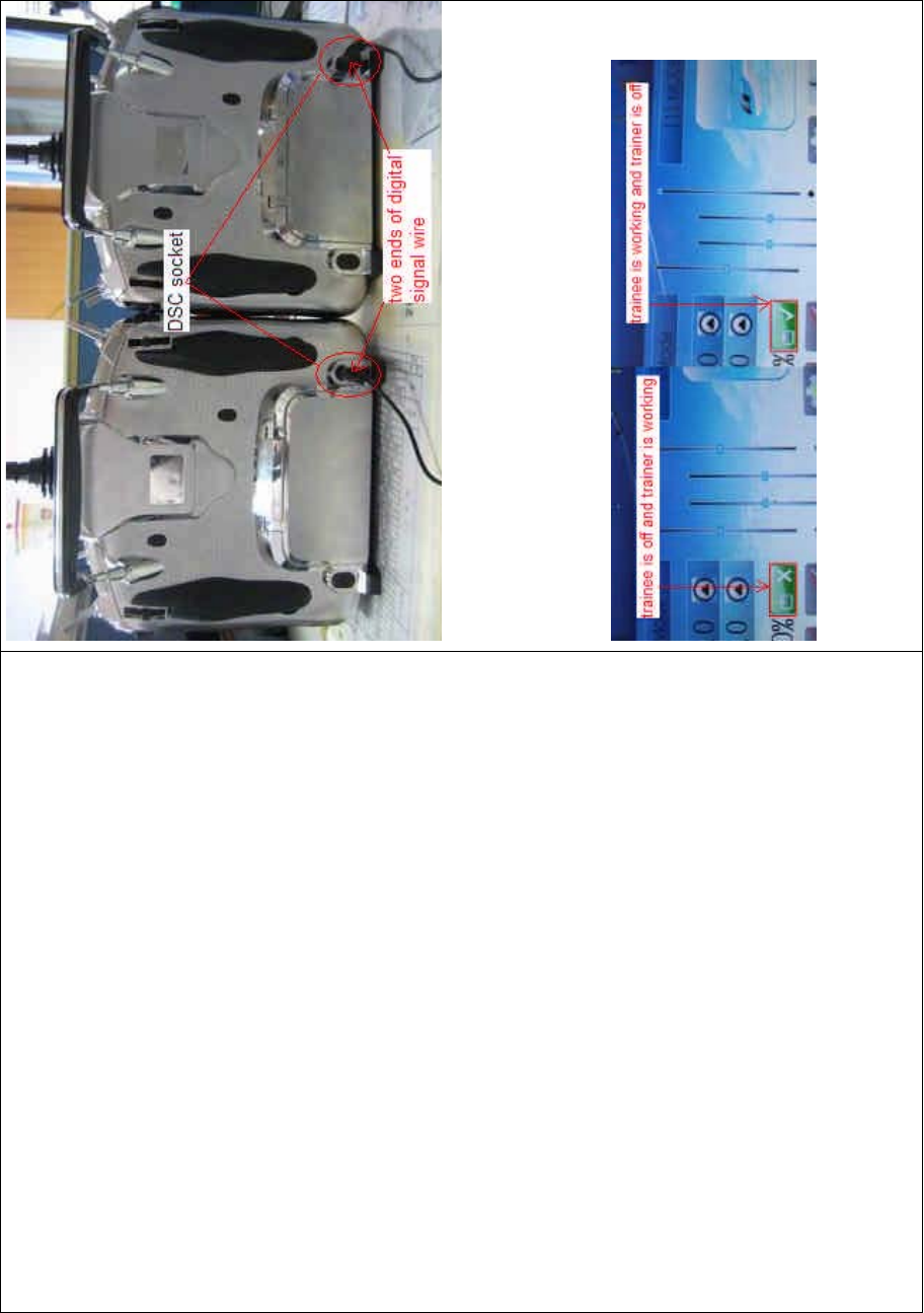
2.1) Treatment of trainee’s DEVO-8
Insert one end of the signal wire into DSC socket at the rear face of the
trainee’s DEVO-8, and then turn on the power. A linkage icon will be
shown on the boot screen. Find out the trainee’s model data at its
DEVO-8.
㘨ᴎᷛ / linkage icon
2.2) Treatment of trainer’s DEVO-8
Turnonthepowerofthetrainer’sDEVO-8.Findoutthetrainee’smodel
data, and then let the trainer’s DEVO-8 bind with the aircraft model and
fly it normally. Then turn off the power.
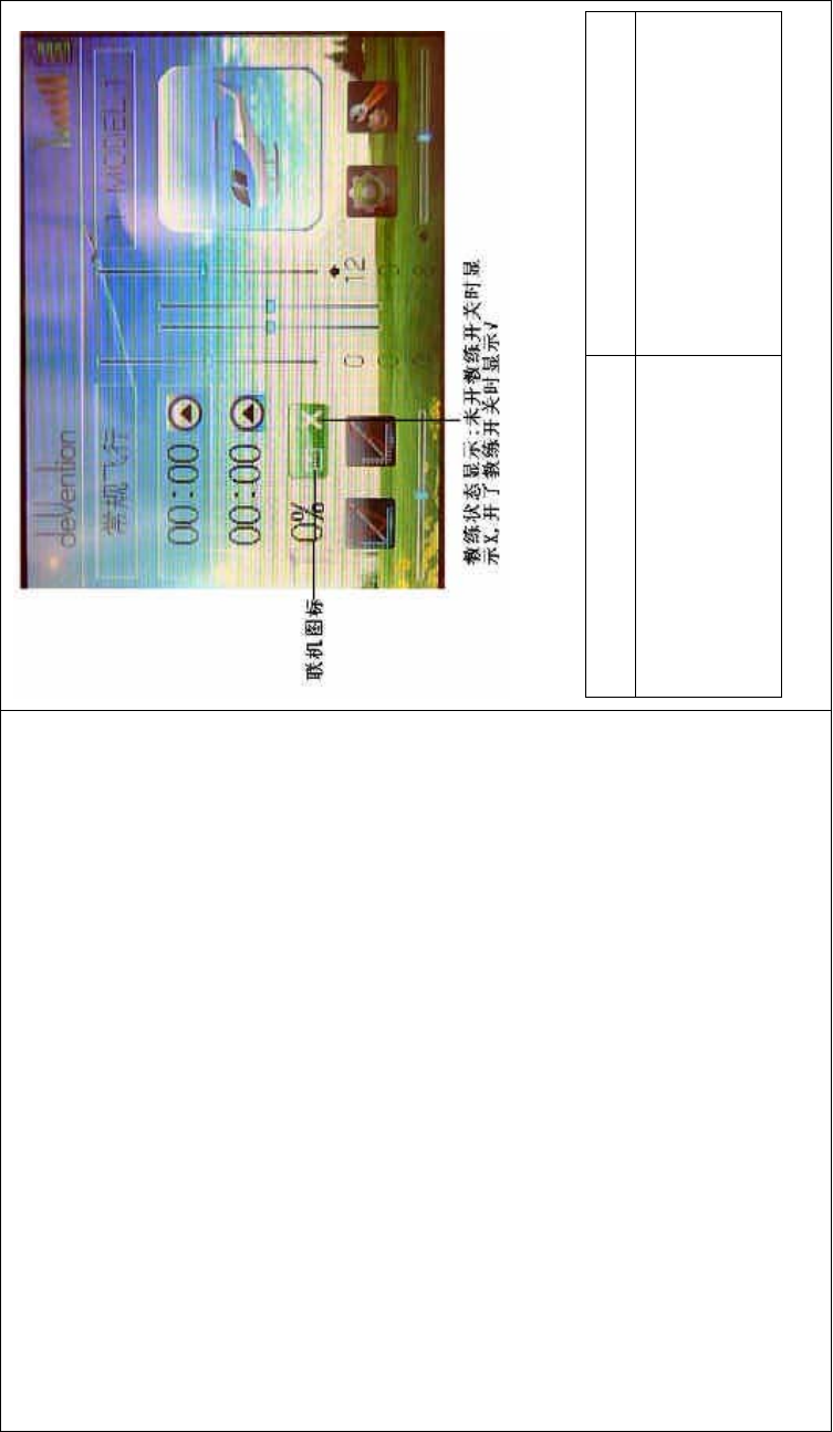
Insert the other end of the digital signal wire into the trainer’s DEVO-8,
and then turn on its power. A linkage icon will be shown as below:
DEVO-8 Page no. Page 33 of 363
㘨ᴎᷛ Linkage icon
ᬭ㒗⢊ᗕᰒ⼎˖ᓔᬭ㒗ᓔ݇ᯊᰒ
⼎Xˈᓔњᬭ㒗ᓔ݇ᯊᰒ⼎Ĝ
Training status: “X” will be shown
when the training switch is turned
RIIDQG³¥´VKRZQZKHQWKH
trai ni ng switc h on.
DEVO-8 Page no. Page 34 of 363
Training status display: when the trainer’s icon becomes into “X”, the
trai nee stops flying and t he trainer is worki ng; when the trai ner’s icon
turns into ĀĜ”, the trainee is flying and the trainer is in leisure.
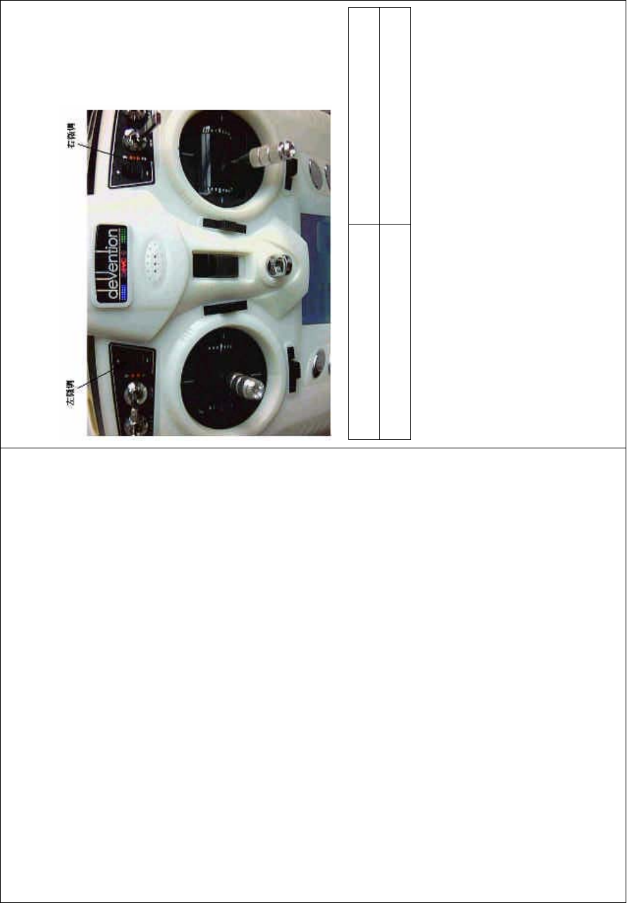
3) Usage method
DEVO-8 Page no. Page 35 of 363
The training switch can be freely switchable between Left trim and Right
trim. The default setting is Right trim. Shown as below:
Ꮊᖂ䇗 Left trim
েᖂ䇗 Right trim
During flight, if the trainer pushes Right Trim once, the lingkage icon will
be shown as ĀĜ” that means the control right is moved to the trainee
from Trainer. If trainer pushes Right Trim once again, the linkage icon
will be shown as “X” that means the trainer takes back the control right
from the trainee.
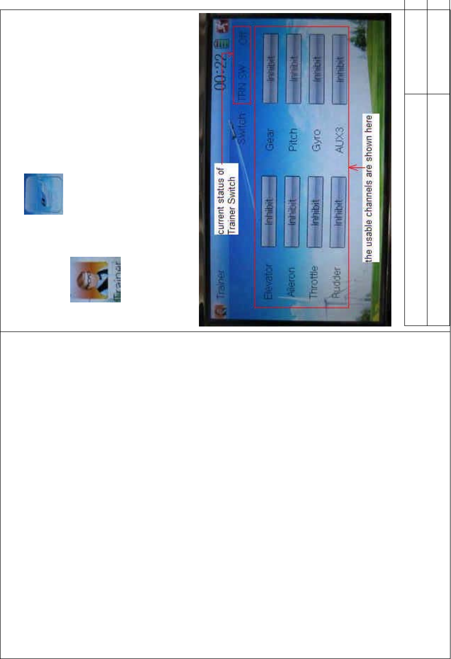
4) Setting for training f unction c hannels
Trainee is available to get full or part of flight control power to the
aircraft model via setting the training function channel in the trainer’s
DEVO-8 Page no. Page 36 of 363
DEVO-8. Below is the setting method:
To uc h t he s ho r tc ut ico n to enter Function Menu, and then
click to get access to Trainer screen.
The available channels are shown below, and the current status of
trainer switch TRN is also shown there.
English Your language
Current status of Trainer Switch (TRN SW)

DEVO-8 Page no. Page 37 of 363
The usable channels are shown here
Touch the channel(s) which you want to grant to trainee. The channel(s)
you have touched will be activated as “Active”. The channels which are
not granted to trainee will be kept inhibited. The default setting is
“Inhibit”.
To uc h to exit.
10.0 Customized fixed ID
This setting will bind DEVO-8 with its receiver in a unique
corresponding relationship. It will greatly speed up the time of automatic
binding when DEVO-8 powered on.
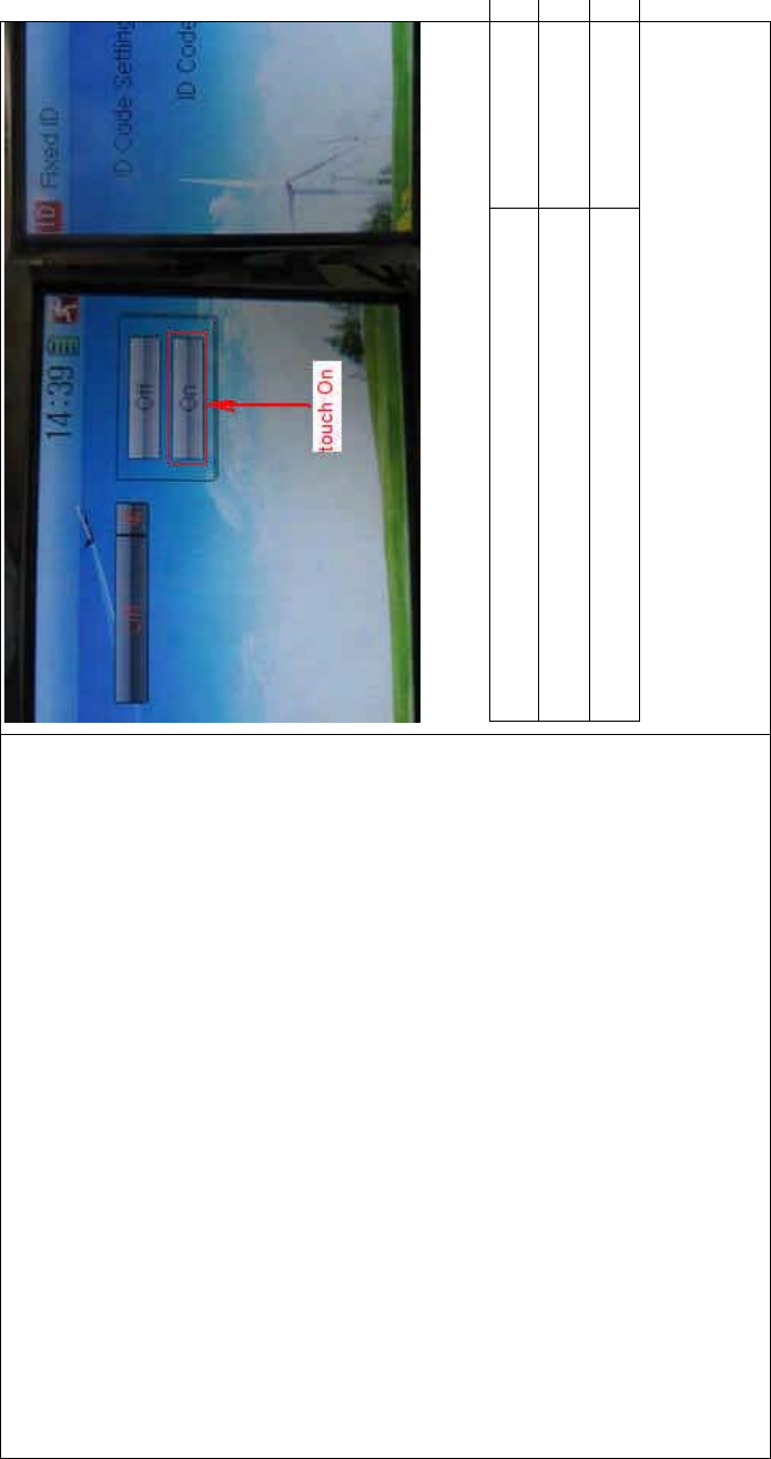
1) Setting for fixed ID
The setting for fixed ID should be under the status that automatic ID
binding is successfully finished. Below is the setting method.
Touch the ico n to enter Model Menu, and then enter Fixed ID by
touchi ng the icon in Model Menu.

DEVO-8 Page no. Page 38 of 363
English Your language
Navigation mark
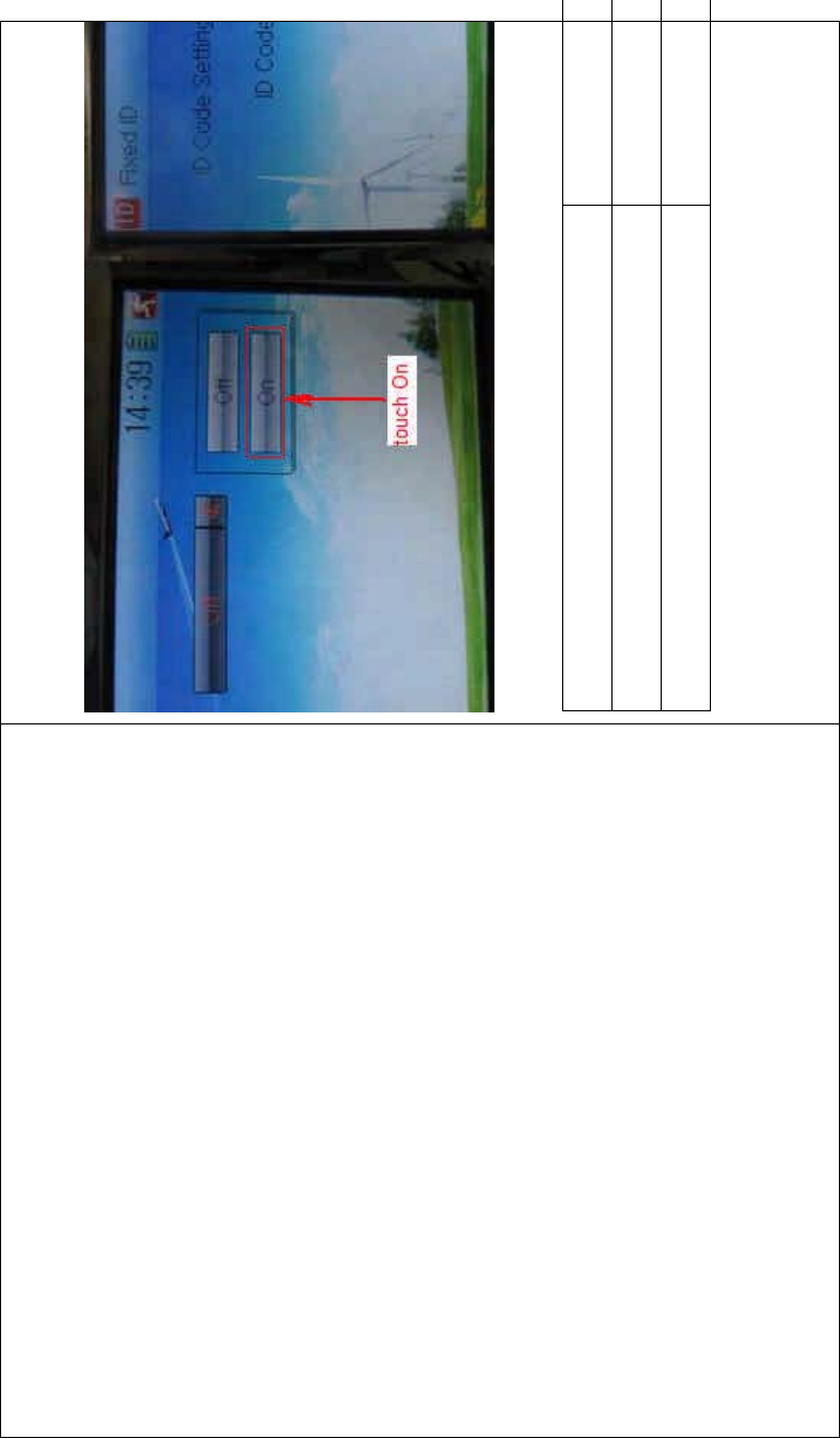
Touch the navigation mark of the item ID Code Setting. It will expand
into two statuses: Off and On. A series of random digits will be shown
below after touching On.
DEVO-8 Page no. Page 39 of 363
English Your language
To uc h “O n”
A series of random digits is shown here
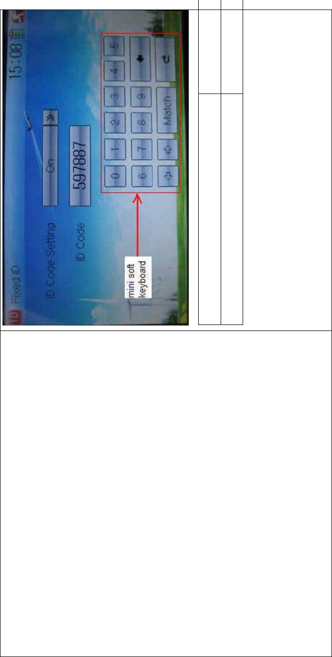
A mini soft keyboard is shown in t he lower part after touc hi ng the
random digits of ID Code
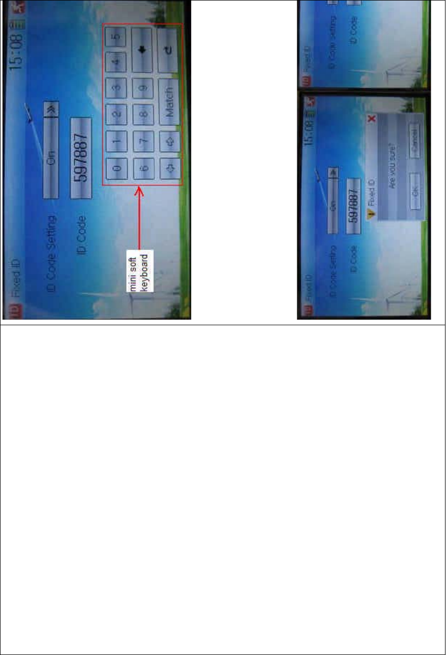
DEVO-8 Page no. Page 40 of 363
The new ID digits can be modified by touching the mini soft keyboard.
Touch Match after the new ID has been set. An INQUIRY interface of
“Are you sure?” pop up. “ID Code Match … …” will be shown after
touchi ng OK.
DEVO-8 Page no. Page 41 of 363
English Your language
ID Code Setting
ID Code
Fixed ID
Are you sure?
Cancelled CANCEL
ID Code Match
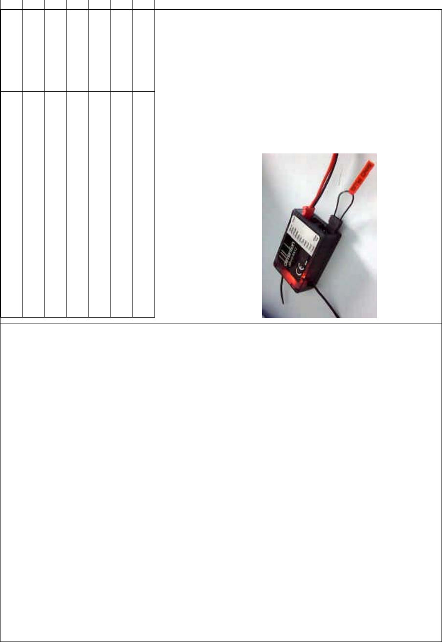
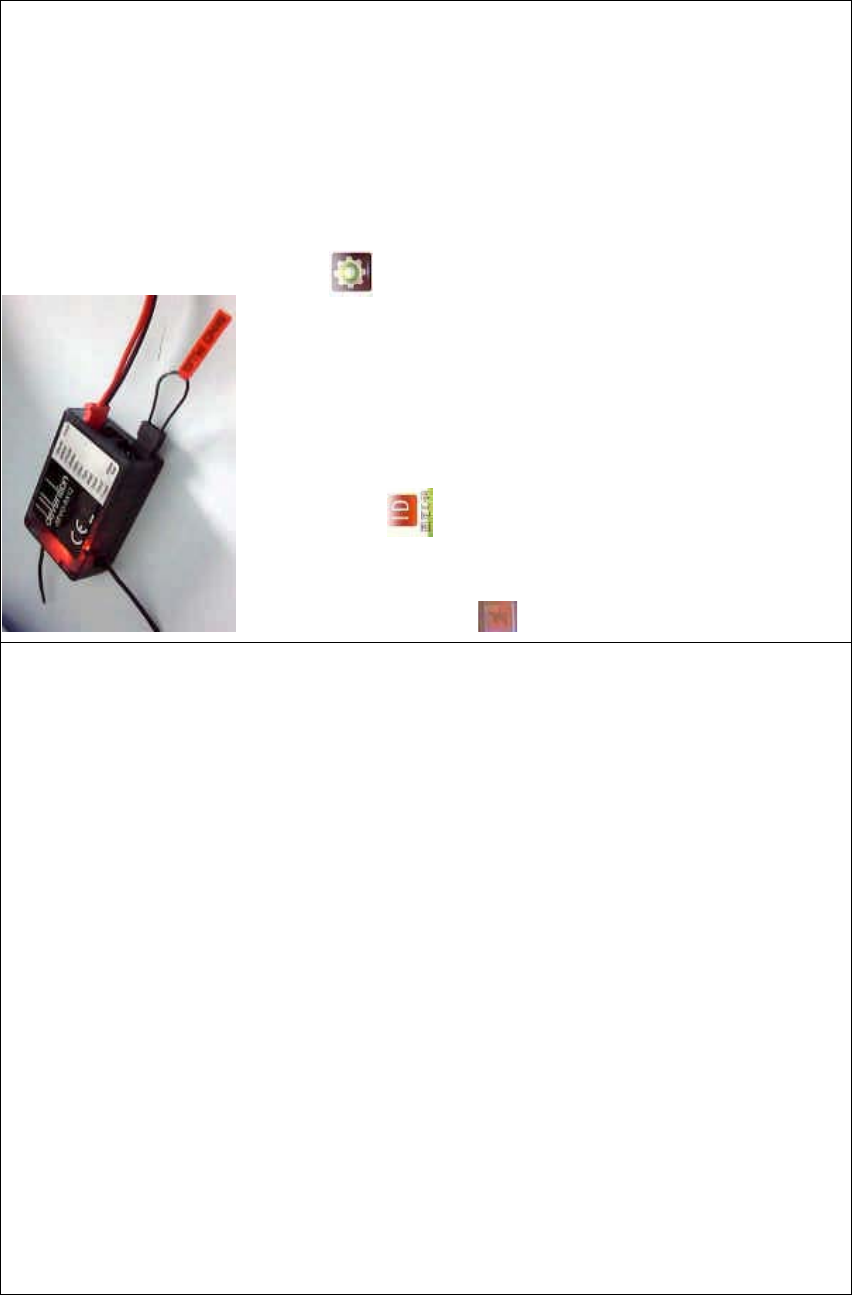
2) Fixed ID cancellation
Insert the assorted BIND PLUG into the output terminal of BATT before
the receiver is powered on, and then plug 5V DC power into other
output terminal. The red light of receiver will flash slowly. This means
the fixed ID code has been cancelled. Pull out BIND PLUG.
DEVO-8 also needs to make relative cancellation and REVISION after
the fixed ID in receiver is cleared out.

DEVO-8 Page no. Page 42 of 363
In the mai n interface touch the icon to enter Model Menu and
then touch to enter Fixed ID. Touch ID Code Setting to expand
the navigation mark into STATUS On and Off. Touch Off. Then touch
to exit.
11.0 Installation requirement for receiver
It is important to correctly mount your remote control system in your
model. Below are some advices on how to install your equipments.
1) Wrap the receiver with 10mm thick foam and soundly fix it with a
rubber or magic string on your aircraft model. It helps protect the
receiver from damage.
2) It is necessary to use rubber grommets and copper sleeves to
isolate the vibrations from the main body of aircraft model. The
mounting screws cannot be over-tightened. Otherwise the rubber
grommets will be distorted and decrease the vibration absorption
effect.
3) When mounting the servos, make sure the servos’ bellcranks can
move freely over their whole travel range and ensure the control
linkages don’t touch or impede the movement of these servos.
4) If installing various switches, keep them far away from the engine
tuned pipe and high vibration sources. Ensure all the switches
move freely over their whole travel range.
5) Don’t make the receiver antennas wrapped or parallel.
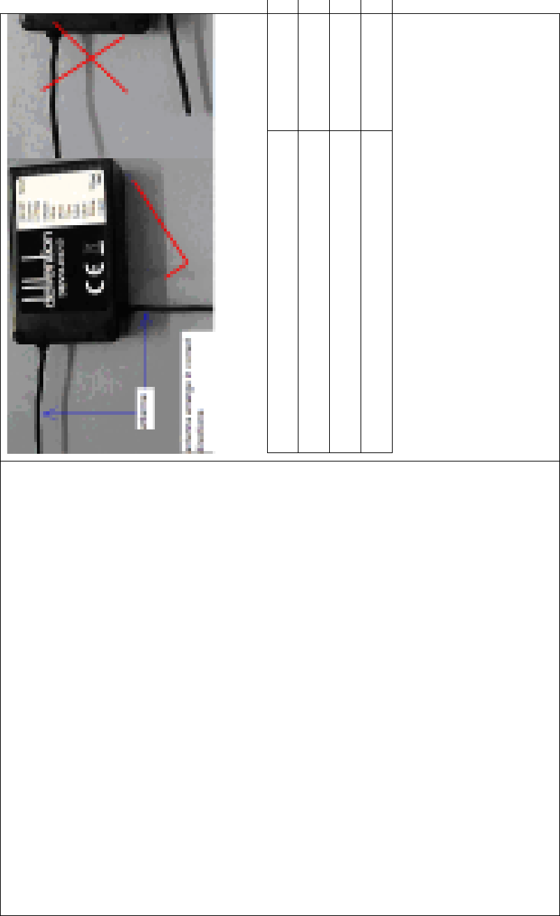
DEVO-8 Page no. Page 43 of 363
English Your language
Antenna
Antenna arranges in correct directions
A
NTENNA IN COR
R
Antenna arranges in wrong directions
A
NTENNA IN WRO
N
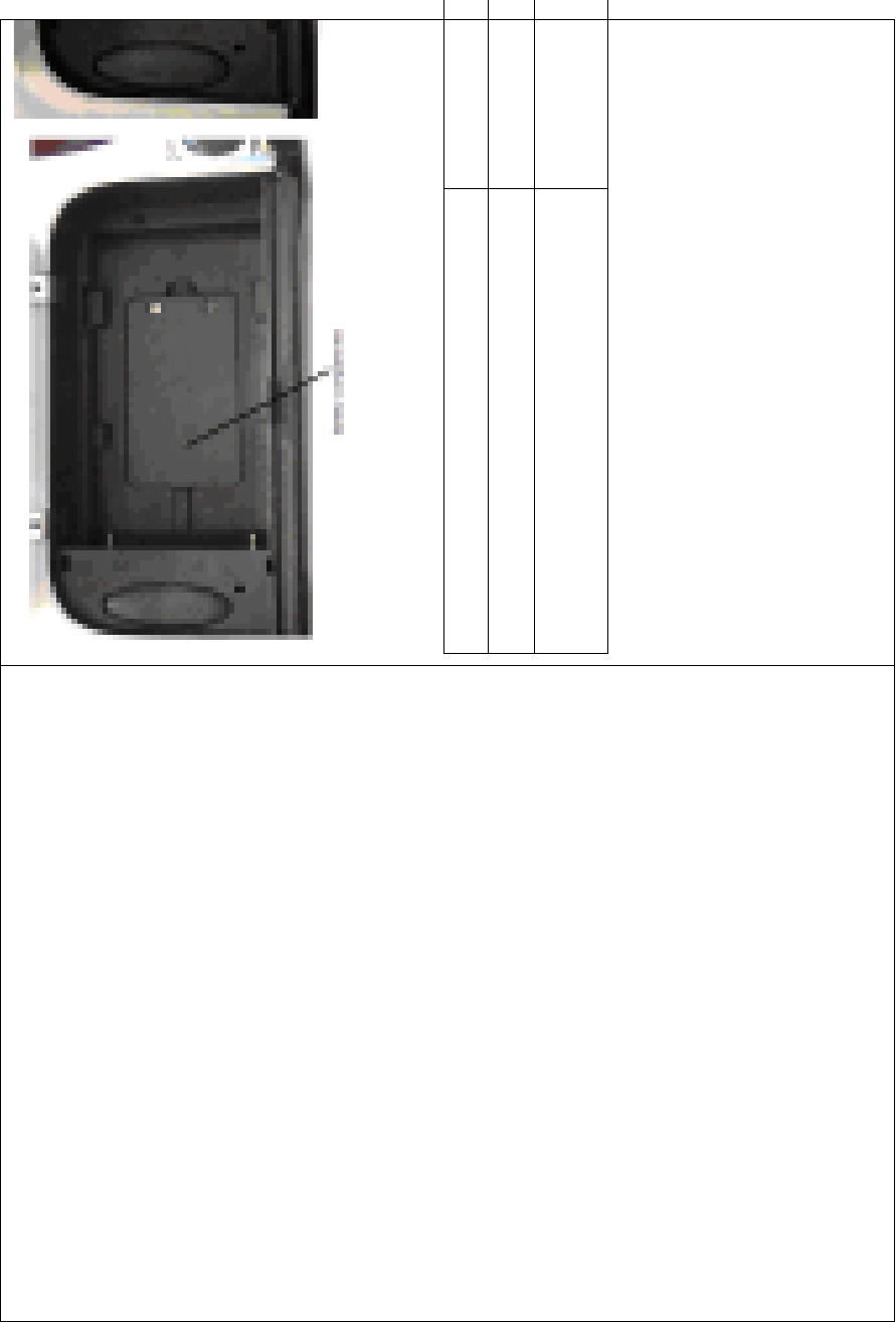
12.0 Installation requirement for DEVO-8
Battery pack
Put the battery pack into the battery compartment in a correct position
and then push it leftwards.
DEVO-8 Page no. Page 44 of 363
English Your language
Battery compartment
Put the battery pack into the battery compartment
and push it leftwards
PUT THE BATTER
Y
COMPARTMENT A
N
12.1 Matters needing attention on battery pack
1) DO NOT disassemble battery pack UNDER ANY
CIRCUMSTANCE
2) DO NOT use or STORE battery pack under high temperature
SUCH as fire, heat, strong sunshine, or car. Otherwise superheat,
fire, functional decline or lifetime dumping may happen.
DEVO-8 Page no. Page 45 of 363
3) DO NOT SUBMERGE the battery pack in water.
4) DO NOT make a short circuit between anode and cathode of
battery pack.
5) DO NOT use damaged battery pack. The battery pack with
electrolyte leaking or smelling should be KEPT AWAY from fire in
order to avoid firing or explosion. IN CASE OF EXPOSURE
TO SKIN, EYES, OR OTHER BODY PART WASH WITH
WATER AND IMMEDIATLY SEEK MEDICAL
ATTENTION.
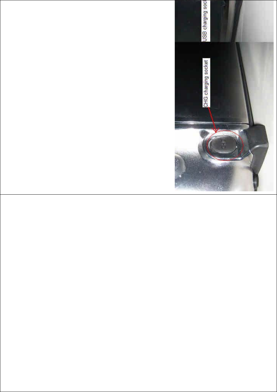
12.2 DEVO-8 battery charging
DEVO-8, which is equipped with two build-in charging circuits, is
powered by 3.7V 3000mAh Lithium Polymer battery. It begins to charge
when the output pin of the assorted power adapter is inserted into CHG
socket, or the normal end of USB connecting line is connected to the
computer USB interface, and the mi ni end is inserted i nto USB in the
side face of DEVO.
DEVO-8 Page no. Page 46 of 363
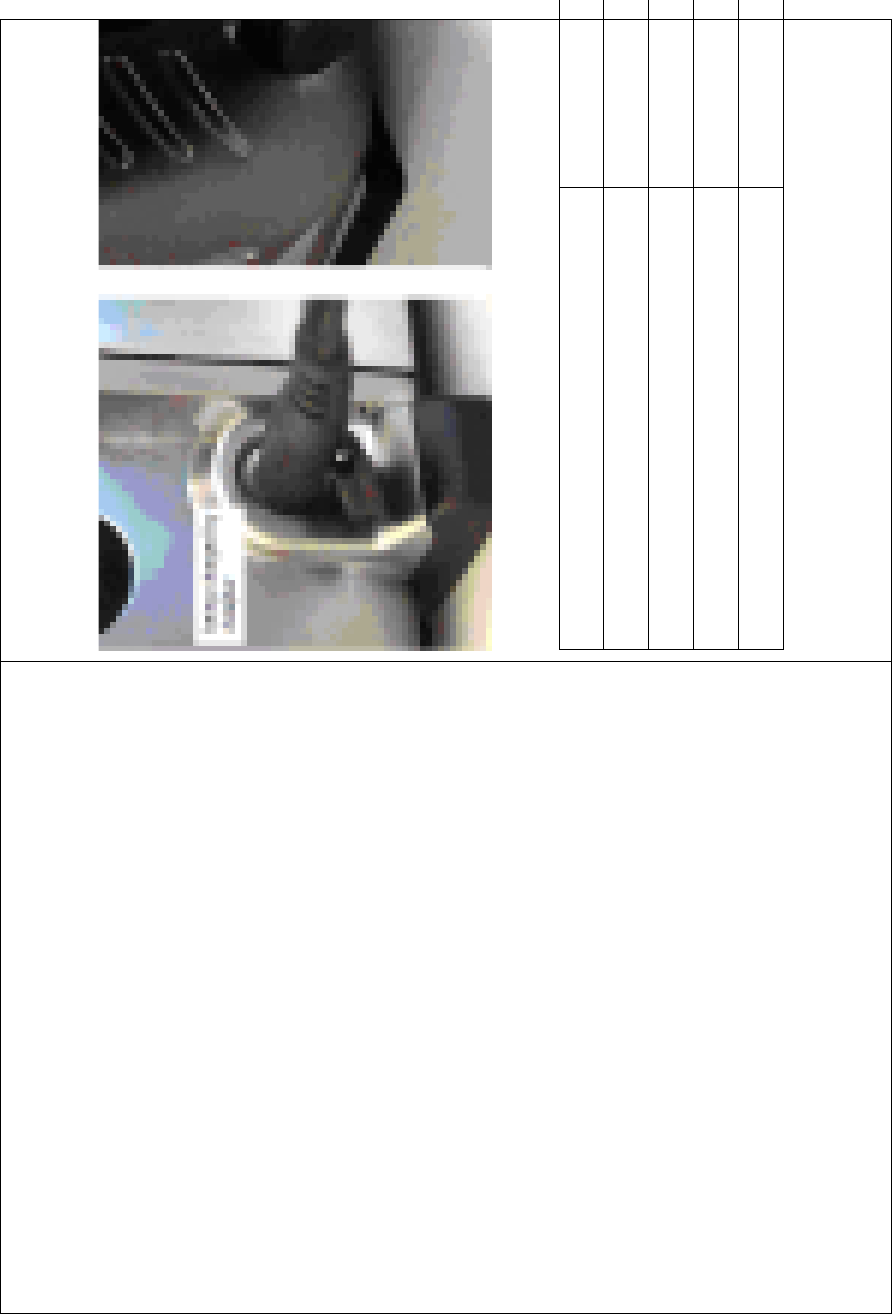
Charging connection is shown as below:
English Your language
CHG charging socket
USB charging socket
Being charged by adapter
Being charged by mini USB
12.3 Voltage parameters

DEVO-8 Page no. Page 47 of 363
Output of assorted power adapter ……………….. 5.0V 2000mA
Maximum current of CHG socket …………………700mA
Maximum current of USB interface ……………….350mA
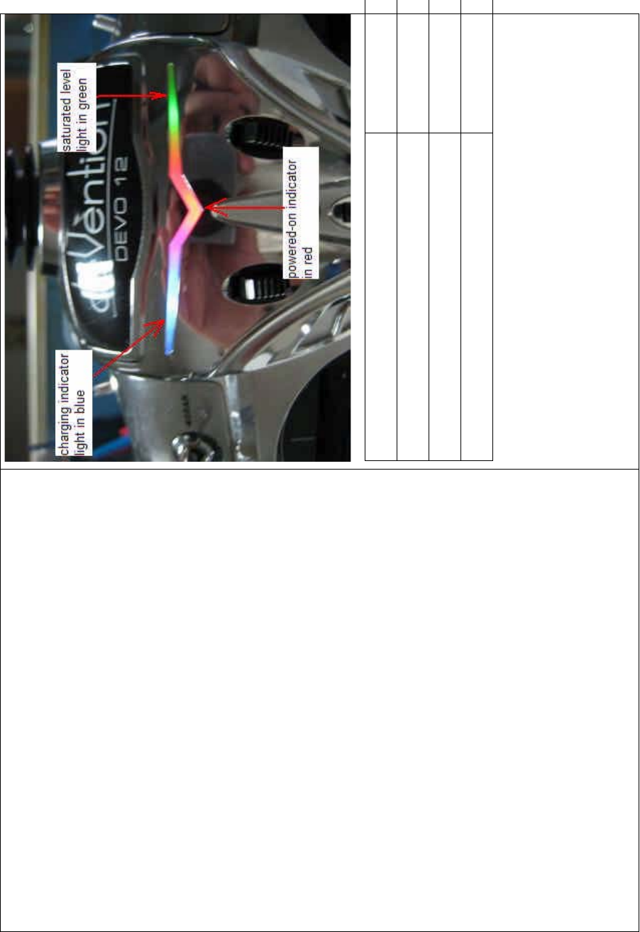
12.4 Indication for charging status
There is a slim V-shape indicator light at the top center of DEVO-8. It
indicates three different working statuses from left to right:
1) Basic status
1.1) Charging indicator light: blue light is ON
1.2) Power-on status of DEVO-8: red light is ON
1.3) Saturation level of charge: green light is lighting when the battery
pack is unsaturated; green light is extinguished when saturated.
DEVO-8 Page no. Page 48 of 363
English Your language
Charging indicator light in blue
Power-on indicator light in red
Saturation level light in green
2) Charging at power-on status:
2.1) Charging indicator light: blue light is always lighting;
2.2) Power-on indicator light: red light is always lighting;
2.3) Saturation level indicator light: the green light is always lighting if

DEVO-8 Page no. Page 49 of 363
the battery pack is unsaturated; the green light is extinguished if
saturated.
3) Charging at power-off status:
3.1) Charging indicator light: blue light is always lighting;
3.2) Power-on indicator light: red light is extinguished;
3.3) Saturation level indicator light: the green light is lighting when
the battery pack is unsaturated; green light is extinguished when
saturated.
Part two: Helicopter
1.0 System menu
All the functional settings, which are relative to the operation system of
DEVO-8 itself, are FULLY integrated in System Menu. They include
Language, Skin, Display, Buzzer, Date & Time, TFT Screen, Stick
Mode, Stick & LeverˈPower Amplifier, and About.
Below is the boot screen of helicopter:
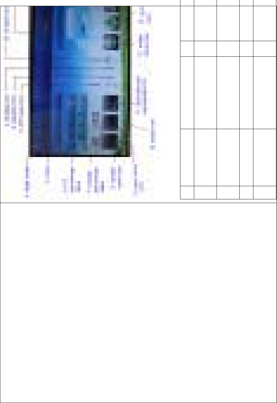
DEVO-8 Page no. Page 50 of 363
English Your language English
1 Throttle trim 11 Dual rate
exponential
2 Elevator trim 12 Model m
e
icon
3PIThovertrim 13G
yro sensor ic
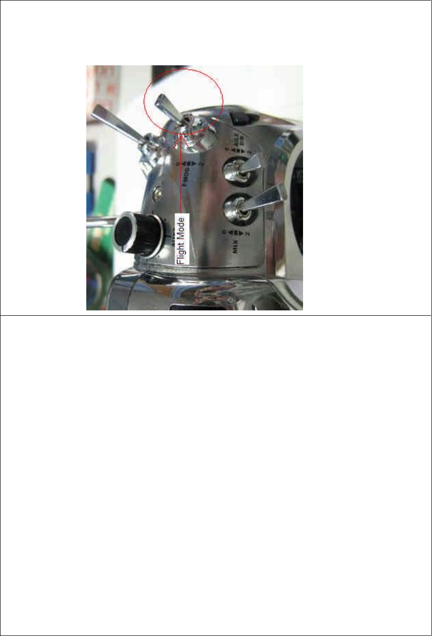
4 Flight mode 14 System m
e
icon
DEVO-8 Page no. Page 51 of 363
5 Timer 15 Function m
e
icon
6 PIT percentage
value
16 Model name
7 Throttle
percentage value
17 Battery volu
m
display
8 Throttlecurveicon 18 Timedisplay
9 Pitch curve icon 19 Transmission
power display
10 Rudder trim 20 Throttle ho
v
trim
1.1 Language setting
Touch the s hortcut icon to enter System Menu and then touch
to enter the LANGUAGE INTERFACE.Touch the language
that you want to select. A ĀĜ”willbeshownonthescreenafter
selected.

DEVO-8 Page no. Page 52 of 363
Then touch to save and exit.
1.2 Skin selection
DEVO-8 offers three skins for your selection.
Touch to enter System Menu and touch to enter Skin.
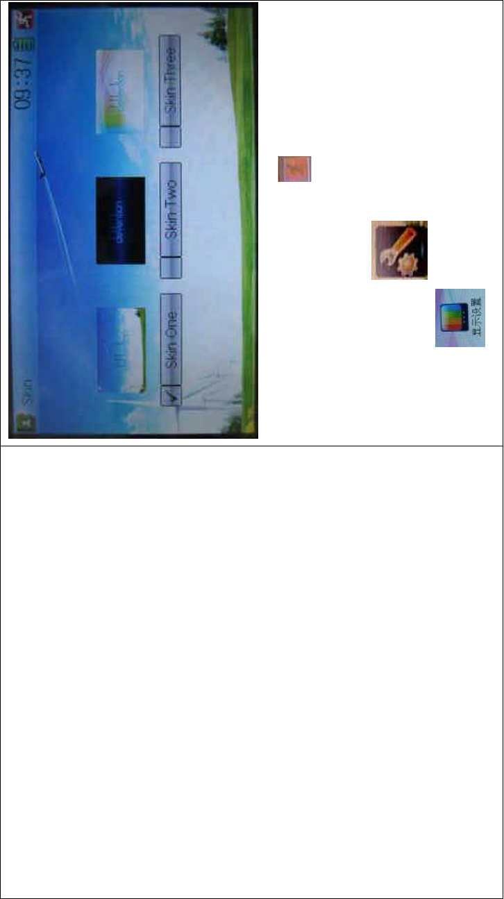
DEVO-8 Page no. Page 53 of 363
Touch the skin yo u desire and then touch to exit.
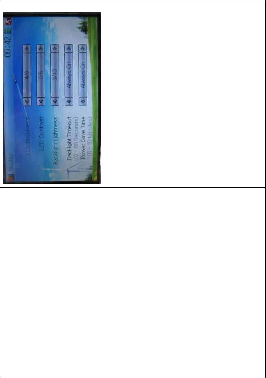
1.3 Display
Touch the shortcut icon to enter System Menu and then
touch the icon to enter “Display”.
DEVO-8 Page no. Page 54 of 363
Five items are available to be set. Below are the setting methods for
them:
1) LCD brightness: it is possible to increase or decrease the LCD
brightness by touching the navigation marks. The power
consumption will be increased if the LCD is too bright and the
battery cruise duration will also be shortened.
2) LCD contrast: the contrast is adjustable by touching the navigation
marks. The power consumption will be increased if the contrast is
too high and the battery cruise duration will be shortened.
3) Backlight lightness: the backlight lightness is adjustable by touching
the navigation marks. The power consumption will be increased if
the backlight lightness is too bright and the battery cruise duration
will be shortened.
4) Backlight time out: it is possible to set the duration which LCD stays
at highlight in the form of “Always on” or any period from 5 to 60
seconds with an interval of 5 seconds.
DEVO-8 Page no. Page 55 of 363
5) Power save time: it can adjust the backlighting duration by turning
off the backlight in order to prolong the battery cruise time. The
setting status contents Always On and duration in 30 grades with an
interval of 1 minute.
6) Touch to exit.
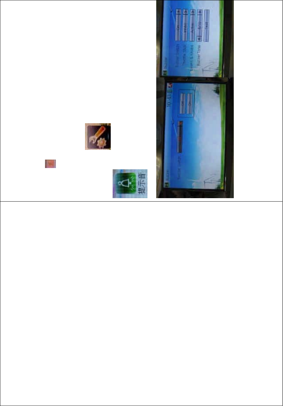
1.4 Buzzer warning
To uc h t he i co n to enter System Menu and then touch
to enter the BUZZER INTERFACE.
1) Buzzer switch: to uch the navigation mark at Buzzer Switc h and pop
up an alternative item: Off and On. If touching On, a drop-down
menu will be shown below.
2) Throttle stick buzzer: under Buzzer Switch is at the status of On, if

DEVO-8 Page no. Page 56 of 363
Throttle Stick is set as “Active”, a relative musical scale will make
response when moving the throttle stick. You can judge the position
of the throttle stick according to the different musical scales. Also, it
can be set as Inhibit.
3) Levers and knobs buzzer: under the condition that this item is set as
“Active”, DEVO-8 will sound when rotating or moving such levers or
knobs as AUX2, AUX3, AUX4, AUX5, AUX6, and AUX7 to their
neutral positions. It can also be set as “Inhibit” to silence the
musical scales.
4) Buzzer tone: the tone is composed of 10 grades. You can choose
the favorite one according to your interests. Touch Test to make a
listening test.
To uc h to exit after finished.
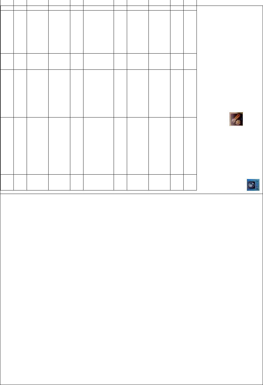
1.5 Date & Time
To uc h t he i co n to enter System Menu and then touch
to enter the item of “Date & Time”.

DEVO-8 Page no. Page 57 of 363
The clock setting is grouped into Year, Month, Day, and Time. Touch the
navigation marks, respectively, to make modifications.
To uc h to save and exit.
Note: if incorrect turn-on or production time appears, one possibility is
that the power supply for the clock is not enough. Replacing a new
button cell is a must.
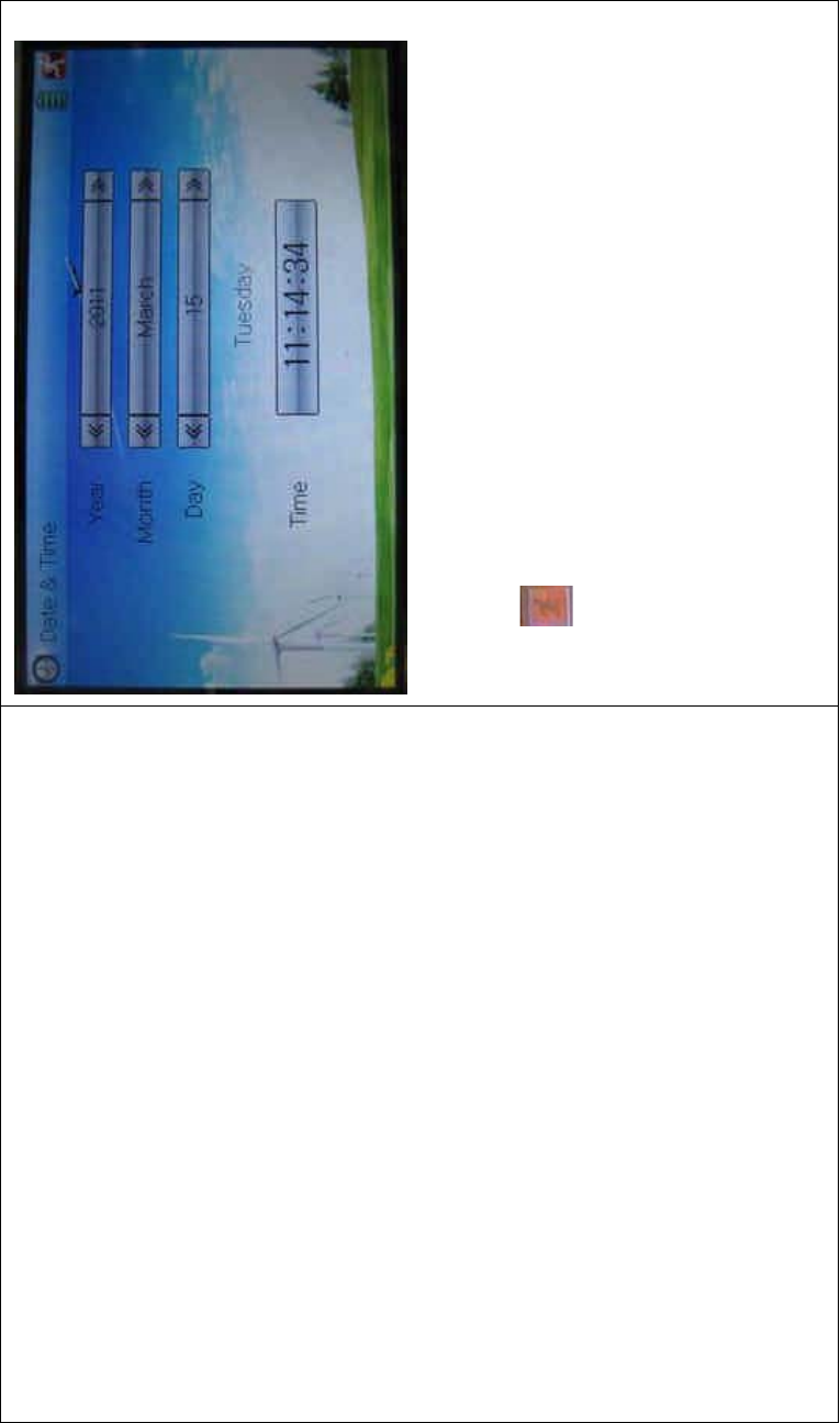
The method for changing button cell:
Turn off the power of your DEVO-8 and take out its battery pack. Use a
cross screwdriver to remove the two fixing screws on the fixing board.
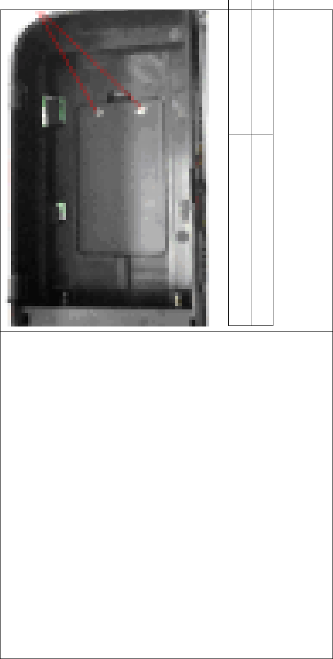
DEVO-8 Page no. Page 58 of 363
English Your language
Fixing screws
Push outwards the button cell holder, and the button cell will
automatically pop up. Replace the old cell with a new one.
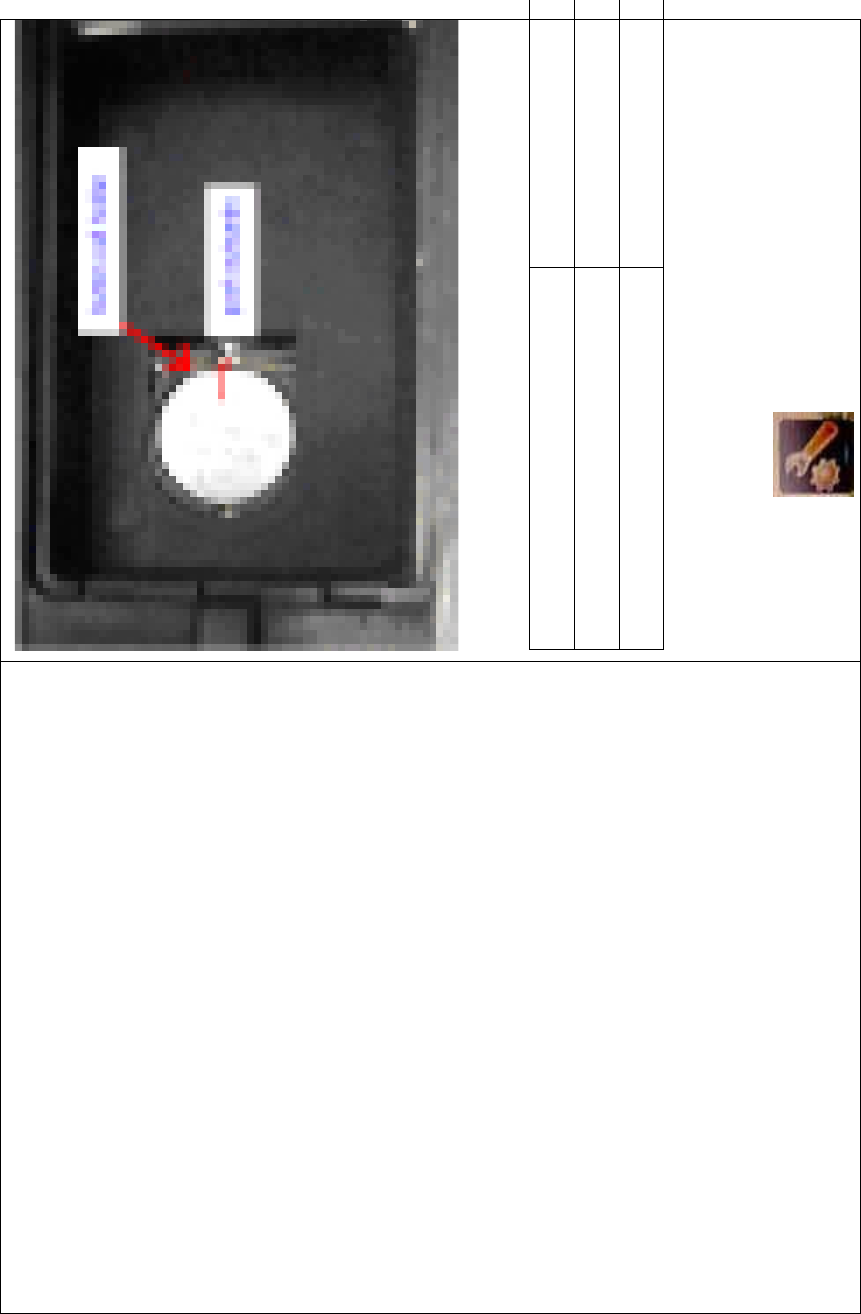
DEVO-8 Page no. Page 59 of 363
Cell size: CR 1220 3V
English Your language
Button cell holder
Push outwards
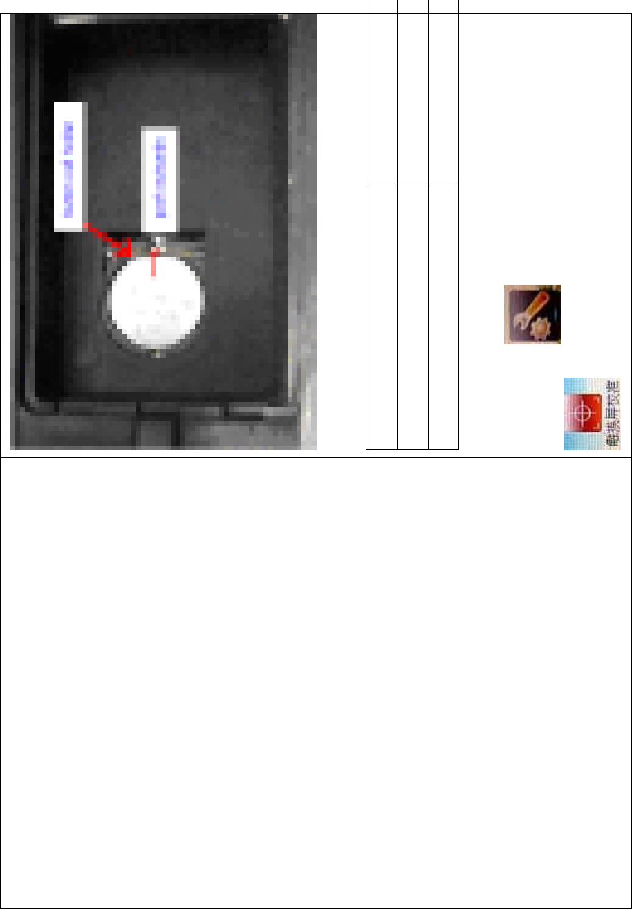
1.6 TFT screen calibration
To uc h t he i co n to enter System Menu and then touch

DEVO-8 Page no. Page 60 of 363
to enter the TFT SCREEN CALIBRATION
INTERFACE.
Click anywhere on the screen to start calibration with the touch pen,
and then follow the indication to calibrate. It will automatically return to
System Menu after the calibration is finished.
1.7 Stick mode
Touch the icon to enter System Menu, and then touch the
icon to enter the STICK MODE INTERFACE.

DEVO-8 Page no. Page 61 of 363
There are four stick modes from MODE 1 to MODE 4. Select the stick
mode you desire and then to uch the icon to exit.
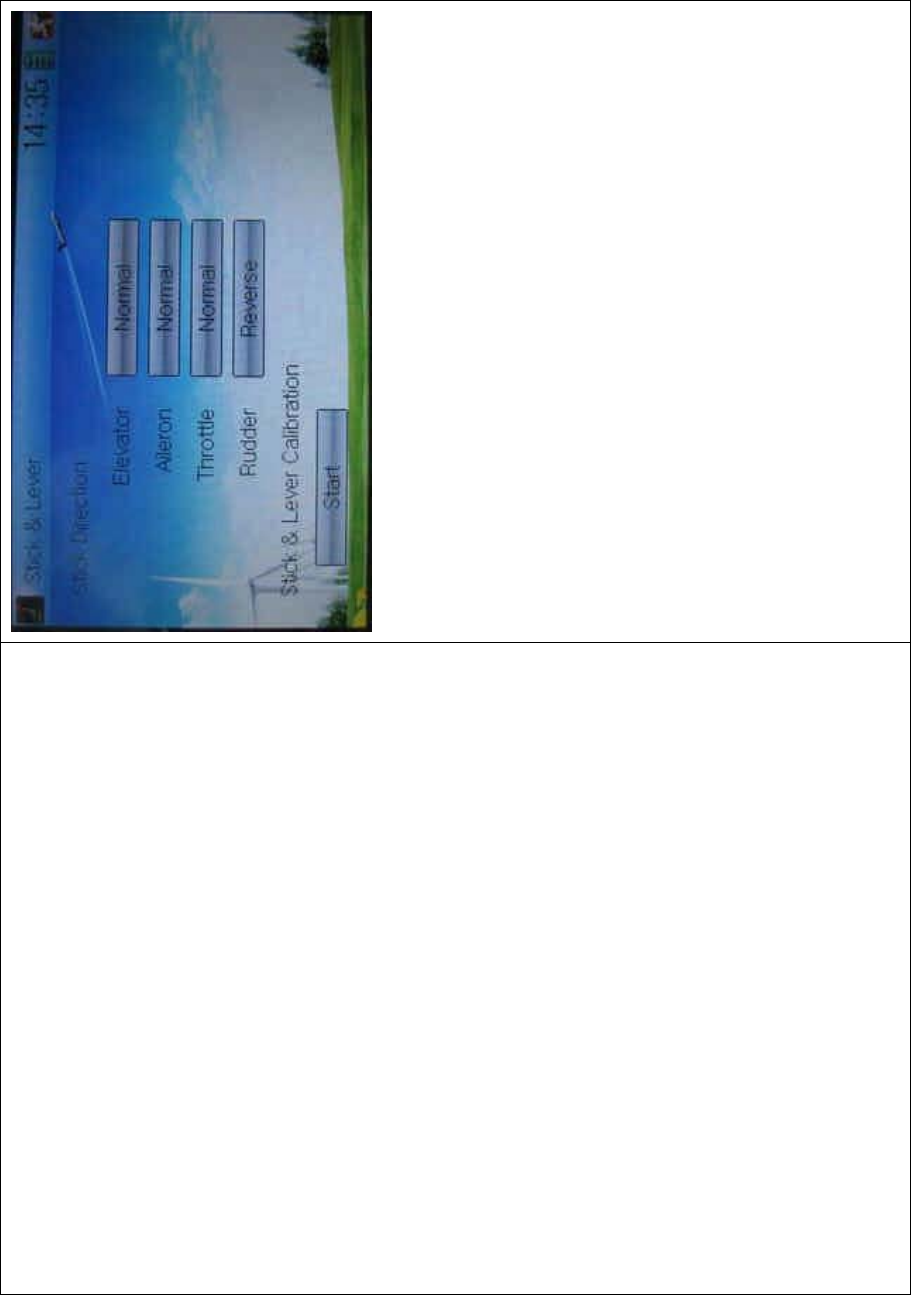
1.8 Stick and lever
To uc h t he ico n to enter System Menu and then touch the
icon to enter the interface of Stick and Lever. There are two
items in the interface: Stick Direction and Stick & Lever Calibration.
DEVO-8 Page no. Page 62 of 363
1) Stick direction: there are four options: Elevator, Aileron, Throttle,
and Rudder. Click the item, which you want to reverse, to change
the output direction of the stick. The default setting is Normal.
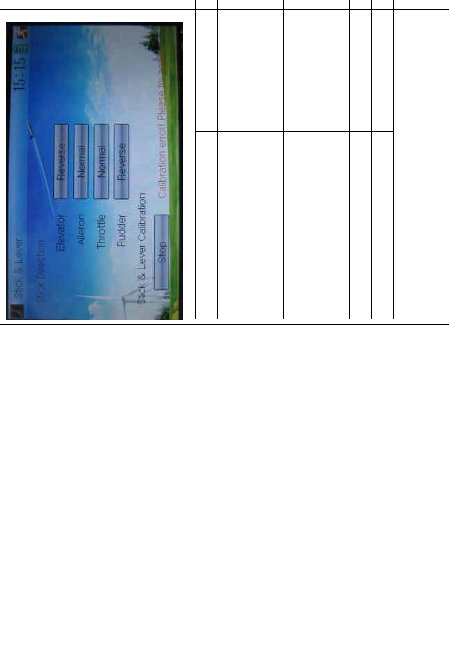
2) Stick & lever calibration: if variance happened in sticks or levers, it
wouldbecalibratedviathisoption.
Method for calibration:
Click the display item of Start to enter the status of calibration, and Start
will be turned into Stop.
2.1) Stick calibration: Clockwise or counter clockwise mechanically
move the right stick and left stick from their mi nimum levels to their
maximum levels several times, and then return the sticks to the neutral
positions, respectively.
2.2) Lever calibration: mechanically move the levers of AUX2, AUX3,
AUX4, and AUX5, respectively, from the minimum level to the maximum
level several times, and then return to the neutral positions,

DEVO-8 Page no. Page 63 of 363
respectively.
2.3) Click the item of Stop. If the calibration is finished, “Calibration
success!” will be shown at the lower of the screen. If the calibration is
failed, “Calibration error! Please try again!” will be shown instead. It
needs to be calibrated again.
DEVO-8 Page no. Page 64 of 363
English Your language
Normal
Reverse
Stick direction
Stick & lever calibration
Start
Stop
Calibration success
Calibration error! Please try again!
2.4) Re-calibration: directly repeat the said steps 2.1 and 2.2 in the
calibration failure interface.
DEVO-8 Page no. Page 65 of 363
Touch the icon to exit.
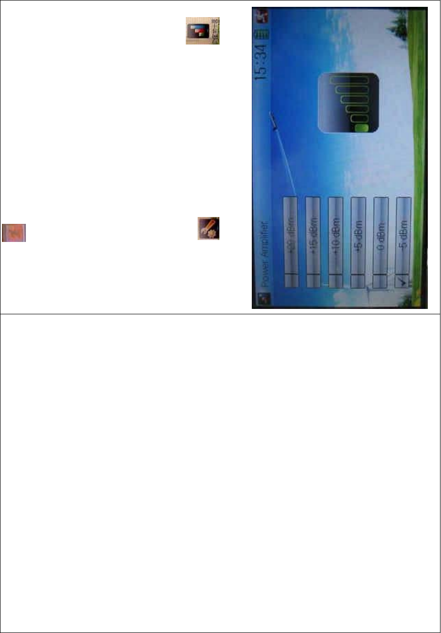
1.9 Power amplifier
The transmission output power of DEVO-8 is adjustable. It is divided
into six grades from small to big. The lower the transmission output
power transmits, the shorter the radio range is, and the longer the
stand-by time will be. The higher the transmission output power, the
farer the radio range, and the shorter the stand-by time. Choose the
appropriate transmission output power according to the actual situation.
Setting method:
To uc h t h e i c o n to enter System Menu and then click to
enter the POWER AMPLIFIER INTERFACE.
DEVO-8 Page no. Page 66 of 363
Choose the appropriate output power level and then touch to exit.
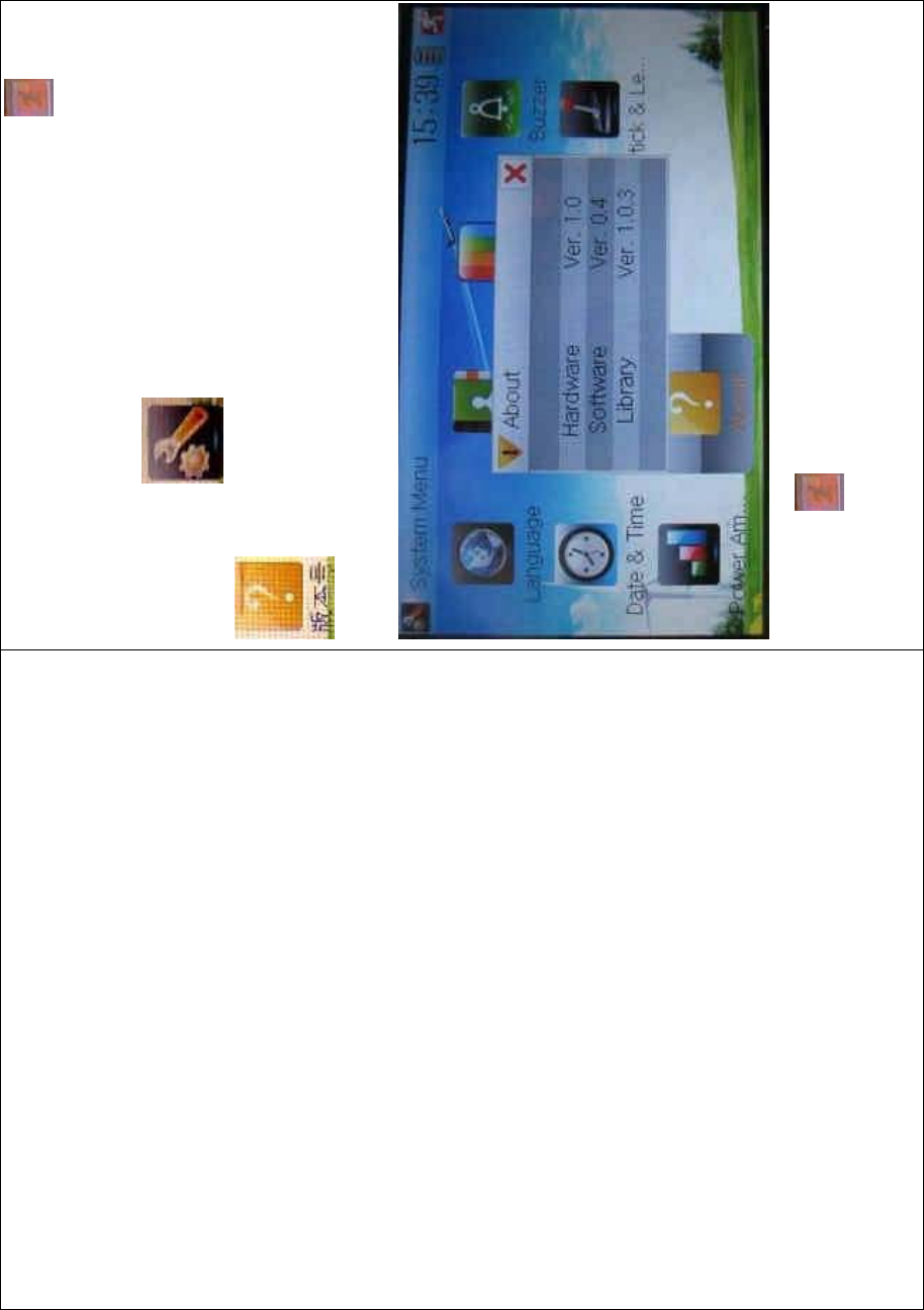
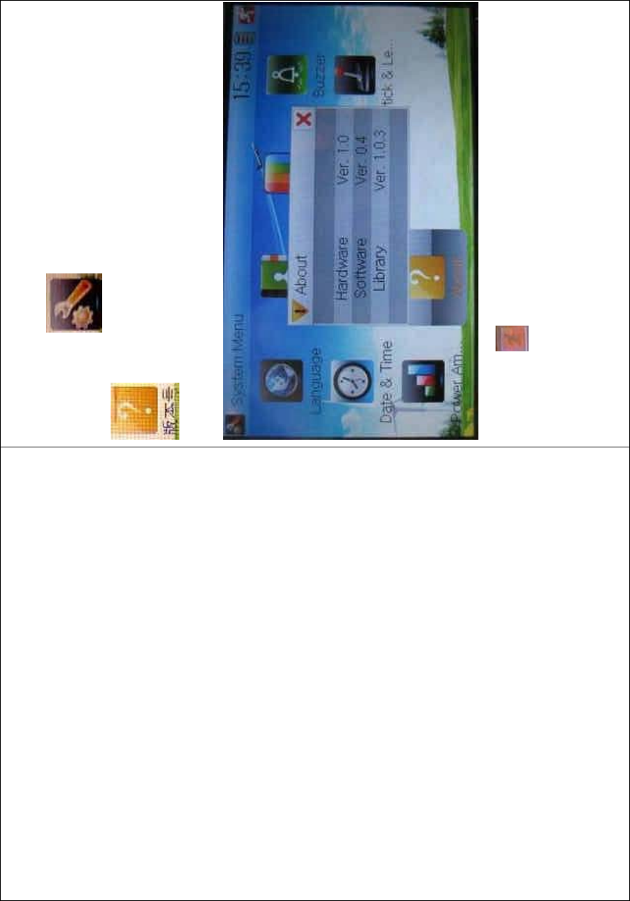
1.10 About
To uc h t he i co n to enter System Menu and then touch
to get access to the ABOUT INTERFACE. You can check
the versions of hardware and software.
Click the icon to exit.
2.0 Model menu
DEVO-8 Page no. Page 67 of 363
Model Menu manages all the model data saved in DEVO-8. It includes
Model Select, Model Name, Model Copy, Model Transmit, Model
Receive, Model Reset, Type Select, Trim System, Stick Position,
Warning, Device Select, Device Output, Swash Type, and Fixed ID.
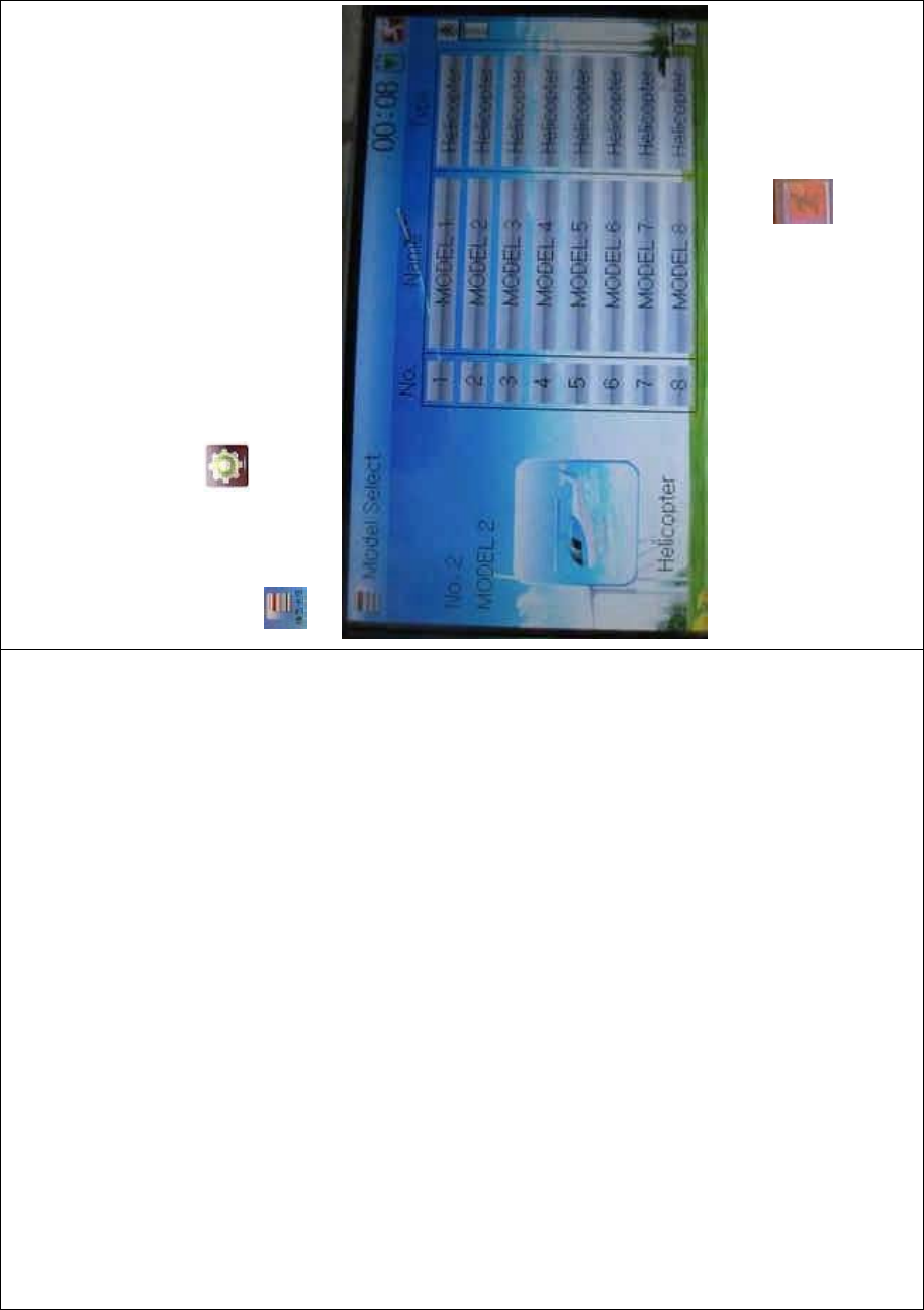
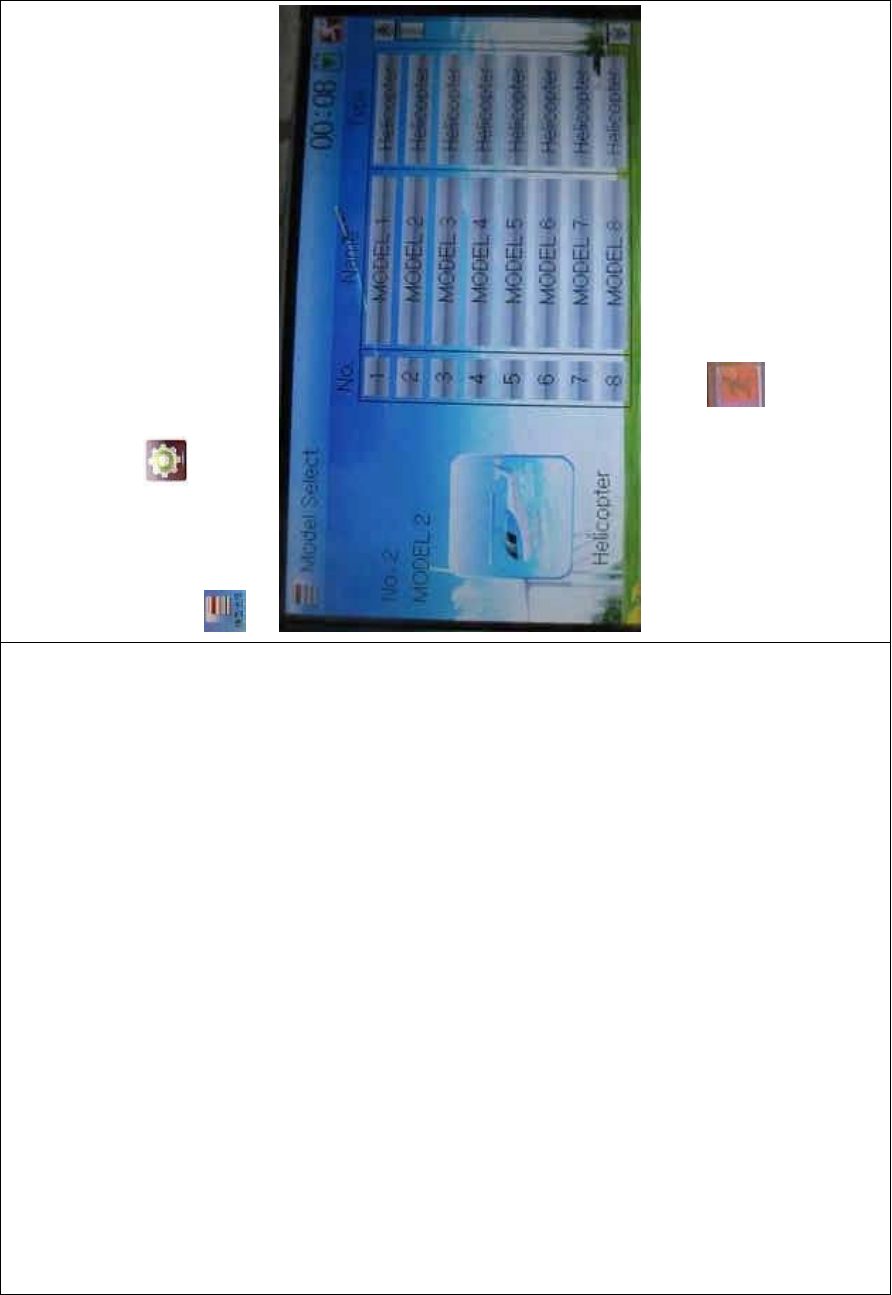
2.1 Model select
Touch the icon to enter Model Menu and then click the icon
to enter the MODEL SELECT INTERFACE.
Click the model you desired. The selected model will be temporarily
changed into orange color. Then click the icon to exit.
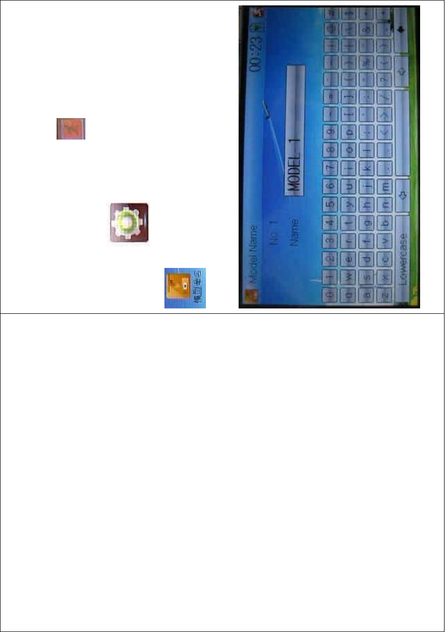
2.2 Model name
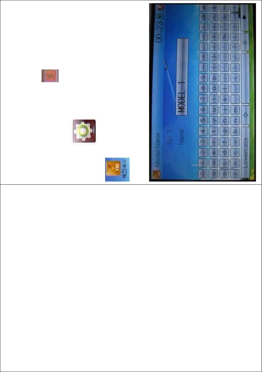
DEVO-8 Page no. Page 68 of 363
In the menu of Model Name, you can make a desired name for your
model for long term storage. Its data can be directly withdrawn in next
flights.
Repeat the step “2.1 Model Select” to choose the model you want to
name or save. And then to uc h the icon to exit.
Click the icon to enter System Menu and then click the icon
to get the MODEL NAME INTERFACE. The following is
the interface:
DEVO-8 Page no. Page 69 of 363
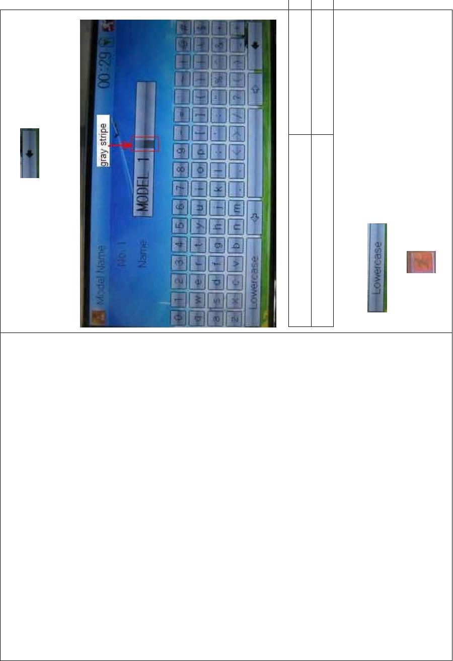
Click the right blank frame of Name and a gray stripe will be shown in
the frame. Touch the return key to clear up the old name.
English Your language
Gray stripe
Touch the soft keyboard to input a new name. It is possible to switch
between lowercase and uppercase by clicking the
key .
Then touch to exit.
DEVO-8 Page no. Page 70 of 363
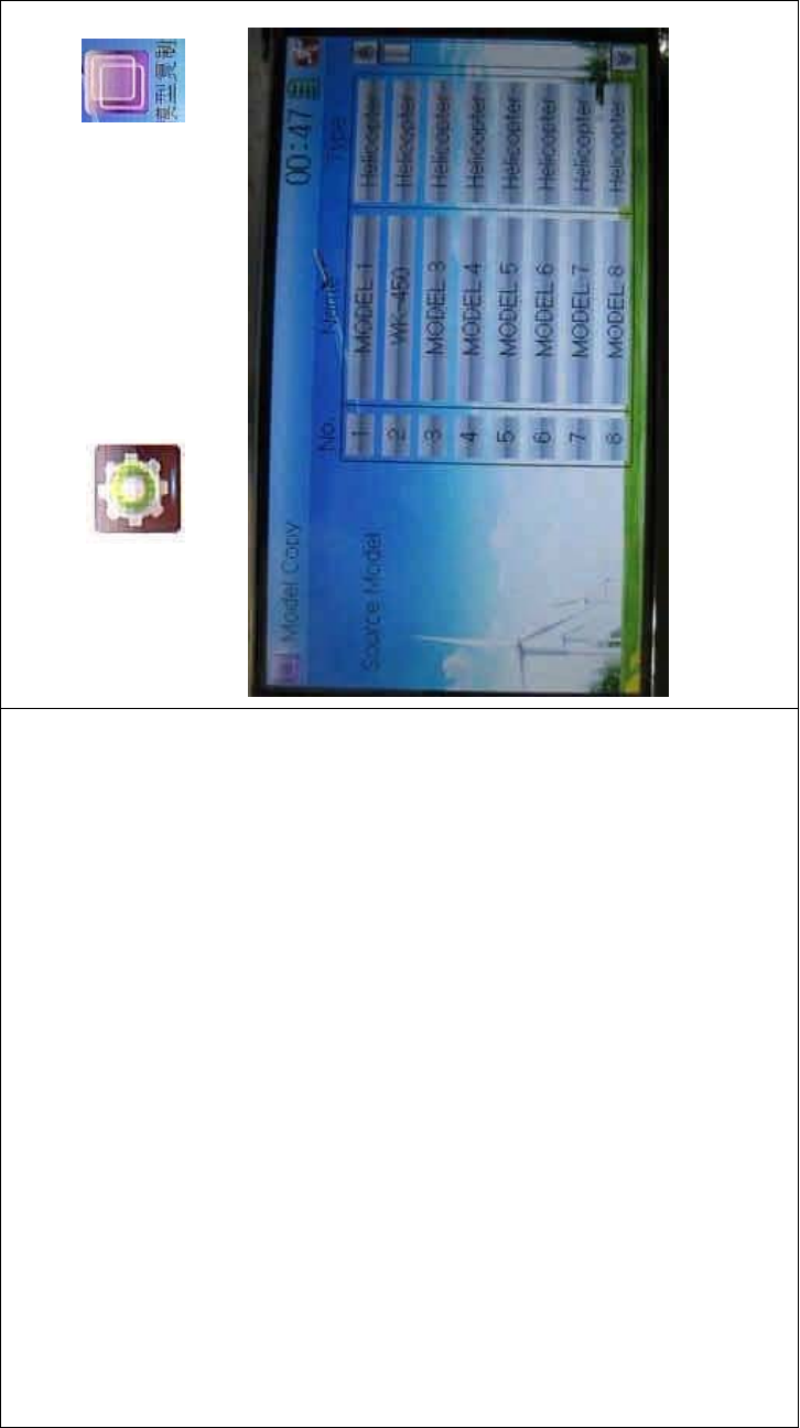
2.3 Model copy
Touch the icon to enter Model Menu and click to
enter Model Copy.
Choose the model you want to be copied as source model. The serial
No. and model name of Source Model will be shown in the left side of
the interface.

DEVO-8 Page no. Page 71 of 363
Then touch the model in the right list where you want to locate the
source model. The serial No. and name of the model you chose are
shown under Dest Model in the lower left of interface as well as an
enquire “Are you sure?” is popped up.

DEVO-8 Page no. Page 72 of 363
Click OK to copy. Otherwise click Cancel. Then the interface will be
automatically returned to Model Menu. Click to save and exit.
2.4 Model wireless copy
The model data between two DEVO-8 equipments can be wirelessly
copied via Model Transmit and Model Receive in Model Menu
1) Model transmission
Touch the icon to enter Model Menu and then continue to click
the icon to enter Model Transmit.

DEVO-8 Page no. Page 73 of 363
Choose the source model which will be transmitted. The serial No. and
name of the source model will be shown under Select Model in left side
of the interface as well as enquiry information “Are you sure?” in the
right side.

DEVO-8 Page no. Page 74 of 363
Click OK for transmission or Cancel for rejection. Enquiry information
“Transmitting ……” appears after clicking OK. Touch the icon to
exit.
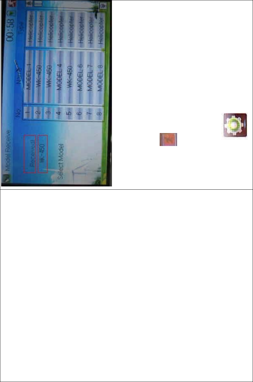
2) Model receiving
Touch the shortcut icon to enter Model Menu and then touch the
icon to enter the MODEL RECEIVE INTERFACE. Enquiry
inf ormation “Are you s ure?” is s hown in the center of the interface.
Click Ok for receiving or Cancel for rejection. “Connecting ……” and
“Receiving ……” will be shown in series in the interface. The
information of “Received” with the model name will be shown in left side
after receiving is finished.
DEVO-8 Page no. Page 75 of 363
Choose the save position in the right name list. Enquiry information “Are
you sure?” is shown after clicking the save position. Click OK for save
and the current interface will automatically return to Mode Menu. Click
Cancel for rejection.
Touch the icon to exit.
2.5 Model reset
All the model data can be restored to factory settings via Model Reset.
Touch the icon to enter Model Menu and then click

DEVO-8 Page no. Page 76 of 363
to enter Model Reset.
It is possible to store up to 60 models data in the model list of DEVO-8
equipment. There are two methods to reset the model data: batch reset
and single reset.
1) Method for batch reset:
Touch ‘All Models’ in Model Reset interface. Then ‘’All Models” and
enquiry “Are you sure?” appear in the left side. Click OK for reset, or
Cancel for rejection.

DEVO-8 Page no. Page 77 of 363
2) Method for single reset:
Touch the upper or lower navigation mark to move the scroll bar, and
then choose the model you want to restore in the model name list. The
selected model’s name, serial No and enquiry “It is in use! Are you
sure?” will appear in the left side. Click OK for resetting, or Cancel for
rejection.

DEVO-8 Page no. Page 78 of 363
Click the icon to exit.
2.6 Type select
This device offers three model types menu. They are helicopter,
airplane, and glider, respectively.
Touch the icon to enter Model Menu and then click
to enter Type Select.

DEVO-8 Page no. Page 79 of 363
Choose the model type and then to uch the ico n to exit.
2.7 Trim system
Trim System is able to finely tune the following six items, respectively:
Elevator, Aileron, Rudder, Throttle, Left Trim, and Right Trim. The trim
range is divided into 20 grades (factory default is set at 4). It is
convenient to subtly modify the pitch by adjusting the trim range.
Touch the icon to enter Model Menu and then click

DEVO-8 Page no. Page 80 of 363
to enter Trim System.
Touch the corresponding navigatio n mark to change the trim value. The
bigger the trim value is, the bigger the trim range will be.
For elevator, aileron, and rudder, there are two more options: Normal
and Limited. “Normal” means the trim is always working although the
corresponding stick stays anywhere. “Limited” means the trim is out of
working when the corresponding stick is at maximum position.
2.8 Stick position
The stick can be used as a switch. The turn-on or turn-off position at
which the stick stays can also be settable.
Method for setting:
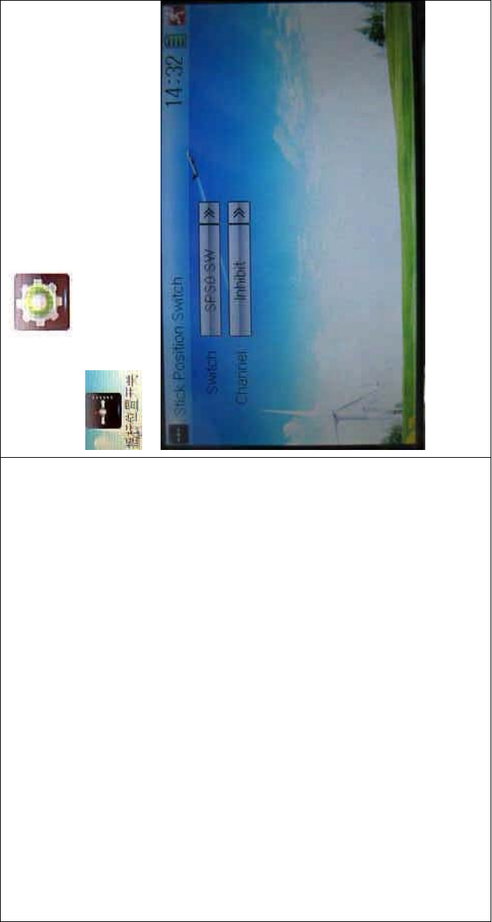
DEVO-8 Page no. Page 81 of 363
Touch the icon to enter Model Menu and then click
to enter Stick Position Switch.
Click the navigation mark of Switch. It pops up a drop-down menu:
SPS0, SPS1, SPS2, and SPS3. Choose the switch you want to define.

DEVO-8 Page no. Page 82 of 363
Then touch the navigation mark of Channel. It expands into five items:
Inhibit, Elevator, Aileron, Throttle, and Rudder. The factory default
setting is Inhibit. C hoose the stic k you want to set as “switch”.
DEVO-8 Page no. Page 83 of 363
English Your language
Stick position switch
Choose the channel which will be set as
switch.
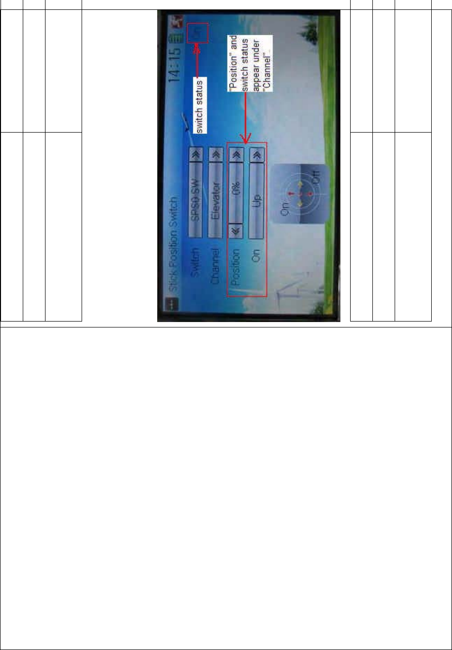
At the same time, “Position” and the status of turn-on or turn-off appear
under the item Channel. The current status of turn-on or turn-off will be
shown in the form of On or Off on the top right corner.
English Your language
Switch status
“Position” and switch status appear under
“Channel”
DEVO-8 Page no. Page 84 of 363
Click the icon to exit after the setting finished.
2.9 Warning
This function can set the warni ng f or unsafety of whic h stic k, switch
status, or flight mode stays at the position while turning on the device,
or is used as start-up warning in special purpose.
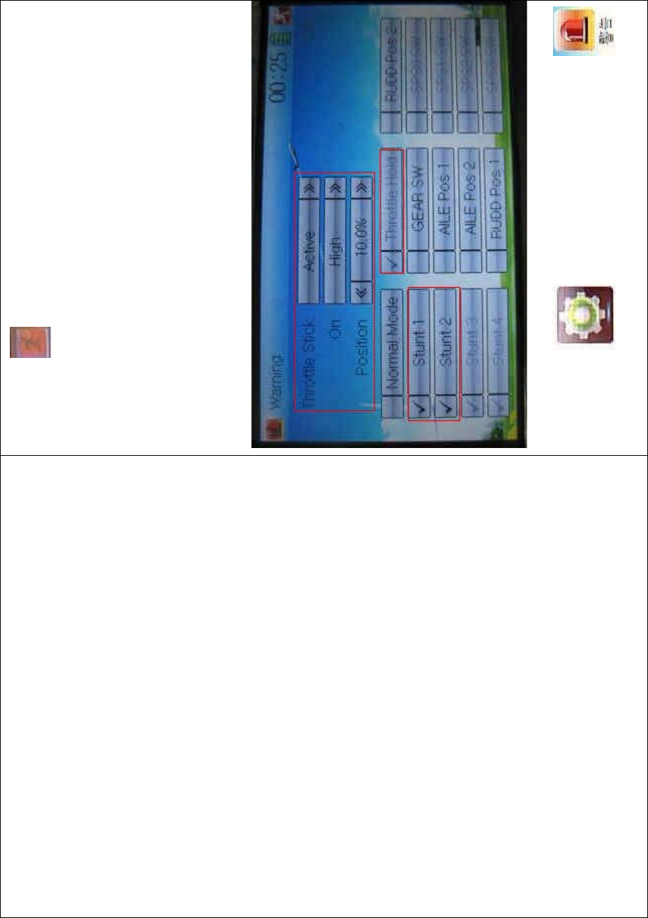
In factory, Throttle Stick is set as Active, High direction at 10.0%
Position, flight mode as Stunt, and Throttle Hold at on position.
To uc h t he i co n to enter Model Menu and then click
to enter the WARNING INTERFACE.

DEVO-8 Page no. Page 85 of 363
Setting method:
1) setting Throttle stick as warning
Click the navigation mark of Throttle Stick i n the interface of Warning. It
expands into Inhibit and Active. If Inhibit clicked, the dropdown menu is
retracted. If Active clicked, it will expand into two sub items: On and
Position.
The throttle stick can be set at either high or low position when startup
is warning, via clicking the navigation mark of On. The warning level
can be set by changing the percentage in Position, whose setting value
is ranged from 0.0 to 100.0%.
Take the ri ght-hand throttle as an example. Position is 0.0% when the
throttle stick is at the lowest position; Position is 100.0% when the
throttle stick is at the highest position. In factory, Throttle Stick is set as
Active, Position in High direction at 10.0%.
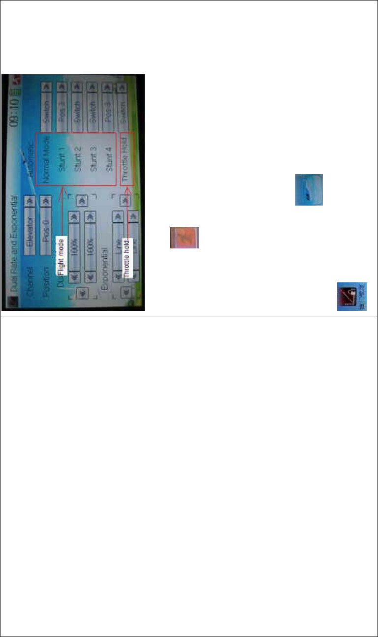
2) setting other items

DEVO-8 Page no. Page 86 of 363
Other flight modes and switches warning is shown in the lower-middle
part of the interface. Click the corresponding items you want to use. The
factory default setting includes Stunt 1, Stunt 2, Stunt 3, Stunt 4, and
Throttle Hold.
Click to exit.
2.10 Device select
This setting can help you configure various functio nal switches, or
adjust levers. It includes Flight Mode Main Switch, Flight Mode Extra
Switch, Stunt Trim Select, Throttle Hold Switch, Hovering Pitch, and
Hovering Throttle.
Friendly reminder: This function is frequently uti lized i n f lights.
Modelers will be greatly favored if expertly mastering its usage.
Setting method:
Touch the icon to enter Model Menu, and then click the
icon to enter Device Select.

DEVO-8 Page no. Page 87 of 363
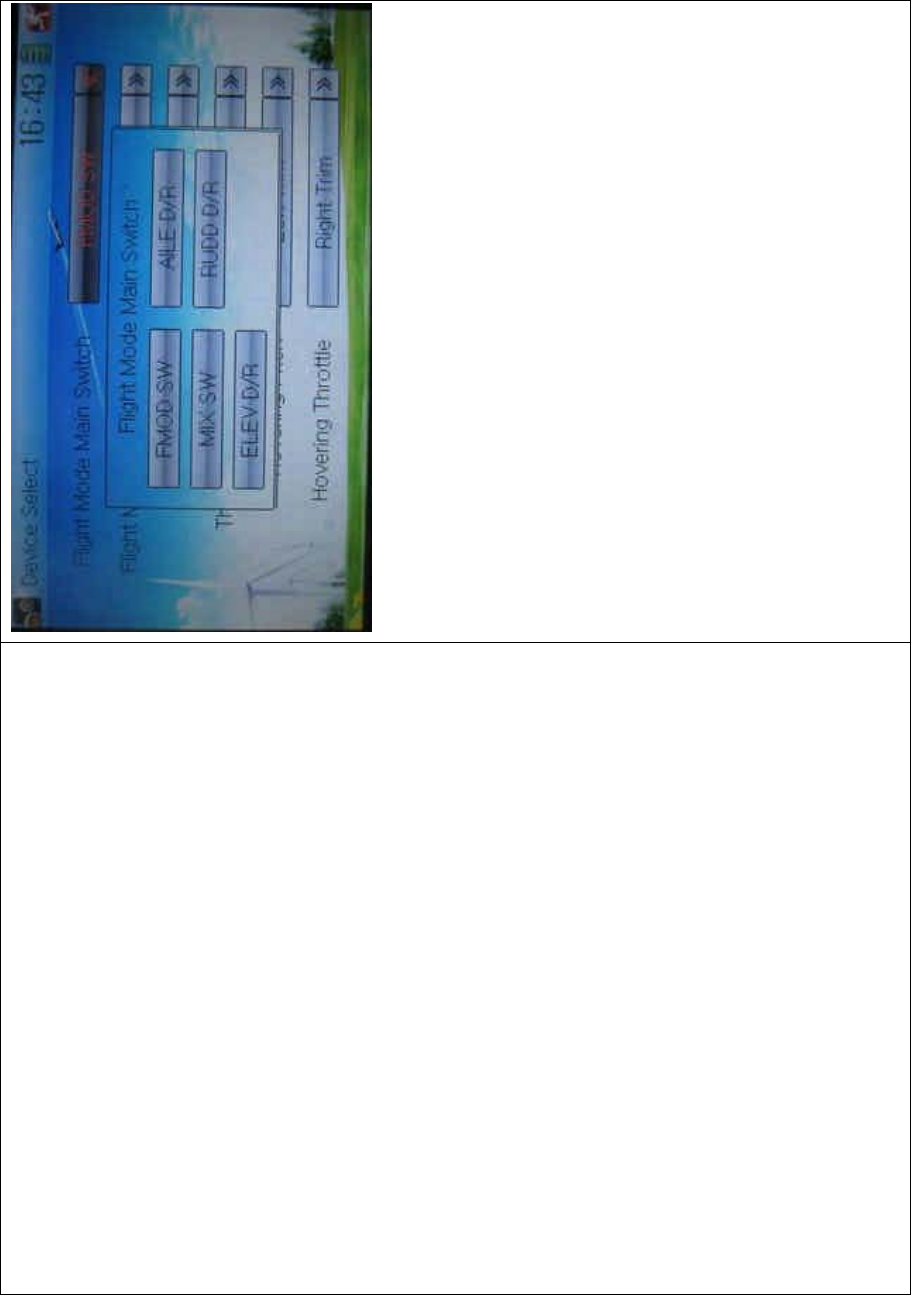
1) Flight Mode Main Switch
Touch the navigatio n mark of Flight Mode Main Switch and expand i nto
a dropdown menu, where to choose the mode switch you desire. The
factory default setting is FMOD SW.
DEVO-8 Page no. Page 88 of 363
2) Flight Mode Extra Switch
Refer to “Flight Mode Main Switch”.
3) Stunt Trim Select
There are two modes: Common and Flight Mode. In Common mode all
the trim values, which various sticks are corresponding to, put equally
effects on all the flight modes.
In Flight Mode, the trim value, which each stick is corresponding to,
puts independently effect on the corresponding stick. The factory
default is Common.
4) Throttle Hold Switch
Refer to “Flight Mode Main Switch”.
5) Hovering Pitch
Refer to “Flight Mode Main Switch”.

DEVO-8 Page no. Page 89 of 363
6) Hovering Throttle
Refer to “Flight Mode Main Switch”.
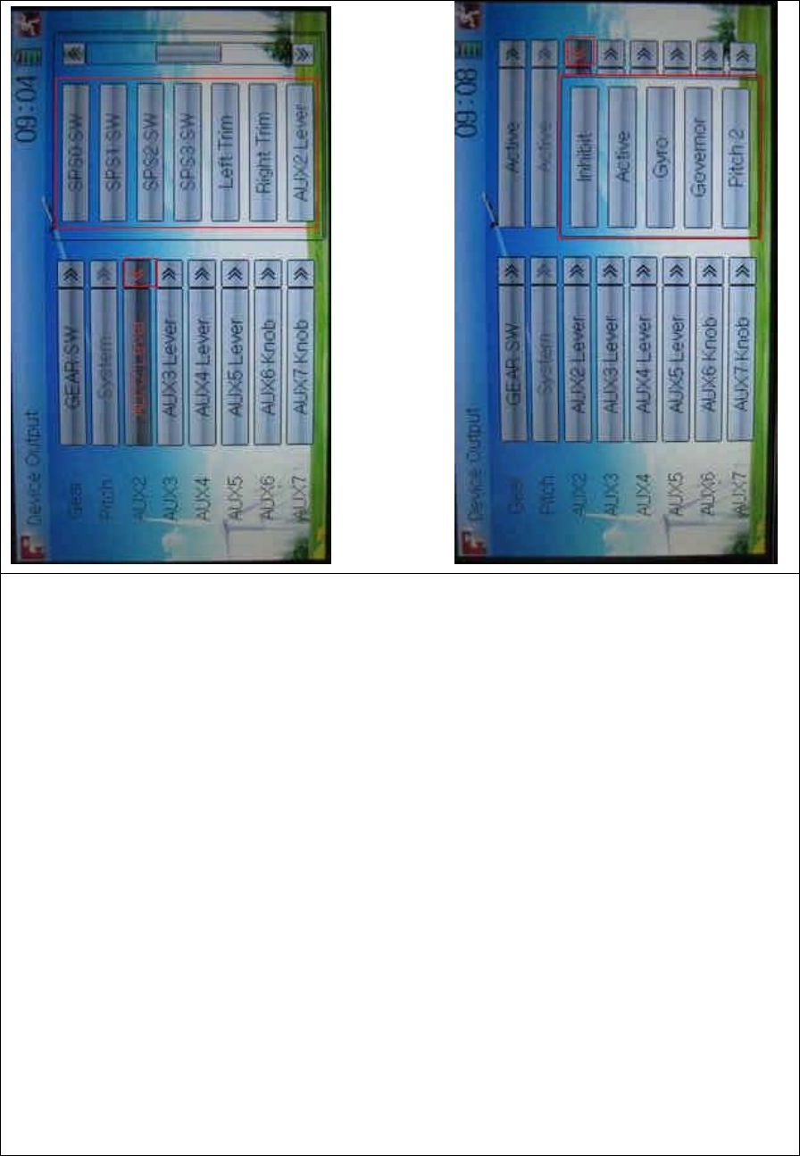
2.11 Device Output
Device output is composed of eight items. It can set up the output
switches and select the usage of levers, respectively. It can also
activate, inhibit or use other functions.
Friendly reminder: This function is frequently uti lized i n f lights.
Modelers will be greatly favored if expertly mastering its usage.
Setting method:
Touch the icon to enter Model Menu and then click
to enter the DEVICE OUTPUT INTERFACE.

DEVO-8 Page no. Page 90 of 363
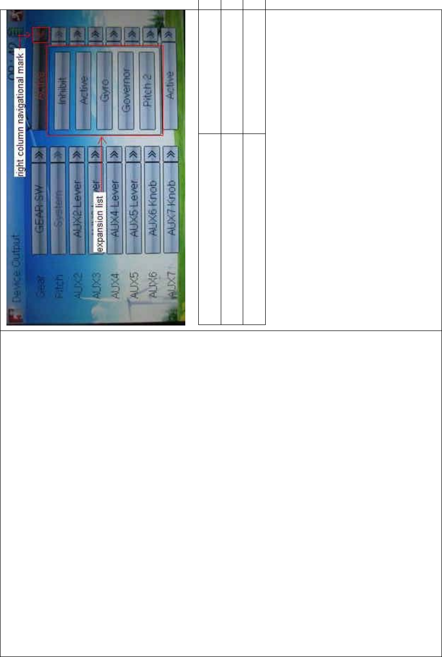
There are eight adjustable items. They are Gear, Pitch, AUX2, AUX3,
AUX4, AUX5, AUX6, and AUX7, respectively. The setting methods for
them are shown below:
1) Gear
Touch the left column navigation mark of Gear and pop up an
expansion list including FMOD SW, MIX SW, ELEV D/R, AILE D/R,
RUDD D/R, HOLD D/R, and GERA SW. Touch the desired item. The
default setting is GEAR SW.

DEVO-8 Page no. Page 91 of 363
English Your language
Touch navigation mark
Expansion of GEAR SW
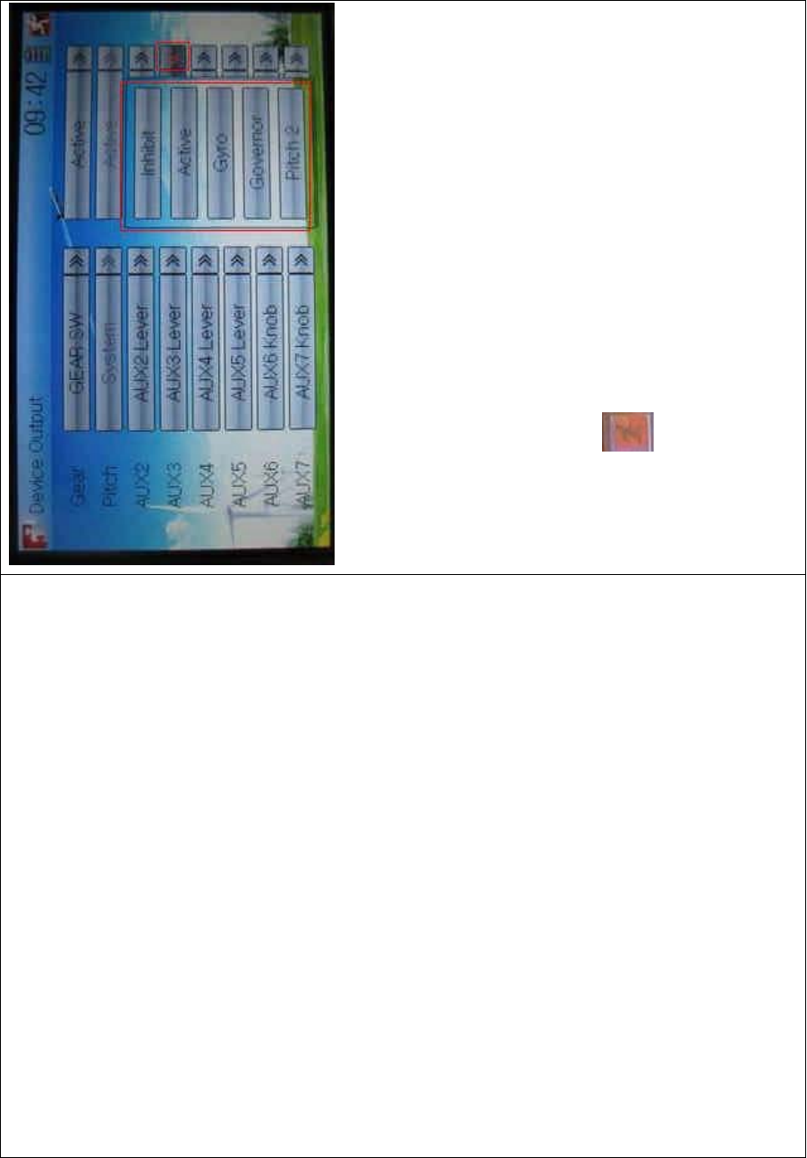
Touch the right column navigation mark of Gear. Pop up an expansion
list including Inhibit, Active, Gyro, Governor, and Pitch 2. Touch the
desired item. The default setting is Active.
DEVO-8 Page no. Page 92 of 363
English Your language
Right column navigation mark
Expansion list
1) Pitch
The item is programmed as system default. Any setting is unavailable.
2) AUX 2
Touch the left column navigation mark of AUX 2. Pop up an expansion
list including SPS0 SW, SPS1 SW, SPS2 SW, SPS3 SW, Left Trim,
Right Trim, and AUX2 Lever. Touch the desired item. The default setting
is AUX2 Lever.
DEVO-8 Page no. Page 93 of 363
Touch the right column navigation mark of AUX 2, and expands a list
including Inhibit, Active, Gyro, Governor, and Pitch 2. Click the desired
item. The default setting is Active.

DEVO-8 Page no. Page 94 of 363
Then continue to set other items.
3) AUX 3
Touch the left column navigation mark of AUX 3, and expands a list
including AUX3 Lever, AUX4 Lever, AUX5 Lever, AUX6 Knob, AXU7
Knob. Touch the desired item. The factory default setting is AUX3
Lever.
Click the right column navigation mark of AUX3, and see an expansion
list including Inhibit, Active, Gyro, Governor, and Pitch 2. Choose the
desired item. The factory fault setting is Active. Then continue to set up
other items.
DEVO-8 Page no. Page 95 of 363
4) AUX 4
Refer to “4) AUX 4”.
5) AUX 5
Refer to “4) AUX 4”.
6) AXU6
Refer to “4) AUX 4”.
Click the icon to exit.
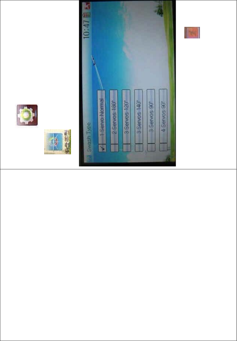
2.12 Swash type
The swash type is grouped into six options: 1 Servo Normal, 2 Servos
180°, 3 Servos 140°, 3 Servos 90°, and 4 Servos 90°.
DEVO-8 Page no. Page 96 of 363
Setting method:
Touch the icon to enter Model Menu, and then click the
icon to enter the SWASH TYPE INTERFACE.
Choose the desired swashplate and then click the icon to exit.
2.13 Fixed ID
DEVO-8 Page no. Page 97 of 363
This setting will bind DEVO-8 and its receiver in a unique corresponding
relationship. It will greatly speed up the time of automatic binding when
DEVO-8 powered on.
1) Setting for fixed ID
The setting for fixed ID should be under the status that automatic ID
binding is successfully finished. Below is the setting method.
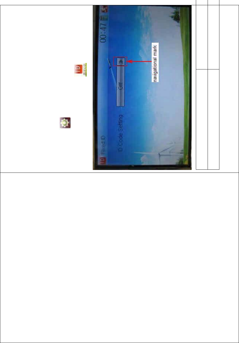
Touch the icon to enter Model Menu, and then enter the
interface of Fixed ID by touching the icon .
English Your language
Navigation mark
Touch the navigation mark of the item ID Code Setting. It will expand
DEVO-8 Page no. Page 98 of 363
into two statuses: Off and On. A series of random digits will be shown
below after touching On.
English Your language
To uc h “O n”
A series of random digits is shown here
A mini soft keyboard is shown in t he lower part after touc hi ng the
random digits of ID Code
DEVO-8 Page no. Page 99 of 363
English Your language
Mini soft keyboard
The new ID digits can be modified by touching the mini soft keyboard.
Then touch Match after the new ID is already set. An INQUIRY
interface of “Are you sure?” pops up. “ID Code Match … …” will be
shown after touching OK.

DEVO-8 Page no. Page 100 of 363
English Your language
ID Code Setting
ID Code
Fixed ID
Are you sure?
Cancelled
ID Code Match
2) Fixed ID cancellation
Insert the assorted BIND PLUG into the output terminal of BATT before
the receiver is powered on, and then plug 5V DC power into one of the
other output terminals. The red light of receiver will flash slowly. This
means the fixed ID code has been cancelled. P ull out BIND PLUG.
DEVO-8 Page no. Page 101 of 363
DEVO-8 also needs to make relative cancellation and reversion after
the fixed ID in receiver is cleared out.
In the mai n interface touch the icon to enter Model Menu and
then touch to enter Fixed ID. Touch ID Code Setting to expand
the navigation mark into two statues On and Off. Touch Off. Then touch
to exit.
3.0 Function Menu
Function Menu can help you make CUSTOM adjustments for the
selected models. The menu includes such items as Reverse Switch,
Travel Adjust, Sub Trim, Dual Rate and Exponential, Throttle Hold,
Throttle Curve, Mix to Throttle, Gyro Sensor, Governor, Tail Curve, Dual
Pitch, Swash Mix, Pitch Curve, Program Mix, Monitor, Fail Safe, Trainer,
and Timer.
3.1 Reverse Switch
DEVO-8 Page no. Page 102 of 363
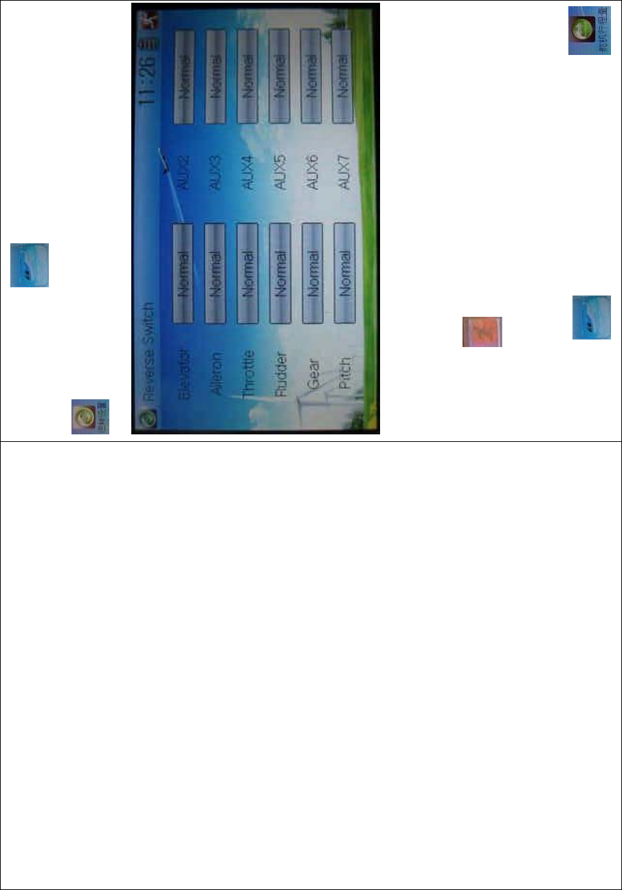
Touch the shortcut icon to enter Function Menu, and then click
to enter the REVERSE SWITCH INTERFACE.
The statues of total 8 channels are shown in the interface. Touch the
relative channel for Normal or Reverse switch. The default setting is
Normal.
Click the icon to exit.
3.2 Travel adjust
Touch the icon to enter Function Menu and then click
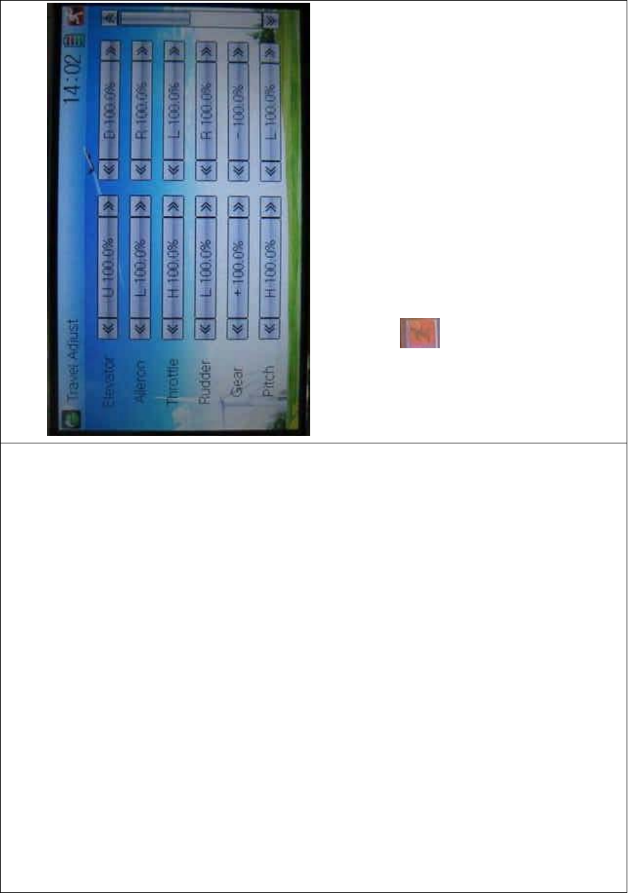
DEVO-8 Page no. Page 103 of 363
to enter the TRAVEL ADJUST INTERFACE.
Touch the navigation mark of the desired item to increase or decrease
the servo travel rang. The adjustment range is from 0.0% to 150.0%.
The factory default is 100.0%.
Click the icon to exit.
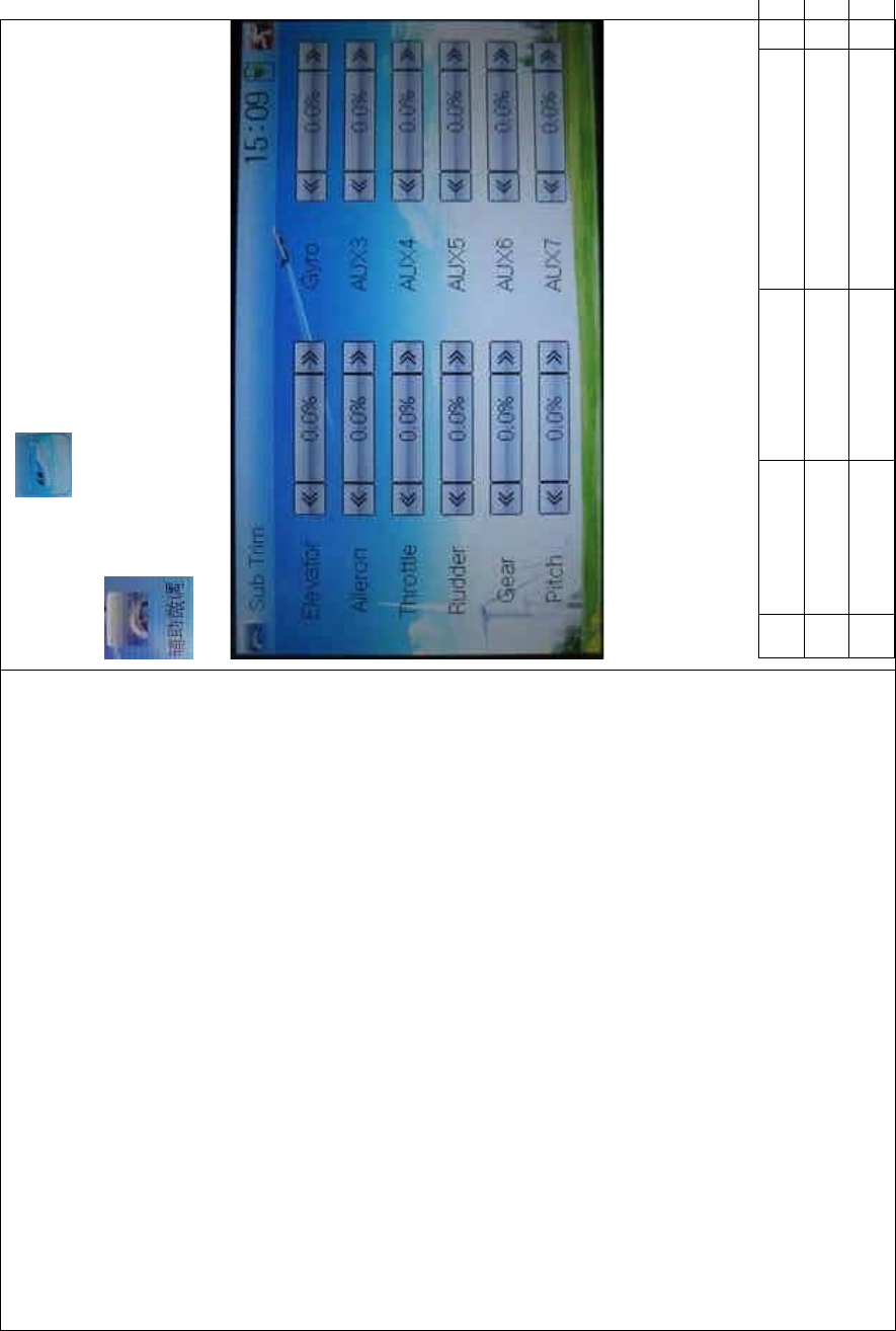
3.3 Sub Trim
Sub Trim can parallel to move the neutral point of the servo. But we
advise you to mechanically adjust the servo bell crank if offset is far
away from the neutral point of servo, because excessive usage of the
sub trim, out of its range, may damage the servo.
Setting method:
DEVO-8 Page no. Page 104 of 363
Touch t he ico n to enter Function Menu and then click
to enter Sub Trim.
It is possible to change the servos’ neutral point by touching the
navigation mark of the desired item to amend the percentage. The
default for each channel is 0.0%. The following chart shows you the
adjustment range of each channel:
English Your language English You
r
Channel name Adjustment range
1 Elevator D62.5%-U62.5%
DEVO-8 Page no. Page 105 of 363
2 Aileron R62.5%-L62.5%
3 Throttle L62.5%-H62.5%
4 Rudder R62.5%-L62.5%
5 Gear -62.5%- +62.5%
6 Pitch L62.5%- H62.5%
7 AUX2 -62.5%- +62.5%
8 AUX3 -62.5%- +62.5%
9 AUX4 -62.5%- +62.5%
10 AUX5 -62.5%- +62.5%
11 AUX6 -62.5%- +62.5%
12 AUX7 -62.5%- +62.5%
To uc h to exit.
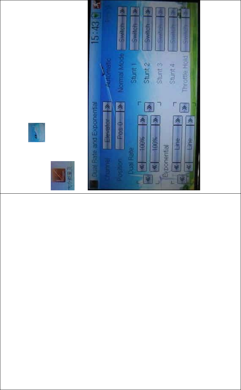
3.4 Dual Rate and Exponential
Afterthisfunctionissetup,itispossibleforD/Rswitchestocontrolthe
dual rates of elevator, aileron, and rudder, respectively. The setting
range is covered from 0% to 125%. Under the help with exponential
curveadjustment,itispossibletomakebothcustomizedsettingsand
automatic settings.
The switch between Dual Rate and Exponential can be performed via
DEVO-8 Page no. Page 106 of 363
pushing or pulling the Flight Mode lever.
Setting method:
Touch t he ico n to enter Function Men
u and then click
to enter the interface DUAL RATE AND
EXPONENTIAL INTERFACE.
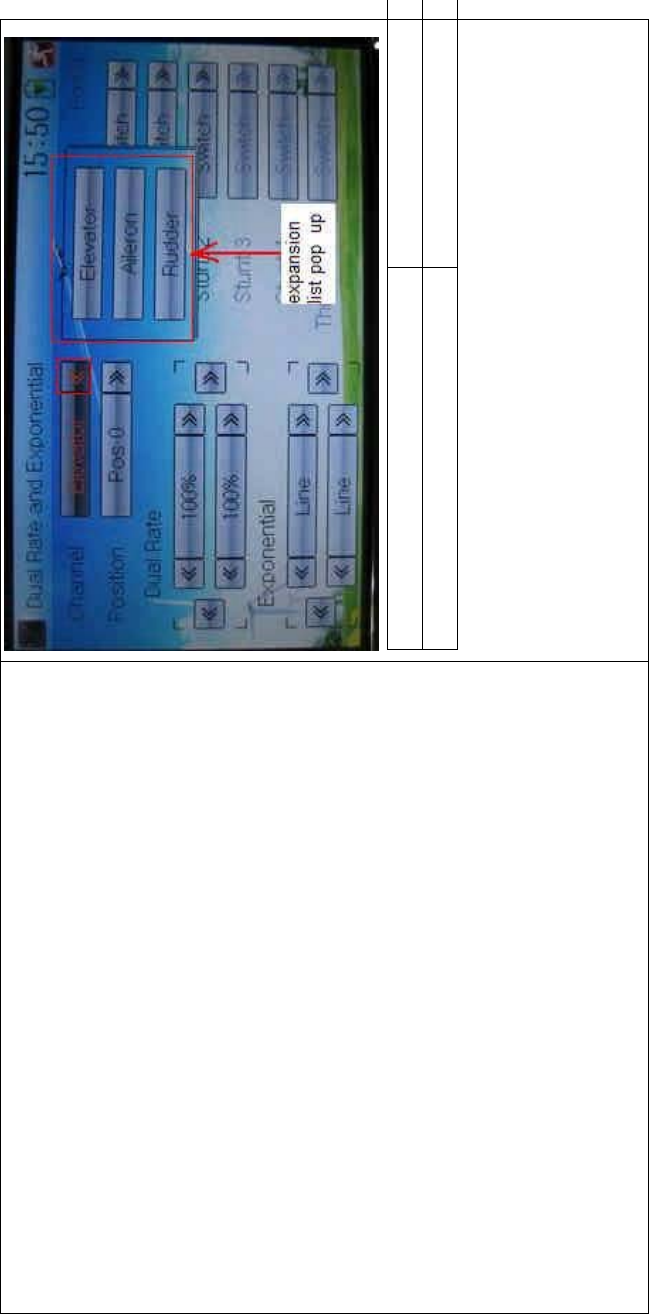
1) Channel selection
Touch the navigation mark of Channel. A n expansio n list pops up, whic h
contents Elevator, Aileron, and Rudder. Choose the desired channel for
setting.
DEVO-8 Page no. Page 107 of 363
English Your language
Expansion list pops up
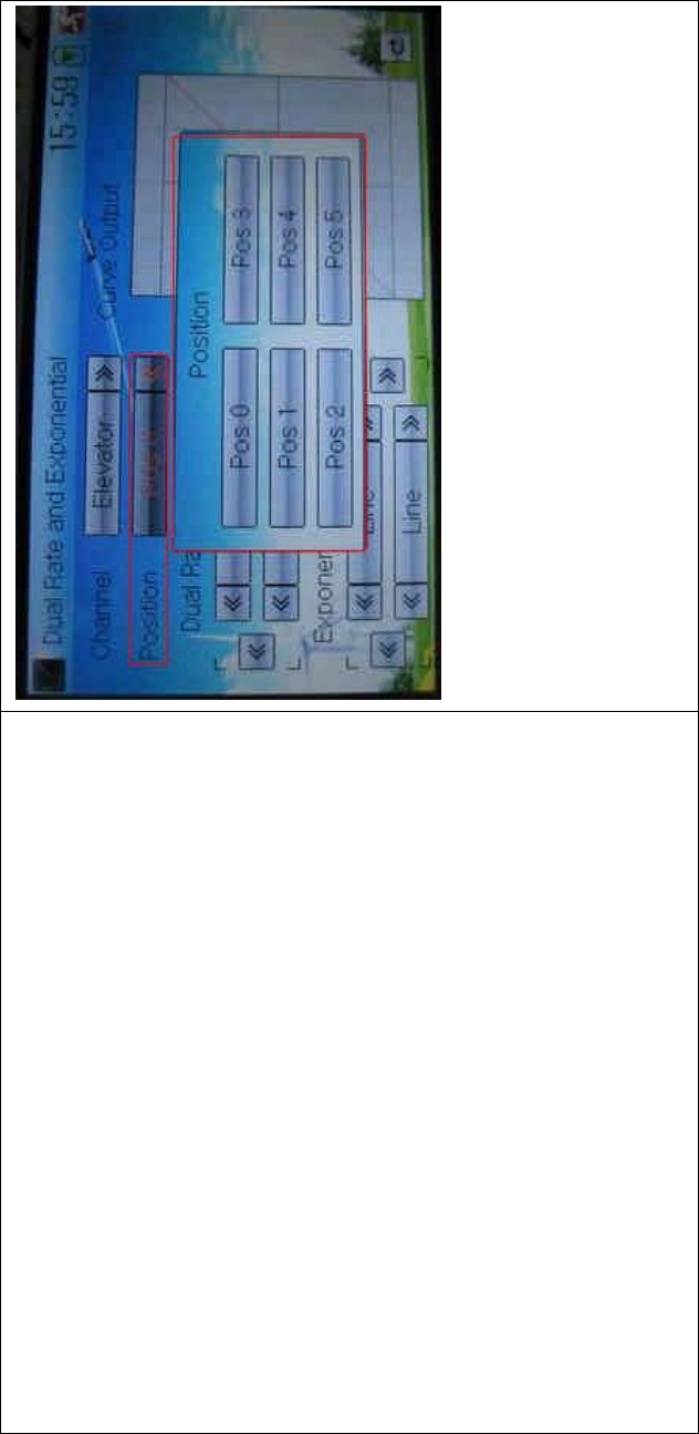
2) Position selection
Touch the navigation mark of Position. An expansion list pops up, where
there are six points for you choosing from Pos 0 through 5. Chose the
position you want to set. The chosen point will be shown in the frame of
the item Position.
DEVO-8 Page no. Page 108 of 363
In manual mode, the function of Dual Rate and Exponential will be
executed by the corresponding dual rate switch among Pos 0, Pos 1,
and Pos 2.
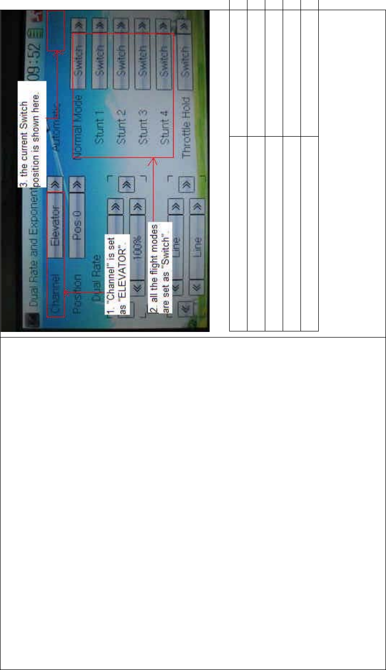
Take the item Elevator at Channel as the example. All the flight modes,
shown in the right column, are set as “Switc h”. T hen if we move the
lever of ELEV D/R, the switch will be taken place among Pos 0, Pos 1,
and Pos 2.

DEVO-8 Page no. Page 109 of 363
If moving the lever ELEV D/R (shown above), switch will happen among
Pos 0, Pos 1, and Pos 2 (shown below).
DEVO-8 Page no. Page 110 of 363
English Your language
ELEV D/R
“Channel” is set as “Elevator”
All the flight modes are set as “Switch”
The current Switch position is shown here
3) Dual Rate adjustment
It is possible to modify the dual rate value by touching the navigation
mark of Dual Rate.

DEVO-8 Page no. Page 111 of 363
If touchi ng the navigatio n mark for just one item to amend the dual rate
value, the dual rate of the correspondi ng servo wi ll be changed in one
direction, while the curve will being changed in one direction at the right
graph.
If touching the navigation mark for both items to amend the dual rate
value, the dual rate of the corresponding servo will be changed while
the curve will being changed at the same time, shown at the right graph.
The default setting is 100%.
English Your language
Upper curve
Lower curve
If touch this mark, both the upper and
lower curves will being c hanged at t he
same time.
If touch this mark, upper or lower curve
will being changed.
DEVO-8 Page no. Page 112 of 363
4) Exponential adjustment
It is possible to adjust the exponential output value of the servo at that
point, which is set up in step “2) Position selection”, by touching the
navigation mark of Exponential.
If touchi ng the navigatio n mark for just one item to amend the dual rate
value, the dual rate of the correspondi ng servo wi ll be changed in one
direction, while the curve will being changed in one direction at the right
graph.
If touching the navigation mark for both items to amend the dual rate
value, the dual rate of the corresponding servo will be changed while
the curve will being changed at the same time, shown at the right graph.
The default setting is Line.
Then to uc h this mark to return to the interface of Dual Rate and
DEVO-8 Page no. Page 113 of 363
Exponential.
5) Automatic setting
Under working with Flight Mode, it is possible to switch the dual rate
and exponential, which are set in above “3) Dual Rate adjustment” and
“4) Exponential adjustment”, respectively.
The settings for Normal Mode, Stunt 1, Stunt 2, Stunt 3, Stunt 4, and
Throttle Hold are available. But for Stunt 3 and Stunt 4, Flight Mode
Extra Switch at Device Select in Mode Menu should be activated (Refer
to “2.10 Device Select”), and Throttle Hold in Function Menu should be
set as “Active” (Refer to “3.5 Throttle Hold” below).
Touch the flight mode that you want to set as automatic operation, and
an expansion list will be shown. Click the desired position. If Switch is
selected, it is only controlled by the corresponding dual rate lever.
DEVO-8 Page no. Page 114 of 363
Click the icon to exit.
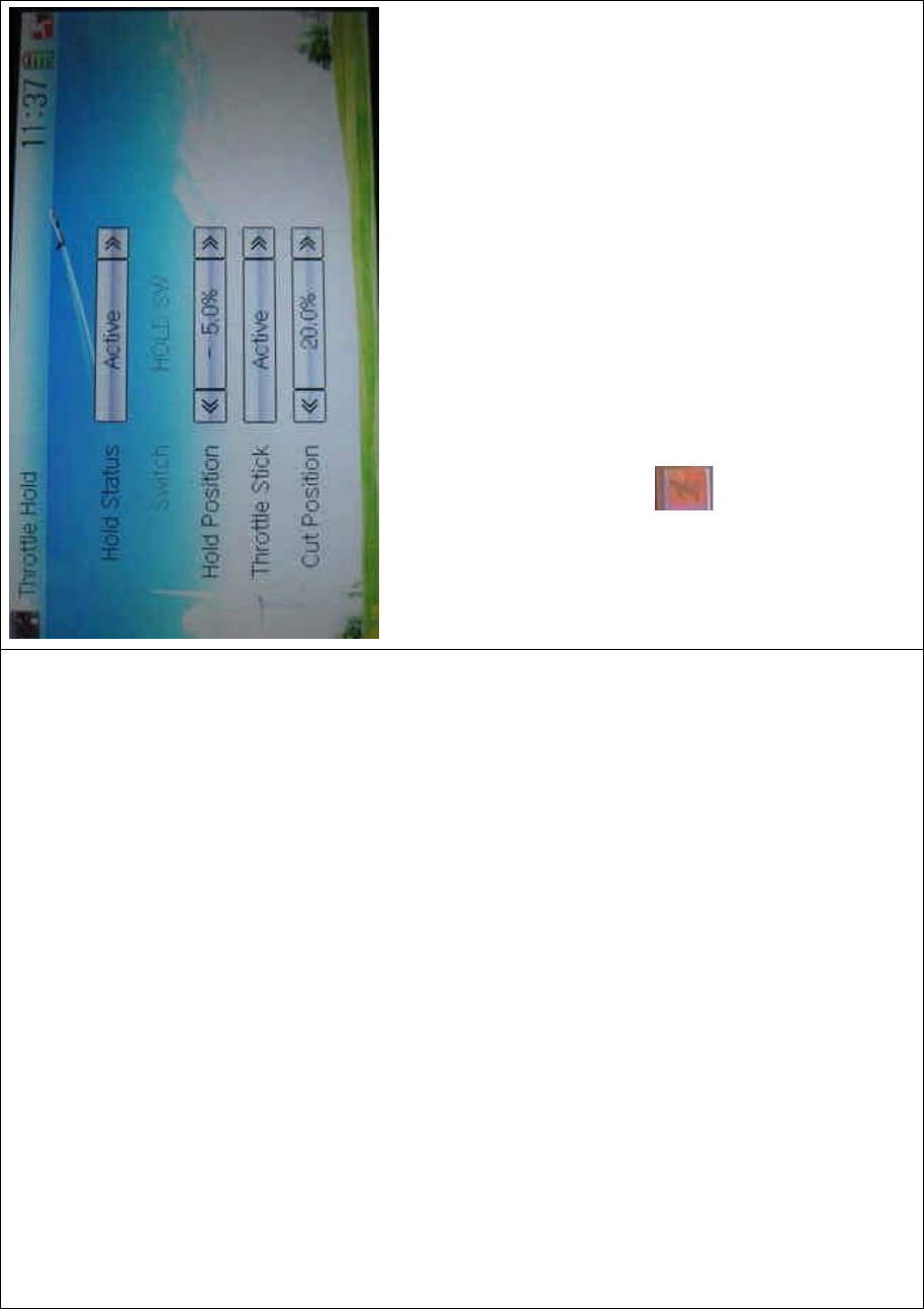
3.5 Throttle hold
If this function is set, the switch will be executed by hold switch. The
settingvalueofthrottleholdisrangedfrom-20.0to50.0DŽ
Setting method:
Touch the shortcut icon to enter Function Menu, and then click
to enter the THROTTLE HOLD INTERFACE.
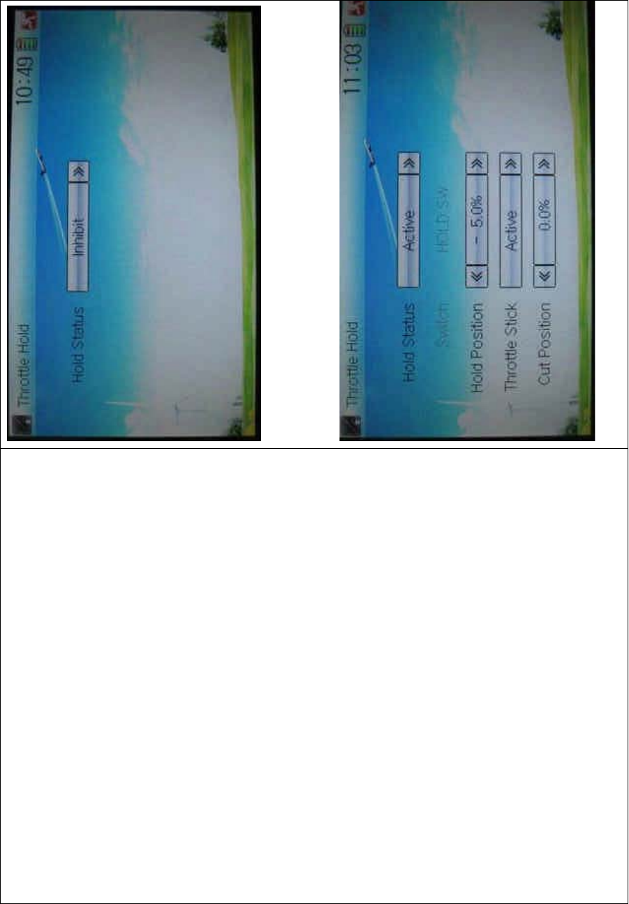
DEVO-8 Page no. Page 115 of 363
Touch the navigation mark of Hold Status, and an expansion list will be
shown as Inhibit and Active. Click Active, there appeared Switch, Hold
Position, and Throttle Stick in the following interface.
1) Setting for Switch
DEVO-8 Page no. Page 116 of 363
This item is impossible to be set. The default setting is HOLD SW.
2) Setting for Hold Position
Touch the left or right navigation mark of the item Hold Position to
decrease or increase, respectively, the position amount, whose range is
covered from -20.0% to +50.0%.
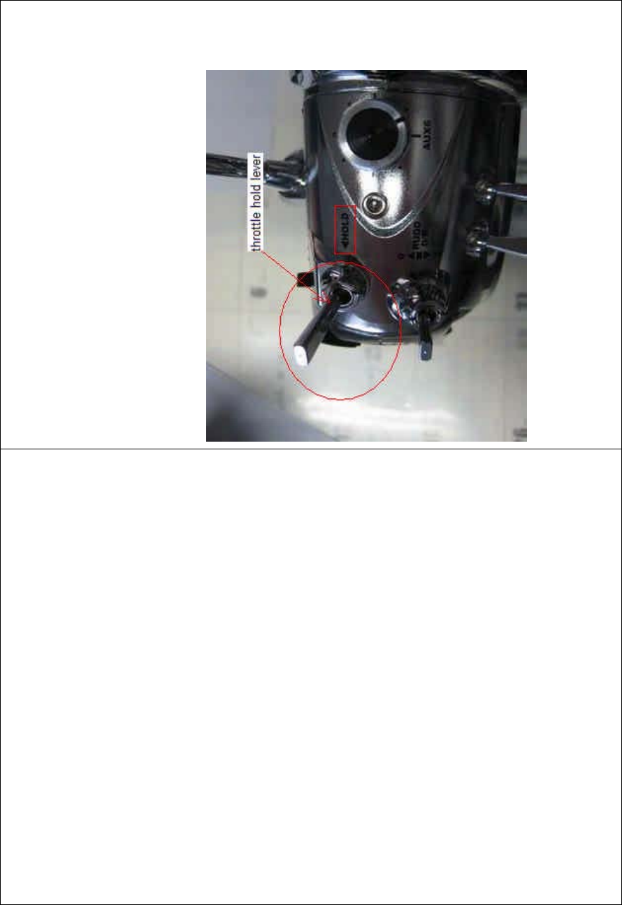
3) Setting for Throttle Stick
Given the function is used. If the throttle hold lever is turned on, it is
possibletosetthethrottlestickastheswitchthatentersthestatusof
throttle holding.
Setting method:
Touch the navigatio n mark of Throttle Stick and an expansion list wi ll be
shown as Inhibit and Active. Click Active and pop up a dropdown menu
of Cut Position.
DEVO-8 Page no. Page 117 of 363
Touch the left or right navigation mark of Cut Position to decrease or
increase, respectively, the amount whose range is covered from 0.0%
to 100.0%.
Under Throttle Hold turned on (pull the Throttle Hold lever forward),
when moving the throttle stick to the point set by Cut Position from high
to low, the throttle enters the locked status. That means the throttle is
locked at the point set by Hold Position.
If pushing Throttle Hold lever, the throttle locked status is released.
Click the icon to exit after all the settings are finished.
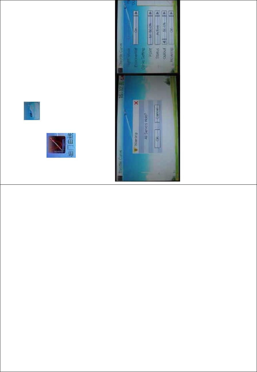
3.6 Throttle curve
Throttlecurvesareadjustedthroughninepoints,whichofalltheflight
modes can be respectively set. The flight mode includes Normal Flight,
Stunt1,Stunt2,Stunt3,andStunt4whileFlightModeExtraSwitchin
DEVO-8 Page no. Page 118 of 363
Device Select should be activated (Refer to “2.10 Device Select”).
Setting method:
Touch the shortcut icon to enter Function Menu, and then click
the icon to enter the interface of Throttle Curve while an
enquiry dropdown is shown “All Servos Hold?” If click OK, all the servos
will be locked at the current status; if click Cancel, all the servos will be
unlocked at the current status. Enter the following interface after
clicking OK or Cancel.
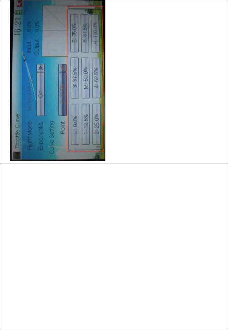
1) Adjustment for Exponential
Touch the navigation mark of Exponential and expand an option
dropdown: Off and On. The throttle curve will be changed smoothly if
touchi ng On, or i n fold line if clic king Off.
2) Curve Setting
It includes two items: Point, and Output.
2.1) Adjustment for Point
Touch the navigation mark of Point and an expansio n list i nc luding ni ne
DEVO-8 Page no. Page 119 of 363
points is shown. Click the point which you want to adjust.
2.2) Status adjustment
Touch the navigation mark of Status and drop down a menu including
Inhibit and Active. Click Inhibit if you don’t amend the amo unt of the
selected point which is set in “2.1 Adjustment for Point” (the factory
default setting is Inhibit). Click Active if you want to amend the amount
of the said point, and an expansion list including Output and Hovering is
shown below.
2.3) Output adjustment
Touch the left or right navigation mark of Output to decrease or
increase, respectively, the output amount of the selected point with a
minimum of 0.0% and a maximum of 100.0%.
2.4) Hovering adjustment
After the setting in “2.3 Output adjustment” is finished, it is necessary to

DEVO-8 Page no. Page 120 of 363
set t he item of Hovering as On and all the selected points of the throttle
curv e sho uld be activated if using throttle trim in flight is a must. The
seven points of 1-3, M, 4-7 in the curve will being paralleled up or down
withthechangingofthrottletrim.Sothethrottlecurvewillbeing
paralleled up or down with the movements of the seven points.
3) Flight mode
There are total five flight modes: Normal Flight, Stunt 1, Stunt 2, Stunt 3,
and Stunt 4, the curve of which can be respectively set in their
corresponding flight mode. The setting method is same with “2) Curve
Setting” above. Regarding the setting for Flight Mode, please refer to
“2.10 Device Select”.
Click the icon to exit.
3.7 Mix to throttle
This function can keep the main rotor blades running at the certain
revolution caused by the changed load when operating the aileron
servo, elevator servo, and rudder servo. Generally, it is not advised to
use this f unction.
Setting method:
Touch the shortcut icon to enter Function Menu, and then click
the icon to enter the MIX TO THROTTLE INTERFACE.
DEVO-8 Page no. Page 121 of 363
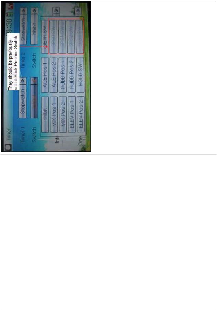
We can select the desired item except these items of SPS0 SW, SPS1
SW, SPS2, and SPS3 which should be previously set at Stick Position
Switch at Model Menu (refer to “2.8 Stick Position Switch”).
1) Set time
The settable countdown time range is from 00:05 to 59:55.
2) Interval
This item offers the possibility to set the warning interval. It will warn
once every interval time. The adjustable range is from 00.05 to 05:00.
The default setting is Inhibit.
3) Down alarm
It is possible to set the down alarm in countdown. The setting range is
from 00:01 to 03:00. The default setting is Inhibit.
4) One time
If this function is turned on, counting down cannot be stopped once the
countdown works. The default setting is Off.

DEVO-8 Page no. Page 122 of 363
B. Setting for Timer 2 is same as that for timer 1.
Touch the icon to exit after finished.
Part three: Airplane
1.0 System menu
The boot screen of airplane is shown as below:
DEVO-8 Page no. Page 123 of 363
N/O English Your language N/O English Yo
u
1 Elevator trim 11 Aileron trim
2Flaptrim 12
System menu
icon
3 Flight mode 13 Function
menu icon
4 Timer 14 Model name
5Throttle percentage
value 15
Battery
volume
display
6 Throttlecurveicon 16 Timedisplay
7 Rudder trim 17 Transmission
power display
8D/R & exponential
icon 18
9 Model menu icon 19 Throttle trim
10 Gyro sensor icon 20
1.1 Language setting
Touch the s hortcut icon to ente
r System Menu and then touch
to enter Language. Touch the language that you want to select. A

DEVO-8 Page no. Page 124 of 363
ĀĜ” will be shown on the screen after selected.
Then touch to save and exit.
1.2 Skin selection
DEVO-8 offers three skins for your selection.
Touch to enter System Menu and touch to enter Skin.

DEVO-8 Page no. Page 125 of 363
Touch the skin yo u desire and then touch to exit.
1.3 Display
Touch the shortcut icon to enter System Menu and then
touch the icon to enter “Display”.

DEVO-8 Page no. Page 126 of 363
Five items are available to be set. Below are the setting methods for
them:
1) LCD brightness: it is possible to increase or decrease the LCD
brightness by touching the navigation marks. The power
consumption will be increased if the LCD is too bright and will the
battery cruise duration will also be shortened.
2) LCD contrast: the contrast can be adjustable by touching the
navigation marks. The power consumption will be increased if the
contrast is too high and the battery cruise duration will be
shortened.
3) Backlight lightness: the backlight lightness can be adjustable by
touching the navigation marks. The power consumption will be
increased if the backlight lightness is too bright and the battery
cruise duration will be shortened.
4) Backlight time out: it is possible to set the duration which LCD stays
at highlight in the form of Always on and duration from 5 to 60

DEVO-8 Page no. Page 127 of 363
seconds with an interval of 5 seconds.
5) Power save time: it can adjust the backlighting duration by turning
off the backlight in order to prolong the battery cruise time. The
setting status contents Always On and duration in 30 grades with an
interval of 1 minute.
To uc h to exit.
1.4 Buzzer warning
To uc h t he i co n to enter System Menu and then touch
to enter Buzzer interface
1) Buzzer switch: touch the navigation mark at Buzzer Switch and pop
up an alternative item: Off and On. If touching On, a drop-down

DEVO-8 Page no. Page 128 of 363
menu will be shown below.
2) Throttle stick: under Buzzer Switch is at the status of On, if Throttle
Stick is set as “Active”, a relative musical scale will make response
when moving the throttle stick. You can judge the position of the
throttle stick according to the different musical scales. Also, it can
be set as Inhibit.
3) Levers and knobs: under the condition that this item is set as
“Active”, DEVO-8 will sound when rotating or moving such levers or
knobs as AUX2, AUX3, AUX4, AUX5, AUX6, and AUX7 to their
neutralpositions.Itiscanbesetas“Inhibit”.
4) Buzzer tone: the tone is composed of 10 grades. You can choose
thefavoritetoneaccordingtoyourinterests.TouchTesttomakea
listening test.
To uc h to exit after finished.
1.5 Date & Time
To uc h t he i co n to enter System Menu and then touch
to enter the item of “Date & Time”.
DEVO-8 Page no. Page 129 of 363
The clock setting is grouped into Year, Month, Day, and Time. Touch the
navigation marks, respectively, to make modifications.
To uc h to save and exit.
Note: if incorrect turn on time or production time appears, one
possibility is that the power supply for the clock is not enough.
Replacing a new button cell is a must.
The method for changing button cell:
Turn off the power of your DEVO-8 and take off its battery pack. Use a
cross screwdriver to remove the two fixing screws on the fixing board.

DEVO-8 Page no. Page 130 of 363
English Your language
Fixing screws
Push outwards the button cell holder, and the button cell will
automatically pop up. Replace the old cell with a new one.
DEVO-8 Page no. Page 131 of 363
Cell size: CR 1220 3V
English Your language
Button cell holder
Push outwards
1.6 TFT screen calibration
To uc h t he i co n to enter System Menu and then touch
to enter TFT Screen Calibration.
DEVO-8 Page no. Page 132 of 363
Click anywhere on the screen to start calibration with the touch pen,
and then follow the indication to calibrate. It will automatically return to
System Menu after the calibration is finished.
1.7 Stick mode
Touch the icon to enter System Menu, and then touch the
icon to enter Stick Mode.
DEVO-8 Page no. Page 133 of 363
There are four stick modes from MODE 1 to MODE 4. Select the stick
mode you desire and then to uch the icon to exit.
1.8 Stick and lever
To uc h t he ico n to enter System Menu and then touch the
icon to enter Stick and Lever. There are two items in the
interface: Stick Direction and Stick & Lever Calibration.

DEVO-8 Page no. Page 134 of 363
1) Stick direction: there are four options: Elevator, Aileron, Throttle,
and Rudder. Click the item, which you want to reverse, to change
the output direction of the stick. The default setting is Normal.
2) Stick & lever calibration: if variance happened in sticks or levers, it
wouldbecalibratedviathisoption.
Method for calibration:
Click the display item of Start to enter the status of calibration, and Start
will be turned into Stop.
2.1) Stick calibration: Clockwise or counter clockwise mechanically
move the right stick and left sticks from their minimum levels to their
maximum levels several times, and then return the sticks to the neutral
positions, respectively.
2.2) Lever calibration: mechanically move the levers of AUX2, AUX3,
AUX4, and AUX5, respectively, from the minimum level to the maximum
level several times, and then return to the neutral positions,

DEVO-8 Page no. Page 135 of 363
respectively.
2.3) Click the display item of Stop. If the calibration is finished,
“Calibration success!” will be shown on the lower of the screen. If the
calibration is failed, “Calibration error! Please try again!” will be shown
instead. It needs to be calibrated again.

DEVO-8 Page no. Page 136 of 363
English Your language
Normal
Reverse
Stick direction
Stick & lever calibration
Start
Stop
Calibration success
Calibration error! Please try again!
2.4) Re-calibration: directly repeat the said steps 2.1 and 2.2 in the
failure interface.

DEVO-8 Page no. Page 137 of 363
Touch the icon to exit.
1.9 Power amplifier
The transmission output power of DEVO-8 is adjustable. It is divided
into six grades from small to big. The lower the transmission output
power transmits, the shorter the radio range is, and the longer the
stand-by time will be. The higher the transmission output power, the
farer the radio range, and the shorter the stand-by time. Choose the
appropriate transmission output power according to the actual situation.
To uc h t h e i c o n to enter System Menu and then click to
enter the POWER AMPLIFIER INTERFACE.
Choose the appropriate output power level and then touch to exit.
DEVO-8 Page no. Page 138 of 363
1.10 About
To uc h t he i co n to enter System Menu and then touch
to get access to the ABOUT INTERFACE. You can check
the versions of hardware and software.
Click the icon to exit.
2.0 Model menu
Model Menu manages all the model data saved in DEVO-8. It includes
Model Select, Model Name, Model Copy, Model Transmit, Model
DEVO-8 Page no. Page 139 of 363
Receive, Model Reset, Type Select, Trim System, Stick Position,
Warning, Device Select, Device Output, Wing Type and Fixed ID.
2.1 Model select
Touch the icon to enter Model Menu and then click the icon
to enter Model Select.
Touch the model you desire. The selected model is changed in orange
color. Then click the icon to exit.
2.2 Model name
In the menu of Model Name, you can make a desired name for your
DEVO-8 Page no. Page 140 of 363
model for long term storage. Its data can be directly withdrawn in the
next f lights.
Repeat the step “2.1 Model Select” to choose the model you want to
name or save. And then to uc h the icon to exit.
Click the icon to enter System Menu and then click the icon
to get the MODEL NAME INTERFACE. The following is
the interface:
Click the right blank frame of Name and a gray stripe will be shown in
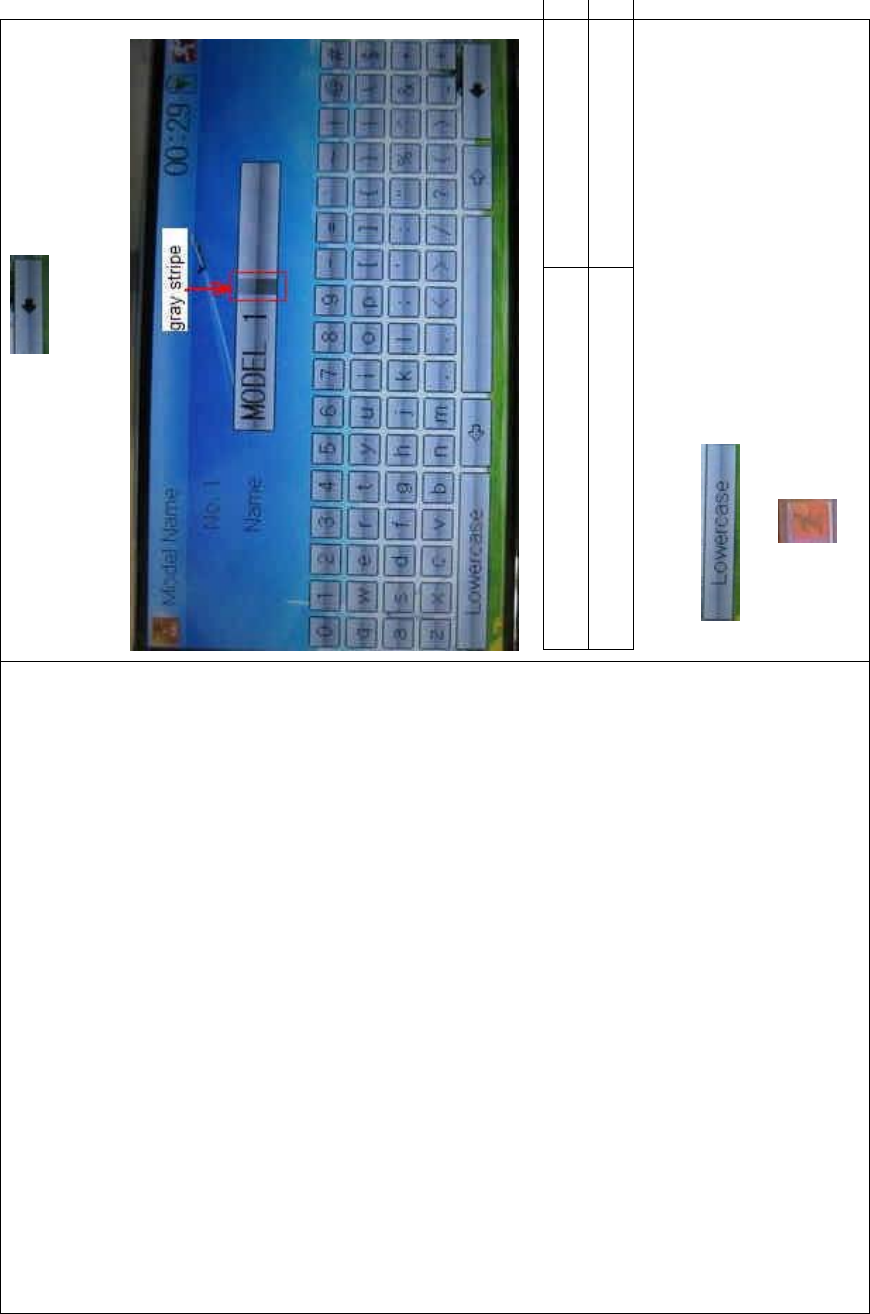
DEVO-8 Page no. Page 141 of 363
the frame. Touch the return key to clear up the old name.
English Your language
Gray stripe
Touch the soft keyboard to input a new name. It is possible to switch
between lowercase and uppercase by clicking the
key .
Then touch to exit.

DEVO-8 Page no. Page 142 of 363
2.3 Model copy
Touch the icon to enter Model Menu and click to
enter Model Copy.
Choose the model you want to be copied as source model. The serial
No. and model name of Source Model will be shown in the left side of
the interface.

DEVO-8 Page no. Page 143 of 363
Then touch the model in the right list where you want to locate the
source model. The serial No. and name of the model you chose are
shown under Dest Model in the lower left of interface as well as an
enquire “Are you sure?” is popped up.

DEVO-8 Page no. Page 144 of 363
Click OK to copy. Otherwise click Cancel. Then the interface will be
automatically returned to Model Menu. Click to save and exit.
2.4 Model copy
The model data between two DEVO-8 equipments can be wirelessly
copied via Model Transmit and Model Receive in Model Menu
A. Model transmission
Touch the icon to enter Model Menu and then continue to click
the icon to enter Model Transmit.

DEVO-8 Page no. Page 145 of 363
Choose the source model which will be transmitted. The serial No. and
name of the source model will be shown under Select Model in left side
of the interface as well as enquiry information “Are you sure?” in the
right side.
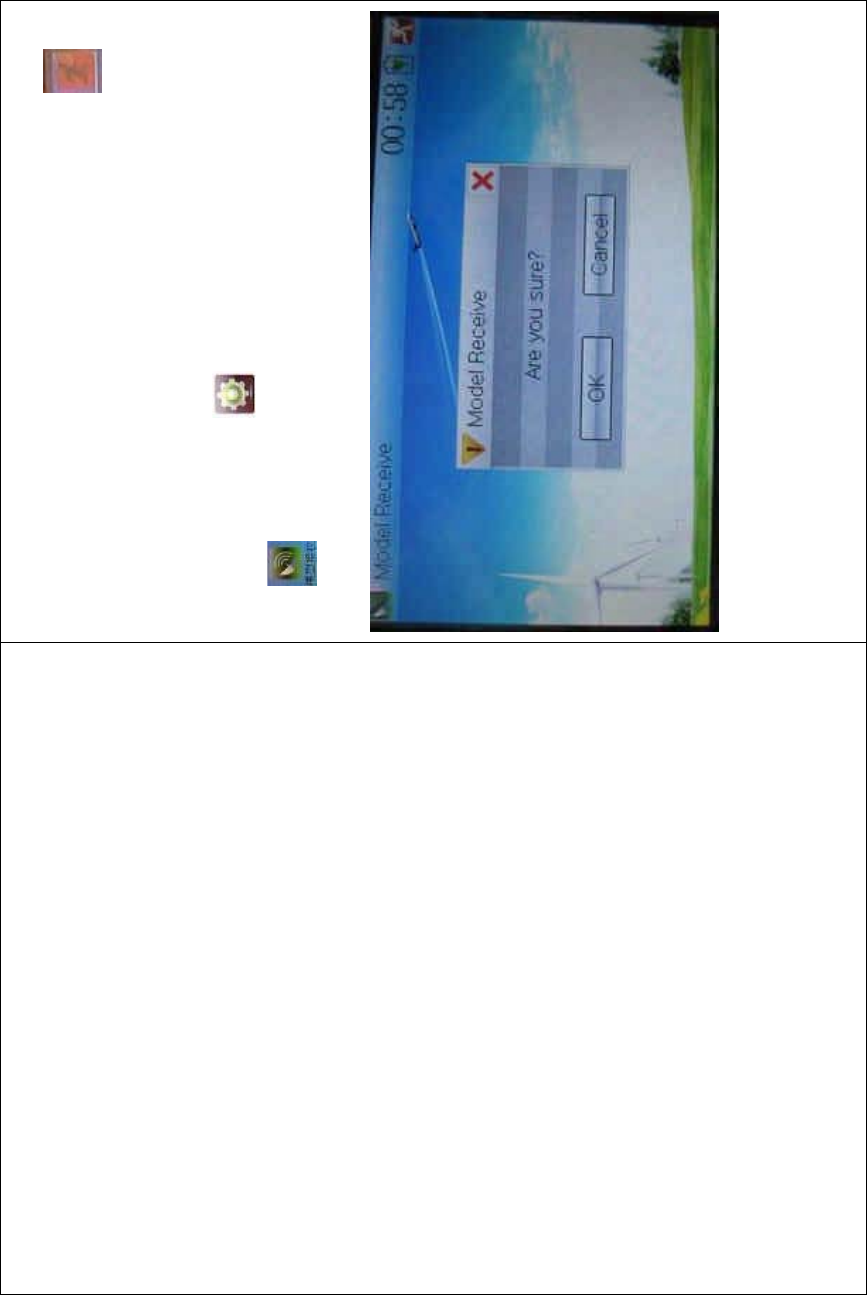
DEVO-8 Page no. Page 146 of 363
Click OK for transmission or Cancel for rejection. Enquiry information
“Transmitting ……” appears after clicking OK. Touch the icon to
exit.
B. Model receiving
Touch the shortcut icon to enter Model Menu and then touch the
icon to enter the MODEL RECEIVE INTERFACE. Enquiry
inf ormation “Are you s ure?” is s hown in the center of the interface.
Click Ok for receiving or Cancel for rejection. “Connecting ……” and
“Receiving ……” will be shown in series in the interface. The
information of “Received” with the model name will be shown in left side
after receiving is finished.

DEVO-8 Page no. Page 147 of 363
Choose the save position in the right name list by touching. Enquiry
information “Are you sure?” is shown after clicking the save position.
Click OK for save and the current interface will automatically return to
Mode Menu. Click Cancel for rejection.
Touch the icon to exit.
2.5 Model reset
All the model data can be restored to factory settings via Model Reset.
Touch the icon to enter Model Menu and then click

DEVO-8 Page no. Page 148 of 363
to enter Model Reset.
It is possible to store up to 60 models data in the model list of DEVO-8
equipment. There are two methods to reset the model data: batch reset
and single reset.
Method for batch reset:
Touch ‘All Models’ in Model Reset interface. Then ‘’All Models” and
enquiry “Are you sure?” appear in the left side. Click OK for reset, or
Cancel for rejection.
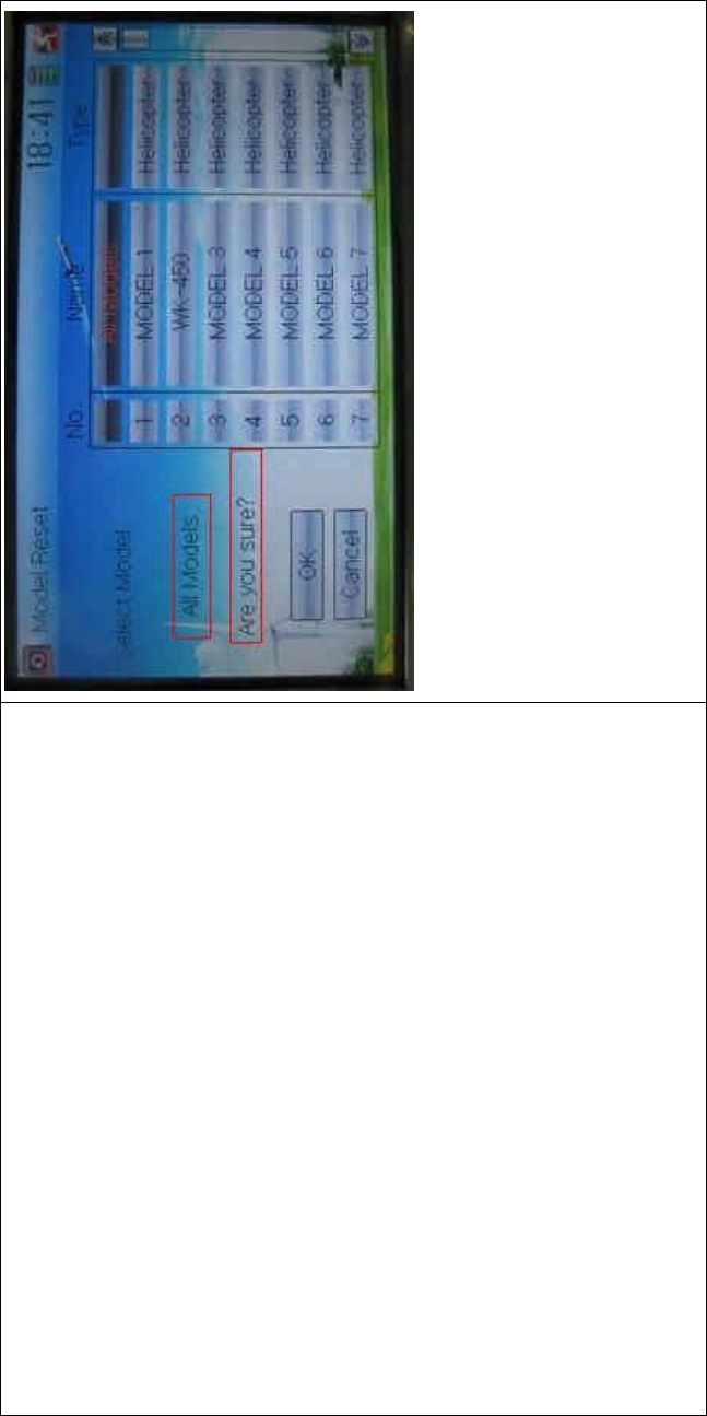
DEVO-8 Page no. Page 149 of 363
Method for single reset:
Touch the upper or lower navigation mark to move the scroll bar, and
then choose the model you want to restore in the model name list. The
selected model’s name and serial No., and an enquiry “It is in use! Are
you sure?” appear in the left side. Click OK for reset, or Cancel for
rejection.
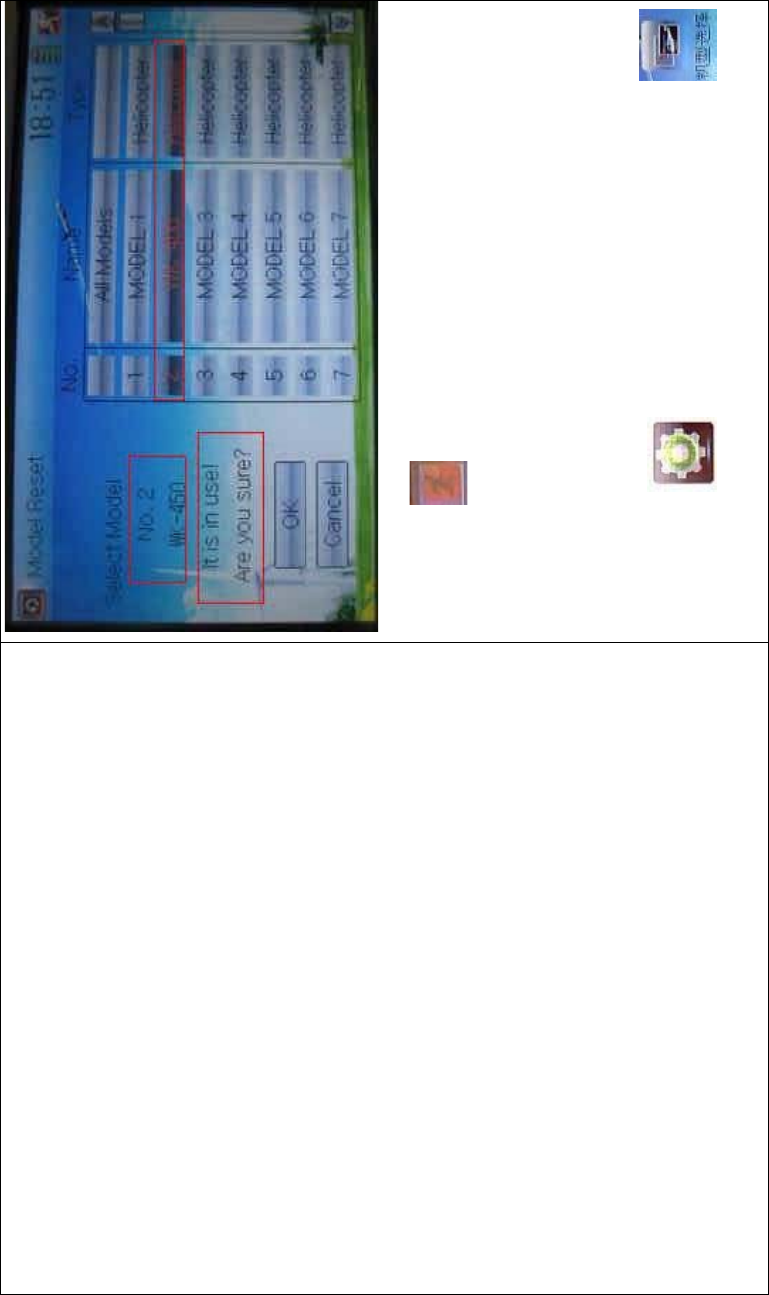
DEVO-8 Page no. Page 150 of 363
Click the icon to exit.
2.6 Type select
This device offers three model types menu. They are helicopter,
airplane, and glider, respectively.
Touch the icon to enter Model Menu and then click
to enter Type Select.
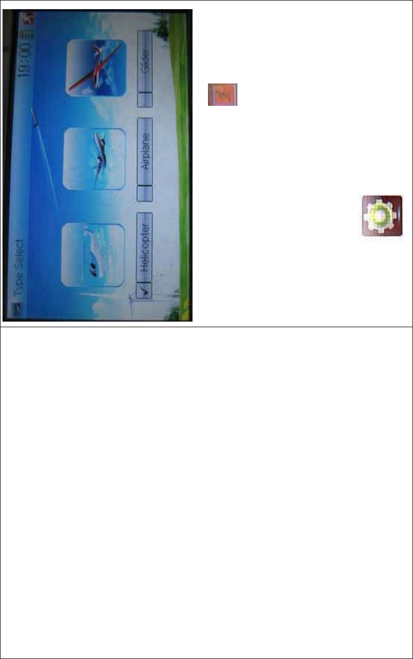
DEVO-8 Page no. Page 151 of 363
Choose the model type and then to uch the ico n to exit.
2.7 Trim system
Trim System is able to finely tune the following six items, respectively:
elevator, aileron, rudder, throttle, left trim, and right trim. The trim range
is covered from 1 to 20 grades (factory default is set at 4). It is
convenient to subtly modify the pitch by adjusting the trim range.
Touch the icon to enter Model Menu and then click
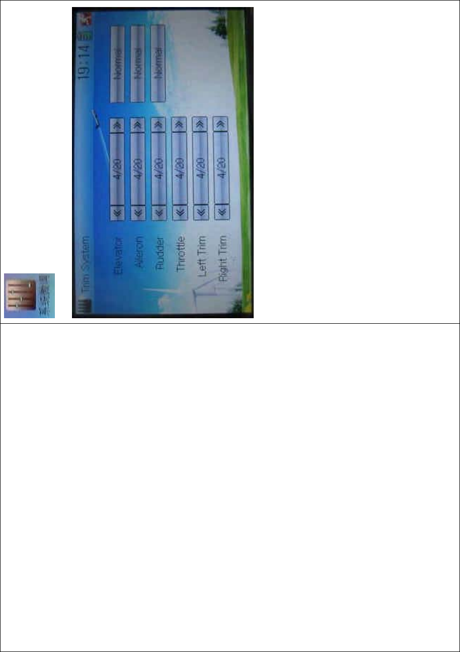
DEVO-8 Page no. Page 152 of 363
to enter Trim System.
Touch the corresponding navigatio n mark to change the trim value. The
bigger the trim value is, the bigger the trim range will be.
For elevator, aileron, and rudder, there are two more options: Normal
and Limited. “Normal” means the trim is always working although the
corresponding stick stays anywhere. “Limited” means the trim is out of
working when the corresponding stick is at maximum position.
2.8 Stick position
The stick can be used as a switch. Both the turn-on or turn-off positions,
at which the stick stays, can also be set up.
Method for setting:

DEVO-8 Page no. Page 153 of 363
Touch the icon to enter Model Menu and then click
to enter Stick Position Switch.
Click the navigation mark of Switch. It pops up a drop-down menu:
SPS0, SPS1, SPS2, and SPS3. Choose the switch you want to define.
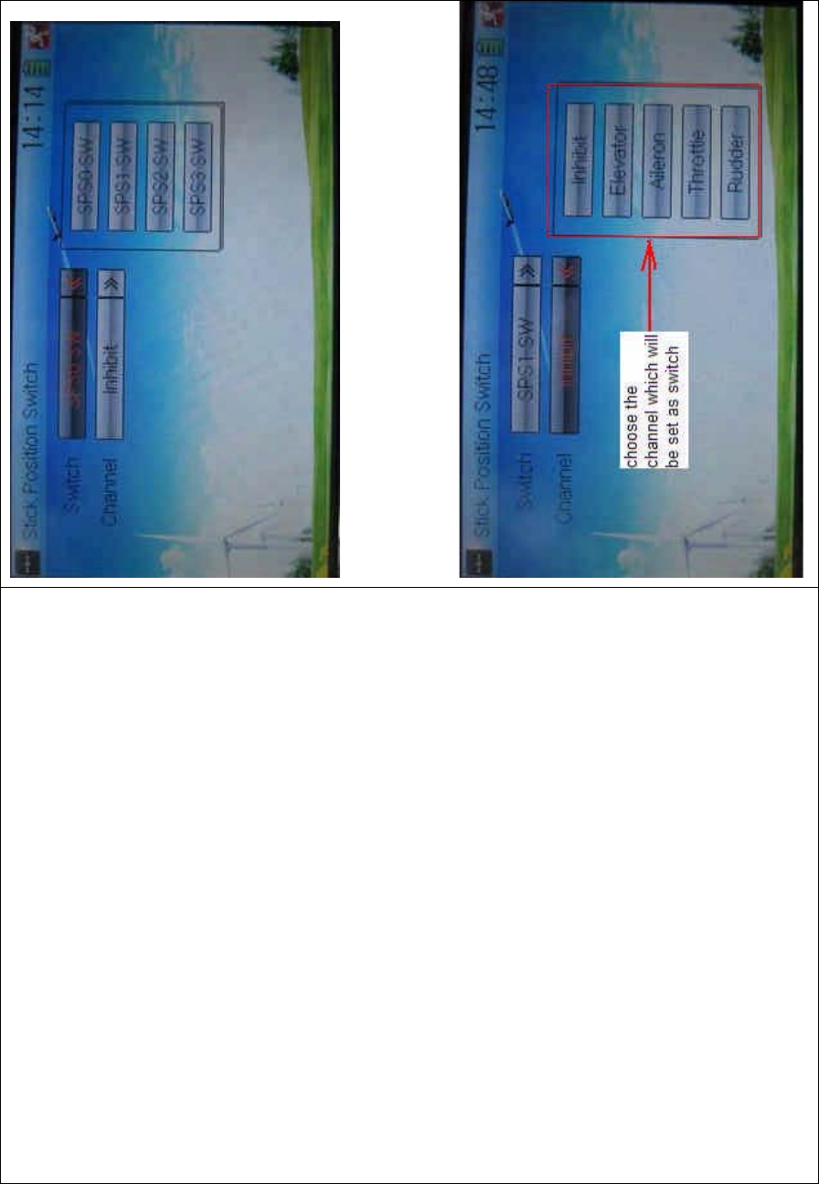
DEVO-8 Page no. Page 154 of 363
Then touch the navigation mark of Channel. It expands into five items:
Inhibit Elevator, Aileron, Throttle, and Rudder. The factory default
setting is Inhibit. C hoose the stic k you want to set as “switch”.

DEVO-8 Page no. Page 155 of 363
English Your language
Stick position switch
Switch
Channel
Inhibit
Elevator
Aileron
Throttle
Rudder
Choose the channel which will be set as
switch.
At the same time, “Position” and the status of turn-on or turn-off appear
under the item Channel. The current status of turn-on or turn-off will be
shown on the right top corner.
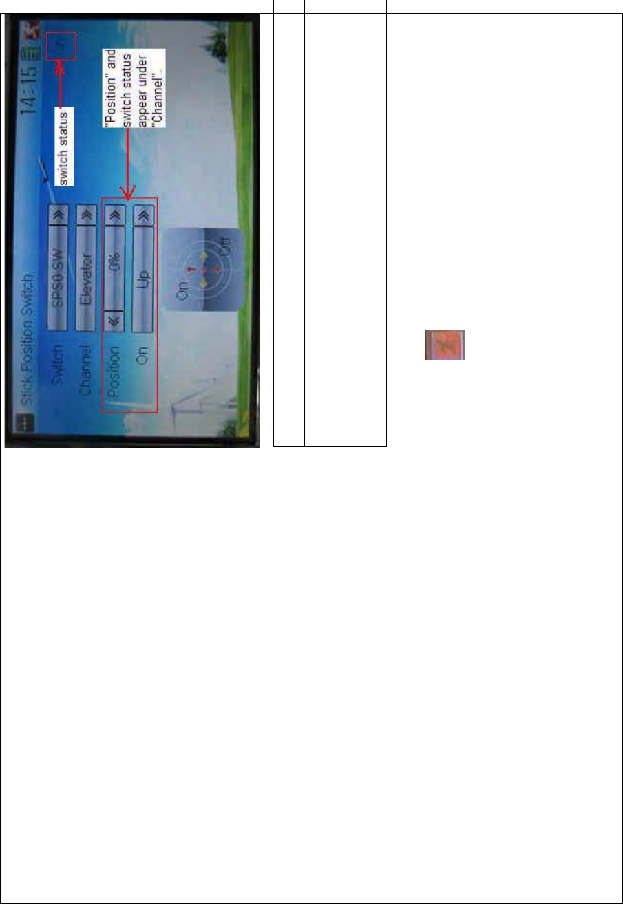
DEVO-8 Page no. Page 156 of 363
English Your language
Switch status
“Position” and switch status appear under
“Channel”
Click the icon to exit after the setting finished.
2.9 Warning
This function can set the warni ng f or unsafety of whic h stic k, switch
status, or flight mode stay at the position while turning on the device, or
is used as start-up warning in special purpose.
The factory default setting is Throttle Stick as Active, High direction at

DEVO-8 Page no. Page 157 of 363
10.0% Position, and warns while starting up.
To uc h t he i co n to enter Model Menu and then click
to enter the WARNING INTERFACE.
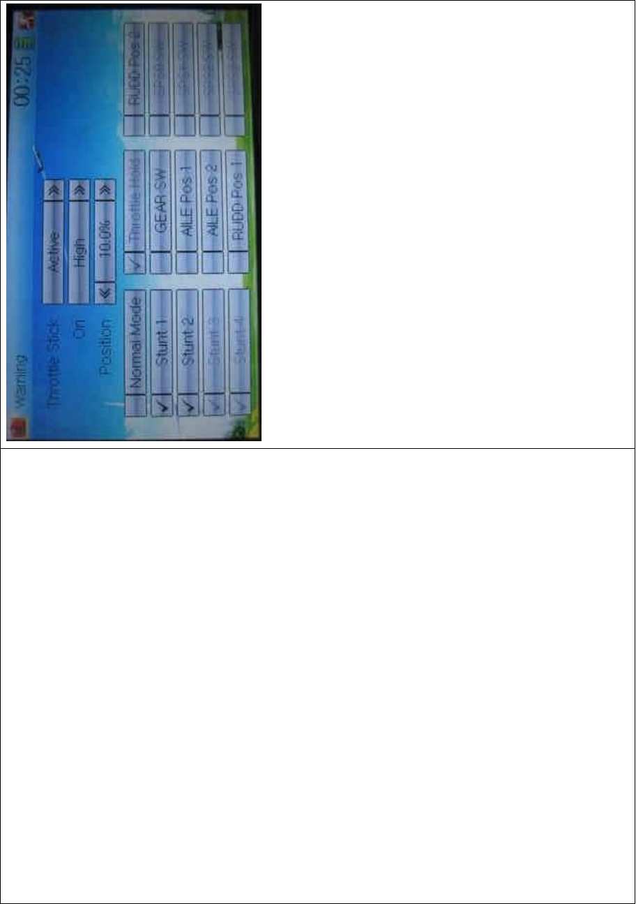
DEVO-8 Page no. Page 158 of 363
Setting method:
3) setting Throttle stick as warning
Click the navigation mark of Throttle Stick in the WARNING
INTERFACE.ItexpandsintoInhibitandActive.IfclickingInhibit,the
dropdown menu is retracted. If clicking Active, it will expand into On and
Position. The startup warning of throttle stick can be set at either high or
low position when startup is warning. Set the warning level by changing
the percentage in Position, whose setting value is ranged from 0.0 to
100.0%.
Take the right-hand throttle as an example. Warning position will be at
0.0% when the throttle stick is at the lowest position; Warning position
at 100.0% when the throttle stick is at the highest position. The factory
default setting is Throttle Stick is Active, Position in High direction at
10.0%.
4) setting other items

DEVO-8 Page no. Page 159 of 363
Other flight modes and switches warning will be shown in the
lower-middle part of the interface after the setting for throttle stick is
finished. Click the corresponding items you want to use.
Click to exit.
2.10 Device select
This setting can help you configure various functio nal switches, or
adjust levers according to your flight habits. It includes Flight Mode
MainSwitch,FlightModeExtraSwitch,FlightModeTrimSelect,
Throttle Hold Switch, Flap Switch Select, and Flap Trim Select.
Friendly reminder: This function is f requently uti lized i n flights.
Modelers will be greatly favored if expertly mastering its usage.
Setting method:
Touch the icon to enter Model Menu, and then click the
icon to enter Device Select.
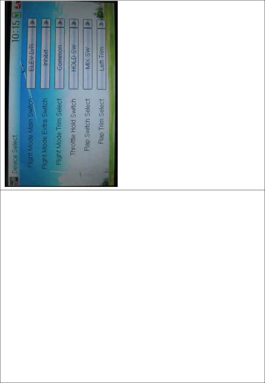
DEVO-8 Page no. Page 160 of 363
1) Flight Mode Main Switch
Touch the navigation mark of Flight Mode Main Switch to expand into a
dropdown menu. Choose the mode switch you desire. The factory
default setting is Inhibit.
2) Flight Mode Extra Switch
Flight Mode Main Switch should be previously activated before setting
this step. The setting method is same as “1) Flight Mode Main Switch”.
3) Flight Mode Trim Select
There are two modes: Common and Flight Mode. In Common mode all
the trim values, to which various sticks are relative, put equally effects
on all the flight modes.
In Flight Mode, the trim values to which each stick is relative put,
respectively, effect on the corresponding stick. The factory default is

DEVO-8 Page no. Page 161 of 363
Common.
4) Throttle Hold Switch
Refer to “1) Flight Mode Main Switch”.
5) Flap Switch Select
Refer to “1) Flight Mode Main Switch”.
6) Flap Trim Select
Refer to “1) Flight Mode Main Switch”.
2.11 Device Output
Device output is composed of eight items. It can set up output switches
and select the usage of levers, respectively. It can also activate, inhibit
or use other functions.
Friendly reminder: This function is frequently uti lized i n f lights.
Modelers will be greatly favored if expertly mastering its usage.
Setting method:
Touch the icon to enter Model Menu and then click
to enter Device Output.
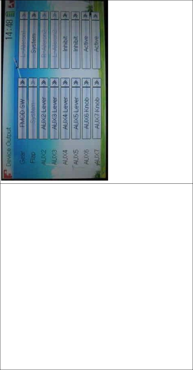
DEVO-8 Page no. Page 162 of 363
There are eight items to be adjustable. They are Gear, Flap, AUX2,
AUX3, AUX4, AUX5, AUX6, and AUX7. The setting methods for them
are shown below:
1) Gear
Touch the left column navigation mark of Gear and pop up an
expansion including FMOD SW, MIX SW, ELEV D/R, AILE D/R, RUDD
D/R, HOLD D/R, and GERA SW. Touch the desired item. The default
setting is GEAR SW.

DEVO-8 Page no. Page 163 of 363
English Your language
Touch navigation mark
Expansion of GEAR SW
Touch the right column navigation mark of Gear. Pop up an expansion
including Inhibit, Active, Gyro, Governor, and Pitch. Touch the desired
item. The default setting is Active.
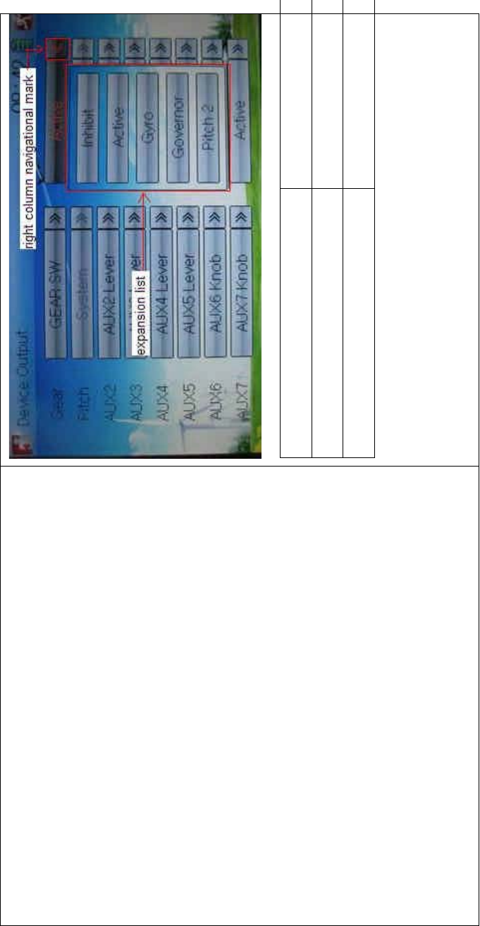
DEVO-8 Page no. Page 164 of 363
English Your language
Right column navigation mark
Expansion list
2) Flap
There will sho w the s witc h option o nly after the right column of Flap is
selected. Touch the right column of Flap and expand a dropdown menu
including Inhibit, Active, and System.
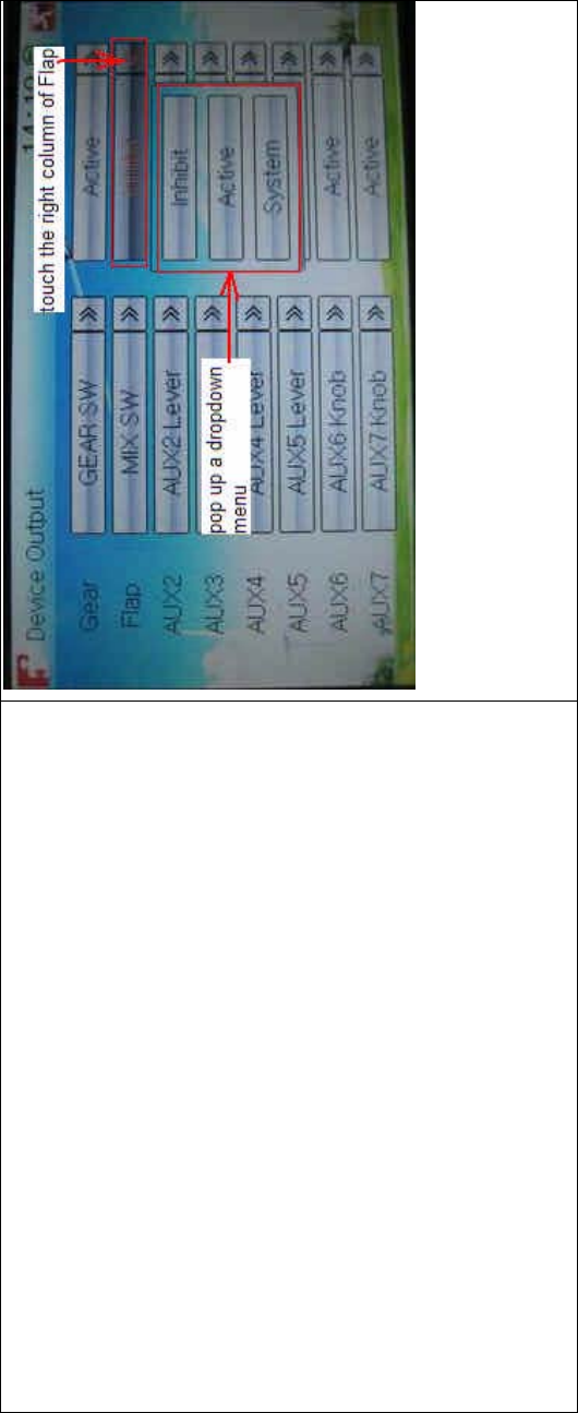
DEVO-8 Page no. Page 165 of 363
2.1) If choose Inhibit or Active, the expansion menu will include these
items: FMOD SW, MIX SW, ELEV D/R, AILE D/R, RUDD D/R, Left Trim,
and Right Trim. The default setting is Inhibit. Select the desired item as
theflapswitch.

DEVO-8 Page no. Page 166 of 363
2.2) If System is chosen, it is impossible to set in Flap.
3) AUX 2
Touch the left column navigation mark of AUX 2. Pop up an expansion
list including SPS0 SW, SPS1 SW, SPS2 SW, SPS3 SW, Left Trim,
Right Trim, and AUX2 Lever. Touch the desired item. The default setting
is AUX2 Lever.

DEVO-8 Page no. Page 167 of 363
Touch the right column navigation mark of AUX 2, and expands a list
including Inhibit, Active, Gyro, Governor, and Pitch 2. Click the desired
item. The default setting is Active.
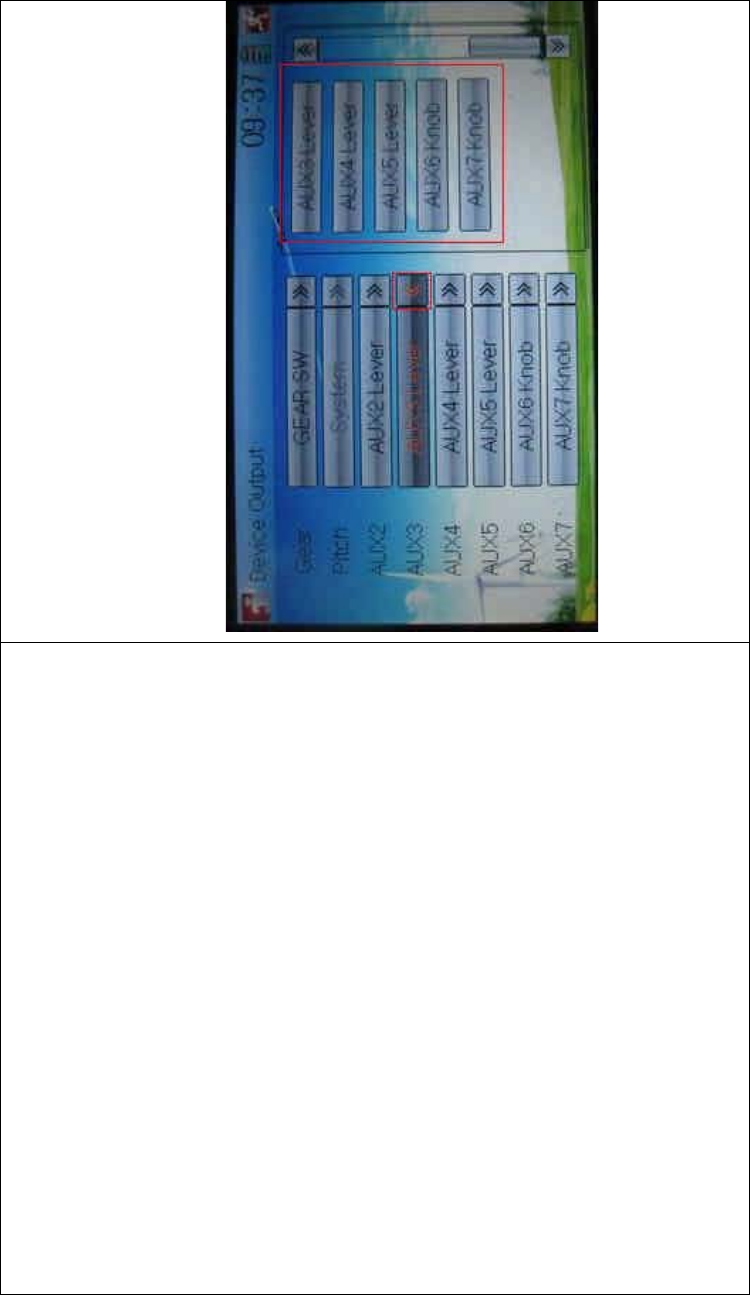
DEVO-8 Page no. Page 168 of 363
Then continue to set other items.
4) AUX 3
Touch the left column navigation mark of AUX 3, and expands a list
including AUX3 Lever, AUX4 Lever, AUX5 Lever, AUX6 Knob, AXU7
Knob. Touch the desired item. The factory default setting is AUX3
Lever.
Click the right column navigation mark of AUX3, and see an expansion
list including Inhibit, Active, Gyro, Governor, and Pitch 2. Choose the
desired item. The factory fault setting is Active. Then continue to set up
other items.
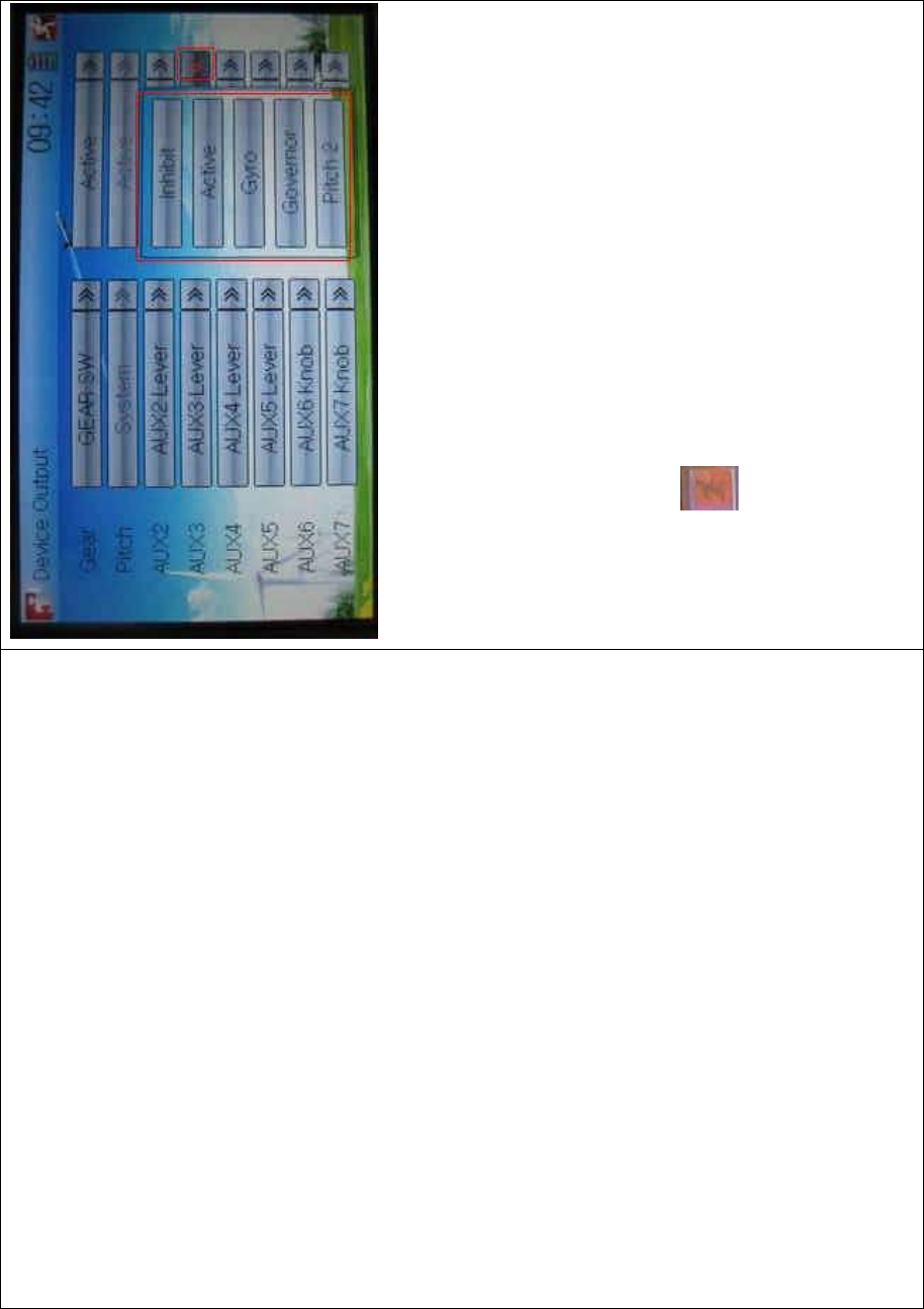
DEVO-8 Page no. Page 169 of 363
5) AUX 4
Refer to “4) AUX 4”.
6) AUX 5
Refer to “4) AUX 4”.
7) AXU6
Refer to “4) AUX 4”.
Click the icon to exit.
2.12 Wing type
Wing Type is grouped into Flaperon, DLETA, 4-Aileron, and V Tail.
Wing type selection:
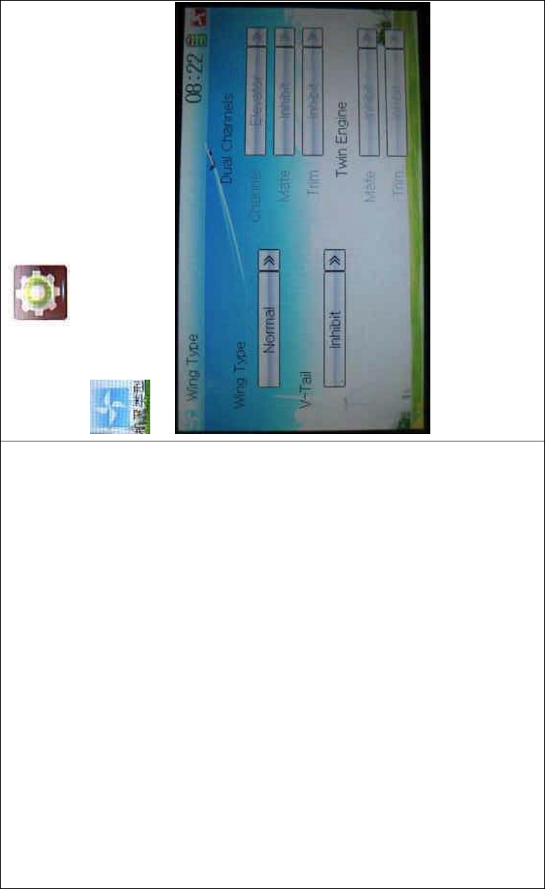
DEVO-8 Page no. Page 170 of 363
Touch the icon to enter Model Menu, and then touch
to enter the WING TYPE INTERFACE.
1) Flaperon
Touch the navigation mark of Wing Type and expand a dropdown menu
with Normal, Flaperon, DELTA, and 4-Aileron. Choose the desired wing
type.
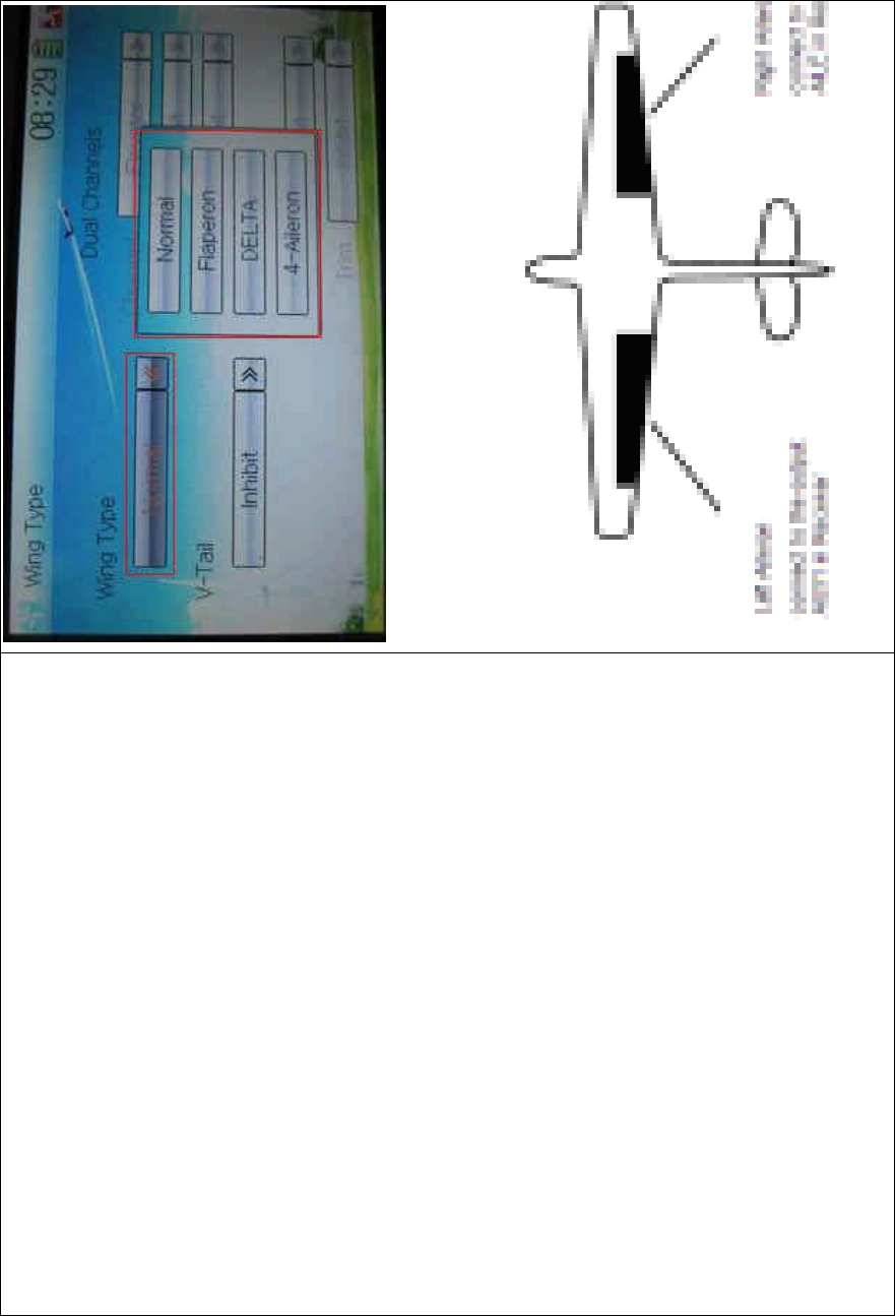
DEVO-8 Page no. Page 171 of 363
1.1) Flaperon
Below is the sketch map of Flaperon servos’ assignment:

DEVO-8 Page no. Page 172 of 363
English Your language
Left aileron
Right aileron
Connect to the o utput AUX1 in Receiver
Connect to the output AILE in Receiver
1.2) DELTA
Below is the sketch map of DELTA servo’s assignment:
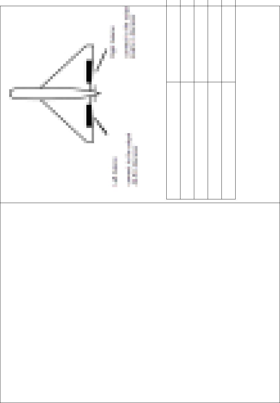
DEVO-8 Page no. Page 173 of 363
English Your language
Left Aileron
Right Aileron
Connect to the output AILE in Receiver
Connect to the output ELEV in Receiver
1.3) 4 Aileron
If your model airplane is equipped two left aileron servos and two right
aileron servos, we recommend you to use 4-Aileron function.
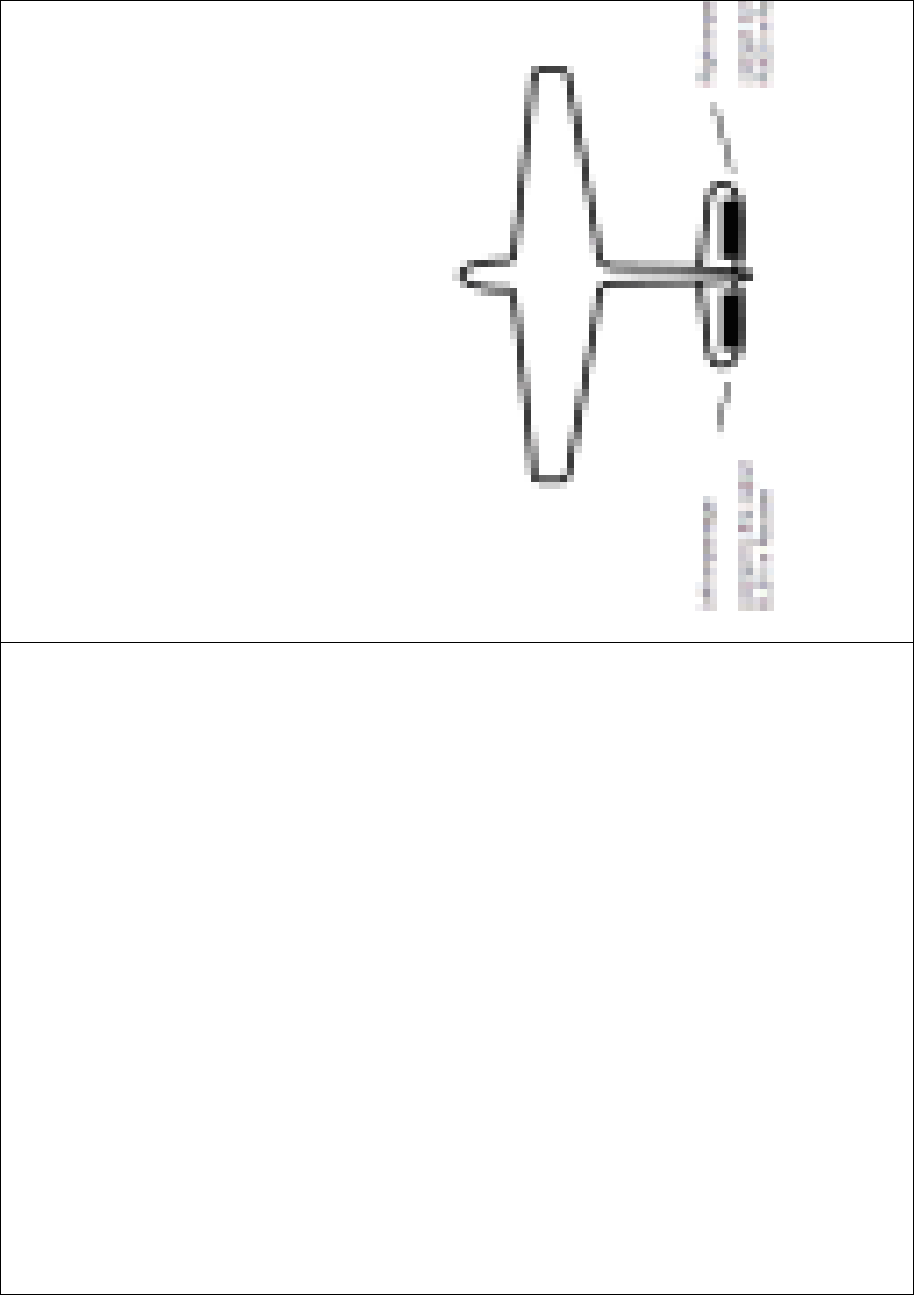
DEVO-8 Page no. Page 174 of 363
Touch the navigation mark of Wing Type, and expand a dropdown menu
with Normal, Flaperon, DELTA, and 4-Aileron. Click 4-Aileron. Check
the channel assignment by touching Monitor (Refer to “3.19 Monitor”).
TheleftaileronservosshouldbeconnectedtotheoutputsGERAand
AUX3 in the receiver, and the right aileron servos connected to AILE
and GYRO in the receiver.
All the servos’ parameters can be adjusted, respectively.
2) V-TAIL
Touch the navigatio n mark of V-TAIL and expand a dropdown menu with
Inhibit and Active. Choose Active.
Below is the sketch map of V-tail servos’ assignment:

DEVO-8 Page no. Page 175 of 363
English Your language
Left empennage
Right empennage
Connect to the output ELEV in Receiver
Connect to the output RUDD in Receiver
3) Dual channels setting
Dual Channels can be set as Elevator, Aileron, Rudder, or Flaperon. It
is of dual channel output function. The channel, which will be set as
dual channel at AUX in Device Output (Refer to “2.11 Device Output”),
should be previously set as Inhibit when the AUX channel is being set.
Setting method:
3.1) Channel selection:
Touch the navigation mark of Channel in the interface of Wing Type,
and expand into Elevator, Aileron, Rudder, and Flap. We take Elevator
as an example.
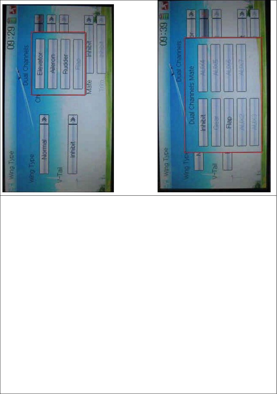
DEVO-8 Page no. Page 176 of 363
3.2) Mate setting
Click the navigation mark of Mate and expand a dropdown menu with
Inhibit, Gear, Flap, AUX2, AUX3, AUX4, AXU5, AXU6, and AUX7.

DEVO-8 Page no. Page 177 of 363
Touch the desired channel in black. The channel, whose characters are
shown in gray, has being applied.
3.3) Trim setting
Click the navigation mark of Trim and expand a submenu with Inhibit,
Left Trim, Right Trim, AUX2 Lever, AUX3 Lever, AUX4 Lever, AUX5
Lever, AUX6 Knob, and AUX7 Knob. Choose the item that you want to
select as trim lever.
3.4) the settings for Aileron, Rudder, and Flap in the item Channel are
same as above.
4) Twin Engine
This function can be set as twin engine output to meet the requirement
for the models, which are powered by twin engines.
4.1) Mate setting
Click the navigation mark of Mate and expand a dropdown menu with
Inhibit and the inhibited channels previously set in “2.11 Device Output”.
Choose the desired channel in black. These channels in gray are not
available.
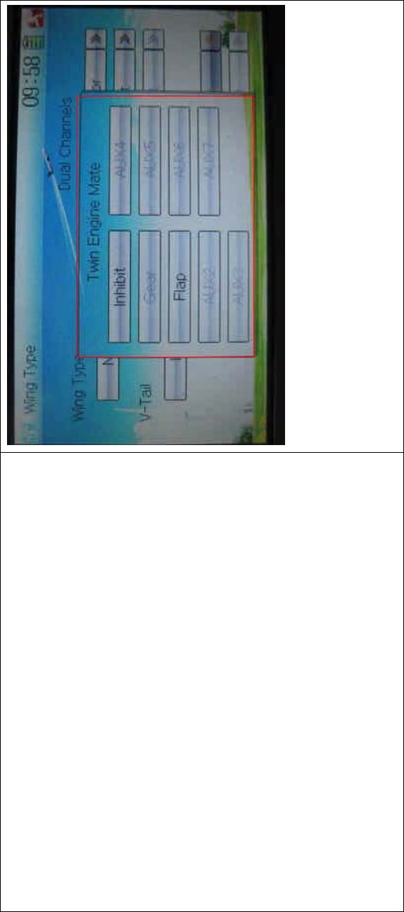
DEVO-8 Page no. Page 178 of 363
4.2) Trim setting
Click the navigation mark of Trim and expand into Inhibit, Left Trim,
Right Trim, AUX2 Lever, AUX3 Lever, AUX4 Lever, AUX5 Lever, AUX6
Knob, and AUX7 Knob.
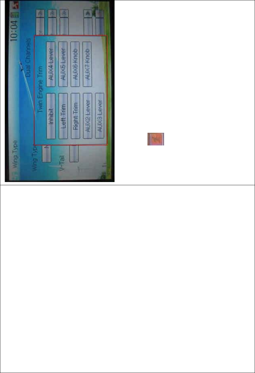
DEVO-8 Page no. Page 179 of 363
Touch the item which you want to set as the trim lever or knob for twin
engines.
Click the icon to exit after finished.
2.13 Fixed ID
This setting will bind DEVO-8 and its receiver in a unique corresponding
relationship. It will greatly speed up the time of automatic binding when
DEVO-8 powered on.
1) Setting for fixed ID
The setting for fixed ID should be under the status that automatic ID
binding is successfully finished. Below is the setting method.
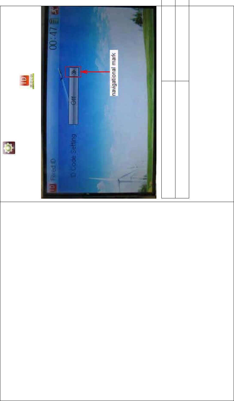
DEVO-8 Page no. Page 180 of 363
Touch the icon to enter Model Menu in the main interface, and
then enter Fixed ID by touching the icon in Model Menu.
English Your language
Navigation mark
Touch the navigation mark of the item ID Code Setting. It will expand
into two statuses: Off and On. A series of random digits will be shown
below after touching On.
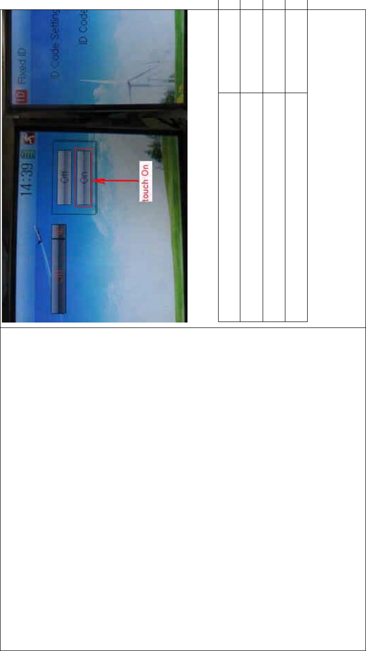
DEVO-8 Page no. Page 181 of 363
English Your language
To uc h “O n”
A series of random digits is shown here
A mini soft keyboard is shown in t he lower part after touc hi ng the
random digits of ID Code

DEVO-8 Page no. Page 182 of 363
English Your language
Mini soft keyboard
The new ID digits can be modified by touching the mini soft keyboard.
Touch Match after the new ID is already set. An enquiry interface of “Are
you sure?” pop up. “ID Code Match … …” will be shown after touching
OK.
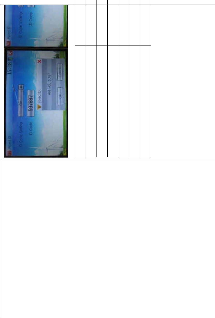
DEVO-8 Page no. Page 183 of 363
English Your language
ID Code Setting
ID Code
Fixed ID
Are you sure?
Cancelled
ID Code Match
2) Fixed ID cancellation
Insert the assorted BIND PLUG into the output terminal of BATT before
the receiver is powered on, and then plug 5V DC power into other
output terminal. The red light of receiver will flash slowly. This means
the fixed ID code has been cancelled. Pull out BIND PLUG.
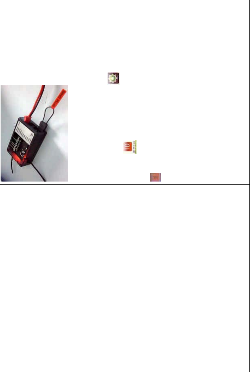
DEVO-8 Page no. Page 184 of 363
DEVO-8 also needs to make relative cancellation and reversion after
the fixed ID in receiver is cleared out.
In the mai n interface touch the icon to enter Model Menu and
then touch to enter Fixed ID. Touch ID Code Setting to expand
the navigation mark into two statues On and Off. Touch Off. Then touch
to exit.
3.0 Function Menu
Function Menu is used to make personalizedly fine adjustment to the
selected models. It includes Reverse Switch, Travel Adjust, Sub Trim,
Dual Rate and Exponential, Throttle Hold, Throttle Curve, Snap Roll,
Differential setting, Balance setting, Gyro Sensor, Governor, Aileron to
Rudder Mix, Elevator to Flap Mix, Rudder to Aileron/ Elevator Mix, Flap
System, Aileron to Flaperon Mix, Pitch Curve, Program Mix, Monitor,
Fail Safe, Trainer, and Timer.
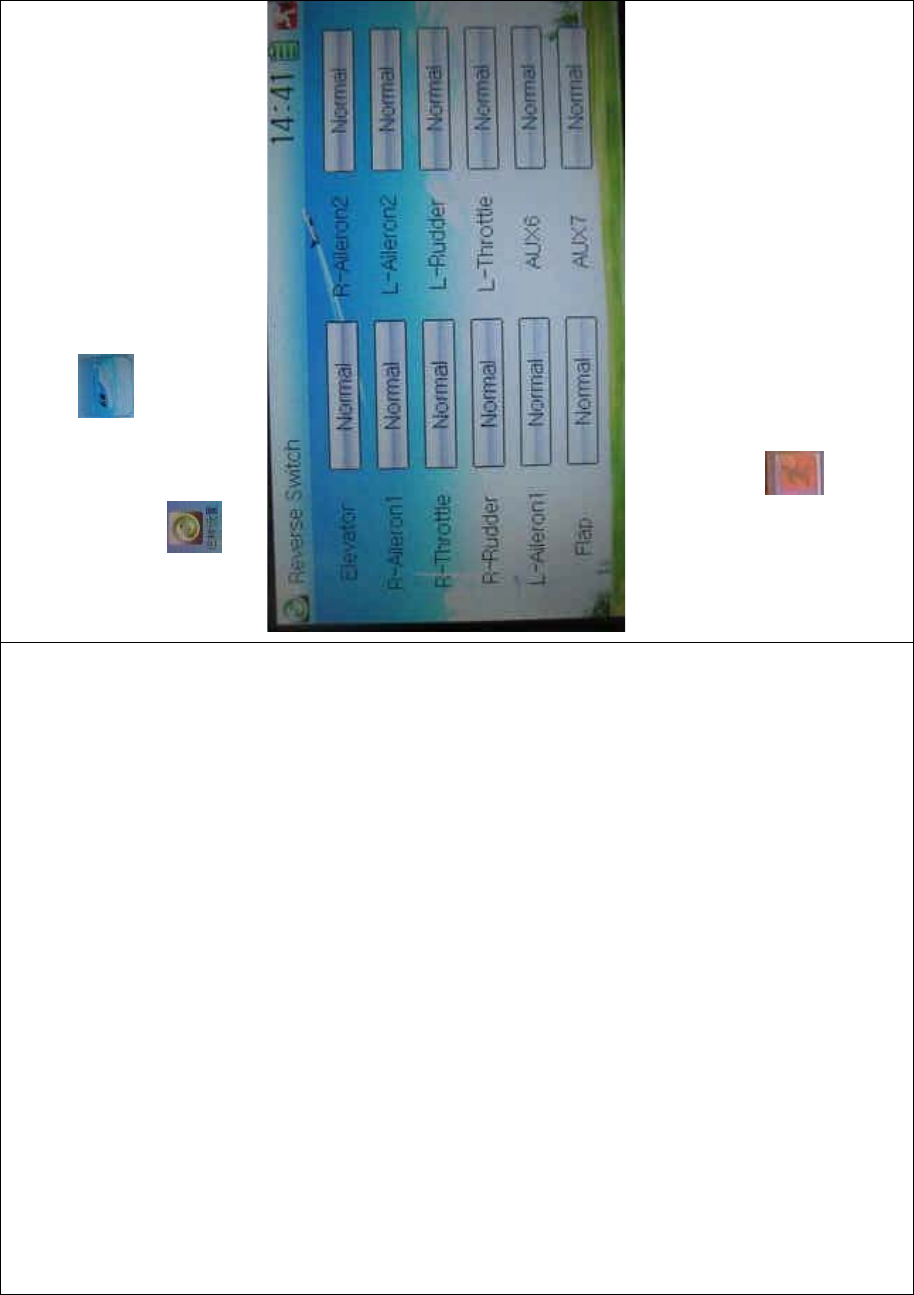
DEVO-8 Page no. Page 185 of 363
3.1 Reverse switch
Touch the shortcut icon to enter Function Menu, and then click
the icon to enter the REVERSE SWITCH INTERFACE.
There show all the reverse switches’ statuses of twelve channels. Touch
the desired item to reverse its current status. The status includes two
types: Normal and Reverse. The default setting is Normal.
Touch the icon to exit after finished.
3.2 Travel adjust
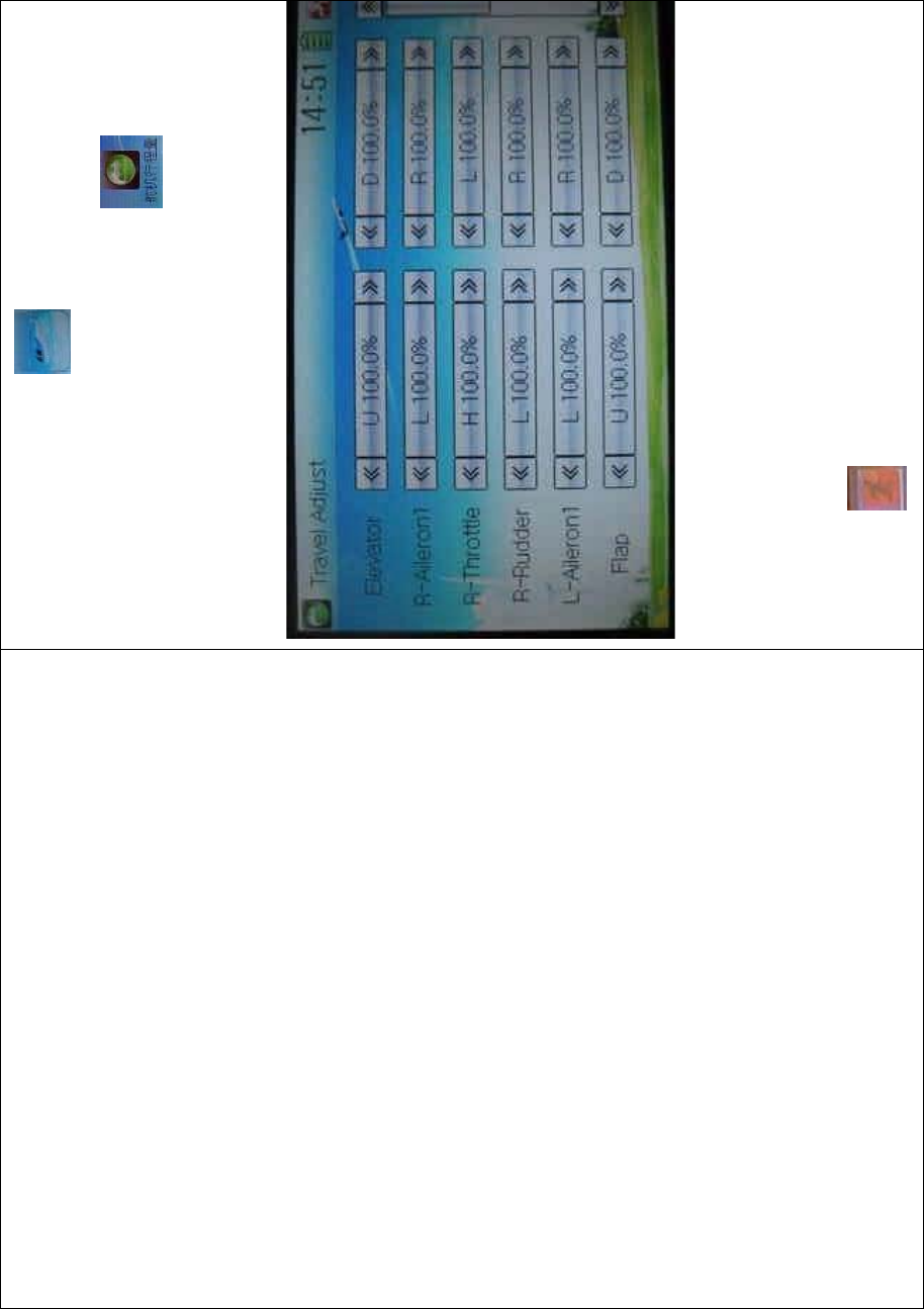
DEVO-8 Page no. Page 186 of 363
Touch the icon to enter Function
Menu and then click the icon to enter
the SERVO TRAVEL ADJUST INTERFACE.
The interface contents two pages to show the current travel status of all
the twelve channels. Touch the navigation mark of each item to
increase or decrease corresponding travel adjustment amount. The
adjustable range is 0.0-150.0%. The default setting is 100.0%.
Click the icon to exit after finished.
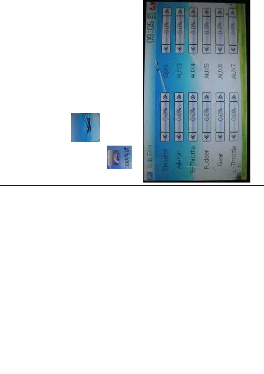
DEVO-8 Page no. Page 187 of 363
3.3 Sub trim
Sub Trim is used to make parallel movement of servos. It is
recommended to adjust the servo bell crank if the servo is far away from
its neutral point. The excessive usage of sub trim may damage the
servo.
Setting method:
To uc h t he i co n to enter Function Menu and then click the
icon to enter the SUB TRIM INTERFACE.
Touch the navigation mark of the desired item to adjust the amount for

DEVO-8 Page no. Page 188 of 363
rectifying the servo’s neutral point. The default neutral point is set at
0.0%. The adjustment range of each channel is shown as below:
English Your language English Your la
Channel name Adjustment range
Right elevator D62.5%-U62.5%
Right aileron 1 R62.5%-L62.5%
Throttle L62.5%-H62.5%
Rudder R62.5%-L62.5%
Left aileron 1 R62.5%- L62.5%
Flap D62.5%- U62.5%
Right aileron 2 R62.5%- L62.5%
Left aileron 2 R62.5%- L62.5%
AUX4 -62.5%- +62.5%
AUX5 -62.5%- +62.5%
Left elevator D62.5%- U62.5%
AUX7 -62.5%- +62.5%
Note: the model names shown will be different with the selected
channels different.
Click the icon to exit after finished.
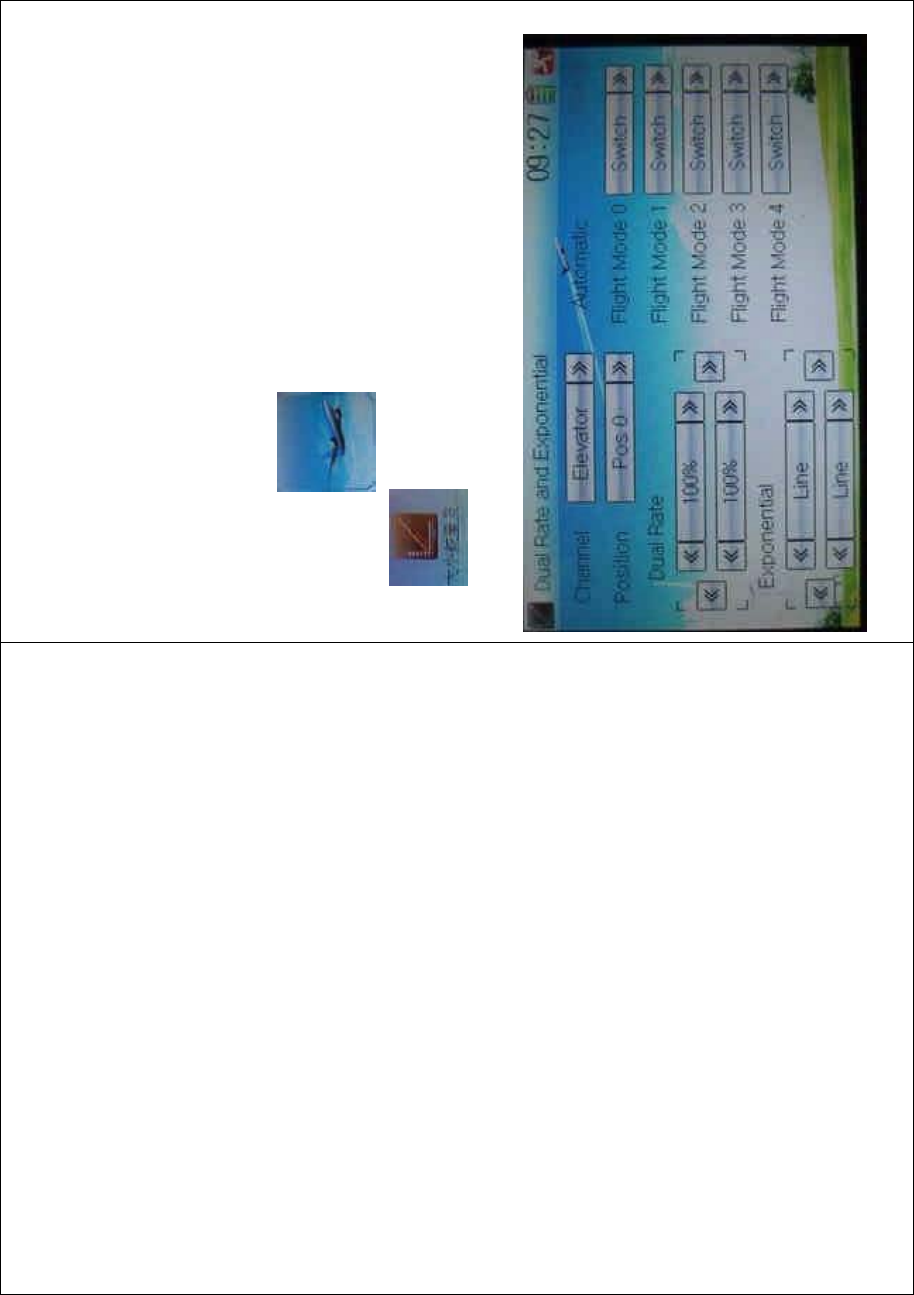
DEVO-8 Page no. Page 189 of 363
3.4 Dual rate and exponential
It is possible to use D/R switch to control over the dual rate of elevator,
aileron, and rudder after the function of Dual Rate and Exponential is
set up. The setting range is 0-125%. Under the help with exponential
curve adjustment, it is not only manually but also automatically able to
set up various parameters which are suitable for yourself.
Setting method:
To uc h t he i co n to enter Function Menu and then click the
icon to enter the DUAL RATE AND EXPONENTIAL
INTERFACE.
1) Channel selection
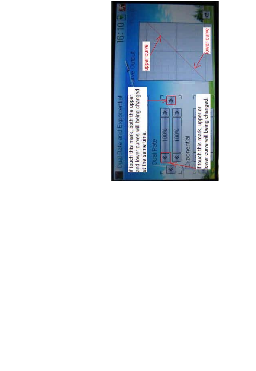
DEVO-8 Page no. Page 190 of 363
Touch the navigation mark of Channel and expand a selectable list
including Elevator, Aileron, and Rudder. Click the desired channel which
will be shown in Channel.
2) Position selection
Touch the navigation mark of Position and expand a selectable list
including Pos 0, Pos 1, Pos 2, Pos 3, and Pos 4. Click the desired item
which will be shown in Position. But there will only show Pos 0, Pos 1,
and Pos 2 in manual setting.
3) Dual Rate adjustment
Itispossibletomodifythevaluebytouchingthenavigationmarkof
Dual Rate.
If touchi ng the navigatio n mark for just one item to amend the dual rate
value, the dual rate of the correspondi ng servo wi ll be changed in one
direction, while the curve will being changed in one direction at the right
graph.

DEVO-8 Page no. Page 191 of 363
If touching the navigation mark for both items to amend the dual rate
value, the dual rate of the corresponding servo will be changed while
the curve will being changed at the same time, shown at the right graph.
The default setting is 100%.
English Your language
Upper curve
Lower curve
If touch this mark, both the upper and
lower curves will being c hanged at t he
same time.
If touch this mark, either upper or lower
curve will being changed.
4) Expo nential adjustment
It is possible to adjust the exponential output value of the servo at that
point, which is set up in step “2) Position selection”, by touching the
navigation mark of Exponential.
DEVO-8 Page no. Page 192 of 363
If touchi ng the navigatio n mark for just one item to amend the dual rate
value, the dual rate of the correspondi ng servo wi ll be changed in one
direction, while the curve will being changed in one direction at the right
graph.
If touching the navigation mark for both items to amend the dual rate
value, the dual rate of the corresponding servo will be changed while
the curve will being changed at the same time, shown at the right graph.
The default setting is Line.
Then to uc h this mark to return to the interface of Dual Rate and
Exponential.
5) Automatic setting
Under working with Flight Mode, it is possible to switch between the
dual rate and exponential, which are set in above 3) Dual Rate
adjustment and 4) Exponential adjustment, respectively.
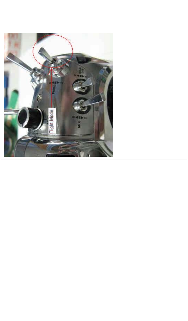
DEVO-8 Page no. Page 193 of 363
The settings for Flight Mode 0, Flight Mode 1, Flight Mode 2, Flight
Mode 3, and Flight Mode 4 are available.
Note: Before using the function of automatic setting, both Flight Mode
Main Switch and Flight Mode Extra Switch should be previously set as
relative switches. Refer to “2.10 Device Select”.
Touch the flight mode that you want to set as automatic operation, and
an expansion list will be shown. Click the desired position. If Switch is
selected, it is only controlled by the corresponding dual rate lever.
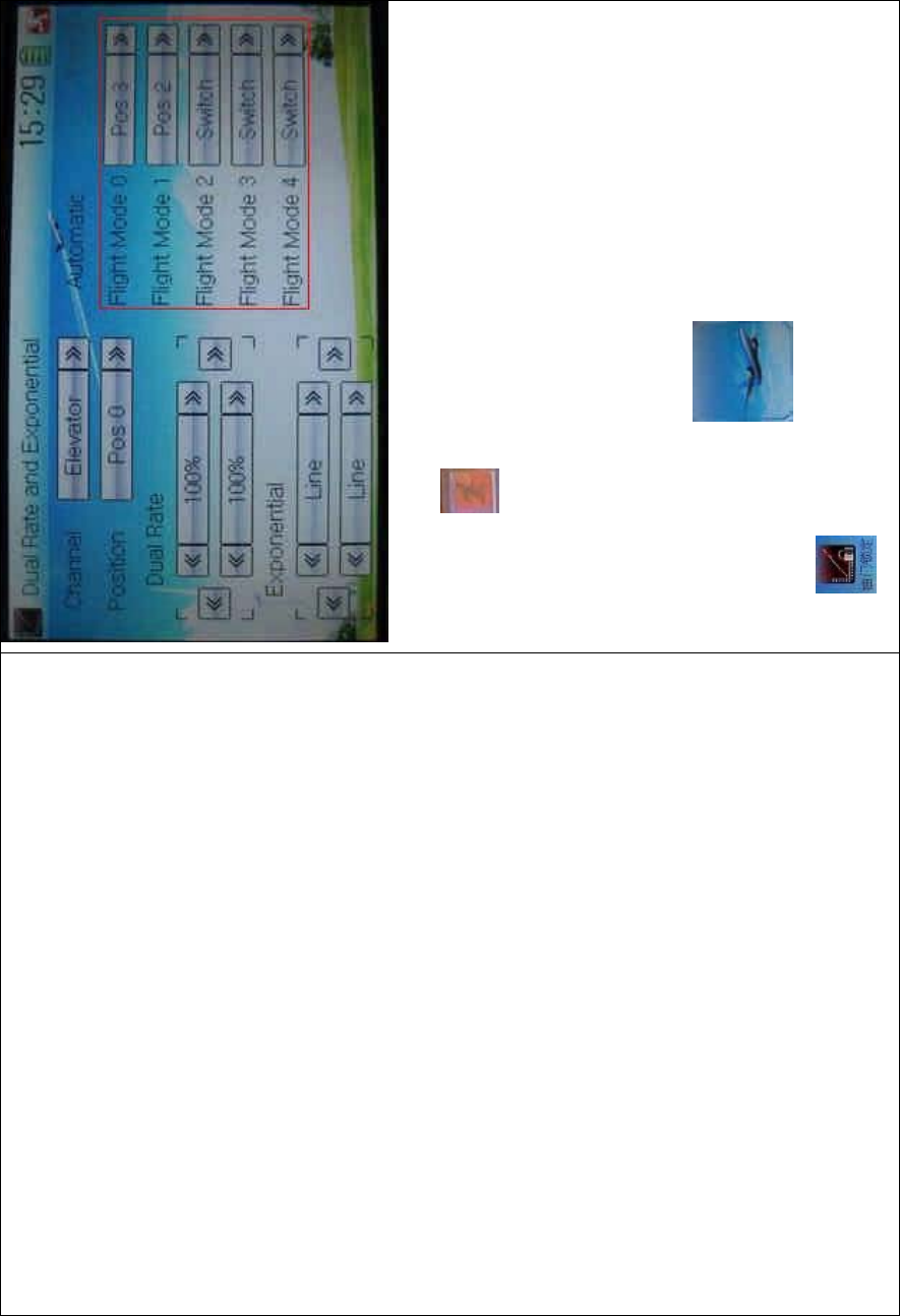
DEVO-8 Page no. Page 194 of 363
Click the icon to exit.
3.5 Throttle hold
If this function is set, the switch will be executed by hold switch. The
settingvalueofthrottleholdisrangedfrom-20.0to50.0.
Setting method:
Touch the shortc ut icon to enter Function Menu, and then
click to enter the THROTTLE HOLD INTERFACE.
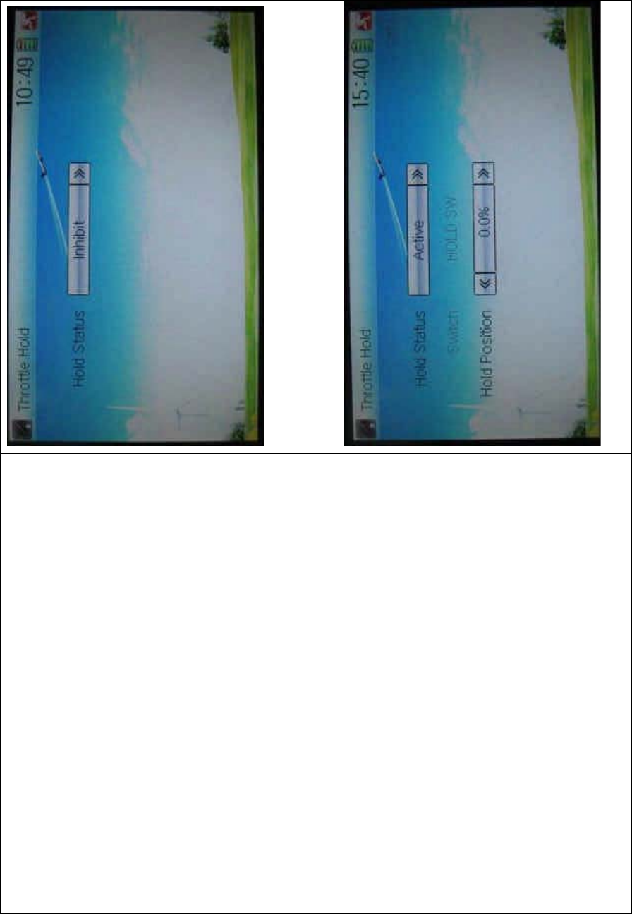
DEVO-8 Page no. Page 195 of 363
Touch the navigation mark of Hold Status, and an expansion list will be
shown as Inhibit and Active. Click Active, there appear Switch, and Hold
Position in the following interface.
vv

DEVO-8 Page no. Page 196 of 363
1) Setting for Switch
This item is impossible to be set. The default setting is HOLD SW.
2) Setting for Hold Position
Touch the left navigation mark of the item Hold Position to decrease the
position amo unt, whose mi ni mum is -20.0%; touch the right to increase
the position amount whose maximum is +50.0%.
Click the icon to exit after all the settings are finished.
3.6 Throttle curve
Throttlecurvesareadjustedthroughninepoints,whichofalltheflight
modes can be respectively set. The left and right throttles can be
separately set after it is previously set as dual engines. Refer to Twin
Engine at “2.12 Wing Type”
Setting method:
To uc h t he i co n to enter Function Menu and then click the
icon to enter the THROTTLE CURVE INTERFACE.A
dropdown menu with “All Servos Hold?” pops up.
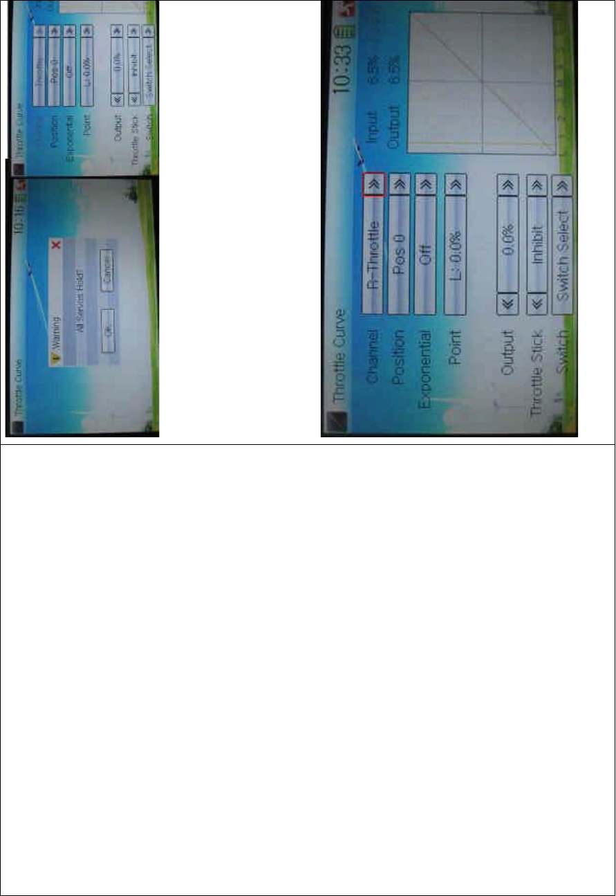
DEVO-8 Page no. Page 197 of 363
Click OK for all the servos locked at the current statuses. Click Cancel
for all the servos unlocked.
1) Channel setting
After previously set up Twin E ngine, touch the navigation mark of
Channel and expand a list including Left Throttle and Right Throttle.
Select the desired throttle which will be shown in Channel. Channel will
be shown in grey if Twin Engine is not previously selected.
2) Position selection
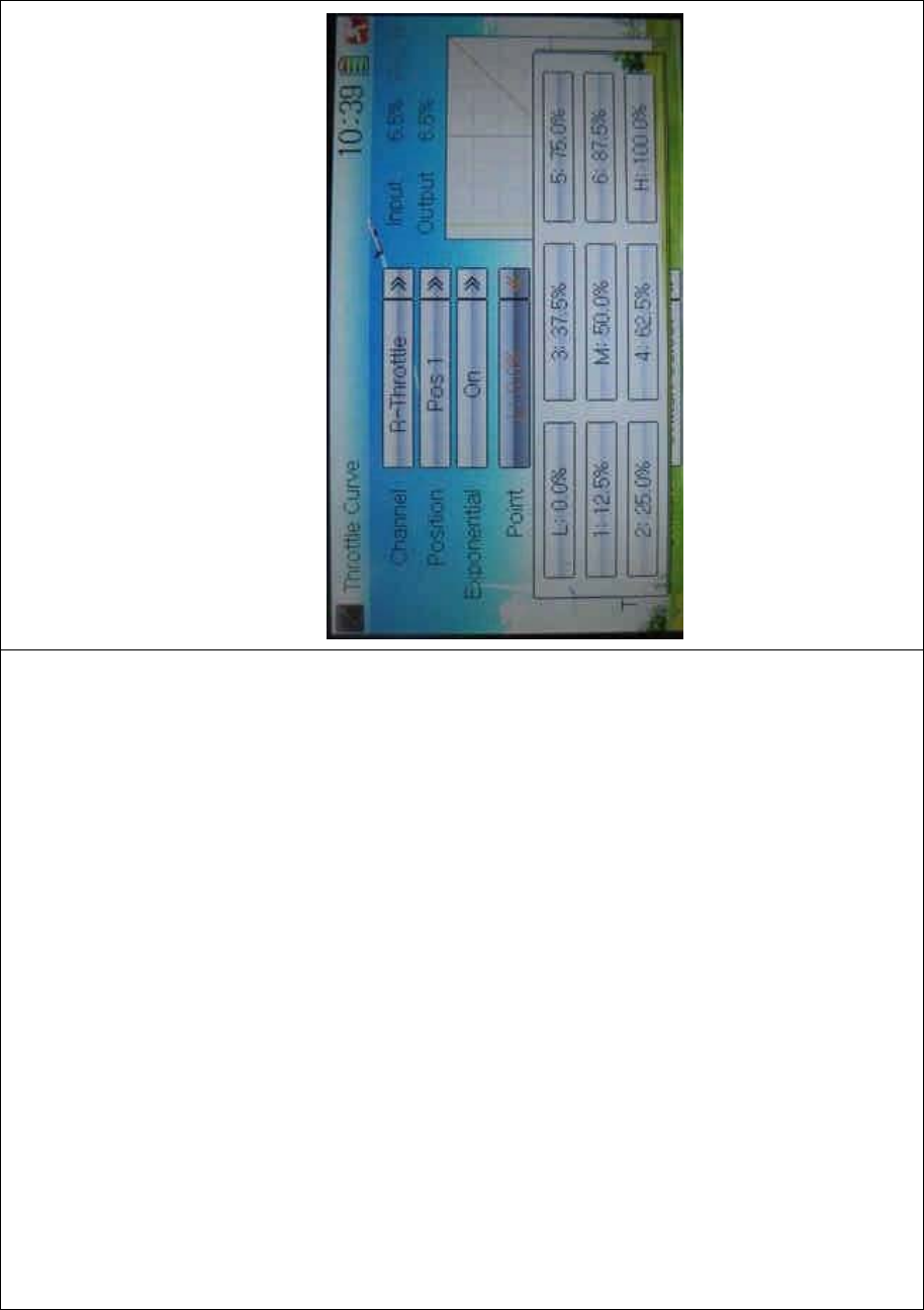
DEVO-8 Page no. Page 198 of 363
Touch the navigatio n mark of Position and expand a list with Pos 0 and
Pos 1. select the item you want to set.
3) Exponential setti ng
Touch the navigation mark of Exponential and expand a list with Off and
On. The throttle curve will being changed smoothly if clicking On.
4) Point setting
Touch the navigatio n mark of Point and expand a list includi ng ni ne
points. Select the point you want to adjust.
5) Status setting
Touch the navigation mark of Status and expand a list with Inhibit and
Active. Click Inhibit for keeping the current value (the default setting is
Inhibit); c lic k Active for changi ng t he above point’s value. A nother item
Output will be shown below after choosing Active.
6) Output setting
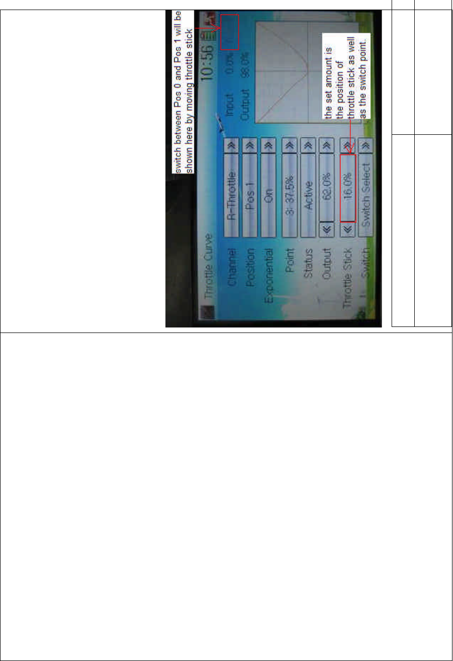
DEVO-8 Page no. Page 199 of 363
Touch the left or right navigation mark of Output to decrease or
increase, respectively, the output value. The adjustable range is from
0.0% to 100.0%.
7) Throttle setting
Touch the left or right navigation mark of Throttle Stick to decrease or
increase, respectively, the amount with a lower limit of 0.0% and an
upper limit of 100.0%. The default setting is Inhibit.
The switch between Pos 1 and Pos 0 can be freely realized through
throttle stick after the above amount has been set up.
English Your language
Switch between Pos 0 and Pos 1 will be
shownherebymovingthrottlestick.
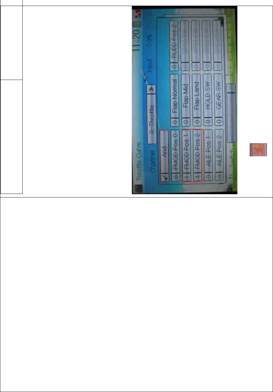
DEVO-8 Page no. Page 200 of 363
The set amount is the position of throttle
stick as well as the switch point.
The above set amount is the position of throttle stick as well as the
switch point.
8) Switch selection
When the item Throttle Stick is set in Inhibit, it is possible to switch
between Pos 0 and Pos 1 by Switch.
Touch the navigation mark of Switch and expand a dropdown menu
including the selectable items in black. Select the desired item whose
left side will be changed into “1” from “0”. If two items are selected, the
item And should be chosen. Then touch the navigation mark of Switch
to return back.
Click the icon to exit after finished.
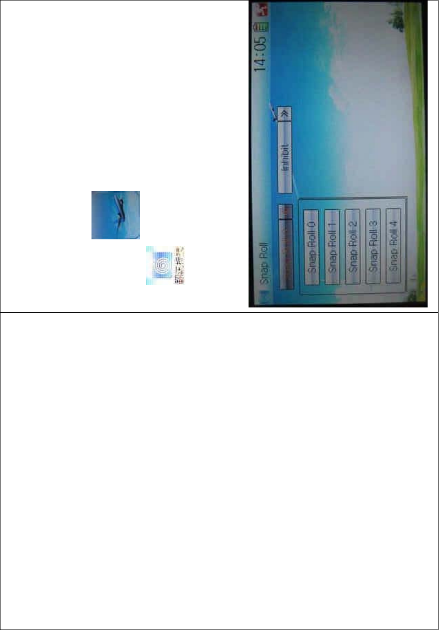
DEVO-8 Page no. Page 201 of 363
3.7 Snap roll
After the function of Snap Roll is set up, the switch or stick can be used
to control over the snap roll flight.
Setting method:
Touch the ico n to enter Function Menu, and then click the
icon to enter the interface of Snap Roll.
Setting for snap roll: touc h the navigation mark of Snap Roll and expand
a dropdown menu with five Snap Rolls. Click the snap roll you want to
use.
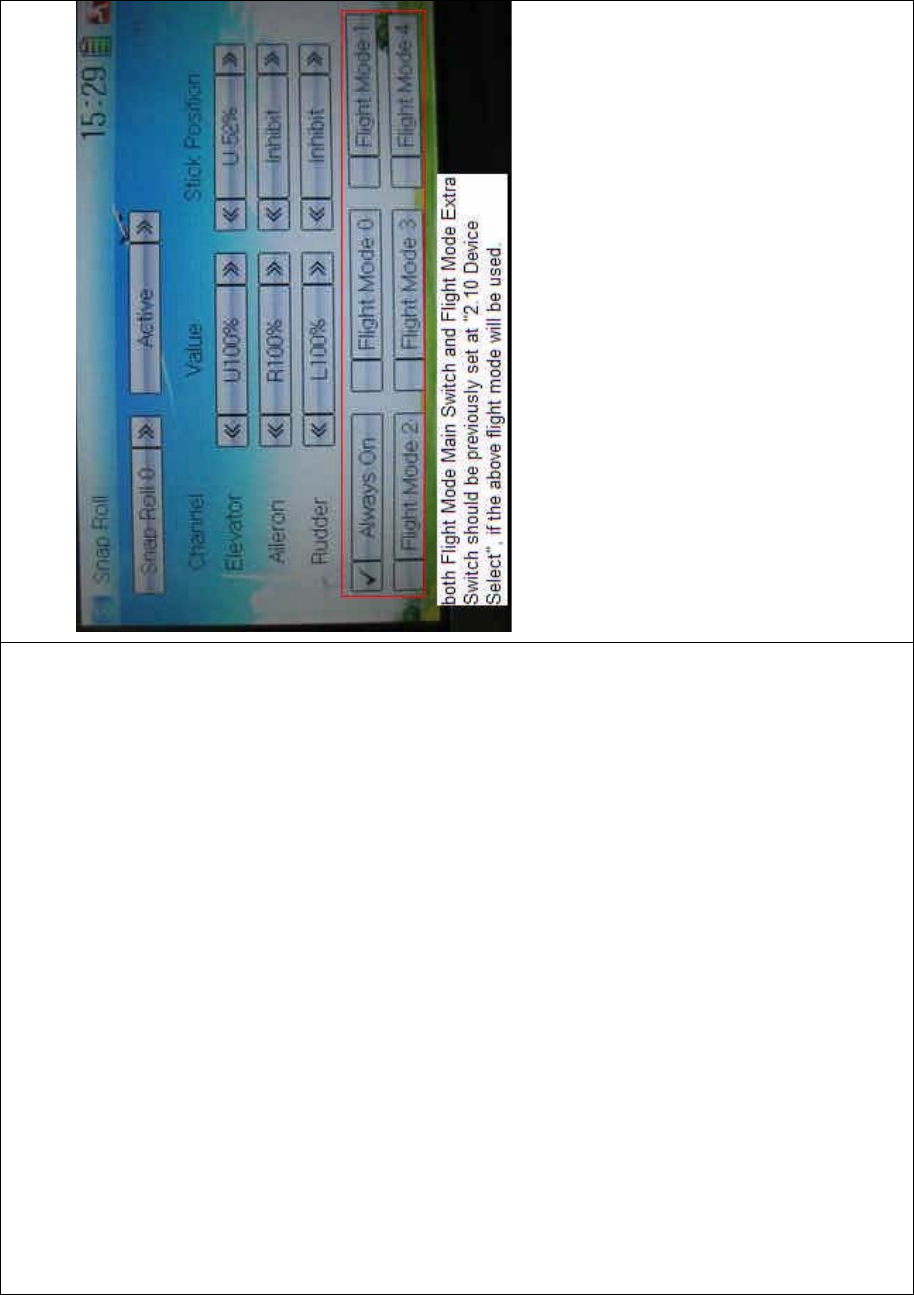
DEVO-8 Page no. Page 202 of 363
Touch the navigation mark of Inhibit and expand two options: Inhibit and
Active. A dropdown menu will be expanded after Active selected.
There show such items as Channel, Value, Stick Position and the flight
mode(ifbothFlightModeMainSwitchandFlightModeExtraSwitch
should be previously set at Device Select in Model Menu, if the flight
mode will be used. Refer to “2.10 Device Select”). Through changing
the amounts of Elevator, Aileron, and Rudder, respectively, set the snap
roll flight in the actions of left or right ascending, or left or right
descending. The snap roll flying can be controlled by the Training lever,
or by setting the corresponding stick position.
1) Value setting
Change the value, by touching the left or right navigation mark of
Elevator, Aileron, or Rudder, to set the corresponding servo lever’s
angle and the control direction. The adjustable range is 0-125%.

DEVO-8 Page no. Page 203 of 363
2) Stick position setting
Change the position, by touching the left or right navigation mark of
Elevator, Aileron, or Rudder, to set the stick position and the control
direction. If Stick Position is set as I nhibit, only Training lever can control
overthesnaprollflying.
3) Flight mode selection
It can be set in various flight modes whether or not to use the snap roll
function. All the flight modes are shown at the bottom or interface. Click
the flight mode you want.
Click the icon to exit after finished.
3.8 Differential
If want to use this function, Flaperon, DELTA, or 4-Aileron should be
previously selected in Wing Type of Model Menu. Refer to “2.12 Wing
Type”.
A. Aileron differential setting:
Touch the shortc ut icon to enter Function Menu, and then
click the icon to enter the interface of Differential.
Mounting servos in left and right ailerons are a must if usi ng this
function. The following interface will be shown after Flaperon, DELTA,
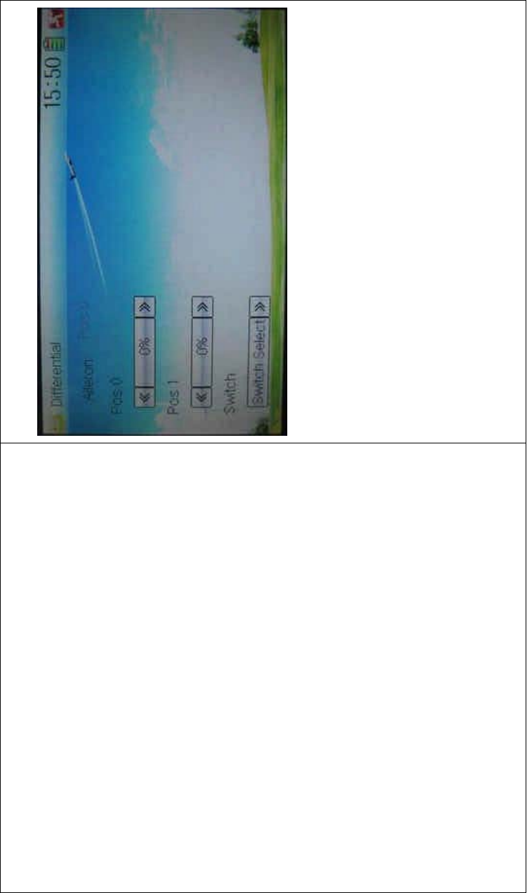
DEVO-8 Page no. Page 204 of 363
or 4-Aileron selected in Wing Type. Refer to “2.12 Wing Type”.
1) Setting for Pos 0
Touch the left or right navigation mark of Pos 0 to decrease or increase,
respectively, differential value. The bigger the value is, the bigger the
differential is. The adjustable range is ± 100%.
2) Setting for Pos 1
The setting is same as above.
3) Switch selection
It is possible to switch by setting switch when differential is in use.
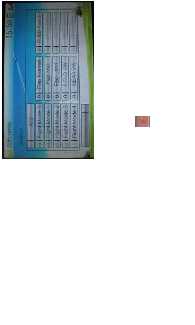
DEVO-8 Page no. Page 205 of 363
Touch the navigation mark of Switch and expand a selectable list. Click
the switch item, which you desire, to change “0” into “1”. If two or more
switch items are selected, the item And should be chosen. Then click
the navigation mark to return.
Click the icon to exit after finished.
B. Rudder differential setting
V-Tail should be previously set in Wing Type of Model Menu if the
rudder differential function is activated. Refer to “2.12 Wing Type”. And
then the following interface will be shown:
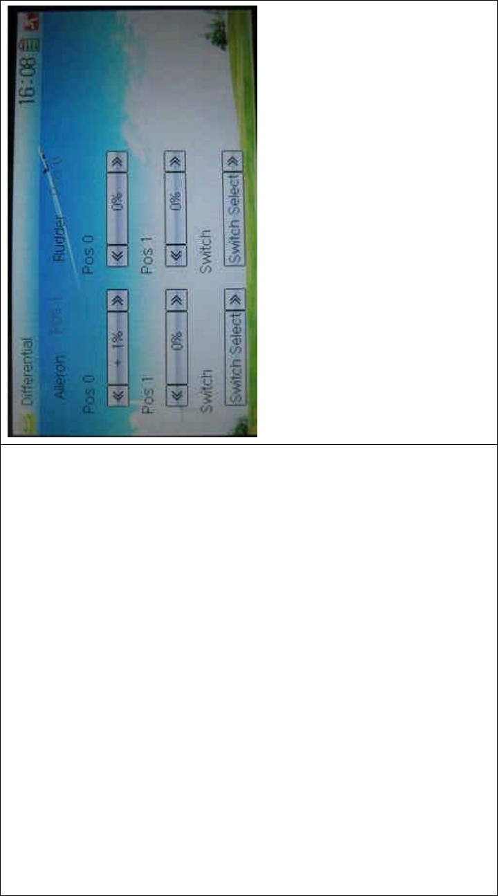
DEVO-8 Page no. Page 206 of 363
1) Setting for Pos 0
Touch the left or right navigation mark of Pos 0 to decrease or increase,
respectively, differential value. The bigger the value is, the bigger the
differential is. The adjustable range is ± 100%.
2) Setting for Pos 1
The setting is same as above.
3) Switch selection
It is possible to switch by setting switch when differential is in use.

DEVO-8 Page no. Page 207 of 363
Touch the navigation mark of Switch and expand a selectable list. Click
the switch item, which you desire, to change “0” into “1”. If two or more
switch items are selected, And should be chosen. Then click the
navigation mark to return.
Click the icon to exit after finished.
C. Flap differential setting
It should be previously set the flap dual channel function in Device
Output at Model Menu (refer to “2.12 Wing Type”) in order to activate
the menu of Flap Differential.

DEVO-8 Page no. Page 208 of 363
1˅Setting for Pos 0
Touch the left or right navigation mark of Pos 0 to decrease or increase,
respectively, differential value. The bigger the value is, the bigger the
differential is. The adjustable range is ± 100%.
2˅Setting for Pos 1
The setting is same as above.
3) Switch selection
It is possible to switch by setting switch when differential is in use.
3.9 Balance
This function can adjust the parameters of the two servos which are
used in the dual channels. It should be previously chosen one of the
these wing types of Flaperon, DELTA, 4 Aileron, and V Tail in Wing Type
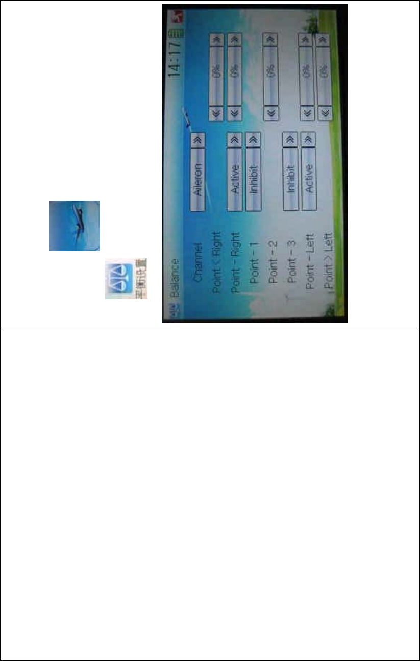
DEVO-8 Page no. Page 209 of 363
at Model Menu. Refer to “2.12 Wing Type”.
Setting method:
Touch the ico n to enter Function Menu, and then click the
icon to enter the BALANCE INTERFACE.
1) Channel selection
Touch the navigation mark of Channel and expand a selectable list.
Choose the desired channel.
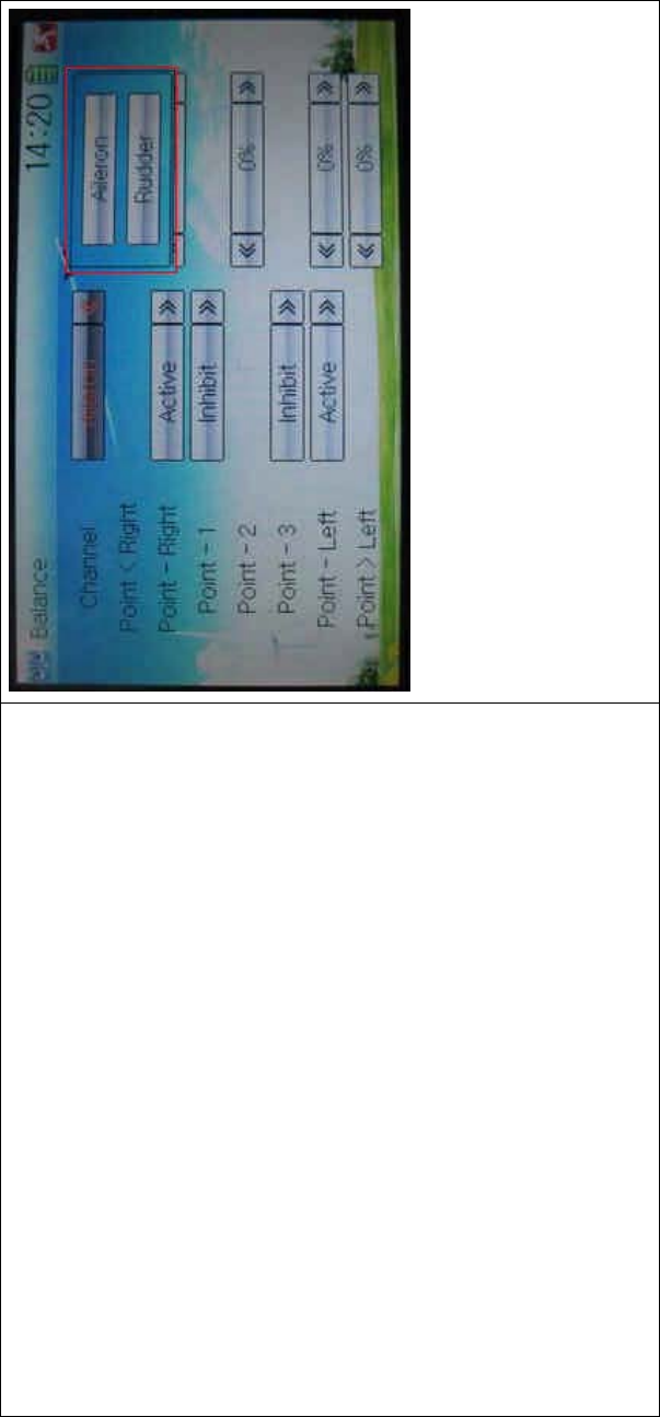
DEVO-8 Page no. Page 210 of 363
2) Point parameter adjustment
Touch the navigation mark of Point that you want to select, and pops up
a dropdown menu including Inhibit and Active. Click Active for adjusting
the value by touching the left or right navigation mark. 0% means no
adjusting. A minus value means the amending direction is downward,
and a plus value means the amending direction is upward.
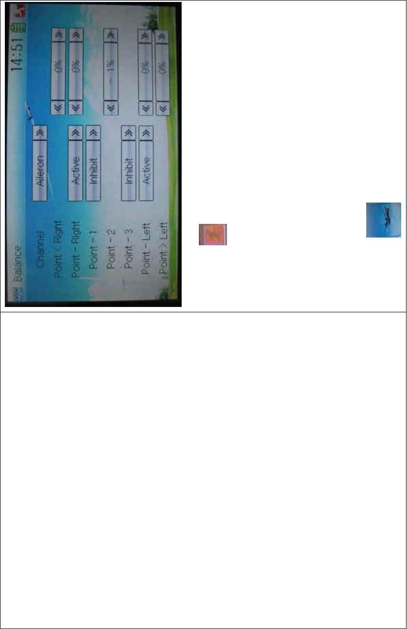
DEVO-8 Page no. Page 211 of 363
Click the icon to exit after finished.
3.10 Gyro sensor
This functio n offers the gai n adjustment for gyro sensor, which can be
manually set through D/R switches or Flight mode switch, and also is
possible to be automatically switched among various gains through
flight mode switch. (The flight mode should be activated. Refer to “2.10
Device Select”).
Setting method:
Touch the icon to enter Function Menu, and then touch the
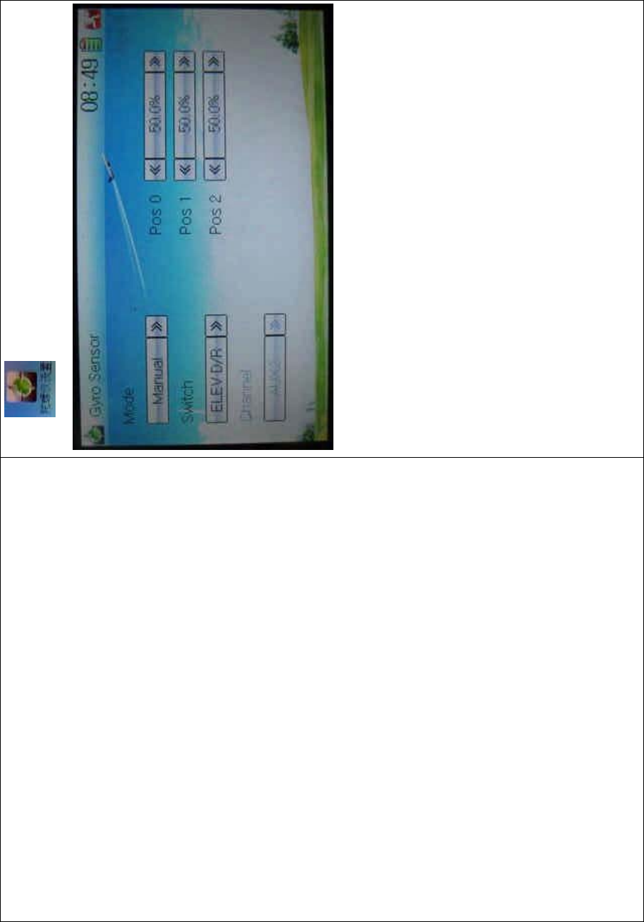
DEVO-8 Page no. Page 212 of 363
icon to enter GYRO SENSOR INTERFACE.
A. Manual setting
1) Mode selection
Touch the navigation mark of Mode and expand into two options:
Manual and Automatic. Select Manual.
2) Switch selection
Touch the navigation mark of Switch and expand into five articles:
FMOD SW, MIX SW, ELEV D/R, AILE D/R, and RUDD D/R.
3) Channel setting
The default setting is AUX 2. It is possible to alter into other channels by
choosing in the item of Device Output (refer to “2.11 Device Output”).
4) Gain adjustment
There are total three levels for respective setting: Pos 0, Pos 1, and Pos
2.
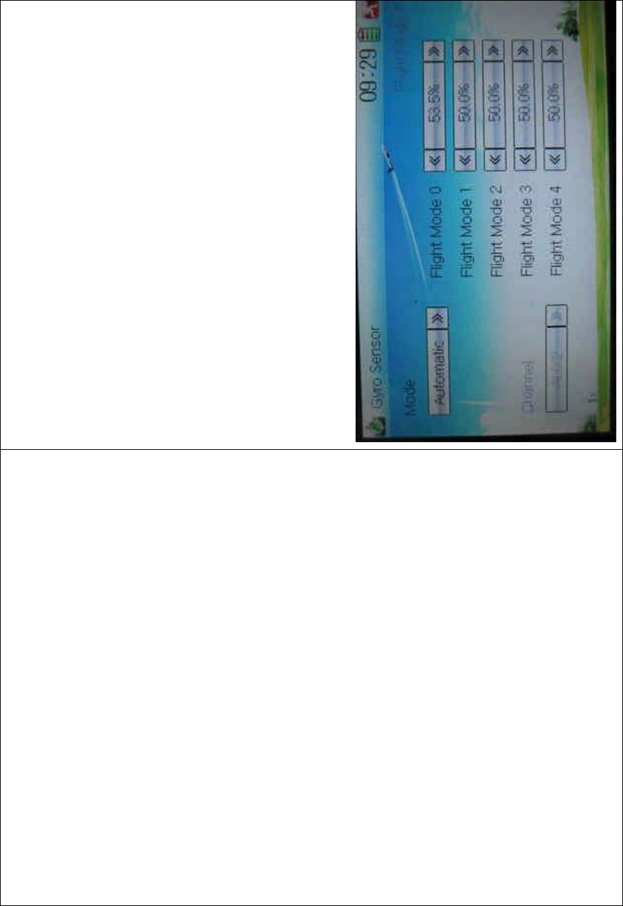
DEVO-8 Page no. Page 213 of 363
4.1) Pos 0
Touch the left or right navigation of the flight mode you want to adjust to
decrease or increase, respectively, the value with a range of 0.0% -
100.0%.
If the gyro used has two modes of NOR and AVCS, NOR will be
activated when the value is less than 50.0%, and AVCS activated when
above 50.0%. In NOR mode, the smaller the value is, the bigger the
sensitivity will be; in AVCS mode, the bigger the value is, the bigger the
gyro sensor gain will be. The factory setting is 50.0%.
4.2) Pos 1
Refertothestepof“4.1)Pos0”.
4.3) Pos 2
Refertothestepof“4.1)Pos0”.
B. Automatic setting

DEVO-8 Page no. Page 214 of 363
1) Mode selection
Touch the navigation of Mode and expand into two options: Manual and
Automatic. Select Automatic.
2) Channel output
The default setting is AUX 2. It is possible to alter into other channels in
the interface of Device Output (Refer to “2.11 Device Output”).
3˅Flight mode selection
All the flight modes are shown in the right interface which includes
Flight Mode 0, Flight Mode 1, Flight Mode 2, Flight Mode 3, and Flight
Mode 4. .
For Flight Mode 3 and Flight Mode 4, Flight Mode Extra Switc h should
be activated in Device Select (Refer to “2.10 Device Select”).
Click the left or right navigation mark of the flight mode, which you want
to automatically adjust, to decrease or increase the amount of gyro
gains, respectively. If the gyro you use has two modes of NOR or AVCS,
when the amount is less than 50.0%, NOR mode will be activated. The
lesser the amount is, the bigger the gyro gain becomes. The default
setting is 50.0%.
Click the icon to exit.
3.11 Governor
Governor should be set at Device Output (Refer to “2.11 Device
Output”).
The control proportion of governor can be separately set in various flight
modes. For the absolute revolution amount, please set in external
governor. The amount shown in DEVO-8’s governor is just a
percentage for reference. The actual revolution should be read in the
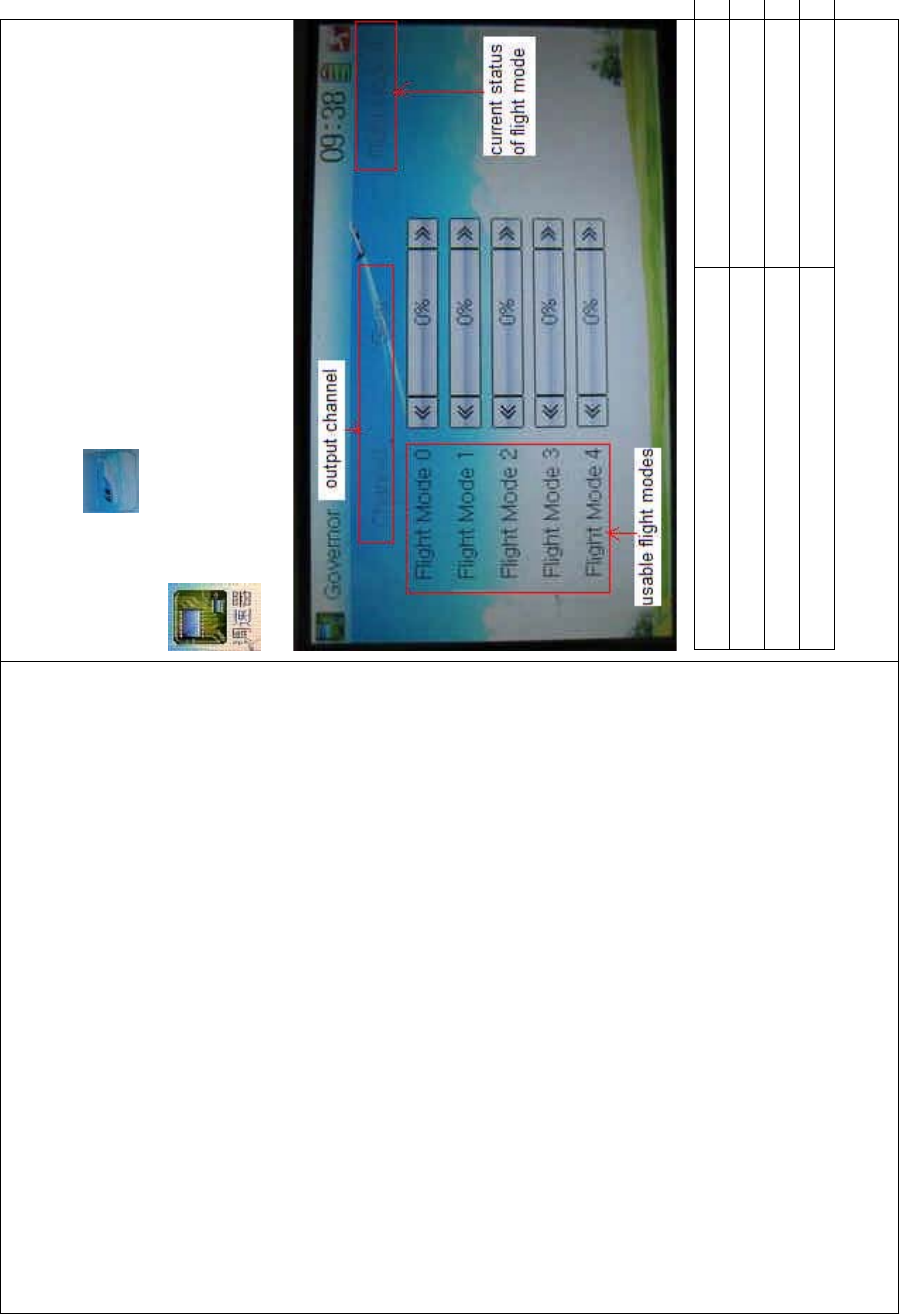
DEVO-8 Page no. Page 215 of 363
external governor.
Setting method:
Touch the icon to enter Function Menu, and then click the icon
to enter the GOVERNOR INTERFACE.
English Your language
Output channel
Usable flight modes
Currentstatusofflightmode
The output channel, current statuses of flight modes and usable flight

DEVO-8 Page no. Page 216 of 363
modes are shown in the interface. According to the requirement, touch
the correspo nding f light mode to set the amo unt. Click the left or right
navigation mark to separately decrease or increase the amount. The
adjustable range is ± 125%.
Click the icon to exit after finished.
3.12 Aileron to Rudder Mix
This function is possible to execute the mix of aileron to rudder, which is
controlled by switch.
Setting method:
Touch the ico n to enter Function Menu, and then click the
icon to enter the ALERON TO RUDDER MIX
INTERFACE.
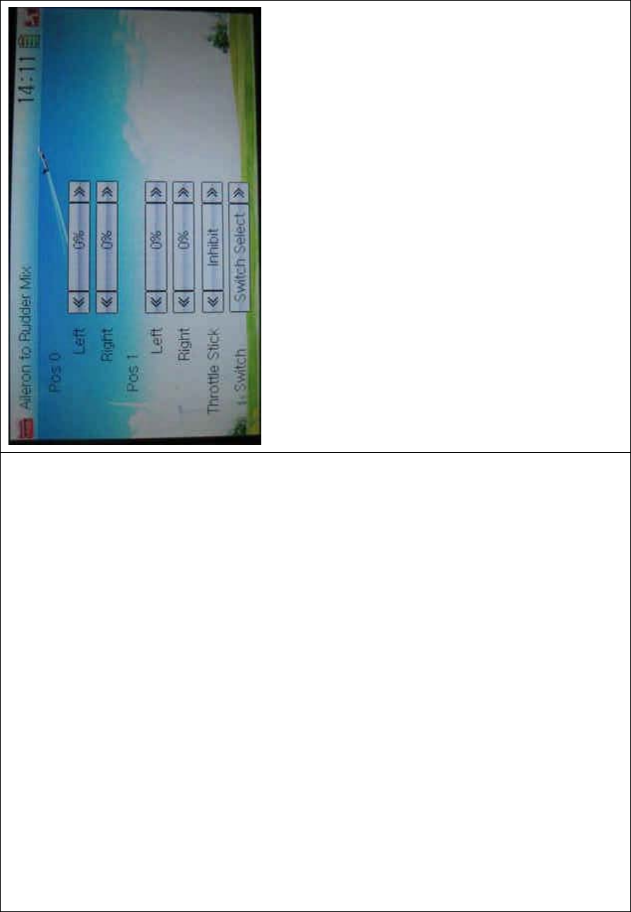
DEVO-8 Page no. Page 217 of 363
1) Pos 0 Setting
Touch the left or right navigation mark of Left to change the value, and
leftward mix value of aileron to rudder will be changed. The mix
direction will be revised by changing the sign of plus or minus before
the value. The adjustable range is ±125%.
Touch the left or right navigation mark of Right to change the value, and
the rightward mix value of aileron to rudder will be changed. The mix
direction will be revised by changing the sign of plus or minus before
the value. The adjustable range is ±125%.
2) Pos 1 setting
The setting is same as above.
3) Throttle stick setting
The switch between Pos 0 and Pos 1 can be realized by setting the
position of throttle stick. Touch the left or right navigation mark of
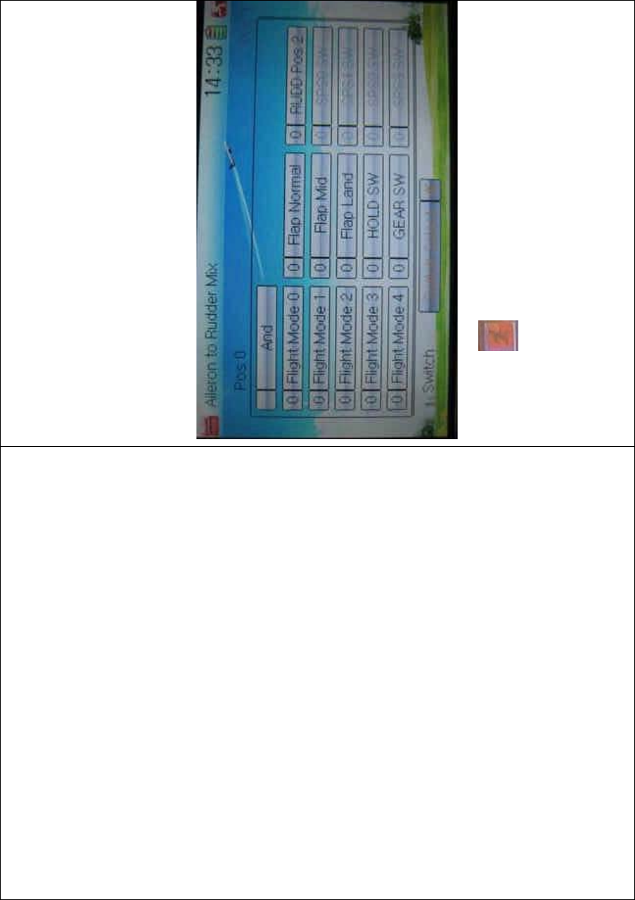
DEVO-8 Page no. Page 218 of 363
Throttle Stick to set the position amount of throttle stick. The default
setting is Inhibit. The adjustable range is 0.0-100.0%.
4) Switch setting
Touch the navigation mark of Switch and expand a dropdown menu
including some selectable items. Click the desired item and “0” before
the item will be changed into “1”. If two or more items are selected, the
item And should be selected. Then touch the navigation mark to return
back.
Click the icon to exit after finished.
3.13 Elevator to flap mix
This function is used to execute the mix of elevator to flap.
Setting method:
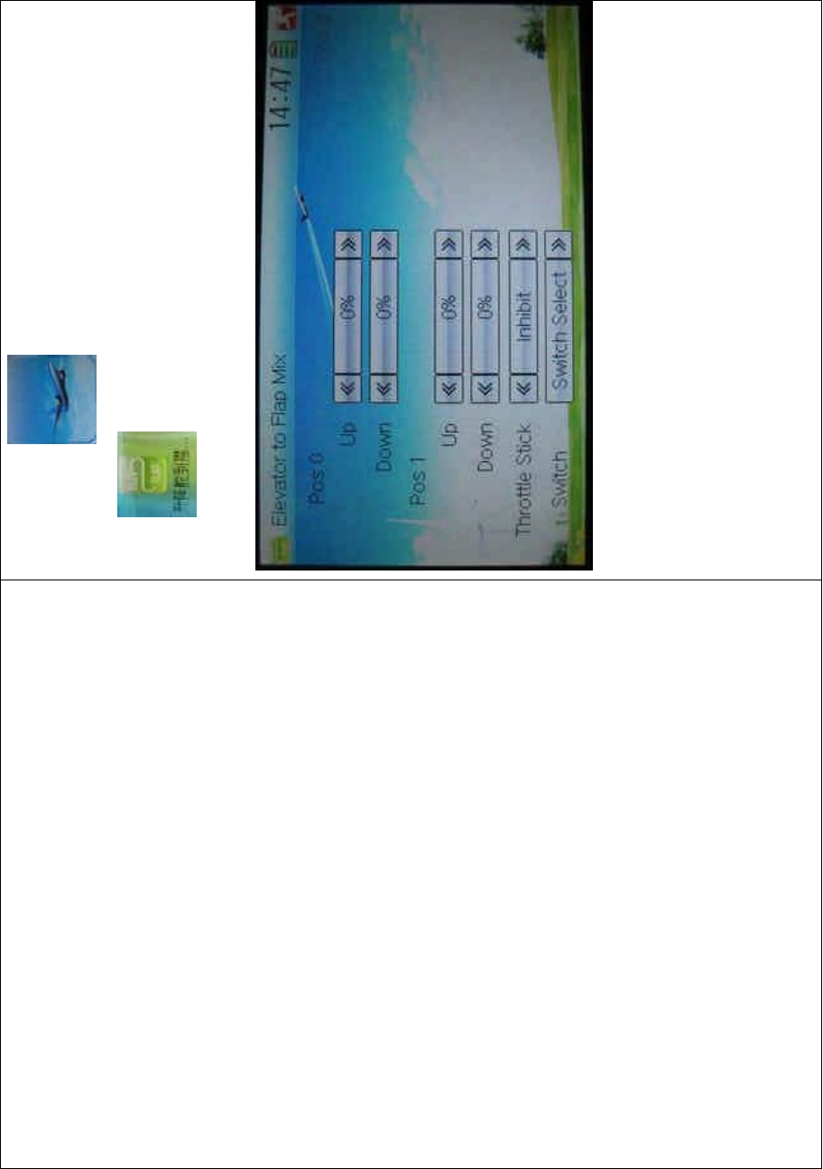
DEVO-8 Page no. Page 219 of 363
Touch the ico n to enter Function Menu, and then click the
icon to enter the ELEVATOR FLAP MIX
INTERFACE.
1) Pos 0 setting
Touch the left or right navigation mark of Up to change the value, and
upward mix value of elevator to flap will be changed. The mix direction
will be revised by changing the sign of plus or minus before the value.
The adjustable range is ±125%.
Touch the left or right navigation mark of Down to change the value, and
thedownwardmixvalueofelevatortoflapwillbechanged.Themix

DEVO-8 Page no. Page 220 of 363
direction will be revised by changing the sign of plus or minus before
the value. The adjustable range is ±125%.
2) Pos 1 setting
The setting is same as above.
3) Throttle stick setting
The switch between Pos 0 and Pos 1 can be realized by setting the
position of throttle stick. Touch the left or right navigation mark of
Throttle Stick to set the position amount of throttle stick. The default
setting is Inhibit. The adjustable range is 0.0-100.0%.
4) Switch setting
Touch the navigation mark of Switch and expand a dropdown menu
including some selectable items. Click the desired item and “0” before
the item will be changed into “1”. If two or more items are selected, the
item And should be selected. Then touch the navigation mark to return
back.
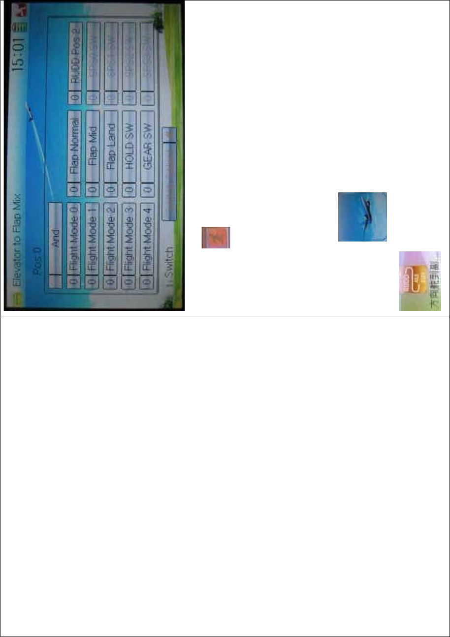
DEVO-8 Page no. Page 221 of 363
Click the icon to exit.
3.14 Rudder to aileron/elevator mix
This function is used to execute the mix of rudder to aileron/ elevator. It
will help eliminate waver or shake caused by rudder stick operation.
Setting method:
To uc h t h e ic o n to enter Function Menu, and then click
to enter the ELEVATOR TO AILERON/ELEVATOR
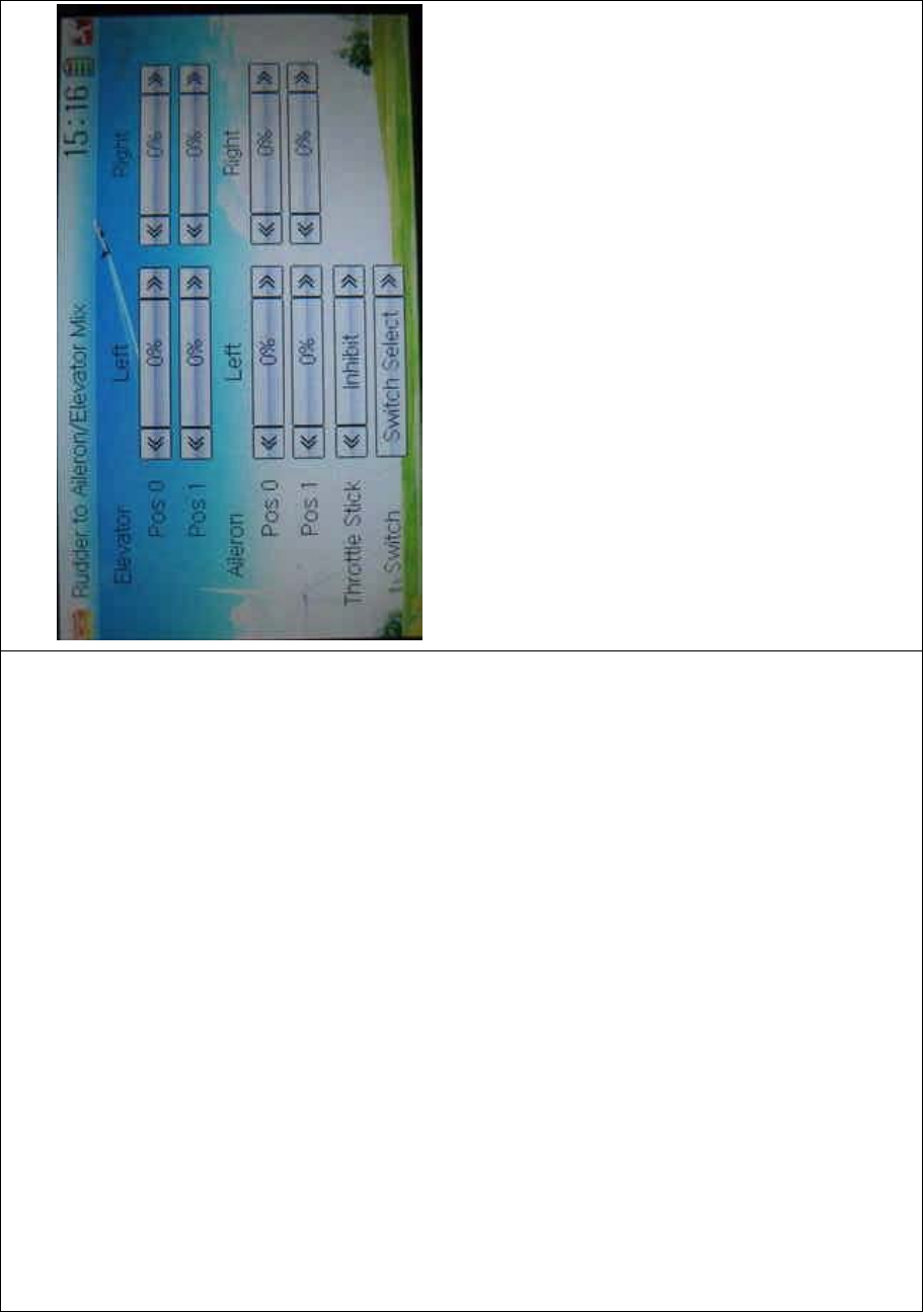
DEVO-8 Page no. Page 222 of 363
MIX INTERFACE.
1) Elevator setting
1.1) Pos 0 setting:
Touch the left or right navigation mark of Left at Pos 0 to change the
value, and the leftward mix value of rudder to elevator will be changed.
Touch the left or right navigation mark of Right at Pos 0 to change the
value, and the l rightward mix value of rudder to elevator will be
changed.
The mix direction will be revised by changing the sign of plus or minus
before the value. The adjustable range is ±125%.
1.2) Pos 1 setting
Setting is same as above.
2) Aileron setting
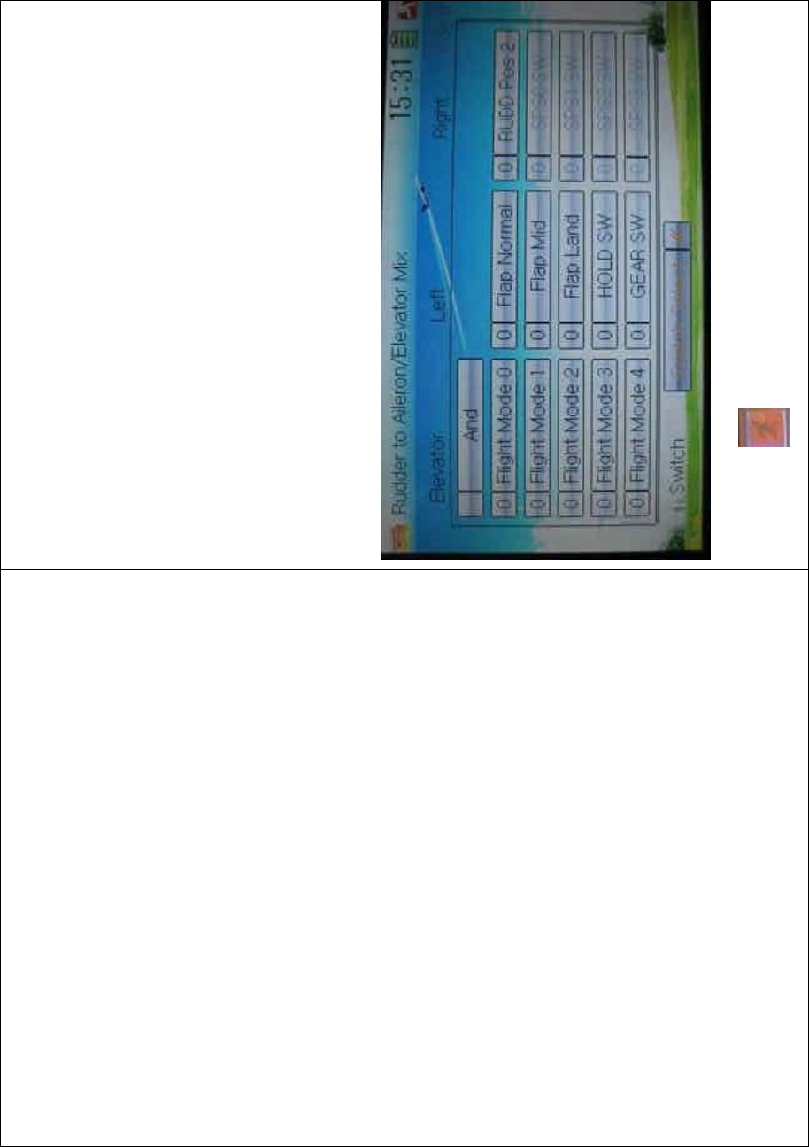
DEVO-8 Page no. Page 223 of 363
Setting is same as above.
3) Throttle stick setting
The switch between Pos 0 and Pos 1 can be realized by setting the
position of throttle stick. Touch the left or right navigation mark of
Throttle Stick to set its position amount. The default setting is Inhibit.
The adjustable range is 0.0-100.0%.
4) Switch setting
Touch the navigation mark of Switch and expand a dropdown menu
including some selectable items. Click the desired item and “0” before
the item will be changed into “1”. If two or more items are selected, the
item And should be selected. Then touch the navigation mark to return
back.
Click the icon to exit after finished.
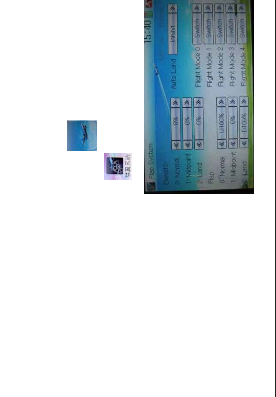
DEVO-8 Page no. Page 224 of 363
3.15 Flap system
This function can modify some effects on elevator. It is possible to set
three statuses of elevator and three statuses of flap, respectively,
through three-way flap control switch.
Setting method:
Touch the ico n to enter Function Menu, and then click the
icon to enter Flap System.
1) Elevator setting
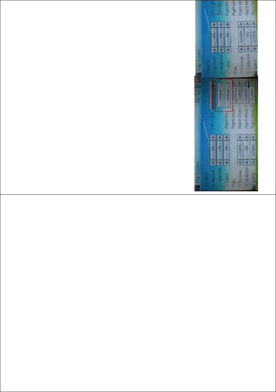
DEVO-8 Page no. Page 225 of 363
There three options: 0: Normal, 1: Midpoint, and 2: Land.
1.1) 0: Normal position
Touch the navigation mark of Normal to change the mix amount. It is
possible to change the direction by altering D or U before the amount.
The default setting is 0%, and the adjustable range is U125% to
D125%.
1.2) 1: Midpoint
The setting is same as above.
1.3) 2: Land
The setting is same as above.
2) Flap setting
ThesettingforFlapissameasElevator.
3) Auto land
Touch the navigation mark of Auto Land, and expand a dropdown menu
including Inhibit and Active. If select Active, another sub menu Throttle
will be shown under Auto Land.
3.1) Throttle stick position setting
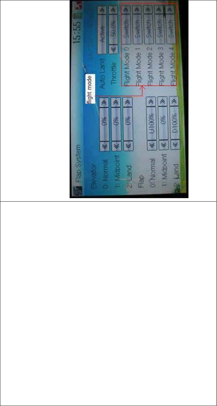
DEVO-8 Page no. Page 226 of 363
Touch the navigation mark of Throttle to set the throttle stick position.
The adjustable range is 0.0-100.0%.
3.2) Flight mode setting
Auto landing switch can be set in a certain flight mode. This setting
should be previously set in Wing Type at Model Menu. Refer to “2.13
Wing Type”.
Touch the navigation mark of the selected flight mode, and pops up a
menu with Switch, Normal, Midpoint, and Land.
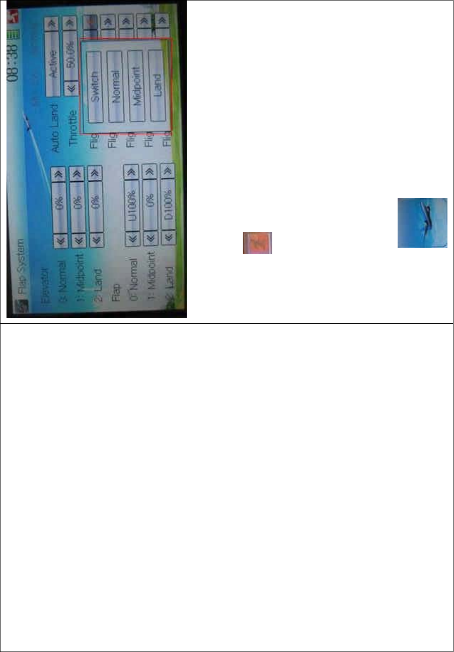
DEVO-8 Page no. Page 227 of 363
The selected item will be shown in the corresponding flight mode.
Select Switch for manual control of landing.
Click the icon to exit.
3.16 Aileron to flap mix
Thisfunctioncanexecutethemixofailerontoflap,andcanalsoset
switch. The flap dual channels should be previously set in Wing Type at
Model Menu (Refer to “2.12 Wing Type”).
Setting method:
Touch the ico n to enter Function Menu, and then click the
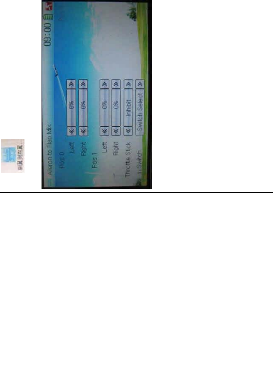
DEVO-8 Page no. Page 228 of 363
icon to enter the AILERON TO FLAP MIX
INTERFACE.
1) Pos 0 setting
Touch the left or right navigation mark of Left at Pos 0 to change the
leftward mix value of aileron to flap.
Touch the left or right navigation mark of Right at Pos 0 to change the
rightward mix value of aileron to flap.
The mix direction will be revised by changing the sign of plus or minus
before the value. The adjustable range is ±125%.
2) Pos 1 setting
The setting is same as the above.
3) Throttle Stick setting
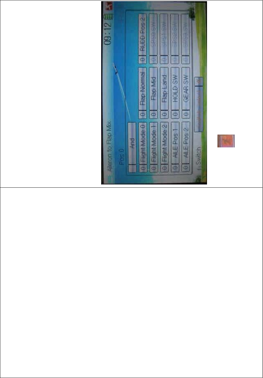
DEVO-8 Page no. Page 229 of 363
The switch between Pos 0 and Pos 1 can be realized by setting the
position of throttle stick. Touch the left or right navigation mark of
Throttle Stick to set the position amount of throttle stick. The default
setting is Inhibit. The adjustable range is 0.0-100.0%.
4) Switch setting
Touch the navigation mark of Switch and expand a dropdown menu
including some selectable items. Click the desired item and “0” before
the item will be changed into “1”. If two or more items are selected, the
item And should be selected. Then touch the navigation mark to return
back.
Click the icon to exit.
3.17 Pitch curve
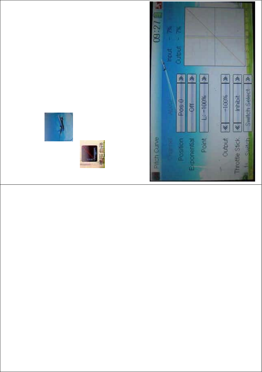
DEVO-8 Page no. Page 230 of 363
Pitch Curve can be adjusted via nine points. Pitch curves of Pos 0 and
Pos 1 can be set, respectively. The item Pitch should be previously set
in Device Output at Model Menu (Refer to “2.12 Device Output”).
Setting method:
To uc h t he i co n to enter Function Menu and then click the
icon to enter the interface of Pitch Curve. A dropdown
menu with “All Servos Hold” will pop up. Click OK for locking all the
current statuses of servos, and click Cancel for unlocking the current
statuses. And the interface will show the current used channel and the
current position statuses of switches.
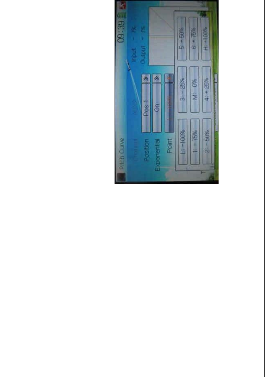
DEVO-8 Page no. Page 231 of 363
1) Position setting
Touch the navigation mark of Position and expand a sub menu with Pos
0 and Pos 1. Choose the desired position.
2) Exponential s etti ng
Touch the navigation mark of Exponential, and expand a sub menu with
Off and On. C lick O n for smooth changes, and Off for changes in the
form of fold line in pitch curve, respectively.
3) Point setting
Touch the navigation mark of Point and expand a dropdown menu
inc luding ni ne points. C hoose the point you want to adjust.
4) Status setting
Touch the navigation mark of Status and expand a list with Inhibit and
Active. Click Inhibit for keeping the value of the selected point. The
default setting is Inhibit. The item of Output will pop up after clicking
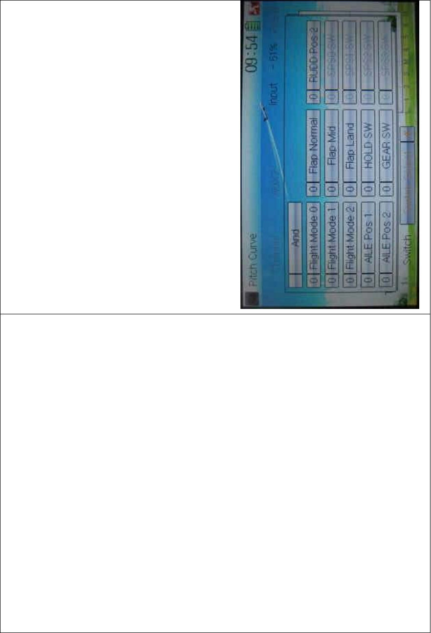
DEVO-8 Page no. Page 232 of 363
Active
5) Output setting
Touch the left or right navigation mark of Output to decrease or
increase, respectively, the output value. The adjustable range is ±
100%.
6) Throttle stick setting
The throttle stick can be set as a switch by touching the navigation mark
of Throttle Stick. The adjustable range is 0.0 – 100.0%. Choose Inhibit
and the throttle stick will not be set as a switch.
7) Switch setting
Touch the navigation mark of Switch and expand a selectable list. Click
the switch item that you want to set. If two or more switches are
selected, the item A nd sho uld be chosen.

DEVO-8 Page no. Page 233 of 363
Then click the icon to exit.
3.18 Program mix
There are total eight sets of Program Mix. It is possible to freely set the
channels and amounts which you want to select and amend,
respectively.
Setting method:
To uc h t h e i co n to enter Function Menu, and then click
to enter the PROGRAM MIX INTERFACE.Eight
Program Mix names and their current statuses are shown (the factory
default setting is Inhibit). Take Program Mix 1 as an example to show
how to use.
.

DEVO-8 Page no. Page 234 of 363
A. Setting method for Normal in Program Mix 1
Touch the item Normal in Program Mix 1 and expands an enquiry “All
Servos Hold?” Click OK for all the servos will be locked at the current
statuses; click Cancel for unlocked. Enter the next interface after
clicking.

DEVO-8 Page no. Page 235 of 363
1) Mater channel setting
Touch the navigation mark of Master and expands a selectable
dropdown menu. After clicking the desired channel the channel name
willbeshowninMaster.
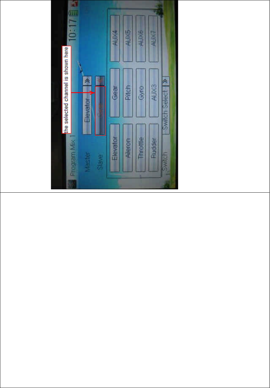
DEVO-8 Page no. Page 236 of 363
2) Slave channel setting
Touch the navigation mark of Slave and expands a selectable
dropdown menu. Click the desired channel which will be shown in
Slave.
3) Gain setting
Take Elevator at Master as an example.
3.1) Mix amount setting at Pos 0 when elevator stick moved upward
Touch left or right navigation mark of Up to decrease or increase,
separately, the mix amount. It is possible to reverse mix direction
through changing the plus or minus sign before amount. The adjustable
range is ±125%.
3.2) Mix amount setting at Pos 0 when elevator stick moved downward

DEVO-8 Page no. Page 237 of 363
Touch left or right navigation mark of Down to decrease or increase,
separately, the mix amount. It is possible to reverse mix direction
through changing the plus or minus sign before amount. The adjustable
range is ±125%.
3.3) The settings at Pos 1 and Offset are same as above.
4) Throttle stick setting
Touch the navigation mark of Throttle Stick to set its position as a free
switch. The adjustable range is 0.0-100.0%.
5) Switch selection
Touch the right navigation mark of Switch and pop up a dropdown menu
which contains the adjustable items. Click the desired switch. Then
touch the right navigation mark to return the previous interface.
Click the icon to return to the interface of Program Mix for other
setting, or click the icon once again to exit.
B. Setting method for Curve in Program Mix2
Touch the item Curve in Program Mix 1 and expands an enquiry “All
Servos Hold?” Click OK for all the servos will be locked at the current
statuses; click Cancel for unlocked. Enter the next interface after
clicking.

DEVO-8 Page no. Page 238 of 363
English Your language
Master control
Slave control
1) Master channel setting
Touch the navigation mark at master control and expand a selectable
dropdown menu. Select the desired channel and its name will be shown
in Master.
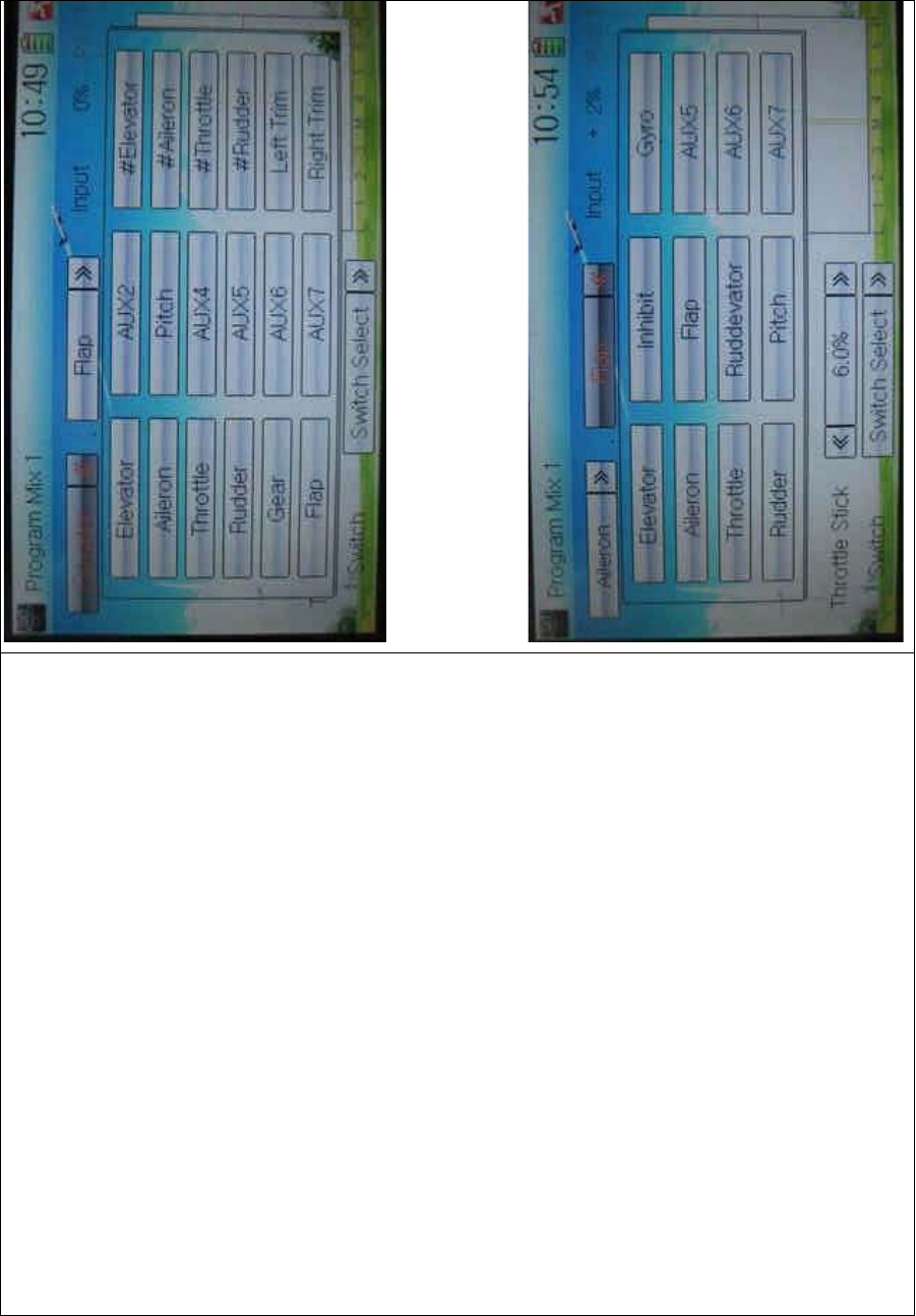
DEVO-8 Page no. Page 239 of 363
2) Slave channel setting
Touch the navigation mark at Slave control and expand a selectable
dropdown menu. Select the desired channel and its name will be shown
in Slave.

DEVO-8 Page no. Page 240 of 363
3) Position selection
There are two options: Pos 0 and Pos 1. Select the desired position by
touching the navigation mark.
4) Exponential
Touch the navigation mark of Exponential and expand a dropdown
menu with two options of Off and On. The pitch curve will be smoothly
changed if choosing On. Otherwise choosing Off.
5) Point setting
Touch the navigation mark of Point and expand a dropdown menu with
nine points. Click the point you want to set, and then touc h the
navigation mark to return.
6) Status setting
Touch the navigation mark of Status and expand a dropdown with two
options of Inhibit and Active. Touch Inhibit for unchangi ng t he current
amount (the default setti ng is Inhi bit); click Active for changi ng the
amount.
7) Output
Touch the left or right navigation mark of Output to decrease or
increase, respectively, the output amount. It is possible to reverse the
mix direction by changing the plus or minus sign before the amount.
The adjustable range is ±125%.
8) Throttle
Touch the navigation mark of Throttle to set the position, which the
throttle stick is set as switch to freely automatically switch.
9) Switch
Touch the navigation mark of Switch and expand a usable dropdown
menu. Select the desired switch, and then click the navigation mark to
return.

DEVO-8 Page no. Page 241 of 363
Click the icon to return to the interface of Program Mix for other
setting, or click the icon once again to exit.
3.19 Monitor
This function can display the current statuses and positions of all the
channels’ outputs, and check the current working status of each
channel.
Touch the icon to enter Function Menu, and then click the
icon to enter the MONITOR INTERFACE for checking the
current working status of each channel.
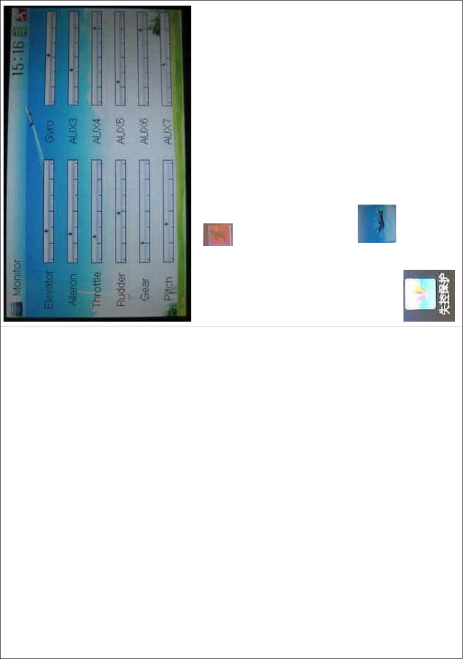
DEVO-8 Page no. Page 242 of 363
Click to the icon exit after finished.
3.20 Fail safe
There are two possibilities for use if the transmission signal is under
abnormal condition. The first one is to lock the last action data received;
the second one is to execute the pre-set data which is pre-set. The
default setting is Servo Hold.
Setting method:
Touch the icon
to enter Function Menu, and then click
to enter the interface of Fail Safe.

DEVO-8 Page no. Page 243 of 363
Take the item Elevator as an example to explain.
Elevator setting:
Touch the item Elevator and expand a sub-item in its right. Click the left
or right navigation mark to decrease or increase, respectively, the
position amount which centers on the neutral point of servo.
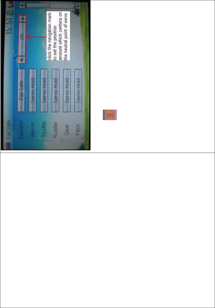
DEVO-8 Page no. Page 244 of 363
The setting methods for other channels are same as above.
Click the icon to exit after finished.
Note: checking whether all the actions when fail safe happened are
correct is a must after the setting is finished. It is dangerous to use full
throttle, especially after fail safe taken place.
3.21 Trainer
ThetrainingfunctioncanbepracticedviatwoDEVO-8equipments.
Setting method:
A. Data copy
Using the wireless copy function of the two DEVO-8 transmitters, the
model data saved in the trainer’s transmitter can be transmitted to the
trainee’s to ensure the model parameters are exactly same. Regarding
the copying method, refer to “2.4 Model Wireless Copy”
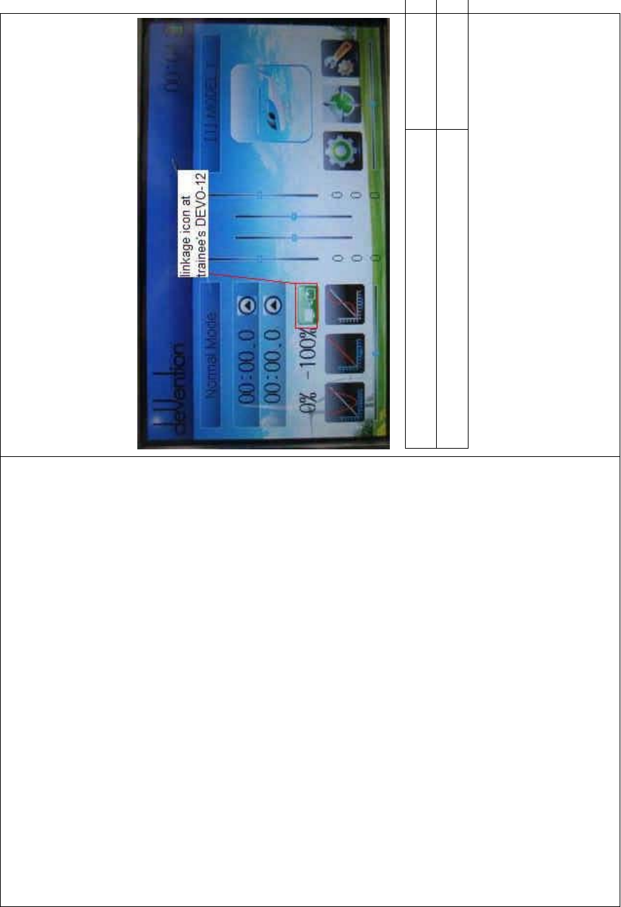
DEVO-8 Page no. Page 245 of 363
B. Linkage
Insert one end of the signal wire into DSC socket at the rear face of the
trainee’s DEVO-8, and then turn on the power. A linkage icon will be
shown on the boot screen. Find out the trainee’s model data.
English Your language
Linkage icon at trainee’s icon
Turnonthepowerofthetrainer’sDEVO-8.Findoutthetrainee’smodel
data, and let the trainer’s DEVO-8 fly the aircraft model normally. Then
turn off the power.
Insert the other end of the digital signal wire into the trainer’s DEVO-8,
and then turn on its power. A linkage icon will be shown as below:

DEVO-8 Page no. Page 246 of 363
English Your language
Linkage icon at trainer’s DEVO-8
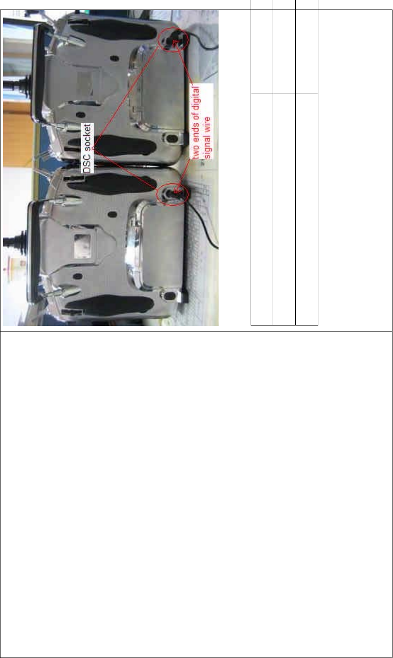
DEVO-8 Page no. Page 247 of 363
English Your language
DSC socket
Two ends of digital signal wire
Training status display: when the trainer’s icon becomes into “X”, the
trai nee stops flying and t he trainer is worki ng; when the trai ner’s icon
turns into ĀĜ”, the trainee is flying and the trainer is in leisure.

DEVO-8 Page no. Page 248 of 363
English Your language
Trainee is off and trainer is working
Trainee is worki ng and trainer is off
C) Usage method
The traini ng switch should be worked with the TRN traini ng lever at the
right top of DEVO-8.
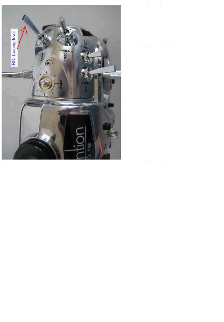
DEVO-8 Page no. Page 249 of 363
English Your language
TRN: traini ng lever
,IWKHWUDLQHU¶VILQJHUSXOOVWKHWUDLQLQJOHYHU751D³¥´LVVKRZQLQWKH
linkage icon; if the trainer releases his finger from the trainer lever, an
“X” will be shown there.
Setting for traini ng f unction c hannels
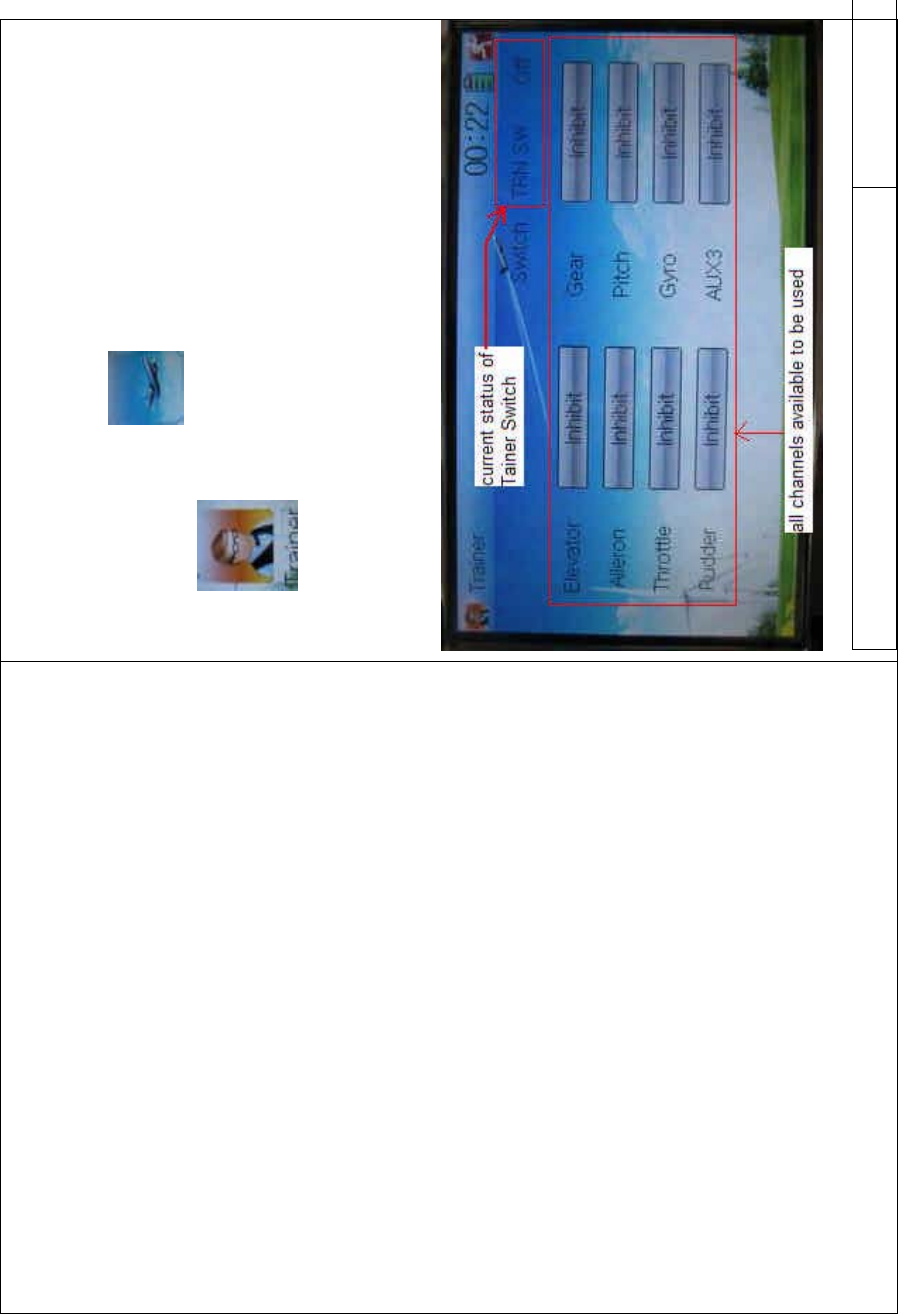
DEVO-8 Page no. Page 250 of 363
Trainee is available to get full or part of flight control power to the
aircraft model via setting the training function channel in the trainer’s
DEVO-8. Below is the setting method:
Touch the shortcut icon to enter Function Menu, and then
touch in Function Menu access to Trainer screen. The
available channels are shown below, and the current status of trainer
switch TRN is also shown.
English Your language
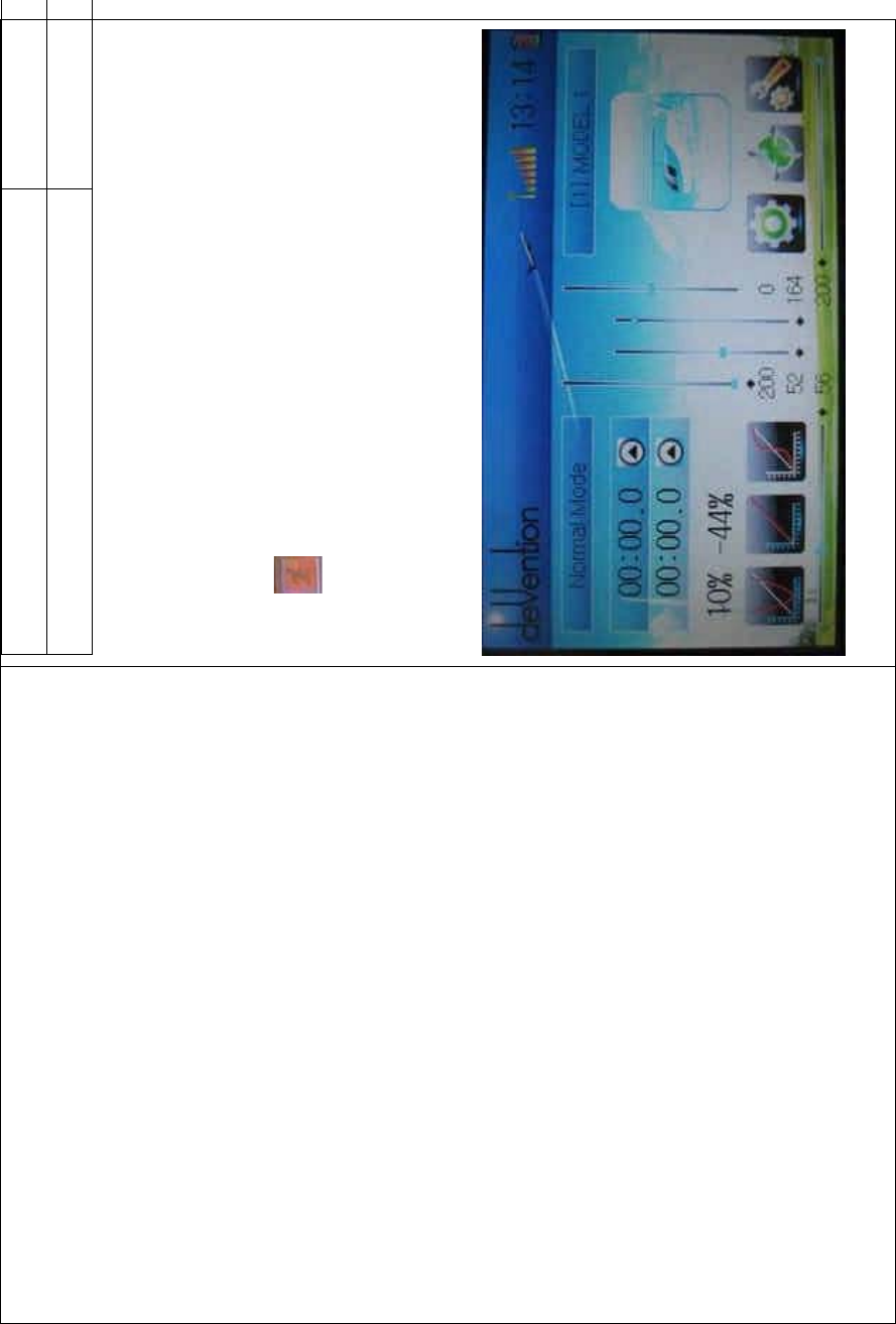
DEVO-8 Page no. Page 251 of 363
Current status of Trainer Switch (TRN SW)
All channels available to be used
Touch the channel(s) which you desire to grant to trainee. The
channel(s) you have touched will be activated as “Active”. The channels
which are not granted to trainee keep inhibited. The default setting is
“Inhibit”.
To uc h to save and exit after finished.
3.22 Timer
There are two timers which can be set as stopwatch and countdown,
respectively. Each timer can be operated by switch or by shortcut.
Setting method:
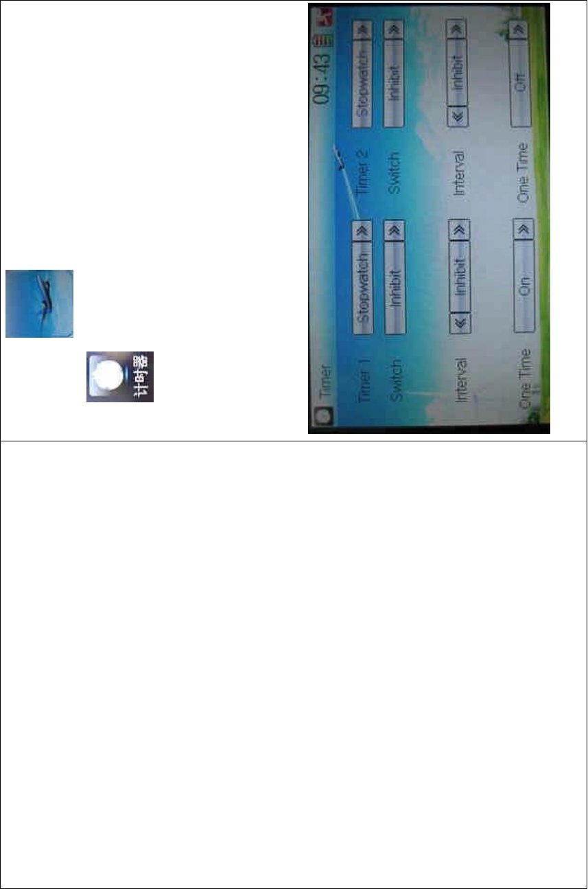
DEVO-8 Page no. Page 252 of 363
Touch the ico n to enter Function Menu, and then click the
icon to enter the interface of Timer.
A. Setting for Timer 1
1) Timer 1 setting
Touch the navigation mark of Timer 1 and expand a dropdown of
Stopwatch and Countdown. Select the desired timing method. The
timing range of stopwatch is from 0 to 59:59 (59 minutes 59 seconds).
Stopwatch view:
Countdown view:

DEVO-8 Page no. Page 253 of 363
Take countdown manner as an example to explain.
2) Switch selection
Touch the navigation mark of Switch and get a selectable dropdown

DEVO-8 Page no. Page 254 of 363
We can select the desired item but these items of SPS0 SW, SPS1 SW,
SPS2, and SPS3 which should be previously set at Stick Position
Switch at Model Menu (refer to “2.8 Stick Position Switch”).
3) Set time
The settable countdown time range is from 00:05 to 59:55.
4) Interval
This item offers the possibility to set the warning interval. It will warn
once every interval time. The adjustable range is from 00.05 to 05:00.
The default setting is Inhibit.
5) Down alarm
It is possible to set the down alarm in countdown. The setting range is
from 00:01 to 03:00. The default setting is Inhibit.
6) One time
If this function is turned on, counting down cannot be stopped once the
countdown works. The default setting is Off.
B. Setting for Timer 2 is same as that for timer 1.
Touch the icon to exit after finished.
Part four: Glider
1.0 System menu
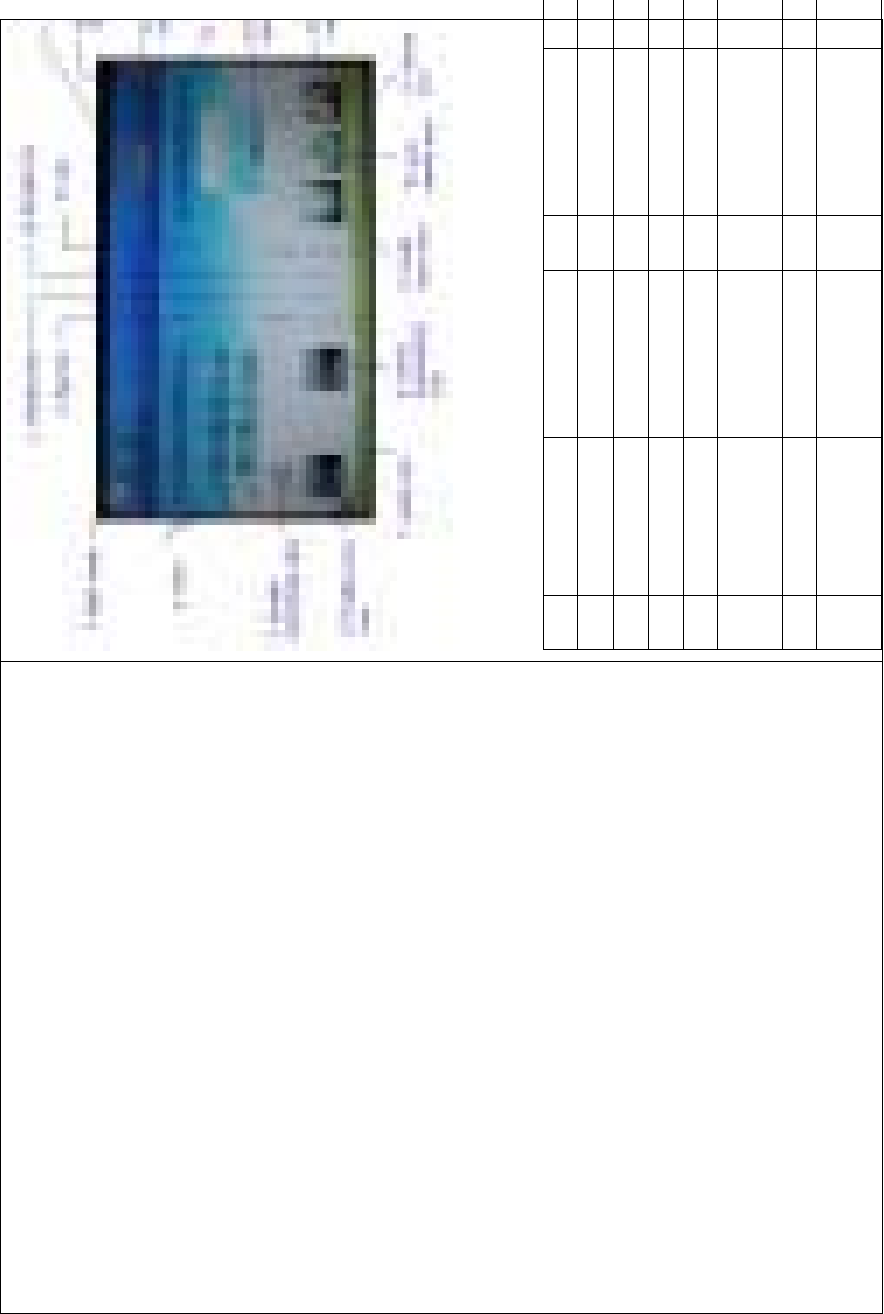
DEVO-8 Page no. Page 255 of 363
N/O English name Your language N/O English name You
r
1 Elevator trim 10
2Flaptrim 11
3 Flight mode 12
4 Timer 13
5 Flaperon mix
icon
14
6 Rudder trim 15
7 Brake system
icon
16
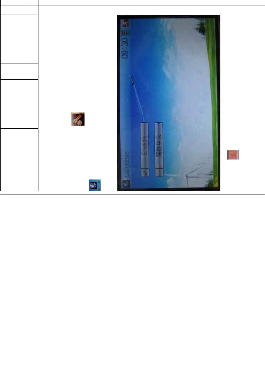
DEVO-8 Page no. Page 256 of 363
8D/R
exponential
icon
17
9 Model 18
1.1 Language setting
Touch the s hortcut icon to enter System Menu and then touch
to enter Language. Touch the language that you want to select. A
ĀĜ” will be shown on the screen after selected.
Then touch to save and exit.
1.2 Skin selection
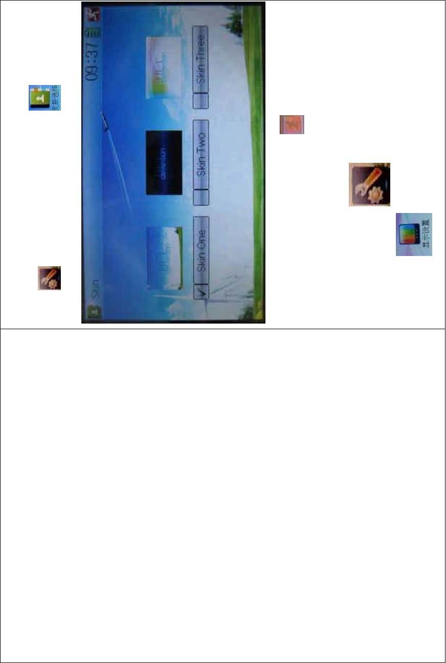
DEVO-8 Page no. Page 257 of 363
DEVO-8 offers three skins for your selection.
Touch to enter System Menu and touch to enter Skin.
Touch the skin yo u desire and then touch to exit.
1.3 Display
Touch the shortcut icon to enter System Menu and then
touch the icon to enter the DISPLAY INTERFACE.
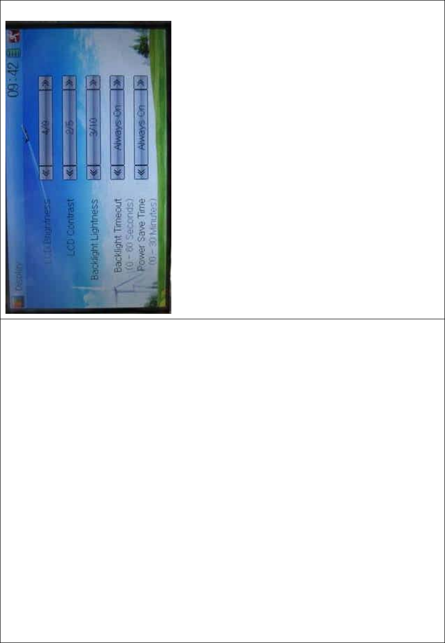
DEVO-8 Page no. Page 258 of 363
Five items are available to be set. Below are the setting methods for
them:
1) LCD brightness: it is possible to increase or decrease the LCD
brightness by touching the navigation marks. The power
consumption will be increased if the LCD is too bright and the
battery cruise duration will also be shortened.
2) LCD contrast: the contrast can be adjustable by touching the
navigation marks. The power consumption will be increased if the
contrast is too high and the battery cruise duration will be
shortened.
3) Backlight lightness: the backlight lightness can be adjustable by
touching the navigation marks. The power consumption will be
increased if the backlight lightness is too bright and the battery
cruise duration will be shortened.
4) Backlight time out: it is possible to set the duration which LCD stays
at highlight in the form of Always On and duration from 5 to 60
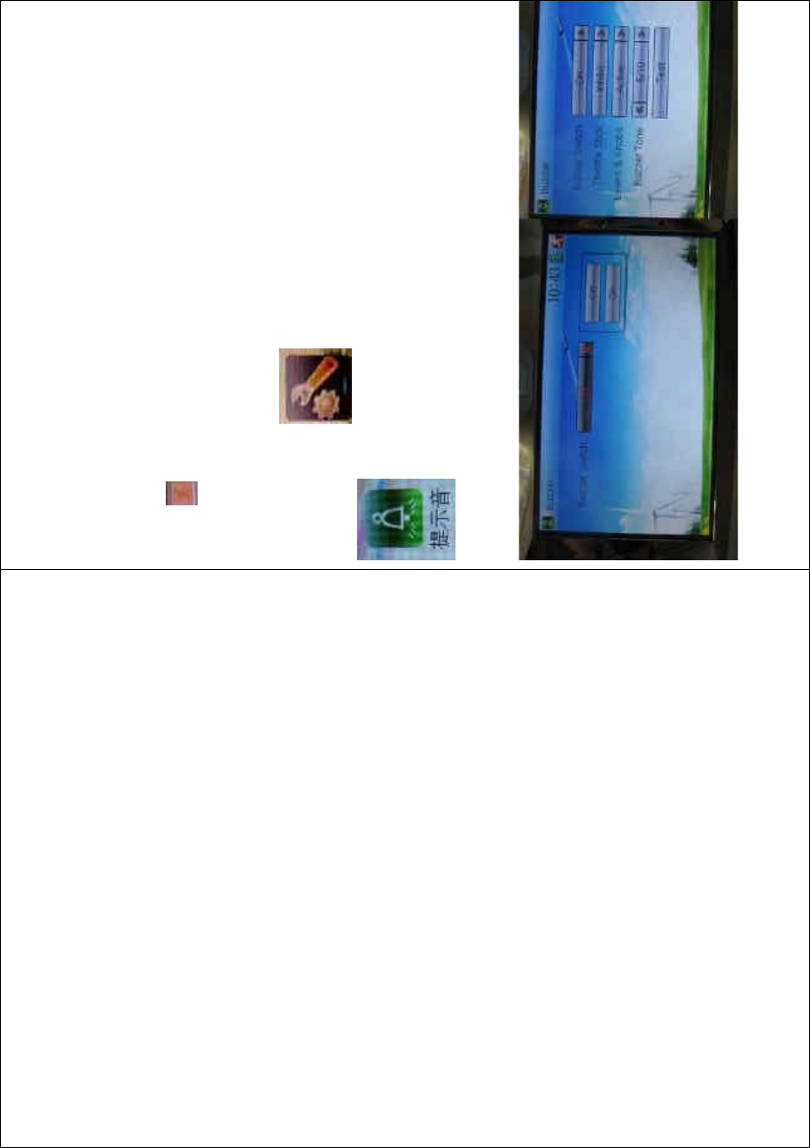
DEVO-8 Page no. Page 259 of 363
seconds with an interval of 5 seconds.
5) Power save time: it can adjust the backlighting duration by turning
off the backlight in order to prolong the battery cruise time. The
setting status contents Always On and duration in 30 grades with an
interval of 1 minute.
To uc h to exit.
1.4 Buzzer warning
To uc h t he i co n to enter System Menu and then touch
to enter Buzzer interface
1) Buzzer switch: touch the navigation mark at Buzzer Switch and pop
up an alternative item: Off and On. If touching On, a drop-down

DEVO-8 Page no. Page 260 of 363
menu will be shown below.
2) Spoiler stick: under Buzzer Switch is at the status of On, if Throttle
Stick is set as “Active”, a relative musical scale will make response
when moving the throttle stick. You can judge the position of the
throttle stick according to the different musical scales. Also, it can
be set as Inhibit.
3) Levers and knobs: under the condition that this item is set as
“Active”, DEVO-8 will sound when rotating or moving such levers or
knobs as AUX2, AUX3, AUX4, AUX5, AUX6, and AUX7 to their
neutralpositions.Itiscanbesetas“Inhibit”.
4) Buzzer tone: the tone is composed of 10 grades. You can choose
thefavoritetoneaccordingtoyourinterests.TouchTesttomakea
listening test.
To uc h to exit.
1.5 Date & Time
To uc h t he i co n to enter System Menu and then touch
to enter the DATE &TIME INTERFACE.

DEVO-8 Page no. Page 261 of 363
The clock setting is grouped into Year, Month, Day, and Time. Touch the
navigation marks, respectively, to make modifications.
To uc h to save and exit.
Note: if incorrect turn-on time or production time appears, one
possibility is that the power supply for the clock is not enough.
Replacing a new button cell is a must.
The method for changing button cell:
Turn off the power of your DEVO-8 and take off its battery pack. Use a
cross screwdriver to remove the two fixing screws on the fixing board.

DEVO-8 Page no. Page 262 of 363
English Your language
Fixing screws
Push outwards the button cell holder, and the button cell will
automatically pop up. Replace the old cell with a new one.
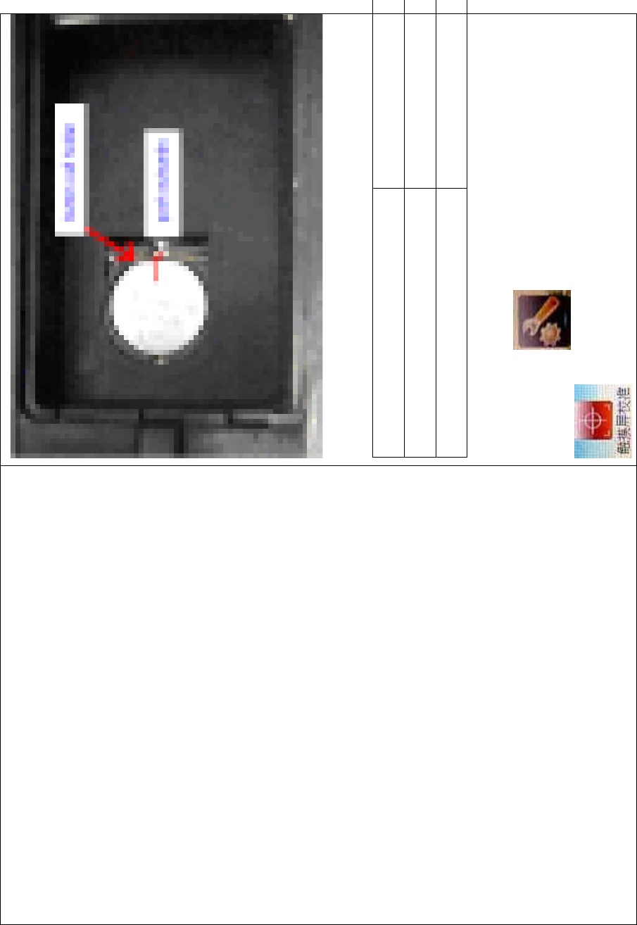
DEVO-8 Page no. Page 263 of 363
Cell size: CR 1220 3V
English Your language
Button cell holder
Push outwards
1.6 TFT screen calibration
To uc h t he i co n to enter System Menu and then touch
to enter the TFT SCREEN CALIBRATION

DEVO-8 Page no. Page 264 of 363
INTERFACE.
Click anywhere on the screen to start calibration with the touch pen,
and then follow the indication to calibrate. It will automatically return to
System Menu after the calibration is finished.
1.7 Stick mode
Touch the icon to enter System Menu, and then touch the
icon to enter Stick Mode.

DEVO-8 Page no. Page 265 of 363
There are four stick modes from MODE 1 to MODE 4. Select the stick
mode you desire and then to uch the icon to exit.
1.8 Stick and lever
To uc h t he ico n to enter System Menu and then touch the
icon to enter Stick and Lever. There are two items in the
interface: Stick Direction and Stick & Lever Calibration.

DEVO-8 Page no. Page 266 of 363
1) Stick direction: there are four options: Elevator, Aileron, Throttle,
and Rudder. Click the item, which you want to reverse, to change
the output direction of the stick. The default setting is Normal.
2) Stick & lever calibration: if variance happened in sticks or levers, it
wouldbecalibratedviathisoption.
Method for calibration:
Click the display item of Start to enter the status of calibration, and Start
will be turned into Stop.
2.1) Stick calibration: Clockwise or counter clockwise mechanically
move the right stick and left stick from their mi nimum levels to their
maximum levels several times, and then return the sticks to the neutral
positions, respectively.
2.2) Lever calibration: mechanically move the levers of AUX2, AUX3,
AUX4, and AUX5, respectively, from the minimum levels to the
maximum levels several times, and then return to the neutral positions,

DEVO-8 Page no. Page 267 of 363
respectively.
2.3) Click the display item of Stop. If the calibration is finished,
“Calibration success!” will be shown on the lower of the screen. If the
calibration is failed, “Calibration error! Please try again!” will be shown
instead. It needs to be calibrated again.

DEVO-8 Page no. Page 268 of 363
English Your language
Normal
Reverse
Stick direction
Stick & lever calibration
Start
Stop
Calibration success
Calibration error! Please try again!
2.4) Re-calibration: directly repeat the said steps 2.1 and 2.2 in the
calibration failure interface.
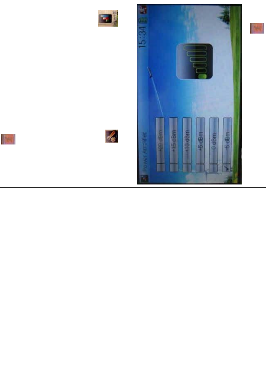
DEVO-8 Page no. Page 269 of 363
Touch the icon to exit.
1.9 Power amplifier
The transmission output power of DEVO-8 is adjustable. It is divided
into six grades from small to big. The lower the transmission output
power transmits, the nearer the radio range is, and the longer the
stand-by time will be. The higher the transmission output power, the
farer the radio range, and the shorter the stand-by time. Choose the
appropriate transmission output power according to the actual situation.
To uc h t h e i c o n to enter System Menu and then click to
enter the POWER AMPLIFIER INTERFACE.
Choose the appropriate output power level and then touch to exit.
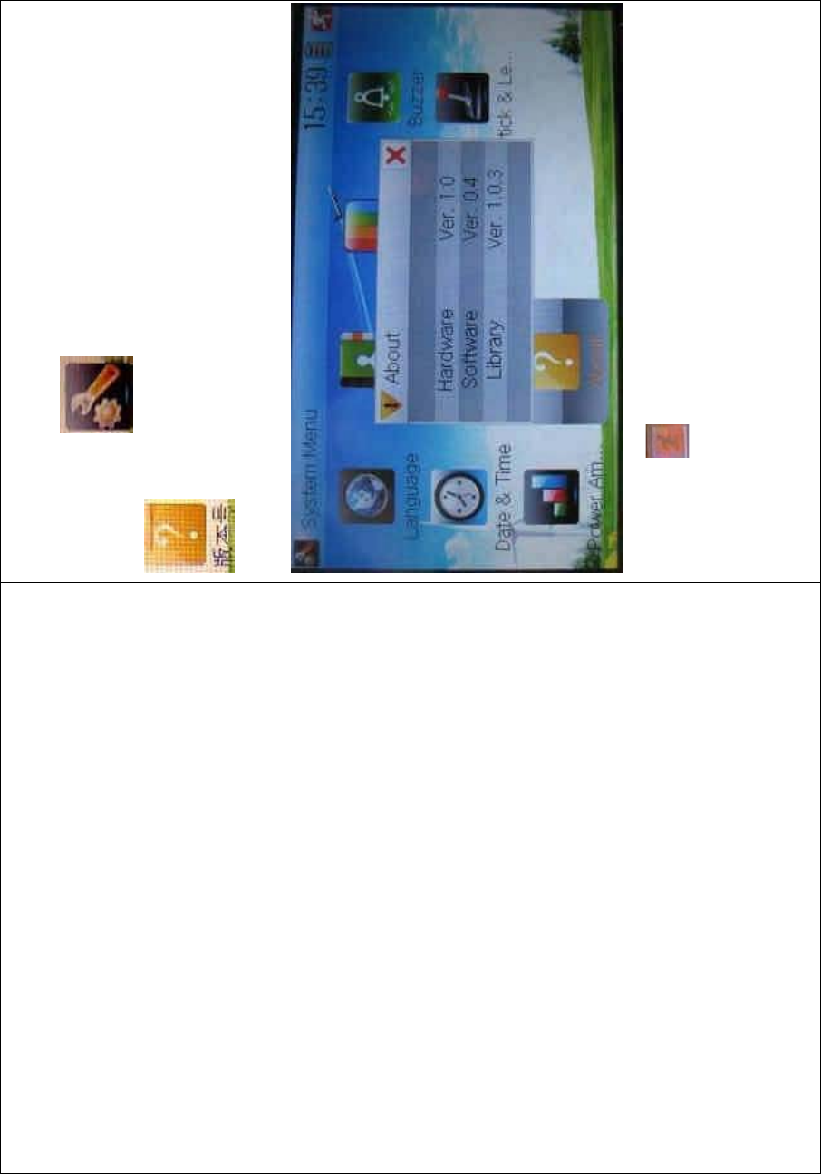
DEVO-8 Page no. Page 270 of 363
1.10 About
To uc h t he i co n to enter System Menu and then touch
to get access to the interface of About. You can check the
versions of hardware and software.
Click the icon to exit.
2.0 Model menu
Model Menu manages all the model data saved in DEVO-8. It includes
Model Select, Model Name, Model Copy, Model Transmit, Model
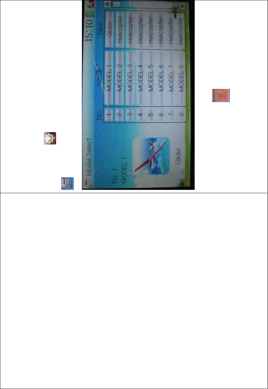
DEVO-8 Page no. Page 271 of 363
Receive, Model Reset, Type Select, Trim System, Stick Position,
Warning, Device Select, Device Output, Wing Type, and Fixed ID.
2.1 Model select
Touch the icon to enter Model Menu and then click the icon
to enter Model Select.
Touch the model you desire. The selected model is changed into
orange color. Then click the icon to exit.
2.2 Model name
In the menu of Model Name, you can make a desired name for your
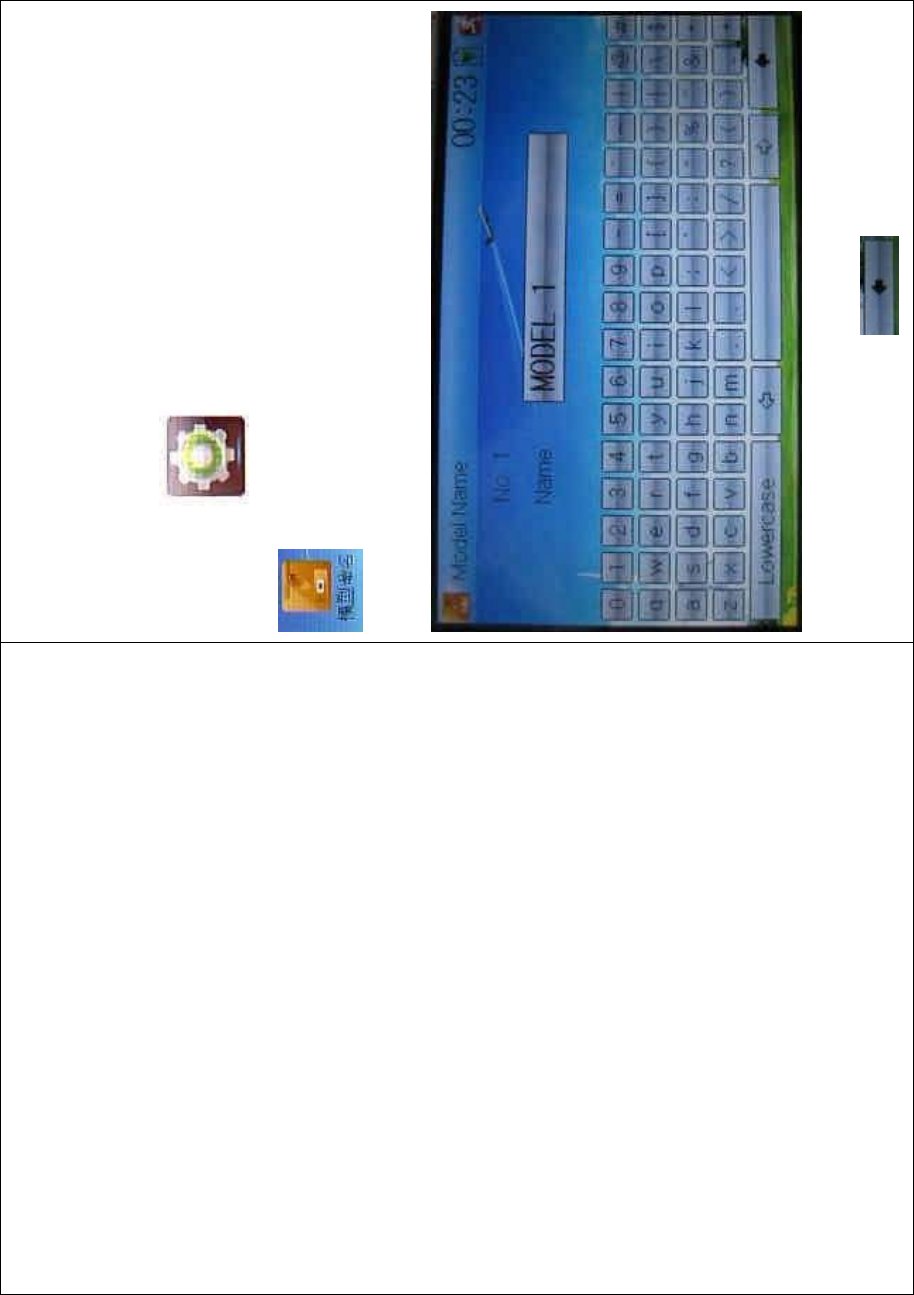
DEVO-8 Page no. Page 272 of 363
model for long term storage. Its data can be directly withdrawn in the
next f light.
Repeat the step “2.1 Model Select” to choose the model you want to
name or save.
Click the icon to enter System Menu and then click the icon
to get the MODEL NAME INTERFACE. The following is
the interface:
Click the right blank frame of Name and a gray stripe will be shown in
the frame. Touch the return key to clear up the old name.
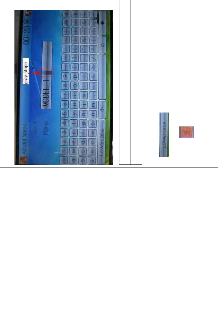
DEVO-8 Page no. Page 273 of 363
English Your language
Gray stripe
Touch the soft keyboard to input a new name. It is possible to switch
between lowercase and uppercase by clicking the
key .
Then touch to exit.
2.3 Model copy

DEVO-8 Page no. Page 274 of 363
Touch the icon to enter Model Menu and click to
enter the MODEL COPY INTERFACE.
Choose the model you want to be copied as source model. The serial
No. and model name of source model will be shown in the left side of
the interface.

DEVO-8 Page no. Page 275 of 363
Then touch the model in the right list where you want to locate the
source model. The serial No. and name of the model you chose will be
shown under Dest Model in the lower left of interface as well as an
enquire “Are you sure?” is popped up.
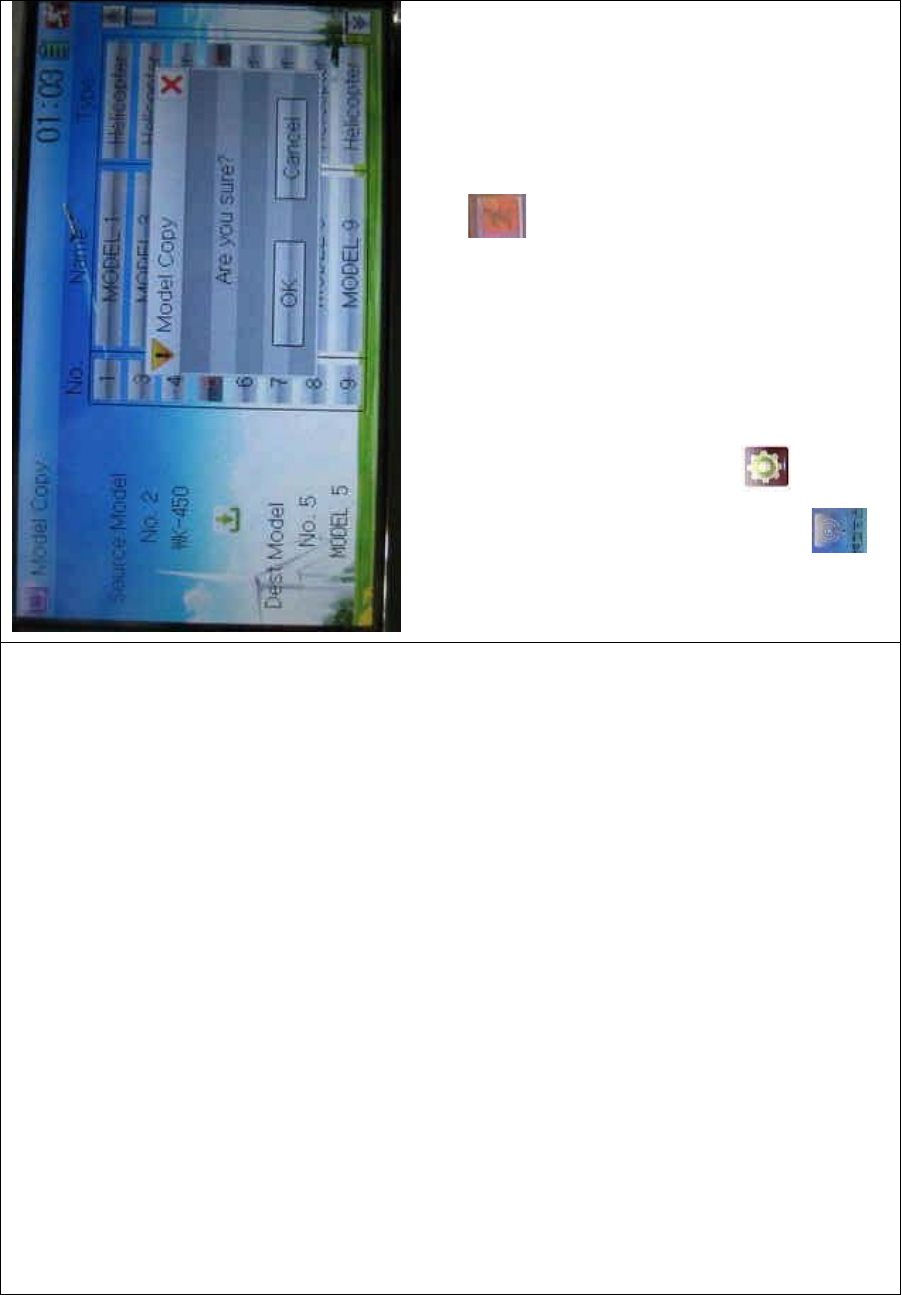
DEVO-8 Page no. Page 276 of 363
Click OK to copy. Otherwise click Cancel. Then the interface will be
automatically returned to Model Menu. Click to exit.
2.4 Model wireless copy
The model data between two DEVO-8 equipments can be wirelessly
copied via Model Transmit and Model Receive in Model Menu
1) Model transmission
Touch the icon to enter Model Menu and then continue to click
the icon to enter Model Transmit.
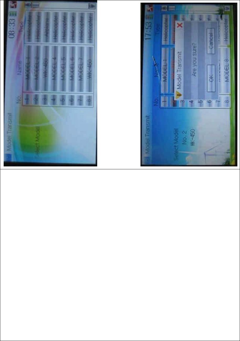
DEVO-8 Page no. Page 277 of 363
Choose the source model which will be transmitted. The serial No. and
name of the source model will be shown under Select Model in left side
of the interface as well as enquiry information “Are you sure?” in the
right side.
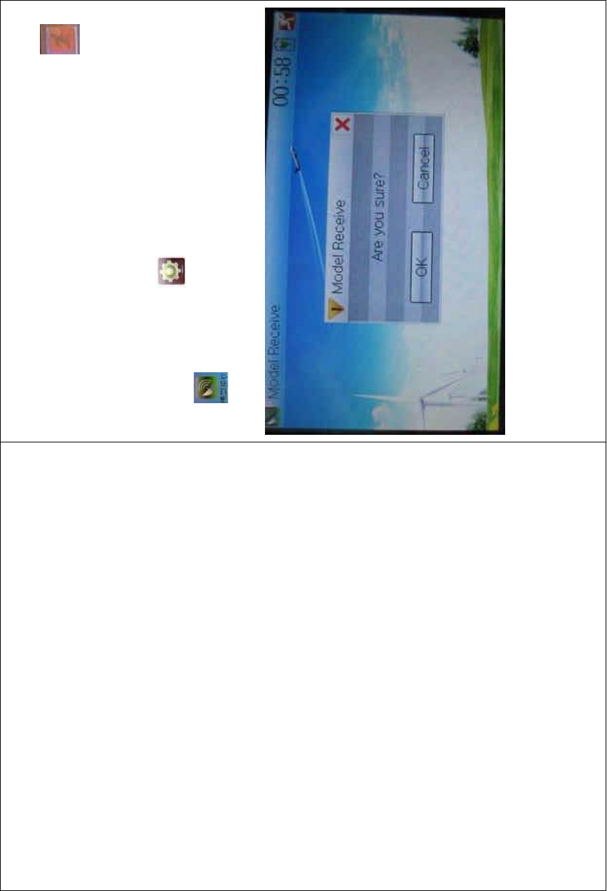
DEVO-8 Page no. Page 278 of 363
Click OK for transmission or Cancel for rejection. Enquiry information
“Transmitting ……” appears after clicking OK. Touch the icon to
exit.
2) Model receiving
Touch the shortcut icon to enter Model Menu and then touch the
icon to enter the MODEL RECEIVE INTERFACE. Enquiry
inf ormation “Are you s ure?” is s hown in the center of the interface.
Click Ok for receiving or Cancel for rejection. “Connecting ……” and
“Receiving ……” will be shown in series in the interface. The
information of “Received” with the model name will be shown in left side
after receiving is finished.

DEVO-8 Page no. Page 279 of 363
Choose the save position in the right name list by touching. Enquiry
information “Are you sure?” is shown after clicking the save position.
Click OK for save and the current interface will automatically return to
Mode Menu. Click Cancel for rejection.
Touch the icon to exit.
2.5 Model reset
All the model data can be restored to factory settings via Model Reset.
Touch the icon to e
nter Model Menu and then click
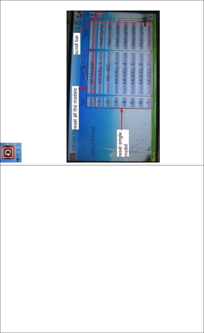
DEVO-8 Page no. Page 280 of 363
to enter Model Reset.
It is possible to store 60 models data in the model list of DEVO-8
equipment. There are two methods to reset the model data: batch reset
and single reset.
1) Method for batch reset:
Touch ‘All Models’ in Model Reset interface. Then ‘’All Models” and
enquiry “Are you sure?” appear in the left side. Click OK for reset, or
Cancel for rejection.
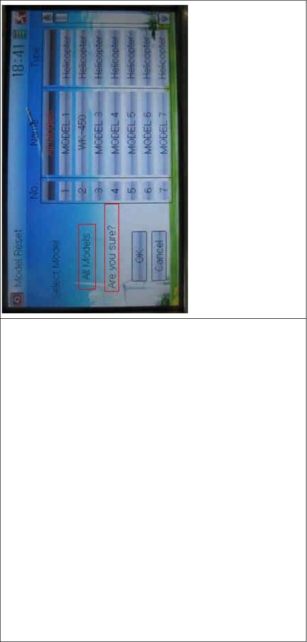
DEVO-8 Page no. Page 281 of 363
2) Method for single reset:
Touch the upper or lower navigation mark to move the scroll bar, and
then choose the model you want to restore in the model name list. The
selected model’s name and serial No., and enquiry “It is in use! Are you
sure?” appear in the left side. Click OK for reset, or Cancel for rejection.

DEVO-8 Page no. Page 282 of 363
Click the icon to exit.
2.6 Type select
This device offers three model types menu. They are helicopter,
airplane, and glider, respectively.
Touch the icon to enter Model Menu and then click
to enter Type Select.
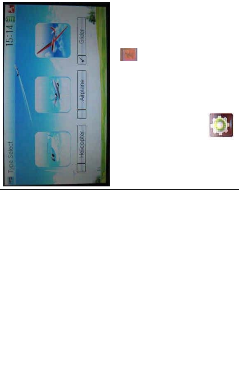
DEVO-8 Page no. Page 283 of 363
Choose the model type and then to uch the ico n to exit.
2.7 Trim system
Trim System is able to finely tune the following six items, respectively:
elevator, aileron, rudder, spoiler, left trim, and right trim. The trim range
is covered from 1 to 20 grades (factory default is set at 4). It is
convenient to subtly modify the pitch by adjusting the trim range.
Touch the icon to enter Model Menu and then click
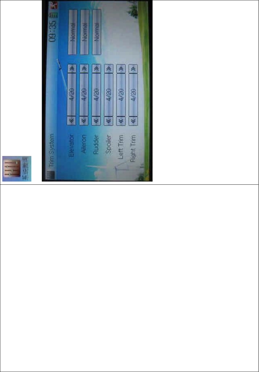
DEVO-8 Page no. Page 284 of 363
to enter Trim System.
Touch the corresponding navigatio n mark to change the trim value. The
bigger the trim value is, the bigger the trim range will be.
For elevator, aileron, and rudder, there are two more options: Normal
and Limited. “Normal” means the trim is always working although the
corresponding stick stays anywhere. “Limited” means the trim is out of
working when the corresponding stick is at maximum position.
2.8 Stick position
The stick can be used as a switch. The turn-on or turn-off position at
which the stick stays can also be set up.
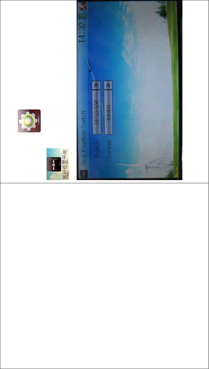
DEVO-8 Page no. Page 285 of 363
Method for setting:
Touch the icon to enter Model Menu and then click
to enter Stick Position Switch.
Click the navigation mark of Switch. It pops up a drop-down menu:
SPS0, SPS1, SPS2, and SPS3. Choose the switch you want to define.

DEVO-8 Page no. Page 286 of 363
Then touch the navigation mark of Channel. It expands into five items:
Inhibit Elevator, Aileron, Spoiler, and Rudder. The factory default setting
is Inhibit. Choose the stick you want to set as switch.
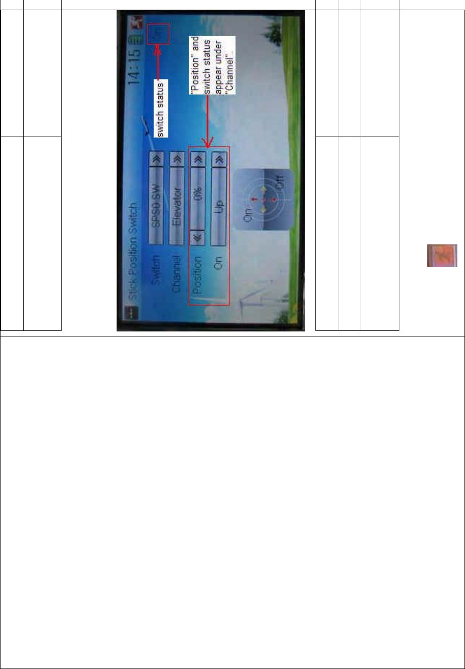
DEVO-8 Page no. Page 287 of 363
English Your language
Choose the channel which will be set as
switch.
At the same time, “Position” and the status of turn-on or turn-off appear
under the item Channel. The current status of turn-on or turn-off will be
shown on the right top corner.
English Your language
Switch status
“Position” and switch status appear under
“Channel”
Click the icon to exit after the setting finished.
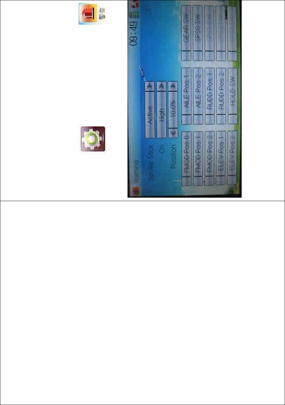
DEVO-8 Page no. Page 288 of 363
2.9 Warning
This function can set the warni ng f or unsafety of whic h stic k, switch
status, or flight mode stay at the position while turning on the device, or
is used as start-up warning on special purpose.
The factory default sets Spoiler Stick as Active, High direction at 10.0%
Position, set flight mode as Stunt, and set Throttle Hold at on position.
To uc h t he i co n to enter Model Menu and then click
to enter the WARNING INTERFACE.
Setting method:
1) setting Spoiler stick as warning
Click the navigation mark of Spoiler Stick in the interface Warning. It

DEVO-8 Page no. Page 289 of 363
expands into Inhibit and Active. If clicking Inhibit, the dropdown menu is
retracted. If clicking Active, it will expand into On and Position. It can set
the spoiler stick is at either high or low position when startup is warning.
Set the warning level by changing the percentage in Position, whose
setting value is ranged from 0.0 to 100.0%.
2) setting other items
Other flight modes and switches warning will be shown in the
lower-middle part of the interface after the setting for spoiler stick is
finished. Click the corresponding items you want to use.
Click to exit.
2.10 Device select
This setting can help you configure various functio nal switches, or
adjust levers. It includes Flight Mode Speed Switch, Flight Mode
Launch Switch, Launch Reverse, Aileron and Rudder Trims, Flap Trim
Select, and Flaperon Trim Select.
Friendly reminder: This function is f requently uti lized i n flights.
Modelers will be greatly favored if expertly mastering its usage.
Setting method:
Touch the icon to enter Model Menu, and then click the

DEVO-8 Page no. Page 290 of 363
icon to enter Device Select.
1) Flight mode speed switch
Touch the navigation mark of Flight Mode Speed Switch to expand into
a dropdown menu. Choose the mode switch you desire. The factory
default setting is Inhibit.
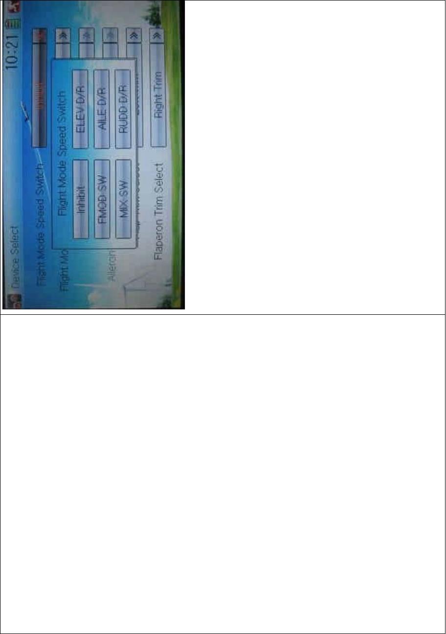
DEVO-8 Page no. Page 291 of 363
2) Flight mode launch switch
Refer to “1) Flight Mode Speed Switch”.
3) Launch reverse setting
Touch the navigatio n mark and pop up a list with two options: Normal,
and Reverse. Click Reverse for changing the current status. Flight
Mode Launch Switch should be previously activated before using this
functio n.
4) Aileron and rudder trims selection
There are two options: Common and Flight Mode. In Common option,
the adjustment parameter, of which the stick is corresponding to trim,
puts an equal effect on all the flight modes.
In Flight Mode, the adjustment parameter, of which the stick is
corresponding to trim, puts an respective effect on the corresponding
flight mode.

DEVO-8 Page no. Page 292 of 363
5) Flap trim select
Refer to “1) Flight Mode Speed Switch”.
6) Flap Trim Select
Refer to “1) Flight Mode Speed Switch”.
2.11 Device Output
Device output is composed of eight items. It can set up output switches
and select the usage of levers, respectively. It can also activate, inhibit
or use other functions.
Note: This function is frequently utilized in flights. Modelers will be
greatly favored if expertly mastering its usage.
Setting method:
Touch the icon to enter Model Menu and then click
to enter Device Output.

DEVO-8 Page no. Page 293 of 363
There are eight items to be adjustable. They are Motor, Flap, AUX2,
AUX3, AUX4, AUX5, AUX6, and AUX7. The setting methods for them
are shown below:
1) Motor
Touch the left column navigation mark of Motor and pop up an
expansion including FMOD SW, MIX SW, ELEV D/R, AILE D/R, RUDD
D/R, HOLD D/R, and GERA SW. Touch the desired item. The default
setting is GEAR SW.
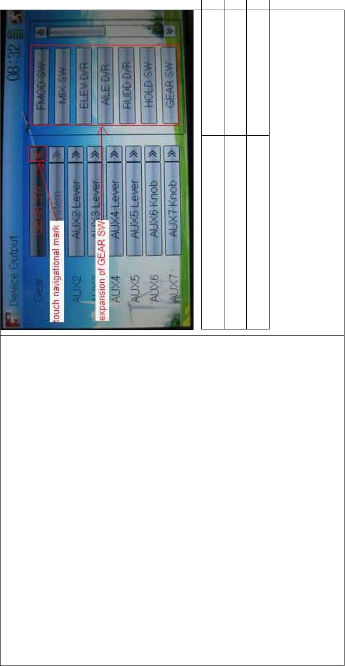
DEVO-8 Page no. Page 294 of 363
English Your language
Touch navigation mark
Expansion of GEAR SW
Touch the right column navigation mark of Motor. Pop up an expansion
list including Inhibit, Active, and Gyro. Touch the desired item. The
default setting is Active.

DEVO-8 Page no. Page 295 of 363
2) Flap
Touch the navigation mark of Flap at left column and expands a list
including AUX2 Lever, AUX3 Lever, AUX4 Lever, AUX5 Lever, AUX6
Lever, and AUX7 Lever. Select the desired item. The factory setting is
AUX2.
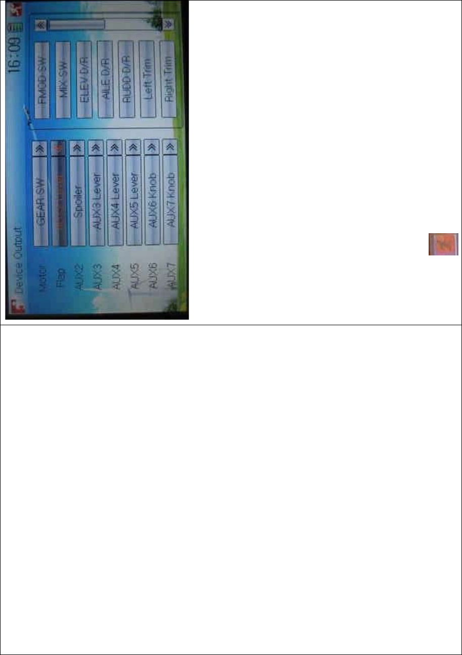
DEVO-8 Page no. Page 296 of 363
3) AUX 2
Refer to “2) Flap”.
4) AUX 3
Refer to “2) Flap”.
5) AUX 4
Refer to “2) Flap”.
6) AUX 5
Refer to “2) Flap”.
7) AXU6
Refer to “2) Flap”.
Click the icon to exit.
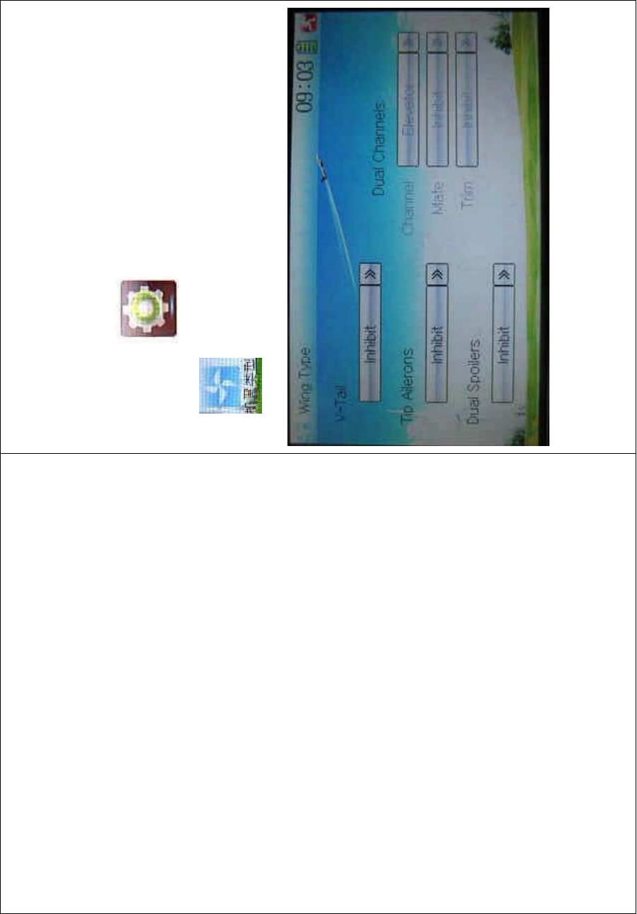
DEVO-8 Page no. Page 297 of 363
2.12 Wing type
The Wing Type includes V-Tail, Tip Ailerons, and Dual Spoilers.
Wing type selection:
Touch the icon to enter Model Menu, and then click the
icon to enter the WING TYPE INTERFACE.
1) V-Tail setting
Touch the navigation mark of V–Tail, and expand a sub menu includi ng
two options of Inhibit and Active. Select t he desired wing type. The
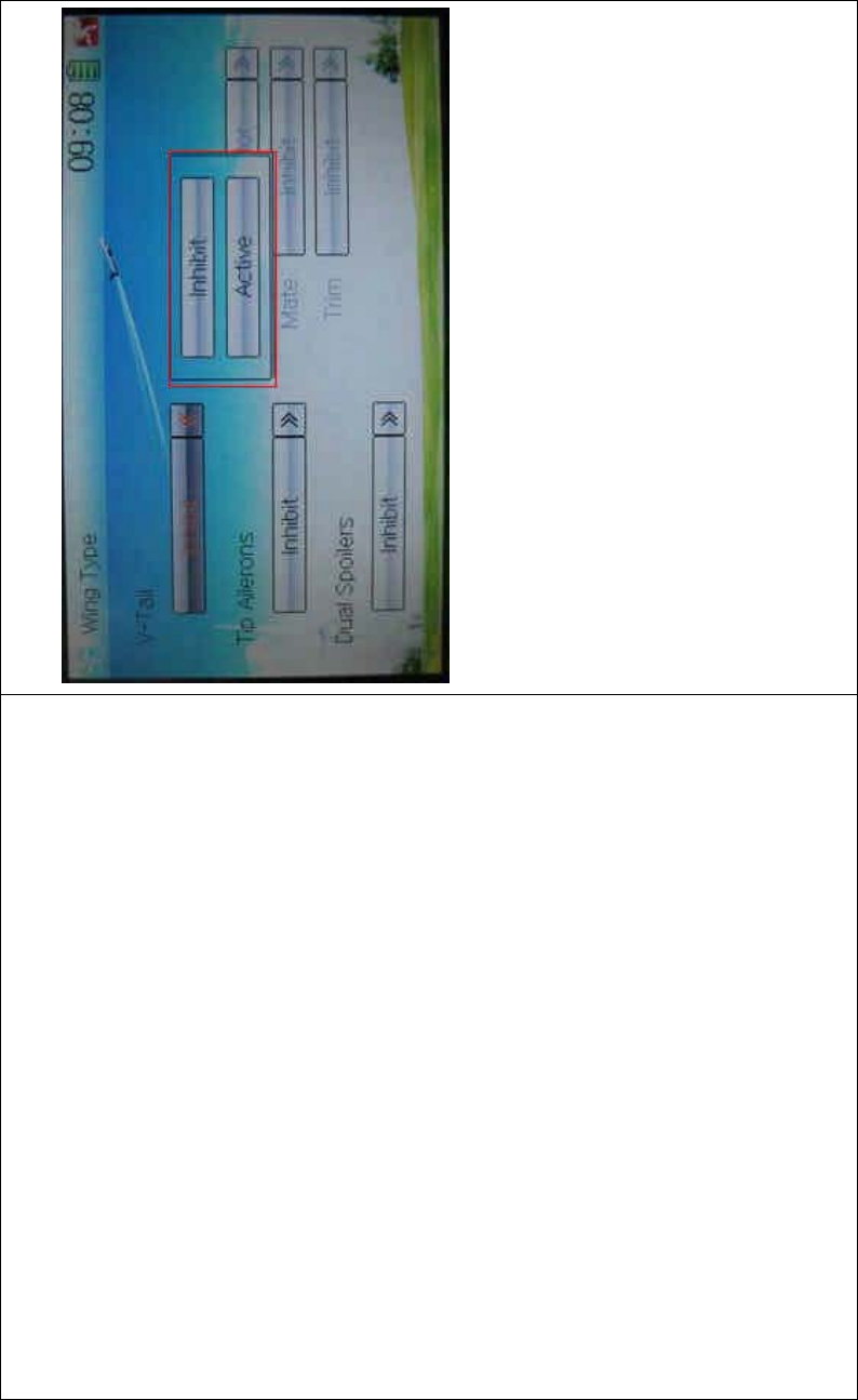
DEVO-8 Page no. Page 298 of 363
default setting is Inhibit.
2) Tip Ailerons setting
The setting is same as the above.
3) Dual Spoilers setting
The setting is same as the above.
4) Dual channels setting
It is possible to set elevator, rudder, and flap in dual channels, and is of
two-channel output function. The AUX channel, which will be used as
dual channels setting at Device Output in Model Menu, should be
previously set as Inhibit (Refer to “2.11 Device Output”).
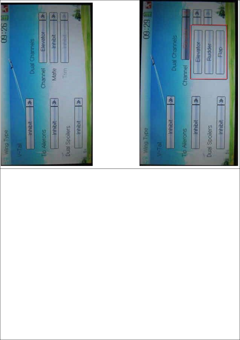
DEVO-8 Page no. Page 299 of 363
Setting method:
4.1) channel setting:
Touch navigation mark of Channel and expand a popup including
Elevator, Rudder, and Flap. Click the desired item.
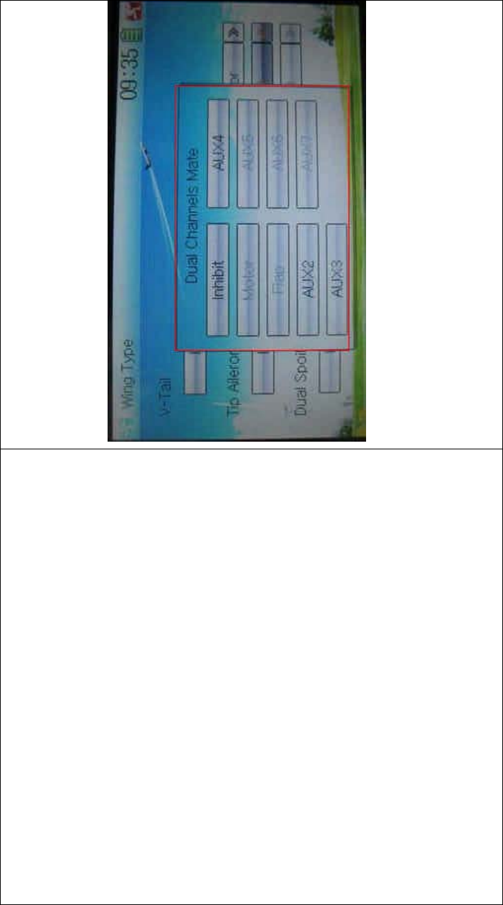
DEVO-8 Page no. Page 300 of 363
4.2) Mate setting
Touch the navigation mark of Mate and expand a popup with Inhibit and
the items shown at Device Output. Select the desired item. Note: the
selected channels are shown in grey and are not selectable.
4.3) Trim setting
Touch the navigation mark of Trim and expand a popup i nc luding
Inhibit, Left Trim, Right Trim, AUX2 Lever, AUX3 Lever, AUX4 Lever,
AUX5 Lever, AUX6 Knob, and AUX7 Knob. Select the item you want to
use.
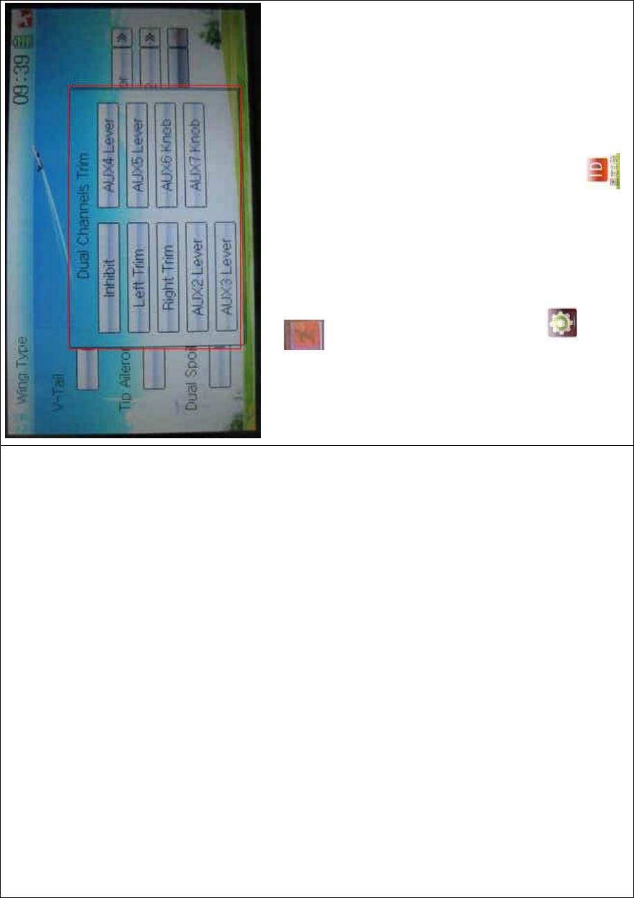
DEVO-8 Page no. Page 301 of 363
Click the icon to exit.
2.13 Fixed ID
This setting will bind DEVO-8 and its receiver in a unique corresponding
relationship. It will greatly speed up the time of automatic binding when
DEVO-8 powered on.
3) Setting for fixed ID
The setting for fixed ID should be under the status that automatic ID
binding is successfully finished. Below is the setting method.
Touch the icon to enter Model Menu in the main interface, and
then enter Fixed ID by touching the icon in Model Menu.

DEVO-8 Page no. Page 302 of 363
English Your language
Navigation mark
Touch the navigation mark of the item ID Code Setting. It will expand
into two OPTIONS: Off and On. A series of random digits will be
shown below after touching On.

DEVO-8 Page no. Page 303 of 363
English Your language
To uc h “O n”
A series of random digits is shown here
A mini soft keyboard is shown in t he lower part after touc hi ng the
random digits of ID Code

DEVO-8 Page no. Page 304 of 363
English Your language
Mini soft keyboard
The new ID digits can be modified by touching the mini soft keyboard.
Touch Match after the new ID is already set. An enquiry interface of “Are
you sure?” pop up. “ID Code Match … …” will be shown after touching
OK.

DEVO-8 Page no. Page 305 of 363
English Your language
ID Code Setting
ID Code
Fixed ID
Are you sure?
Cancelled
ID Code Match
4) Fixed ID cancellation
Insert the assorted BIND PLUG into the output terminal of BATT before
the receiver is powered on, and then plug 5V DC power into other
output terminal. The red light of receiver will flash slowly. This means
the fixed ID code has been cancelled. Pull out BIND PLUG.

DEVO-8 Page no. Page 306 of 363
DEVO-8 also needs to make relative cancellation and reversion after
the fixed ID in receiver is cleared out.
In the mai n interface touch the icon to enter Model Menu and
then touch to enter Fixed ID. Touch ID Code Setting to expand
the navigation mark into two statues On and Off. Touch Off. Then touch
to exit.
3.0 Function menu
Function Menu is used to make a personalizedly fine adjustment to the
selected models. It includes Reverse Switch, Travel Adjust, Sub Trim,
Dual Rate and Exponential, Motor Hold, Flaperon Mix, Camber System,
Differential, Balance, Gyro Sensor, Rudder to Spoiler Mix, Aileron to
Rudder Mix, Elevator to Flap Mix, Aileron to Flap/ Wingtip Mix, Flap
Rate, Brake System, Program Mix, Monitor, Fail Safe, Trainer, and
Timer.
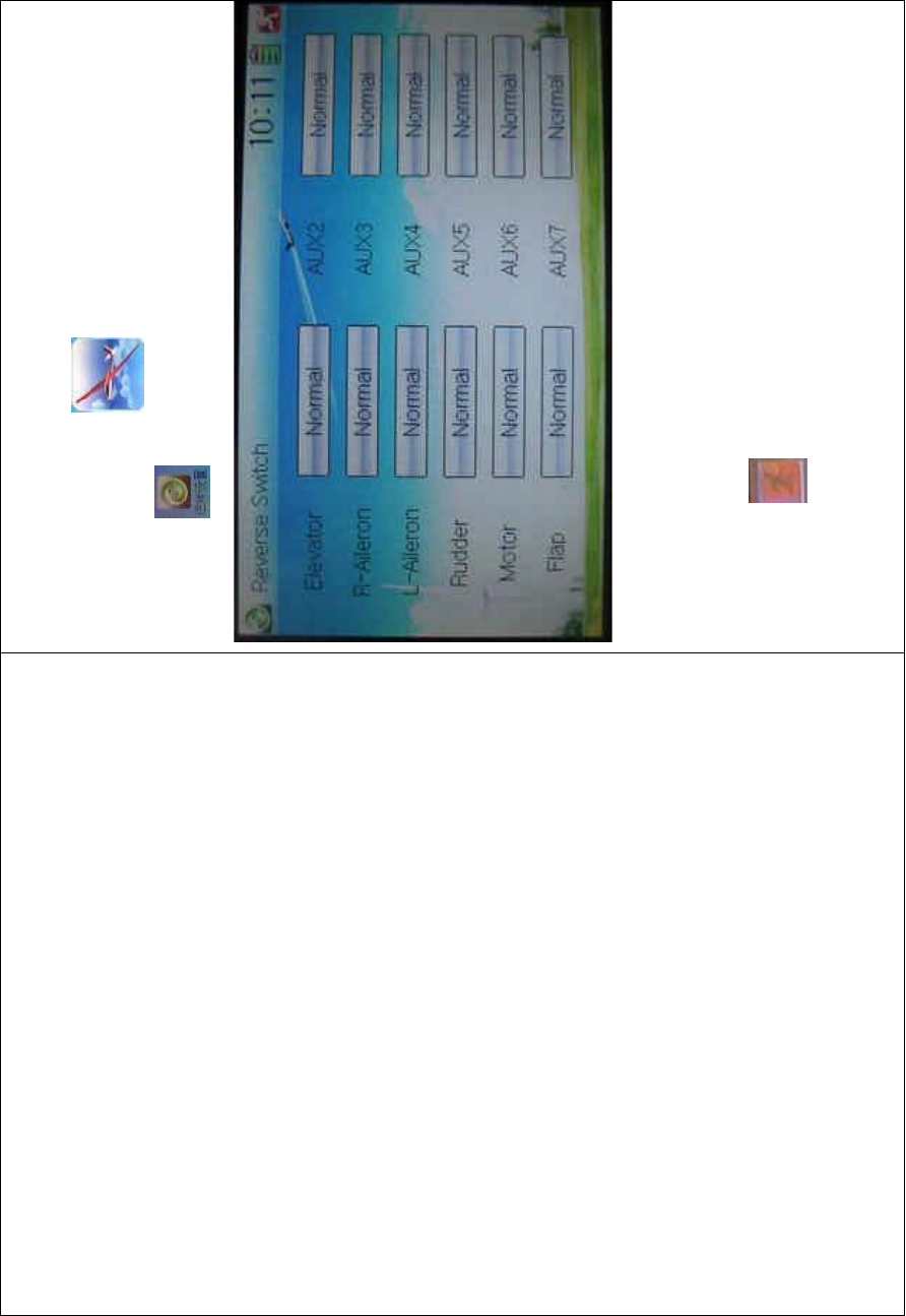
DEVO-8 Page no. Page 307 of 363
3.1 Reverse switch
Touch the shortcut icon to enter Function Menu, and then
click the icon to enter the interface of Reverse Switch.
There show all the reverse switches’ statuses of twelve channels. Touch
the desired item to reverse its current status. The status includes two
types: Normal and Reverse. The default setting is Normal.
Touch the icon to exit after finished.
3.2 Travel adjust
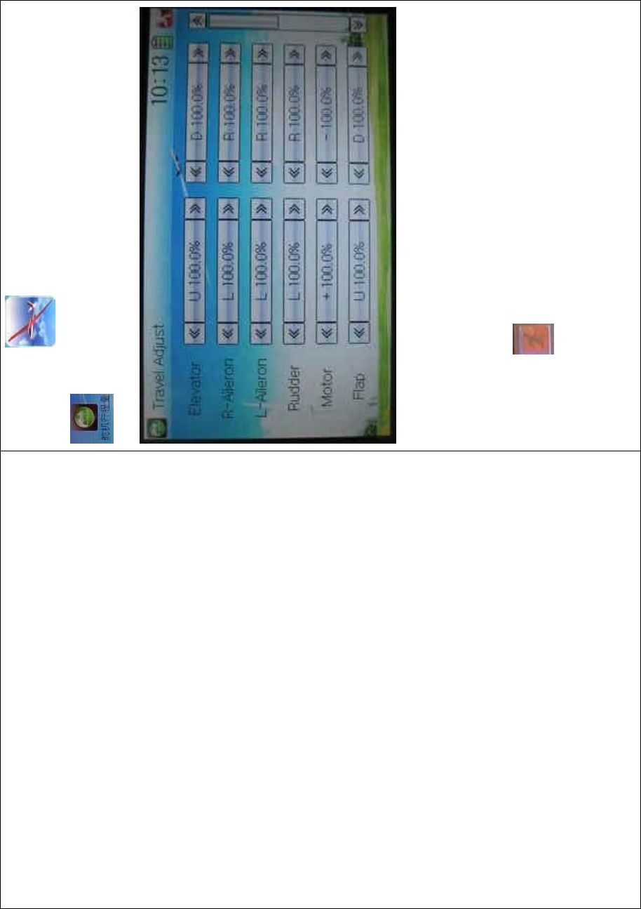
DEVO-8 Page no. Page 308 of 363
To uc h t he ico n to enter Function Menu and then click the icon
to enter the SERVO ADJUST INTERFACE.
The interface contents two pages to show the current travel status of all
the twelve channels. Touch the navigation mark of each item to
increase or decrease corresponding travel adjustment amount. The
adjustable range is 0.0-150.0%. The default setting is 100.0%.
Click the icon to exit after finished.
3.3 Sub trim
Sub Trim is used to make parallel movement of servos. It is
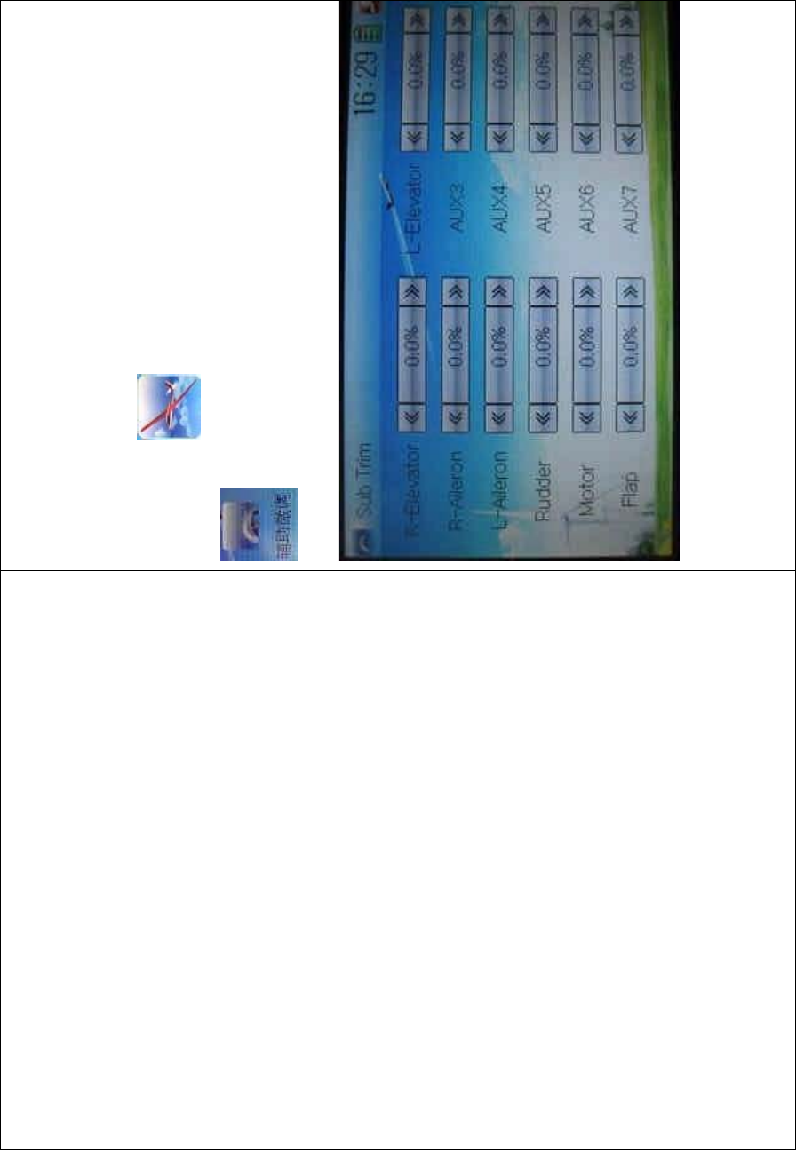
DEVO-8 Page no. Page 309 of 363
recommended to adjust the servo bell crank if the servo is far away from
its neutral point. The excessive usage of sub trim may damage the
servo.
Setting method:
To uc h t he ico n to enter Function Menu and then click the icon
to enter the SUB TRIM INTERFACE.
Touch the navigation mark of the desired item to adjust the amount for
rectifying the servo’s neutral point. The default neutral point is set at
0.0%. The adjustment range of each channel is shown as below:
DEVO-8 Page no. Page 310 of 363
English Your language English Your la
Channel name Adjustment range
R-elevator D62.5%-U62.5%
R-aileron R62.5%-L62.5%
L-Aileron RL62.5%-LH62.5%
Rudder R62.5%-L62.5%
Motor -62.5%- +L62.5%
Flap DL62.5%- UH62.5%
L-elevator D62.5%- U62.5%
AUX3 -62.5%- +62.5%
AUX4 -62.5%- +62.5%
AUX5 -62.5%- +62.5%
AUX6 -62.5%- +62.5%
AUX7 -62.5%- +62.5%
Note: the model names shown will be different with the selected
channels different.
Click the icon to exit after finished.
3.4 Dual rate and exponential
It is possible to use D/R switch to control over the dual rate of elevator,
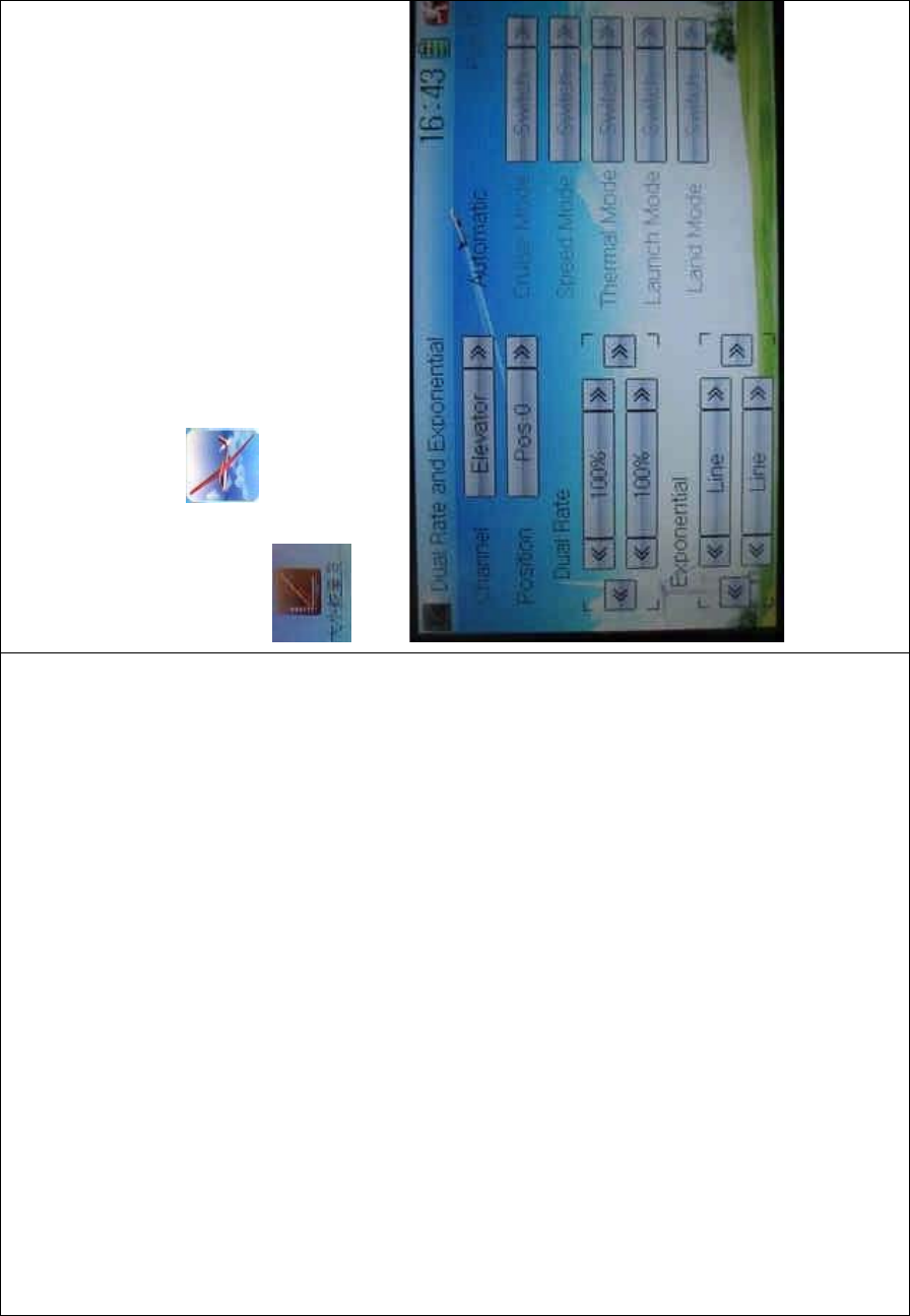
DEVO-8 Page no. Page 311 of 363
aileron, and rudder after the function of Dual Rate and Exponential is
set up. The setting range is 0-125%. Under the help with exponential
curve adjustment, it is not only manually but also automatically to set up
various parameters which are suitable for yourself.
Setting method:
To uc h t he ico n to enter Function Menu and then click the icon
to enter the DUAL RATE AND EXPONENTIAL
INTERFACE.
1) Channel selection
Touch the navigation mark of Channel and expand a selectable list
including Elevator, Aileron, and Rudder. Click the desired channel which
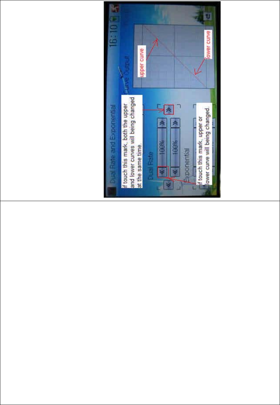
DEVO-8 Page no. Page 312 of 363
will be shown in Channel.
2) Position selection
Touch the navigation mark of Position and expand a selectable list
including Pos 0, Pos 1, Pos 2, Pos 3, and Pos 4. Click the desired item
which will be shown in Position. There will only show Pos 0, Pos 1, and
Pos 2 in manual setting.
3) Dual Rate adjustment
Itispossibletomodifythevaluebytouchingthenavigationmarkof
Dual Rate.
If touchi ng the navigatio n mark for just one item to amend the dual rate
value, the dual rate of the correspondi ng servo wi ll be changed in one
direction, while the curve will being changed in one direction at the right
graph.
If touching the navigation mark for both items to amend the dual rate
value, the dual rate of the corresponding servo will be changed while

DEVO-8 Page no. Page 313 of 363
the curve will being changed at the same time, shown at the right graph.
The default setting is 100%.
English Your language
Upper curve
Lower curve
If touch these marks, both the upper and
lower curves will being c hanged at t he
same time.
IF YOU USE THIS MARK B
O
AND LOWER CURVES
CHANGED.
If touch these marks, either upper or
lower curve will being changed.
Upper curve
Lower curve
4) Expo nential adjustment
It is possible to adjust the exponential output value of the servo at that
point, which is set up in step “2) Position selection”, by touching the
navigation mark of Exponential.

DEVO-8 Page no. Page 314 of 363
If touching the navigation mark of just one item to amend the dual rate
value, the dual rate of the correspondi ng servo wi ll be changed in one
direction, while the curve will being changed in one direction at the right
graph.
If touching the navigation mark of both items to amend the dual rate
value, the dual rate of the corresponding servo will be changed while
the curve will being synchronously changed, shown at the right graph.
The default setting is Line.
Then to uc h this mark to return to the interface of Dual Rate and
Exponential.
5) Automatic setting
Under working with Flight Mode, it is possible to switch between the
dual rate and exponential, which are set in above “3) Dual Rate
adjustment” and “4) Exponential adjustment”, respectively. It includes
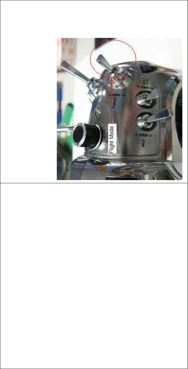
DEVO-8 Page no. Page 315 of 363
Cruise Mode, Speed Mode, Thermal Mode, Launch Mode, and Land
Mode.
Note: if want to use this functio n, it is necessary to previously set both
Flight Mode Speed Switch and Flight Mode Launch Switch at Device
Select in Model Menu as the corresponding switches. Refer to “2.10
Device Select”.
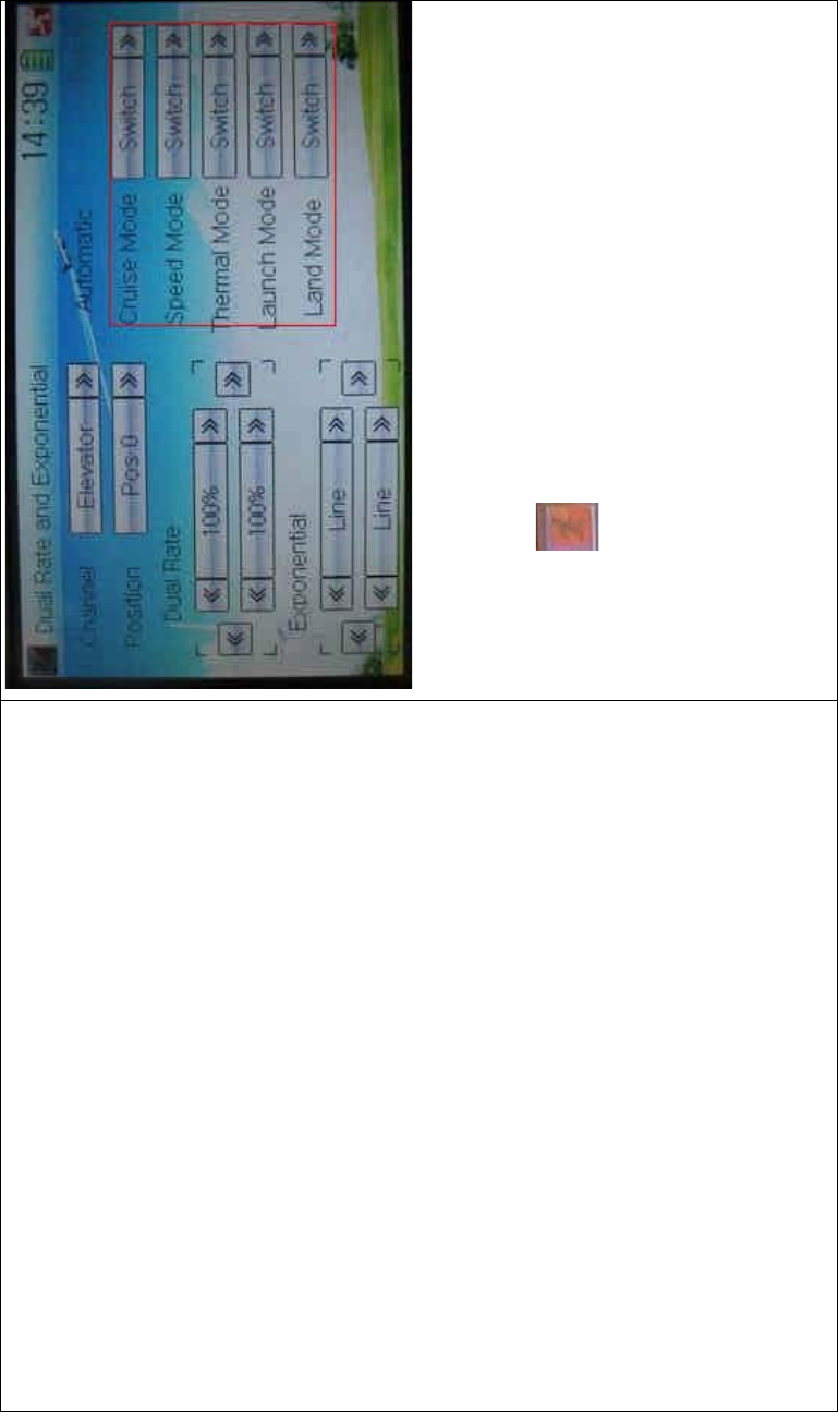
DEVO-8 Page no. Page 316 of 363
Touch the navigation mark of the desired item and expand a popup with
the selectable positions. Select the position you desire. And then this
switch is only controlled by the corresponding D/R lever.
Click the icon to exit.
3.5 Motor hold
Themotorholdcanbeswitchedafterthefunctionisused.Thesetting
range of motor hold is from -10% to 100%. The item Motor should be
previously set at Device Output in Model Menu, which is used as
Spoiler Stick and is activated. Refer to “2.11 Device Output”.
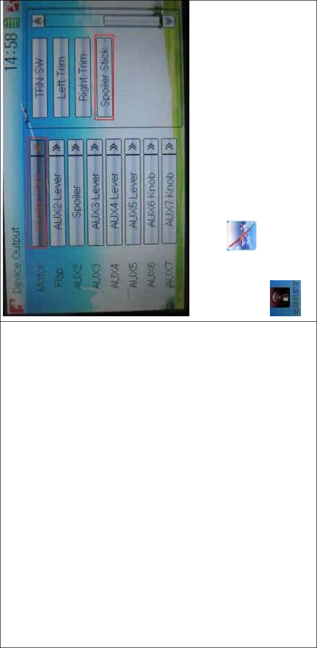
DEVO-8 Page no. Page 317 of 363
Setting method:
To uc h t he i co n to enter Function Menu, and then click the icon
to enter the interface of Motor Hold.
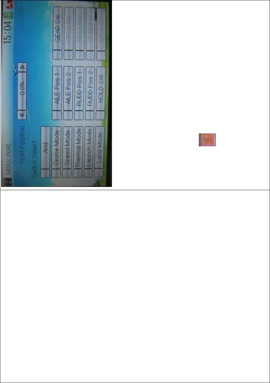
DEVO-8 Page no. Page 318 of 363
1) Hold Position setting
Touch the left or right navigation mark of Hold Position to decrease or
increase, respectively, the amount. The adjustable range is from -10.0%
to 100.0% and the default setting is 0.0%.
2) Switch select
7RXFKWKHVZLWFK\RX ZDQWDQG D³¥´ZLOOEHVKRZQLQLWV OHIW,IWZRRU
more switches are chosen, the item And should be selected.
Touch the icon to exit.
3.6 Flaperon mix
This function is used to mix Aileron to Flaperon, or mix Elevator to
Flaperon. The mix amount can be independently set in each flight
mode.
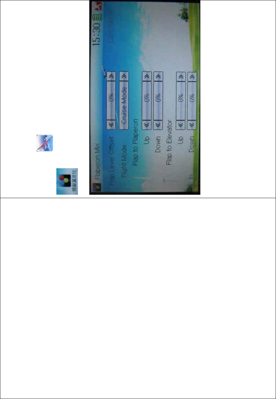
DEVO-8 Page no. Page 319 of 363
The flap rate in each flight mode should be previously set before using
this function. Refer to the following “3.16 Flap rate”.
Setting method:
Touch the icon
to enter Function Menu, and then click the icon
to enter the FLAPERON MIX INTERFACE.
1) Flap Lever Offset setting
This function can be used to set the neutral points of Flaperon servos.
Touch the left or right navigation mark of Flap Lever Offset to decrease
or increase amount, respectively. The adjustable range is ±100%. It is
possible to change the offset direction by changi ng t he sign before the
amount.
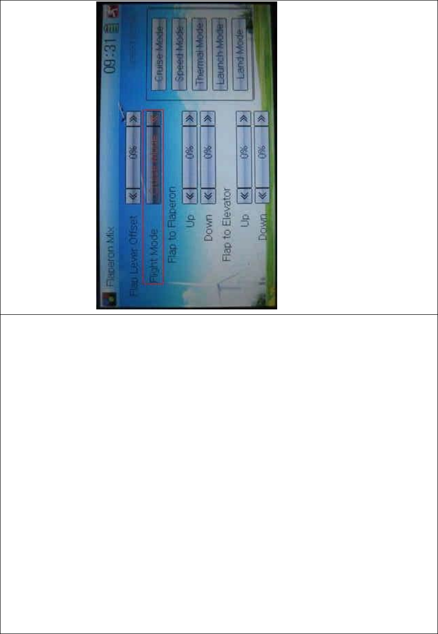
DEVO-8 Page no. Page 320 of 363
2) Flight Mode setting
Flight Mode at Device Select should be previously chosen before using
this function (Refer to “2.10 Device Select”).
Touch the navigation mark of Flight Mode to select the desired item in
the following popup list.
2.1) Flap to Flaperon
Touch the navigation mark of Up or Down to change the Flaperon mix
value when moving the Flaperon stick. The bigger the value is, the
bigger mix will be. The adjustable mix is ranged from -125% to + 125%.
It is possible to alter the Flaperon mix direction by altering the sign
before the value.
2.2) Flap to Elevator
Touch the navigation mark of UP or Down to change the elevator mix
value when moving the Flaperon stick. The bigger the value is, the

DEVO-8 Page no. Page 321 of 363
bigger the mix will be. The adjustable mix is ranged from -125% to +
125%. It is possible to alter the elevator mix direction by changing the
sign before the value.
Touch the icon to exit.
3.7 Camber system
This function can change both the flap angle and aileron angle, which
goes through the central line of the main wings’ transect, and then
change the features of main wings. It can be independently set in each
flight mode.
Setting method:
Touch the icon to enter Function Menu, and then click the icon
to enter the CAMBER SYSTEM INTERFACE.

DEVO-8 Page no. Page 322 of 363
1) Flight Mode setting
Theflightmodeshouldbepreviouslyactivatedin“DeviceSelect”before
using this function (refer to “2.10 Device Select”).
Touch the navigation mark of Flight Mode and expand a popup, where
you can select the desired flight mode.
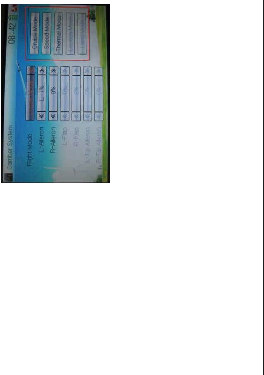
DEVO-8 Page no. Page 323 of 363
2) L- or R-Aileron setting
Touch the navigatio n mark of L- or R-Aileron to change the position of
L-aileron or R-aileron with a range of ± 100%. It is possible to alter the
direction of L- or R-aileron via changing the letter of “R” or “L” before the
amount.
3) L- or R-Flap setting
The flap dual channels should be previously set in Wing Type (refer to
“2.12 Wing Type”).
Touch the navigation mark of L- or R-Flap to change the position of L- or
R- Flap with a range of ± 100%. It is possible to alter the direction of L-
or R-aileron via changing the letter of “R” or “L” before the amount.
4) L- or R-Tip Aileron setting
The tip aileron should be previously set at Wing Type (refer to “2.12

DEVO-8 Page no. Page 324 of 363
Wing Type”).
Touch the navigatio n mark of L- or R-Aileron to change the position of
L- or R-aileron with a range of ± 100%. It is possible to alter the
direction of L- or R-aileron via changing the letter of “R” or “L” before the
amount.
Click the icon to exit.
3.8 Differential
1) Flight mode setting
The flight mode should be previously set in Device Select (refer to “2.10
Device Select”).
Touch the ico n to enter Function Menu, and then click
the icon to enter the DIFFERENTIAL INTERFACE.
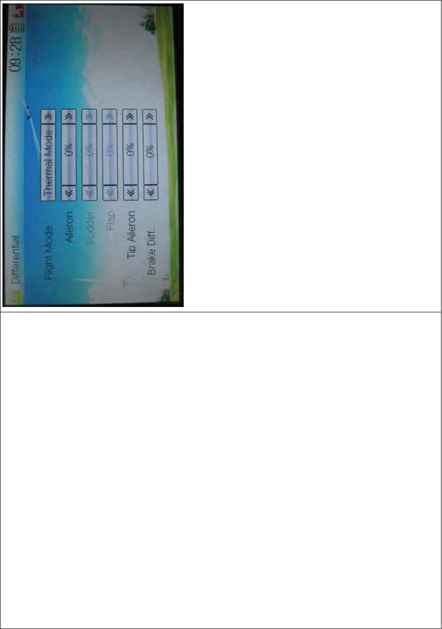
DEVO-8 Page no. Page 325 of 363
1.1) Aileron differential setting
It is possible to decrease the vibration to the head from reverse
direction in operating aileron.
Touch the left or right navigation mark of Aileron to decrease or
increase, respectively, the value with a range of ± 100%. The bigger the
value is, the bigger the differential will be
1.2) Rudder differential setting
In this function, the left or right rudder in V Tail will produce differential
gearshift. V-Tail should be previously set in Wing Type at Model Menu
(refer to “2.12 Wing Type”).
Touch the left or right navigation mark of Rudder to decrease or
increase, respectively, the value with a range of ± 100%. The bigger the
value is, the bigger the differential will be.
1.3) Flap differential setting

DEVO-8 Page no. Page 326 of 363
Flap Dual channels should be previously set at Wing Type in Model
Menu (refer to “2.12 Wing Type”).
Touch the left or right navigation mark of Flap to decrease or increase,
respectively, the value with a range of ± 100%. The bigger the value is,
the bigger the differential will be.
1.4) Tip Aileron setting
Tip Aileron should be previously set at Tip Aileron in Model Menu (refer
to “2.12 Wing Type”).
Touch the left or right navigation mark of Tip Aileron to decrease or
increase, respectively, the value with a range of ± 100%. The bigger the
value is, the bigger the differential is.
2) Brake differential
If co-working with the spoiler stick, the brake differential function can
counteract the differential.
Touch the left or right navigation mark of Brake Differential to decrease
or increase, respectively, the value with a range from 0% to 100%. The
bigger the value is, the bigger the differential will be.
Click the icon to exit.
3.9 Balance
This function can adjust the two-servo parameters, which are
simultaneously used in dual output channels, but “Dual Channels”
should be previously activated at Wing Type in Model Menu (refer to
“2.12 Wing Type”).
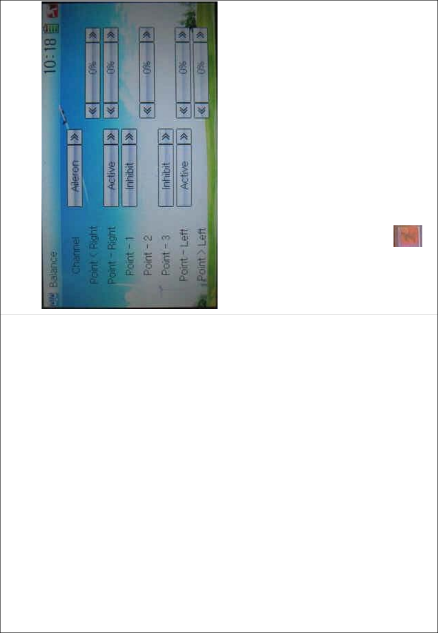
DEVO-8 Page no. Page 327 of 363
Touch the icon to enter Function Menu, and then click the icon to enter
the interface of Balance.
1) Channel selection
Touch the navigation mark of Channel and expand a sub menu and
select the desired item.
2) Point setting
Touch the navigation mark of the point whic h you want to adjust, and
expand a sub menu with Inhibit and Active. Click Active for adjusting,
and then touch its navigation mark to change the value with a range of ±
100%. The default setting is 0%. The minus value means the amending
direction is downward, and the plus value means upward.
Click the icon to exit.
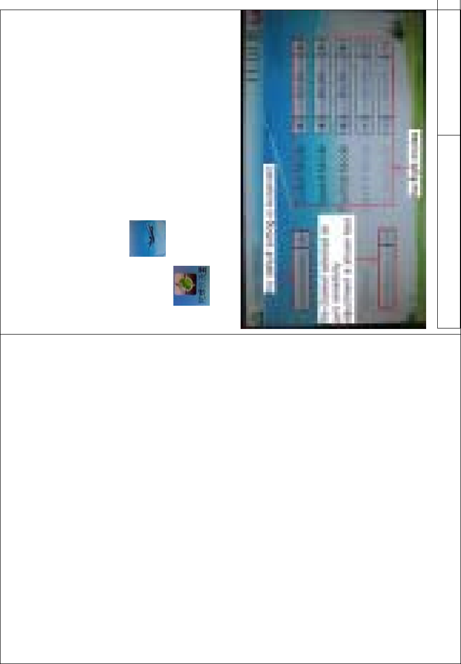
DEVO-8 Page no. Page 328 of 363
3.10 Gyro sensor
This function offers the gain adjustment for gyro sensor. It is possible to
be automatically switched among various gains via flight mode, which
should be previously set at Device Select in Model Menu (refer to “2.10
Device Select”), and the gyro output should also be simultaneously set
at Device Output (refer to “2.11 Device Output”).
Setting method:
Touch the icon to enter Function Menu, and then touch the
icon to enter the GYRO SENSOR INTERFACE There
show Automatic setting mode, output channel, and five flight modes.
English Your language
DEVO-8 Page no. Page 329 of 363
The default setting is Automatic
The channel selected as gyro gain
adjustment is shown here
Five flight modes
Setting method for flight mode:
Touch the left or right navigation of the flight mode, which you want to
adjust, to decrease or increase, respectively, the value with a range of
0.0% - 100.0%.
If the gyro used has two modes of NOR and AVCS, NOR will be
activated when the value is less than 50.0%, and AVCS activated when
above 50.0%. In NOR mode, the smaller the value is, the bigger the
gain will be; in AVCS mode, the bigger the value is, the bigger the gyro
sensor gain will be. The factory setting is 50.0%.
Touch the icon to exit.
3.11 Rudder to spoiler mix
When this function is activated, the spoiler can be used as rudder in the
models without rudder and can also be mixed. The mix gain can be
independently set in each flight mode, which should be previously set at
Device Select in Model Menu (refer to “2.11 Device Select”), and “Dual
Spoilers” should also be activated at Wing Type (refer to “2.12 Wing
Type”).
Setting method:
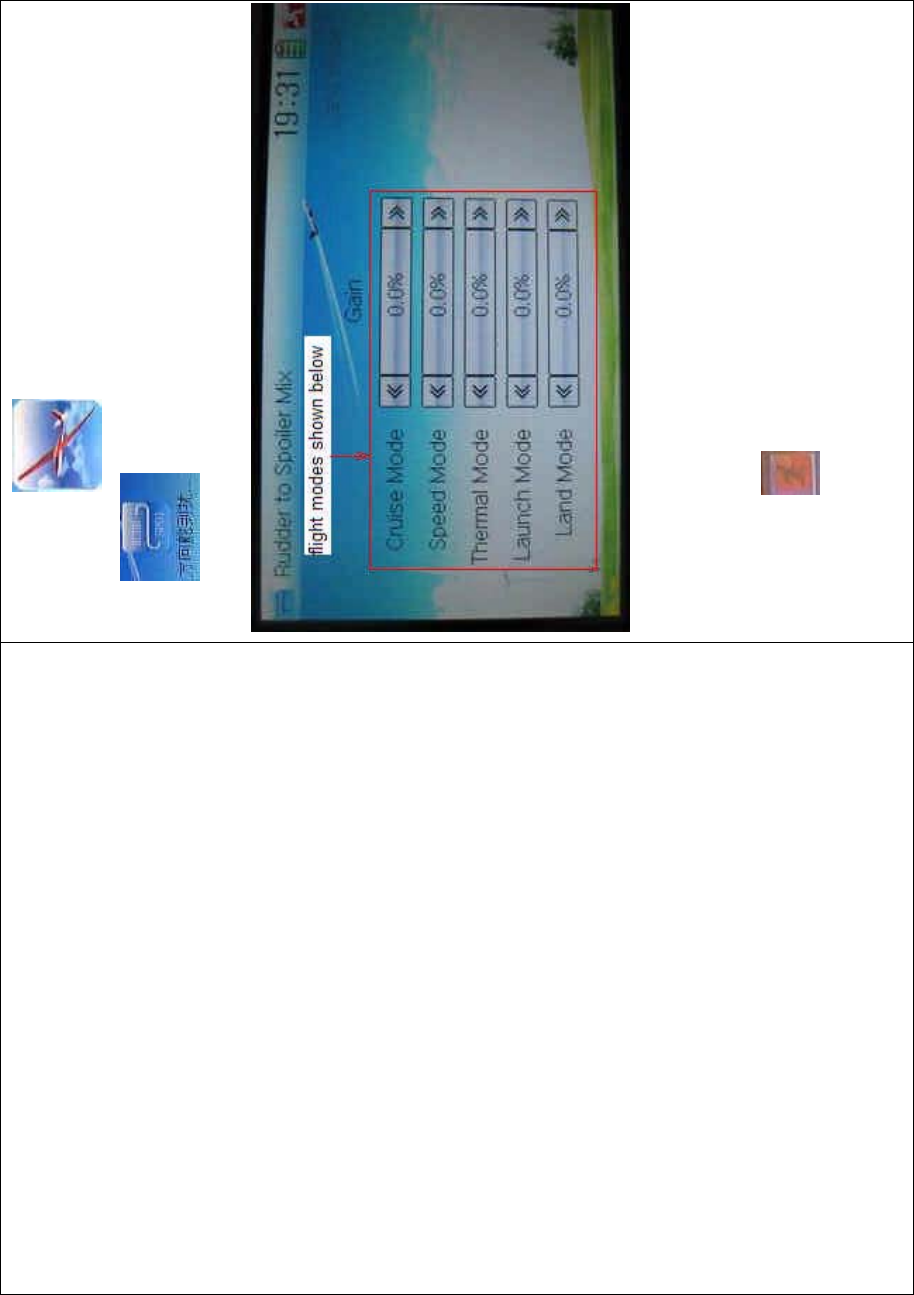
DEVO-8 Page no. Page 330 of 363
Touch the icon to enter Function Menu, and then click the
icon to enter the RUDDER TO SPOILER MIX
INTERFACE.
Touch the left or right navigation mark of the flight mode you desired to
decrease or increase, respectively, the gain with a range of 0.0 –
100.0%. The default setting is 0.0%.
Touch the icon to exit.
3.12 Aileron to rudder mix
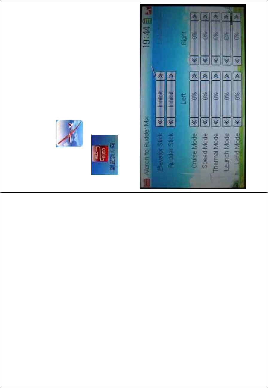
DEVO-8 Page no. Page 331 of 363
This function aims at mixing the rudder when operating the aileron. The
mix value can be respectively set in each flight mode. But the flight
mode should be previously set at Device Select in Model Menu (refer to
“2.10 Device Select”).
Setting method:
Touch the icon to enter Function Menu, and then click the
icon to enter the ALERON TO RUDDER MIX
INTERFACE.
1) Elevator stick setting

DEVO-8 Page no. Page 332 of 363
This function is that: if the elevator stick position is set at one point, this
point will become the cut-off point whether to mix. When the elevator
stick is moved down from this point, the mix will be cancelled; while the
elevator stick is moved up from this point, the mix will be activated.
Touch the left or right navigation mark of Elevator Stick to decrease or
increase, respectively, the value with a range of D1 – 100%. When the
elevator stick is moved down from the set value, the mix will be
cancelled; while the elevator stick up from this value, the mix will be
activated. The default setting is Inhibit.
2) Rudder stick setting
The setting is same as above. The adjustable range is L/R 1 – L/R
100%, and the factory setting is Inhibit.
3) Mix value setting for each flight mode
There are total five flight modes. The flight mode should be previously
set at Device Select in Mode Menu (refer to “2.10 Device Select”).
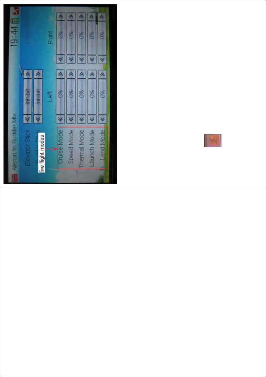
DEVO-8 Page no. Page 333 of 363
Touch the navigation mark of Left to change the leftward mix value of
aileron to rudder when moving the aileron stick leftward. It is possible to
alter the mix direction via changing the sign before the value. The
adjustable mix is ± 125%.
Touch the navigation mark of Right to change the rightward mix value of
aileron to rudder when moving the aileron stick rightward. It is possible
to alter the mix direction via changing the sign before the value. The
adjustable mix is ± 125%.
Click the icon to exit.
3.13 Elevator to flap mix
This function aims at mixing flap when operating elevator stick. It can be
respectively set in each flight mode, which should be previously set at
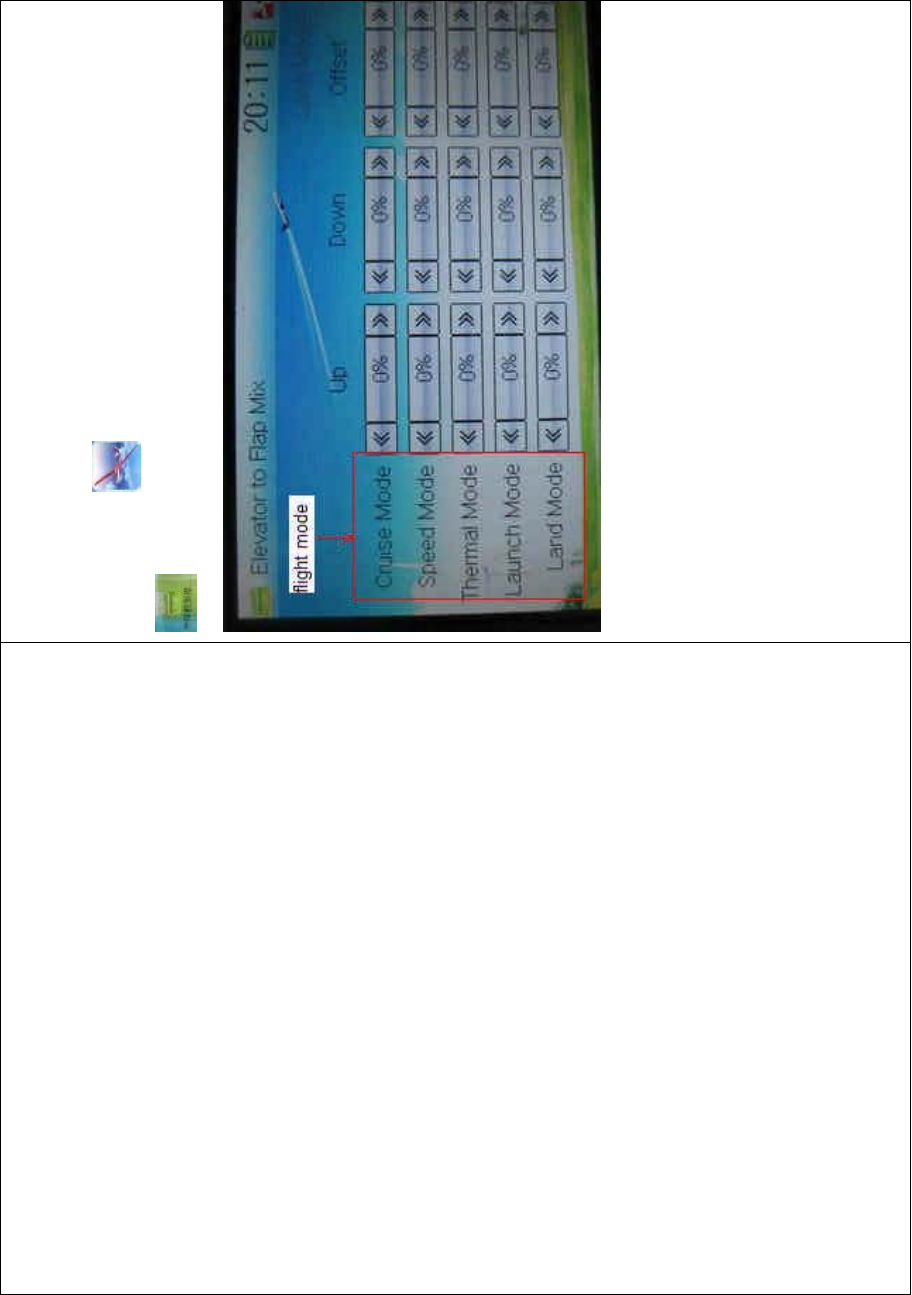
DEVO-8 Page no. Page 334 of 363
Device Select in Mode Menu (refer to “2.10 Device Select”).
Setting method:
To uc h t he i co n to enter Function Menu, and then click the icon
to enter the ELEVATOR TO FLAP MIX INTERFACE.
Touch the navigation mark of Up in the flight mode you desire to change
the mix value of elevator to flap when moving the elevator stick
upwards. It is possible to alter the mix direction via changing the sign
before the value. The adjustable mix value is ± 125%.
Touch the navigation mark of Down in the flight mode you desire to
change the mix value of elevator to flap when moving the elevator stick
downwards. It is possible to alter the mix direction via changing the sign
before the value. The adjustable mix value is ± 125%.
Touch the navigation mark of Offset, which is corresponding to the flight

DEVO-8 Page no. Page 335 of 363
mode, to amend the central point of flap servo. The bigger the value is,
the bigger the offset will be. It is possible to alter the offset direction via
changing the sign before the value. the adjustable offset range is ±
100%.
Click the icon to exit.
3.14 Aileron to flap mix
This function aims at mixing flap when operating aileron stick. It can be
respectively set in each flight mode. But the flight mode should be
previously set at Device Select in Mode Menu (refer to “2.10 Device
Select”), and the flap dual channels should also be previously activated
at Wing Type in Mode Menu (refer to “2.12 Wing Type”).
Setting method:
Touch the icon to enter Function Menu, and then click the
icon to enter the AILERON TO FLAP MIX
INTERFACE.
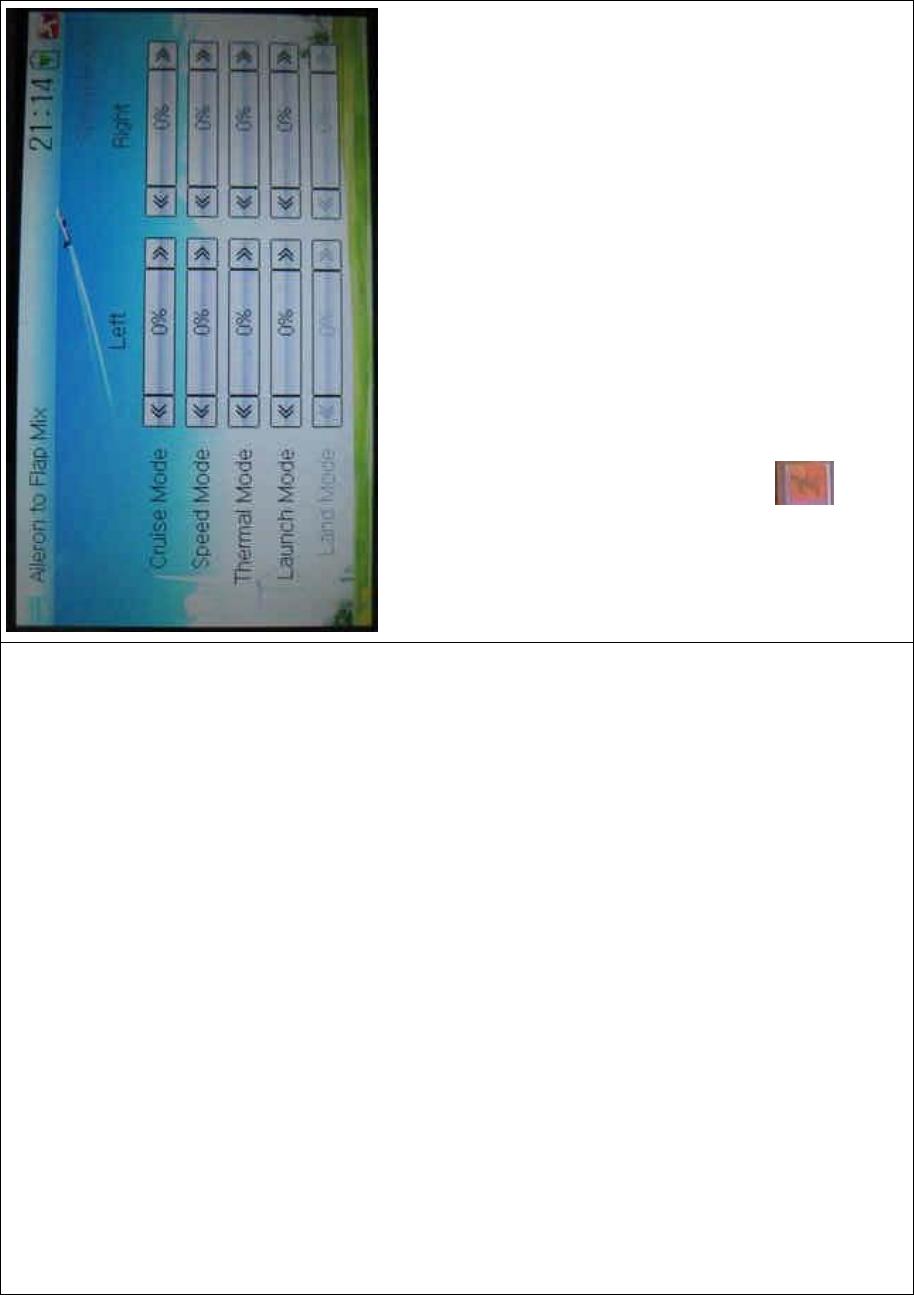
DEVO-8 Page no. Page 336 of 363
There are total five flight modes. The corresponding flight mode should
be previously set at Device Select in Mode Menu (refer to “2.10 Device
Select”).
Touch the navigation mark of Left in the flight mode you desire to
change the flap mix value when moving the aileron stick leftward. It is
possible to alter the mix direction via changing the sign before the
value. The adjustable mix value is ± 125%.
Touch the navigation mark of Right in the flight mode you desire to
change the flap mix value when moving the aileron stick rightward. It is
possible to alter the mix direction via changing the sign before the
value. The adjustable mix value is ± 125%.
Click the icon to exit.
3.15 Flap to tip-aileron mix
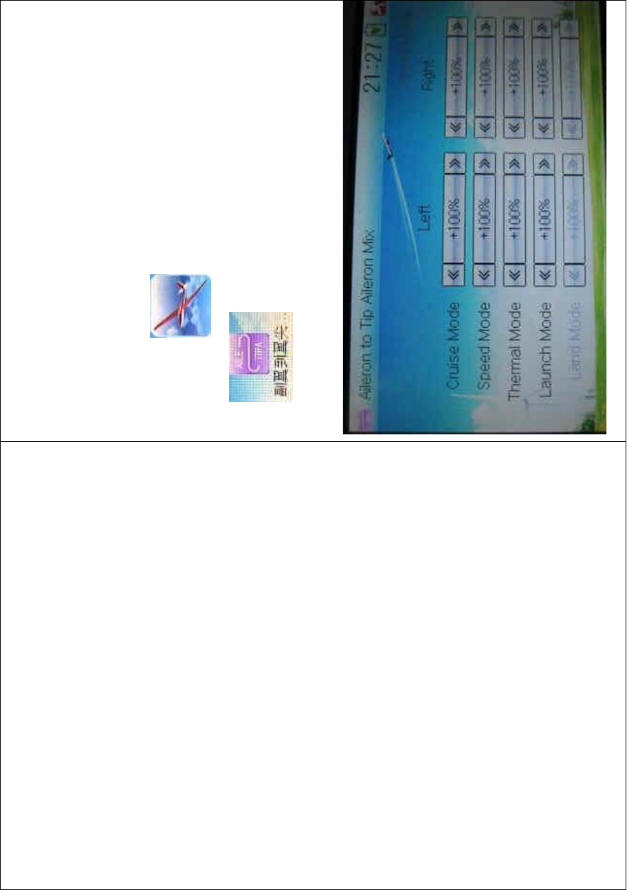
DEVO-8 Page no. Page 337 of 363
The function aims at mixing tip aileron when operating flap. It can be
respectively set in each flight mode. But the flight mode should be
previously set at Device Select in Mode Menu (refer to “2.10 Device
Select”), and the tip aileron should also be activated at Wing Type (refer
to “2.12 Wing Type”).
Setting method:
Touch the icon to enter Function Menu, and then click the
icon to enter the FLAP TO TIP AILERON MIX
INTERFACE.

DEVO-8 Page no. Page 338 of 363
There are total five flight modes. The corresponding flight mode should
be previously set at Device Select in Mode Menu (refer to “2.10 Device
Select”).
Touch the navigation mark of Left in the flight mode you desire to
change the tip flaperon mix value when moving the aileron stick
leftward. It is possible to alter the mix direction via changing the sign
before the value. The adjustable mix value is ± 125%. The default
setting is 100%.
Touch the navigation mark of Right in the flight mode you desire to
change the tip flaperon mix value when moving the aileron stick
rightward. It is possible to alter the mix direction via changing the sign
before the value. The adjustable mix value is ± 125%. The default
setting is 100%.
Click the icon to exit.
3.16 Flap rate
This function can set the flap rate in all the flight modes. 0% is set as
the neutral center of flap angle. It is possible to set the flap rate of either
upward or downward direction. There are total five flight modes, each
one of which should be previously set at Device Select in Model Menu
(refer to “2.10 Device Select”).
Setting method:
Touch the icon to enter Function Menu, and then click the
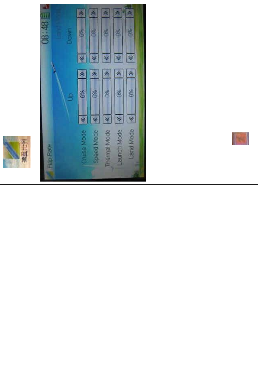
DEVO-8 Page no. Page 339 of 363
icon to enter the FLAP RATE INTERFACE.
Touch the navigation mark of Up to change the flap rate when flap
moving upward. It is possible to alter the direction by changing the sign
before the value. The adjustable range is 125%, and the default setting
is 0%.
Touch the navigation mark of Down to change the flap rate when flap
moving downward. It is possible to alter the direction by changing the
sign before the value. The adjustable range is 125%, and the default
setting is 0%.
Click the icon to exit.
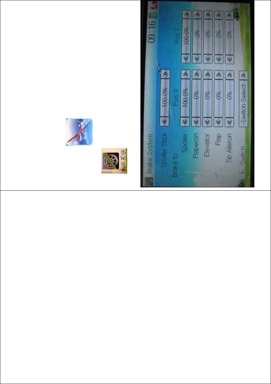
DEVO-8 Page no. Page 340 of 363
3.17 Brake system
Through the spoiler stick operation, all the actions caused by mobile
wings in main wings will be turned into the mix which aims at brake. It
canbeswitchedbetweenPos0andPos1viasettingtheitemSwitch.
Setting method:
Touch the icon to enter Function Menu, and then click the
icon to enter the BRAKE SYSTEM INTERFACE.
1) Spoiler stick setting

DEVO-8 Page no. Page 341 of 363
When the spoiler stick is set at one certain point, this point will become
the cut-off point whether to brake. The mixing will be working when the
spoiler stick is being moved to this point from down to up.
The spoiler stick position will be set through touching the navigation
mark of Spoiler to change the value. The adjustable range is
0.0-100.0% and the default value is 100.0%.
2) Mix value setting
Mix value setting for brake to the corresponding item is shown as
below:
2.1) Brake to Spoiler
ThebrakemixatPos0willbealteredthroughtouchingthenavigation
mark of Pos 0 at Spoiler to change the value. The adjustable value is
0.0-100%, and the default setting is 100.0%.
ThebrakemixatPos1willbealteredthroughtouchingthenavigation
mark of Pos 0 at Spoiler to change the value. The adjustable value is
0.0-100%, and the default setting is 100.0%.
2.2) Brake to Flaperon
The setting is same as above. It is possible to change the mix direction
via altering the sign before the value. The adjustable value is ± 125%,
and the default setting is 0%.
2.3) Brake to Elevator
The setting is same as above.
2.4) Brake to Flap
The setting is as above.
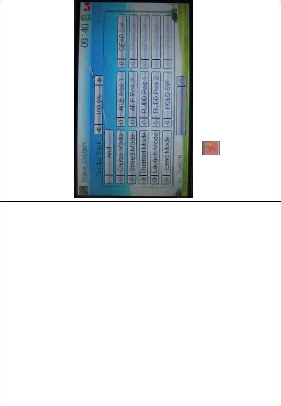
DEVO-8 Page no. Page 342 of 363
2.5) Brake to Tip aileron
The setting is same as above.
3) Switch setting
Touch the navigation mark of Switch and expand a selectable list shown
as below. Touch the desired switch item to make “0” turn into “1”. If two
or more switches are chosen, the item And should be selected.
Touch the icon to exit.
3.18 Program mix
There are total eight sets of Program Mix. It is possible to freely set the
channels and values which you want to mix.
Setting method:
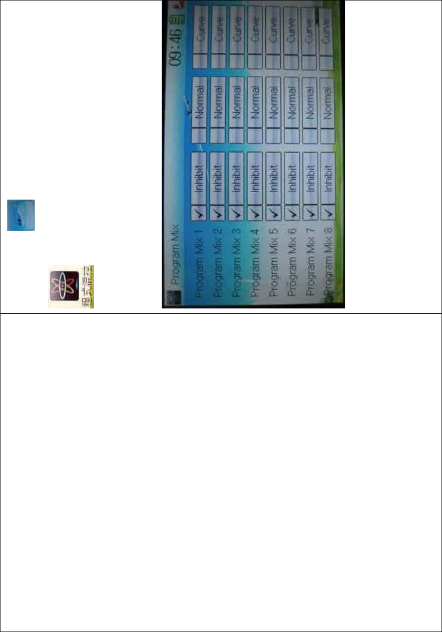
DEVO-8 Page no. Page 343 of 363
To uc h t he ico n to enter Function Menu, and then click
to enter the PROGRAM MIX INTERFACE.Eight
Program Mix names and their current statuses are shown (the factory
default setting is Inhibit). Take Program Mix 1 as an example to show
how to use.
.
A. Setting method for Normal in Program Mix 1
Touch the item Normal in Program Mix 1 and expands an INQUIRY
“All Servos Hold?” Click OK for all the servos will be locked at the
current statuses; click Cancel for unlocked. Enter the next interface
after clicking.
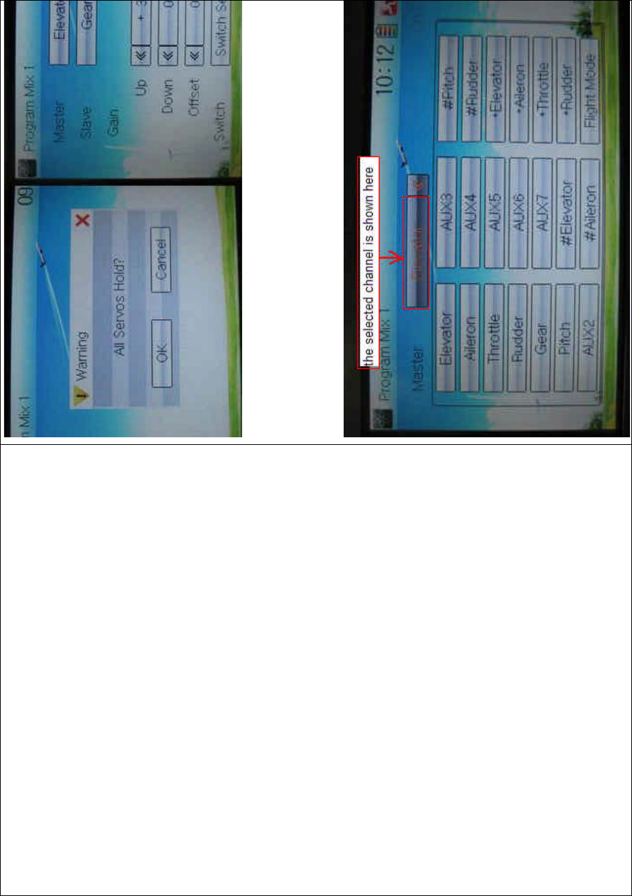
DEVO-8 Page no. Page 344 of 363
1) Mater channel setting
Touch the navigation mark of Master and expands a selectable
dropdown menu. After clicking the desired channel, its name will be
showninMaster.

DEVO-8 Page no. Page 345 of 363
2) Slave channel setting
Touch the navigation mark of Slave and expands a selectable
dropdown menu. Click the desired channel which will be shown in
Slave.
3) Gain setting
The item Gain includes Pos 0, Pos 1, and Offset. Take Elevator at
Master channel as an example.
3.1) Pos 0:
Mix amount setting when elevator stick moved upward: touch left or
right navigation mark of Up to decrease or increase, separately, the mix
amount. It is possible to reverse mix direction thro ugh c hanging the plus
or minus sign before amount. The adjustable range is ±125%.

DEVO-8 Page no. Page 346 of 363
Mix amount setting when elevator stick moved downward: touch left or
right navigation mark of Down to decrease or increase, separately, the
mix amount. It is possible to reverse mix direction through changing the
plus or minus sign before amount. The adjustable range is ±125%.
3.2) Pos 1
The setting is same as above.
3.3) Offset setting
If the elevator stick position is set at one certain point, this point will
become the cut-off point whether to offset. The offset will be cancelled
when the elevator stick is moved downward from this point, and
activated when the elevator stick moved upward from this point.
Touch the left or right navigation mark of Offset to adjust the value,
which is the cut-off point whether to offset. The offset to Slave channel
will be cancelled if the elevator stick is moved down from this point, and
activated if the elevator stick moved up from this point. It is possible to
reverse the offset direction by changing the sign of plus or minus before
the value. the adjustable range is ±100%, and the factory setting is
0%.
4) Switch selection
Touch the right navigation mark of Switch and pop up a dropdown menu
which contains the adjustable items. Click the desired switch. Then
touch the right navigation mark to return the previous interface. If more
than two items are selected, the time And should be chosen.
Click the icon to return to the interface of Program Mix for other
setting, or click the icon once again to exit.
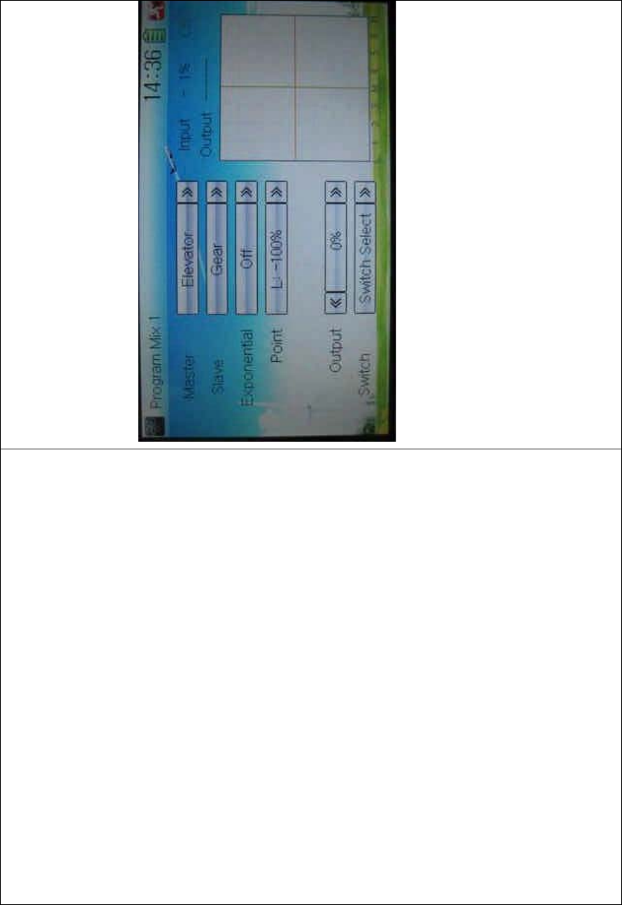
DEVO-8 Page no. Page 347 of 363
B. Setting method for Curve in Program Mix2
Touch the item Curve in Program Mix 1 and expands an enquiry “All
Servos Hold?” Click OK for all the servos will be locked at the current
statuses; click Cancel for unlocked. Enter the next interface after
clicking.
1) Master channel setting
Touch the navigation mark of Master and expand a selectable
dropdown menu. Select the desired channel and its name will be shown
in Master. Click the navigation mark of Master to return to the
PROGRAM MIX 1 INTERFACE.
2) Slave channel setting
Touch the navigation mark of Slave and expand a selectable dropdown
menu. Select the desired channel and its name will be shown in Slave.
Click the navigation mark of Slave again to return to the PROGRAM
MIX 1 INTERFACE.

DEVO-8 Page no. Page 348 of 363
3) Position
Touch the navigatio n mark of Position and expand a list with Pos 0 and
Pos 1. select the desired position.
4) Exponential
Touch the navigation mark of Exponential and expand a dropdown
menu with two options of Off and On. The pitch curve will be smoothly
changed if On chosen, and changed in the form of fold line if Off
chosen.
5) Point
Touch the navigation mark of Point and expand a dropdown menu with
nine points. Click the point you want to set, and then touc h the
navigation mark to return.
6) Status
Touch the navigation mark of Status and expand a dropdown with two
options of Inhibit and Active. Touch Inhibit for unchangi ng t he current
amount (the default setti ng is Inhi bit); click Active for changi ng the
amount, and a popup of Output will be followed below.
7) Output
Touch the left or right navigation mark of Output to decrease or
increase, respectively, the output amount with a range of ±100.0%. It is
possible to reverse the mix direction by changing the plus or minus sign
before the amount.
8) Switch
Touch the navigation mark of Switch and expand a usable dropdown
menu. Select the desired switch, and then click the navigation mark to
return. If more than two items are selected, the item And should be
chosen.

DEVO-8 Page no. Page 349 of 363
Click the icon to return to the PROGRAM MIX
INTERFACE for other setting, or click the icon once again to
exit.
3.19 Monitor
This function can display the current statuses and positions of all the
channels’ outputs, and check the current working status of each
channel.
Touch the icon to enter Function Menu, and then click the
icon to enter the MONITOR INTERFACE for checking the
current working status of each channel.
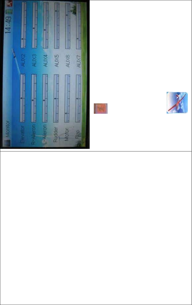
DEVO-8 Page no. Page 350 of 363
Click to the icon exit after finished.
3.20 Fail safe
There are two possibilities for use if the transmission signal is under
abnormal condition. The first one is to lock the last action data received;
the second one is to execute the pre-set data which is pre-set. The
default setting is Servo Hold.
Setting method:
Touch the icon to enter Function Menu, and then click
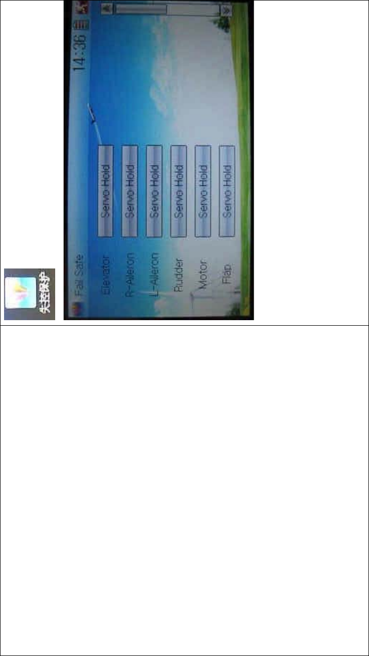
DEVO-8 Page no. Page 351 of 363
to enter the FAIL SAFE INTERFACE.
Take the item Elevator as an example to explain.
1) Elevator setting:
Touch the item Elevator (it is unnecessary to set if Elevator is at Servo
Hold) and expand a sub-item in its right. Click the left or right navigation
mark to decrease or increase, respectively, the position amount which
centers on the neutral point of servo. The settable range is 125%, and
0% is the servo’s neutral position.
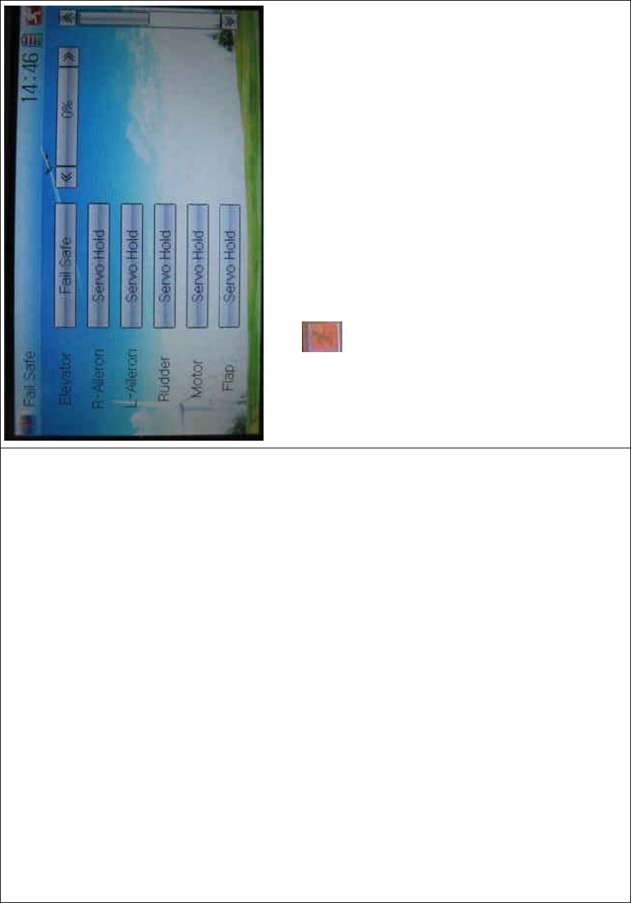
DEVO-8 Page no. Page 352 of 363
2) The setting methods for other channels are same as above.
Click the icon to exit after finished.
Note: checking whether all the actions when fail safe happened are
correct is a must after the setting is finished. It is dangerous to use full
throttle, especially after fail safe taken place.
3.21 Trainer
ThetrainingfunctioncanbepracticedviatwoDEVO-8equipments.
Setting method:
A. Data copy
Using the wireless copy function of the two DEVO-8 transmitters, the
model data saved in the trainer’s transmitter can be transmitted to the
trainee’s to ensure the model parameters are exactly same. Regarding
the copying method, refer to “2.4 Model Wireless Copy”
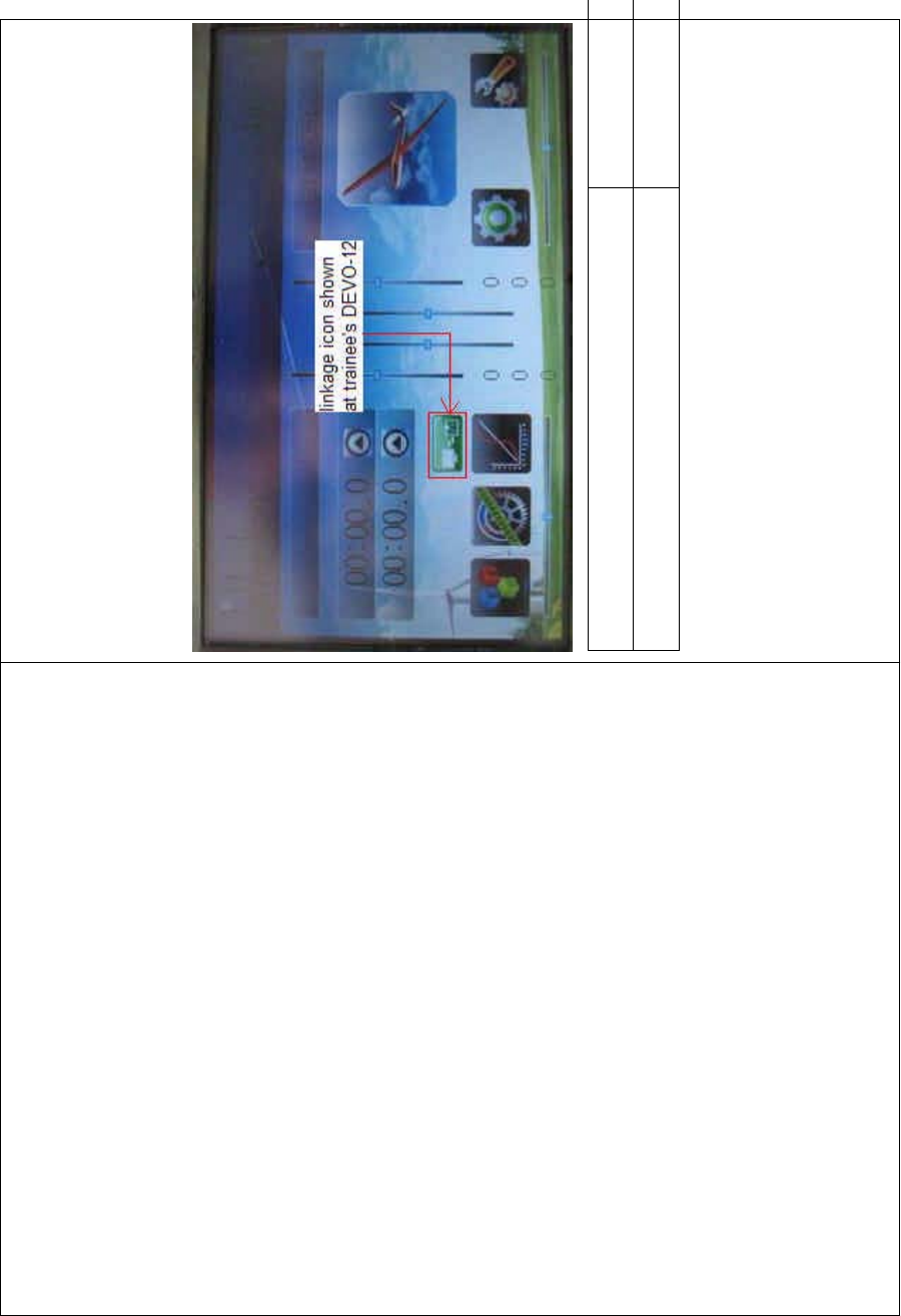
DEVO-8 Page no. Page 353 of 363
B. Linkage
Insert one end of the signal wire into DSC socket at the rear face of the
trainee’s DEVO-8, and then turn on the power. A linkage icon will be
shown on the boot screen. Find out the trainee’s model data.
English Your language
Linkage icon shown at trainee’s icon
Turnonthepowerofthetrainer’sDEVO-8.Findoutthetrainee’smodel
data, and let the trainer’s DEVO-8 fly the aircraft model normally. Then
turn off the power.
Insert the other end of the digital signal wire into the trainer’s DEVO-8,
and then turn on its power. A linkage icon will be shown as below:
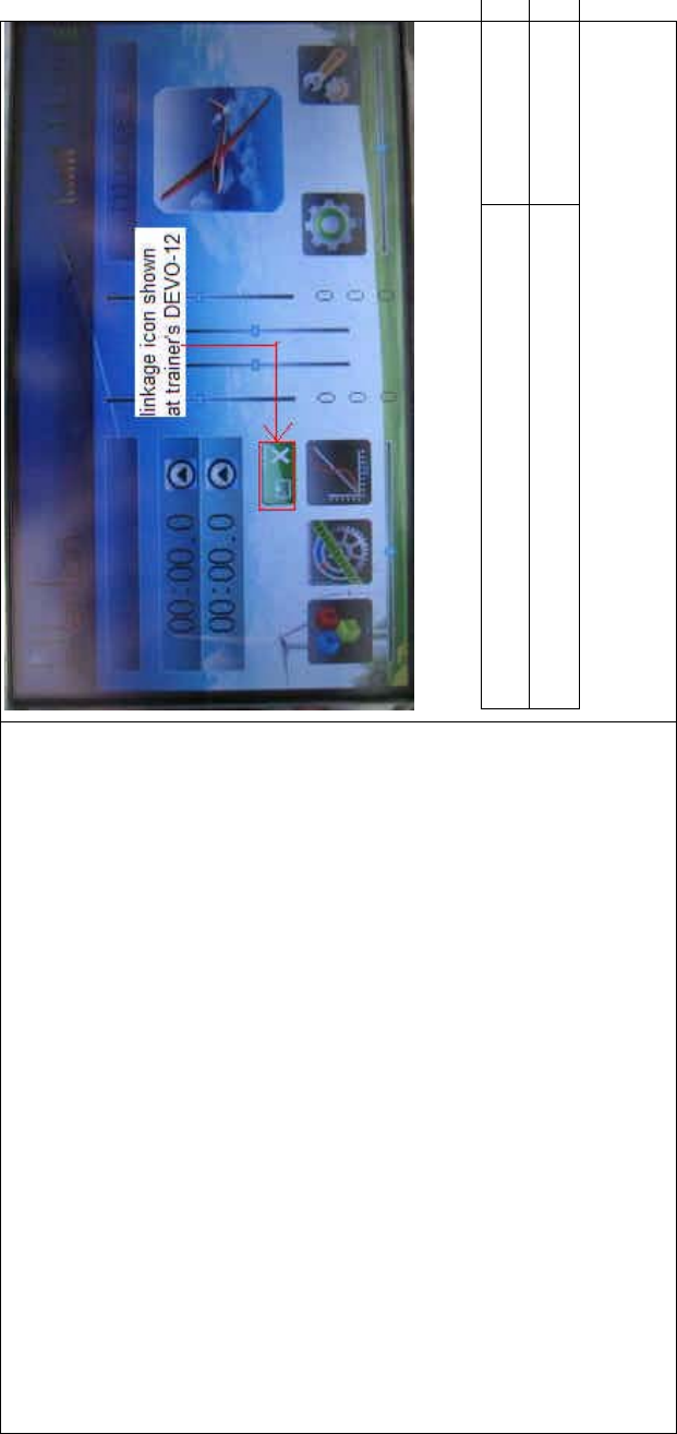
DEVO-8 Page no. Page 354 of 363
English Your language
Linkage icon shown at trainer’s DEVO-8

DEVO-8 Page no. Page 355 of 363
English Your language
DSC socket
Two ends of digital signal wire
Training status display: when the trainer’s icon becomes into “X”, the
trai nee stops flying and t he trainer is worki ng; when the trai ner’s icon
turns into ĀĜ”, the trainee is flying and the trainer is in leisure.

DEVO-8 Page no. Page 356 of 363
English Your language
Trainee is off and trainer is working
Trainee is worki ng and trainer is off
C) Usage method
The traini ng switch should be worked with the TRN traini ng lever at the
right top of DEVO-8.

DEVO-8 Page no. Page 357 of 363
English Your language
TRN: traini ng lever
If the TRAINER (fingerREMOVESXOOVWKHWUDLQLQJOHYHU751D³¥´LV
shown in the linkage icon; if the trainer releases his finger from the
trainer lever, an “X” will be shown there.
Setting for traini ng f unction c hannels
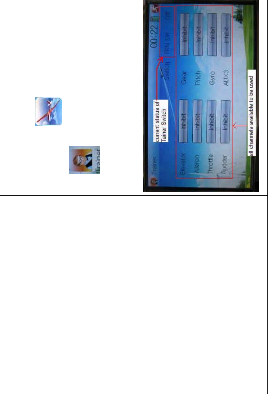
DEVO-8 Page no. Page 358 of 363
Trainee is available to get full or part of flight control power to the
aircraft model via setting the training function channel in the trainer’s
DEVO-8. Below is the setting method:
Touch the s hortcut icon to enter Function Menu, and then
touch in Function Menu access to Trainer screen. The
available channels are shown below, and the current status of trainer
switch TRN is also shown.
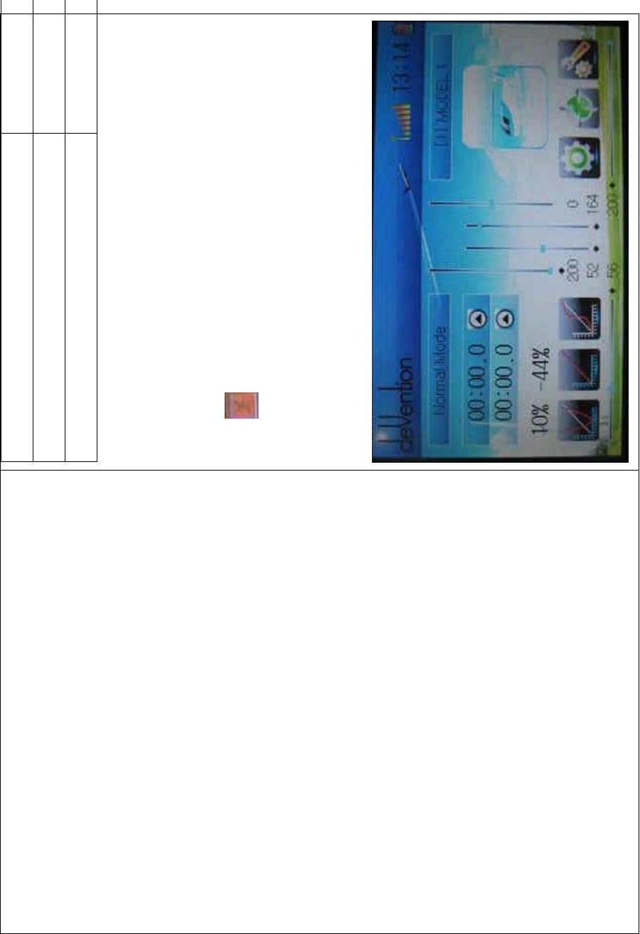
DEVO-8 Page no. Page 359 of 363
English Your language
Current status of Trainer Switch (TRN SW)
All channels available to be used
Touch the channel(s) which you desire to grant to trainee. The
channel(s) you have touched will be activated as “Active”. The channels
which are not granted to trainee keep inhibited. The default setting is
“Inhibit”.
To uc h to save and exit after finished.
3.22 Timer
There are two timers which can be set as stopwatch and countdown,
respectively. Each timer can be operated by switch or by shortcut.
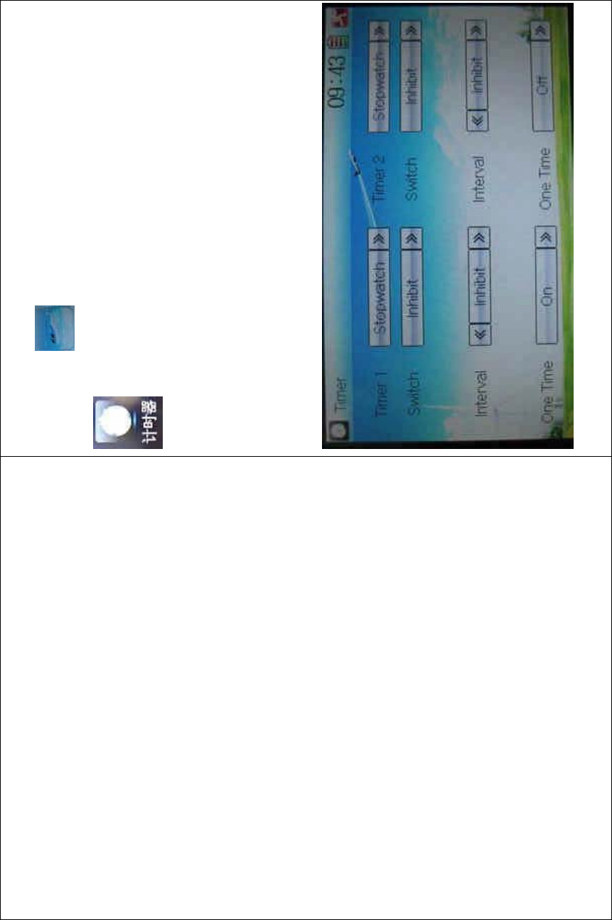
DEVO-8 Page no. Page 360 of 363
Setting method:
Touch the icon to enter Function Menu, and then click the icon
to enter the TIMER INTERFACE.
A. Setting for Timer 1
7) Timer 1 setting
Touch the navigation mark of Timer 1 and expand a dropdown of
Stopwatch and Countdown. Select the desired timing method. The
timing range of stopwatch is from 0 to 59:59 (59 minutes 59 seconds).
Stopwatch view:
Countdown view:
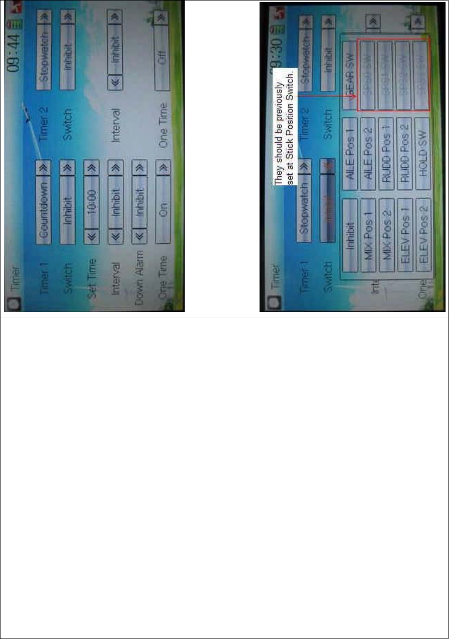
DEVO-8 Page no. Page 361 of 363
Take countdown manner as an example to explain.
8) Switch selection
Touch the navigation mark of Switch and get a selectable dropdown

DEVO-8 Page no. Page 362 of 363
We can select the desired item but these items of SPS0 SW, SPS1 SW,
SPS2, and SPS3 which should be previously set at Stick Position
Switch at Model Menu (refer to “2.8 Stick Position Switch”).
9) Set time
The settable countdown time range is from 00:05 to 59:55.
10) Interval
This item offers the possibility to set the warning interval. It will warn
once every interval time. The adjustable range is from 00.05 to 05:00.
The default setting is Inhibit.
11) Down alarm
It is possible to set the down alarm in countdown. The setting range is
from 00:01 to 03:00. The default setting is Inhibit.
12) One time
If this function is turned on, counting down cannot be stopped once the
countdown works. The default setting is Off.
B. Setting for Timer 2 is same as that for timer 1.
Touch the icon to exit after finished.
᷵䯙㗙˖
Proofread by Mr. Manuel Campos