Guangzhou Chiyuan Electronic 300L 3CH Radio Control User Manual
Guangzhou Chiyuan Electronic Co.,Ltd 3CH Radio Control Users Manual
User Manual

Thank you for purchasing our R/C system.
Before using, read this manual carefully.
3-Ch 2.4G Radio Control System
Introduction Manual
DIGITAL PROPORTIONAL RC SYSTEM 2.4G FHSS TECHNOLOGY
DIGITAL PROPORTIONAL R/C SYSTEM
Y310/CY3S/CY320/N-4Q/8181C

R/C Introduction Manual
Table of Contents
Caution
1.1 Transmitter Chart
1.2
2.1
enu introduction
6
2 7
2 8 ST CURV
2 9 TH CURV
2 10 ABS
2 11 MODEL
2 12 SPEED
2 13
2 14
2 15 MIX
2 16 TH HOLD
2 17 F/S
2 18 NEUTRAL
2 SOUND
2
2 1
2 2 T
2.4G BINDING
Characteristics of system
2. 2 M
2. 3 Main-Menu Function
2. 4 EPA
2. 5 D/R
2. S_TRIM
. REV
.
.
.
.
.
. ATS
. BR_MIX
.
.
.
.
.19
.20 RESET
.2 M_RES
.2 IMER
3.1 Trim ADJ.
3.2 Handling Procedure For Batteries
3.3 Connection between Receiver and Servos
Technology Data
1
2
3
4
5
7
7
8
8
9
9
10
12
13
14
16
17
17
18
19
19
20
20
20
21
22
23
24
24
R/C Introduction Manual
R/C Introduction Manual 2
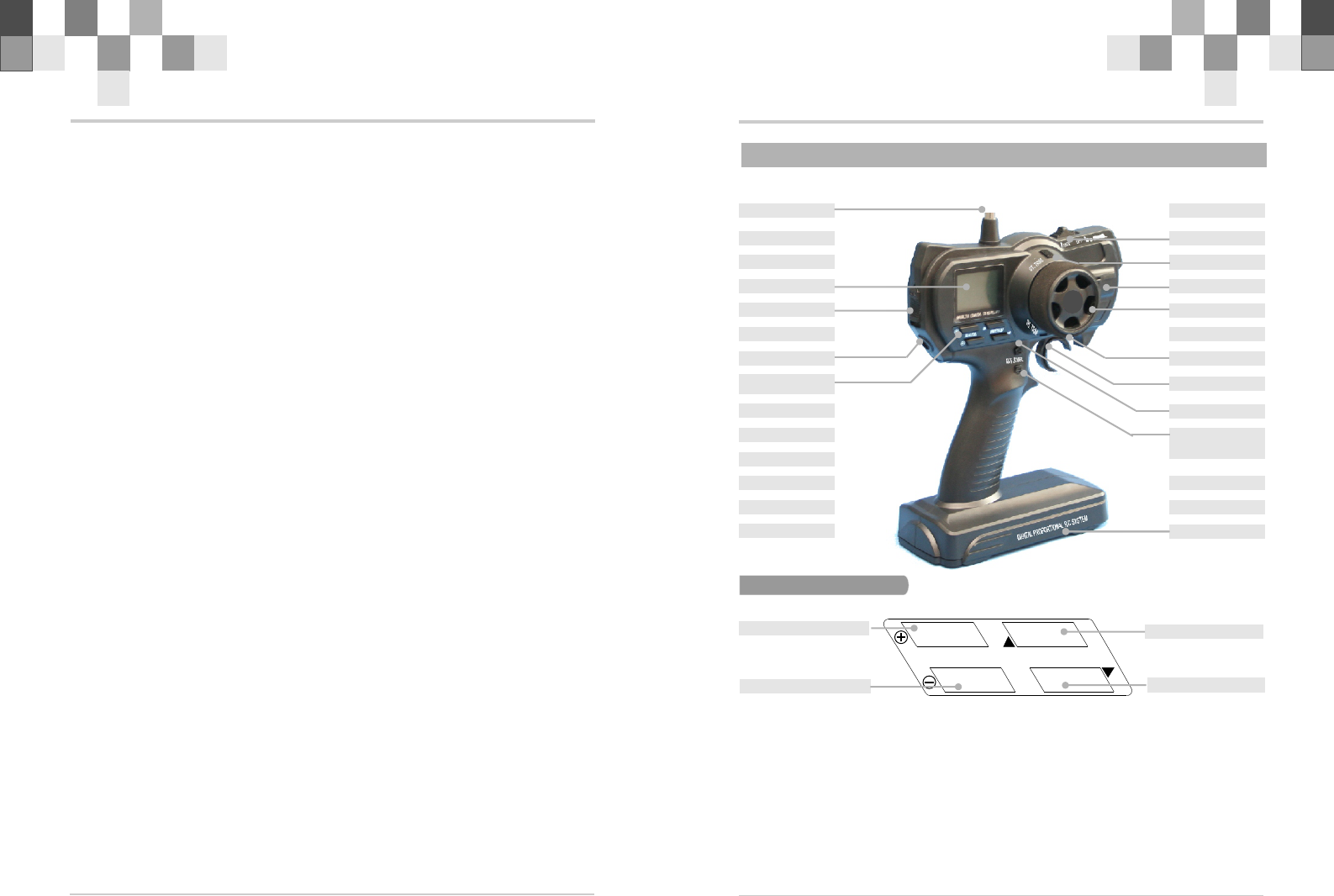
1.1 Transmitter Chart
Steering Wheel
Throttle Trim
Steering Trim
Throttle Trigger
电池仓
Edit Buttons
AUX Channel
Steering
Dual Rate
Edit Buttons
EXIT
ENTER
MODE&DATA
EXIT
ENTER
Battery Box
MODE&DATA +
MODE&DATA –
Antenna
LCD
Throttle Hold
Power Switch
Charging Jack
R/C Introduction Manual
1
Caution
!To work your R/C with your models correctly and safely, read this manual carefully and
keep it in a safe way as a reference introduction in the future.
!Warning:
1. This product is only equipped for radio controlled models;
2. The usage of this product should be approved by local relevant law or regulations;
3. We will not be responsible for the damages caused by unauthorized modification,
adjustment or replacement of parts of this product;
4. The manual may be altered without prior notice. Please contact us if you have any
corrections or clarifications that should be made in the manual.
!Please pay more attention to the parts in this manual, which are marked with “Warning”.
!Because of disturbance, do not work your radio control system simultaneously with others
at the same frequency.
!Before starting the transmitter, make sure the transmitter batteries are well loaded .The
voltage of transmitter batteries is never lower than 8.6V. And please check and confirm that
the servos are all well and properly connected.
!Please check and have a test on control surfaces to confirm the transmitter handling of each
part prior to each takeoff. The frequencies of the module and the receiver should be the
same.
!Keep the radio system away from moist, high temperature and strong shake. Do not clean
the product with solvent.
!The antenna does not touch anything else when power switch is turned on. Do not leave this
product and its accessories within the reach of small children.
!Please use this product according to your local relevant law or regulation, we are not
responsible for any incidents or damages.
4
3
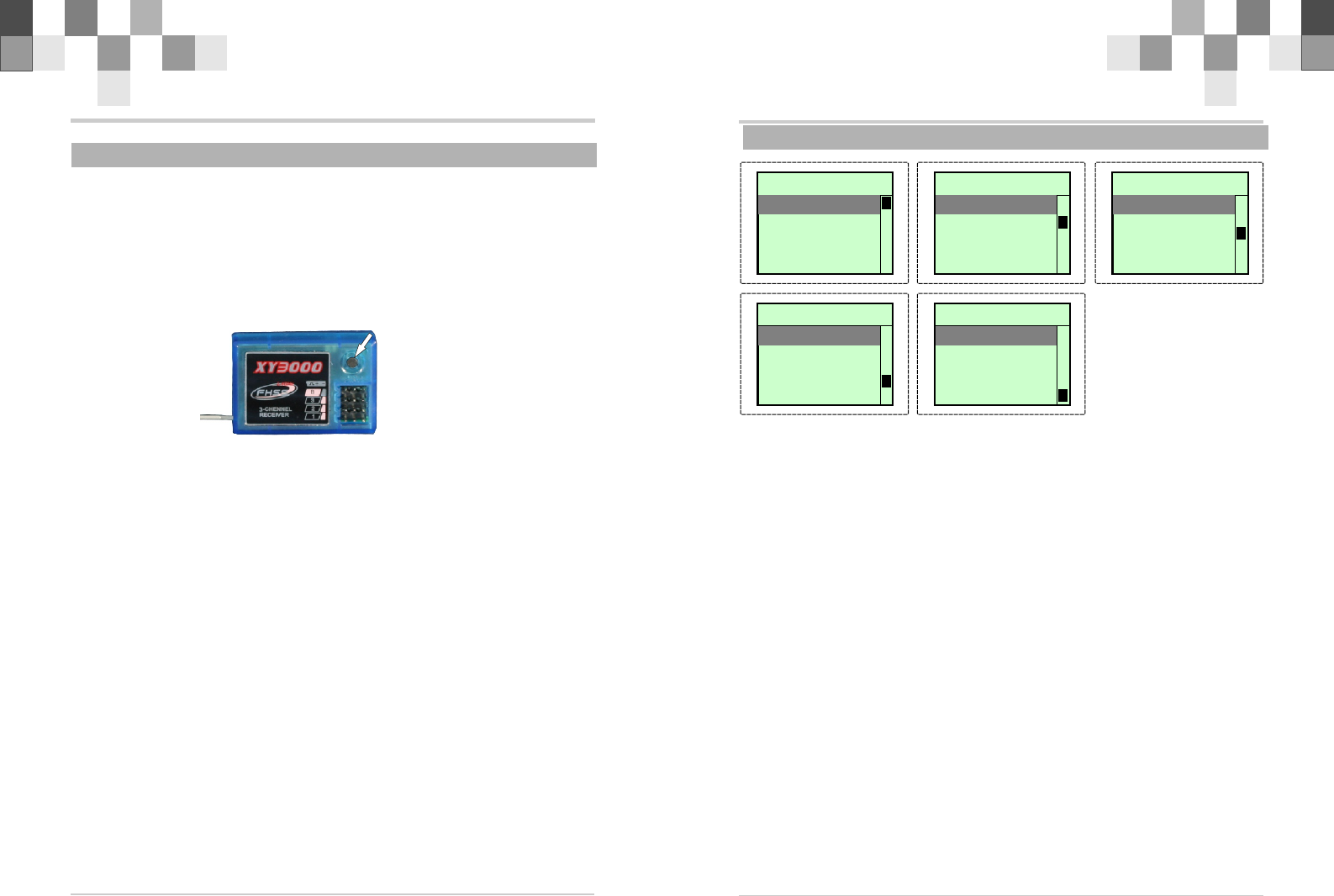
1.2 2.4G BINDING
R/C Introduction Manual
R/C Introduction Manual
BINDBIND
1. The Binding processing
Turn on the transmitter, then connect the power of receiver keeping the receiver "BIND"
button till the light turn on GREEN which means the binding is successful. After that, it's
unnecessary to bind again.
Caution: making sure that the RX and TX within one meter, and around 10 meters no
similar device.
If the light flashing, showing the binding failure, please do again as above indication.
2.1 Characteristics of system
F u n c t i o n 1 0 . 2 V F u n c t i o n 1 0 . 2 V
1:EPA
2:D/R
3:S_TRIM
4 : R E V
--3 channels End Point Adjustment
--Support dual rate function for the STEERING
--Sub-trim for THROTTLE channel and STEERING channel
--Model names can use up to 5 letters and numbers, so that easily understood names
can be set. A model memory with different fine setups can be created by using the model
copy function. Sixteen models can be added .
--Brake mixing for large cars (BRAKE)
Brake mixing of the front and rear wheels of 1/5GP and other large cars can be adjusted
independently.
--Anti-skid braking system (A.B.S)
This function applies the brakes so that the tires of gasoline engine cars, etc. do not
lose their grip on the road even when braking at corners.
--SPEED
TH-SPEED:Sudden trigger operation on a slippery road surface will only cause the
tires to spin and the model to not accelerate smoothly. By setting the throttle speed
function, operation can be performed smoothly and easily. It also suppresses battery
consumption.
ST-SPEED:
When you sense that the steering servo is too fast, etc., the servo operating speed
(direction that suppresses the maximum speed) can be adjusted.
--Auto-Start function (ATS):
A pre-set throttle position, less than full throttle, to be used for the initial acceleration off
the line without having wheel spin. When the trigger is released, auto-start is turned off
and throttle operates normally again.
--Racing timer (TIMER)
The N-4Q has two timers:Down_Timer and UP_Timer.
--Digital trim function
The current trim position is displayed on the LCD screen.
F u n c t i o n 1 0 . 2 V F u n c t i o n 1 0 . 2 V
5 : S T C U R V
6 : T H C U R V
7:ABS
8 : M O D E L
F u n c t i o n 1 0 . 2 V F u n c t i o n 1 0 . 2 V
1 3 : M I X
1 4 : T H H O L D
1 5 : F / S
16:NEUTRAL
F u n c t i o n 1 0 . 2 V F u n c t i o n 1 0 . 2 V
17:SOUND
18:RESET
19:M_RES
2 0 : T I M E R
F u n c t i o n 1 0 . 2 V F u n c t i o n 1 0 . 2 V
9 : S P E E D
1 0 : A T S
1 1 : M O D U L A T E
1 2 : B R _ M I X
R/C Introduction Manual 6
R/C Introduction Manual
5
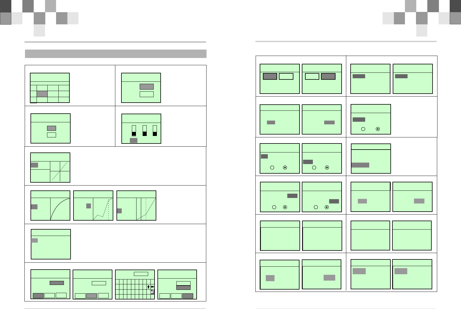
2.2 Menu introduction
E P A 1 0 . 2 V E P A 1 0 . 2 V
S T T H A U X
1 20%100 %1 0 0 %
F
B
100%120%100%
S T D / R 1 0 . 2 V S T D / R 1 0 . 2 V
POS0:
POS1: 100%
70%
S _TRIM 10 . 2 V S _TRIM 10 . 2 V
S T :
T H : 0
0
R EVERSE 1 0 . 2 V R EVERSE 1 0 . 2 V
TH AUX S T
REV
NOR
S T _ E X P 1 0 . 2 V
M : E X P
R : 0 %
STEERIN G STEERIN G
M:0 %
H:100%
T H _ C U R V 1 0 . 2 V
M : E X P
4 3 R :
B R : 0
STEERIN G STEERIN G
M:0 %
H:100%
T H _ C U R V 1 0 . 2 V
M : C U R
1 2
R : 8 8
3
B R : 0
STEERIN G STEERIN G
M:0 %
H:100%
TH_CURV 10.2V
M : V R T
P : 5 0
: 2 5R
B R : 0
A BS 10.2V
W D : 5 0
D L : 0
D T : 1
P T : 1 0 %
C Y : 15%
S M : 0
M O D E : I N H
M O D E L 1 0 . 2 VM O D E L 1 0 . 2 V
E D T C P Y SEL
MDL.N :
Mo d0 1
M O D E L 1 0 . 2 VM O D E L 1 0 . 2 V
E D T C P Y SEL
MDL.N :
Mo d0 1
MOL.N: A
S T UVWXYZ
J K LMNOP Q R
0 1 2 3 4 5 6 7 8 9
AB C DE F GH I
M D L . N :
A D A M |
R S T U V W X Y Z
I J K L M N O P Q
0 1 2 3 4 5 6 7 8 9
A B C D E F G H
M O D E L 1 0 . 2 VM O D E L 1 0 . 2 V
MDL.N :
Mo d0 0
S E L C P Y E D T
M O D E L 1 0 . 2 VM O D E L 1 0 . 2 V
MDL.N :
Mo d0 0
S E L E D T C P Y
C P Y T O
Mo d0 1
EPA(Page8) D/R(Page9)
S_TRIM(Page9) REV(Page10)
ST CURV(Page10)
TH CURV(Page11)
ABS(Page13)
MODEL(Page14)
M I X 1 0 . 2 V M I X 1 0 . 2 V
: L 5 0 R 5 0
T H : L 5 0 R 5 0
E N : O N O F F
S T
S P E E D 1 0 . 2 V S P E E D 1 0 . 2 V
S T
T H
S P D . F L : 0 %
S P D . B K : 0 %
S P E E D 1 0 . 2 V S P E E D 1 0 . 2 V
S T
T H
S P D . F L : 0 %
A T S 1 0 . 2 V A T S 1 0 . 2 V
T R I : 1 %
P O S : 0 %
D L Y : 0
M O D : I N H
A T S 1 0 . 2 V A T S 1 0 . 2 V
TRI: 1 %
P O S : 0 %
D L Y : 0
M O D : A C T
MOD
RST
M O D U L A T E 1 0 . 2 V
S E T R F C O M
[ ] [ Y E S ]N O
MOD
RST
M O D U L A T E 1 0 . 2 V
S E T R F C O M
[ N O ] [ ]Y E S
S E T O K .
B K - M I X 1 0 . 2 V
: 8 0 %
E N : O N O F F
R A T E
M I X 1 0 . 2 V M I X 1 0 . 2 V
T H : L 5 0 R 5 0
: L 6 0 R 5 0
E N : O N O F F
AUX
F / S 1 0 . 2 V
S T : 0 %
T H : 0 % I N H
E N : O N O F F
A C T
F / S 1 0 . 2 V
S T : 0 % A C T
T H : 2 0 %
E N : O N O F F
INH
T H H O L D 1 0 . 2 V
VALUE: 0 %
T H . H O L D :
N e u t r a l 1 0 . 2 V
N O Y E S
R E A D Y
Set Neutral?
N e u t r a l 1 0 . 2 V
N O
O K
YES
Set Neutral?
S O U N D 1 0 . 2 V
S O U N D : I N H
S O U N D 1 0 . 2 V
S O U N D : A C T
S YSTEM
R ESE T ING . . .
S YSTEM
R ese t S yst e m ?
M _ R E S 1 0 . 2 V
R e s e t D A T A ?
N O Y E S
R E A D Y
M _ R E S 1 0 . 2 V
R e s e t D A T A ?
N O
O K
Y E S
T I M E R 1 0 . 2 V
T : 0 m 0 s
MODE: I N H
T I M E R 1 0 . 2 V
T : 3 m 2 s
MODE:DN_T
ATS(Page17)
BK_MIX(Page19)
TH HOLD(Page20)
NEUTRAL(Page21)
SYSTEM(Page22)
TIMER(Page23)
SPEED(Page15)
MODULATE(Page18)
MIX(Page19)
F/S(Page21)
SOUND(Page22)
M_RES(Page22)
R/C Introduction Manual 8
R/C Introduction Manual
7
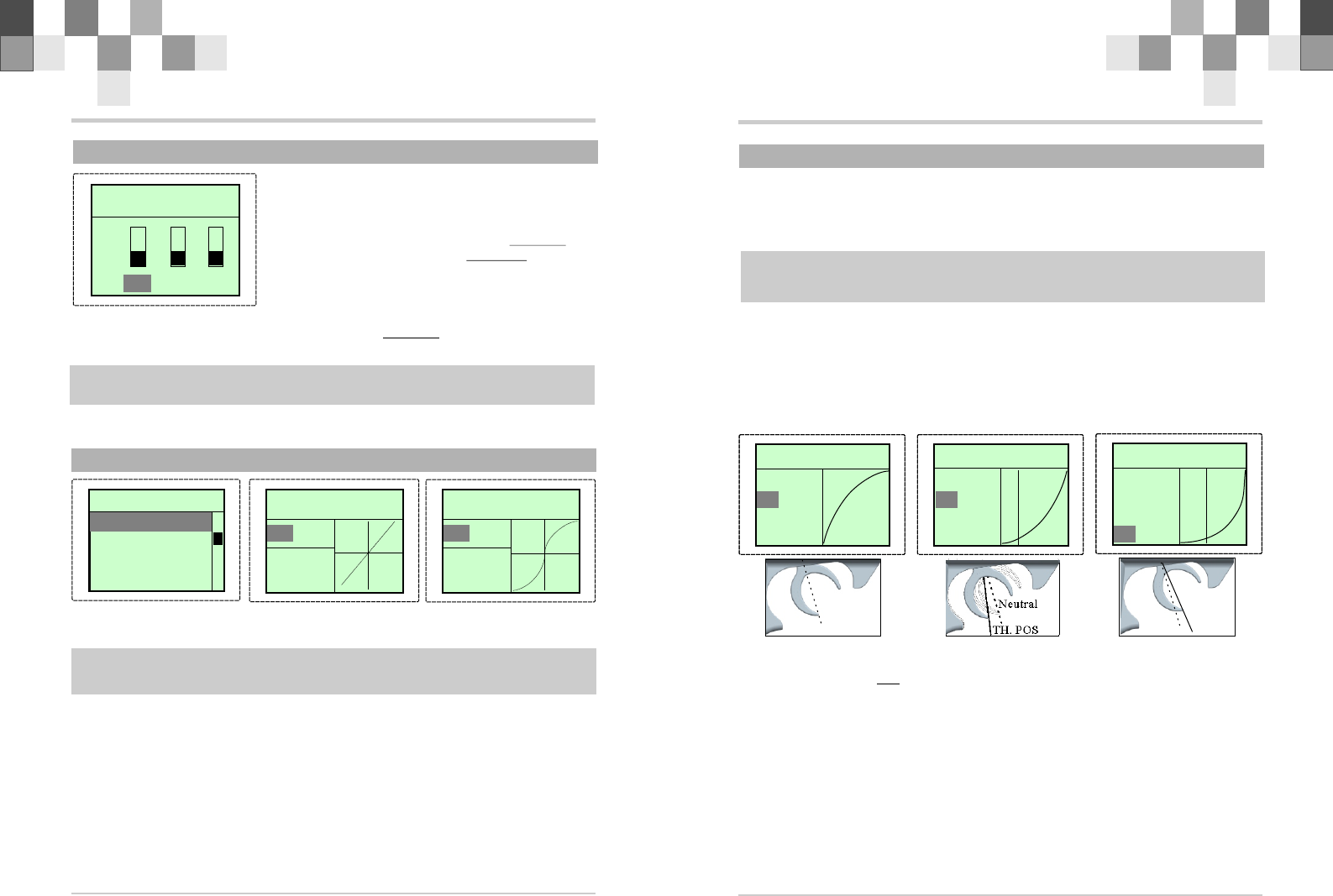
E P A 1 0 . 2 V E P A 1 0 . 2 V
S T T H A U X
120%100%1 0 0 %
2.4 EPA
F
B
!Use this when performing left and right steering
angle adjustments, throttle high side/brake side
operation amount adjustment, and channel 3 servo
up side/down side operation amount adjustment
during linkage.
!EPA adjusting value range: 0~120 %, default is
100%
1.Press “ENTER” in the power on interface and
enter function menu. Press “+” or “-” to
choose “EPA”. And press “ENTER” and enter
EPA adjusting interface.
2.Press “ENTER” to choose each adjusting item,
and then press “+” to increase and “-” to
decrease the value of the corresponding item.
3.Press “EXIT” to save your setting and leave EPA
interface, and back to the function menu interface.
TERMS:
F-FORWARD,B-BACK,ST-STEERIN,
TH-THROTTLE,AUX-AUXILLIARY
SERVO
050%
100%
120%
50%
100%
120%
RIGHT
FWD
LEFT
BACK
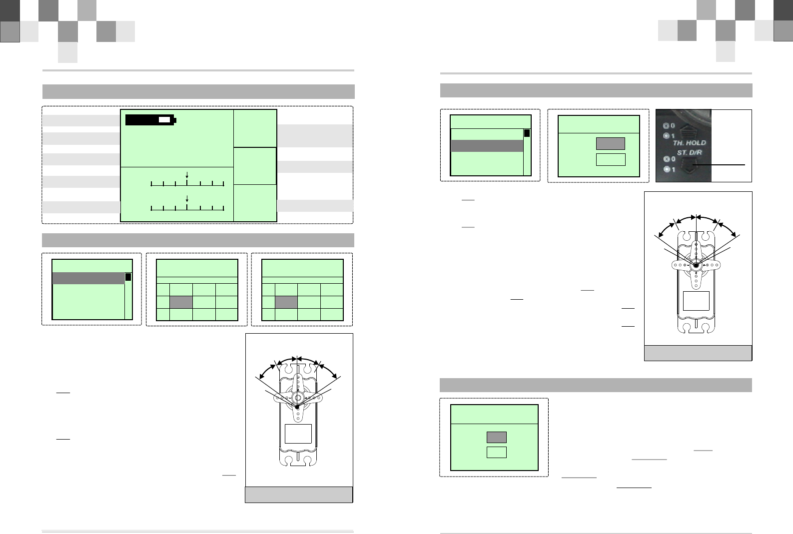
2.3 Main-Menu Function
10.2v D/R:
7 0
HLD:
O F F
MOD:
H R F
S T .
T H .
Voltage
Model Name
Timer
Steering Trim
Throttle Trim Modulation
Throttle Hold
Steering
Dual Rate
M00:mod00
T_I:00:00
F u n c t i o n 1 0 . 2 V F u n c t i o n 1 0 . 2 V
1:EPA
2:D/R
3 : S _ T R I M
4 : R E V
100%120%100%
E P A 1 0 . 2 V E P A 1 0 . 2 V
S T T H A U X
120%100%80%
F
B
1 0 0 % 1 2 0 % 1 0 0 %
2.6 S_TRIM
S _ T R I M 1 0 . 2 V S _ T R I M 1 0 . 2 V
S T :
T H : 0
0
--Use this function to adjust the neutral position of
the steering and throttle servos.
--SUB TRIM adjusting value range: -100-100
Default is 0
1.Press “ENTER” to see FUNCTION MENU.
2.Press “+” or “-“ to choose TRIM, and press
“ENTER” to enter SUB TRIM adjusting interface.
3.Press “+” to increase and “-” to decrease
SUB TRIM value.
4.Press “EXIT”to save your setting and leave SUB TRIM interface, and back to the
function menu interface.
TERMS: ST-STEERING, TH-THROTTLE
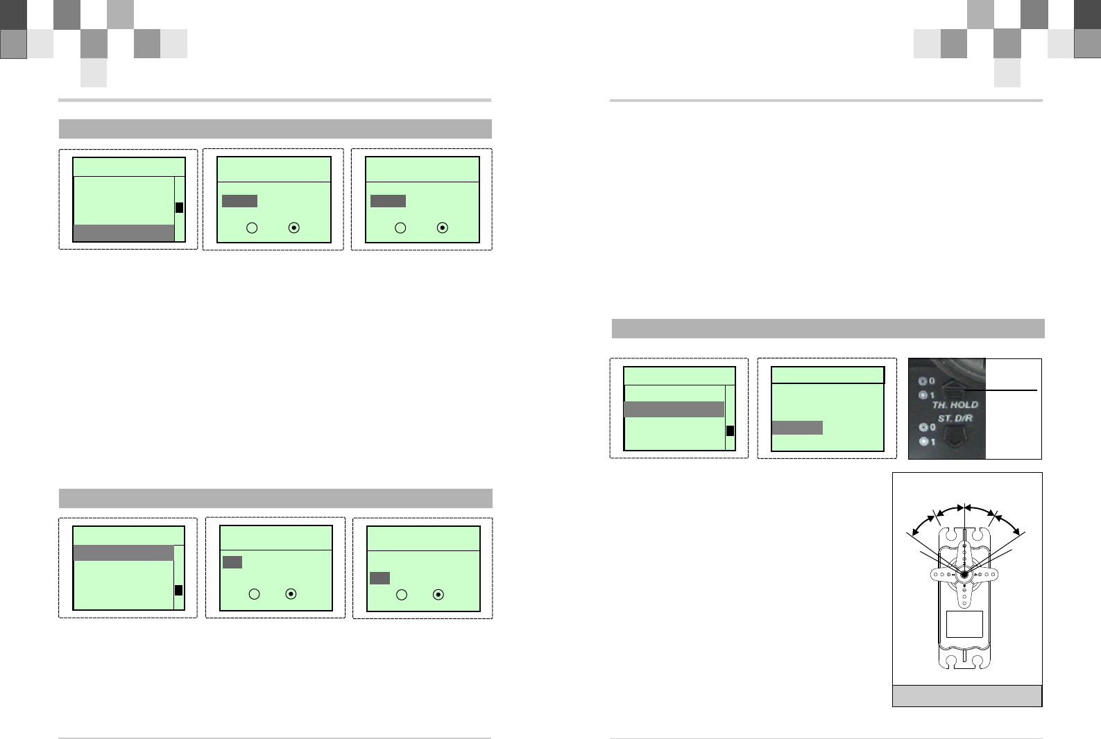
2.5 D/R
--D/R is used to change the action range of steering
servo when turning the steering wheel. Increasing D/R
will make the steering wheel action more sensitive.
--D/R adjusting value range: 0~120%, POS0
default value is 100%,POS1 default value is 70%.
--Press the ST.D/R dial to select POS0 or POS1, and
the value will display in the LCD when it is on the main
screen.
1.Press “ENTER” to see FUNCTION MENU.
2.Press “+” or “-“ to choose D/R, and press
“ENTER” to enter D/R adjusting interface.
3.Press “+” to increase and “-” to decrease D/R
value.
4.Press “EXIT”to save your setting and leave D/R
interface, and back to the function menu interface.
TERMS: POS-POSITION
S T D / R 1 0 . 2 V S T D / R 1 0 . 2 V
POS0:
POS1: 100%
70%
SERVO
050%
100%
120%
50%
100%
120%
RIGHT
FWD
LEFT
BACK
ST. D/R
F u n c t i o n 1 0 . 2 V F u n c t i o n 1 0 . 2 V
1 : E P A
3 : S _ T R I M
4 : R E V
2:D/R
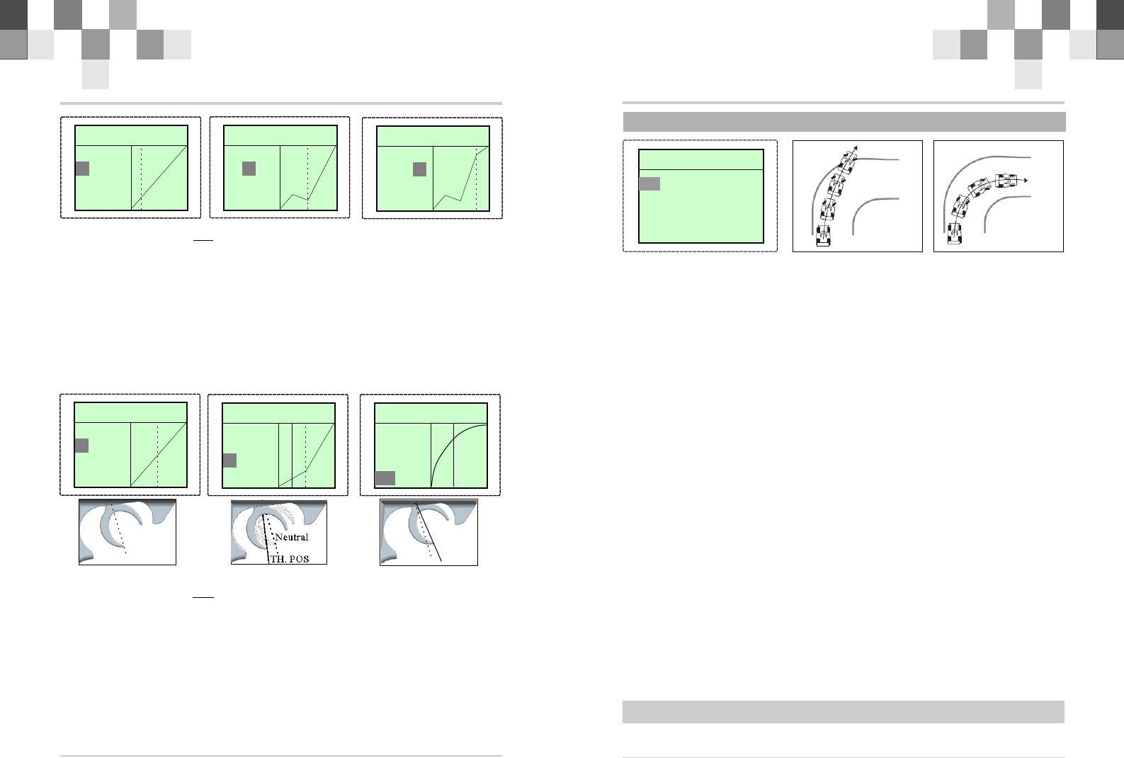
2.9 TH_CURV
TH CURV THROTTLE CURVES
This function makes the throttle high side and brake side direction servo operation
quicker or milder. It has no effect on the servo maximum operation amount. For the high
side, selection from among three kinds of curves (EXP/VTR/CUR) is also possible.
Note: When the course conditions are good and there is no sense of torque at the power
unit, set each curve to the + side (quick side). When the road surface is slippery and the
drive wheels do not grip it, set each curve to the - minus (mild) side.
Note: Brake side only has EXP curves.
1 Press “ENTER” to see FUNCTION MENU
2 Use the +/- Keys to select the TH CURV function and press ENTER.
3 Press ENTER to select a setting.
4 Use the +/- Key to change the value.
5 Press EXIT to save and return to FUNCTION MENU, press EXIT again to return to the
Main Screen.
STEERIN G STEERIN G
M:0 %
H:100%
T H _ C U R V 1 0 . 2 V
M : E X P
4 3 R :
B R : 0
STEERIN G STEERIN G
M:0 %
H:100%
T H _ C U R V 1 0 . 2 V
Neutral
Neutral
Quick forward(R:0~100) Mild forward(R:-100~0)
STEERIN G STEERIN G
M:0 %
H:100%
T H _ C U R V 1 0 . 2 V
Neutral
Mild backward(BR:-100~0)
TH. POS
TH. POS
Adjustment method for EXP curve
--Select EXP at setup item “M”
--Select setup item “R” and make the following adjustments:
1.Forward side adjustment:
Use the (+) button to adjust the + side when you want to quicken the rise and use the(-)
button to adjust the - side when you want to make the rise milder.
2.Brake side adjustment:
Select the setting item "BR" by ENTER button and use the (+) button to adjust the + side
when you want to quicker the rise and use the (-) button to adjust the - side when you want
to make the rise milder.
3.When ending setting, return to the initial screen by pressing the EXIT.
M : E X P
- 3 2 R :
B R : 0
M : E X P
R : - 3 2
: - 8 0B R
R/C Introduction Manual 10
R/C Introduction Manual
9
This function is used to change the sensitivity of the steering servo around the neutral
position. It has no effect on the maximum servo travel.
Note: When the setting is not determined, or the characteristics of the model are
unknown, start with 0% ( when EXP is set to 0%,servo movement is linear)
1.Press “ENTER” to see FUNCTION MENU
2.Use the +/- Keys to select the ST CURV function and press ENTER.
3.Use the +/- Key to change the value.
4.Press EXIT to save and return to FUNCTION MENU, press EXIT again to return to the
Main Screen.
STEERING CURVER adjusting value range: -100%~+100% Default is 0%(Linear)
Steering EXP adjustment
1.When you want to quicken steering operation, use the (+) button to adjust the + side.
When you want to make steering operation milder, use the (-) button to adjust the - side.
2 .When ending setting, return to the function menu by pressing the (EXIT) button .
TERMS: M-MODE, R--RATE
2.7 REV
This function reverses the direction of operation of
the servos related to transmitter steering, throttle, and
channel 3 operation.
1.Press “ENTER” to see FUNCTION MENU.
2.Press “+” or “-“ to choose REVERSE, and
press “E NTER” to enter REVERSE adjusti ng
interface.
3.Press “ENTER” to choose each Channel.
4.Press “+” to increase and “-” to choose
“REV” or “NOR”.
R E V E R S E 1 0 . 2 V R E V E R S E 1 0 . 2 V
T H A U X S T
REV
NOR
5.Press “EXIT”to save your setting and leave REVERSE interface, and back to the
function menu interface.
Note: However, when the position set by trim or sub trim shifts from the center, the
center becomes the opposite side.
TERMS: ST-STEERING, TH-THROTTLE,AUX-AUXILLIARY
2.8 ST_CURV
S T _ E X P 1 0 . 2 V
M : E X P
R : 0 %
S T _ E X P 1 0 . 2 V
F u n c t i o n 1 0 . 2 V F u n c t i o n 1 0 . 2 V
5 : S T C U R V
6 : T H C U R V
7:ABS
8 : M O D E L
M : E X P
R : 5 0 %
R/C Introduction Manual 12
R/C Introduction Manual
11
Adjustment method for VTR curve
--Select VTR at setup item “M”
--Select setup item “R” and make the following adjustments:
1.Forward side adjustment:
Use the (+) button to adjust the + side when you want to quicken the rise and use the(-)
button to adjust the side when you want to make the rise milder.
2.Curve switching point adjustment:
When you want to change the curve switching point relative to the throttle trigger,
select the setting item "P" by ENTER button, and use the (+) and (-) buttons to move to the
point you want to set.
Adjustment method for CUR curve
--Select CUR at setup item “M”
--Select setup item “R” and make the following adjustments:
1.Curve setup:
- Select the setting item "1:" (1st point), by ENTER button and use the (+) and (-)
buttons to set the 1st point.
- Set the throttle curve by sequentially setting "2:" (2nd point)~ "3:" (3th point).
2.When ending setting, return to the initial screen by pressing the EXIT
TERMS: M-MODE, R-RATE,BR-BRAKE,VTR-VERTICAL,CUR-CURVES
P-TRIGGER POS ,1~3-Curves point 1~3.
STEERIN G STEERIN G
M:0 %
H:100%
T H _ C U R V 1 0 . 2 V
M:CUR
2 3
R : 25
1
BR:0
STEERIN G STEERIN G STEERIN G STEERIN G
M:0 %
H:100%
STEERIN G STEERIN G
M:0 %
H:100%
M:VRT
: 5 0
R : 5 0
P
B R : 0
STEERIN G STEERIN G
M:0 %
H:100%
Neutral
Neutral
Forward side Forward side
TH. POS
STEERIN G STEERIN G
Neutral
Quick backward(BR:0~100)
TH. POS
TH_CURV 10.2V
T H _ C U R V 1 0 . 2 V
M:CUR
1 3
R : 88
2
BR:0
M:CUR
1 2
R : 88
3
BR:0
T H _ C U R V 1 0 . 2 V
TH_CURV 10.2V
T H _ C U R V 1 0 . 2 V
M:VRT
P : 5 0
: 2 5R
B R : 0
M:VRT
P : 5 0
R : 2 5
: 4 5B R
2.10 ABS
A B S 1 0 . 2 V
Without ABS With ABS
ABS--- Anti-Lock Brake System
When the brakes are applied while cornering with a 4 Wheel Drive or other type of
vehicle, under-steer may occur. The generation of under-steer can be eliminated and
corners can be smoothly cleared by using this function.
- When the brakes are applied, the throttle servo will pulse intermittently. This will
have the same effect as pumping the brakes in a full size car.
- The brake return amount, pulse cycle, and brake duty can be adjusted.
- The region over which the ABS is effective can be set according to the steering
operation.
1.Press “ENTER” to see FUNCTION MENU
2.Use the +/- Keys to select the ABS function and press ENTER.
3.Press ENTER to select PT item. Use +/- to change the value. Range: 0%~100%..
4.Press ENTER to select WD item. Use +/- to change the value. Range: 0%~100%.
5.Press ENTER to select CY item. Use +/- to change the value. Range: 0~30.
6.Press ENTER to select DL item. Use +/- to change the value. Range: 0~100.
7.Press ENTER to select DT item. Use +/- to change the value. Range: 0~100%.
8.Press ENTER to select SM item. Use +/- to change the value. Range: 0~100%. If this
value is 0, disable the steering mix.
9.Press ENTER to select MODE item. Use +/- to change INH、 TH、 AUX or TH&AUX.
10.Press EXIT twice to save and return to FUNCTION MENU, press EXIT again to return
to the Main Screen.
TERMS:
PT-Operation Throttle Trigger point
WD-Brake return amount. Sets the rate at which the servo returns versus trigger
operation for brake release. When set to 0%, the ABS function is not performed.
CY-Cycle speed. The smaller of the set value, the faster the pulse cycle.
DL-Delay amount. Sets the delay from brake operation to ABS operation. When set to
0%, the ABS function is activated without any delay.
SM-Steering Mix
DT-Cycle duty ratio. Sets the proportion of the time of the brakes are applied and the
time of the brakes are released by pulse operation.
MODE-If it is selected to INH, the function disable. If it is selected to TH, the ABS
function for THROTTLE brake. When it is selected to AUX, the ABS function for the AUX
channel. If it is selected to TH&AUX, the ABS function for both THROTTLE and AUX.
NOTE: the AUX and TH&AUX can select only the Brake MIX set to TH.
WD:50
DL:0
DT:1
PT: 1 0 %
C Y : 1 5 %
S M : 0
MODE:INH
R/C Introduction Manual 14
R/C Introduction Manual
13
2.11 MODEL
M O D E L 1 0 . 2 VM O D E L 1 0 . 2 V
E D T C P Y SEL
MDL.N :
Mo d0 0
“ENTER” “+ or -”
!Press “ENTER” in the power on interface, and enter function menu interface. Press
“+” or “-“ to choose MDL, and press “ENTER” to enter MODEL adjusting interface.
1.Press “ENTER” to choose “mod00”.(SEL)
2.Press “+” or “-”to choose “mod00~mod15”
3.Press “EXIT”to save your setting and leave SEL interface, and back to the function
menu interface.
MOL.N: A
“ENTER” “+ or -”/“ENTER”
1.Press “+” or “-”to choose “EDT”.
2.Press “ENTER” to enter rename mode ,Press “+” or “-”to choose
“0.1.2....I”
3.Press “ ” to save your modified and return to the MODEL Screen..
4.Press “EXIT”to save your setting and leave EDT interface, and back to the function
menu interface.
S T UVWXYZ
J K LMNOP Q R
0 1 2 3 4 5 6 7 8 9
AB C DE F GH I
M D L . N :
A |
R S T U V W X Y Z
IJKLMNOPQ
0 1 2 3 4 5 6 7 8 9
AB C D E F G H
“ENTER” “+ or -”
1.Press “+” or “-”to choose “CPY”.
2.Press “ENTER” to enter copy mode ,Press “+” or “-”to choose
“Mod01....Mod15”
3.Press “ENTER”to save your setting and Press “EXIT”leave CPY interface, and
back to the function menu interface.
MODEL 10.2VMODEL 10.2V
E D T C P Y SEL
MDL.N :
Mo d0 0
M O D E L 1 0 . 2 VM O D E L 1 0 . 2 V
E D T C P Y SEL
MDL.N :
Mo d0 1
MODEL 10.2VMODEL 10.2V
MDL.N :
Mo d0 0
S E L C P Y E D T
MOL.N: A
S T UVWXYZ
J K LMNOP Q R
0 1 2 3 4 5 6 7 8 9
AB C DE F GH I
M D L . N :
ADAM|
R S T U V W X Y Z
IJKLMNOPQ
0 1 2 3 4 5 6 7 8 9
A B C D E F G H
ENTER
M O D E L 1 0 . 2 VM O D E L 1 0 . 2 V
E D T C P Y SEL
MDL.N :
Mo d0 0
MODEL 10.2VMODEL 10.2V
E D T C P Y SEL
MDL.N :
Mo d0 0
M O D E L 1 0 . 2 VM O D E L 1 0 . 2 V
E D T C P Y SEL
MDL.N :
Mo d0 1
M O D E L 1 0 . 2 VM O D E L 1 0 . 2 V
MDL.N :
Mo d0 0
MODEL 10.2VMODEL 10.2V
MDL.N :
Mo d0 0
M O D E L 1 0 . 2 VM O D E L 1 0 . 2 V
S E L E D T CPY S E L E D T C P Y S E L E D T CPY
C P Y T O
Mo d0 1
MDL.N :
Mo d0 0
C P Y T O
Mo d1 5
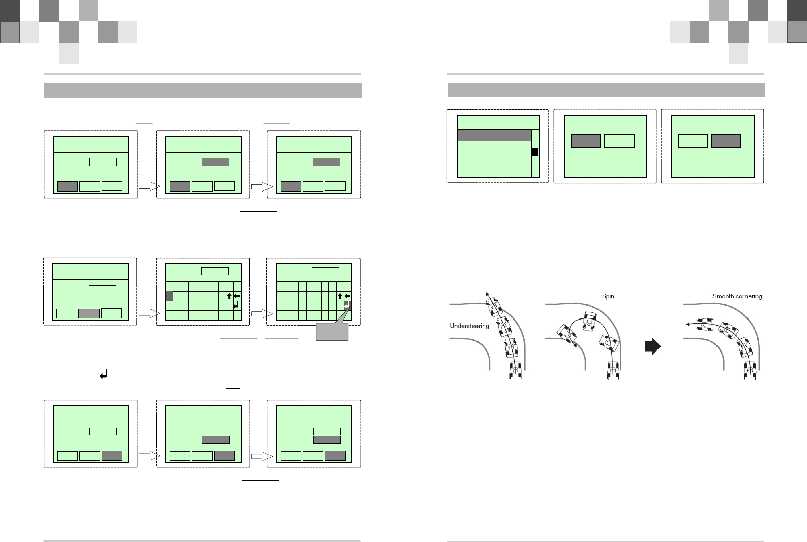
2.12 SPD
This function include tow items: STEERING SPEED and THROTTLE SPEED.
1.Press “ENTER” to see FUNCTION MENU
2.Use the +/- Keys to select the SPEED function and press ENTER.
3.Press ENTER to select a setting.
4.Use the +/- Key to change the value.
5.Press EXIT twice to save and return to FUNCTION MENU, press EXIT again to return
to the Main Screen.
1.STEERING SPEED
S P E E D 1 0 . 2 V S P E E D 1 0 . 2 V
S T
T H
SPD.FL: 0 %
SPD.BK: 0 %
Steering without speed Steering with speed
--Quick steering operation will cause momentary under steering, loss of speed, or
spinning. This function is effective in such cases.
-- This function limits the maximum speed of the steering servo. (Delay function)
-- The steering speed when the steering wheel is operated (TURN direction) and
returned (RETN direction) can be independently set.
-- If the steering wheel is turned slower than the set speed, the steering servo is not
affected.
F u n c t i o n 1 0 . 2 V F u n c t i o n 1 0 . 2 V
9 : S P E E D
1 0 : A T S
11:MODULATE
1 2 : B R _ M I X
S P E E D 1 0 . 2 V S P E E D 1 0 . 2 V
S T
T H
S P D . F L : 0 %
2.13 ATS
ATS Automatic Start
When the throttle trigger is set to full throttle simultaneously with starting when the
track is slippery, the car wheels will spin and the car will not accelerate smoothly. When the
Start function is activated, merely operating the throttle trigger slowly causes the throttle
servo to automatically switch from the set throttle position to a preset point so that the
tires do no loose their grip and the car accelerates smoothly.
Throttle without ATS Throttle with ATS
- When the throttle trigger is moved to the preset trigger position (TRI), the throttle
servo moves to the preset position (POS).
- When the throttle trigger is operated slowly so that the wheels will not spin, the car
automatically accelerates to the set speed.
- This function is effective only for the first throttle trigger operation at starting. This
function has to be activated before every start.
- When the throttle trigger is returned slightly, the Start function is automatically
deactivated and the set returns to normal throttle trigger operation.
1.Press “ENTER” to see FUNCTION MENU
2.Use the +/- Keys to select the ATS function and press ENTER.
3.Press ENTER to select TRI item. Use +/- to change the value. Range: -
100%~+100%..
4.Press ENTER to select POS item. Use +/- to change the value. Range: 0%~100%.
5.Press ENTER to select DLY item. Use +/- to change the value. Range: 0~100.
6.Press ENTER to select MOD item. Use +/- to change INH or RDY.
7.Press EXIT twice to save and return to FUNCTION MENU, press EXIT again to return
to the Main Screen.
TERMS:
TRI--- Throttle trigger position.
POS---Preset position
DLY---ATS Delay time
MOD---ATS Ready setting
A T S 1 0 . 2 V A T S 1 0 . 2 V
TRI: 1 %
P O S : 0 %
D L Y : 0
MOD: INH
F u n c t i o n 1 0 . 2 V F u n c t i o n 1 0 . 2 V
9 : S P E E D
1 1 : M O D U L A T E
1 2 : B R _ M I X
1 0 : A T S
A T S 1 0 . 2 V A T S 1 0 . 2 V
TRI: 1 %
P O S : 0 %
D L Y : 0
MOD: ACT
R/C Introduction Manual R/C Introduction Manual 1615
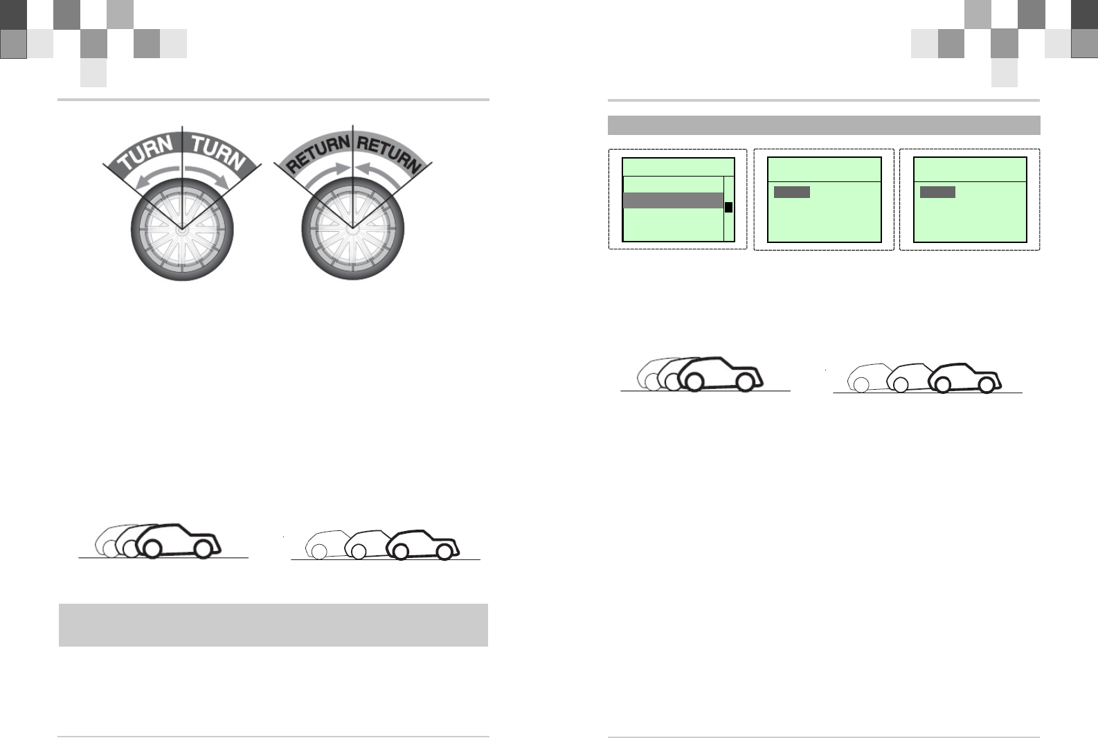
2.THROTTLE SPEED
- Sudden throttle trigger operation on a slippery road only causes the wheels to spin
and the vehicle cannot accelerate smoothly. Setting the throttle speed function reduces
wasteful battery consumption while at the same time permitting smooth, enjoyable
operation.
- Throttle servo (amp) operation is delayed so that the drive wheels will not spin even if
the throttle trigger is operated more than necessary. This delay function is not performed
when the throttle trigger is returned and at brake operation.
- Adjustment:
1.Select the TH button by +/- Keys.
2.Press Enter to select SPD. FL item.
3.Use +/- Keys change the value.
4.Press exit twice return to the function menu.
SPD.FL DELAY SPD.BK DELAY
Throttle without speed Throttle with speed
TERMS:
SPD.FL- SPEED FORWARD DELAY. Range:0~100%, default:0.
SPD.Bk- SPEED BACKWARD DELAY.Range:0~100%, default:0.
R/C Introduction Manual 18
2.17 TH HOLD
4.Firstly main channel setting. Select channel No. (ST, TH, AUX) by “+” or “-“. L
and R separately correspond to the rate of Left and Right servos of the main channel mix
5.Secondly sub channel setting. Select channel No. (ST, TH, AUX) by “+” or “-“. L
and R separately correspond to the rate of Left and Right servos selected in the sub
channel.
6.Third Press ENTER to select EN item. Use +/- to select “ON” to enable the function,
and “OFF” to disable the function.
7.Press EXIT twice to save and return to FUNCTION MENU, press EXIT again to return
to the Main Screen.
For example: current setting: ST: L 50% R 30%
TH: L 20% R 50%
EN: select “ON”
If throttle servo is 60% on the right and rudder servo is 50% on the right, and then
after setting, throttle servo is: 50*30%+60%*50%=45%. Throttle servo will act along with
the action of STEERING servo.
T H H O L D 1 0 . 2 V T H H O L D 1 0 . 2 V
VALUE: 0 %
TH.HOLD:
--This function allows the Throttle Servo to be set to
a percentage of the total travel range. This is an
alternative to using the motors choke when starting up
the model.Throttle hold can be performed by pressing
the switch to stop the engine. It can be performed for
accident braking. When pressing the switch, throttle
trigger doesn't work until the switch is pressed again.
1.Press “ENTER” to see FUNCTION MENU
2.Use the +/- Keys to select the TH HOLD function
and press ENTER.
3.Use the +/- Key to change the value.
4.Press EXIT twice to save and return to FUNCTION
MENU, press EXIT again to return to the Main Screen.
TERMS:
VALUE -- Throttle hold position. Range: -120% to
+120%.. Default value: 0%. SERVO
050%
100%
120%
50%
100%
120%
RIGHT
FWD
LEFT
BACK
TH.HOLD
2.16 MIX
M I X 1 0 . 2 V M I X 1 0 . 2 V
: L 5 0 R 5 0
S T : L 5 0 R 5 0
E N : ON OF F
S T
R/C Introduction Manual
17
B K - M I X 1 0 . 2 V
2.15 BK-MIX
: 1 0 0 %
E N : O N O F F
RATE
BR_MIX --BRAKE MIXING
When using a secondary brake system set the BRAKE MIX value to a percentage of the
Throttle Brake.
This mixing uses the 2nd channel to control the rear brakes and the 3rd channel to
control the front brakes. This function can be used in conjunction with the TH TRIM and TH
EPA to fine tune the power and balance of the overall braking system.
1.Press “ENTER” to see FUNCTION MENU
2.Use the +/- Keys to select the BR_MIX function and press ENTER.
3.Press ENTER to select a item.
4.Use the +/- Key to change the value.
5.Press EXIT twice to save and return to FUNCTION MENU, press EXIT again to return
to the Main Screen.
TERMS:
RATE -- the rate of brake between 3rd channel and 2nd channel. Default value: 0
120%.
EN -- the start or close switch of this function. Select “ON” to start the function,
and “OFF” to close the function
This function allow customer to apply mixing between the steering, throttle, and
channel 3channels.There are main channel and sub-channel in the MIX selection. The
servo travel value of the sub channel is changed along with the change of the main channel
according to the setting rate.
1.Press “ENTER” to see FUNCTION MENU
2.Use the +/- Keys to select the BR_MIX function and press ENTER.
3.Press ENTER to select a item.
F u n c t i o n 1 0 . 2 V F u n c t i o n 1 0 . 2 V
9 : S P E E D
1 0 : A T S
1 1 : M O D U L A T E
12:BR_MIX
B K - M I X 1 0 . 2 V
: 8 0 %
E N : O N O F F
RATE
F u n c t i o n 1 0 . 2 V F u n c t i o n 1 0 . 2 V
1 3 : M I X
1 4 : T H H O L D
1 5 : F / S
1 6 : N E U T R A L
M I X 1 0 . 2 V M I X 1 0 . 2 V
S T : L 5 0 R 5 0
: L 6 0 R 5 0
E N : ON OF F
T H
F u n c t i o n 1 0 . 2 V F u n c t i o n 1 0 . 2 V
13:MIX
15:F/S
1 6 : N E U T R A L
1 4 : T H H O L D
R/C Introduction Manual 20
2.20 SOUND
This function can open or close the buzzer sounding.
1.Press “ENTER” to see FUNCTION MENU
2.Use the +/- Keys to select the SOUND function and press ENTER.
3.Use the +/- Keys to select INH or ACT.
4.Press EXIT twice to save and return to FUNCTION MENU, press EXIT again to return to
the Main Screen
S O U N D 1 0 . 2 V S O U N D 1 0 . 2 V
SOUND:INH SOUND:INH
S Y S T E M
Reset System?
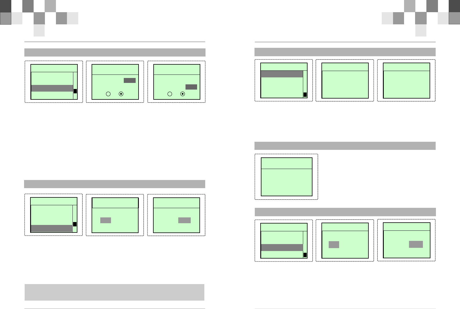
2.21 RESET
--All the setting in the system will be reset to the
default values by this reset function. It takes about 30
seconds.
1.Press “ENTER” to see FUNCTION MENU.
2.Use the +/- Keys to select the RESET function and
press ENTER.
3.Press ENTER to reset the N-4Q memory.
4.Press“ EXIT”twic e to save and retur n to
FUNCTION MENU, press EXIT again to return to the Main
Screen.
2.22 MODEL RESET
M _ R E S 1 0 . 2 V
Reset DATA ?
N O Y E S
R E A D Y
This function will reset the data of the current model memory to default values.
1.Press “ENTER” to see FUNCTION MENU
2.Use the +/- Keys to select the M_RES function and press ENTER.
3.Use the +/- Keys to select YES
4.Press ENTER to reset the data
5.Press EXIT twice to save and return to FUNCTION MENU, press EXIT again to return
to the Main Screen
R/C Introduction Manual
2.18 F/S
19
This function does not work in PPM mode. If the RF signal loss ,it should occur the
receiver adjust the Steering or Throttle or both to a preset value. The servo value of
Steering channel and Throttle channel in the fail status can be set through fail safe
function.
1.Press “ENTER” to see FUNCTION MENU
2.Use the +/- Keys to select the F/S function and press ENTER.
3.Press ENTER to select a item.
4.Use the +/- Key to change the value.
5.Press EXIT twice to save and return to FUNCTION MENU, press EXIT again to return
to the Main Screen.
TERMS:
ST -- To set the servo value of Steering channel. Range -120% to +120%. Default: 0%.
INH disable this channel Fail Save function. ACT---enable.
F / S 1 0 . 2 V
S T : 0 %
T H : 0 % I N H
E N : O N O F F
A C T
2.19 NEUTRAL
This function can calibrate the neutral of the STEERING wheel or THROTTLE trigger.
1.Press “ENTER” to see FUNCTION MENU
2.Use the +/- Keys to select the NEUTRAL function and press ENTER.
3.Use the +/- Keys to select YES.
4.Press ENTER to calibrate the neutral.
5.Press EXIT twice to save and return to FUNCTION MENU, press EXIT again to return to
the Main Screen
Note: Don't movement the STEERING wheel or THROTTLE trigger in the calibrate
procedure.
N e u t r a l 1 0 . 2 V
N O Y E S
READY
Set Neutral?
F u n c t i o n 1 0 . 2 V
13:MIX
1 4 : T H H O L D
16:NEUTRAL
15:F/S
F / S 1 0 . 2 V
S T : 0% A C T
T H : 2 0 %
E N : ON O F F
INH
F u n c t i o n 1 0 . 2 V
1 3 : M I X
1 4 : T H H O L D
1 5 : F / S
16:NEUTRAL
N e u t r a l 1 0 . 2 V
N O
O K
YES
Set Neutral?
F u n c t i o n 1 0 . 2 V F u n c t i o n 1 0 . 2 V
1 7 : S O U N D
1 8 : R E S E T
1 9 : M _ R E S
2 0 : T I M E R
S O U N D 1 0 . 2 V S O U N D 1 0 . 2 V
SOUND:ACT SOUND:ACT
F u n c t i o n 1 0 . 2 V
1 7 : S O U N D
1 8 : R E S E T
2 0 : T I M E R
1 9 : M _ R E S
M _ R E S 1 0 . 2 V
Reset DATA ?
N O
O K
Y E S

R/C Introduction Manual 22
3.1 Trim ADJ.
!Please start the motor or the engine while making the adjustment of these settings.
1 .Connect the receiver, servos, and other components and then turn on the power switches
to transmitter and receiver.
2.Be sure the Steering trim and Throttle trim on the transmitter are at their neutral position.
3.When turning on the transmitter, please make sure the transmitter antenna is
completely extended. Turn on the transmitter before turning on the receiver, while
turn off the receiver before turning off the transmitter.
Steering Trim
Steering neutral adjustments can be made by moving the steering trim knob to the left or
the right.
!Racers Tip
Always check and be sure the servo is at its neutral position before installing a servo. Adjust
the servo horn hole position and linkage so both are parallel. When a servo saver is used
place it as closer to center position as possible. Be sure the steering trim on the transmitter
at the neutral position.
!Trim Operation And Maximum Trav.
Changing the trim can effect the overall settings, when adjustments are made with the trims,
please recheck your installation for maximum servo travel.(Sreeting EPA right side and left
side ).
!When Trim movement goes to extremes
That means if you make a lot of trim movement to get a servo to the neutral position, please
reposition the servo horn or servo saver on the servo and inspect your linkage installation.
Throttle Trim
Throttle neutral adjustments can be made by moving the throttle trim to the left or the right.
! Racers Tip
When using a electronic speed control, please set the throttle trim to neutral and make
adjustments to the speed control. On a gas powered model, set the trim to neutral and
adjust the linkage to the point where carburetor is fully closed in accordance with the engine
instruction manual.
! Trim Operation and Travel
Trim adjustments will effect the overall servo travel, so please check the (back-ward)
movement after the adjustment
! When trim movement is goes to extremes
That means if you make a lot of the trim movement to get the servo to the neutral position,
please recenter the servo horn closer to the neutral position and inspect your throttle
linkage.
R/C Introduction Manual
21
2.23 TIMER
T I M E R 1 0 . 2 V
T : 0 m 0 s
MODE: I N H
Use the timer by selecting one of the two timers UP TIMER and DOWN TIMER., and if
the MODE is INH, It will close the TIMER Function.
1.Press “ENTER” to see FUNCTION MENU
2.Use the +/- Keys to select the TIMER function and press “ENTER”.
3.Press ENTER to select a item.
4.Use the +/- Keys to change the value
5.Press “EXIT” twice to save and return to FUNCTION MENU, press “EXIT” again
to return to the Main Screen
UP TIMER function
- Press “ENTER” to select the MODE. Use +/- Keys to select UP_T.(UP TIMER).
- The UP TIMER can be used to count the time from 0 minute 0 second to the stop
time. The stop time is set form from 0 minute 0 second to 99 minute 30 second.
- The first start operation will be linked to the throttle trigger.
- The passage of time is announced by sounding of a buzzer each minute after starting.
- The buzzer will sound 'B-B-B…' when the timer is up to the stop time.
DOWN TIMER function
- Press “ENTER” to select the MODE. Use +/- Keys to select DN_T.(DOWN TIMER).
- The DOWN TIMER can be used to count the time from preset time 0 minute 0 second.
The preset time is set form 0 minute 0 second to 99 minute 30 second.
- The first start operation will be linked to the throttle trigger.
- The passage of time is announced by sounding of a buzzer each minute after starting.
- The buzzer will sound 'B-B-B…' when the timer is down to the 0 minute 0 second.
F u n c t i o n 1 0 . 2 V
1 7 : S O U N D
1 8 : R E S E T
1 9 : M _ R E S
2 0 : T I M E R
T I M E R 1 0 . 2 V
T : 3 m 2 s
MODE:DN_T
R/C Introduction Manual 24
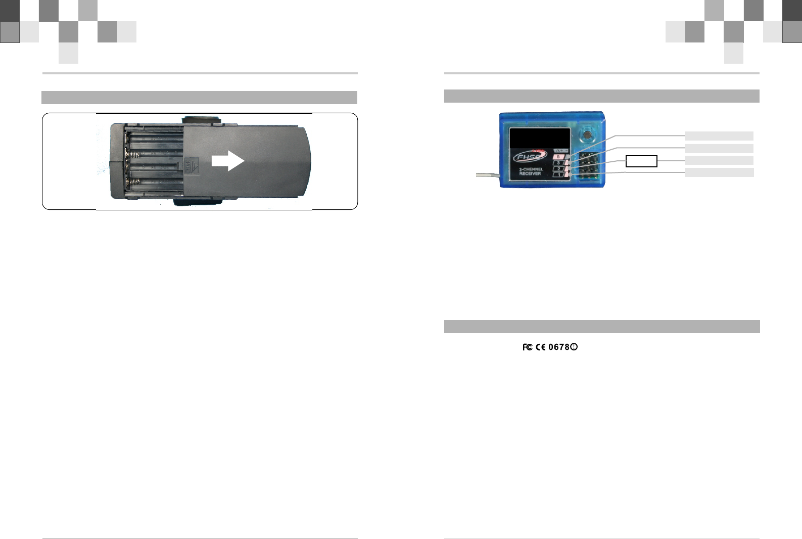
3.3 Connection between Receiver and Servos(2.4G)
2.4G Radio Data Transmission
1.Technology of FHSS 2.4G radio transmission and receiving
2.Working frequency is the worldwide universal frequency band of ISM ( Industrial
Scientific and Medical), free of charge, and the range is from 2.400 GHz to 2.483 Ghz.
3. Max transmitting power: 20dBm 100mA.
4. Max. receiving sensitivity: -93dBm.
5. Working current at transmitting end: 200mA ~ 300mA.
6. Working current at receiving end: < 50mA.
7. Data transfer rate : 19200 bit/Sec.
8. Working temperature: 0º to 70ºC.
R/C Introduction Manual
3.2 Handling Procedure For Batteries
23
! Battery Replacement
1.Remove the battery cover from the transmitter by sliding it in the direction of the arrow .
2. Remove the used batteries.
3.Load the new AA size batteries. Pay very close attention to the polarity marking and
reinsert accordingly.
4 .Slide the battery cover back onto the case.
! Caution
Always be sure your reinsert the batteries in the correct polarity order. If the batteries are
loaded incorrectly, the transmitter may be damaged.
When the transmitter is not used , always remember to remove the batteries. If the batteries
do happen to leak, clean the batteries case and contacts thoroughly. Make sure the contacts
are free of corrosion.
! Battery Disposal
Some countries require special handling of used of batteries ,please contact the agencies
responsible for recycling hazardous wastes in your local area.
! Battery low voltage alarm indicator.
Technology Data
TRANSMITTER
Channels: 3
Frequency: 2.4G
DC: 9.6V,≤150mA
Net weight: 360g
RECEIVER
Channels: 3
Frequency: 2.4G
DC: 4.5~5.5v,≤30mA
Net weight: 9.0g
ESC
+-
SERVO3(CH3)
SERVO1(ST.)
SERVO2(TH.)
BATT.( 4.8V)
This device complies with part 15 of the FCC rules. Operation is subject to the
following two conditions (1) this device may not cause harmful interference, and (2)
this device must accept any interference received, including interference that may
cause undesired operation.
Changes or modifications not expressly approved by the party responsible for
compliance could void the user's authority to operate the equipment.
XY3000/XY3100/XY300P/XY4000/8183
FCC Radiation Exposure Statement
The antennas used for this transmitter must be installed to provide a separation distance of
at least 20 cm from all persons and must not be collocated or operating in conjunction with
any other antenna or transmitter.