Guangzhou Chiyuan Electronic H-6Q 2.4 GHz Radio Control System User Manual H 6Q
Guangzhou Chiyuan Electronic Co.,Ltd 2.4 GHz Radio Control System H 6Q
User manual

数字比例遥控系统
Digital Proportional Remote Control System
Instruction Manual
H-6Q
Thank you for purchasing our R/C system
Before using, read this manual carefully
6-CH 2.4G Radio Control System

Table of Contents
1.0 Foreword
1.1 Declaration
1.2 Safety notice
1.3 Pre-flight checklist
2.0 Features and specifications
3.3 Binding
3.2 Transmitter functions (Rear)
3.1 Transmitter functions (Front)
3.0 Functionality
2.3 XY7000S receiver specifications
2.2 H-6Q transmitter features
3.5 Stick calibration
3.4 Menu buttons
3.8 Battery installation
3.7 Throttle stick configuration
3.6 Simulator port
4.0 Aircraft type
5.1 Display icons
5.2 Channel reverse (REV)
5.4 End point adjustment (EPA)
5.5 Timer
5.3 Dual rates (D/R)
6.0 Fixed wing aircraft/multicopter-
menu and settings
3.10 LCD screen functions
2.1 H-6Q transmitter specifications
2.4 XY7000S receiver features
3.9 LED backlight warning system
5.0 Helicopter- menu and settings
6.1 Display icons
6.2 Channel reverse (REV)
6.4 End point adjustment (EPA)
6.5 Timer
6.3 Dual rates (D/R)
目录
1.
1.1 要声明
1.2 安 注意事项
1.3 飞 前注意事项
2.0 特性与规格
3.3 连接线图和绑定
3.2 背面功能
3.1 正面功能
3.0 功能说明
2.4 机规格 XY7 00S接收
2.1 H-6 发射机特性
3.5 摇杆中位校正
3.4 面板功能
3.8 电池安装
3.7 左右手切换
3.6 练习模式
4.0 模式类型
5.1 功能菜单
5.2 反位设置
5.4 舵机行程量
5.5 计时器
5.3 大小舵量
6.0 固定翼功能菜单
3.10 开机界面
2.2 H-6Q发射机规格
2.3 接收机特性 XY7000S
3.9 LED灯演示功能
5.0 直升机功能菜单
6.1 功能菜单
6.2 反位设置
6.4 舵机行程量
6.5 计时器
6.3 大小舵量
1
2
2
2
2
3
3
3
3
3
4
4
4
5
5
6
6
6
8
8
9
9
10
10
11
11
12
13
13
13
14
14
15
10
16
16
16
16
17
17
17
17
17
18
18
18
19
19
20
20
20
22
22
23
23
24
24
24
25
25
26
27
27
27
28
28
29

2
1.0 Declaration
1.2 Safety notice
1.0 Foreword
3
1.3 Pre-flight checklist
2..1 H-6Q transmitter specification
2.0 Features and specifications
2.2 H-6Q transmitter features
2.4 XY7000S receiver features
2.3 XY7000S receiver specifications
H-6Q Instruction Manual
(1) This product is designed for experienced pilots aged 14 years of age or older.
(2) The user should operate the radio controlled aircraft at a legal, designated field.
(3) HiSKY accepts no responsibility for damage or injury caused by mis-operation,mis-use or
mis-control after purchase.
(4) If assistance is required, please contact the distributor or our customer service
representitives.。
(1) Follow the guidelines specified in this manual
Do not modify this transmitter in any way unless specified by this manual.
(2) Safe operation
Operate this device depending on your own skill level and your health status; refrain from
using this product if you feel feeble or fatigue. Do not operate this device under the
influence of drugs or alcohol.
(3) Flying location
Despite being highly reliable and advanced products, mechanical and electronic failures
may still happen. Do not operate the model aircraft in close proximity to people and other
obstacles; refrain from flying in averse weather or at night to avoid hurting yourself or
bystanders.
(4) Humidity
This product is made of highly complicated electronic and mechanical components, keep
the product in a dry environment and avoid humidity to avoid electrical and/or mechanical
damage.
(5) Heat
Avoid heat exposure; heat may cause electronic and mechanical components to warp or
fail, do not expose this product to excessive heat to prevent failure.
(1) Ensure that the battery packs on both the transmitter and receiver/aircraft are fully
charged prior to flight
(2) Ensure both the throttle stick and the throttle stick and the throttle trim of your stay at the
lowest positions before operation.
(3) The transmitter must be turned on prior to powering on the aircraft .To end your flight,
unplug the aircraft battery before turning the transmitter off. An incorrect order of
connection or disconnection may cause the loss of control of your aircraft.
(1) Utilizes 2.4GHz Frequency Hopping Spread Spectrum (FHSS) technology
(2) Collective-pitch helicopters and fixed-wing aircraft compatible
(3) Digital trim
(4) Dual rates on aileron, elevator and rudder.
(5) Swashplate mixing
(6) Low voltage warning
(1) Channels:6
(2) Resolution: 1024
(3) Frequency: 2.4GHz ISM frequency range
(4) Modulation: GFSK
(5) Spread spectrum mode:FHSS\
(6) Number of frequency channels:20
(7) Hopping rate: 240jumps/s
(8) Output power: <=20dBm
(9) Working current:<=150mA
(10) Operation voltage: 1.2V x 4 NiCad/NiMH
(11) Dimensions: 150mm x188mm x 70mm
(12) Net weight:322g
(1) 2.4GHz FHSS technology
(2) High reception sensitivity, high resistance to interference
(1) Channels:7
(2) Frequency: 2.4GHz ISM frequency range
(3) Modulation: PCM
(4) Spread spectrum mode: FHSS
(5) Operation voltage: 4.5-5.5V
(6) Operation current: <=30mA
(7) Net weight: 11.5g
(8) Product size: 41mm x 28mm x 14mm
H-6Q Instruction Manual
3.0 功能说明
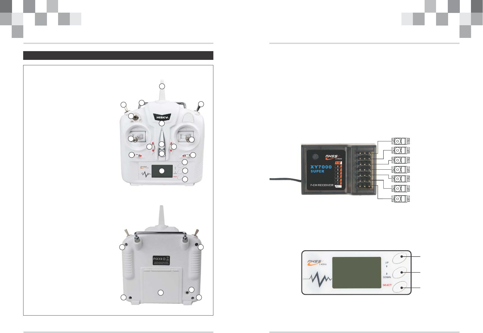
3.1 Front panel view
3.2 Rear view
3.3 Wiring diagram and binding procedure
Aileron servo
Rudder servo
Throttle servo
Elevator servo
Power
Undercarriage servo
Flap servo
3.4 Function keys in panel
There are 3funcfion keys on the H-6 panel, Details below:
1
2
3
4
5
6
7
8
9
10
11
12
13
14
15
16
17
18
1. Antenna
2. Handle
3. Helicopter mode: IDLE (0/1)
mode: CH5 Flap (0/1)
4. D/R (Aile Elve Rudd)
5. LED
6. Left stick
7.
8.
9. Eyelet
10. Power
11. LCD
12. Throttle hold
( mode:CH6 Undercarriage)
13. Right stick
14.
15
16. UP
17. DOWN
18. SELECT
Airplane
Digital trim
Digital trim
Airplane
Digital trim
Digital trim
1
2
3
4
5
6
1.
2.
3.
4.
5. Trainer port/DSC
6. Battery case cover
Screw 1
Screw 2
Screw 3
Screw 4
Binding:
Switch on the transmitter, reduce throttle to its lowest position and make sure the
alarm is off when powering on the receiver/aircraft. Press the bind button (if applicable)
until the green light turns, solid, signaling binding success.
Caution:
While binding, place the transmitter and receiver antennas in close proximity if possible;
make sure that there are no similar devices on bind mode within approximately 10 meters.
If the light flashes after the binding procedure is complete, retry the binding procedure
again until the light turns solid.
UP
DOWN
SELECT
H-6Q Instruction Manual H-6Q Instruction Manual
45
3.5 Stick calibration
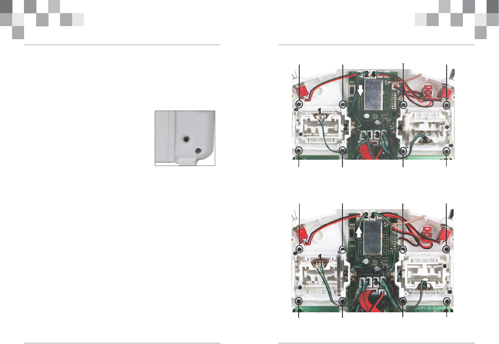
3.6 Trainer port (Digital Signal Converter, DSC)
This port is used to connect the transmitter to an
optional simulator on your computer. The trainer
cable and USB adaptor is sold seperately.
Instructions:
Attention:
1.Do not plug unauthorized devices into the DSC port
on the transmitter; doing so will void the warranty.
2.This device is compatible with R/C simulators only.
After simulator installation, plug the trainer cable into the
DSC port and the USB adaptor; then plug the USB adaptor
into the USB port on your computer.
3.7 Throttle stick configuration
To switch the throttle stick from the left column to the right (or vice versa),
a mechanical modification needs to be made:
Remove the 4 screws and rear cover to expose the base plate. The photo below shows the in
ternal below shows the internal views of right and left throttle setups.Using a phillips
screwdriver loosen and remove Screw A to adjust the throttle mode,then screw the Screw A.
Potentiometer cable connection in the corresponding positions are shown below. Replace the
rear cover when the mechanical switch is completed.
Left throttle stick
1
2
3
4
Right throttle stick
Center both control columns,simultaneously hold the “throttle” trim up and the
“rudder” trim left (mode 2); turn the transmitter on. The buzzer will sound four times,
release all trims and reduce the throttle column to its lowest position.
1
2
3
4
1
2
3
4
1
2
3
4
1
Screw A
H-6Q Instruction Manual H-6Q Instruction Manual
Screw A Screw A Screw A
Screw A Screw A Screw A Screw A
Screw A Screw A Screw A Screw A
Screw A Screw A Screw A Screw A
67
3.9 LED backlight warning system
(2)(3) (4)(1)
TIME:
H
D/R 0
MODE2
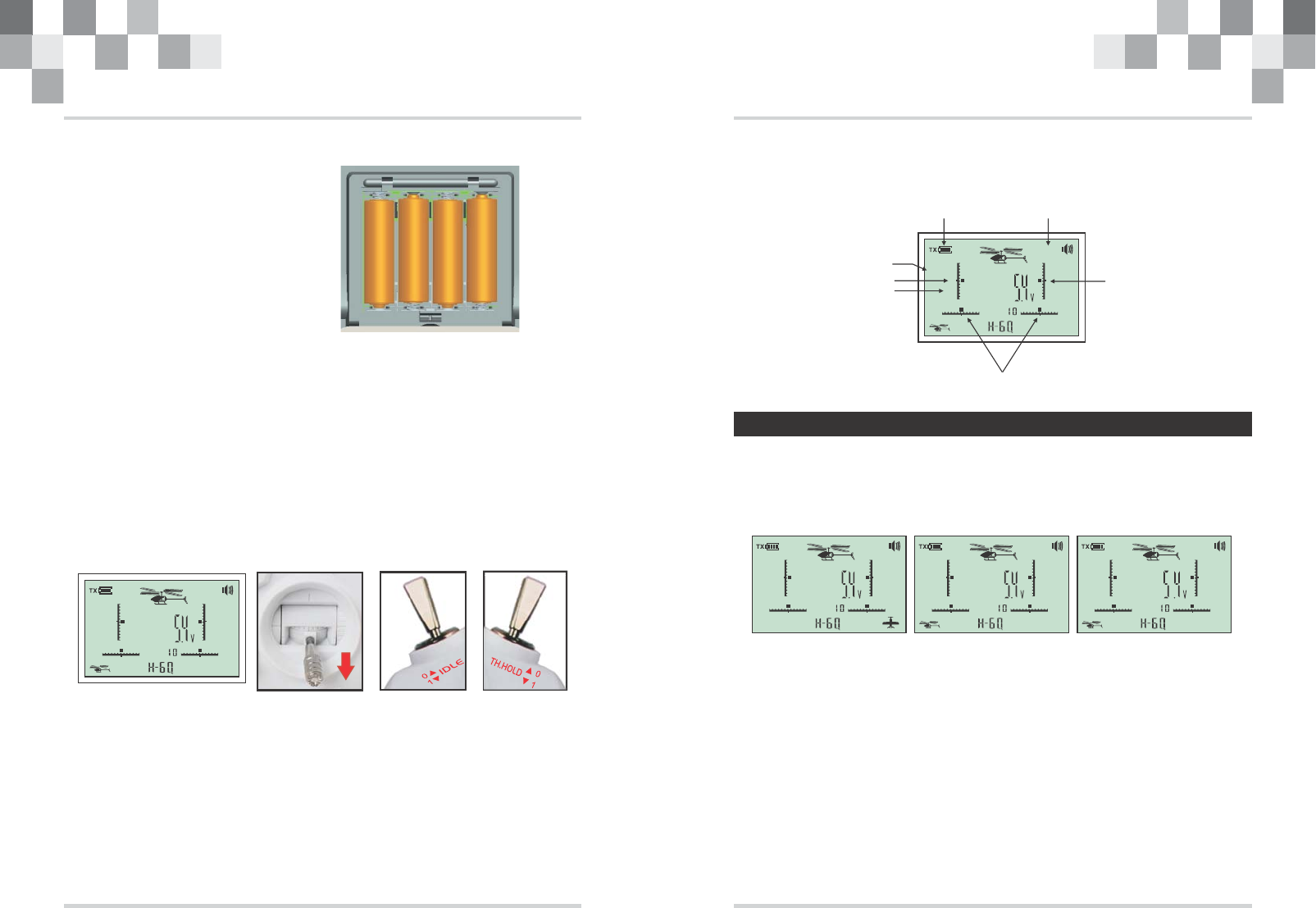
3.8 Battery installation
4x AA batteries are required to operate
the H-6Q, the polarities of which are
shown below
+ +-
-
+-
-
+
TIME:
H
D/R 0
MODE2
TIME:
H
D/R 0
MODE2
3.10 LCD screen functions
The icons and what they signify on the LCD screen are indicated below:
TX Voltage
Stick mode
electronic trim
model type
4.0 Aircraft type
There are 2 flight modes that can be selected on the H-6Q transmitter: helicopter and
fixed winged aircraft. These can be selected by double clicking the“UP”and“SELECT”
keys. On the LCD screen, “L” is fixed winged mode while “M/H” is helicopter mode
(as shown in the diagram below).
固定翼模式 直升机翼模式 直升机翼模式
Attention:
TIME:
D/R 0
MODE2
L
TIME:
D/R 0
MODE2
M
Dual rates
(1) The transmitter battery voltage is no less than 4V
(2) The throttle stick is at its lowest position
(3) The IDLE switch is set to “0”
(4) The Throttle hold (TH.HOLD) switch is set to “0”
The backlit LCD screen of the H-6Q serves also as a warning system.
Under normal operating conditions, the LED backlight is solid. If the backlight flashes and
there is an audible warning sound, please check that the following conditions are met on the
transmitter.
H-6Q Instruction Manual H-6Q Instruction Manual
electronic trim
electronic trim
“M” mode is suitable for the HCP80
“H” mode is suitable for the HCP100
“L” mode is suitable for the HFP80/HFP100/HMX120
89
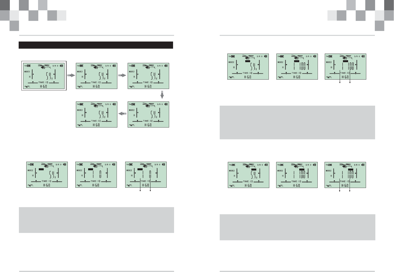
5.0 Helicopter mode
REV D/R
EPA
5.1 Function Menu
Channel Reverse Dual Rates
Timer
TX INTERFACE
5.2 Channel reverse
CH CH
Channel select Reverse
This function is used when the channel output opposites the desired output.
To toggle the dual rates menu and make adjustments, click the“UP”and“DOWN”buttons
to enter the functions menu, click“UP” or“DOWN” to scroll to the “D/R”option and
press“SELECT”to enter the dual rates menu. Press“SELECT”again to select the desired
channel and output by clicking“UP”or“DOWN”; after the selection is finalized, press
“SELECT”to exit to the channel selection, and simultaneously click the“UP”and“DOWN”
buttons to exit to the main menu.
REVREVREV
5.3 Dual rates
CH CH
This function allows one or more controls to have less (or more)control authority at the flick of
a switch. With the dual rate selected, the servo deflection will appear to have been reduced in
a manner similar to reducing the servo's end points.
5.4 End point adjustment
CH CH
End point adjustment or EPA, limits the amount of travel on the servo, or esc. For example, an
EPA limit of 50% means that only 50% of the servo/throttle throw is utilized even if the user
input is 100% of the travel on their transmitter.
EPA EPAEPA
D/R D/R D/R
To toggle the EPA function, click the “UP” and “DOWN” keys to enter the system menu, then click
“UP” or “DOWN” to scroll to the EPA option; press “SELECT” to enter the EPA menu, press
“SELECT” again to select the desired channel and to change its EPA settings by clicking “UP” or
“DOWN”; after the selection is finalized, press “SELECT” to exit to the channel selection, and
simultaneously click the “UP” and “DOWN” buttons to exit to the main menu.
To toggle the channel reversal function, click the “UP” and “DOWN” keys to enter the system menu,
then click “UP” or “DOWN” to scroll to the REV option; press “SELECT” to enter the REV menu,
press “SELECT” again to select the desired channel and to change its reversal settings by clicking
“UP” or “DOWN”; after the selection is finalized, press “SELECT” to exit to the channel selection,
and simultaneously click the “UP” and “DOWN” buttons to exit to the main menu.
EPA
Channel select
Channel select
H-6Q Instruction Manual H-6Q Instruction Manual
10 11
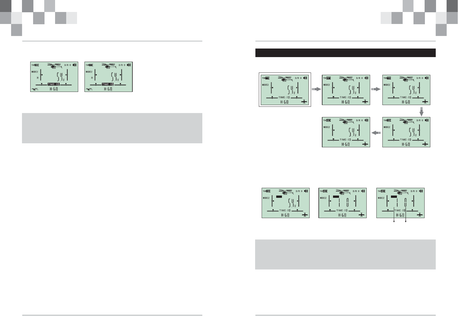
5.5 Timer
The timer provides audible warnings to the operator in order to control his/her flight time and
prolong battery life.
To set the timer: double click “UP” and “DOWN” simultaneously to enter the function menu,
then press “UP” or “DOWN” to select the “TIME” function; press “SELECT” to enter the setting
menu and select the time by pressing “UP” or “DOWN. After the time has been selected, press
“SELECT” to confirm, then hold down the “UP” and “DOWN” keys to return to the default menu.
Hold “UP” to start the timer, hold “DOWN” to reset.
6.0 Fixed wing aircraft menu
REV D/R
EPA
6.1 Function Menu
LLL
LL
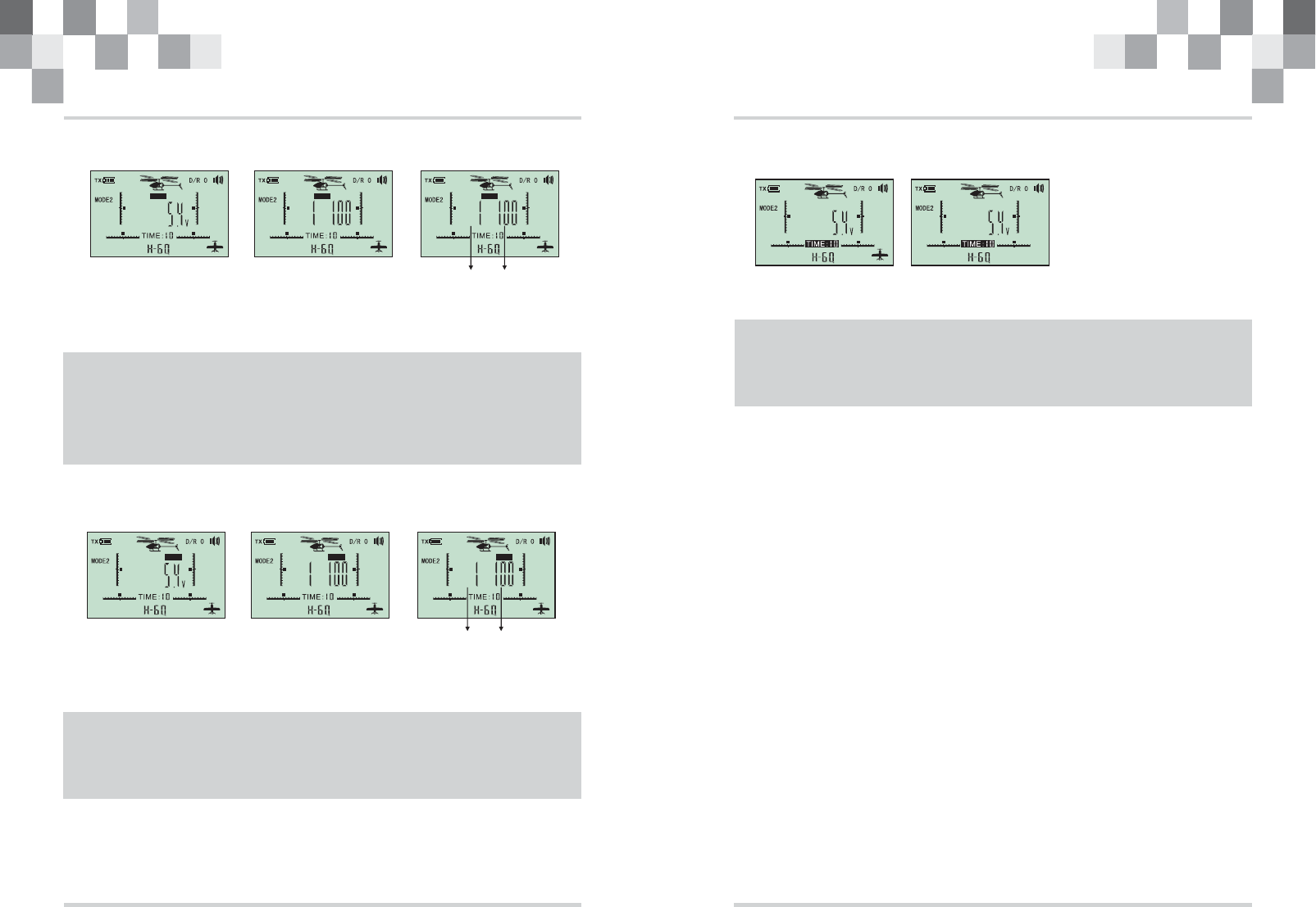
6.2 Channel reverse
CH CH
LL L
REV REV REV
Channel Reverse Dual Rates
Timer
TX INTERFACE
EPA
Channel select Reverse
This function is used when the channel output opposites the desired output.
To toggle the channel reversal function, click the “UP” and “DOWN” keys to enter the system menu,
then click “UP” or “DOWN” to scroll to the REV option; press “SELECT” to enter the REV menu,
press “SELECT” again to select the desired channel and to change its reversal settings by clicking
“UP” or “DOWN”; after the selection is finalized, press “SELECT” to exit to the channel selection,
and simultaneously click the “UP” and “DOWN” buttons to exit to the main menu.
H-6Q Instruction Manual H-6Q Instruction Manual
12 13
6.3 Dual rates
CH CH
L L L
D/R D/R D/R
6.4 End point adjustment
CH CH
EPA EPA
LLL
EPA
6.5 Timer
L L
Channel select
To toggle the dual rates menu and make adjustments, click the“UP”and“DOWN”buttons
to enter the functions menu, click“UP” or“DOWN” to scroll to the “D/R”option and
press“SELECT”to enter the dual rates menu. Press“SELECT”again to select the desired
channel and output by clicking“UP”or“DOWN”; after the selection is finalized, press
“SELECT”to exit to the channel selection, and simultaneously click the“UP”and“DOWN”
buttons to exit to the main menu.
This function allows one or more controls to have less (or more)control authority at the flick of
a switch. With the dual rate selected, the servo deflection will appear to have been reduced in
a manner similar to reducing the servo's end points.
Channel select
End point adjustment or EPA, limits the amount of travel on the servo, or esc. For example, an
EPA limit of 50% means that only 50% of the servo/throttle throw is utilized even if the user
input is 100% of the travel on their transmitter.
To toggle the EPA function, click the “UP” and “DOWN” keys to enter the system menu, then click
“UP” or “DOWN” to scroll to the EPA option; press “SELECT” to enter the EPA menu, press
“SELECT” again to select the desired channel and to change its EPA settings by clicking “UP” or
“DOWN”; after the selection is finalized, press “SELECT” to exit to the channel selection, and
simultaneously click the “UP” and “DOWN” buttons to exit to the main menu.
The timer provides audible warnings to the operator in order to control his/her flight time and
prolong battery life.
To set the timer: double click “UP” and “DOWN” simultaneously to enter the function menu,
then press “UP” or “DOWN” to select the “TIME” function; press “SELECT” to enter the setting
menu and select the time by pressing “UP” or “DOWN. After the time has been selected, press
“SELECT” to confirm, then hold down the “UP” and “DOWN” keys to return to the default menu.
Hold “UP” to start the timer, hold “DOWN” to reset.
H-6Q Instruction Manual H-6Q Instruction Manual
14 15
FCC Information and Copyright
This equipment has been tested and found to comply with the limits for a Class B digital device,
pursuant to part 15 of the FCC Rules.
These limits are designed to provide reasonable protection against harmful interference in a residential
installation. This equipment generates,
uses and can radiate radio frequency energy and, if not installed and used in accordance with the
instructions, may cause harmful interference
to radio communications. However, there is no guarantee that interference will not occur in a particular
installation. If this equipment does
cause harmful interference to radio or television reception, which can be determined by turning the
equipment off and on, the user is
encouraged to try to correct the interference by one or more of the following measures:
—Reorient or relocate the receiving antenna.
—Increase the separation between the equipment and receiver.
—Connect the equipment into an outlet on a circuit different from that to which the receiver is
connected.
—Consult the dealer or an experienced radio/TV technician for help.
This device complies with part 15 of the FCC Rules. Operation is subject to the
following two conditions:
(1)This device may not cause harmful interference, and
(2) this device must accept any interference received, including interference that may
cause undesired operation.
changes or modifications not expressly approved by the party responsible for compliance could
void the user's authority to operate the equipment.
Note: The manufacturer is not responsible for any radio or tv interference caused by unauthorized
modifications to this equipment. Such modifications could void the user’s authority to operate the
equipment.