Guangzhou Chiyuan Electronic X-3 3CH Radio Control User Manual X 3 mannual
Guangzhou Chiyuan Electronic Co.,Ltd 3CH Radio Control X 3 mannual
Users Manual
SERVO
020%
100%
120%
20%
100%
120%
RIGHT
FWD
LEFT
BACK
Xy300
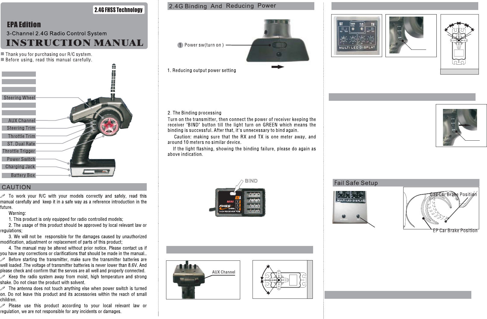
2. With the system hooked
up as shown, insert the
bind plug in the charge
plug receptacle.Turn on
the power of the receiver
(4.8~5.6v), and now
LED(xy300) should be
flashing indicating that
the receiver is ready to
AUX Channel Function(CH3)
SERVO
0
100%
100%
When pressing the “AUX”channel ,the servo moving clockwise,
pressing again, anticlockwise
BIND
ST.D/R
F/S
Funtion
Using this function to to adjust servo travel.
The default is 100%.When pressing D/R ,the front light flash,
and the value quickly switch to 70%.
Function
This F/S Funtion is protect your car or boat,when the signal become weak
or lost.
How to set
1.Make sure the RX power is enough.
2.Put trigger in brake position(above show). Keep the F/S button till
“ST.DR” become red.
3. Then release F/S button, the function finished.
Lock Function
When press “RF-TEST” button and “F/S” button together, the front
light become red, means locked.(Making sure you touch the ST.TRIM ,
TH.TRIM and D/R no response). Both press again, means unlocked.
1).Keep pressing RF-TEST button till the “ST.DR” light turn on RED.
Meanwhile the output power of transmitter reduce to lower mode 18dbm,
which done can save the power consumption.
2).When press the RF-TEST button again, the “ST.DR” light turn off, and
output power becomes normal 20dbm which can control more range.
RESET
Function
All the setting in the system will be
reset to the default values by
this reset function.
1.Press the ST.D/R and put the TH.TRIM
forward together, then turn on
the TX at the same time, the light of POWER
and ST.DR are flashing, means it is resetting.
2.Making sure this function work, you have to
turn off TX and turn on it again.
LOCK
Steering Dual Rates Choice
ST.D/R
TH.D/R
SERVO
020%
100%
20%
100%
RIGHT
FWD
LEFT
BACK
Trim Operation And Maximum Travel.
Changing the trim can effect the overall settings, when
adjustments are made with the trims, please recheck your
installation for maximum servo travel.
When Trim movement goes to extremes
That means if you make a lot of trim movement to get a servo
to the neutral position, please reposition the servo horn or
servo saver on the servo and inspect your linkage
installation.
Throttle Trim
Throttle neutral adjustments can be made by moving the
throttle trim to the left or the right.
Racers Tip
When using a electronic speed control, please set the
throttle trim to neutral and make adjustments to the speed
control. On a gas powered model, set the trim to neutral and
adjust the linkage to the point where carburetor is fully
closed in accordance with the engine instruction manual.
Trim Operation and Travel
Trim adjustments will effect the overall servo travel, so
please check the (back-ward) movement after the adjustment
When trim movement goes to extremes
That means if you make a lot of the trim movement to get the
servo to the neutral position, please recenter the servo
horn closer to the neutral position and inspect your
throttle linkage.
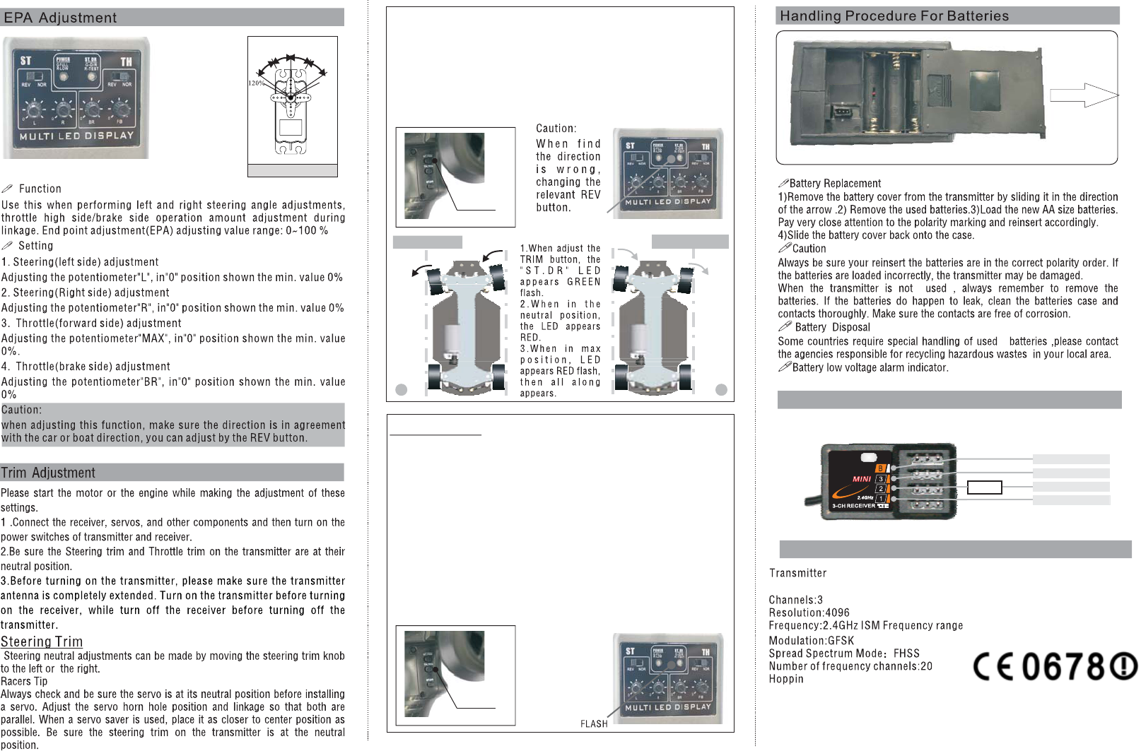
Receiver Connection Diagram
Technology Data
FLASH
TURN LEFT TURN RIGHT
1 2
120%
ESC
SERVO3(CH3)
SERVO1(ST.)
SERVO2(TH.)
BATT.( 4.8V)
ST.TRIM
TH.TRIM
g rate: 240 Jump/s
output power:<=20dbm
working current:<= 150mA
Working voltage:1.5V*4
NiCad/NiMH
Receiver
Channel:3
Frequency:2.4G ISM FREQUENCY
Spread spectrum mode: FHSS
Power:4.5-7.4V, <30 mA
Changes or modifications not expressly approved by the party responsible for
compliance could void the user's authority to operate the equipment.
FCC Radiation Exposure Statement
The antennas used for this transmitter must be installed to provide a separation distance of
at least 20 cm from all persons and must not be collocated or operating in conjunction with
any other antenna or transmitter.