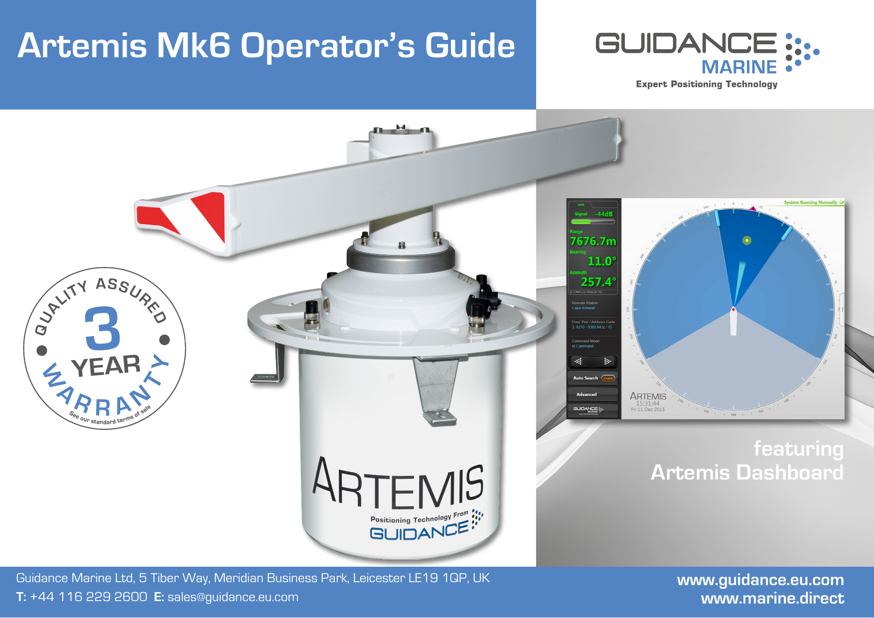
Guidance Marine ARTEMIS Marine Direction Finding X-BAND RADAR User Manual 94 0440 4 A Artemis Mk6 Operator s Guide
Guidance Marine Ltd. Marine Direction Finding X-BAND RADAR 94 0440 4 A Artemis Mk6 Operator s Guide
Contents
- 1. User Manual
- 2. Installers Guide User Manual
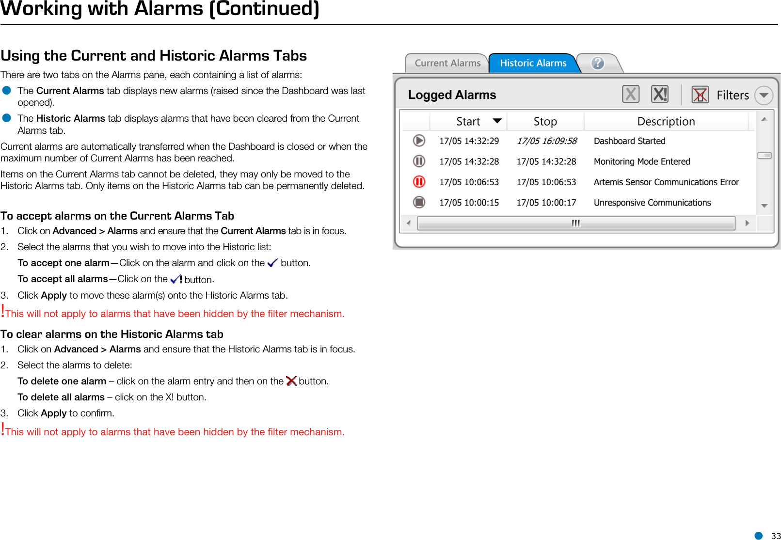
User Manual