Guidance Marine ARTEMIS Marine Direction Finding X-BAND RADAR User Manual 94 0440 4 A Artemis Mk6 Operator s Guide
Guidance Marine Ltd. Marine Direction Finding X-BAND RADAR 94 0440 4 A Artemis Mk6 Operator s Guide
Contents
- 1. User Manual
- 2. Installers Guide User Manual
User Manual
Guidance Marine Ltd, 5 Tiber Way, Meridian Business Park, Leicester LE19 1QP, UK
T: +44 116 229 2600 E: sales@guidance.eu.com
Artemis Mk6 Operator’s Guide
W
A
R
R
A
N
T
Y
S
e
e
o
u
r
s
t
a
n
d
a
r
d
t
e
r
m
s
o
f
s
a
l
e
Q
U
A
L
I
T
Y
A
S
S
U
R
E
D
3
YEAR
featuring
Artemis Dashboard
www.guidance.eu.com
www.marine.direct
Guidance Marine Ltd,
5 Tiber Way
Meridian Business Park
Leicester
LE19 1QP
UK
Tel: +44 116 229 2600
UK Support:
+44 116 229 2665
(365 days a year, 08:00 - 20:00 hours UTC)
customerservices.uk@guidance.eu.com
USA Support: +1 504 305-1120
customerservices.us@guidance.eu.com
Asia Support: +65 6734 6365
customerservices.sg@guidance.eu.com
Web: www.guidance.eu.com/customer-support
Copyright © 2016 Guidance Marine Limited. All Rights Reserved.
Copyright in the whole and every part of this document belongs to Guidance Marine Limited (the
“Owner”) and may not be used, sold, transferred, copied or reproduced in whole or in part in any
manner or form or in or on any media to any person other than in accordance with the terms of
the Owner’s Agreement or otherwise without the prior written consent of the Owner.”Windows”
is a trademark of Microsoft Corporation. All other brand or product names are trademarks or
registered trademarks of their respective companies or organisations.
Serial No:
Date of Shipment from UK:
Sensor Software Version: Dashboard Software Version:
Artemis Mk6 Operator’s Guide
Issue Date: 28/06/2016
Document No: 94-0440-4-A
l 3
Document History
Document Number Changes Issue Date
94-0440-4-A First release of Artemis Mk6 Operator’s Guide 28/06/2016

l 4
Introduction
System Overview ...................................................................................................... 6
Getting Started
Start Up and Shut Down .......................................................................................... 9
Start Up.............................................................................................................................................. 9
Shut Down ......................................................................................................................................... 9
Screen Contents ..................................................................................................... 10
Main Screen and Bird's Eye View (BEV) .......................................................................................... 11
System Status .................................................................................................................................. 12
Side Bar ........................................................................................................................................... 13
Hotkey Buttons ................................................................................................................................ 14
Menu Pane ....................................................................................................................................... 15
Display Options ...................................................................................................... 16
Display View ..................................................................................................................................... 16
Screen Layout Mode ........................................................................................................................ 16
Vessel Orientation ............................................................................................................................ 17
Basic Operation
Tracking Overview .................................................................................................. 19
Selecting a Remote Station .................................................................................... 20
To Select a Different Remote Station: .............................................................................................. 20
Adjusting the Scan Sector ...................................................................................... 21
To Adjust the Scan Sector: .............................................................................................................. 21
Tracking Information Quality ................................................................................... 22
DP Feeds ................................................................................................................ 23
To View DP Feed Details: ................................................................................................................. 23
Multi-Dashboard Artemis Systems
Artemis Dashboard – In Command Mode .............................................................. 25
Artemis Dashboard - Monitoring Mode .................................................................. 26
Support Information
Serial Numbers and Software Versions .................................................................. 28
Network Communications Settings ........................................................................ 29
Sensor Settings ...................................................................................................... 30
Using the On-Screen Keyboard ............................................................................. 31
To enable the on-screen keyboard .................................................................................................. 31
To use the on-screen keyboard ....................................................................................................... 31
Working with Alarms ............................................................................................... 32
International Standards Compliance ...................................................................... 34
System Specications ............................................................................................ 35
Index ....................................................................................................................... 37
Table of Contents
l 6
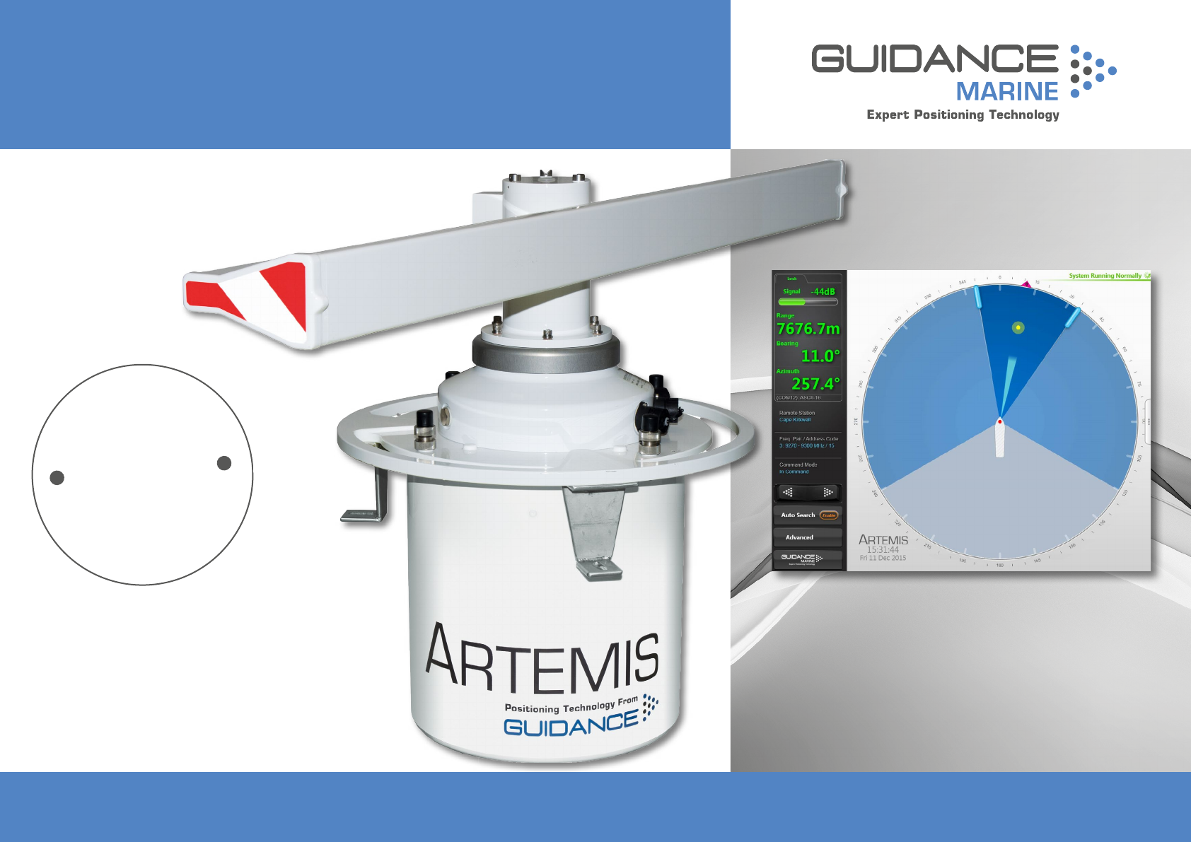
The Artemis microwave-based position reference system provides accurate positional data
to marine DP (dynamic positioning) control systems. It enables automated approach and
station keeping relative to a rig or platform, or to another vessel.
The standard Artemis system consists of:
• Two identical Antenna Units (or Sensors), user-configurable as a Mobile Station and a
Fixed Station.
• The Artemis Control PC, a Windows-based marine specification computer, running the
control software.
• Artemis Client PC(s), optional computers used where more than one installation of the
Artemis Dashboard software is required.
• Hand-held Operating Panel (or Pendant).
An alternative configuration - the Beacon system - involves the same components as the
standard system except for a Beacon Unit instead of a Fixed Station. A Beacon Unit does
not provide an Azimuth measurement.
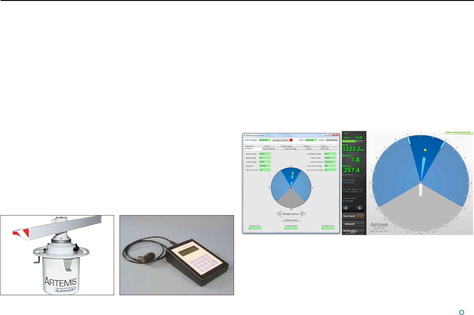
Antenna Units
The Mobile Station is mounted on the DP-Equipped vessel, ideally at the top of the main
mast. The Fixed Station is installed on a fixed platform if absolute positioning is needed or
on a moving platform or structure to provide relative positioning.
Hand-held Operating Panel (Pendant)
A hand-held unit that can be connected to a station or Beacon unit to read and set system
parameters during installation. It can also be used to view positional data once the system
is in operation. This is an optional diagnostic aid.
System Overview
Artemis Control Software
The following applications run on the Artemis Control PC, usually mounted on the bridge
near to the controls of the vessel’s DP system:
• Manager – This Windows service running on the Artemis Control PC can be configured
to run automatically after the PC powers up. It provides a single point of control for an
Artemis sensor through which the other components communicate.
• Service Interface – Used for system installation and maintenance, it allows network
communications to be configured and parameters on an Artemis Station to be viewed and
set. It displays the state of connected Artemis Dashboard(s) and can be used to take basic
control of the station.
• Dashboard – Used to control and monitor normal system operation. Up to five instances
of the Dashboard can run simultaneously on the Control PC and Client PCs, but only one
of these can exercise control at any given time; the others can only be used to monitor the
system.
An Antenna Unit (Mobile or Fixed Station) An Operating Panel
Artemis Service Interface Artemis Dashboard
Explosion-Proof Antenna Unit/Beacon
An antenna unit or beacon can be made safe for operation in hazardous zone 2 conditions
with the use of a pressurisation unit. This forces clean air into the housing of the antenna
unit or beacon to prevent the ingress of explosive or flammable gases that might otherwise
be ignited by electrical sparks. Contact Guidance Marine for details.
l 7
System Overview (Continued)
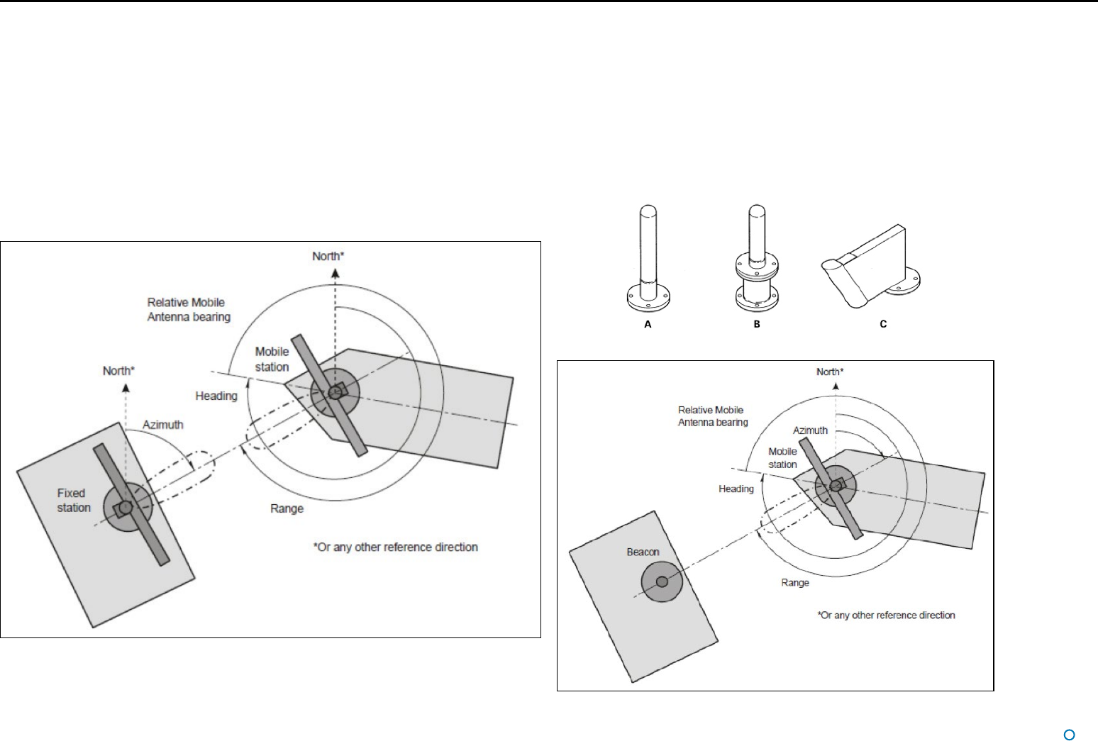
System Operation
In order to provide positional data to the vessel’s DP system, the Artemis system needs to
be “locked”. In this state, the antennae of the Fixed and Mobile Stations are facing each
other and automatically tracking by maintaining a continuous microwave link.
The distance between the sensors is obtained from the travel time of the microwave signal,
measured by means of coded interruptions in the continuous wave. The bearing of the
Fixed Station, with respect to the centre line of the vessel, is measured using a precision
shaft encoder.
The Fixed Station measures the Azimuth and reports it to the Mobile Station. The Azimuth
is the horizontal angle between a reference direction and the Mobile Station, with its vertex
at the Fixed Station.
Beacon Unit
Used instead of a standard rotating Fixed Station on a fixed platform for absolute
positioning, or on a moving platform or structure for relative positioning. The antenna
of a Beacon unit does not rotate, and three types of antenna are available for different
situations:
A. Omni directional antenna with 360° beam width
B. Semi-omni antenna with waveguide, 100° beam width
C. Horn antenna with 66° beam width
Layout of a Standard Artemis System
Different Types of Beacon Antenna
Layout of an Artemis Beacon System
The beam width of an antenna unit (Fixed or Mobile Station) is approximately 2°.
l 9
Start Up and Shut Down
Start Up
To Start Artemis Dashboard
1. Ensure that the local station is powered on.
2. Double-click on the Artemis Dashboard icon.
(Or run the Artemis Dashboard application from:
Start > All Programs > Guidance Marine Ltd > Artemis > Artemis Dashboard).
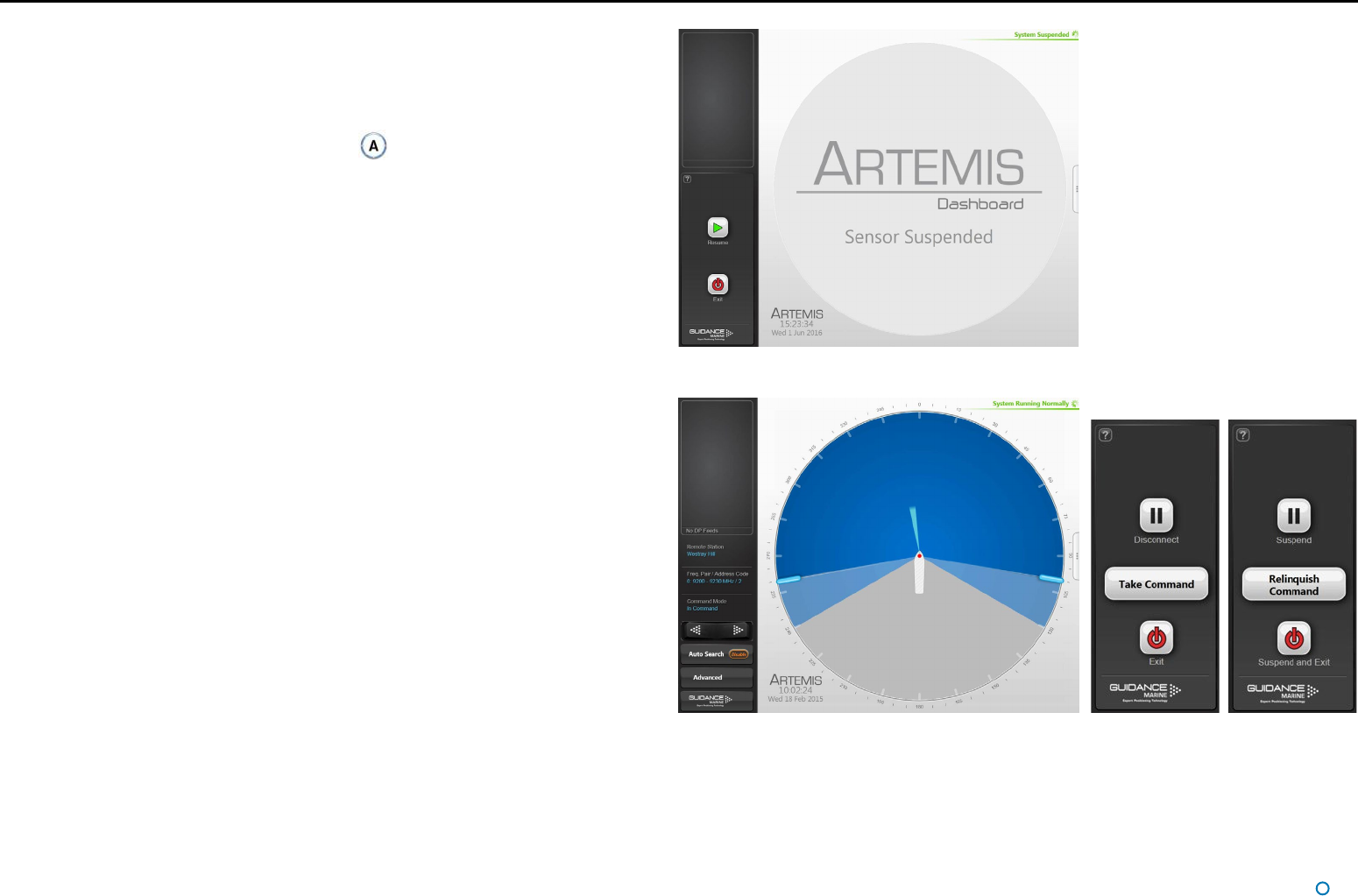
3. The Dashboard display screen will appear. If the sensor is currently suspended, the
main part of the screen will be greyed out. Click on the Resume button in the side bar
in order for the sensor to begin transmitting and for the results to be displayed on the
screen. If the sensor was already transmitting, any remote station to which it is locked
will be displayed straight away.
Shut Down
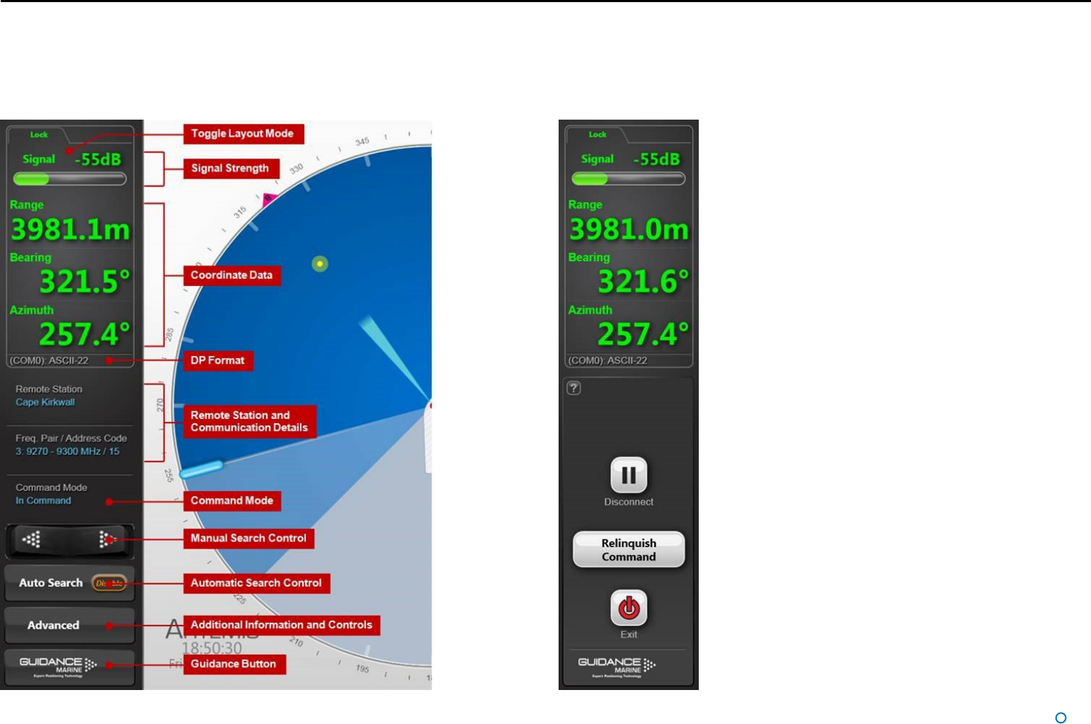
To Disconnect, Exit or Suspend
(Click on the Guidance button in the lower left corner of the screen. This reveals the
Guidance Home Menu, which contains different sets of buttons depending whether
the Dashboard is in command, and whether it is tracking a remote station. Buttons are
explained below.
• Disconnect - Ceases communications between the local station and the Dashboard
computer. The local station is unaffected and if tracking is in progress, it will
continue.
• Exit - Closes the Dashboard without affecting the sensor.
• Suspend – Only available when the Dashboard is in command and the local station is
not tracking a remote station. Places the local station into a ‘sleep mode’ in which it
ceases to transmit. The Dashboard remains active and connected to the sensor ready
for operations. This mode is suitable for use when travelling between locations.
• Suspend and Exit – Same as Suspend, except that it closes the Dashboard
program.
Dashboard screen with local station suspended
Dashboard screen with local station scanning Guidance Home Menu in
different contexts
Side Bar
l 11
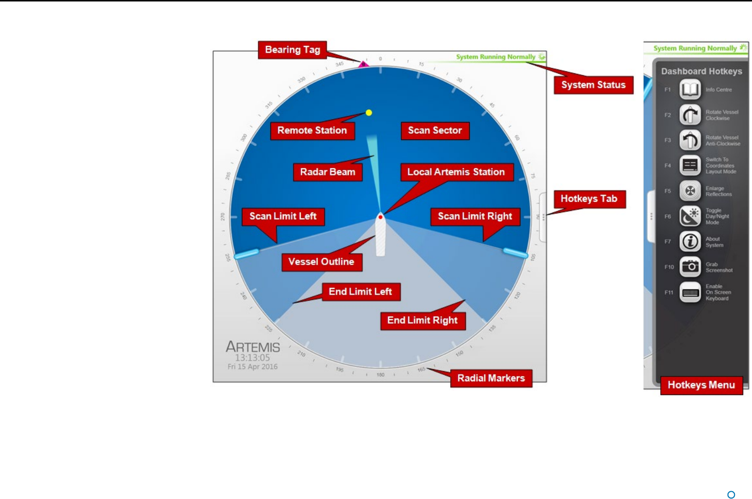
Main Screen and Bird's Eye
View (BEV)
The circular BEV depicts the operational area
of the Artemis system from above. The red dot
at the centre represents the local Antenna Unit
mounted on its vessel and the arc through which
it can rotate corresponds to the combined blue
areas. A grey exclusion zone can be configured
(using the End Limit parameters) if there is a
physical obstruction that prevents the antenna
from turning through 360°.
The current direction and movement of the radar
beam is indicated by the slim, light blue triangle.
If the local station is locked onto a remote
station, this is represented by a yellow dot. If
the remote station is configured as “Floating”
rather than “Fixed”, the outline of its vessel is also
shown (with its bow aligned to 0° azimuth).
Vessel Outlines
Where a vessel outline is shown, its direction
is significant, but its size, exact shape and the
position of the Artemis station within it are all
arbitrary and cannot be altered.
Scan Limits
If the local station is not locked onto a remote
station, and Auto Search is enabled, the beam
moves to and fro across the configured scan
sector. The size of this sector (the dark blue area)
can be adjusted (see Adjusting the Scan Sector
on page 21).
Radial Markers
These form an angular scale in degrees,
clockwise around the circumference of the BEV.
Zero is defined by the bow of the local vessel.
Screen Contents (Continued)
l 12
Screen Contents (Continued)
System Status
This consists of two fields:
Primary
The primary part of the status display is in the upper-right corner of the Main Pane. It
indicates the current status of the system:
• System Running Normally
• System Suspended
• System Disconnected
• Local Connection Operational
• Communications ERROR
Secondary
The secondary status display is located in the lower right corner of the Main Pane and
is normally hidden. It displays a flashing message for a number of seconds in order to
confirm an action taken by the user (see below). It can also display a persistent, static
message if there is a communications problem.
l 13
Screen Contents (Continued)
Side Bar
The Side Bar, the black pane to the left of the BEV, contains control and display
components in addition to the coordinates pane.
After pressing the
Guidance button:
l 14
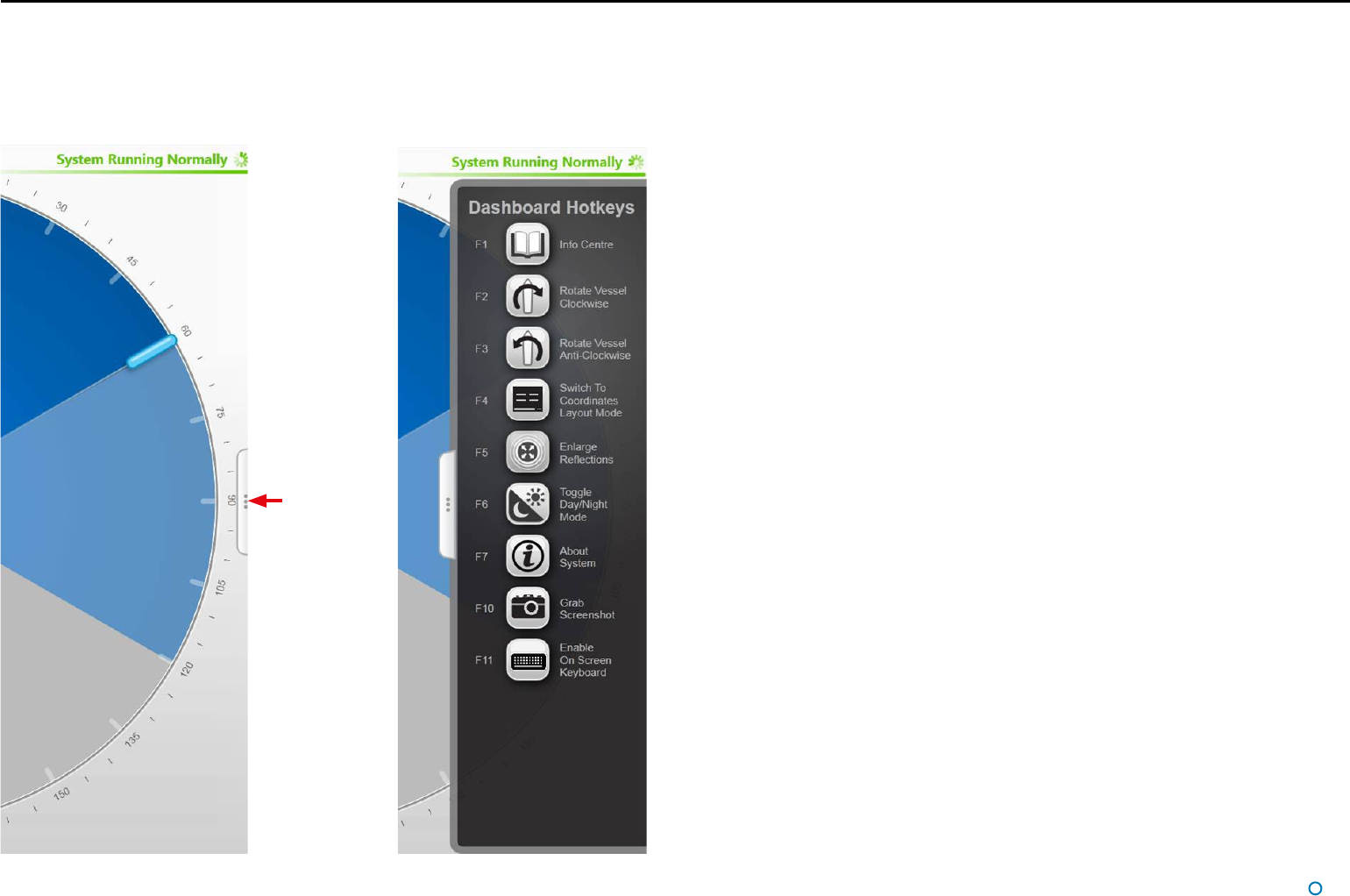
Hotkey Buttons
Selecting the Hotkeys tab on the right-hand side of the Bird's Eye View (BEV) activates the Dashboard Hotkeys menu.
Screen Contents (Continued)
The following keys - and the corresponding buttons on the Dashboard Hotkeys menu - act as
shortcuts to application functions.
F1 Help Menu.
F2 Rotates the vessel clockwise.
F3 Rotates the vessel counter-clockwise.
F4 Toggles between the default BEV Layout Mode and Coordinates Layout Mode.
F5 Toggles between enlarged and standard-sized representation of the remote station.
F6 Toggles between the day view and night view.
F7 Toggles between the About System pane and the full BEV or Coordinates display.
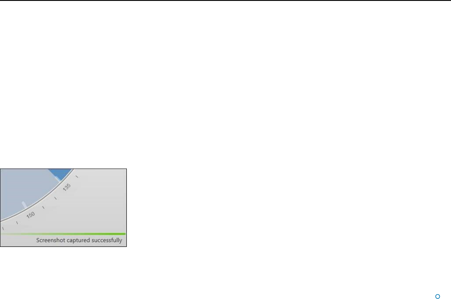
F10 Takes a snapshot of the screen and stores the image in the file desktop.bmp, at the
configured location for data logging (defined by the LogPath parameter in the config.ini
file, in the Artemis Dashboard installation folder).
F11 Enables or Disables the On Screen Keyboard function.
Esc When in operation confirmation mode, cancels the current operation request; in all
other modes, brings back the full BEV or Coordinates screen.
Return
When in operation confirmation mode, confirm the current operation request.
Hotkeys Tab
l 15
Screen Contents (Continued)
Menu Pane
The menu pane, located across the bottom of the Dashboard screen, is not always visible.
It appears when the Auto Search or Advanced buttons at the foot of the side bar are
pressed, which causes the main screen to contract upwards. Clicking the same button for
a second time causes the menu pane to disappear and the main screen to be restored to
full size.
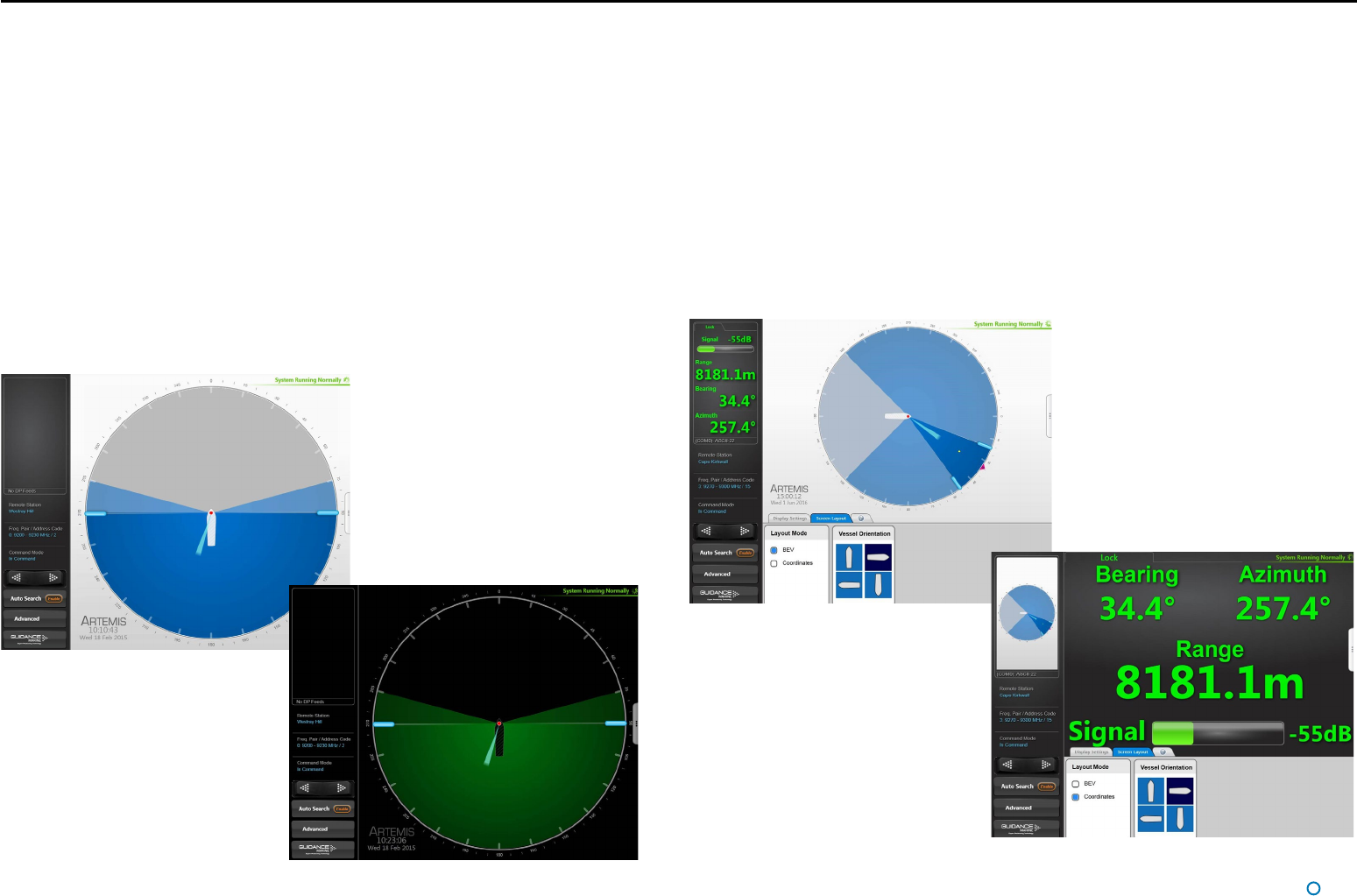
l 16
Display Options
Display View
To provide ample visibility during daytime operation and to limit glare during night shifts, the
Artemis Dashboard offers two display modes: Day View and Night View. In either mode the
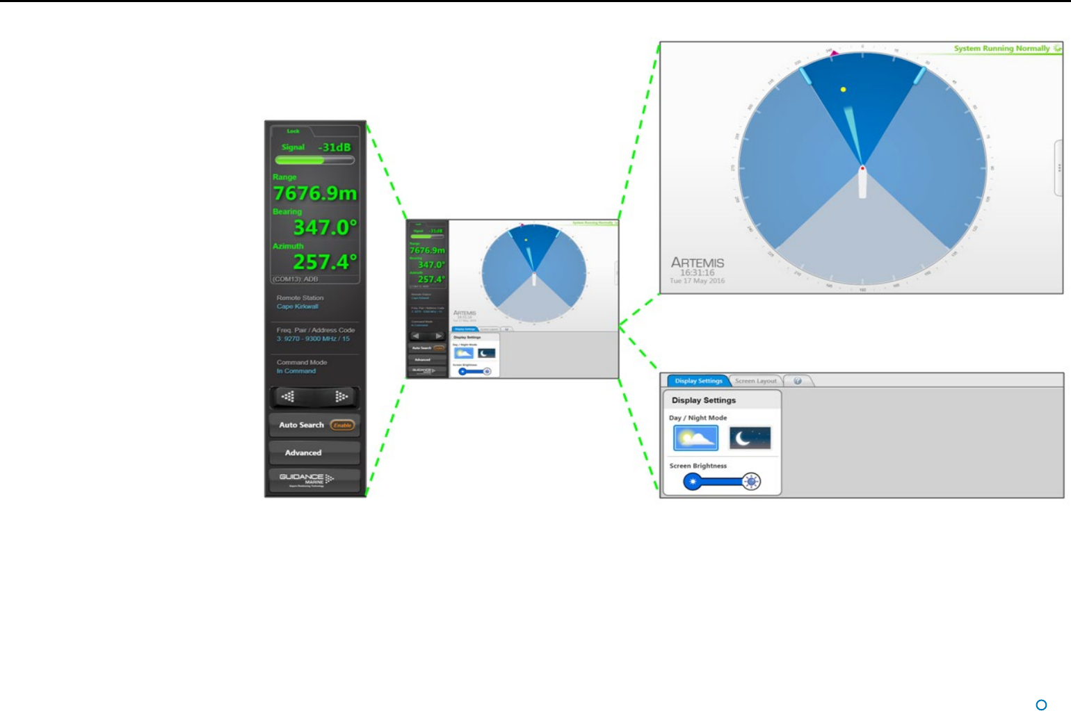
brightness can be further adjusted by the Screen Brightness control.
To Change the Day/Night View and Adjust Brightness:
1. If the Guidance Home Menu is open in the Side Bar, close it by clicking on the
Guidance button.
2. Navigate to Advanced > Display Options > Display Settings.
3. Click on the Day View or Night View symbol.
4. Click on the left side of the Screen Brightness control to dim the screen and on the
right to make it brighter.
5. Alternatively, use the keyboard shortcut F6 or the Day/Night Mode button in the
Dashboard Hotkeys menu to switch between Day View and Night View.
Screen Layout Mode
By default, the main area of the Dashboard screen contains the Bird’s Eye View (BEV) and
if the local and remote stations are locked, the positional coordinates are displayed in the
upper part of the side bar. However, it is possible to swap these around so that the main
area shows the coordinates in extra-large text and the side bar contains a miniature BEV.
To Select the Screen Layout Mode:
1. Navigate to Advanced > Display Options > Screen Layout.
2. Select BEV or Coordinates.
OR
Click on the upper part of the side bar to toggle between the two layout modes.
Example Day View
Example Night View
Screen Layout Mode = BEV
Screen Layout Mode = Coordinates
Hotkey Buttons
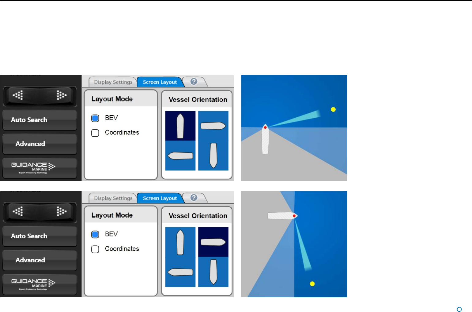
l 17
Display Options (Continued)
Vessel Orientation
The Artemis Dashboard supports four different arrangements of the Bird’s Eye View so that
the operator can choose the one which best represents his surroundings.
For instance, if the operator is facing forward when using the Dashboard, he would want
the bow of the vessel in the BEV to point upwards, so that a remote station located on the
starboard side of the vessel is shown on the right-hand side of the BEV.
To set Vessel Orientation:
1. Click on Advanced > Display Options > Screen Layout.
2. Click on the vessel outline that points in the required direction.
Alternatively, rotate the vessel clockwise by clicking F2 or the Rotate Vessel Clockwise
hotkey. Rotate anti-clockwise by clicking F3 or the Rotate Vessel Anti-Clockwise hotkey.
Hotkey Buttons

l 18
In order for the Artemis system to output positional data to a vessel’s DP system, the local
station needs to be tracking a remote station. This section explains how to achieve this.
It contains the following pages:
• Tracking Overview section on page 19
• Selecting a Remote Station section on page 20
• Adjusting the Scan Sector section on page 21
• Tracking Information Quality section on page 22
• DP Feeds section on page 23
Basic Operation
l 19
Tracking Overview
When an Artemis-equipped vessel moves within operating range of a remote station, the
two stations will lock on to each other if the following conditions are met:
• The correct remote station has been selected within the vessel’s Artemis Control Software
(see Selecting a Remote Station on page 20).
• The radar beams from both stations are illuminating the other.
In order to fulfil the second condition, the scan sectors of each station should be set up to
include the direction in which the other is located. In the case of a fixed station mounted
on a rig or on land, it should already be configured to search in the directions from which
vessels normally approach. For the mobile station on board a vessel, it may be necessary
to widen the scan sector in order to find the fixed station (see Adjusting the Scan Sector
on page 21).
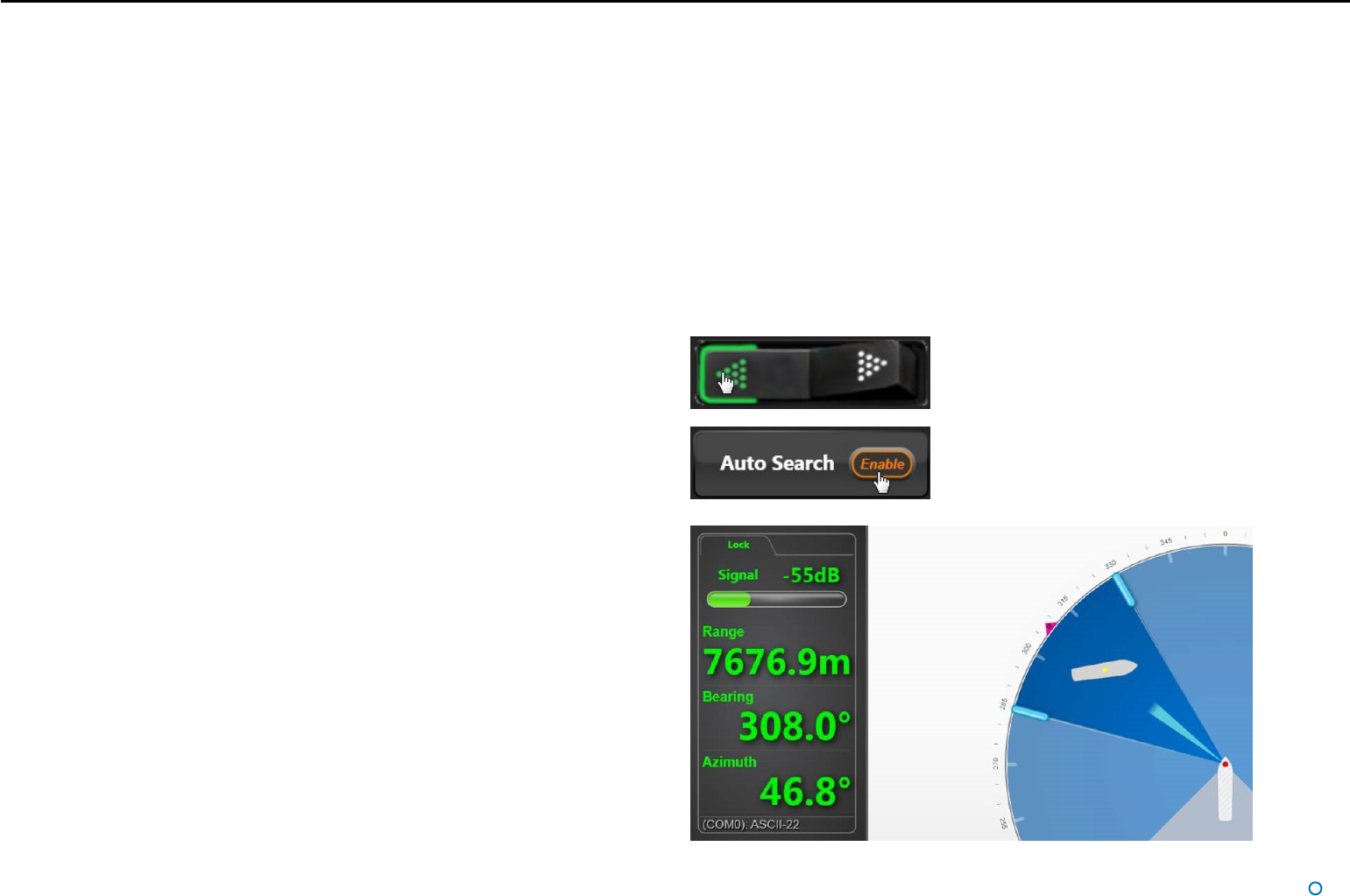
In order to locate the remote station within the scan sector, the beam direction can be
altered either manually or automatically:
• Rotate the beam manually using the rocker switch on the side bar. Click the left-hand
side of the switch to move the beam in a counter-clockwise direction by a small amount.
Similarly, click the right-hand side to move in a clockwise direction. Click repeatedly or
hold the switch down to move further.
• Click the Enable button embedded within the Auto Search button in order to search
automatically. This causes the beam to sweep from side to side across the scan sector
until it locks onto the remote station, or until Auto Search is disabled.
When the stations are locked, the remote station is represented on the BEV by a yellow
dot, the size of which varies with the strength of the received signal. If the remote station
has a structure type of Floating, an outline of its vessel is shown (with its bow aligned to 0°
azimuth).
Once a lock has been achieved, DP feed messages are output via the configured DP
channel(s). The position of the remote station and its signal strength are displayed at the
top of the side bar (or on the main screen if Coordinates Layout Mode has been selected).
(see Tracking Information Quality on page 22).
Leaving Auto Search enabled on the local station causes the beam to search for the remote
station if it is lost (e.g. due to another vessel passing across the line of sight).
If the local vessel is station keeping, or is moving along a trajectory such that the bearing
of the remote station remains about the same, you may wish to narrow the scan sector
around the remote station. The advantage of this is to reduce the time required to find the
remote station again after losing it.
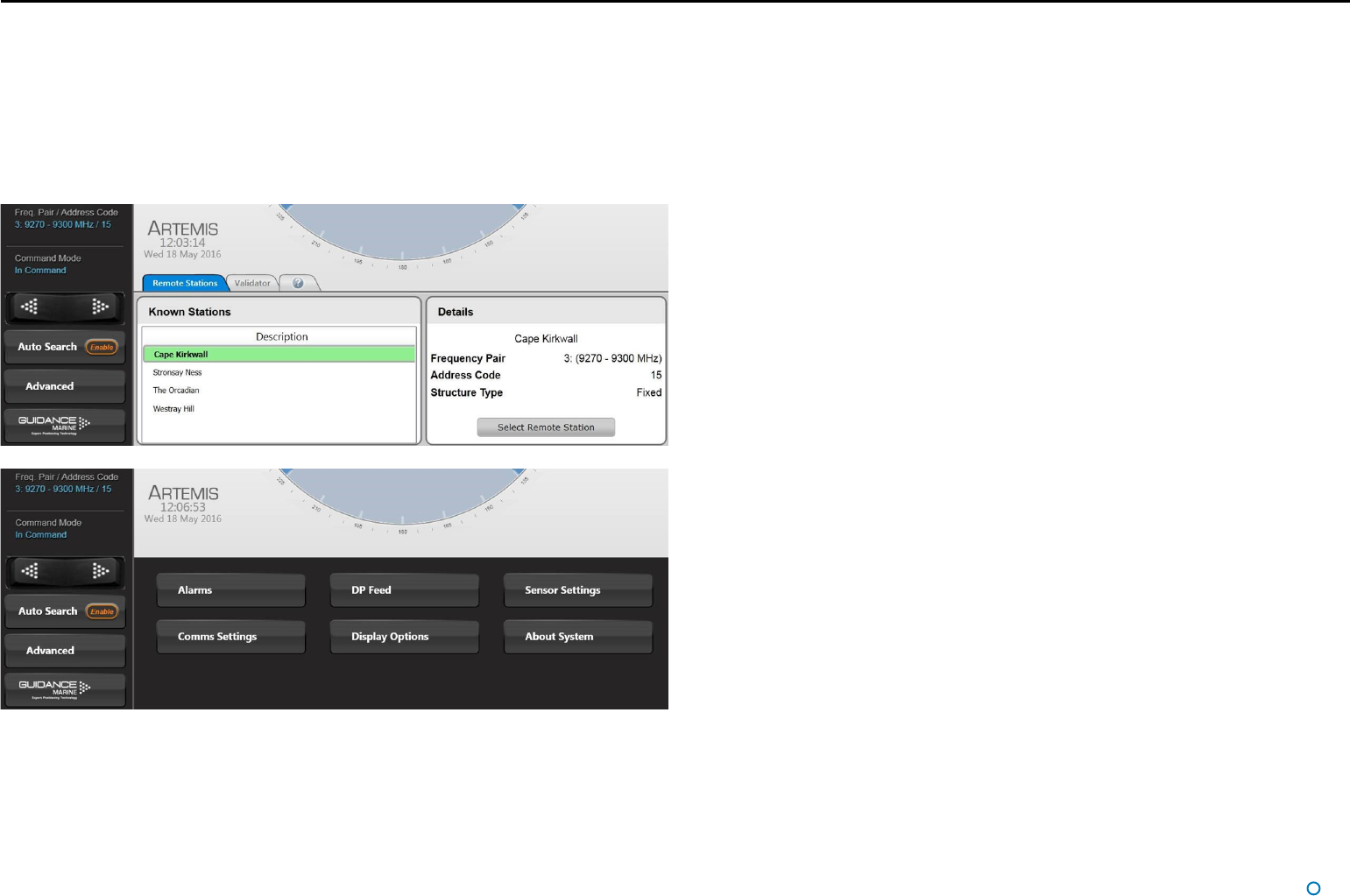
l 20
Selecting a Remote Station
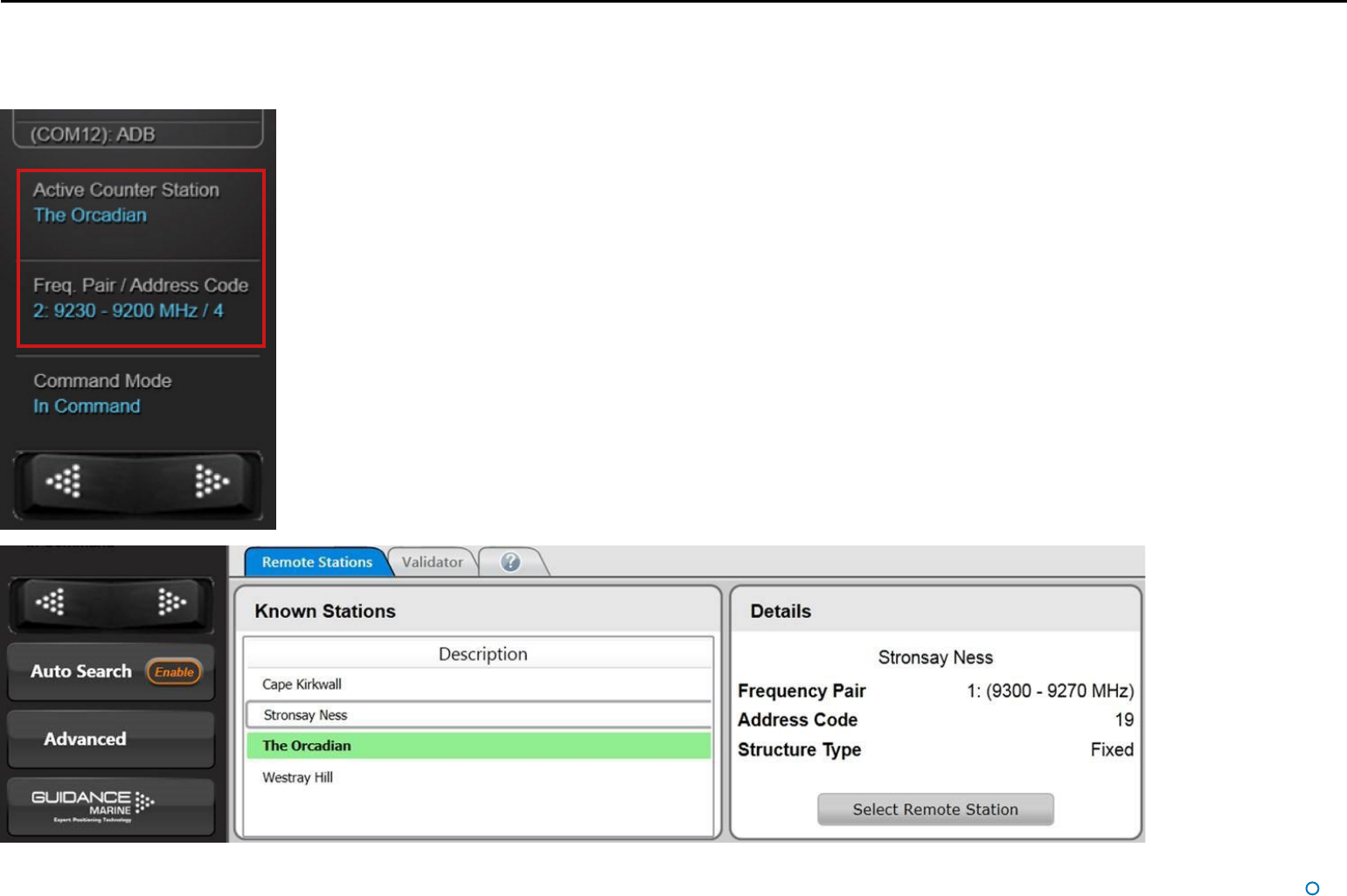
Although the local Artemis station tracks only one remote station at a time, it can be configured with a list of multiple prospective stations (see Artemis Mk6 Installer’s Guide). The side bar
of the Dashboard screen displays the description of the currently selected remote station, its address code and the frequency pair used when the local station communicates with it.
To Select a Different Remote Station:
1. Ensure that the Dashboard is In Command (if not, click on the Guidance button then Take Command).
2. Click on the Auto Search button on the side bar.
This causes the Remote Stations menu pane to open. The description of the currently selected remote station has a green background.
3. Select a different remote station by clicking on its description in the list.
The details of the selected remote station are displayed in the right-hand side of the pane.
4. Click on Select Remote Station.
The description of the newly selected remote station now has a green background.
l 21
Adjusting the Scan Sector
The Dashboard operator can alter the size of the scan sector, the dark blue area across
which the antenna sweeps when auto-searching.
A wider scan sector may be required in order to find a remote station. Once the stations are
locked and if its bearing is not expected to change much, a narrower scan sector may be
required in order to quickly re-establish the lock should it be interrupted.
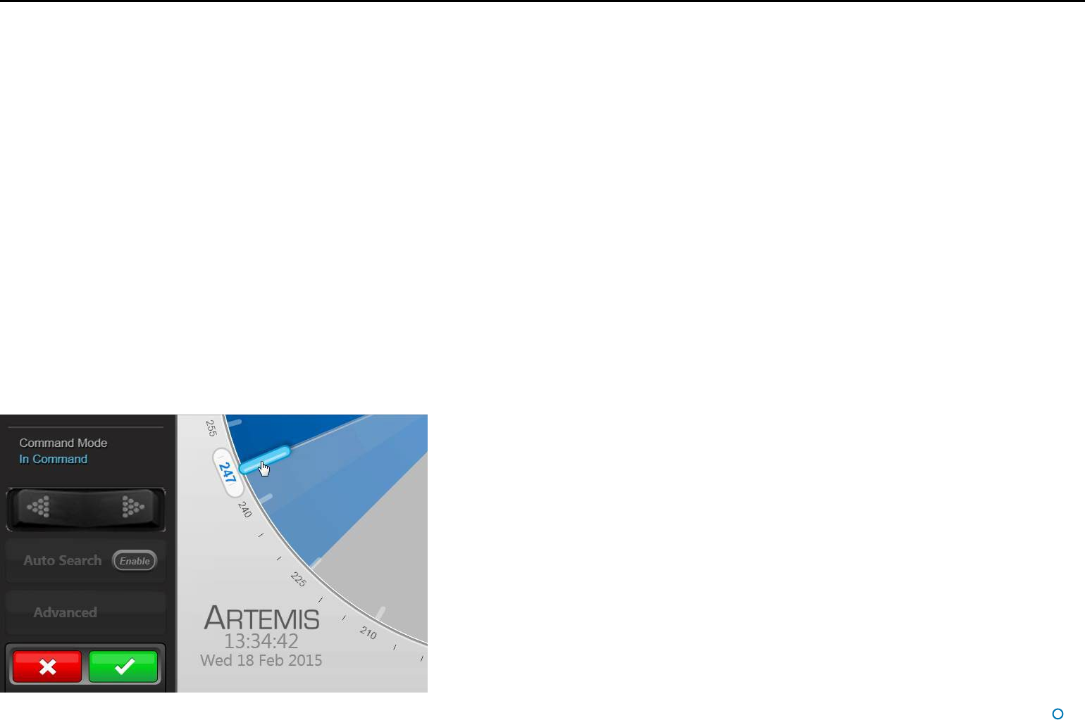
To Adjust the Scan Sector:
1. Ensure that the Dashboard is In Command mode (if not, click on the Guidance button
then Take Command).
In Command mode there are handles along each radial edge of the scan sector.
2. Click one of the scan sector handles on the BEV and, holding down the left mouse
button, drag to the required position. Alternatively – on a touchscreen – touch and drag.
As the handle is moved, its current position (in degrees clockwise from the vessel bow) is
displayed in blue numerals outside the perimeter of the circle.
This will cause the Apply and Cancel buttons to appear at the foot of the side bar.
3. If required, drag the second handle in the same way.
4. Click on the Apply (tick) button to confirm.
Note that the scan sector cannot be narrower than 5°, nor can it extend into the dark grey
area of the BEV (defined by the End Limits - see Artemis Mk6 Installer’s Guide).
l 22
Tracking Information Quality
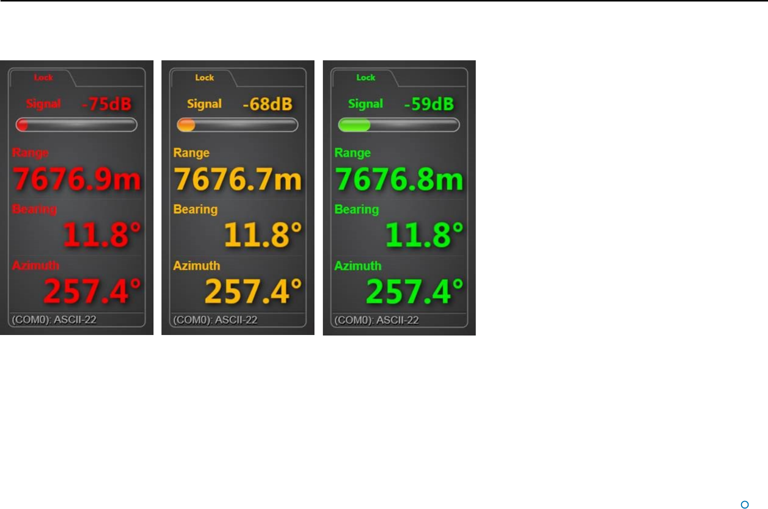
When the system is locked, the coordinates of the remote station and the strength of the signal received from it are displayed at the top of the side bar (or on the main screen if
Coordinates Layout Mode has been selected). This data is colour coded:
The colours denote signal strength:
Red: -80dB to -72dB
Amber: -71dB to -65dB
Green: -64dB to 0dB
l 23
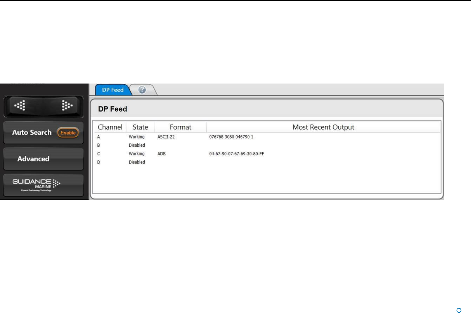
DP Feeds
Up to four ports of the Artemis Control PC can be configured as DP Feed channels, in order to output positional data to the vessel’s DP system (see Artemis Mk6 Installer’s Guide).
The state of each channel, its data format and the most recent data output can be viewed on the Dashboard.
To View DP Feed Details:
1. Click on the Advanced button on the side bar.
2. Click on the DP Feeds button on the menu pane.
l 24
An Artemis system can include multiple PCs, each running the Dashboard program. At any
given time all of the Dashboards may be in Monitoring mode, or else one Dashboard – and
only one – may be in command mode.
This section explains the difference between the two modes and how to switch between
them. It contains the following pages:
• Artemis Dashboard – In Command Mode section on page 25
• Artemis Dashboard - Monitoring Mode section on page 26
Multi-Dashboard Artemis Systems
l 25
Artemis Dashboard – In Command Mode
It is necessary to run a Dashboard in command mode in order to use its system control
functions (e.g. adjusting the scan sector or activating a different remote station). Any
changes made in these areas will be evident on the screens of the monitoring Dashboards.
On the other hand, display options such as screen brightness or vessel orientation can be
set differently on each individual Dashboard, whether it is in command or monitoring.
When the Dashboard in command is used to suspend the local station, a message
will appear on the screens of the monitoring Dashboards indicating that the system is
suspended.
In this state, clicking the Resume button on any Dashboard will automatically put it in
command mode.
If no Dashboard within the system is in command, the next Dashboard to be opened will
default to In Command mode. Subsequently, new Dashboards will default to Monitoring
mode.
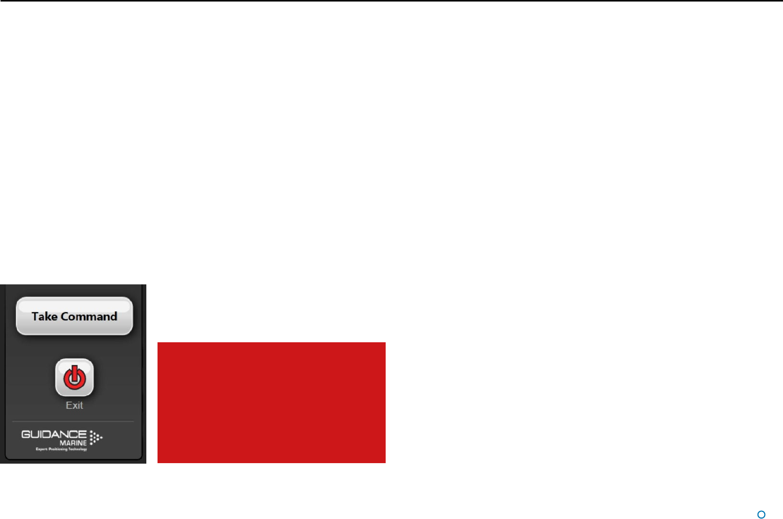
To switch a Dashboard from Monitoring mode to In Command:
1. Click the Guidance button at the foot of the side bar.
2. Click the Take Command button.
If there was already another Dashboard in command mode, it will automatically switch to
Monitoring mode when this Dashboard takes command.
A Dashboard cannot directly take command
away from a Service Interface application.
If a Service Interface is currently in
command, the Dashboard’s Take Command
button will be disabled and dark grey in
appearance.
In order to enable it, click on the Relinquish
Command button on the Service Interface.
Vessel Orientation
l 26
Artemis Dashboard - Monitoring Mode
When the Dashboard is running in Monitoring mode the controls relating to the Dashboard
itself will be active, but those relating to other parts of the system will be disabled.
Monitoring Dashboards display the same positional information as the Dashboard in
command, but cannot search for a remote station, activate a different one or suspend the
local station.
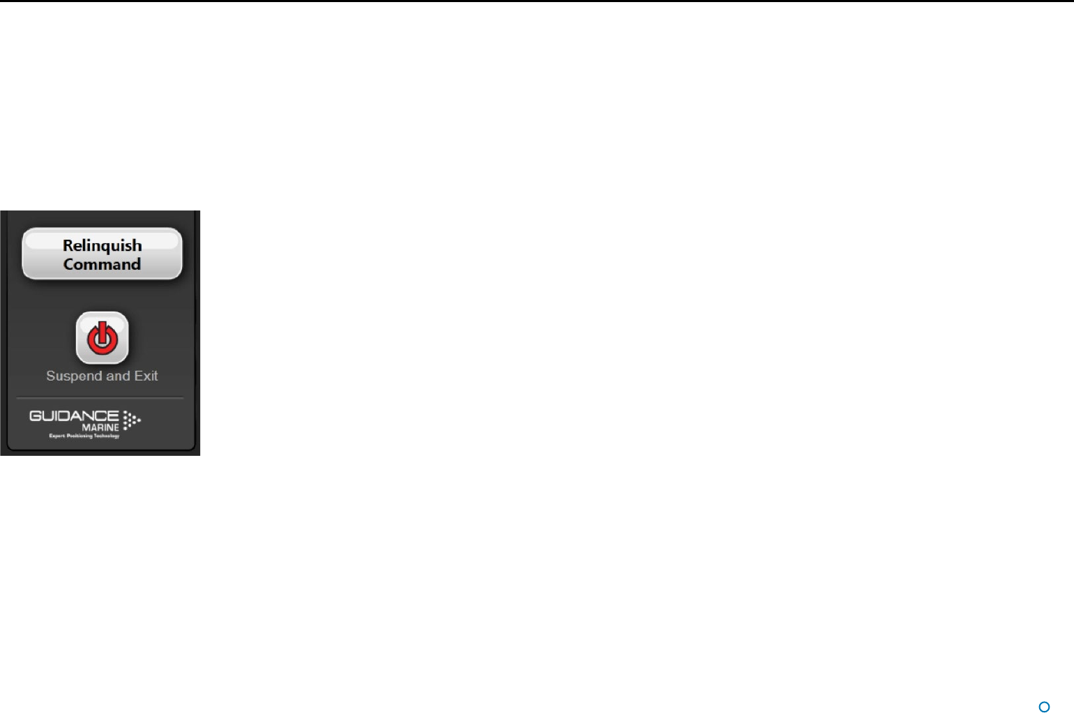
To switch a Dashboard from In Command mode to Monitoring:
1. Click the Guidance button at the foot of the side bar.
2. Click the Relinquish Command button.
l 27
This section contains the following pages:
• Serial Numbers and Software Versions on page 28
• Network Communications Settings on page 29
• Sensor Settings on page 30
• Using the On-Screen Keyboard on page 31
• Working with Alarms on page 32
• International Standards Compliance on page 34
• System Specications on page 35
Support Information
l 28
Serial Numbers and Software Version Numbers are used to identify the hardware
configuration and product revision of the Artemis system. They will be requested by
Guidance Marine in the event of a support call to the company.
Serial Numbers and Software Versions
Product Labels
The Part Number and Serial Number for an Antenna Unit can be found on the product label
fixed onto the base.
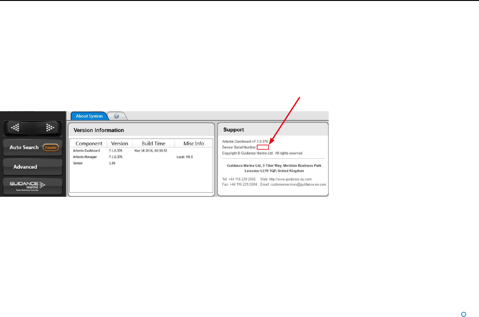
Software Version Information
The About System pane provides version information for the Dashboard and Manager
applications, and the software within the Antenna Unit (sensor).
Sensor Serial Number
l 29
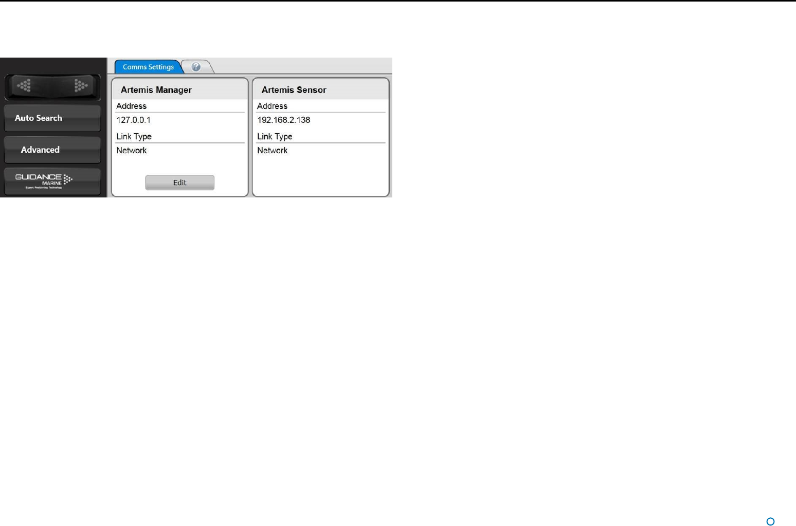
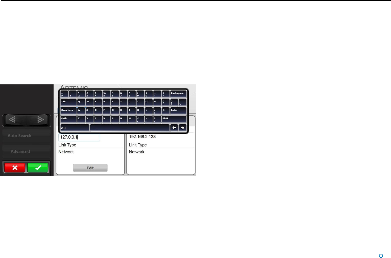
The Comms Settings menu pane displays the configuration of communications between
the Dashboard and Manager and between the Manager and Sensor (local station).
Network Communications Settings
To Change the IP Address of the Artemis Manager:
1. Ensure that the Dashboard is not in communication with the manager. If necessary, click
on the following buttons:
i) Guidance
ii) Relinquish Command
iii) Disconnect
2. Navigate to Advanced > Comms Settings.
3. Click on the Edit button within the Artemis Manager panel.
4. Amend the IP Address.
5. Click on the Apply button to confirm.
To Change the Comms Settings for the Artemis Sensor:
Use the Service Interface (see the Artemis Mk6 Installer’s Guide); the Artemis Sensor panel
on the Comms Settings pane of the Dashboard is for information only.
l 30
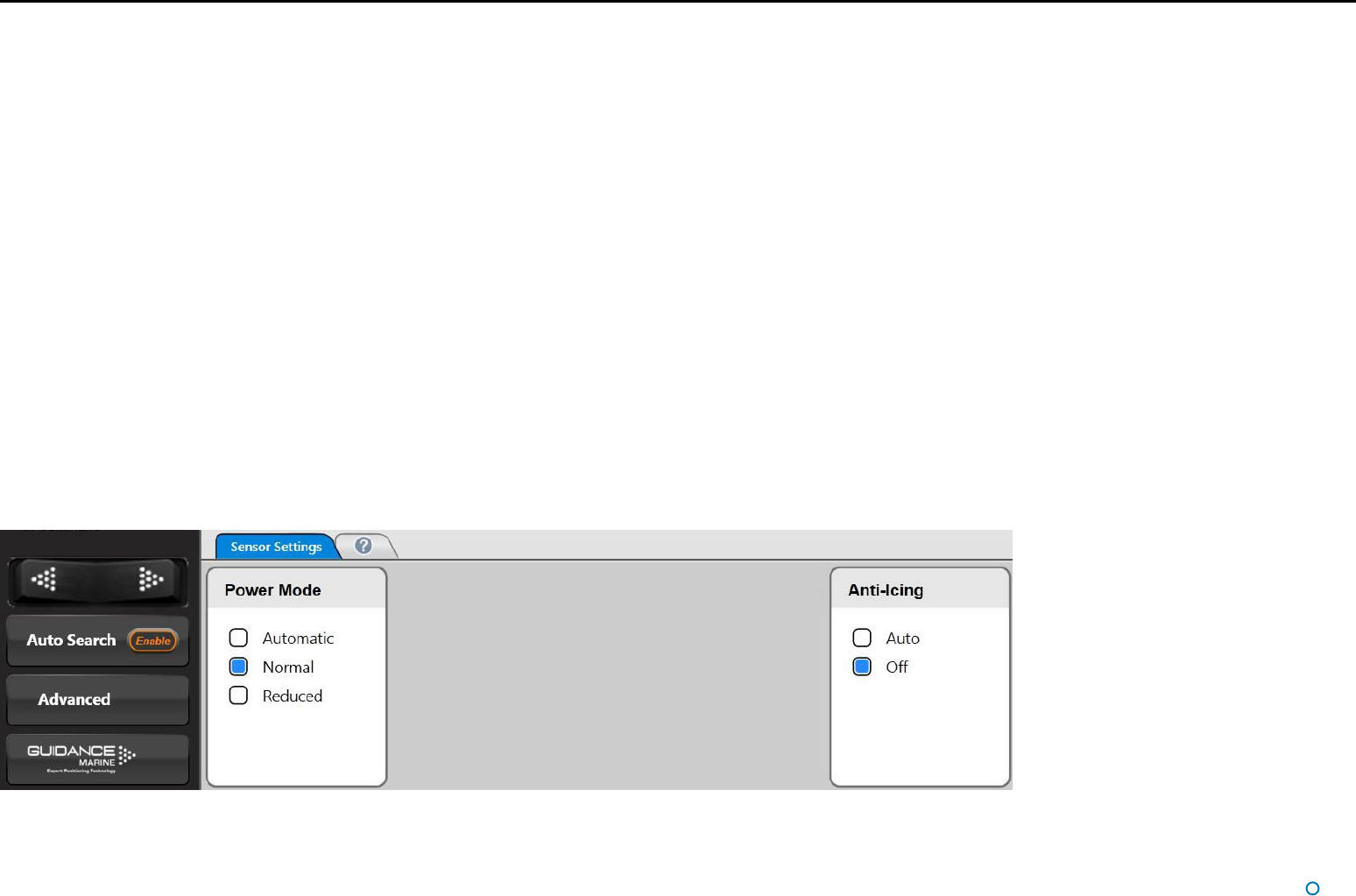
The following two functions of the local Artemis station can be controlled from the
Dashboard:
Sensor Settings
Power Mode
Normal power mode is suitable when the range between the local and remote stations
is 200m or more.
Reduced power mode is suitable for ranges less than 200m.
Automatic causes the power mode to be automatically switched between Normal and
Reduced depending on the current range between the stations.
Anti-Icing
When this is set to Auto and the temperature falls towards freezing point, the heating
inside the Artemis antenna will automatically be switched on.
To Change the Sensor Settings:
1. Click on the Advanced button on the side bar.
2. Click on the Sensor Settings button on the menu pane.
3. Amend the Power Mode and/or Anti-Icing settings.
4. Click on the Apply button.
l 31
Using the On-Screen Keyboard
The Artemis Dashboard provides an On-Screen Keyboard (OSK), which allows ttext to be
input using a mouse, trackball or touch screen.
To enable the on-screen keyboard
The OSK will already be enabled if you selected this option during installation of the
Dashboard. Otherwise, the OSK can be enabled and disabled by clicking F11 or by clicking
Enable On Screen Keyboard/Disable On Screen Keyboard on the Dashboard Hotkeys
menu.
To use the on-screen keyboard
Simply click on any text entry field and the OSK will pop-up ready for use:
Click on the necessary keys on the on-screen keyboard using your mouse or by tapping the
touch screen.
Hotkey Buttons
l 32
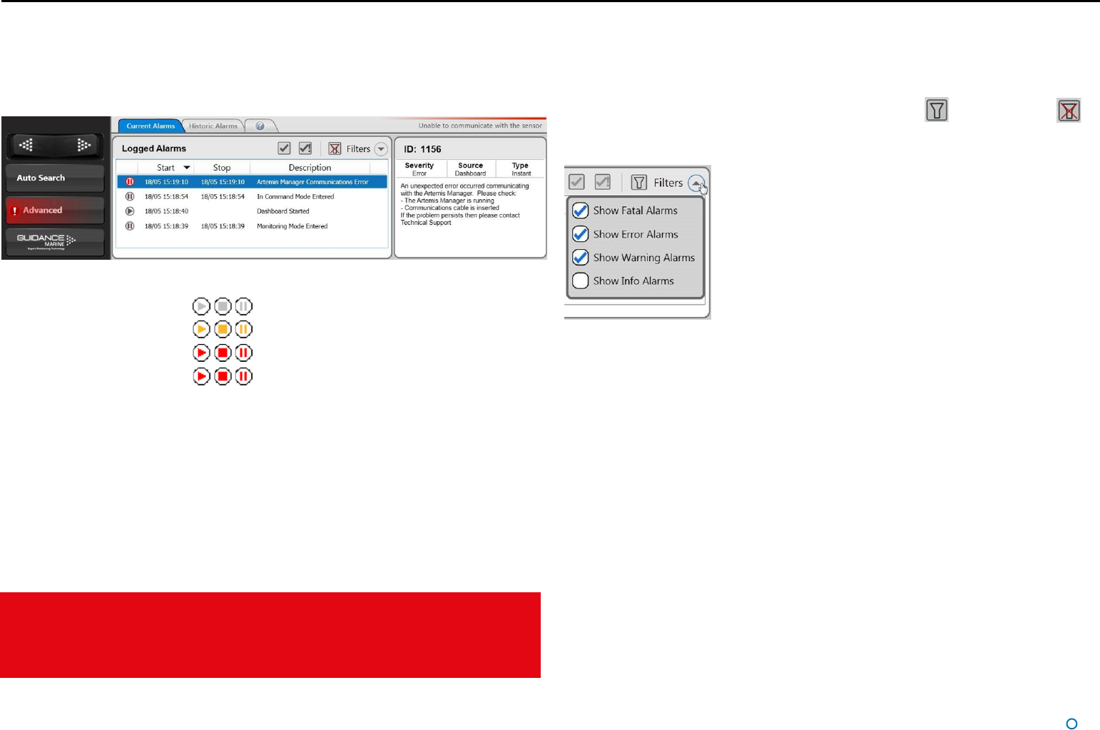
Working with Alarms
During operation, the Artemis system produces an audit trail of event messages. These
range in increasing order of severity from: Information, Warning, and Error to Fatal. As
these alarms are raised, the Dashboard lists them within the Alarms pane. Click on any
alarm to display details about it in the right-hand section of the Alarm pane:
When a Fatal alarm occurs, communications with the sensor are disabled.
In order to return to normal operation, ensure that the fault condition has been
cleared, close the Dashboard and re-open. If communications are not re-established,
power the sensor off, wait for 20 seconds then power back on.
The severity and current state of an alarm are reflected in its colour and shape:
• Information—grey symbols
• Warning—orange symbols
• Error—red symbols
• Fatal—red symbols
The arrowhead symbol indicates that an alarm condition is persisting; an alarm in this state
will show a Start time but not a Stop time.
The square symbol means that the alarm condition no longer exists, therefore the alarm will
show both Start and Stop times.
The pause symbol indicates an instantaneous alarm. In this case, the Start and Stop times
are identical.
When an Error or Fatal alarm is raised, the Alarms pane is opened automatically and its
Side Bar button is shaded red as in the example above. If the pane is closed and re-
opened, the Side Bar button returns to its normal light grey shading.
Filtering Alarms
A filter is available to suppress the display of particular alarm types. By default, the filter is
activated and causes information messages to be hidden.
Click on the Alarm Filter button to toggle between activated and de-activated .
Click on the Filter Selection button to choose which types of alarm are to be filtered out:
A tick means that alarms of the corresponding severity are always viewable in the alarms
list. No tick means that alarms of that severity are hidden when the filter is activated.
l 33
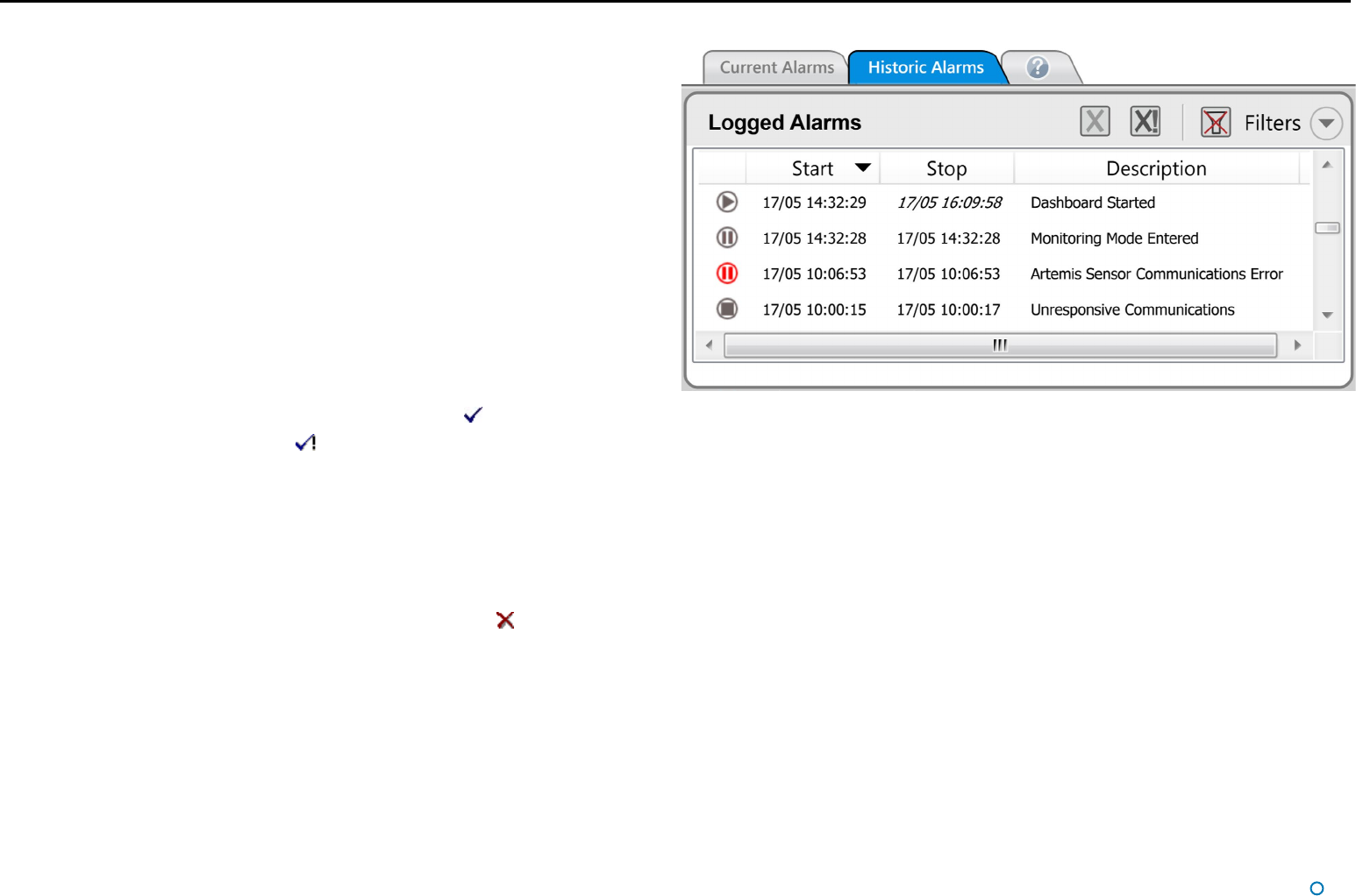
Using the Current and Historic Alarms Tabs
There are two tabs on the Alarms pane, each containing a list of alarms:
• The Current Alarms tab displays new alarms (raised since the Dashboard was last
opened).
• The Historic Alarms tab displays alarms that have been cleared from the Current
Alarms tab.
Current alarms are automatically transferred when the Dashboard is closed or when the
maximum number of Current Alarms has been reached.
Items on the Current Alarms tab cannot be deleted, they may only be moved to the
Historic Alarms tab. Only items on the Historic Alarms tab can be permanently deleted.
To accept alarms on the Current Alarms Tab
1. Click on Advanced > Alarms and ensure that the Current Alarms tab is in focus.
2. Select the alarms that you wish to move into the Historic list:
To accept one alarm—Click on the alarm and click on the button.
To accept all alarms—Click on the button.
3. Click Apply to move these alarm(s) onto the Historic Alarms tab.
Working with Alarms (Continued)
!This will not apply to alarms that have been hidden by the lter mechanism.
To clear alarms on the Historic Alarms tab
1. Click on Advanced > Alarms and ensure that the Historic Alarms tab is in focus.
2. Select the alarms to delete:
To delete one alarm – click on the alarm entry and then on the button.
To delete all alarms – click on the X! button.
3. Click Apply to confirm.
!This will not apply to alarms that have been hidden by the lter mechanism.

l 34
International Standards Compliance
Artemis Mk6 Equipment
European Union
The equipment is permitted to be used in all EU member states
without the need for a specific administrative licence.
Artemis Mk6 equipment meets the requirements of Directive 2004/108/EC and complies
with EN 60945:2002.
Norway
Note that in Norwegian waters a maritime radio licence is required for
the use of the Artemis Mk6 system.
Please contact Telenor Maritime Radio to obtain a licence:
Telenor Maritime Radio
Radio Licensing Department
N-1331 FORNEBU
NORWAY
Tel: +47 22 77 43 50
Fax: +47 22 42 70 72
Web: www.maritimradio.no
USA
Authorisation by the Federal Communications Commission for the use of Artemis Mk6
equipment in the United States of America is pending. FCC ID: VYMARTEMIS.
l 35
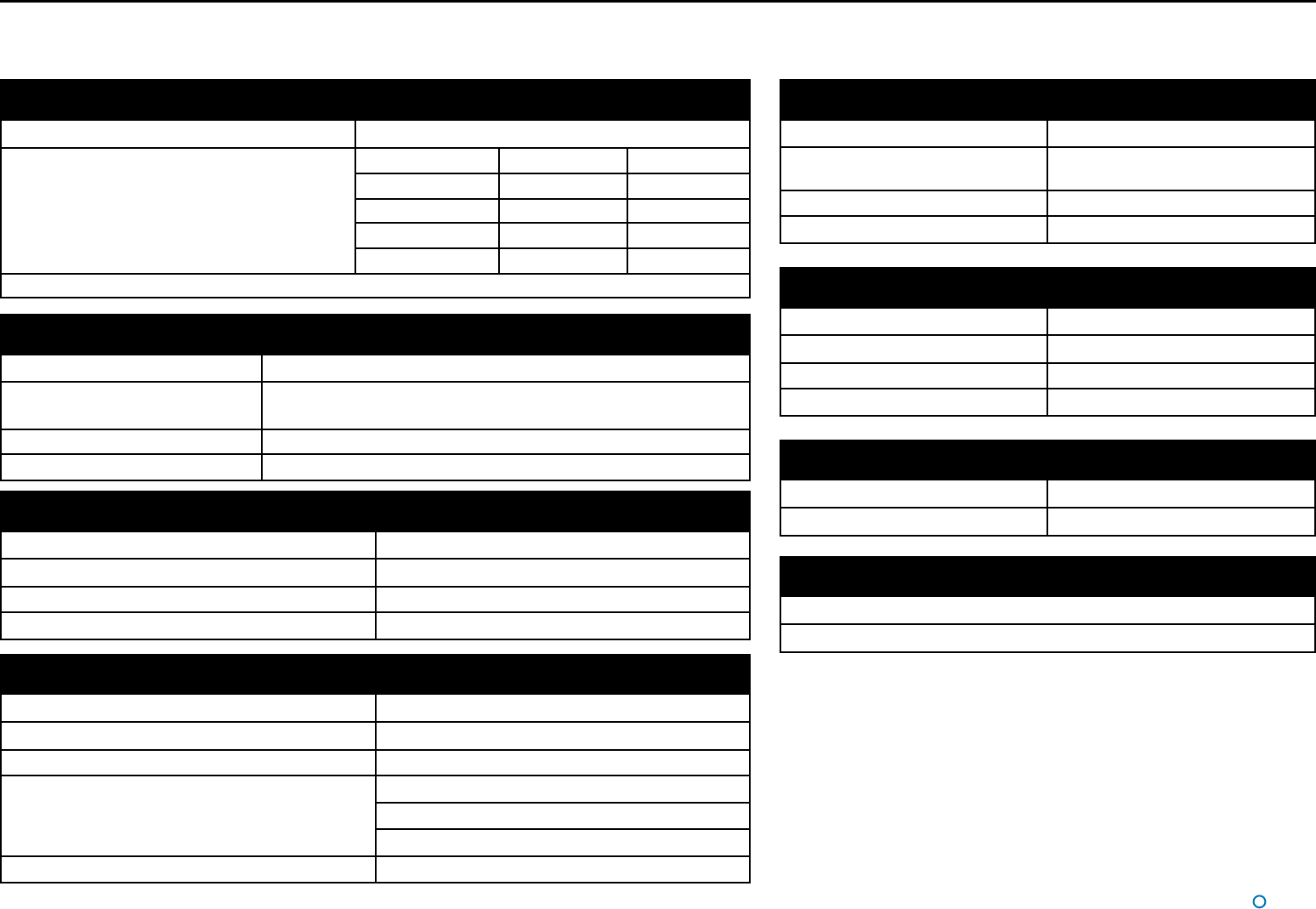
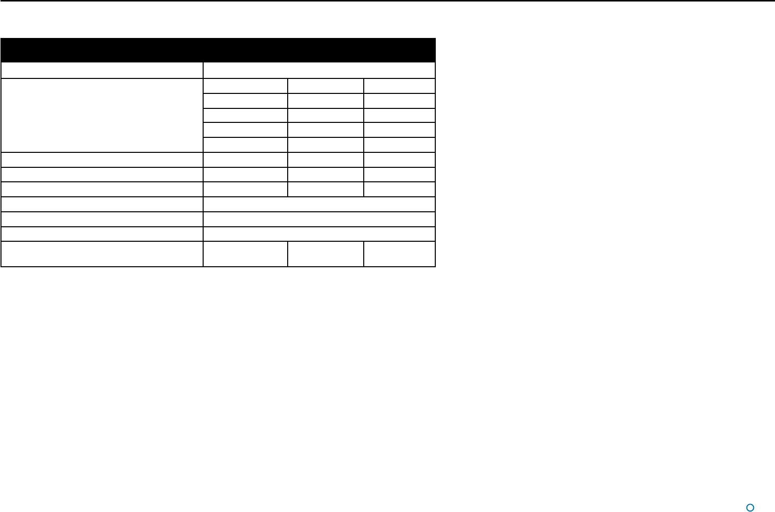
Frequency
Frequency band 9200 - 9300 MHz
Four xed, user-selectable frequency pairs Pair Mobile Station Fixed Station
0 9200 MHz 9230 MHz
1 9300 MHz 9270 MHz
2 9230 MHz 9200 MHz
3 9270 MHz 9300 MHz
*Automatic frequency control on Mobile Station
System Specifications
Azimuth Measurement
Range 360°
Display resolutions 0.1 on Dashboard
0.01 on Artemis Service Interface
Data update rate 0.25s
Overall absolute accuracy 0.02° standard deviation
Connections
Power supply cable 3 x 1.5mm² with screen; outside diameter 7 – 13mm
Ethernet cable STP (Shielded Twisted Pair) outside diameter 4.5 – 10mm; connector
RJ45 units with an EOR board have a 10MB connection
Keypad cable STP (Shielded Twisted Pair) outside diameter 4.5 – 10mm
Overall absolute accuracy 0.02° standard deviation
Dimensions and Weights
Antenna 1248 x 206 x 176.5mm/approx. 5kg
Antenna Unit Ø 366 x 500mm/32.8kg
Re-usable container for Antenna Unit 520 x 650 x 590mm (l x w x h)
Re-usable container for Antenna 1320 x 250 x 220mm (l x w x h)
Distance Measurement
Range 10m – 10,000m
Display resolutions 0.1m
Data update rate 0.25s
Overall absolute accuracy 1m standard deviation
Power Requirements
Supply voltage 220-240 VAC, 50-60 Hz
Power consumption 75 W
Environmental Conditions
Temperature operating range -20 °C to +55 °C
Storage temperature range -40 °C to +70 °C
Weather protection antenna and Antenna Unit IP66 (exposed conditions)
Safety Machinery Directive 2006/42/EC
EMC Directive 2004/108/EC
Low Voltage Directive (LVD) 2006/95/EC
Resistance to corrosion Suitable for salt water environment
Antenna Unit (Mobile and Fixed Station)
Supported DP Telegram Formats
ADB, BCD, ASCII 16, 17, 22
Custom strings may be available on request
l 36
System Specifications (Continued)
General Specifications
Frequency band 9200 - 9300 MHz
Four xed, user-selectable frequency pairs Pair Mobile Station Fixed Station
0 9200 MHz 9230 MHz
1 9300 MHz 9270 MHz
2 9230 MHz 9200 MHz
3 9270 MHz 9300 MHz
Radiated power 100 mW max 100 mW max 100 mW max
Polarisation Vertical Vertical Vertical
Range
With omni directional antenna type AT-120 10m – 2,500m
With semi omni directional antenna type AT-010 10m – 5,000m
With horn antenna type ATH-010A 15m – 1,000m
Supply voltage 220-240 VAC,
50-60 Hz
220-240 VAC,
50-60 Hz
220-240 VAC,
50-60 Hz
Beacon
Guidance Marine reserves the right to alter or amend this published specification without notice.

l 37
R
Radial Markers 11
Remote Station 11, 19, 20
Resume Button 9, 25
S
Scan Sector 11, 21
Screen Layout 16
Sensor Settings 30
Serial Number 28
Service Interface 6, 25, 29
Shut Down 9
Side Bar 9, 10, 13
Signal Strength 22
Software Version 28
Start Up 9
Suspend and Exit Button 9
Suspend Button 9
System Overview 6, 7
System Specication 35
System Status 11, 12
T
Tracking 7, 9, 19, 22
V
Vessel Orientation 17, 25
Vessel Outline 11
A
Alarms 32
Antenna Units 6
Anti-Icing 30
B
Beacon Unit 7, 36
BEV Layout Mode 16
Bird’s Eye View 10, 11, 16, 17
C
Clearing Alarms 33
Control Software 6
Coordinates Layout Mode 16
Current Alarms 33
D
Dashboard 6
Day/Night View 16
Disconnect Button 9
Display Settings 16
DP Feeds 23
E
Exit Button 9
Explosion-Proof Units 6
F
Filtering Alarms 32
G
Guidance Button 9, 13, 16, 20, 21, 25, 26
Guidance Home Menu 9, 13, 16
H
Historic Alarms 33
Hotkey Buttons 11, 14, 16, 17, 31
I
In Command Mode 25
International Standards Compliance 34
M
Main Screen 10, 11
Manager 6
Menu Pane 10, 15
Monitoring Mode 26
N
Network Communications 29
Night View 16
O
On-Screen Keyboard 31
Operating Panel 6
Overview
System 6, 7
P
Power Mode 30
Index