Guidance Marine RADASCAN RADASCAN User Manual Radascan Operators Manual
Guidance Navigation Ltd. RADASCAN Radascan Operators Manual
UserManual.wiki
>
Guidance Marine
>
RADASCAN User Manual
>
USERS MANUAL
Contents
1.
USERS MANUAL
2.
INSTALLATION MANUAL
USERS MANUAL
Navigation menu
Upload a User Manual
Namespaces
Wiki Guide
HTML
PDF
Info
Views
User Manual
Discussion / Help
Navigation
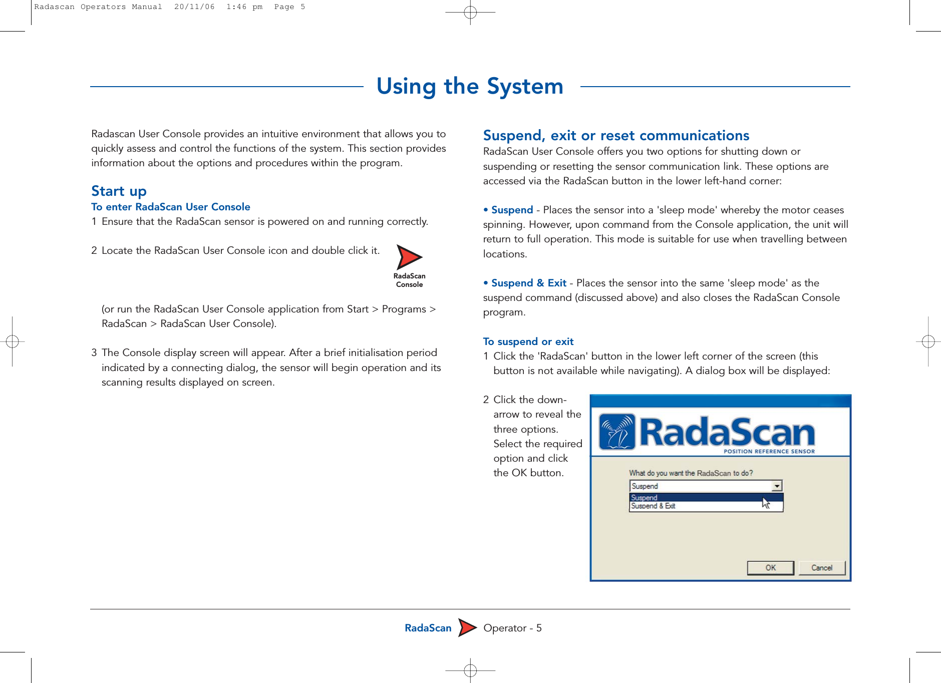

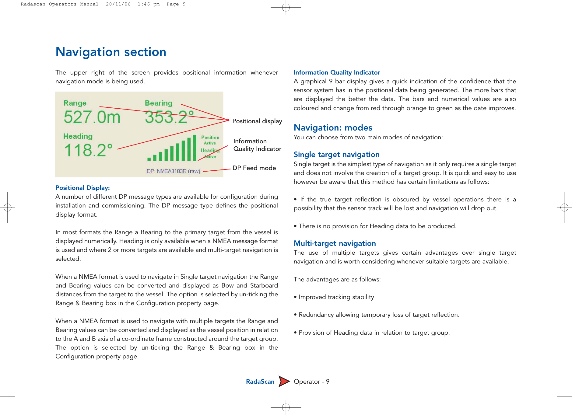
![RadaScan Operator - 10Navigation: single targetTo start single target navigation1 Click the button to reveal a pop-up list of navigation options.2 Select [Single Target] 3 In the subsequent dialog, click 'OK' to confirm your selection.4 Click the cursor on one of the target reflections shownon the sensor display. After a short delay, the navigation data will be determined and displayed. Note that only 'Range and Bearing' or 'Bow and Starboard' values will beshown as single target/prism modes cannot provide heading information.To end single target navigation1 Click the button.2 In the subsequent dialog, click 'OK' to confirm your action. The readouts in the navigation section will become inactive and turn grey. Theviewed targets will remain shown on the sensor display.Navigation: multi-targetTo start multi-target navigationThe Multi-target navigation option only becomes available when Radascanidentifies 2 or more authentic Radascan targets1 Click the button to reveal a pop-up list of navigation options. 2 Select [Multi-Target] 3 In the subsequent dialog, click 'OK' to confirm your selection. RadaScan will automatically identify the available targets and after a shortdelay will start to navigate against them.To end multi-target navigation1 Click the button.2 In the subsequent dialog, click 'OK' to confirm your action. The readouts in the navigation section will become inactive and turn grey.The viewed targets will remain shown on the sensor displayInformation quality indicatorWhen beginning either single or multi-target navigation, the readouts in thenavigation section of the screen (top right corner) will initially turn red (toindicate that the positional information received is not yet sufficient). TheRadaScan system will improve upon its positional information and as qualityincreases, the readouts will change from red to amber and then to green.Additionally, the information quality indicator bar graph will show moresimilarly coloured bars. Radascan Operators Manual 20/11/06 1:46 pm Page 10](https://usermanual.wiki/Guidance-Marine/RADASCAN.USERS-MANUAL/User-Guide-917507-Page-12.png)
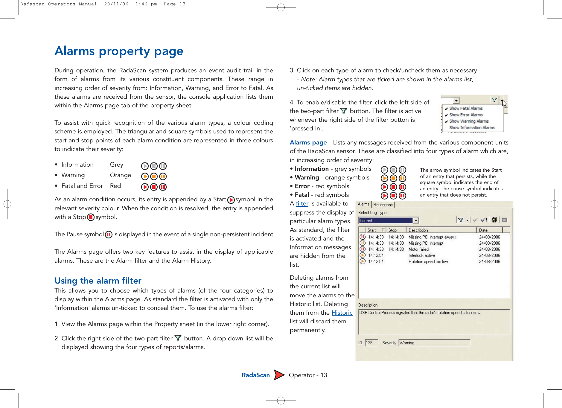
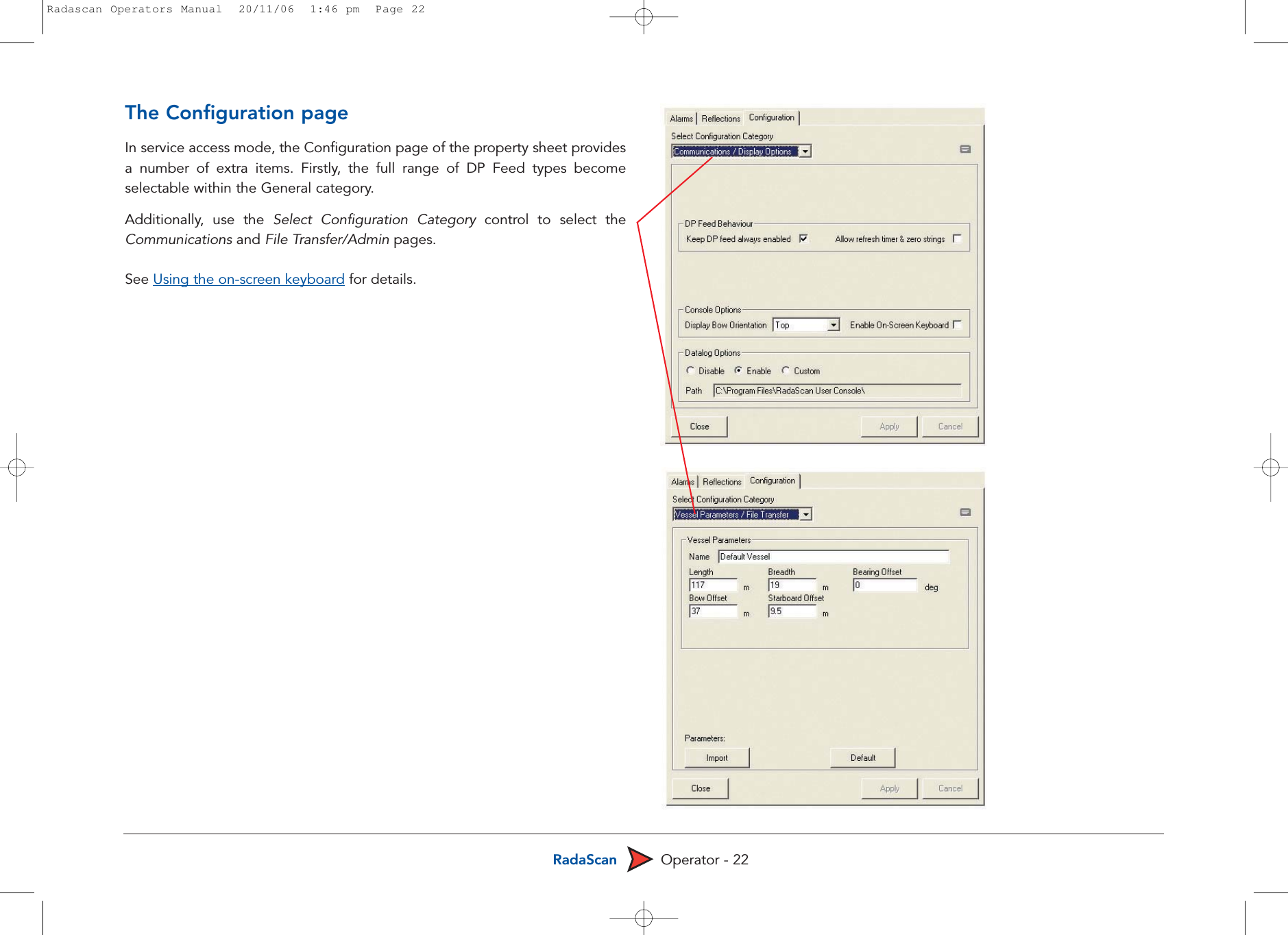
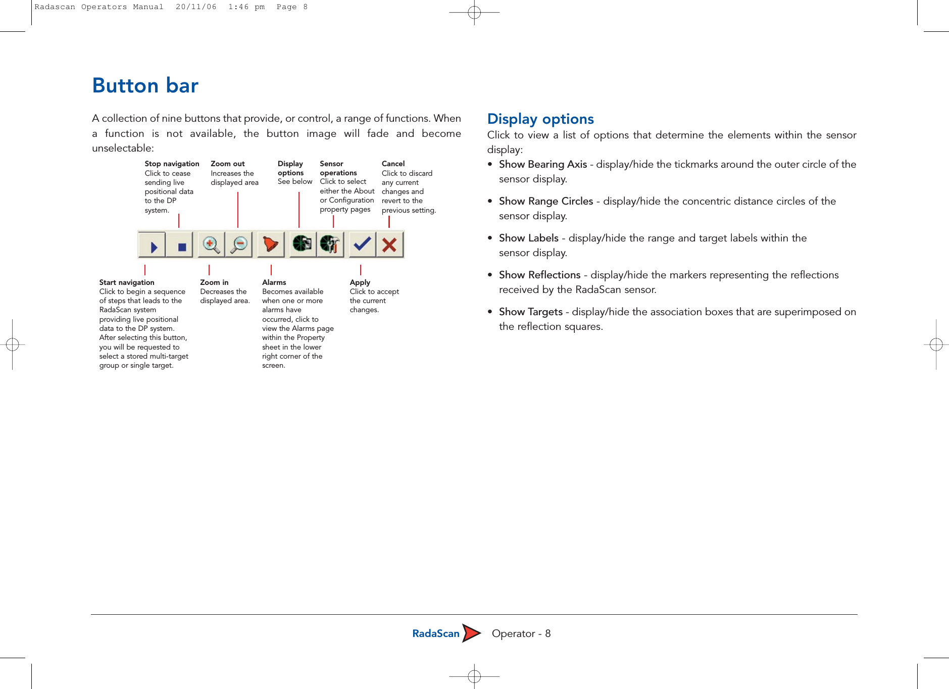
![RadaScan Operator - 21There are many settings within RadaScan Console that can seriously affectsystem operation if they are incorrectly adjusted. For this reason they areconcealed until you enter service access mode. IMPORTANT: Indiscriminate adjustment of parameter settings can adverselyaffect the operation of RadaScan. It is not advisable to edit the settings unlessdirected to do so by a qualified technician or Guidance Navigation Limited.Service access mode can be entered by plugging an engineer USB key into anyavailable USB port on the console computer prior to starting the application. Itis recommended that the application be re-started without the key in order toreturn to normal user mode.To obtain and use a temporary service access code1 Within the RadaScan Console application, view the About page tab.2 Click the Service Access button in the lower right corner of the About page.A dialog will be displayed and will show a Service request code. Note: The service request code is constructed as two groups of six capital letters [A-Z] separated by a + sign. There are never any numerals in a serviceaccess code. 3Transmit the service access code to Guidance Navigation Limited (support@radascan.co.uk) or an authorised customer service representative.A corresponding Service access code will be supplied to you. This code is non-transferable and will operate only with current Console system for a limited period.4 Enter the received code into the Service access code field of the displayed page and click OK. Service access will be granted on this system for a maximum period of 12 hours, however, the mode will be automatically ended after 20 minutes - you need to re-click the Service Access button within the About page. Note: The service access code is a 12 digit hexadecimal number [0-9, A-F].!Service access code dialog showing the request code andan area to enter a corresponding access codeEntering service access modeRadascan Operators Manual 20/11/06 1:46 pm Page 21](https://usermanual.wiki/Guidance-Marine/RADASCAN.USERS-MANUAL/User-Guide-917507-Page-23.png)