Guidance Marine RADASCAN RADASCAN User Manual Radascan Installer
Guidance Navigation Ltd. RADASCAN Radascan Installer
UserManual.wiki
>
Guidance Marine
>
RADASCAN User Manual
>
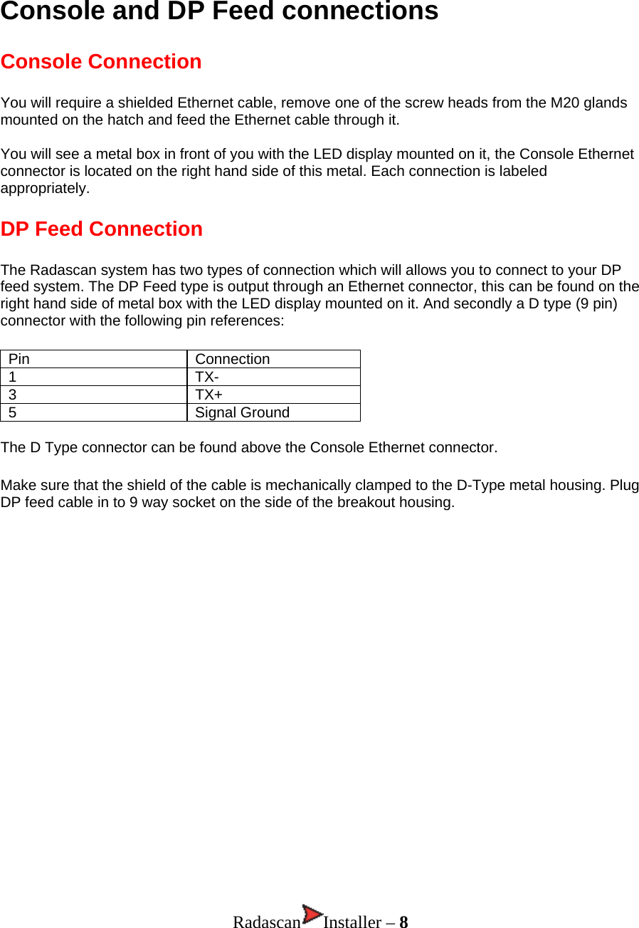
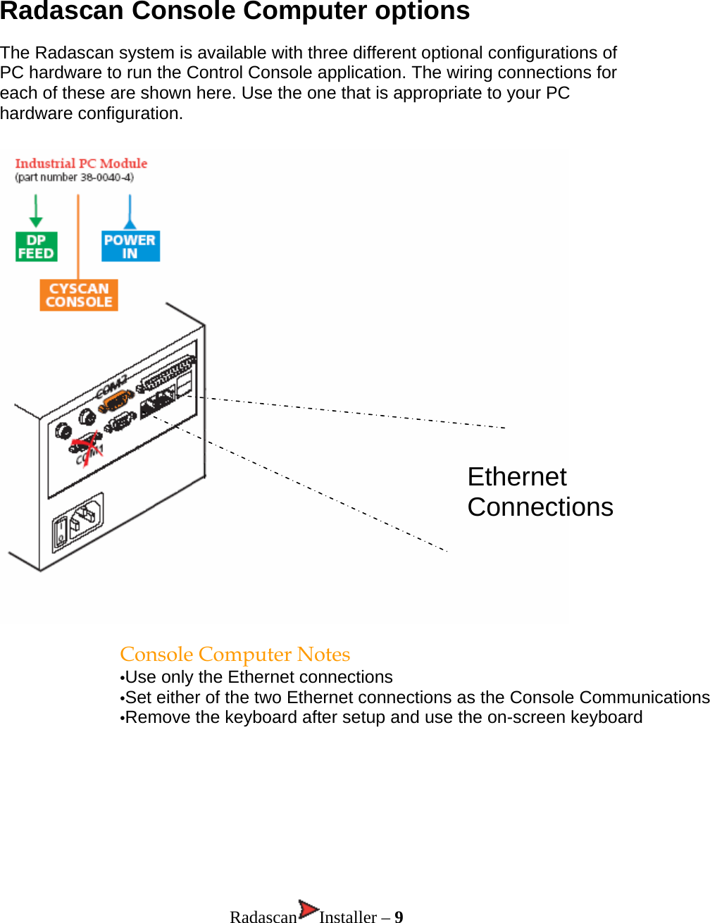
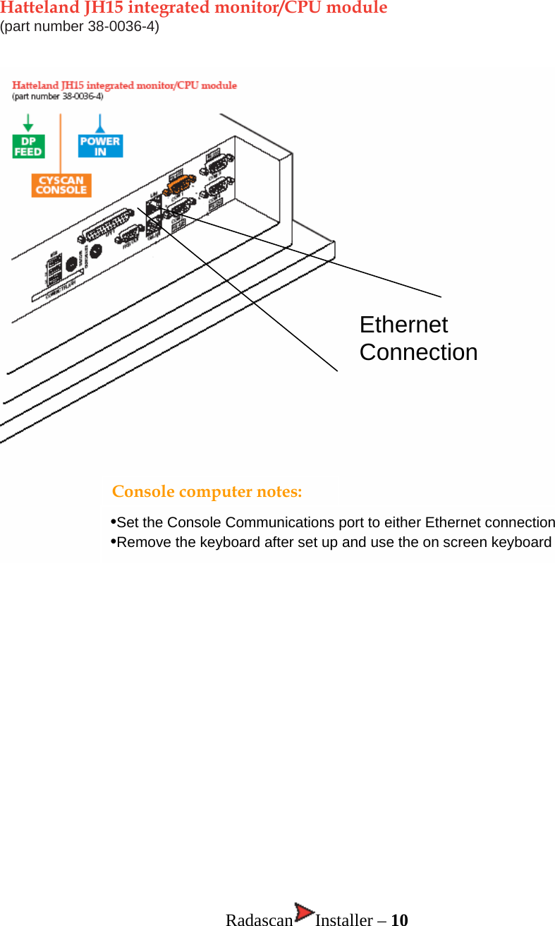
INSTALLATION MANUAL
Contents
1.
USERS MANUAL
2.
INSTALLATION MANUAL
INSTALLATION MANUAL
Navigation menu
Upload a User Manual
Namespaces
Wiki Guide
HTML
PDF
Info
Views
User Manual
Discussion / Help
Navigation
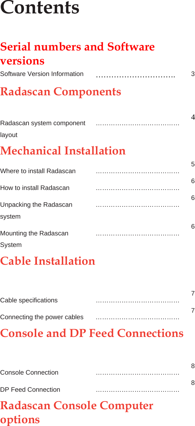

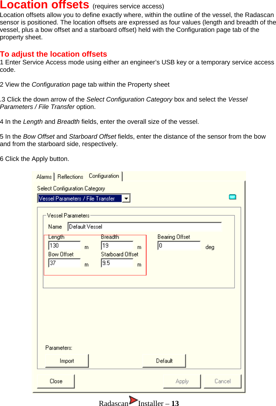
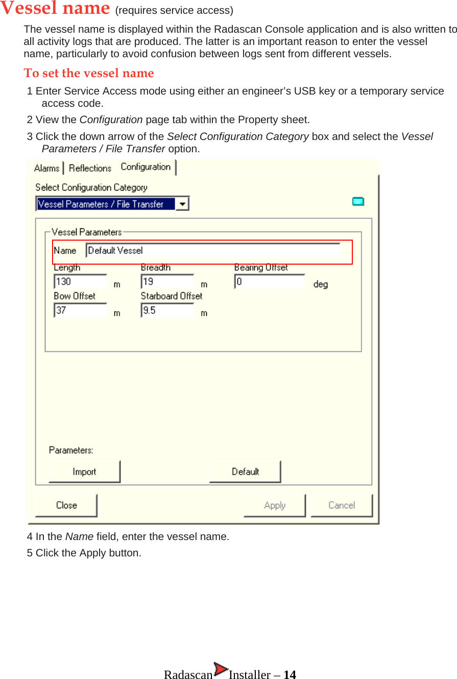
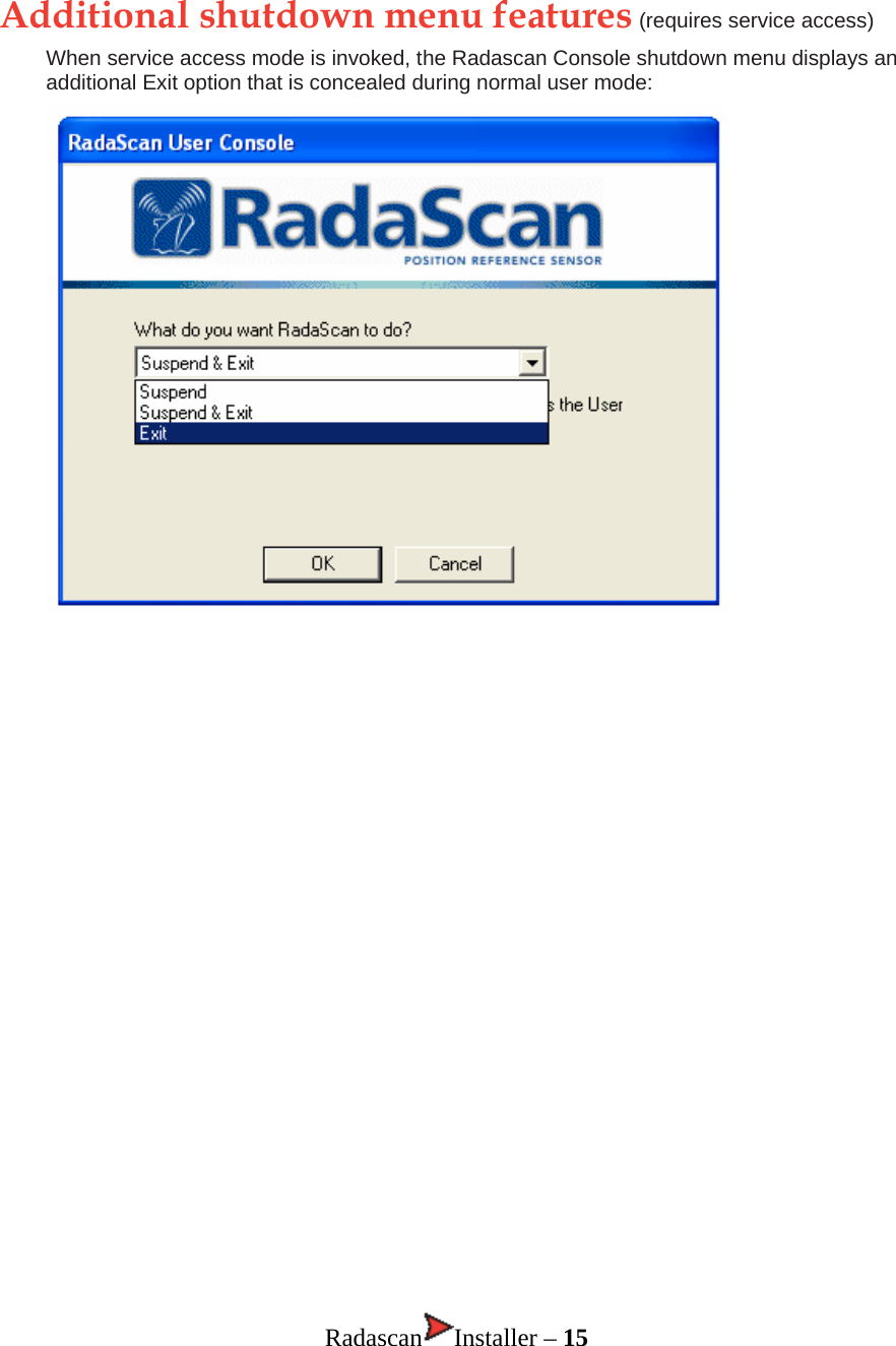
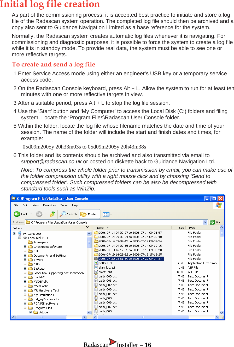
![Entering service access mode There are many settings within Radascan Console that can seriously affect system operation if they are incorrectly adjusted. For this reason they are concealed until you enter service access mode. There are two ways to enter service access mode: • Insert an engineer’s USB key into one of the Console computers’ USB ports, or • Obtain a temporary service access code from either Guidance Navigation Limited or an authorized customer service representative. To obtain and use a temporary service access code 1 Within the Radascan Console application, view the About page tab within the Property sheet. 2 Click the Service Access button in the lower right corner of the About page. A dialog will be displayed and will show a Service request code. Note: The service request code is always constructed as two groups of six capital letters [A-Z] separated by a + sign. There are never any numerals in a service access code. 3 Transmit the service access code to Guidance Navigation Limited (support@radascan.co.uk) or an authorized customer service representative. A corresponding Service access code will be supplied to you. This code is non-transferable and will operate only with current Console system for a limited period. 4 Enter the received code into the Service access code field of the displayed page and click OK. Service access will be granted on this system for a maximum period of 12 hours, however, the mode will be automatically ended after 20 minutes - you need to re-click the Service Access button within the About page. Note: The service access code is a 12 digit hexadecimal number [0-9, A-F]. A Service Access USB Key is available to authorized service partners (part number 20-0076-4). This can be obtained from Guidance Navigation Limited. Email radascan@guidance.eu.com Radascan Installer – 12](https://usermanual.wiki/Guidance-Marine/RADASCAN.INSTALLATION-MANUAL/User-Guide-918644-Page-16.png)
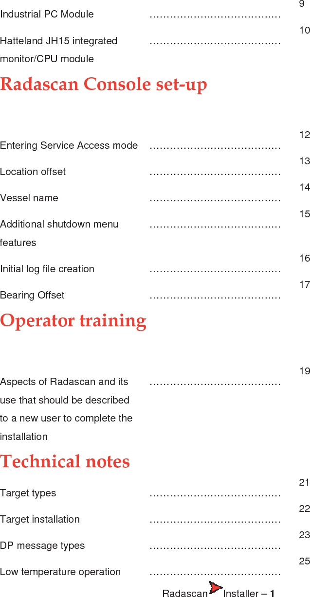
![TECHNICAL NOTE 3 DP message types Introduction The Radascan distinguishes between two operating modes; (a) single target/prism, and (b) multiple target operation which can affect the type of data sent to the DP feed. However, independent of this operation mode different DP feed message types can be selected from a range of formats. The DP message update rate is 1 Hz. Each format name is followed by the corresponding selection value that can be used in a bitwise combination with other selection values (registry key:DpFedAllowSelection) to define which DP feed formats are available for selection by the normal DP operator. Typically this should be set to only a single value corresponding to the DP system the sensor is connected to. The default DP feed selection value for normal operators is 0x0007 corresponding to the NMEA0183R, NMEA0183P and ASCII17 formats. In engineer mode all formats with selection values below 0x00FF are available. NMEA0183R Format (0x0001) A 42 character string: $RLS,±AAA.AA,±BBB.BB,S1,XXX.XXX,S2,HHHH*CC<CR><LF> • $RLS message header • AAA.AA resolved raw position in A axis [metres] • BBB.BB resolved raw position in B axis [metres] • S1 status of position data in A and B axis, A – available; V – void • XXX.XXX resolved bearing of vessel with respect to A axis [degrees] • S2 status of bearing data, A – available; V – void • HHHH status word in hexadecimal. Up to 16 bits defined by Guidance Navigation in a separate specifications document • CC computed checksum in hex • <CR> Carriage return (ASCII 0D hex) • <LF> Line feed (ASCII 0A hex) Note: when the reflectors are installed on a fixed platform and their co-ordinates are entered in Northings and Eastings, AAA.AA and BBB.BB will also be in Northings and Eastings and XXX.XXX will be true vessel heading. NMEA0183P Format (0x0002) A 42 character string: $RLS,±AAA.AA,±BBB.BB,S1,XXX.XXX,S2,HHHH*CC<CR><LF> • $RLS message header • AAA.AA resolved primary position in A axis [metres] • BBB.BB resolved primary position in B axis [metres] • S1 status of position data in A and B axis, A – available; V – void • XXX.XXX resolved bearing of vessel with respect to A axis [degrees] • S2 status of bearing data, A – available; V – void • HHHH status word in hexadecimal. Up to 16 bits defined by Guidance Navigation in a separate specifications document Radascan Installer – 23](https://usermanual.wiki/Guidance-Marine/RADASCAN.INSTALLATION-MANUAL/User-Guide-918644-Page-27.png)