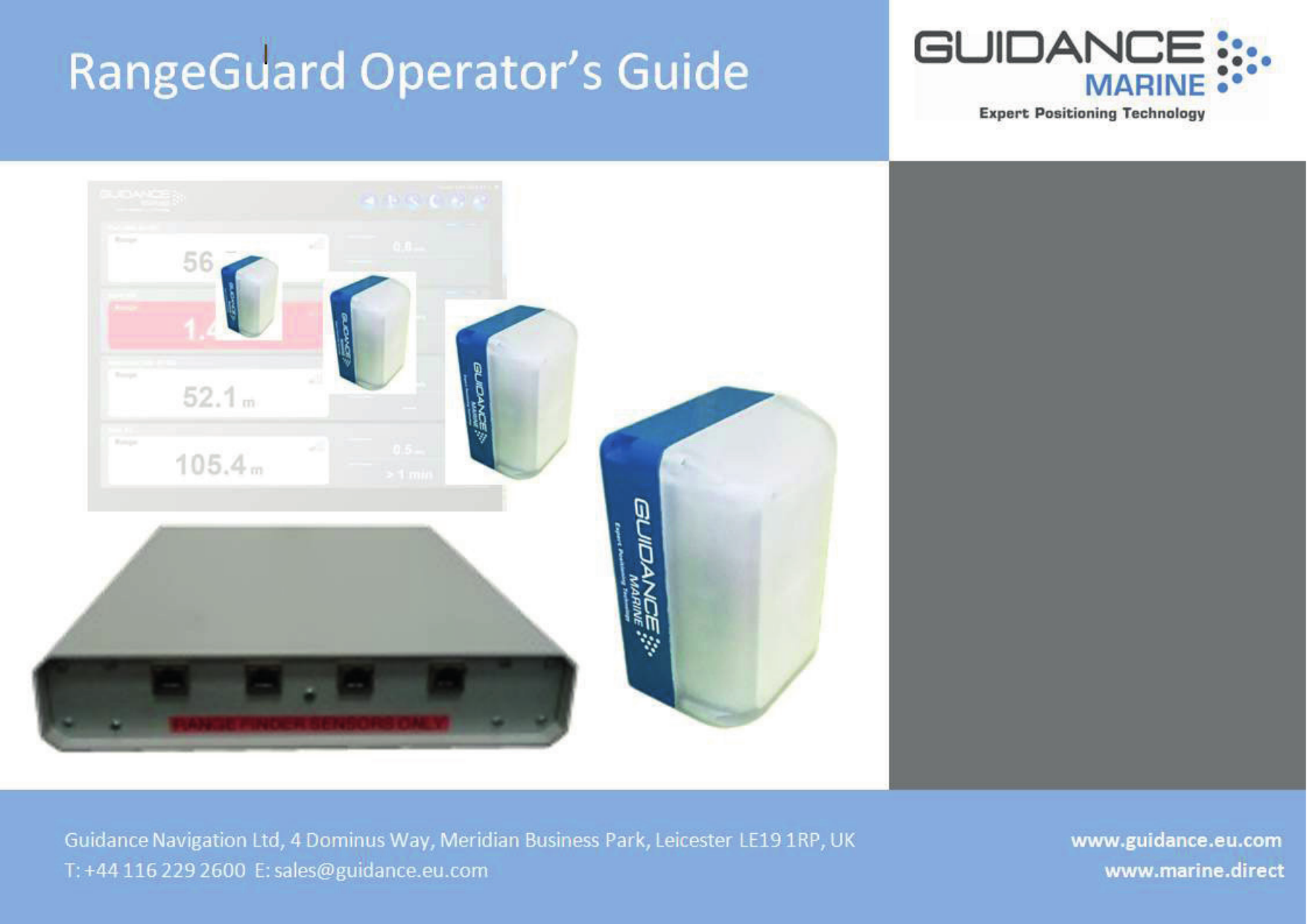
Guidance Marine RANGEGUARD RangeGuard Wide Beam 20-0183-1 User Manual 94 0447 4 A Rangeguard Operators Guide

Guidance Navigation Ltd. RangeGuard Wide Beam 20-0183-1 94 0447 4 A Rangeguard Operators Guide

User manual

Guidance Marine Ltd,4 Dominus WayMeridian Business ParkLeicesterLE19 1RPUKTel: +44  116 229 2600 Tel (Customer Services): +44  116 229 2665 Fax: +44 116 229 2604Email: customerservices@guidance.eu.com Web: www.guidance.eu.com          www.marine.directCopyright © 2015 Guidance Marine Limited. All Rights Reserved.Copyright in the whole and every part of this document belongs to Guidance Marine Limited (the “Owner”) and may not be used, sold, transferred, copied or reproduced in whole or in part in any manner or form or in or on any media to any person other than in accordance with the terms of the Owner’s Agreement or otherwise without the prior written consent of the Owner.”Windows” is a trademark of Microsoft Corporation. All other brand or product names are trademarks or registered trademarks of their respective companies or organisations.Serial No:Date of Shipment from UK:Sensor Software Version: Software Version:Rangeguard Operator’s GuideIssue Date: 21/04/2015Document No: 94-0447-4-A     0191
l 3Document HistoryDocument Number Changes Issue Date94-0447-4-A First Release of Rangeguard Operator’s Guide 21/04/2015
l 4IntroductionSystem Overview ...................................................................................................... 6Getting StartedStart Up and Shut Down .......................................................................................... 8Start Up.............................................................................................................................................. 8Shut Down ......................................................................................................................................... 8Screen Layout .......................................................................................................... 9Table View  ....................................................................................................................................... 10Display Options ...................................................................................................... 12Selecting/Deselecting Sensors .............................................................................. 13Measurement AlgorithmsSelection of Measurement Algorithm ..................................................................... 15Setting the Range Limits ........................................................................................ 16Closest Algorithm ................................................................................................... 17Manual Threshold Algorithm .................................................................................. 18Max Peak Algorithm ............................................................................................... 19Peak Lock Algorithm .............................................................................................. 20AppendicesSystem Specications ............................................................................................ 22FCC Warning Statement ........................................................................................ 23Index ....................................................................................................................... 24Table of Contents
l 5IntroductionWelcome to the RangeGuard Operator’s Guide. It explains how to use the RangeGuard system once it has been fully installed. For instructions on how to install RangeGuard onto a vessel, refer to 94-0448-4 RangeGuard Installer’s Guide.The System Overview on page 6 describes the different components of the system and how they work together.The Getting Started section on page 8 explains how to get the system up and running and how to shut it down again. It also details what you will see on the RangeGuard Display screen when the system is running, and how to interpret the information.The Measurement Algorithms section on page 14 describes the different ways that RangeGuard can measure the distance to an object.Further useful information is included in the Appendices section on page 21.
l 6The RangeGuard system provides object detection and distance measurements using continuous wave radar sensors. These operate on a licence-exempt Short Range Device basis at 24.15GHz. The system comprises a control box, up to four sensors and a graphical user interface which can be accessed from any device connected to the same network.  The sensors are typically positioned around the outside of a vessel and connected to the control box via standard Cat5e Ethernet cable up to a maximum length of 100m; longer cables can be made using cable with additional cores.  The sensors have a fixed elevation beam width of 11° (+/-5.5°) and two options of azimuth beam: 11° (Narrow Beam) and 90° (Wide Beam). Each sensor measures the range to the nearest obstacle by default or to a selected obstacle if preferred.System OverviewRangeGuard Display - the user interface - is run from a web browser. It is recommended that either the user interface supplied by Guidance Marine or else Google Chrome are used.  Other browsers will work but without guarantee.  Once the control box has been connected to the network, type its IP address (default 192.168.2.231) into the web browser address bar and the user interface will appear in Bird’s Eye View.
l 7Getting StartedThis section describes RangeGuard Display and basic use of the system. It contains the following pages:• Start Up and Shut Down (Page 8)• Screen Layout (Page 9)• Display Options (Page 12)
l 8Start Up and Shut DownStart UpTo Open RangeGuard Display   1.  Ensure that the control box is powered on.2.  Double-click on the RangeGuard icon.   (Or run the RangeGuard Display application from:  Start > All Programs > Guidance RangeGuard > RangeGuard Display).3.  The display will appear in full screen mode, with the Bird’s Eye View open. Shut DownTo Close RangeGuard Display   Click on the X button in the top right corner of the screen.Bird’s Eye ViewSide Bar
l 9Screen LayoutThe RangeGuard Display presents positional information in one of three main formats, Bird’s Eye View, Table View and Single Sensor View.Bird’s Eye View (BEV)The BEV depicts the operational area of the RangeGuard system from above. By default, the BEV is centred on an image of the vessel and around this it shows a radar beam, range measurement and received signal level for each sensor that has detected an object. Clicking on any one of the radar beam sectors causes a shift in the BEV so that  the object detected by that beam is now at or close to the centre. The colour of the beam changes to reflect the range of the object (red, amber or green in accordance with configured alarm limits). The colours of the other beams also change to reflect the ranges of the objects that they have detected.In order to switch to the BEV from one of the other views, click on the Bird’s Eye View button in the top right of the display screen:Bird’s Eye View without a sensor in focusBird’s Eye View focussing on one sensorThe contents of the BEV can be enlarged or reduced by means of the Zoom In and Zoom Out buttons in the bottom right of the screen. Six zoom levels are available and the current level is indicated by the yellow bars between the buttons:The position represented by the mouse cursor on the BEV, taking into account the zoom level, is displayed above the zoom buttons, e.g. Mouse at 117°, 68.10 m from vessel centre. These numbers are updated as the cursor is moved across the screen.
l 10Table View By default, this displays the positional data for all of the currently chosen sensors, in the form of a table. For each sensor this comprises:• Range :  The measured distance to the object detected by the sensor. The background of this field is coloured according to the range value:Red for ranges below configured red alarm limit Amber for other ranges below configured amber alarm limitWhite for longer ranges or if no measurement is made  • Signal Strength :  Represented by filled segments of a bar chart and – if the cursor is moved over the chart - numerically in the tooltip. • Speed:  This is calculated from the most recent range measurements and marked as “Closing Speed” if the sensor is approaching the object and “Separating Speed” if moving away.• Time to Contact:  How long it would take for the vessel to make contact with the detected object, based on the currently-displayed closing speed. Displayed as a number of seconds or as “> 1 min”.  In the case of a separating speed, the field contains “---“.Each row in the table contains a Profile button, which replaces the positional values for a sensor with a Profile plot:Screen Layout (Continued)This represents the signal returned at each range – a large vertical peak means that an object exists at the range shown by the horizontal axis.The buttons along the top of the graph allow you to choose the way in which the system  interprets the received signals.
l 11Screen Layout (Continued)In order to switch to Table View from one of the other views, click on the Table View button in the top right of the display screen:Single Sensor View This is essentially a magnified form of the data in a single row of the Table View, with the addition of downward-pointing chevrons to indicate a closing speed or upward-pointing chevrons to indicate a separating speed.  At very low speeds, only the top chevron is coloured (red for closing and green for separating). At higher speeds, the second and third chevrons are also coloured. Single Sensor View can show the positional data in extra-large numerals:Alternatively, by clicking on the Expand Spectrum button in the bottom right corner the screen is split between positional data and the profile plot:Click on the Collapse Spectrum button to maximise the positional data again. In order to switch to Single Sensor View:Either        Double-click on one of the radar beams on the Bird’s Eye View Or         Double-click on one of the rows in Table View.
l 12Display OptionsTo provide clear visibility during daytime operation and minimal glare during night shifts, the RangeGuard Display offers two display modes: Day View and Night View. In either mode the brightness can be further modified by brightness adjustment buttons.To change the day/night view and adjust brightness:If in day mode, click on the Toggle Night Mode button:  If in night mode, click on the Toggle Day Mode button:  Click on the Decrease Brightness button to dim the screen:  Click on the Increase Brightness button to brighten the screenHotkey Buttons
l 13Selecting/Deselecting SensorsA RangeGuard system can be run with up to four sensors. The overall sensor count and characteristics of each sensor are configured at installation time in the password-protected RangeGuard Control Panel (see 94-0448-4 RangeGuard Installer’s Guide for details).However, each sensor can be selected/deselected on the fly, using the Choose Sensors button:  Click on this button to obtain a menu containing the label of each sensor and a checkbox:Only data from currently-selected sensors is shown on the Bird’s Eye View and Table View.
l 14This section describes the different ways that RangeGuard can make measurements. It contains the following pages:It contains the following pages:• Selection of Measurement Algorithm (Page 15)• Setting the Range Limits (Page 16)• Closest Algorithm (Page 17)• Manual Threshold Algorithm (Page 18)• Max Peak Algorithm (Page 19)• Peak Lock Algorithm (Page 20) Measurement Algorithms
l 15Selection of Measurement AlgorithmThere is a measurement algorithm setting for each sensor in the system. It is selected via the buttons above the sensor’s profile plot in Table View or Single Sensor View:The algorithms use different methods of extracting a range measurement from the reflected signal received by the sensor.  Each algorithm potentially gives a different range value in any given situation, so it is important to choose one that is appropriate for your needs. You may also want to disregard reflections from the shortest or longest ranges; see Setting the Range Limits on page 16.
l 16Setting the Range LimitsBy default, when calculating the range of an object, the system takes into account all reflected signals that it receives. However, it is possible to mask out reflections from the shortest and/or longest ranges, for example to ignore an overhanging feature of the vessel’s own structure.To set the Range Limits for a sensor:1.   Go into Table View and open the Profile for the relevant sensor, or else enter Single       Sensor View and expand the Profile. 2.   Click and drag one or both of the green Range Limit sliders:3.  Leave the left-hand slider at the range below which you want all reflections to be     ignored.4.  Leave the right-hand slider at the range above which you want all reflections to be   ignored.Alternatively, double-click either of the sliders and type a numerical value into the entry box:Range Limit SlidersThe beam for this sensor on the Bird’s Eye View is sized according to these limits:
l 17Closest AlgorithmWhen the Closest algorithm is selected, RangeGuard bases its range measurement on the shortest range peak in the reflected signal, within the Range Limits and above the Signal Threshold. For this algorithm the Signal Threshold is fixed at 20dB above the nominal noise floor. The measured range is indicated on the Profile Plot by a vertical red line:                                                 Measured Range (approx 100m)
l 18Manual Threshold AlgorithmWhen this algorithm is selected, the Signal Threshold is adjustable, instead of being fixed at 20dB. Move the red slider up or down the dB axis to a suitable threshold level:Signal  Threshold                                              Measured RangeNote that the Manual Threshold algorithm measures the lowest range at which the signal breaks through the threshold, as distinct from the Closest algorithm which uses the lowest-range peak.Alternatively, double-click the red slider and type a numerical value into the entry box:
l 19With this algorithm no Signal Threshold is applied and the strongest reflected signal within the Range Limits is used for the range measurement, rather than the closest:Measured RangeMax Peak Algorithm
l 20Peak Lock AlgorithmWith this algorithm, you can manually select a peak within the Range Limits that is not necessarily the closest or highest. The system then locks onto it and reports its range.In order to select a peak, move the red slider along the Range axis:Measured RangePeak Picker
l 21This section contains the following appendices:• System Specications (Page 22)• FCC Warning Statement (Page 23)• Index (Page 23)Appendices
l 22System SpecificationsSensorTransceiver Type Frequency Modulated Continuous Wave (FMCW)Frequency Band 24.05GHz – 24.25GHz (Licence Exempt Short Range Device)Maximum Power Output <100mW EIRP  (EN 300 440 Compliant)Maximum Operating Range 300mMinimum Operating Range  1mRange  Accuracy* ±2cm + 0.1% of RangeAngular  Accuracy* N/A Azimuth Beam width 90° or 11°  (10dB Width)Target Detection Automatic or by manual selectionVertical Beam Height +/- 5.5°Vessel InterfaceSensor Power 85 to 264v AC 45-65 Hz 5A, Max 100WSensor Control  Analogue and Digital control on CAT 5e  SCTPSensor DP Feed  N/ASupported DP Systems N/ASensor Control  Sensor Control capable of displaying 4 sensors simultaneouslySensor Control Protocol Ethernet EnvironmentalAmbient Temperature Range -25 to +55°CAtmospheric Conditions Operates in fog, heavy rain, snow and ice conditionsWater and Dust Protection (Sensor)IP67 certifiedStandards Compliance EN 300 440-1 and  2, EN 60945 & EN301 843-1 (EMC) EN 60936:2002, Annex D, ITU-R Recommendation RM. 1177 European Directive 2004/108/EC1000mm (worst case) @ 0.3° deflectionEN60945 IP66 ratedRF Immunity Resistant to S and X band Radar when installed as recommendedSensor MechanicalHeight 23 cmWidth 17 cmDepth 13 cmWeight 4 kgMax Cable run per sensor  Up to 100m (CAT5e SCTP cable, Min AWG 24)
l 23FCC Warning Statement• This device complies with Part 15 of the FCC Rules.   Operation is subject to the following two conditions:  (1) This device may not cause harmful interference, and  (2) This device must accept any interference received, including interference that may    cause undesired operation.• This equipment complies with FCC radiation exposure limits set forth for an uncontrolled environment. End users must follow the specific operating instructions for satisfying RF exposure compliance. This transmitter must not be co-located or operating in conjunction with any other antenna or transmitter.• Changes or modifications not expressly approved by the party responsible for compliance could void the user’s authority to operate the equipment.
l 24FFCC Warning Statement  23HHotkey Buttons  12OOverviewSystem  6SShut Down  8Side Bar  8Start Up  8System Overview  6Index

Navigation menu