Guidance Marine VALIDATOR Marine Direction Finding X-Band Radar User Manual 94 0505 4 C Artemis Validator Operator s Guide
Guidance Marine Ltd. Marine Direction Finding X-Band Radar 94 0505 4 C Artemis Validator Operator s Guide
UserManual.wiki
>
Guidance Marine
>
VALIDATOR User Manual
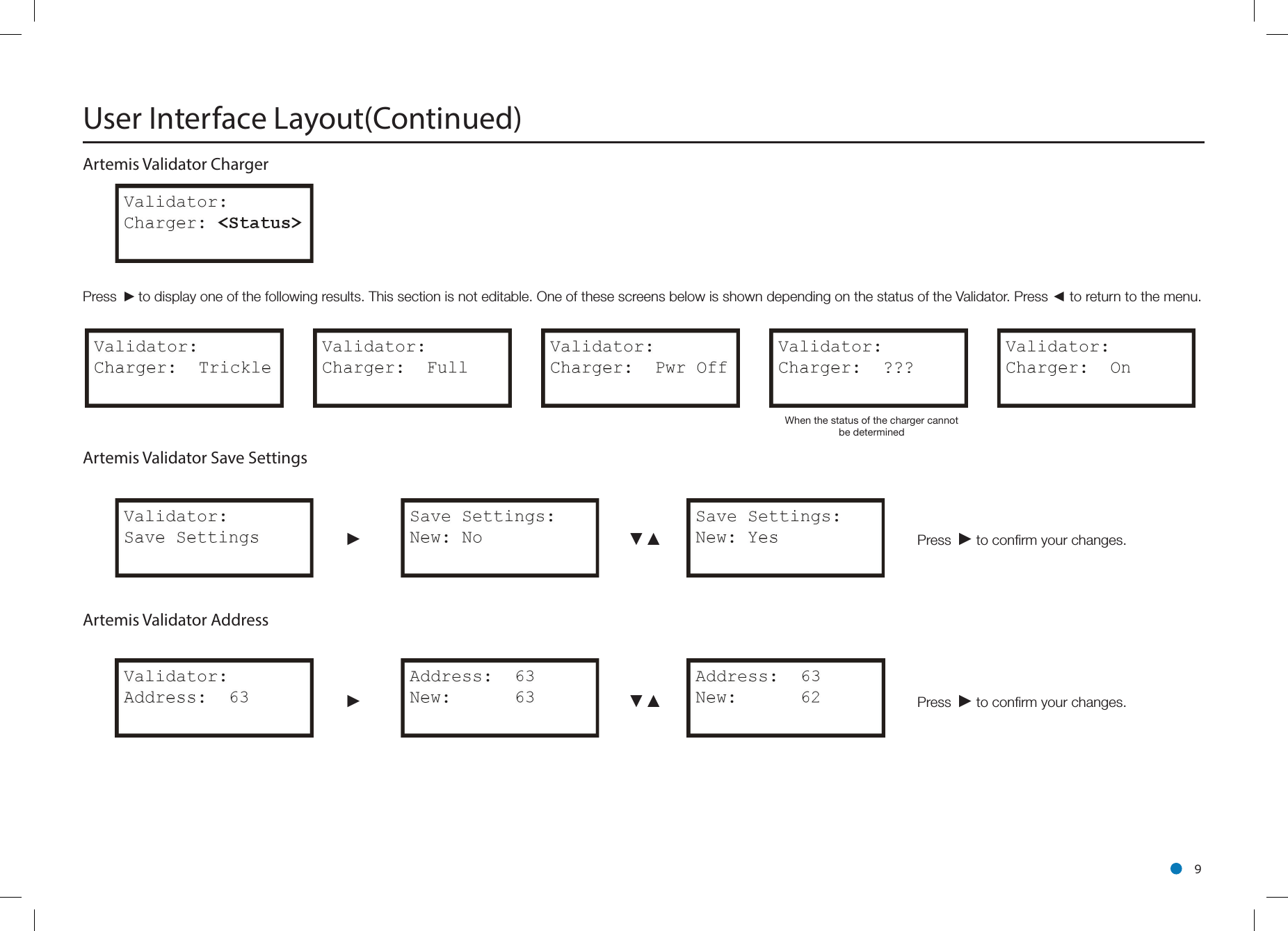
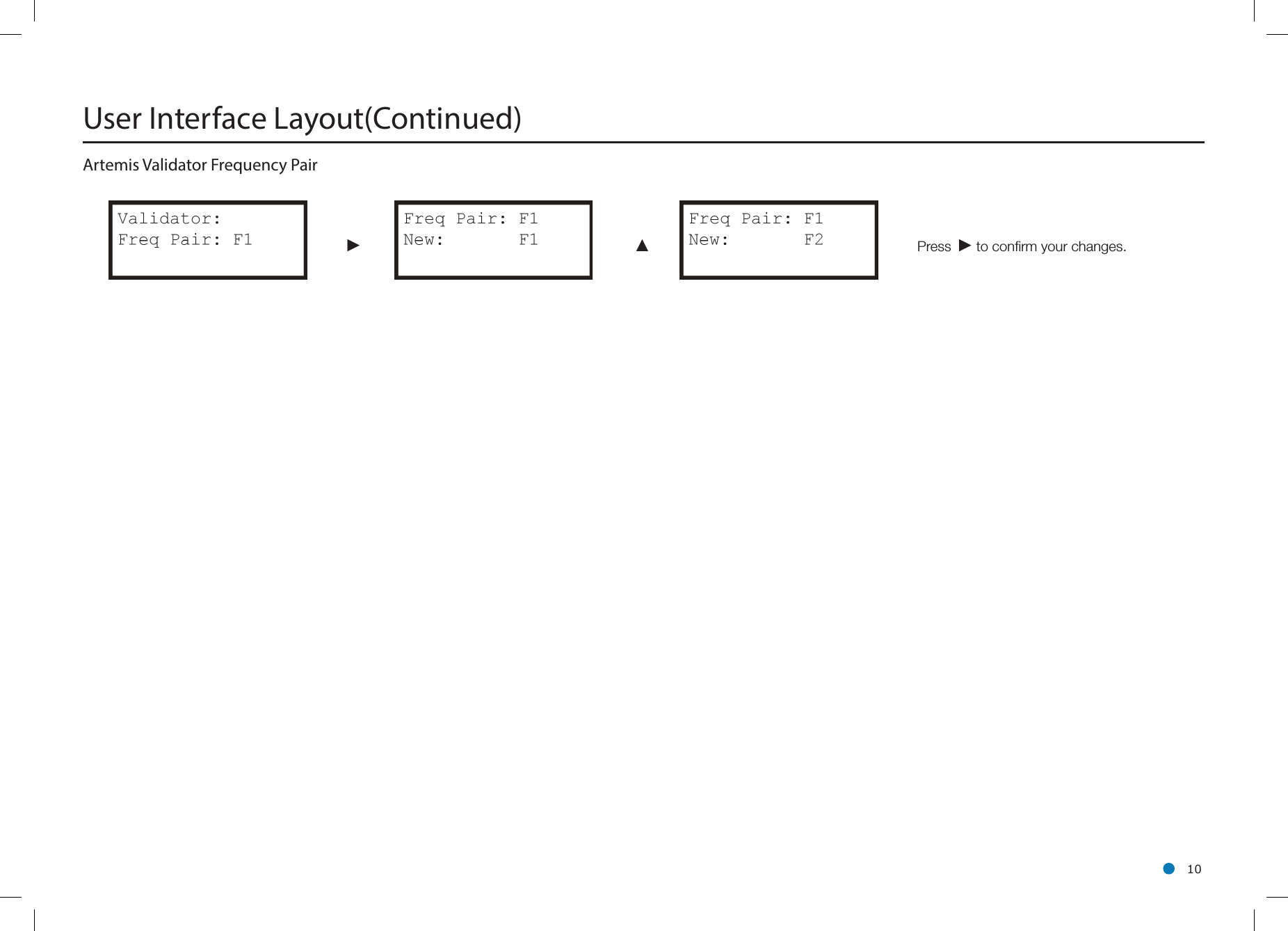
Operators Guide
Navigation menu
Upload a User Manual
Namespaces
Wiki Guide
HTML
PDF
Info
Views
User Manual
Discussion / Help
Navigation