Guidance Marine VALIDATOR Marine Direction Finding X-Band Radar User Manual 94 0505 4 C Artemis Validator Operator s Guide
Guidance Marine Ltd. Marine Direction Finding X-Band Radar 94 0505 4 C Artemis Validator Operator s Guide
Operators Guide
Guidance Marine Ltd, 5 Tiber Way, Meridian Business Park, Leicester LE19 1QP, UK
T: +44 116 229 2600 E: sales@guidance.eu.com
Artemis Validator Operator’s Guide
W
A
R
R
A
N
T
Y
S
e
e
o
u
r
s
t
a
n
d
a
r
d
t
e
r
m
s
o
f
s
a
l
e
Q
U
A
L
I
T
Y
A
S
S
U
R
E
D
3
YEAR
www.guidance.eu.com
www.marine.direct
Guidance Marine Ltd,
5 Tiber Way
Meridian Business Park
Leicester
LE19 1QP
UK
Tel: +44 116 229 2600
UK Support: +44 116 229 2665
(365 days a year, 08:00 - 20:00 hours UTC)
customerservices.uk@guidance.eu.com
USA Support: +1 504 305-1120
customerservices.us@guidance.eu.com
Asia Support: +65 6734 6365
customerservices.sg@guidance.eu.com
Web: www.guidance.eu.com/customer-support
Copyright © 2016 Guidance Marine Limited. All Rights Reserved.
Copyright in the whole and every part of this document belongs to Guidance Marine Limited (the “Owner”)
and may not be used, sold, transferred, copied or reproduced in whole or in part in any manner or form
or in or on any media to any person other than in accordance with the terms of the Owner’s Agreement
or otherwise without the prior written consent of the Owner.”Windows” is a trademark of Microsoft
Corporation. All other brand or product names are trademarks or registered trademarks of their respective
companies or organisations.
Serial No:
Date of Shipment from UK:
Artemis Validator Operator’s Guide
Issue Date: 21/03/2017
Document No: 94-0505-4-C
Document Number Changes Issue Date
94-0505-4-A First Release Artemis Validator Operator’s Guide 29/11/2016
94-0505-4-B Artemis Validator Operator’s Guide 02/03/2017
94-0505-4-C Artemis Validator Operator’s Guide with FCC 21/03/2017
Document History
FCC ID VYMVALIDATOR
FCC Warning Statement
This device complies with Part 15 of the FCC (USA Federal Communications Commission) rules.
Operation is subject to the following two conditions:
1. This device may not cause harmful interference, and
2. This device must accept any interference received, including interference that may cause undesired operation.
This equipment complies with FCC radiation exposure limits set forth for an uncontrolled environment. End users
must follow the specific operating instructions for satisfying RF exposure compliance. This transmitter must not
be co-located or operating in conjunction with any other antenna or transmitter.
Changes or modifications not expressly approved by the party responsible.
This equipment complies with the FCC RF radiation exposure limits set forth for an uncontrolled environment.
This equipment should be installed and operated with a minimum distance of 20cm between the radiator and
any part of your body.

l 3
Table of Contents
Introduction
System Overview ...................................................................................................... 4
User Interface
Start Up ................................................................................................................... 5
Shut Down ............................................................................................................... 5
Menu Structure ........................................................................................................ 5
Modifying Settings .................................................................................................. 7
Save Settings .......................................................................................................... 7
User Interface Layout
Artemis Validator Range Setting............................................................................... 8
Artemis Validator Test Result .................................................................................... 8
Artemis Validator FPGA Version ............................................................................... 8
Artemis Validator S/W Version .................................................................................. 8
Artemis Validator Charger ........................................................................................ 9
Artemis Validator Save Settings ............................................................................... 9
Artemis Validator Address ........................................................................................ 9
Artemis Validator Frequency Pair ........................................................................... 10
Operation
Conguration Procedure ........................................................................................ 11
Validation Procedure .............................................................................................. 11
Rechargable Artemis Validator
To Switch the Artemis Validator ON ....................................................................... 12
Charging
To charge the Artemis Validator .............................................................................. 12
Dimensions
Artemis Validator Dimensions ................................................................................ 13
l 4
System Overview
The Artemis microwave-based position reference system provides accurate positional data
to marine Dynamic Positioning (DP) control systems. It enables automated approach and
station keeping relative to another Artemis sensor on a rig or platform, or to another vessel.
The standard Artemis system includes:
• Two identical Antenna Units (or Sensors) configured, as a Mobile Station and a Fixed
Station.
• The Artemis Control PC, a Windows-based marine specification computer, running the
control software.
An alternative configuration - the Beacon system - involves the same components as
the standard system except for a non-rotating Beacon Unit instead of a Fixed Station. A
Beacon Unit does not provide an Azimuth measurement.
Antenna Units
The Mobile Station is mounted on the DP-Equipped vessel, ideally at the top of the main
mast. The Fixed Station is installed on a fixed platform if absolute positioning is needed or
on a moving platform or structure to provide relative positioning.
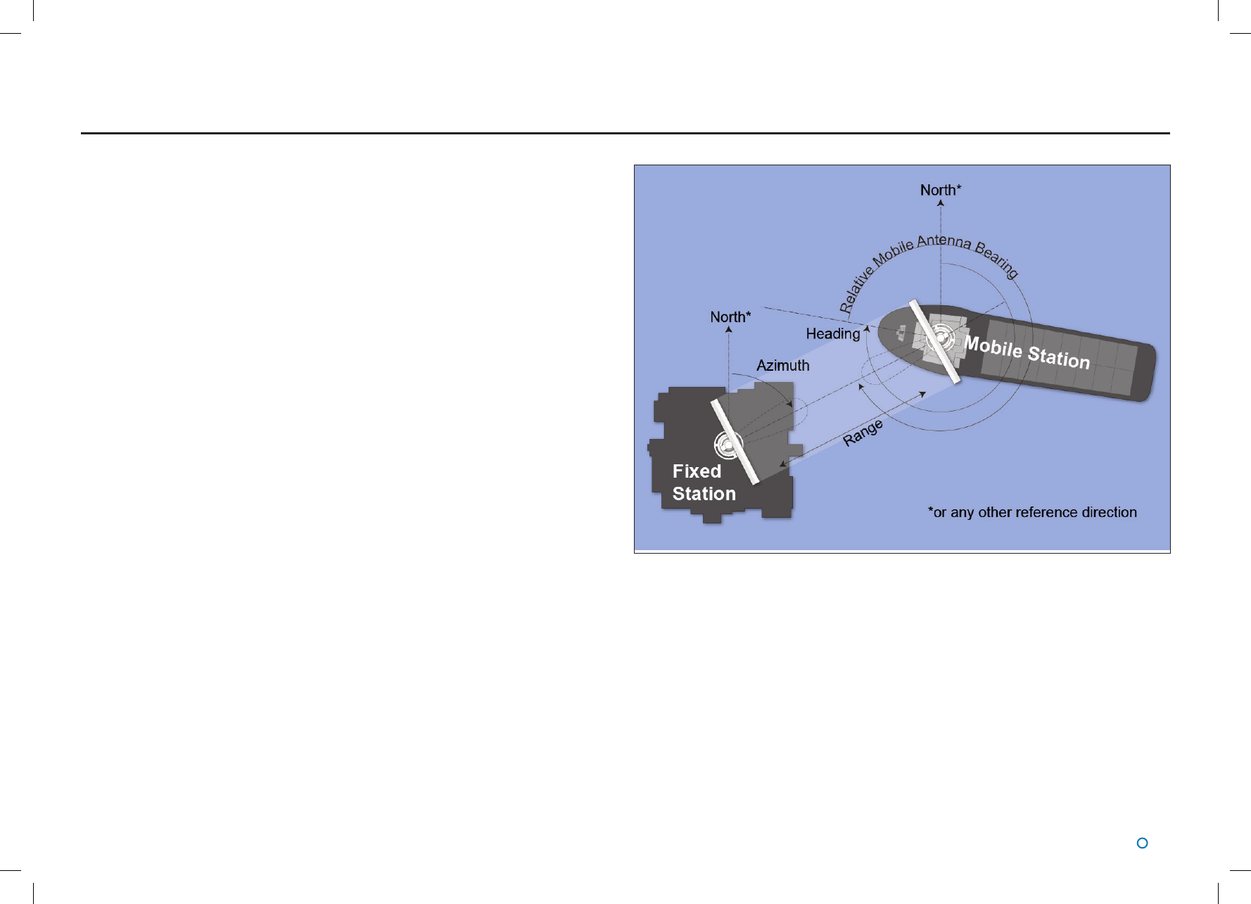
System Operation
In order to provide positional data to the vessel’s DP system, the Artemis system needs to
be “locked”. In this state, the antennae of the Fixed and Mobile Stations are facing each
other and automatically tracking by maintaining a continuous microwave link.
The distance between the sensors is obtained from the travel time of the microwave signal.
The bearing of the Fixed Station, with respect to the centre line of the vessel is measured.
The Fixed Station measures the Azimuth and reports it to the Mobile Station.
Introduction and System Overview
Artemis Validator
The Artemis Validator is a portable, battery powered Fixed Station simulator that can test an
Artemis Mk5 or Mk6 sensor at distances of up to 300m.
The Artemis Validator can simulate different ranges at frequency pair and address code
combinations to support validation of the operaton of a Mobile Artemis sensor.
Layout of a Standard Artemis System
Introduction
Welcome to the Artemis Validator Operator’s Guide. It explains how to use the portable
version of the Artemis Validator to confirm that an Artemis Mk5 or Mk6 position reference
sensor is in working order.
The System Overview sets the Artemis Validator in the context of the Artemis system as a
whole.
Note that whilst we endeavour to describe the functionality of the device correctly in this
document, we do not guarantee that it exactly represents the version of the device that you
are using.
l 5
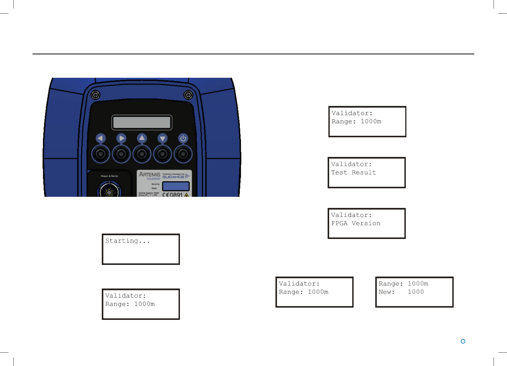
The user interface for the portable Artemis Validator consists of five buttons and an LCD
display.
Start Up
Switch on the Artemis Validator by pressing the On/Off button.
The information display briefly displays the following:
This is then replaced by the default top-level page:
User Interface
Menu Structure
The information display pages are arranged into a menu structure. The ▲▼►and ◄
buttons are used to navigate this structure.
At the top level of the menu structure, the first line of the display always reads “Validator:”.
Use the ▲and ▼buttons to scroll through the pages at this level. For example:
▼
▼
The ▲button takes you through the pages in reverse order.
If there is a sub-menu beneath a particular page, it is accessed by the ►button and the
first line of this page is the same as the second line of the top-level page, e.g.:
If there is no sub-menu, the ►button has no effect.
l 6
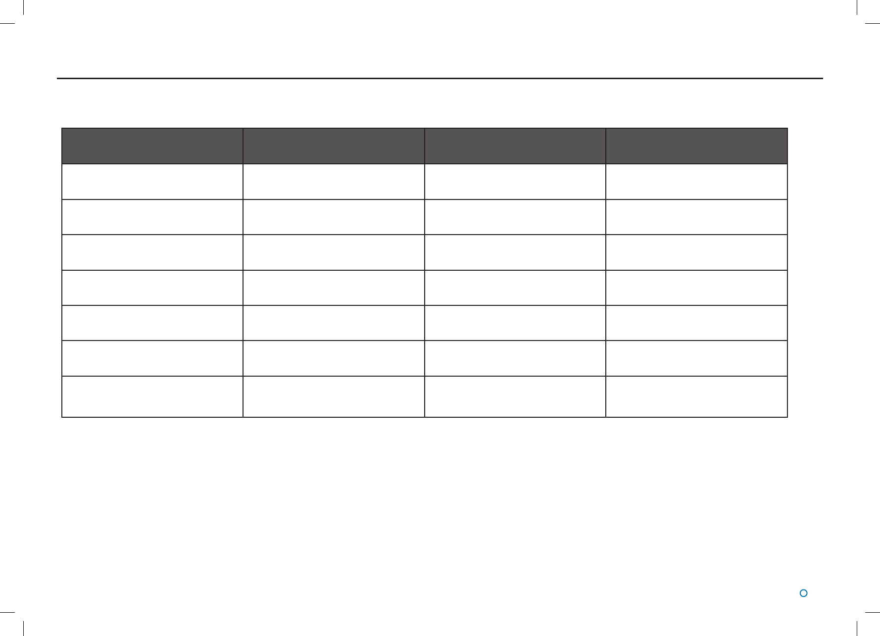
The full menu structure in order of scrolling is as follows:
User Interface (Continued)
Top-level Menu Option Possible Values Sub-Menu for Setting Modication Description
Range 500-10000m in 100m steps Yes Simulated range between Artemis
Validator and sensor
Ver xx.xx.xx.xx No Version number of Artemis Validator
rmware
Charger Off, Trickle, Full No Battery charger status
Supply On, Off No Battery charger connected
Save Settings No, Yes Yes Allows settings to be saved to non-
volatile memory
Address 0..63 Yes Address code of the Artemis unit that
is being validated
Freq Pair F0, F1, F2, F3 Yes Combination of frequencies
transmitted by Artemis Validator and
sensor
l 7
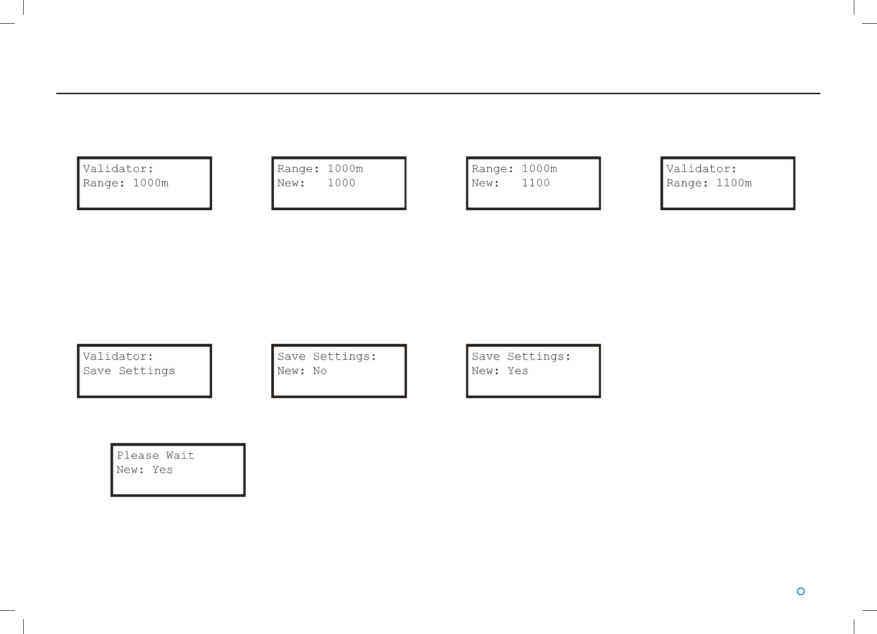
Modifying Settings
In general, the purpose of a sub-menu page is to allow you to modify a particular setting. The ▲and ▼buttons cause the “New” value to increase, decrease, scroll or toggle as
appropriate, whilst the existing value remains the same on the top line. For example to change the validation range from 1000m to 1100m:
►▲►
The ►button confirms the choice, or takes you into a submenu.
The ◄ button cancels a choice and returns to the next menu level up.
Any modified settings keep their new values only until the Artemis Validator is turned off. If you want the new values to persist indefinitely, use the Save Settings menu.
Saving Settings
Scroll to the Save Settings menu page at the top level of the menu structure. Press ►to reach the sub-menu and use ▲or ▼to change the value to “Yes”.
►▲
Press ►to confirm changes:
►
The settings are saved and the display returns to the top level of the menu.
User Interface (Continued)
l 8
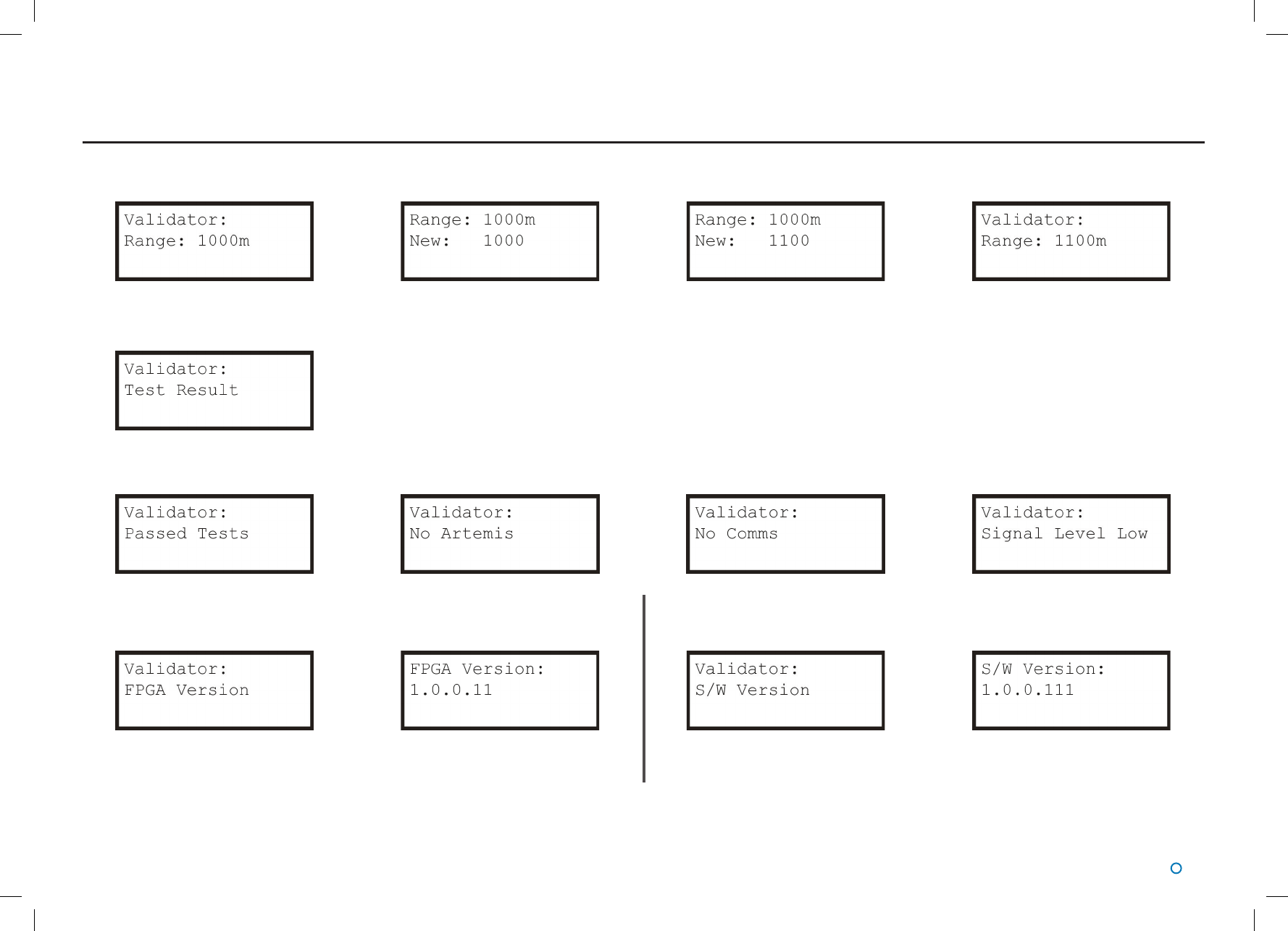
Artemis Validator Range Setting
► ▲►
Artemis Validator Test Result
Press ►to display one of the following results. This section is not editable. One of these screens below is shown depending on the status of the Validator. Press ◄ to return to the menu.
Artemis Validator FPGA Version Artemis Validator S/W Version
►►
Press ◄ to return to the menu. Press ◄ to return to the menu.
User Interface Layout
l 9
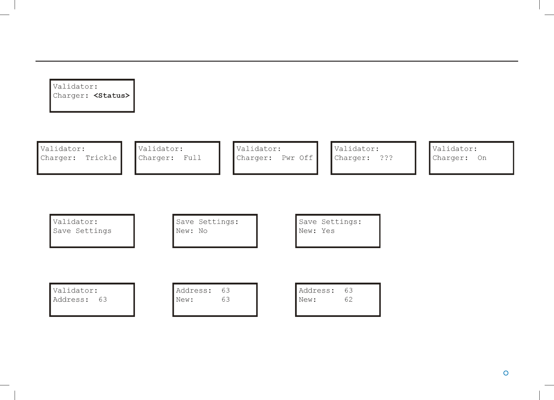
Artemis Validator Charger
Press ►to display one of the following results. This section is not editable. One of these screens below is shown depending on the status of the Validator. Press ◄ to return to the menu.
Artemis Validator Save Settings
► ▼▲ Press ►to confirm your changes.
Artemis Validator Address
► ▼▲ Press ►to confirm your changes.
User Interface Layout(Continued)
When the status of the charger cannot
be determined
l 10
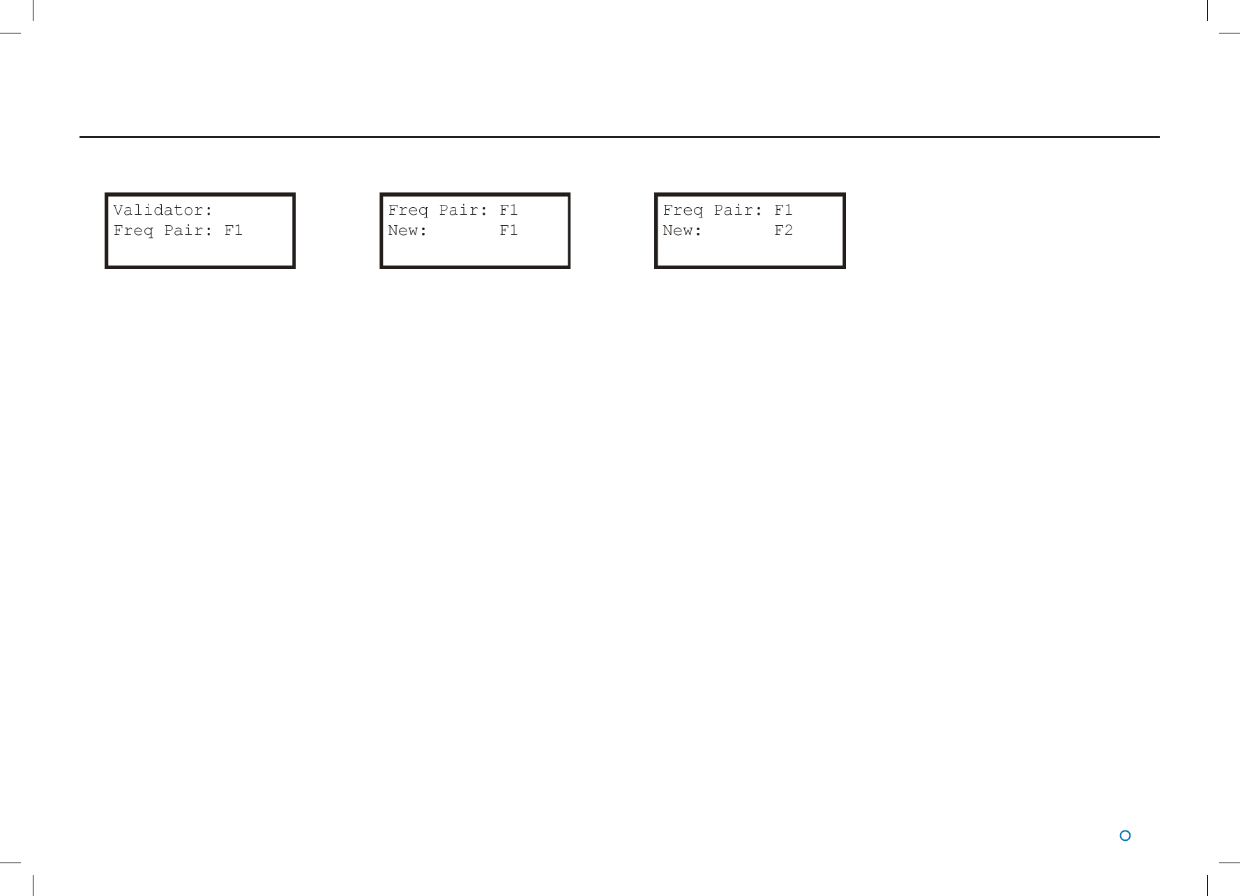
User Interface Layout(Continued)
Artemis Validator Frequency Pair
► ▲ Press ►to confirm your changes.

l 11
The purpose of the Artemis Validator is to test whether an Artemis sensor (Mobile Station) is
in working order.
This involves configuring the device to imitate a fixed station that the sensor under test
normally locks onto.
Conguration Procedure
1. Switch on the Artemis Validator.
2. Use the push button controls to navigate the menu system and set the Freq Pair and
Address to the same values as the Artemis unti that is being validated (see Modifying
Settings on page 7).
3. Optionally save the settings (see Saving Settings on page 9) for use next time.
Once the above steps have been carried out, the Artemis Validator can be used to test the
Artemis sensor
Validation Procedure
4. Place the Artemis Validator with a clear line of sight to the sensor at a distance of
between 10m and 300m.
5. Note the simulated range shown on the information display of the Artemis Validator.
6. Using the Artemis user interface aim the Artemis antenna towards the Artemis Validator.
7. Check that the range and bearing displayed are approximately correct (*see below).
8. For further validation, use the push button controls on the Artemis Validator to select a
different simulated range.
9. Repeat steps 7 and 8 as required.
*Note: the range displayed on the Artemis User interface may not exactly match the Range
as set on the Artemis Validator.
The Artemis sensor will report the sum of the Validator simulated range PLUS the actual
range to the Artemis Validator.
Operation
The reported range approximates R + S
where:
R is the true range between the sensor under test and the Artemis Validator.
S is the simulated range configured on the Artemis Validator.
So for example, if the true range is 100m and the Artemis Validator is set to a simulated
range of 1000m, the User Interface should show a range between 1095m and 1105m. If
the sensor under test cannot lock onto the Artemis Validator (step 6), or if the range and
bearing reported (step 7) are not reasonable values, then the Validation Procedure has
failed.
l 12
Rechargable Artemis Validator
Switch the unit off when not in use to preserve the battery.
!
The Artemis Validator is water resistant.
However, do not submerge the unit in water.
To Switch the Artemis Validator ON:
Press the ON/OFF button on the back of the unit.
Charging
The rechargeable Artemis Validator should be fully charged before
use. A full charge takes approximately 24 hours.
!DO NOT charge or use the Artemis Validator in an
explosive atmosphere or other hazardous environment.
The Artemis Validator will switch on whilst charging. It cannot be
turned off while charging.
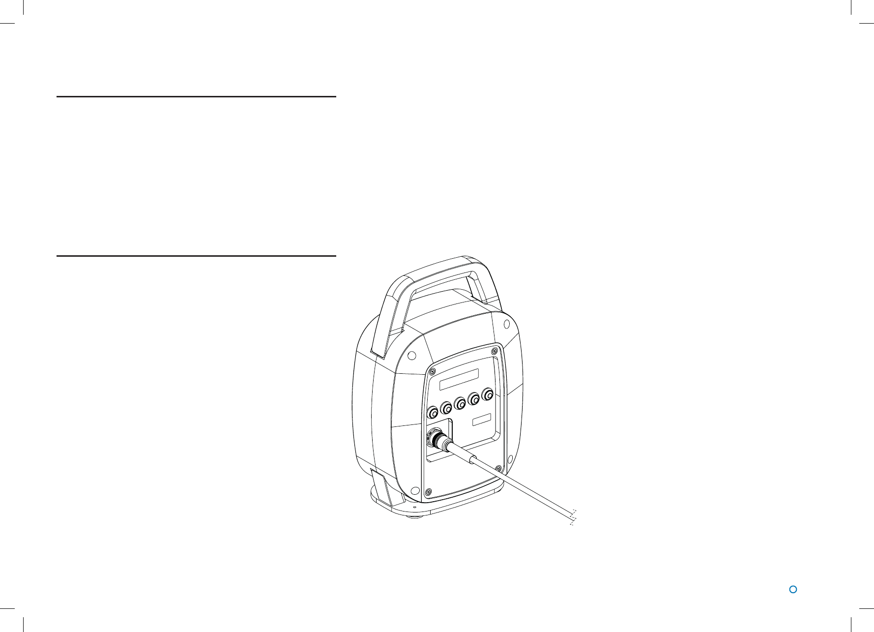
To Charge the Artemis Validator:
!Note: Only use the supplied charger. Only charge at
ambient temperatures of 0°C to +45°C.
1. Switch off the Artemis Validator and remove the plate on the
rear of the unit.
2. Connect the supplied mains charger (Part No. 21-0464; Input:
100–240VAC, 50–60Hz, 1.5A Output: 24VDC, 2.5A, 60W).
3. When charging is complete, disconnect the power from the unit
and place the rear plate back on.
!Do not open the Artemis Validator.
If you experience any problems with the unit, please contact:
Guidance Marine Ltd
5 Tiber Way
Meridian Business Park
Leicester Tel: +44 (0) 116 229 2600
LE19 1QP
United Kingdom Email: customerservices@guidance.eu.com
l 13
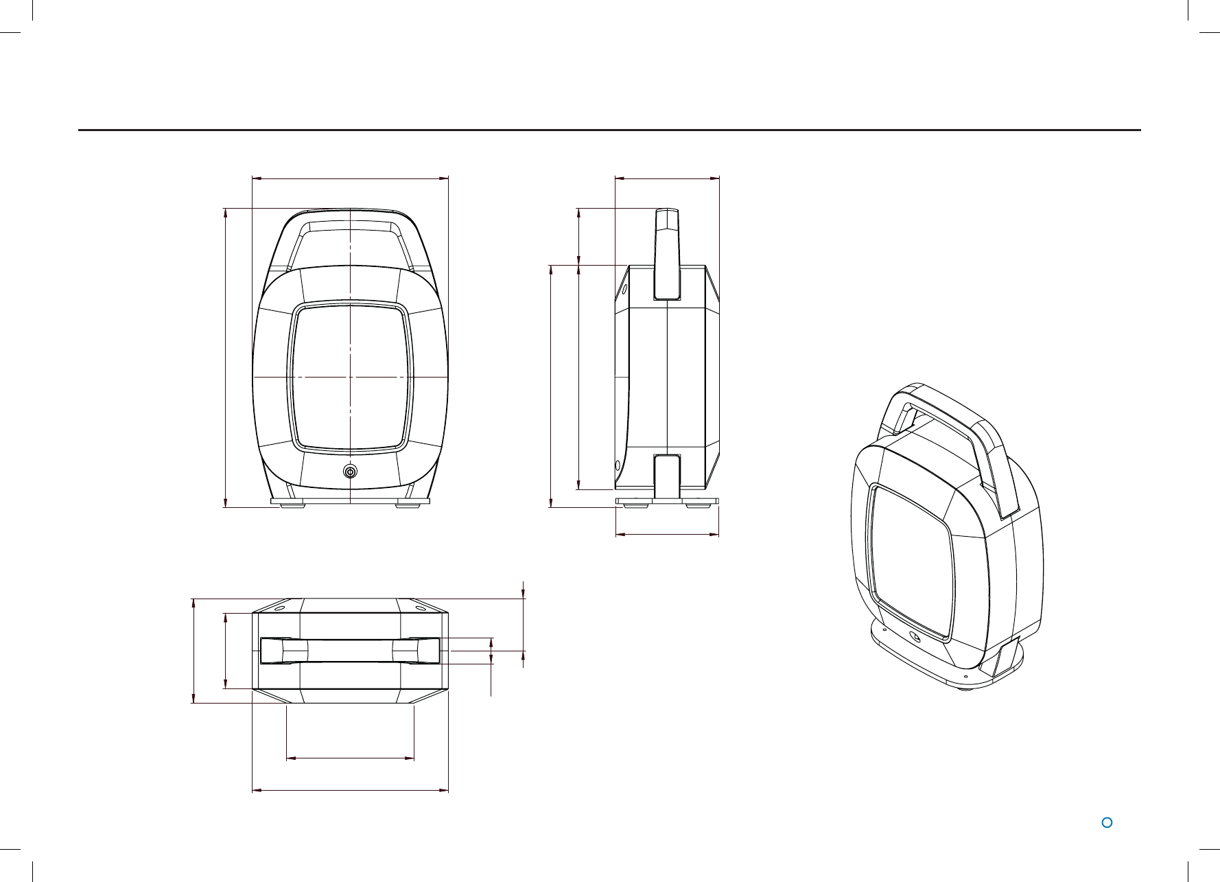
Dimensions
220.5
336.5
252
272.5
115.5
117.5
64
117.5
84.8
29
143.2
220.5
58.7
Diagram not to
scale. Dimensions
measured in mm.
Approx weight: 4.5 kg