LAVINA 25LMX USA Version 1 2016
2016-06-14
: Guide Lavina 25Lmx Usa Version 1 2016 LAVINA 25LMX USA version 1 2016 SUNBELT LAVINA X SERIES 2016 Lavina manuals Niagara-Library
Open the PDF directly: View PDF ![]() .
.
Page Count: 41
- WARRANTY AND RETURNS
- 1. GENERAL INFORMATION
- Manufacturer
- General Description
- Machine characteristics
- Main design
- Environmental Conditions
- Electrical Connection
- VACUUM CONNECTION
- TECHNICAL DATA
- VIBRATIONS
- SONOROUS EMISSIONS
- LABEL DATA
- CUSTOMER SERVICE
- 2. SAFETY INSTRUCTIONS
- Recommended Use
- Prohibited Use
- Preparation for work
- Protection Devices
- Arrest Functions
- Safe Use
- Residual Risks
- Before You Begin
- Operating Machine
- After Work is completed
- The Work Area
- Personal Protective
- Equipment (PPE)
- Operator
- 3. HANDLING AND TRANSPORTATION
- splitting the carriage from the mainhead
- LIFT THE MACHINE from working to tool mounting position
- Lifting
- Adjusting the handle
- Storage
- 4. OPERATION
- Preliminary Controls
- Water Flow Control Unit
- Adjusting and Mounting Tools
- The Control Board
- Starting the Machine
- Operating the Machine
- Stopping the Machine
- Alarm
- 5. TOOLS AND ACCESSORIES
- Weights
- Tool holder key
- Foam Plate
- Security plate for Quickchange pads
- 6. POPULAR TOOLS
- RECOMMENDED TOOLS
- Use Only Superabrasive’s Recommended Tools. For More Tooling Options, Visit www.superabrasive.com
- 7. MAINTENANCE AND INSPECTION
- Cleaning
- CHECK DAILY
- Check Every 200 Working Hours
- Check Every 400 Working Hours
- VACUUM
- WATER LEAKS
- MECHANICAL PARTS
- ELECTRICAL SYSTEM
- 8. TROUBLESHOOTING
- Index of Problems and Solutions
- 8.1 Replacing Power Cord and Plugs
- 8.2 DISMOUNTING AND MOUNTING TOOL HOLDER TO CHANGING V-RINGS AND FELT-RINGS
- 8.3 DISASSEMBLING AND MOUNTING TOOL HOLDER TO CHANGE BUFFERS AND ELASTIC ELEMENT
- 8.4 CORRECTING SAG OF THE USED PLANETARY CHAIN
- 8.5 Mounting new planetary CHAIN
- 8.6 Replacing the Planetary DRIVING Chain Wheel AND Planetary Tensioner
- 8.7 tensioning and replacing the belts
- 8.8 Replacing the Planetary driven Chain Wheel
- 8.9 replacing the pulley units
- 8.10 replacing the planetary unit
- 8.11 REPLACING PARTS FROM THE DRIVING OF THE CARRIAGE
- 8.12 Motor Connection
- 8.13 Fault diagnosis Inverter YASKAWA V1000
- 9. DISPOSAL
- 10. MANUFACTURER’S CONTACTS
- 11. SPARE PARTS
- ASSEMBLY AND PARTS SPECIFICATIONS
- 11. Lavina® 25LM-X Control Box Parts 200-240 Volt
- 12. Lavina® 25LMX-HV Control Box Parts 440-480 Volt
LAVINA® 25LM-X User Manual
Tech Support Line: 800-987-8403 | www.superabrasive.com | info@superabrasive.us
Superabrasive User Manual Original Language Lavina® 25LM-X / Lavina® 25LM-X-HV 1/2016
2
Superabrasive User Manual Original Language Lavina® 25LM-X / Lavina® 25LM-X-HV 1/2016
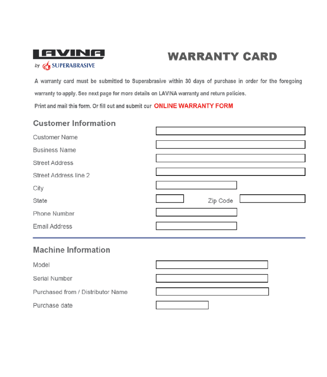
WARRANTY AND RETURNS
WARRANTY POLICY FOR LAVINA® X MACHINES
A warranty card must be submitted to Superabrasive within 30 days of purchase in order for the foregoing warranty to
apply.
You can either mail a hard copy of the warranty card or submit it electronically - see page 2.
Superabrasive warrants, from the time of delivery and receipt by the original customer, new and unused products
sold by
Superabrasive or Superabrasive-appointed distributors or dealers. Goods shall be free from defects in
materials and
workmanship. Superabrasive or a Superabrasive-appointed repair facility shall either replace or
repair any defects in the
Goods resulting from faulty design, materials, or workmanship. Products repaired or
replaced during the warranty period
shall be covered by the foregoing warranty for the remainder of the original
warranty period, or ninety (90) days from date
of the repair or shipment of the replacement, whichever is longer.
Spare parts for repair will be either new or equivalent to
new.
Warranty period shall be 2 years from the time of delivery and receipt by the original customer, or 600 operating
hours on
the machine - whichever occurs first. Superabrasive will cover the shipping charges for the transportation
of the machine to
Superabrasive (or an approved repair facility) and back to the customer (within the contiguous 48
United States) in the event
that the damage occurs and is reported within 200 operating hours. Shipping
charges, if
covered by Superabrasive, must be agreed upon in advance and approved by Superabrasive. Thereafter, the
customer will have to cover the shipping charges to Superabrasive and back. Superabrasive will not warranty
Goods after a
period of 2 years from the time of delivery and receipt by the original customer, or 600 operating
hours on the machine -
whichever occurs first.
Superabrasive shall not be liable for any defects that are caused by circumstances that occur after the Goods
have been
delivered and whilst the Goods are in the possession of the purchaser. Furthermore, the warranty
does not include normal
wear and tear or deterioration. Wear parts are not warranted. Superabrasive is not liable
for defects arising out of use of
non-OEM parts.
The Warranty is void if the purchaser has not followed the maintenance plan stipulated by the machine’s manual
and
warranty card. The warranty is void if the purchaser repairs said Goods himself, or if repairs are conducted by a
repair facility
that is not approved by Superabrasive. Superabrasive’s liability does not cover defects which are
caused by faulty
maintenance, incorrect operation, faulty repair by the purchaser, or by alterations conducted
without Superabrasive’s prior
written consent. The same applies to any alterations of the Goods or services
performed by another party other than
Superabrasive, a Superabrasive-appointed distributor, or a Superabrasive-
approved repair facility. The warranty is not
applicable on a defect that arises due to tools or parts that are not
original to Superabrasive. Replaced defective parts shall
be placed at Superabrasive’s disposal and shall become
property of Superabrasive. If such defective parts are replaced
within the warranty period, the shipping charges will be covered by Superabrasive. In warranty complaint cases,
when no
defects are found for which Superabrasive is liable, Superabrasive shall be entitled to compensation for
the labor, material
cost, and shipping charges, incurred by Superabrasive as as a result of the complaint.
The warranty herein is non-transferable, and only applies to the original owner or purchaser of the machine.
RETURN POLICY FOR LAVINA® X MACHINES
The Lavina® X machines may be returned, subject to the following terms:
In no case, a machine is to be returned to Superabrasive Inc. for credit or repair without prior authorization.
Please contact
Superabrasive Inc. or your local distributor for an authorization and issuance of a return
authorization number. This number
along with the serial number of the machine must be included on all packages
and correspondence. Machines returned
without prior authorization will remain property of the sender and
Superabrasive Inc. will not be responsible for them. No
machines will be credited after 90 days from the date of
invoice.
All returns must be shipped freight prepaid. Returned machines may be exchanged for other equipment or parts of
equal
dollar value. If machines are not exchanged, they are subject to a fifteen percent (15%) restocking fee.
3
Superabrasive User Manual Original Language Lavina® 25LM-X / Lavina® 25LM-X-HV 1/2016
WARRANTY AND RETURNS................................... 3
1. GENERAL INFORMATION .......................................... 5
Manufacturer .............................................................. 5
General Description ..................................................... 5
Machine characteristics ................................................ 5
Main design ................................................................ 5
Environmental Conditions ............................................ 5
Electrical Connection ................................................... 5
VACUUM CONNECTION ................................................ 6
TECHNICAL DATA ........................................................ 6
VIBRATIONS ................................................................ 6
SONOROUS EMISSIONS ............................................... 6
LABEL DATA ................................................................. 6
CUSTOMER SERVICE ..................................................... 6
2. SAFETY INSTRUCTIONS ............................................. 6
Recommended Use .................................................. 6
Prohibited Use ...................................................... 6
Preparation for work .................................................... 6
PROTECTION DEVICES ...................................... 7
Arrest Functions ...................................................... 7
Safe Use .............................................................. 7
Residual Risks ...................................................... 7
Before You Begin ..................................................... 7
Operating Machine .................................................. 7
After Work is completed .............................................. 7
The Work Area ..................................................... 7
Personal Protective .................................................. 7
Equipment (PPE) .......................................................... 7
Operator ............................................................ 7
3. HANDLING AND TRANSPORTATION ........................... 8
splitting the carriage from the mainhead ................... 8
LIFT THE MACHINE from working to tool mounting
position....................................................................... 8
Lifting ......................................................................... 8
Adjusting the handle .................................................... 8
Storage ....................................................................... 9
4. OPERATION ............................................................. 9
Preliminary Controls .................................................... 9
Water Flow Control Unit .............................................. 9
Adjusting and Mounting Tools ...................................... 9
The Control Board ...................................................... 10
Starting the Machine.................................................. 10
Operating the Machine .............................................. 10
Stopping the Machine ................................................ 11
ALARM ................................................................... 11
5. TOOLS AND ACCESSORIES ....................................... 12
Weights .................................................................... 12
Tool holder key .......................................................... 12
Foam Plate ................................................................ 12
Security plate for Quickchange pads ............................ 12
6. POPULAR TOOLS .................................................... 13
RECOMMENDED TOOLS ............................................. 13
Use Only Superabrasive’s Recommended Tools. For More
Tooling Options, Visit www.superabrasive.com ............ 13
7. MAINTENANCE AND INSPECTION ................... 14
Cleaning .................................................................... 14
CHECK DAILY ............................................................. 14
Check Every 200 Working Hours .................................. 14
Check Every 400 Working Hours .................................. 14
VACUUM ................................................................... 14
WATER LEAKS ............................................................. 14
MECHANICAL PARTS ................................................... 14
ELECTRICAL SYSTEM ................................................... 14
8. TROUBLESHOOTING ................................................ 21
Index of Problems and Solutions .................................. 21
8.1 Replacing Power Cord and Plugs ............................ 21
8.2 DISMOUNTING AND MOUNTING TOOL HOLDER TO
CHANGING V-RINGS AND FELT-RINGS .......................... 21
8.3 DISASSEMBLING AND MOUNTING TOOL HOLDER TO
CHANGE BUFFERS AND ELASTIC ELEMENT .................... 21
8.4 CORRECTING SAG OF THE USED PLANETARY CHAIN23
8.5 Mounting new planetary CHAIN ............................ 23
8.6 Replacing the Planetary DRIVING Chain Wheel AND
Planetary Tensioner .................................................... 24
8.7 tensioning and replacing the belts .......................... 25
8.8 Replacing the Planetary driven Chain Wheel ........... 27
8.9 replacing the pulley units ....................................... 27
8.10 replacing the planetary unit ................................. 28
8.11 REPLACING PARTS FROM THE DRIVING OF THE
CARRIAGE .................................................................. 28
8.12 Motor Connection ............................................... 28
8.13 Fault diagnosis Inverter YASKAWA V1000 ............. 29
9. DISPOSAL ............................................................... 31
10. MANUFACTURER’S CONTACTS ............................... 31
11. SPARE PARTS ........................................................ 32
ASSEMBLY AND PARTS SPECIFICATIONS ....................... 32
1. LAVINA®25LM-X General parts ............................... 32
2. LAVINA® 25LM-X Top Cover 1 parts ........................ 32
3. LAVINA®25LM-X Top Cover parts 2 .......................... 33
4. LAVINA®25LM-X Guard Parts .................................. 33
5. LAVINA® 25LM-X Bottom Cover 1 Parts ................... 33
6. LAVINA® 25LM-X Planetary Drive Parts .................... 34
6.1. LAVINA® 25LM-X Pulley Unit Assembly ............ 35
7. LAVINA® 25LM-X Bottom Cover 2 Parts ................... 35
8. LAVINA®25LM-X Water TANK Parts ......................... 36
9. LAVINA®25LM-X TOOL HOLDER PARTS/SEE
ALSO FIG.8.7.13/ .................................................... 36
(POS.1 INCLUDE POS.1.1;1.2;1.3/POS.1.3
INCLUDE POS.1.3.1 and etc.) ............................... 36
10. LAVINA®25LM-X CARRIAGE PARTS ........... 37
11. Lavina® 25LM-X Control Box Parts 200-240 Volt ...... 38
12. Lavina® 25LMX-HV Control Box Parts 440-480 Volt .. 40
4
Superabrasive User Manual Original Language Lavina® 25LM-X / Lavina® 25LM-X-HV 1/2016
1.GENERAL INFORMATION
This owner’s manual is intended for the operator of the Lavina® X machine, the servicing technician as well as for anyone
involved with operating or servicing the machine. We recommend that you read the instructions very carefully and follow them
strictly. The manual includes information about assembling, using, handling, adjusting and maintaining your Lavina® X floor
grinding and polishing machine.
MANUFACTURER
Superabrasive was founded in 1987, as a manufacturer of high quality diamond tools for the stone and concrete industry. Today,
Superabrasive is one of the world’s leading companies in the production of diamond tools and floor grinding machinery. At
Superabrasive, we strive to deliver the very best solutions to our customers, and enable them to work more efficiently.
GENERAL DESCRIPTION
The Lavina® X machine is intended for grinding, polishing and buffing concrete, marble, granite,
limestone, and terrazzo surfaces with diamond tools.
The Lavina® X machine is a three-disc machine, which can be used dry as well as wet.
For best results, use only tools manufactured or recommended by Superabrasive and its
distributors. Additionally, the machine could be used for grinding wood floor surfaces.
The Lavina® X machine is manufactured and fitted for the above-
mentioned applications only! Every other use may possess risks to the persons involved.
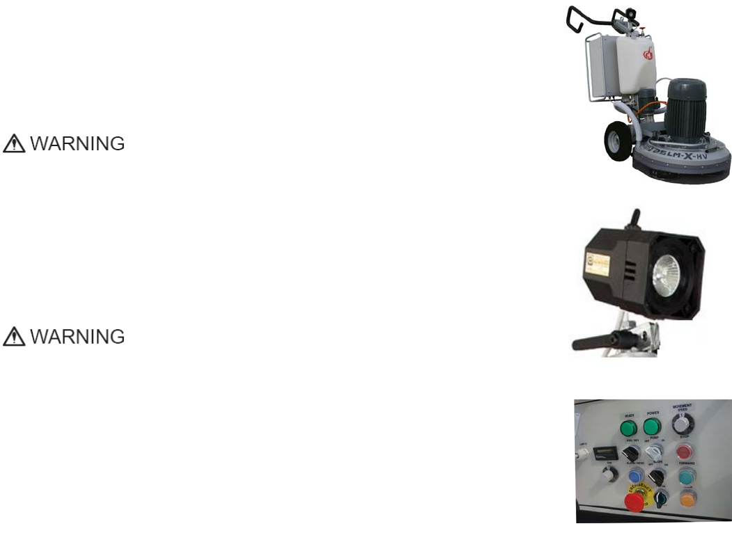
MAIN DESIGN
The two main component sections of each machine are: carriage and main head.
The handle (Fig.1.2) on the frame is adjustable in height and allows the operator to work in
a correct and safe working posture.
The halogen spotlight (Fig.1.2) enables the operator to work in darker
areas.
Existing lighting system does not replace adequate overhead lighting.
The controls are positioned on top of the electrical box (fig.1.3)
The electrical box (fig.1.3) contains the electric switching devices and the inverter.
The main feeding cable is connected with a plug and socket on top. The motor feeding cable is
plugged into the socket located on the bottom of the box.
The tank is on the opposite side of the frame, so that the weight of the
water has no influence on the operation of the machine. The frame weight, on the other hand, is
fully absorbed by the driving wheels. An electric pump sprays the water through a front sprayer
or internal.
The motor is mounted on the base plate and is driving the three heads with a belt system.
The planetary head is driven by a simplex roller chain .
ENVIRONMENTAL CONDITIONS
The temperature range for operating the Lavina® X machine outdoors is between 41°F and 86°F or 5°C and 30°C. Never use the
Lavina® X machine during rain or snow when working outdoors. When working indoors, always operate the machine in well-
ventilated areas.
ELECTRICAL CONNECTION
The voltage (Volt) and power (Ampere) are displayed on a label on the electrical control box to avoid any incorrect connection.
Refer to these before connecting the power. To avoid electrical shocks, make sure the ground power supply is functioning
properly.
Figure 1.2
Figure 1.3
Figure 1.1
5
Superabrasive User Manual Original Language Lavina® 25LM-X / Lavina® 25LM-X-HV 1/2016
VACUUM CONNECTION
A connection for a vacuum dust extractor is located on the carriage. The Lavina® X machine does not include a vacuum dust
extractor. The customer must purchase the vacuum dust extractor separately. The hose of the vacuum extractor must be Ø 50
mm and can be glided over the pipe. The vacuum dust extractor must be adapted for floor grinders and have a minimum air
displacement of 320m3/h with a negative vacuum of 21 kPa.
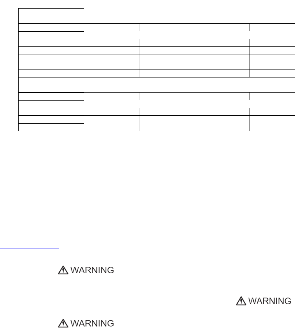
TECHNICAL DATA
VIBRATIONS
The vibrations of the machine are within the limits of directives and harmonized standards from the European Union when the
Lavina® X is operated with the recommended tools and in normal conditions.
SONOROUS EMISSIONS
The sonorous emissions are within the limits of directives and harmonized standards from the European Union when the
Lavina®X is operated with the recommended tools and in normal conditions. However, as previously stated, the operator must
wear ear protectors.
LABEL DATA
The data on the label provides the correct Voltage and kW (needed for operational purposes);
Weight (needed for transportation purposes); production year and serial number (needed for maintenance purposes).
CUSTOMER SERVICE
For customer assistance and technical support call your local distributor or call Superabrasive Inc. at 1-800-987-8403 or visit us at:
www.superabrasive.com
, where you can download a copy of this manual.
2. SAFETY INSTRUCTIONS
RECOMMENDED USE
The Lavina® X machine is designed and manufactured to grind and
polish concrete, terrazzo, and natural stone floors. It can be used
for renovation as well as for polishing. The machine is designed for
dry or wet use. When using it dry, use a vacuum of appropriate size.
For more information, please refer to the chapter on handling the
vacuum connection.
PROHIBITED USE
The machine MUST NOT be used:
•For applications different from the ones stated in the general
description chapter.
•For non-suitable materials. In environments which:
-Possess risks of explosion,
-Possess high concentration of powders or oil substances in
the air,
-Possess risks of fire Feature inclement conditions,
-Possess electromagnetic radiation.
PREPARATION FOR WORK
Make sure that:
•You have closed the work area, so that no person unfamiliar
with operating the machine can enter the area.
•The tool plate and tools are adjusted to the machine
properly.
•There are no missing parts of the machine
•The machine is in upright working position.
•The protection devices are working properly.
•The electrical cable is free to move and follow the machine
Lavina® 25LM-X
Lavina® 25LM-X-HV
Voltage/Hz
3 ph x 200-240V/50-60Hz
3 ph x 440-480V/50-60Hz
Amperage
Max 45 Amps
Max 30 Amps
Power
11 kW
15 HP
11 kW
15 HP
Tool holder rpm
300-1100 rpm
300-1100 rpm
Working width
655 mm
655 mm
655 mm
25.8”
Tool diameter (QC Plate)
3x 225 mm
3x 225 mm
3x 225 mm
3x 9”
Weight
349 kg
349 kg
349 kg
769lbs
Grinding pressure
180 kg
180 kg
180 kg
397 lbs
Additional weight
max 2x 29 kg
max 2x 29 kg
max 2x 29 kg
max 2x 64 lbs
Application
wet and dry
wet and dry
Vacuum hose port
Yes
Yes
Water tank capacity
20 l
20 l
20 l
5.2 gal
Water feed
with pump (peripheral and front)
with pump (peripheral and front)
Cable length
17.4 m
17.4 m
17.4 m
57 ft
Machine LxWxH
1800x690x1265 mm
1800x690x1265 mm
1800x690x1265 mm
71x27.2x50”
Packing Crate LxWxH
1480x820x1560 mm
1480x820x1560 mm
1480x820x1560 mm
58.3x32.3x61.5”
6

Superabrasive User Manual Original Language Lavina® 25LM-X / Lavina® 25LM-X-HV 1/2016
easily.
•In order to keep the electrical cable from being damaged, no
vehicle should cross the zone where electrical cables are
situated.
PROTECTION DEVICES
The machine is equipped with several protection devices
including the following:
•An emergency stop button
•A protection skirt and a hood for protecting the tool plates.
These devices protect the operator and/or others persons from
potential injuries. Do not remove them. Before using the machine,
please ensure that all protection devices are mounted and
function properly. The Security plate prevents the QuickChange
pads to from loosening during work
ARREST FUNCTIONS
Functions of arresting of the machine are following:
•Button to stop the motor (category 1)
•Emergency button (category 1)
SAFE USE
The Lavina® X is designed to eliminate all risks correlated with its
use. However, it is not possible to eliminate the risks of an eventual
accident with the machine. Unskilled or uninstructed operator may
cause correlated residual risks. Such risks are:
•Position Risks: due to operator’s incorrect working position
•Tangling up Risks: due to wearing inappropriate working
clothes
•Training Risks: due to lack of operational training.
NOTE: : In order to reduce all consequences of the above-
mentioned risks, we advise that machine operators will follow
the instructions in the manual at all times.
RESIDUAL RISKS
During the normal operating and maintenance cycles, the operator
is exposed to few residual risks, which cannot be eliminated due to
the nature of the operations.
BEFORE YOU BEGIN
•Working area must be clear from any debris or objects.
•A first-time operator must always read the manual and pay
attention to all safety instructions.
•All electric connections and cables must be inspected for
potential damages.
•Ground wire system of the power supply must be also
inspected.
•Perform general daily inspections of the machine and inspect
the machine before each use.
•Always inspect the safety devices: Mount the Security plate for
the QuickChange pads.
•The emergency break must be clear and working
•The tool protector must be working
•The machine must be clean
•Never operate the machine in the rain!
•Confirm that there are no missing parts especially after
transportation, repair or maintenance.
•Before filling the water tank with water make sure
the machine is not working and the main switch is
turned off.
•Before turning on the machine make sure that the base is
placed on the floor, the machine MUST NOT be in an upright
position when turned on!
OPERATING MACHINE
When operating the Lavina® X, make certain that there is no
one, but you around the machine.
Never leave the machine unattended while working.
The electrical cable must move freely and must be damage-
free.
The water hose must move
freely and must be damage-free. Check to make sure the
floor, you are preparing to work on, is even. If the floor is
uneven, it may damage the machine.
AFTER WORK IS COMPLETED
•Clean the machine and its surroundings properly
•Empty and clean the water tank
•Unplug the machine and wind up the electrical cable
•Store the machine in a safe place
THE WORK AREA
•Make certain that people or vehicles do not enter the work
area.
•Avoid cables and hoses being in the way.
•Always check the floor for debris
PERSONAL PROTECTIVE
EQUIPMENT (PPE)
•Always wear safety shoes when working with the machine.
•Always wear ear protectors when working with the
machine.
•All personnel in the immediate work area must wear safety
glasses with side shields.
•Always wear safety gloves when changing the tools.
•Always wear clothes suitable for the work environment.
OPERATOR
The Lavina® X machine.
The operator must know the machine’s work environment.
Only one operator at a time can work with the machine.
The operator must be properly trained and well instructed
prior operating the machine.
•The operator must understand all the instructions in this
manual.
•The operator must understand and interpret all the drawings
and designs in manual.
•The operator must know all sanitation and safety regulations
pertaining to the operation of
•The operator must have floor grinding experience.
•The operator must know what to do in case of emergency.
•The operator must have an adequate technical knowledge
and preparation.
7
Superabrasive User Manual Original Language Lavina® 25LM-X / Lavina® 25LM-X-HV 1/2016
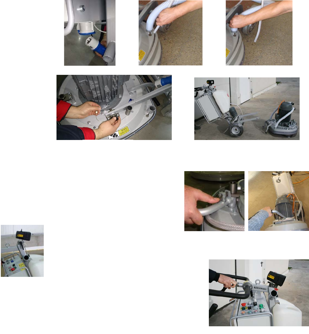
3. HANDLING AND TRANSPORTATION
SPLITTING THE CARRIAGE FROM THE MAINHEAD
Unplug the motor
cable plug from the
control box and
disconnect the water
hose from the main
head by pulling it out
(Fig.3.1) (Fig.3.2).
Wind the electrical
cable on the carriage.
Release the pin sets
which attach the
head to the
carriage(Fig.3.4). Pull
out the vacuum
hoses (Fig.3.3), and
dismount the head
from the
carriage(Fig.3.5).
The head of the
LAVINA® X machine
has one bar for
support and is used as
handles for easy moving and transportation.
LIFT THE MACHINE FROM WORKING TO TOOL MOUNTING POSITION
Push the lock the handle down and swivel it to thefront (Fig.3.6.1). Pull the
handle up and ensure the head is a stable upright position, for
mounting/dismounting the tool. Ensure that the water tank is empty before
flipping the machine. Pull the head in upright position (Fig.3.6.2).
LIFTING
Lifting the machine by crane is possible with the eye bolt, which is mounted
on the carriage (see Fig. 3.7). The eye bolt and
machine construction is rated only for the
weight of the machine. Do not list any other
leads on the machine. Always use hoisting equipment rated for 300 kg or 660 lbs.
ADJUSTING THE HANDLE
The Handle on the frame is adjustable in height and allows the operator to work in a
correct and safe posture. The unlocking is by pulling the handle ( fig.3.8)The locking is
automatically under action of the spring. Choose the upright position to move easy
the machine.
Figure 3.6.1
Figure 3.6.2
Figure 3.7
Figure 3.4
Figure 3.1
Figure 3.2
Figure 3.3
Figure 3.5
Figure 3.8
8
Superabrasive User Manual Original Language Lavina® 25LM-X / Lavina® 25LM-X-HV 1/2016
STORAGE
Always store and transport the Lavina® X
machine in a dry place. Never transport the
Lavina® X machine unprotected; it may be
damaged if transported unprotected during
rain or snow.
When storing the machine the temperature may fall down to or to less than 32F (or 0o C) you should empty the water from the
system using the following steps:
- Pull out the hose of the tank (Fig.3.9)
-Using compressed air blow out the water from the system for the two positions of the turn-cock (Fig. 3.10, Fig. 3.11).
4. OPERATION
PRELIMINARY CONTROLS
Inspect the working area as explained in the safety instructions. For wet use, fill the water tank when the electrical cable is
disconnected. Connect the vacuum extractor and ensure that the vacuum hose is clear and that it will easily follow the machine. Plug
in the machine and make sure that the power cord is free to follow the direction of the working Lavina® X machine.
WATER FLOW CONTROL UNIT
The operator can choose the water sprayer in the
front when the tap is in the horizontal position
(Fig.4.1), the water will spray under the cover of the
machine when the level is in the vertical position
(Fig.4.2).The flow regulating valve located on the
tank (Fig.4.3) is increasing or reducing the water
flow to the
working
area – in front of the machine
or under the main head cover of the
machine.
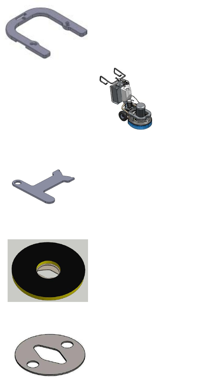
ADJUSTING AND MOUNTING TOOLS
The Holder A41 in LAVINA® X can work with either 3 or 6 buffers
which will change its elasticity. You can make the change after
dismounting the holder as per the instruction in
TROUBLESHOOTING. In Lavina 25L-X the holder is initially
mounted with 6 buffers.
Mount the tools only after ensuring that there is enough
diamond bond material left. Be sure that the plates are always
clean before mounting. WARNING: Always secure the “QuickChange” pads with the security plate (Fig.4.4), lock with the tool holder
key (Fig.5.3). Diamond tools with Velcro are attached to three 9inch foam plates (Fig.4.5). The foam plates are mounted on the key
lock (butterfly). Always use the tool holder key (Fig.5.3).
Figure 3.9
Figure 3.10
Figure 3.11
Figure 4.5
Figure 4.4
Figure 4.2
Figure 4.3
Figure 4.1
9
Superabrasive User Manual Original Language Lavina® 25LM-X / Lavina® 25LM-X-HV 1/2016
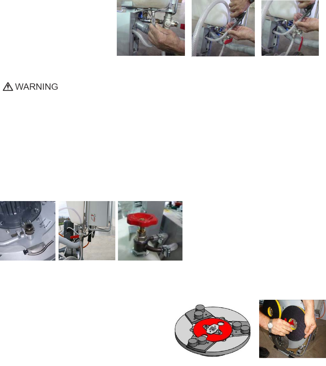
THE CONTROL BOARD
1. Power cable plug
2. Lamp cable gland
3. Digital RPM indicator Indicates the revolution per minute of the grinding plates (not the
revolution per minute of the entire
4. READY led lights green when the power is on
5. Forward/Reverse switch choose forward for clockwise rotation of the grinding plates
or reverse for anti-clockwise rotation of the grinding plates (Recommended ) Preferred
operating direction is when the switch is on position F. The proper direction of rotation
of the motor (anti-clockwise) is indicated by arrow on its cover.
6. Power led lights green when the power is on
7. Water pump switch Lights orange when the water pump is working.
8. Potentiometer changes the speed of the movement forward or back.
9. STOP button stops the movement forward or back, by switching off the connection
between gearmotor and wheels of the carriage. By activating it you can operate the machine in manual mode.
10. FORWARD button set direction forward. Lights green when is on.
11. BACK button set direction backward. Lights red when is on.
12. ON/OFF switch SLOPE In position ON, does not allow to switch off the connection between
the gearmotor and the wheels of the carriage, bothe from the STOP button /pos.9/, and from the Emergency stop button. It
must be used when operating the machine on a slope for the security of the operator and the machine. Disconnecting the
connection between the gearmotor and the carriage wheels is possible after switching the button in position OFF and activating
the button STOP /pos9/.
13. READY OFF / ON switch. Turning ON the switch, it lights showing that the machine is in standby mode. Turning OFF the switch, it
lights off showing the machine is out of standby mode. After releasing the switch it goes back in central position.
14. Emergency button used in Emergency situations for stopping the motor.
15. ALARM/Reset button resets the alarm of the inverter. Button lights blue when the inverter goes into alarm mode
16. Potentiometer changes the RPM of the grinding plates from 300-1100 rpm
STARTING THE MACHINE
Follow strictly the instructions in chapter "SAFETY INSTRUCTOINS".
NEVER WORK WITH THE MACHINE WITHOUT VISUAL CONTACT WITH IT.
First, follow the directions in chapter Safety Devices and Safety Instructions. If working wet, add water to the floor
surface. If working dry, omit this step, and instead, switch on the vacuum unit. Next, pull the emergency stop (Fig.4.6-14)
to ensure that the machine is in working condition. Check the potentiometer (Fig.4.6-16) and ensure that it is set at the
working speed. Check the potentiometer (Fig.4.6-8) for the required working speed.
Finally, hold the machine firmly and turn the start button (Fig.4.6-6) and set movement direction of the machine – forward
or backward from the corresponding buttons (Fig.4.6-10 and Fig.4.6-11).
OPERATING THE MACHINE
Guide the machine in straight lines across the floor, and with each new line overlap a little bit of the previously completed
surface.
At the end of each line you can reverse the direction of the machine by simply pressing the corresponding button
FORWARD or BACK and through the handles to direct a new runway. If you get tight the handles and trigger the button
STOP you will get to manual operated mode of the machine and can performe more complicated maneuvers. Once you
direct the machine in the desired direction activate again the selfpropelled movement. Increase or decrease of the speed
of the machine when operating can be made by the potentiometer (Fig.4.6-8)
Figure 4.6
10
Superabrasive User Manual Original Language Lavina® 25LM-X / Lavina® 25LM-X-HV 1/2016
Work at a constant speed allowing the tools time to work at a speed appropriate for the tools’ grit size. Avoid
vibrations. Do not stop the Lavina® 25LM-X-HV machine in one spot while the tools are still working because they will
leave marks on the floor surface. When working wet, preliminary chose with the water tap (Fig.4.2) the position for water
feed and periodically start the pump (Fig 4.6-7) to release water onto the floor surface. When working dry, check the floor
surface periodically to ensure that dust is not accumulating on the surface, also check regularly if your vacuum works
properly.
If you need to process on the floor with a slope that requires significant effort to work with machine with manual
control, put the button SLOPE in position ON. In this position the activating the button STOP or Emergency stop will not
disconnect wheels and motorgear connection and it will serve as a break on any movement of the machine on the slope.
In that case the machine is operated by the buttons FORWARD ; BACK and STOP, but without possibility to go to
manual control and at the end of the coarse. To switch to manual operation and control of the machine get the button
SLOPE in position OFF and push the button STOP.
STOPPING THE MACHINE
The stopping of the machine must be done gradually until the motor stops. Do not stop moving the machine before
arresting the motor as the tools could damage the surface. To stop switch the off switch (Fig.4.6-15). Use the Emergency
button (Fig.4.6-14) only in emergency or use it to switch the power totally off.
Remember not to hold the machine in one spot before turning off the motor.
The machine drive is stopped by the button STOP (Fig.4.6-9) or Emergency button (Fig.4.6-14)
ALARM
The Alarm light ((Fig.4.6-15) will light incase inverter goes in alarm mode. The most common failure is motor in
overload. To reset the mode push reset button ((Fig.4.6-15).
11
Superabrasive User Manual Original Language Lavina® 25LM-X / Lavina® 25LM-X-HV 1/2016
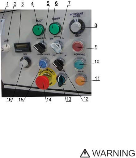
5. TOOLS AND ACCESSORIES
WEIGHTS
Superabrasive offers additional weights for increasing the productivity of the machine (Fig.5.1).
Each additional weight weighs about 64 lbs or 29kg. Each individual application, type and
condition of surface, power capacity of the outlet, etc. will determine the number of weights
you can use without tripping a breaker. The weight stacks onto three posts that are around the
outer bowl (Fig.5.2). The additional weights depend on the tools; it is not always possible to ass
weights. Some tools work too aggressively and the machine can stop. The weight can be
ordered with item number A08.00.00.00
TOOL HOLDER KEY
The tool holder key (Fig.5.3) is used for adjusting, mounting and dismounting of the foam plates.
Always use the key for mounting.
Item number is A03.00.00.00
FOAM PLATE
Diamond tools with Velcro are mounted on the foam plate 9“(Fig.5.4). The foam plate is
mounted on the “QuickChange”System.
Item number is LV-9-FP-S
SECURITY PLATE FOR QUICKCHANGE PADS
Plate (Fig.5.5) used to ensure the “QuickChange”
pads. Item number is A38.00.01
Figure 5.3
Figure 5.1
Figure 5.4
Figure 5.5
Figure 5.2
12
Superabrasive User Manual Original Language Lavina® 25LM-X / Lavina® 25LM-X-HV 1/2016
6. POPULAR TOOLS
RECOMMENDED TOOLS
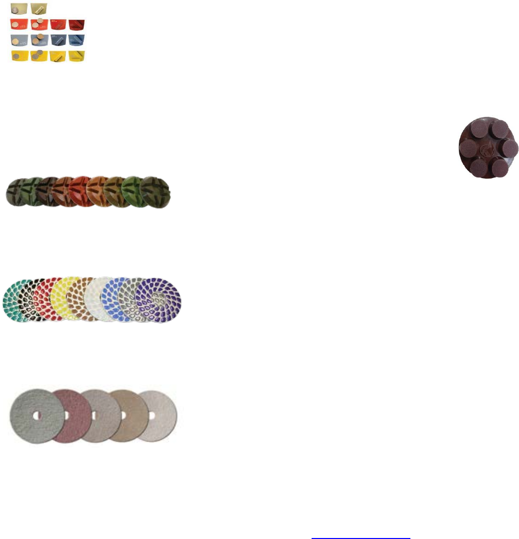
QuickChange Metal Bond Tools feature extremely fast and convenient tool changes, and a long tool
life, providing for great long-term cost savings. The QuickChange pads are produced in four
different
bonds for super hard, hard, medium and soft concrete, in a full range of grit sizes (from 6 to
120 grit). They are offered with 1 or 2 buttons or rectangular segments, which allows you to
customize the aggressiveness of the cut.
Calibra grinding discs: our popular ceramic bond discs are designed for the removal of difficult scratches
and they save you valuable time by eliminating the need for multiple passes with metal tools. They can be
used
wet or dry, and are best for hard concrete applications.
They are 3-inch, with included Velcro back attachment.
NATO® polishing discs feature a special resin formula designed for both wet and dry applications and a unique design with
wide channels allowing for work on a cleaner surface and ensuring a quality polish. Available in 3 and 4 in sizes. They are with
included Velcro attachment.
V-HARR® Premium Polishing Pads are designed for mechanically polishing and restoring concrete; also ideal for terrazzo and
hard stone floors. V-HARR® pads are offered in a wide variety of diameters and grit sizes to accommodate many applications.
Dry use is strongly recommended.
Shine Pro® are high quality diamond-impregnated pads for floor maintenance. Available in a variety of sizes, and are great for
daily use. When used wet, they require only water (no wax or chemicals needed) and are a very environmentally friendly solution
for maintaining floors.
Use Only Superabrasive’s Recommended Tools. For More Tooling Options, Visit www.superabrasive.com
13
Superabrasive User Manual Original Language Lavina® 25LM-X / Lavina® 25LM-X-HV 1/2016
7. MAINTENANCE AND INSPECTION
CLEANING
Keep your machine clean. Cleaning the machine in a regular basis will help detect and solve potential problems before they can
cause damage to the machine. Most importantly, check and clean the tool plate connections, power cords, plugs, vacuum hoses,
and water tank.
CHECK DAILY
After operating the Lavina®X machine, the operator should conduct a visual inspection of the
machine. Any defect should be solved immediately. Pay attention to power cords, plugs, vacuum
hoses, loose bolts or screws.
Tool holders: Buffers and elastic element are consumables and must be visually checked on a daily
basis and replaced if necessary. Make sure the flanges or discs are securely locked in place. The key
lock holders (butterflies) should also be checked.
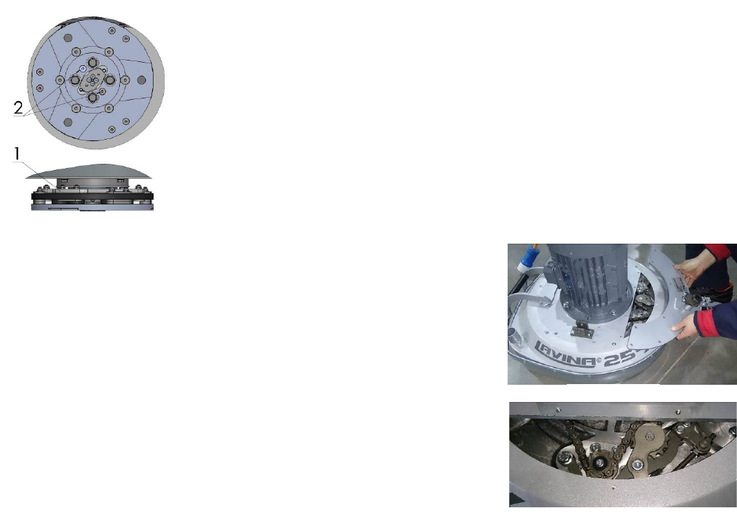
Check the rubber buffers and make sure the holders are secure. The flange holding the buffers
(Fig.7.1-1) has to be firmly secured to the unit. If there is a gap seen here, that means the screws
securing the holder are loose. The screws have to be tightened immediately to safely operate the
machine. Working with loose screws could cause serious damage to the machine. The tightening
force of the screws has to be 22-25N.m (16-18ft/lbs).
It is very important to regularly check the screws that secure the “QuickChange” holder to the safety
part (Fig.7.1- 2), so that the holder will not fly away if the buffers get damaged. The “QuickChange”
should be clean also.
CHECK EVERY 200 WORKING HOURS
Every 200 working hours, the operator should inspect all parts of the machine
carefully. Most importantly, inspect and clean the tool plate connections, power cord
plugs, vacuum hoses and water tank and filter. Also, check the water flow of the pump.
Check the guard assembly. Make certain the wheels are clean and rotate properly.
Inspect the control buttons. If there are defective control parts, they should be
replaced immediately. Replace worn vacuum and water hoses.
Open the service cover on the motor base (Fig 7.2) (Fig 7.3) to check of the
planetary chain. Lubricate the chain with special lubricant for chains and correct the
sag if needed. For sagging correction (See TROUBLESHOOTING 8.4 ).
Dismount the tool holders (See TROUBLESHOOTING) and replace all parts
(elastic element, buffers, sealer caps, “O” rings) that have the slightest damage.
CHECK EVERY 400 WORKING HOURS
Besides the checks of 200 working hours, replace sealer and V-rings like described in chapter “TROUBLESHOOTING DISMOUNTING
TOOL HOLDERS TO CHANGING V-RINGS AND FELT-RINGS.
VACUUM
As stated previously, frequently check hoses and other parts for clogging.
WATER LEAKS
Leaking parts should be replaced immediately because the water could damage your machine.
MECHANICAL PARTS
Parts such as the belts, seal rings, cap rings, spiders, buffers and guard assembly are subject to wear and must be replaced as needed.
ELECTRICAL SYSTEM
Dust should not enter the control box, as it will destroy the controls. Remove (blow out) any dust present
Figure 7.3
Figure 7.2
Figure 7.1
14
Superabrasive User Manual Original Language Lavina® 25LM-X / Lavina® 25LM-X-HV 1/2016
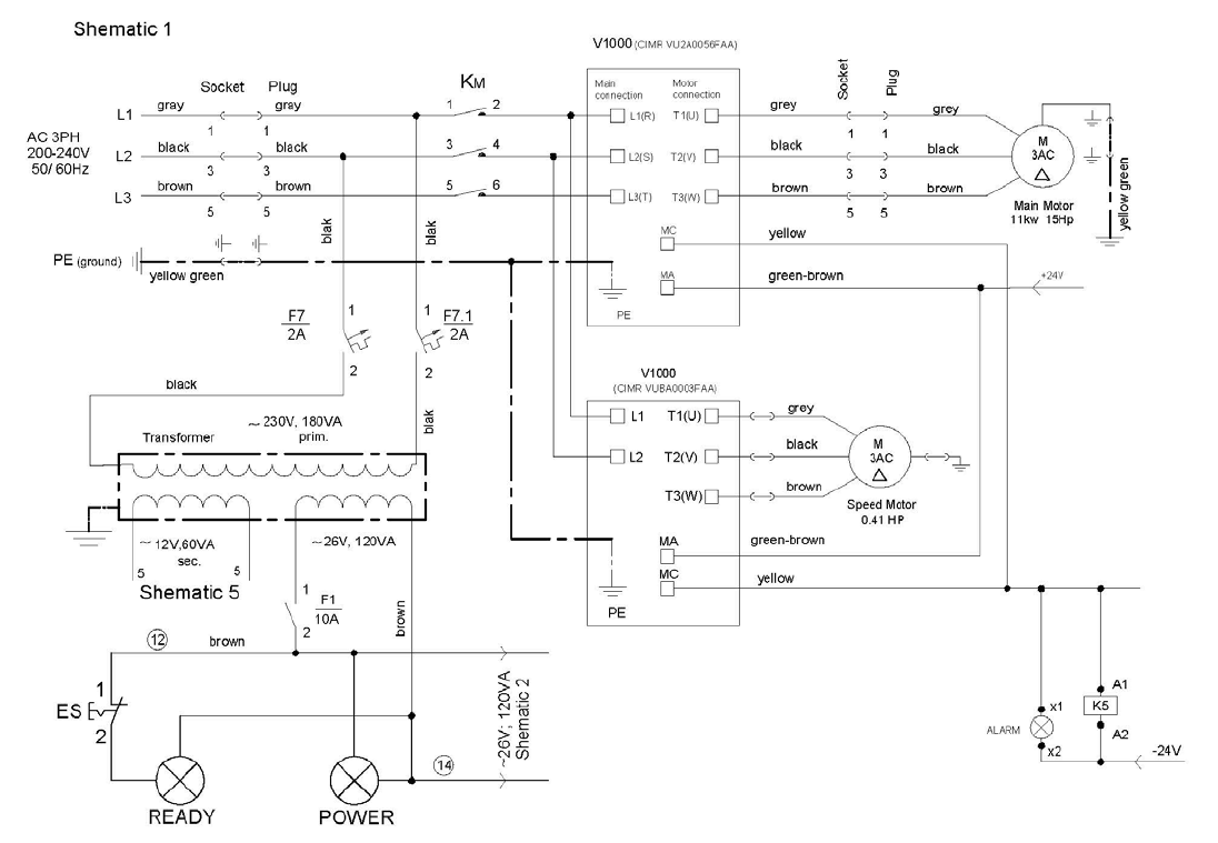
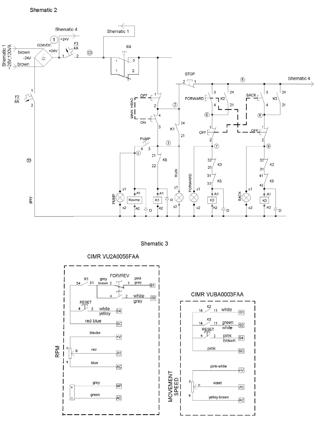
Lavina® 25LM-X Electrical schemes with Yaskawa Inverter 200-240 VOLT
15
Superabrasive User Manual Original Language Lavina® 25LM-X / Lavina® 25LM-X-HV 1/2016
16
Superabrasive User Manual Original Language Lavina® 25LM-X / Lavina® 25LM-X-HV 1/2016
17
Superabrasive User Manual Original Language Lavina® 25LM-X / Lavina® 25LM-X-HV 1/2016
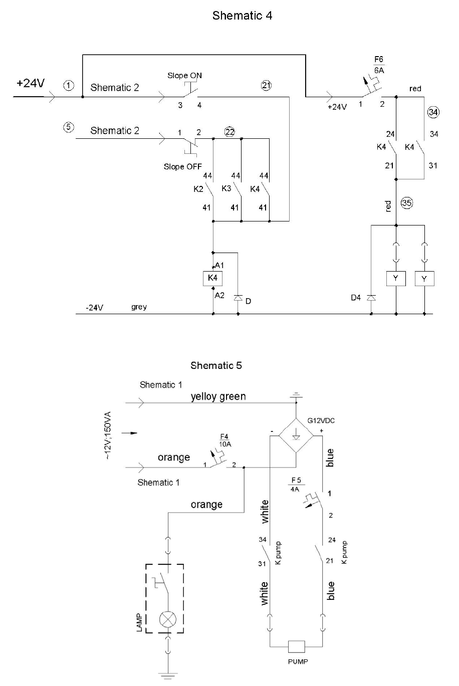
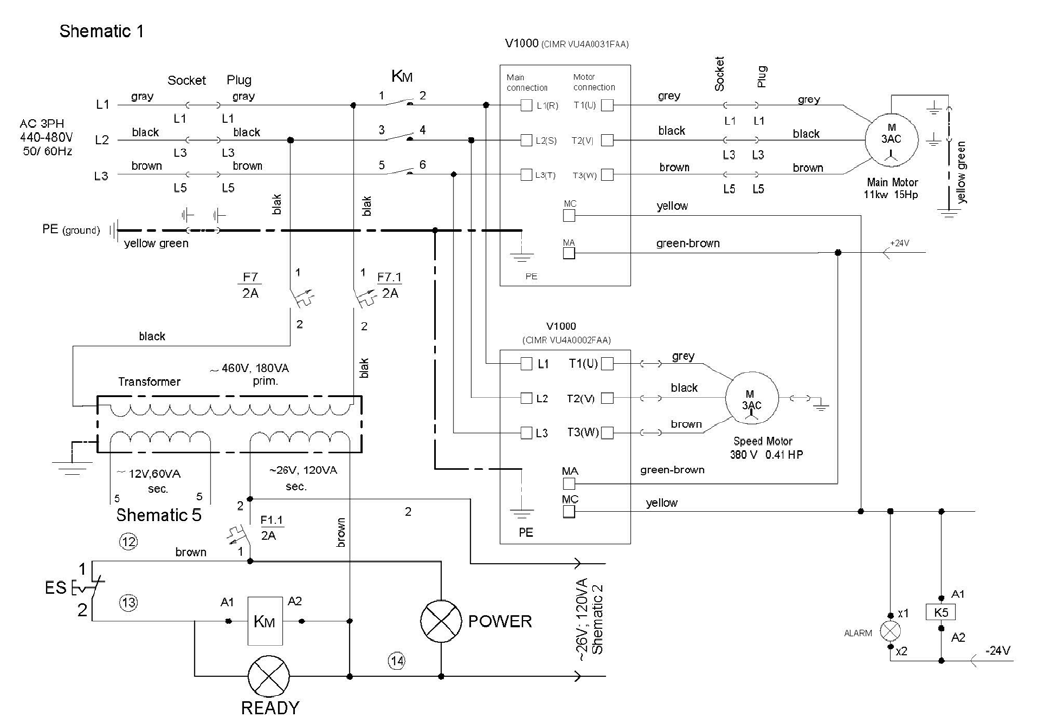
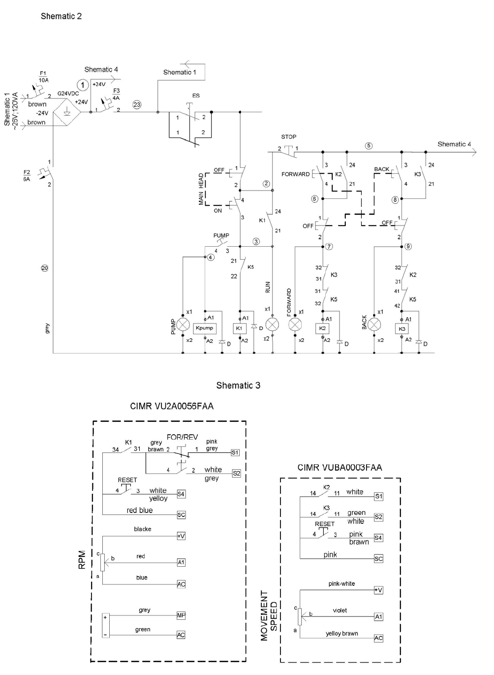
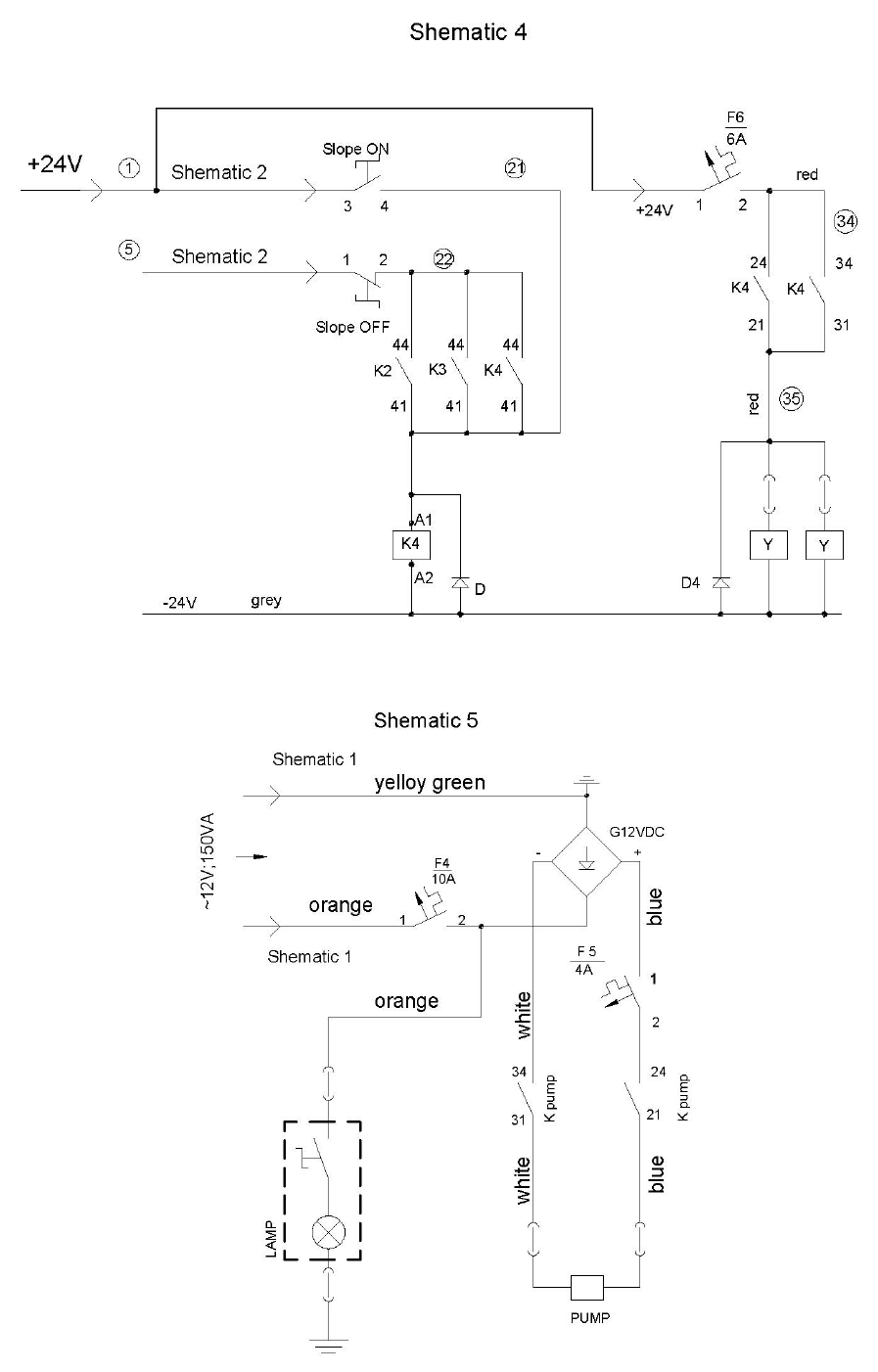
Lavina® 25LM-X-HV Electrical schemes with Yaskawa Inverter 440-480 VOLT
Figure 7.4 /scheme 1/
18
Superabrasive User Manual Original Language Lavina® 25LM-X / Lavina® 25LM-X-HV 1/2016
19
Superabrasive User Manual Original Language Lavina® 25LM-X / Lavina® 25LM-X-HV 1/2016
20

Superabrasive User Manual Original Language Lavina® 25LM-X / Lavina® 25LM-X-HV 1/2016
8. TROUBLESHOOTING
INDEX OF PROBLEMS AND SOLUTIONS
8.1 REPLACING POWER CORD AND PLUGS
When replacing the power cord or plugs always use cords and plugs with the same specifications as the original ones.
Never use lower quality or different types of cords and plugs.
In addition, take into consideration the distance between the appliance and the electrical source. The greater the distance, the greater
the resistance and the less current that will be available at the other end, there will be a voltage drop and the inverter will sign into
alarm mode. This will also happen if several machines are working on the same line or when the generator is underrated. In general,
our standard power cable can be doubled in length; if you need longer lengths then you must replace all the cables with cables of a
bigger gauge rate for the length and amperage.
8.2 DISMOUNTING AND MOUNTING TOOL HOLDER TO CHANGING V-RINGS AND FELT-RINGS
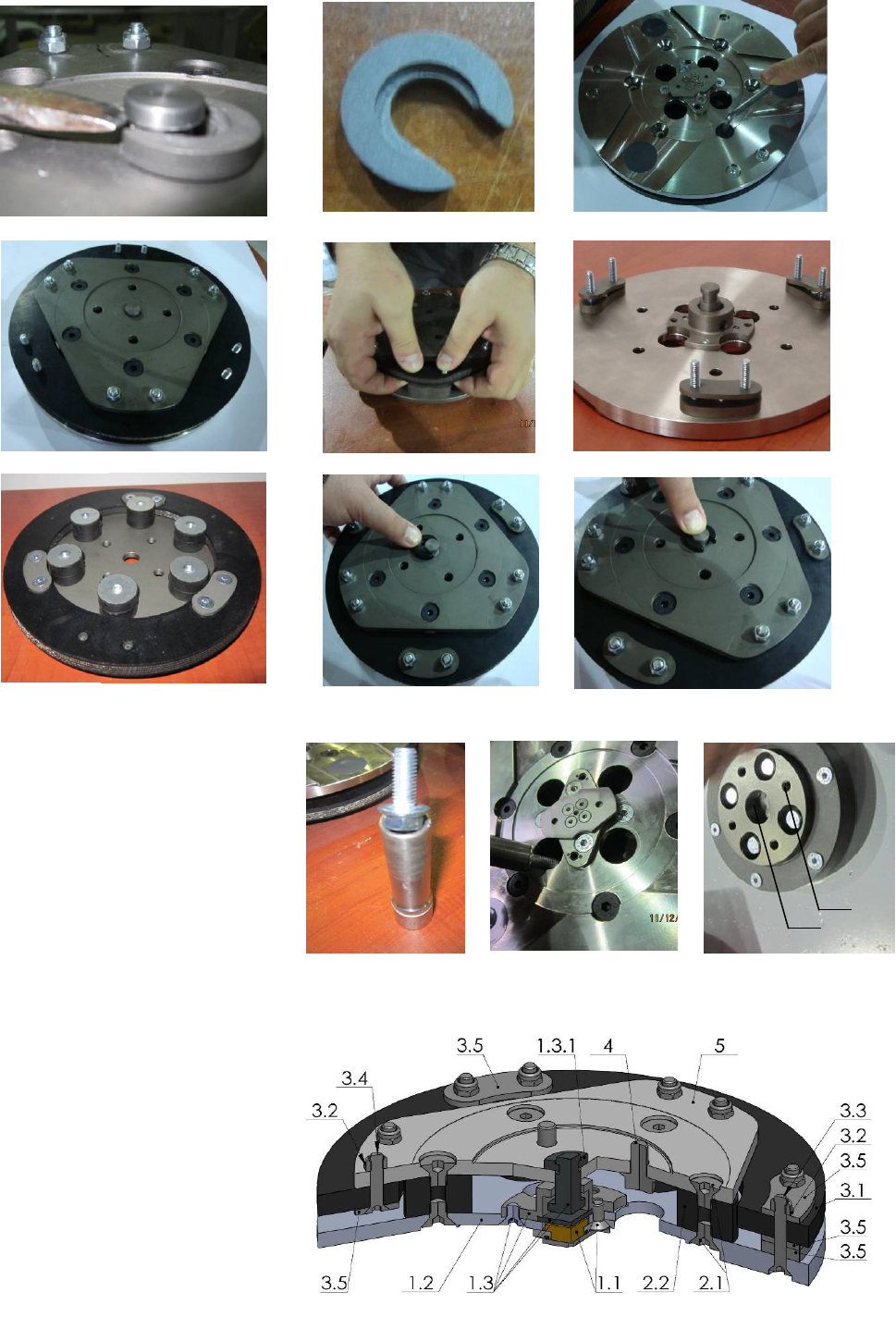
To check or replace the buffers and the elastic elements , the tool holders have to be dismounted.
You will need deep metric socket 13mm with outside diameter not more than 3/4in to unscrew the four bolts (Fig.8.2.1) and remove
the holder (Fig.8.2.2) When the tool holder is dismounted, you can change the sealers (V-Ring and Felt-Ring).
By loosening four Hex cap flange bolts (Fig.8.2.3) the adaptor comes loose. Unscrew the six screws of the cap (Fig.8.2.4) holding the
felt-ring. Take out the Felt-Ring, adaptor and V-Ring.
Mount the V-Ring with the smallest lip of the V to inside (Fig.8.2.5) just push the V-Ring so the top is on the same level as the pulley
top (Fig.8.2.6). Then take the adaptor and push the V-Ring down with the adaptor (Fig.8.2.7). The lowest lip of the V-Ring should only
barely touch its gliding surface; also never push the V-Ring down with fingers. Mount the adaptor and the Felt-Ring on top (Fig.8.2.7).
Close the sealers with the cap (Fig.8.2.8) and screw the bolts. Always use the original bolts.
8.3 DISASSEMBLING AND MOUNTING TOOL HOLDER TO CHANGE BUFFERS AND ELASTIC ELEMENT
When the TOOL HOLDER is disassembled you can change defective parts – elastic element, buffers, etc.
Lift the locking pin (Fig.8.3.1) to dismount the retaining washer (Fig.8.3.2). Take out the screws on the buffers and the nuts of the
elastic element (Fig.8.3.3;Fig.8.3.4). Remove the elastic element from the QC plate (Fig.8.3.5). While the holder is dismounted
(Fig.8.3.6;Fig.8.3.7) clean the parts and replace the defective with new ones. Assemble the holder with new buffers with new screws
and new elastic element. Put the retaining washer (Fig.8.3.8) and push the locking pin (Fig.8.3.9). This will prevent the fall of the
washer when mounting the holder on the machine.
Figure 8.2.1
Figure 8.2.2
Figure 8.2.3
Figure 8.2.4
Figure 8.2.5
Figure 8.2.6
Figure 8.2.7
Figure 8.2.8
21
Superabrasive User Manual Original Language Lavina® 25LM-X / Lavina® 25LM-X-HV 1/2016
Figure 8.3.13
Make sure the four bolts holding the adaptor
(Fig.8.3.12) are reliably tighten. Mount the holder on
the machine using the same socket as mentioned in
8.2 (Fig.8.3.10;Fig.8.3.11). The retaining washer fits
into the central hole C of adaptor and the four bolts
into the thread holes Т (Fig.8.3.12). The holder is
centered on the outside diameter of the adaptor.
Ensure the connection of the holder on the forehead
of the adaptor and then tight evenly the four bolts.
Tightening force of the bolts has to be
22...25N.m(16...18 ft/lbs). Mounting the holder
without retaining washer (Fig.8.3.2) is INADMISSIBLE because the security system preventing the separation of part of the holder
in case of broken buffers and elastic element will not function!
You can change the butterfly of the holder without
dismounting the holder of the machine.
Fig.8.3.13 is 3-D section view of the holder,
showing its parts. The numbering is the same as in
Spare parts.
T
C
Figure 8.3.12
Figure 8.3.10
Figure 8.3.11
Figure 8.3.5
Figure 8.3.1
Figure 8.3.2
Figure 8.3.7
Figure 8.3.3
Figure 8.3.4
Figure 8.3.8
Figure 8.3.9
Figure 8.3.6
22
Superabrasive User Manual Original Language Lavina® 25LM-X / Lavina® 25LM-X-HV 1/2016
8.4 CORRECTING SAG OF THE USED PLANETARY CHAIN
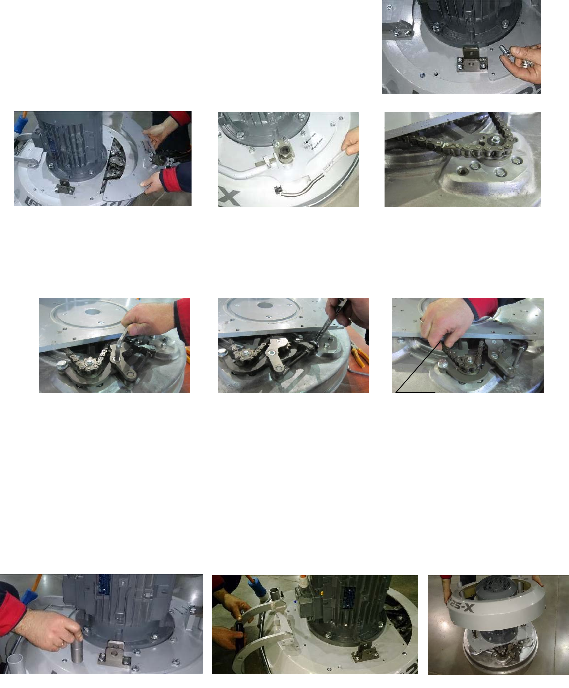
Unscrew the eight bolts (Fig.8.4.1) and take out the cover (Fig.8.4.2) and pull out the
hose of the water sprayer(Fig.8.4.3). Lift the machine in position to change the tools.
Turn manually the holders in order to turn the main head, stop when you see through
the window the chain tensioner (Fig.8.4.4).
Loosen a quarter to 1/2 rev the two bolts of the chain tensioner (Fig.8.4.5) the tensioner should turn with minimum clearence,
without inclination, then unscrew the inner nut. To tension the chain screw the outer nut (Fig.8.4.6). The tensioner of the
planetary chain should allow chain sagging 3...5mm/1/8...3/16 in/ controlled in span X (Fig.8.4.7). When ready screw the two nuts
(Fig.8.4.6) and the screw(Fig.8.4.5).
ATTENTION: NEVER “OVER” TENSION THE CHAIN, THE CHAIN WILL BE DAMAGED
8.5 MOUNTING NEW PLANETARY CHAIN
The planetary chain is replaced with new one when the step/drive of the chain tensioner is finished or there is a break in the
integrity of the chain.
Unscrew the eight bolts (Fig.8.4.1) and take out the cover (Fig.8.4.2) and pull out the hose of the water sprayer (Fig.8.4.3). Lift
the machine in position to change the tools. Turn manually the holders in order to turn the main head, stop when you
see through the window the chain tensioner (Fig.8.4.4). Separate the carriage from main head, pull out motor plug (Fig. 3.1),
water tubes and vacuum tubes (Fig. 3.2) (Fig. 3.3). Take off handle (without water tubes) (Fig. 8.4.3). Release the pin sets (Fig. 3.4)
which attach the head to the carriage. Take off the weight holders(Fig. 8.5.1), machine support(Fig. 8.5.2) and the service window
Figure 8.4.7
X
Figure 8.4.5
Figure 8.4.6
X
Figure 8.4.1
Figure 8.4.2
Figure 8.4.3
Figure 8.4.4
Figure 8.5.1
Figure 8.5.2
Figure 8.5.3
23
Superabrasive User Manual Original Language Lavina® 25LM-X / Lavina® 25LM-X-HV 1/2016
(Fig. 8.4.2) so you can dismount the top cover(Fig. 8.5.3).
Loosen the two nuts(Fig.8.4.6) and uscrew the two screws of the tensioner (Fig.8.4.5)(Fig.8.5.4)(Fig.8.5.5). Take the chain
tensioner(Fig.8.5.6). Pull out the split pin (Fig.8.5.7) and the chain link pin (Fig.8.5.8) (Fig.8.5.9). Take the chain, and put on the
same way the new chain, get in the chain link pin and the split pin (Fig.8.5.9) (Fig.8.5.8) (Fig.8.5.7).
Mount the chain tensioner (Fig.8.4.6). Screw the two screws (Fig.8.5.4)(Fig.8.4.5). Loosen a quarter to 1/2 rev the bolt of the chain
tensioner (Fig.8.4.5) the tensioner should turn with minimum clearence, without inclination, then unscrew the inner nut. To
tension the chain screw the outer nut (Fig.8.4.6) . The tensioner of the planetary chain should allow chain sagging
3...5mm/1/8...3/16 in/ controlled in span X (Fig.8.4.7).
When ready screw the two nuts (Fig.8.4.6) and the screw(Fig.8.4.5).
ATTENTION: NEVER “OVER” TENSION THE CHAIN, THE CHAIN WILL BE DAMAGED
8.6 REPLACING THE PLANETARY DRIVING CHAIN WHEEL AND PLANETARY TENSIONER
Check and repeat the instruction in 8.5 MONTING NEW
PLANETARY CHAIN.
Unscrew bolt pos.1 take the chain pulley pos.3 together with the
sealer pos.5. Change the sealer and mount it to the chain pulley
pos.3. Apply lithium grease on the shaft and mount back the
wheel and the front washer pos.2 as shown on (Fig.8.6.1). Screw
the bolt by using always the “blue” thread locking adhesive.
Tightening force of the bolts has to be 9...11N.m(6.6...8 ft/lbs).
Figure 9.6.1
Figure 9.5.7
Figure 9.5.8
Figure 9.5.9
Figure 9.5.6
Figure 9.5.5
Figure 9.5.4
Figure 8.6.1
24
Superabrasive User Manual Original Language Lavina® 25LM-X / Lavina® 25LM-X-HV 1/2016
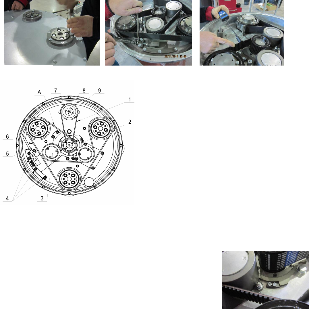
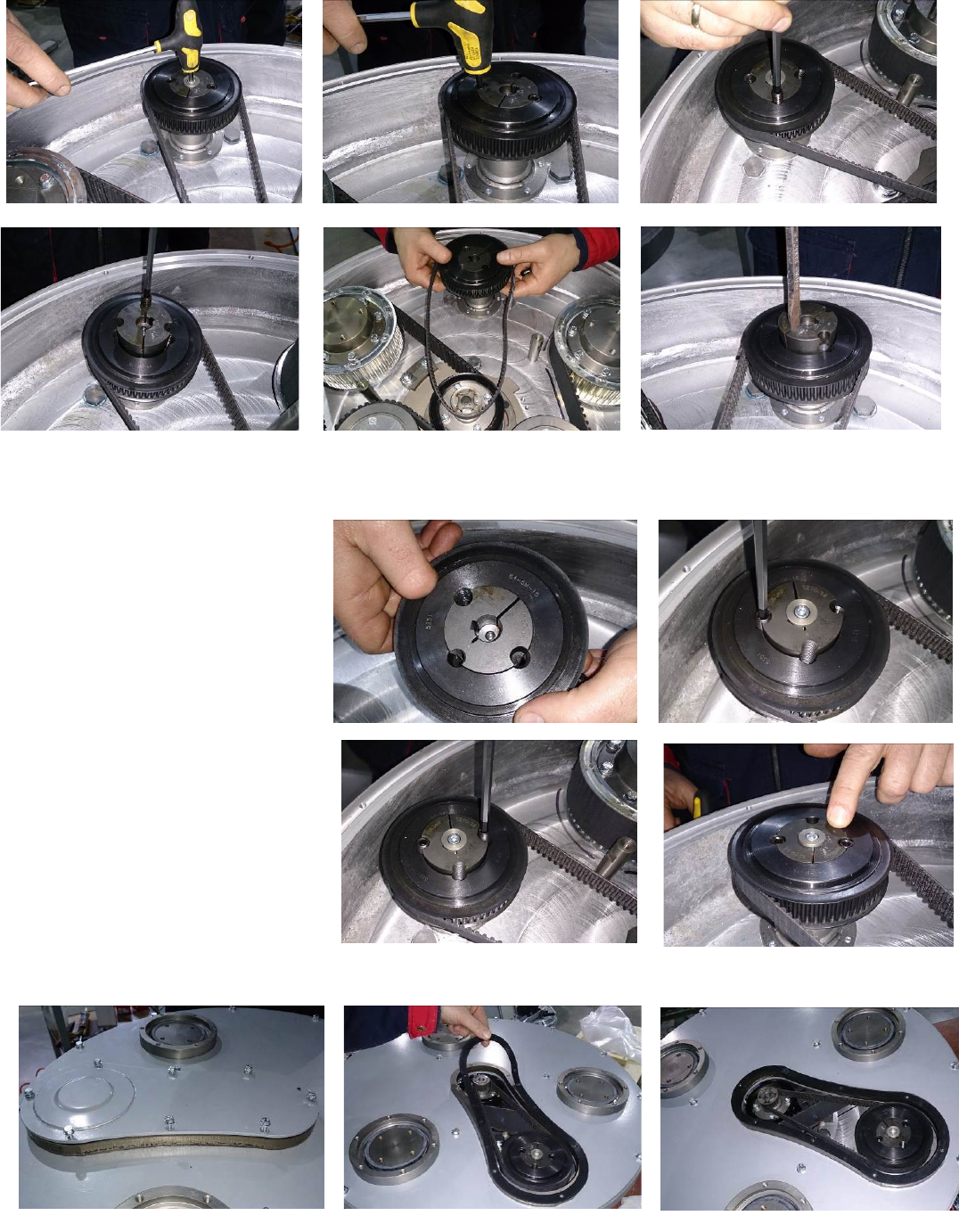
8.7 TENSIONING AND REPLACING THE BELTS
The transmission of the machine has two timing belts (main belt and
planetary belt) of maintenance free type. To change the main belt you
have to remove all holders and dismount their adaptors. Dismount the
sealing. Carefully check the friction surface (flanges of the lower cover
and the outside diameter of the adaptors). Decide if they are in good
condition (wear out, smoothness of surface) and whether they can
work until next inspection. Remove the bottom cover, unscrew the
bolts on the outskirt and the three bolts of the spacers ( Fig. 8.7.1).
Under the cover on the outskirt there is a sealer, and the spacers have
O-Rings. The change of all seals together with the belts is
recommended.
Fig.8.7.5 shows the scheme of belts location. To dismount the old
belts first dismount the planetary belt pos.1 and after that the main
belt pos.6.
To dismount the main belt pos.6 unscrew nuts on pos.4 and pos.5
enough to be able to turn the tensioners pos.3 around the central axle.
Clean the washers and space around, and check if all bearings of pulley
units or tensioners are in good condition (check for too much
clearance or rolling noise). Rotating the tensioner will allow the centre
distance to be reduced in such a way that the timing belt may be fitted without force. Installation with the use of force is NOT
permissible at any time as this can damage the high quality, low stretch tension cord and other components. This damage is often
not visible. Put the belts in pos.6 as per the scheme, and pay attention for their correct position in every pulley. Screw up until it
stops and loosen on the half moons the nuts on pos.4, allowing the rotation of the tensioners at minimum inclination.
Using nuts on pos.5 tighten the belt, verifying again the correct position of the belt, and the correct gearing in every pulley.
Rotate the gear while tensioning to allow regular tension distribution on the belt. Control
the tension using Frequency tension Tester (Optibelt 3 TT) (Fig. 8.7.3). Tension in span “А” of
the belt should be 120-130Hz. It is possible for tensioning while changing the belt to use pre-
installed support (Fig.8.7.5-2) (Fig.8.7.6) (only when its factory position is not changed), to
limit the turn of the tensioner when the required belt tension is done.
ATTENTION:NEVER “OVER” TENSION THE BELT, THE BELT WILL BE DESTROYED AND IT WILL
NEVER RECOVER ITS ORIGINAL TENSION
To dismount the planetary belt (Fig.8.7.5-1) unscrew the screw of the front washer (Fig.8.7.7) and the two screws of the conical
sleeve (Fig.8.7.8). Screw one screw in the free thread(Fig.9.7.9), to push the washer down (Fig.8.7.10); take the conical sleeve and
the belt (Fig.8.7.11). You can help with a flat screw driver if the sleeve is not going out easy. (Fig.8.7.12).
Figure 8.7.3
Figure 8.7.1
Figure 8.7.2
Figure 9.7.4
Figure 8.7.5
Figure 8.7.6
25
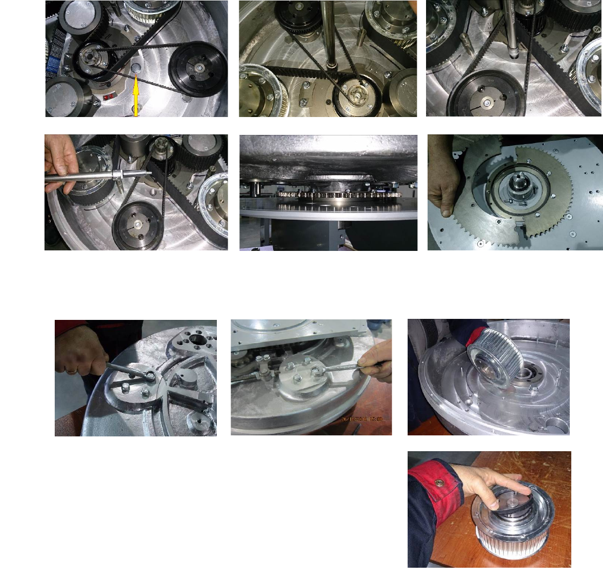
Superabrasive User Manual Original Language Lavina® 25LM-X / Lavina® 25LM-X-HV 1/2016
The essembly is on reverse order, and is important to match the threads of the conical sleeve and the belt washer(Fig.8.7.13). Put
the front washer (Fig.8.7.14), on the screw use always the “blue” thread locking adhesive. Tightening force of the bolts has to be
4,5...6N.m(3,3...4,4 ft/lbs). Put carefully
the two binder screws by leaving the
central thread
free.(Fig.8.7.14)(Fig.8.7.15). Insert the
screws up to revolution and ½ by
alternating until the conical sleeve pull up
the belt pulley. The conical sleeve must
be aligned in height with the belt
washer(Fig.8.7.16).
Dismounting the planetary belt is
possible without removing of the
Bottom cover assembly. Unscrew the
eight bolts, take the service window
cover and the
sealing(Fig.8.7.17)(Fig.8.7.18). Dismount
the planetary belt (see 8.7.)
Figure 8.7.10
Figure 8.7.11
Figure 8.7.12
Figure 8.7.7
Figure 8.7.8
Figure 8.7.9
Figure 8.7.13
Figure 8.7.14
Figure 8.7.16
Figure 8.7.15
Figure 8.7.19
Figure 8.7.18
Figure 8.7.17
26
Superabrasive User Manual Original Language Lavina® 25LM-X / Lavina® 25LM-X-HV 1/2016
8.8 REPLACING THE PLANETARY DRIVEN CHAIN WHEEL
Dismount the planetary chain and the tensioner and see Fig.8.5(MONTING NEW PLANETARY CHAIN).
Dismount the tool holders, sealers and bottom cover see Fig.8.7(TENSIONING AND REPLACING THE BELTS). Unscrew
the cap that gives access to the fastening bolts of the driven chain wheel (Fig.8.8.1)(Fig.8.8.2). Roll the main head to
the position when from the hole of the cap you see a fastening bolt of the driven chain wheel (Fig.8.8.3).
You will need magnetic deep metric socket 10mm with outside diameter not more than 11/16 in to unscrew the six
bolts (Fig.8.8.3)(Fig.8.8.4) (Fig.8.8.5).
Driven Chain Wheel is composed by two symmetrical halfs(Fig.8.8.6). Mount on the reverse order.
8.9 REPLACING THE PULLEY UNITS
Dismount guard, top cover, maintenance window chain tensioner, driven chain wheel, bottom cover and belts as previous
described.
Unscrew the four bolts of each pulley between the base plate and the motor base
disc (Fig.8.9.1)(Fig.8.9.2) and dismount the pulley (Fig.8.9.3).
A seal (Fig.8.9.4) should be placed on top of the pulley before mounting.
Figure 8.8.1
Figure 8.8.2
Figure 8.8.3
Figure 8.8.4
Figure 8.8.5
Figure 8.8.6
Figure 8.9.1
Figure 8.9.2
Figure 8.9.3
Figure 8.9.4
27

Superabrasive User Manual Original Language Lavina® 25LM-X / Lavina® 25LM-X-HV 1/2016
8.10 REPLACING THE PLANETARY UNIT
Unscrew the six bolts (Fig.8.10.1)(Fig.8.10.2) and press down the planetary unit.
When mounting back secure with sealant (fig.8.10.3).
8.11 REPLACING PARTS FROM THE DRIVING OF THE CARRIAGE
Lift the lorry so both wheels are on the air. Unscrew the four bolts (Fig. 8.11-1) and take the bearing of the wheel (Fig.8.11-2).
From this position you can replace the loose key(Fig. 8.11-3) or the
sealing V ring (Fig.8.11-4) without dismounting other parts. If a
replacement of the half clutch is necessary (Fig. 8.10-5) unscrew the
four bolts (Fig. 8.11- 6). During reassembly you have to assure the
coaxiality of the wheel bearing against the hole of the half clutch (Fig.
8.11-5). Tighten the four bolts by hand (Fig. 8.11-1) and roll the bearing,
so there is no increase or reduce of resistance on rolling. (Plug the lorry
into the power supply, put switch SLOPE in pos. ON and tighten the
four bolts (Fig. 8.11-1) tightening torque - 45N.m. (this way the parts of
the electromagnetic clutch will take working position). After release of
the electromagnetic clutches (put switch SLOPE in position OFF and
activatе the button STOP the bearing should scroll easy, without
tangible resistance by hand. To replace the whole driving unit (Fig. 8.11-
7) or engine (Fig. 8.11- 9) unscrew the bolts (Fig. 8.11- 8). During
reassembly you have to assure the coaxiality between the driving unit
and the bearing of the two wheels.
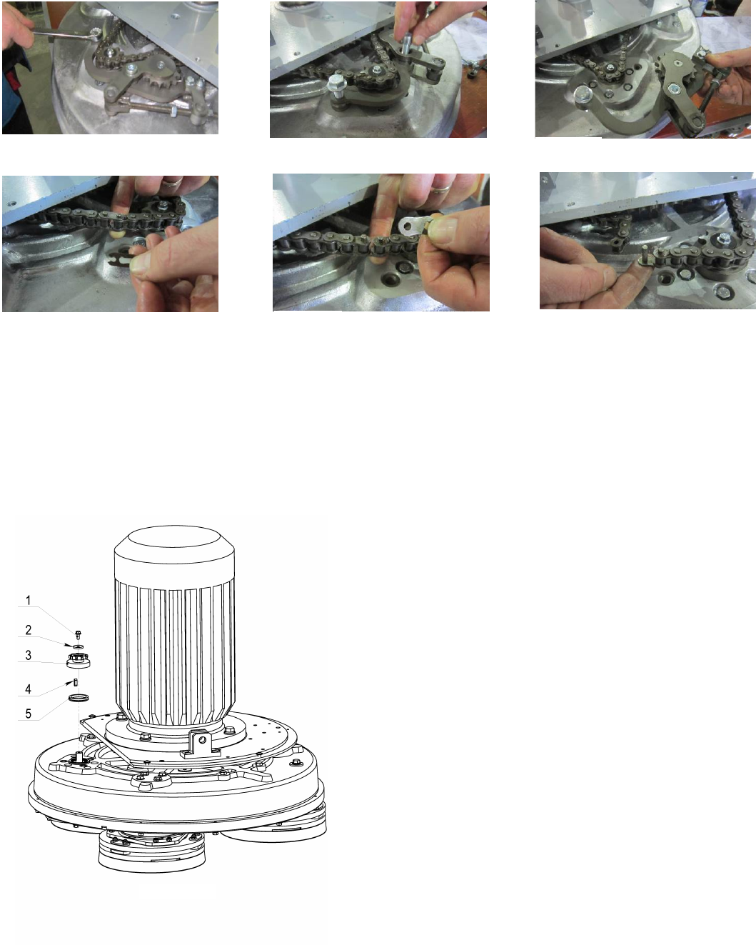
8.12 MOTOR CONNECTION
In case the motor is being replaced, please follow the cable connections in the figures below (Fig.8.12.1 and Fig.8.12.2).
Lavina® 25LM- X
The motor is connected in “Delta”
(Triangle) 230 Volt, reminder for
the wire connection of the motor.
Lavina® 25LM-X-HV
The motor is connected in “Star”
380 Volt, reminder for the wire connection of the motor.
Figure 8.10.3
Figure 8.10.2
Figure 8.10.1
Figure 8.12.1
28
Superabrasive User Manual Original Language Lavina® 25LM-X / Lavina® 25LM-X-HV 1/2016
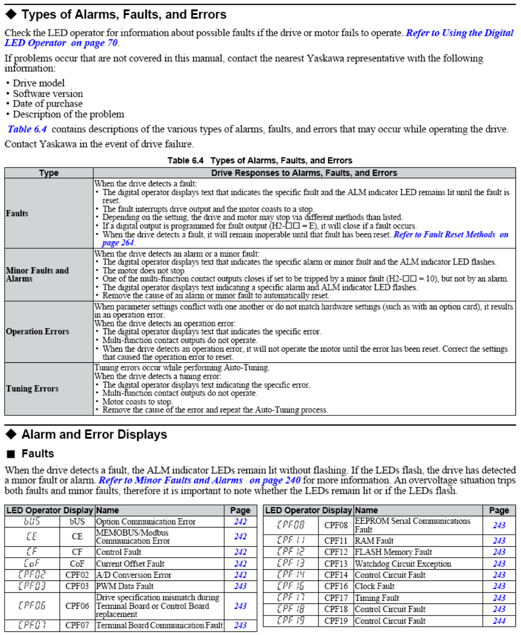
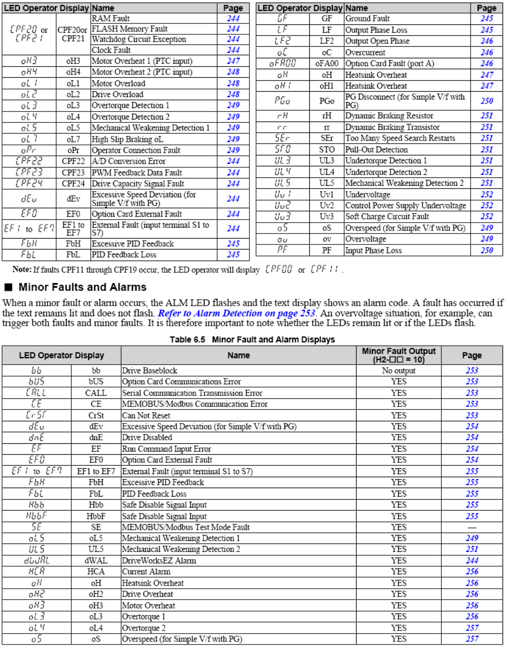
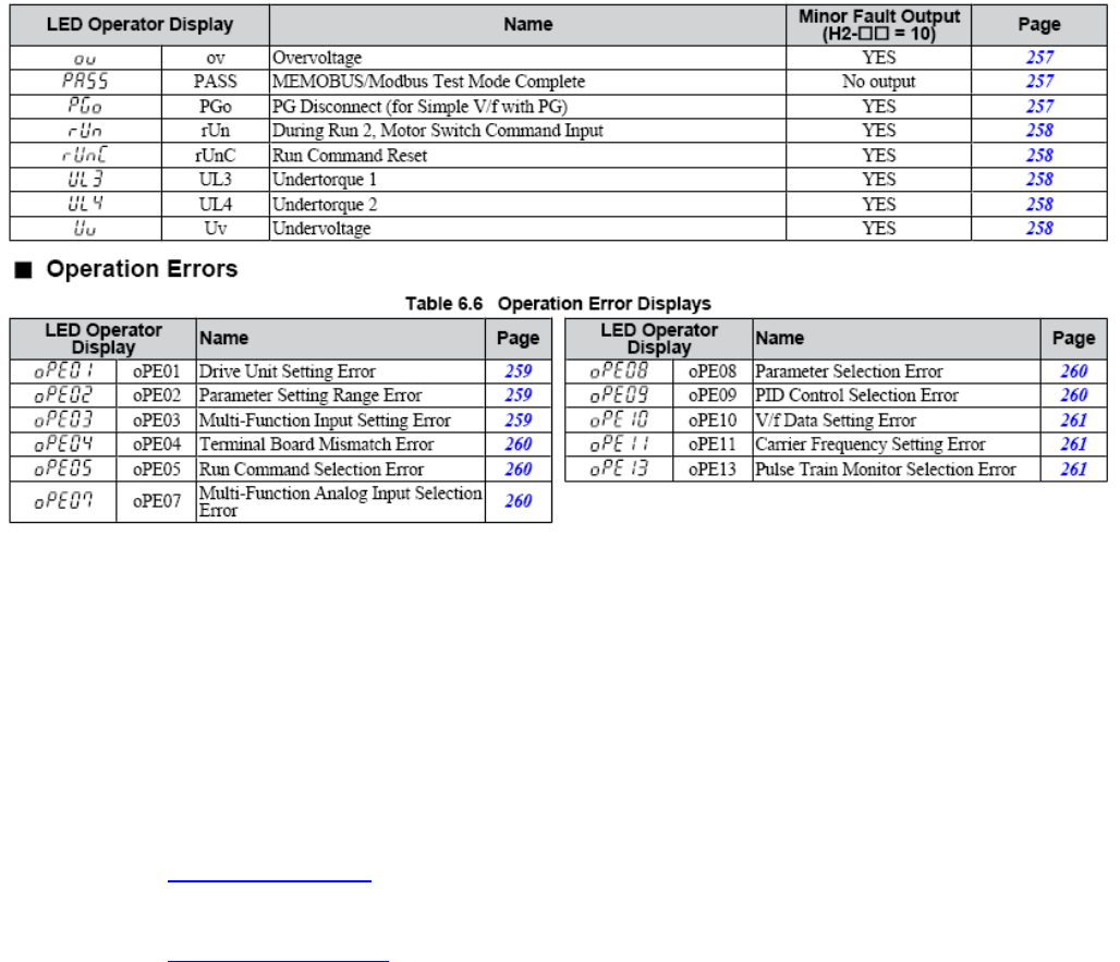
8.13 FAULT DIAGNOSIS INVERTER YASKAWA V1000
Pages are referring to
Yaskawa Electric SIEP C710606 18A YASKAWA AC Drive – V1000 Technical Manual
29
Superabrasive User Manual Original Language Lavina® 25LM-X / Lavina® 25LM-X-HV 1/2016
30
Superabrasive User Manual Original Language Lavina® 25LM-X / Lavina® 25LM-X-HV 1/2016
9. DISPOSAL
If your machine after time is not usable or needs to be replaced, send the machine back to Superabrasive or a local
distribut
or, where a professional disposal complying with the environment laws and directives is guaranteed.
10. MANUFACTURER’S CONTACTS
If you need to contact Superabrasive Inc. with technical support questions, below is the contact
information. Address: 9411 Jackson Trail Road, Hoschton GA 30548, USA
Email: info@superabrasive.us
Tel.: 706 658 1122
Fax: 706 658 0357
Website: www.superabrasive.com
31
Superabrasive User Manual Original Language Lavina® 25LM-X / Lavina® 25LM-X-HV 1/2016
11. SPARE PARTS
ASSEMBLY AND PARTS SPECIFICATIONS
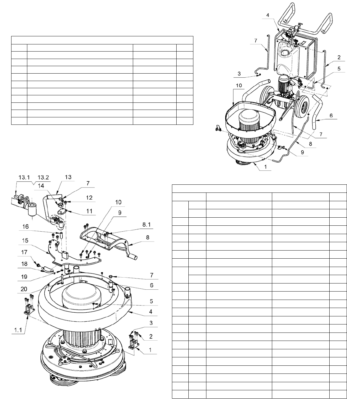
1. LAVINA®25LM-X GENERAL PARTS
No.
Item No.
Description
Pcs.
1
L25LMX-10.00.00
Main Head
1
2
MAR8.71
Tube
1
3
10-16DIN3017
Clamp
2
4 L25LMX-20.00.00 Carriage 1
5 MAR8.25 Tube 1
6
D40L700
Vacuum Hose
2
7
MAR8.85
Tube
2
8
MAR8.110
Tube
1
9
L25SPS-07.03.00.00
Pin Assembly
2
10
L25SPS-05.00.00.00
Guard Assembly
1
2. LAVINA® 25LM-X TOP COVER 1 PARTS
No.
Item No.
Description
Pcs.
1
L25SPS-07.00.00.02-L Left Fork 1
1.1 L25SPS-07.00.00.02-R Right Fork 1
2
M8X16DIN912 Screw 6
3
M8X20DIN7991 Screw 2
4
L25X-19.00.00 Top Cover Assembly 1
5
M6X10ISO7380F Screw 5
6
L25NSPS-07.00.00.05 Back Weight Holder 2
7
L25SPS-07.00.00.29 Rubber Buffer 3
8
L25LMX-18.00.00 Machine Support 1
8.1 M8X16DIN6921 Bolt 4
9
L25X-15.00.02 Washer 1
10
M8X20DIN6921 Bolt 8
11
L25X-15.00.04 Support Top L25-X 1
12
M8X16DIN6921 Bolt 2
13
L25S-15.10.00 Bar Assembly L25-S 1
13.1 L25S-15.10.02 Lever 1
13.2 L25S-15.10.03 Spring L25-S 1
14
L25Х-15.10.01 Nut 1
15
L25LX-15.11.00 Inspection Cover 1
16
L25SPS-07.00.00.26 Stud 1
17
H766-21 Knob bolt 1
18
A29.12.00 Spray Unit 1
19
M10DIN127B Spring Washer 1
20
M10X75DIN931 Bolt 1
32
Superabrasive User Manual Original Language Lavina® 25LM-X / Lavina® 25LM-X-HV 1/2016
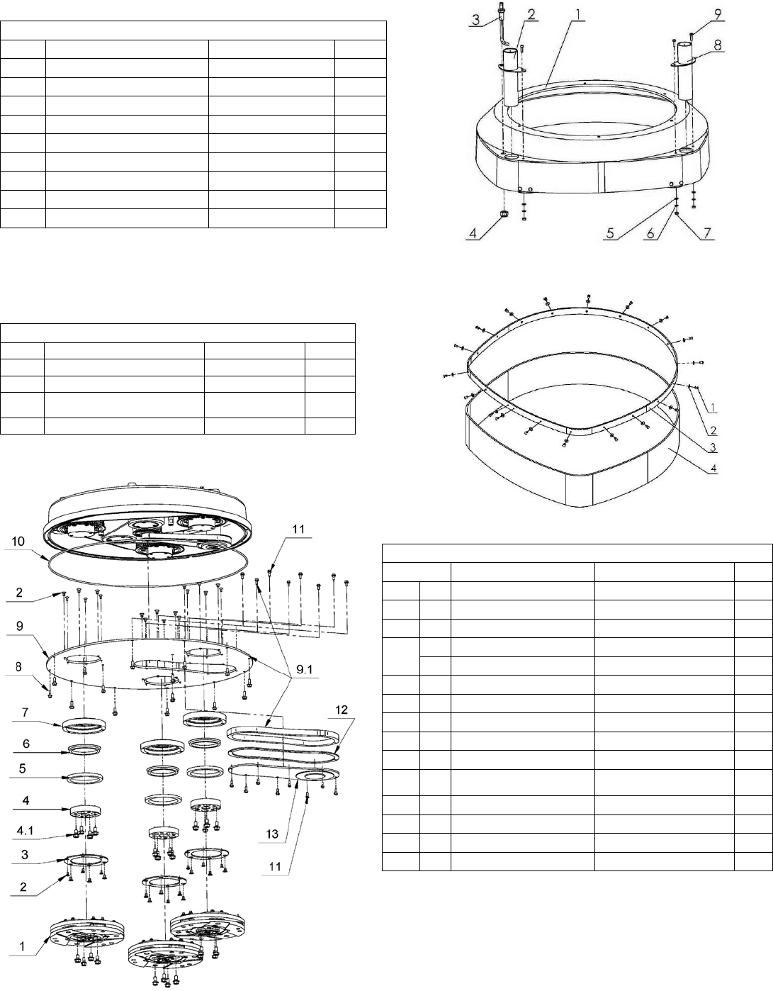
3. LAVINA®25LM-X TOP COVER PARTS 2
No. Item No. Description Pcs.
1 L25X-19.00.01 Top Cover 1
2 L25GS-19.10.00 Vacuum Port 1
3 L25X-19.20.00 Water Fitting 1
4 M12DIN985 Nut 1
5 M5DIN125A Washer 4
6 M5DIN127B Spring Washer 4
7 M5DIN934 Nut 4
8 L25SPS-04.01.00.00 Vacuum Port 1
9 M5X16DIN84A Screw 3
4. LAVINA®25LM-X GUARD PARTS
No.
Item No.
Description
Pcs.
1
D4X10DIN7337 LF12
Rivet
19
2
M4DIN9021A
Washer
19
3 L25SPS-05.00.00.01 Ring 1
4 L25SPS-05.00.00.02 Guard 1
5. LAVINA® 25LM-X BOTTOM COVER 1 PARTS
No.
Item No.
Description
Pcs.
1
A41.00.00 Tool Holder A41 3
2 M6X10DIN7991 Screw 36
3 L25LS-14.00.03 Outer Cover 3
4
A42.03.00 Adaptor 3
4.1 М8х16DIN6921 Bolt 4
5 110X90X8.5 Felt Ring 3
6 TWVA00800 V-Ring Type A 3
7 L25LS-14.00.02 Flange 3
8 М6х16DIN6921 Bolt 15
9 L25X-14.00.00 Bottom Cover Assembly 1
9.1 L25X-14.00.01-K
Bottom Cover with
manhole
1
10 D4X2X1880 Seal 1
11 M5X12DIN6921 Bolt 16
12 L25X-14.00.04 Sealer Inspection Cover 1
13 L25X-14.10.00 Inspection Cover 1
33
Superabrasive User Manual Original Language Lavina® 25LM-X / Lavina® 25LM-X-HV 1/2016
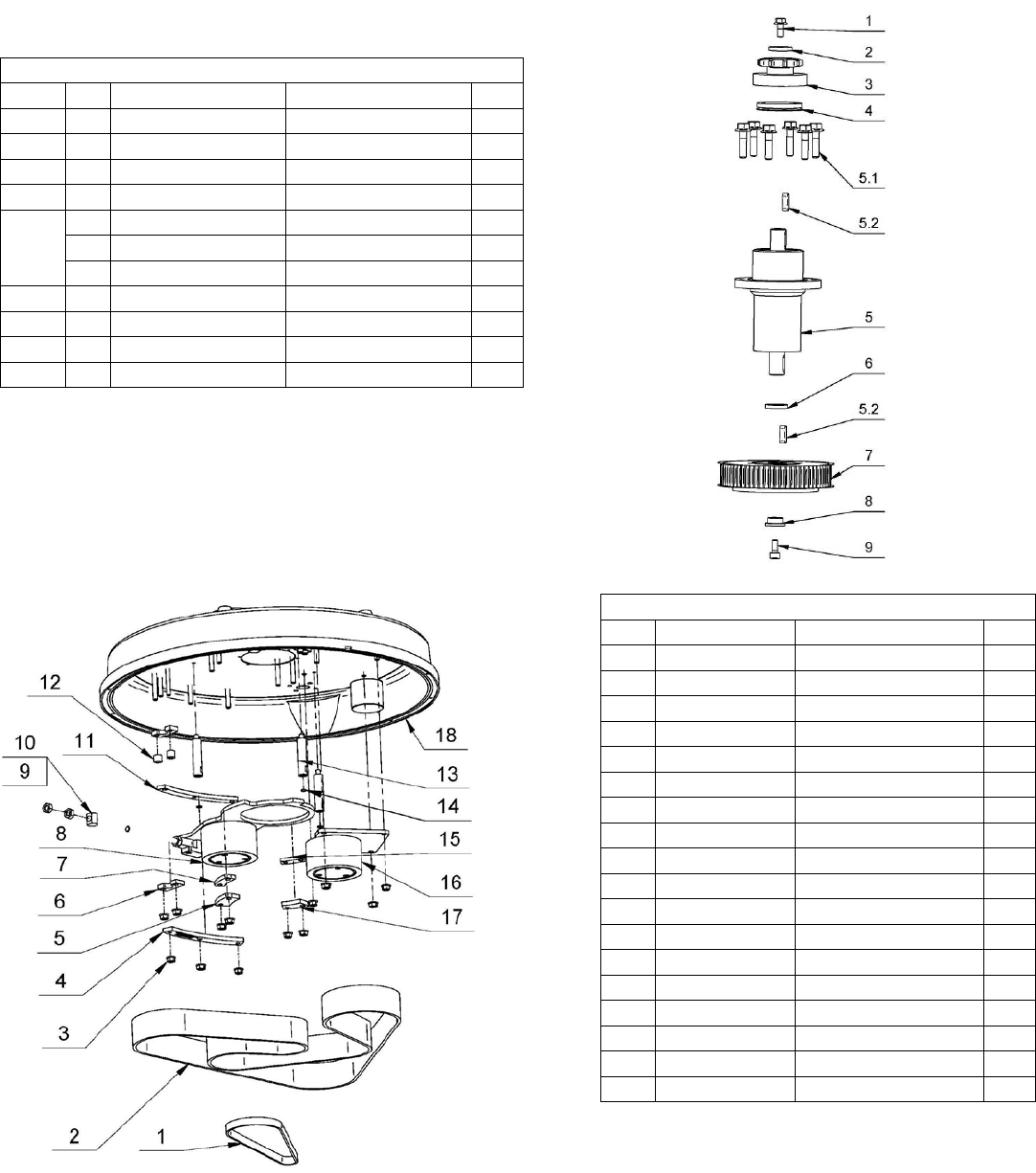
6. LAVINA® 25LM-X PLANETARY DRIVE PARTS
No. Item No. Description Pcs.
1 M6X16DIN912 Screw 4
2 L25X-03.00.00 Pulley 1
3 M16X35DIN7991 Screw 1
4 L25LX-10.00.55 Front Washer 1
5 L25LX.10.10.00 Central Pulley 1
6 B65DIN471 Retaining Ring 1
7 М6х16DIN7991 Screw 6
8 L25X-10.00.17 Cap 1
9 6013 Roller Assembly 2
10 L25SPS-00.00.00.34 Distance Ring 1
11 A10013943 Retaining Ring 1
12
L25X-11.00.00 Pulley Unit Assembly 3
12.1 M8X35DIN6921 Bolt 4
13 TWVA01200 V-Ring Type A 1
14 08B-1-78
Chain
1
15 M6X16DIN6921 Bolt 8
16 L25X-15.00.12
Chain Pulley
2
17 L25X-15.00.03 Flange 1
18 L25LX-15.20.00 Base plate 1
19 M8X16DIN7991 Screw 4
20 M16X35DIN933 Bolt 4
21 M16DIN127B Spring Washer 4
22 M16DIN125A Washer 4
23
S255 Electro Motor 1
23.1 DIN6885A12X8X36 Key 1
24 D4X2X850 Seal 1
25
L25X-17.00.00
Chain Tensioner
1
25.1 M10X35DIN6921 Bolt 1
25.2 M10x35DIN912 Screw 1
34
Superabrasive User Manual Original Language Lavina® 25LM-X / Lavina® 25LM-X-HV 1/2016
6.1. LAVINA® 25LM-X PULLEY UNIT ASSEMBLY
Model No. Item No. Description Pcs.
1 1 M5X12DIN6921 Bolt 1
2 2 L25X-10.00.46 Front Washer 1
3 3 L25X-16.20.00
Chain
Pulley Assembly 1
4 4 TWVA00320 V-Ring Type A 1
5
L25Х-16.00.00 Bearing Body 1
5.1 M6X25DIN6921 Bolt 6
5.2 DIN6885А5X5X16 Key 2
6 6 L25Х-16.00.03 Distance Ring 1
7 7 TB 64_5M-15-1210-14 Pulley Unit Assembly 1
8 8 L25X-10.00.44 Front Washer 1
9 9 M5X12DIN912 Screw 1
7. LAVINA® 25LM-X BOTTOM COVER 2 PARTS
No.
Item No.
Description
Pcs.
1 HP645 5MHP15 Timing Belts 1
2 HL2400 8MHL50 Timing Belts 1
3 M8DIN6923 Nut 13
4 L25L-10.00.14 Sector 1
5 L25L-10.00.12 Sector 1
6 L25L-10.00.07 Support 2
7 L25L-10.00.11 Sector 1
8 L25X-12.00.00 Tensioning Support 1
9 L32C-14.20.04 Nut 1
10 M10DIN934 Nut 2
11 L25L-10.00.13 Sector 1
12 L25L-10.00.08 Washer 2
13 L25X-10.00.13 Distance Bolt 3
14 D6X2 O-Ring 3
15 L25X-10.00.34 Sector 1
16 L25X-13.00.00 Deflection Pulley 1
17 L25X-10.00.35 Sector 1
18 L25X-10.00.01 Disc 1
35
Superabrasive User Manual Original Language Lavina® 25LM-X / Lavina® 25LM-X-HV 1/2016
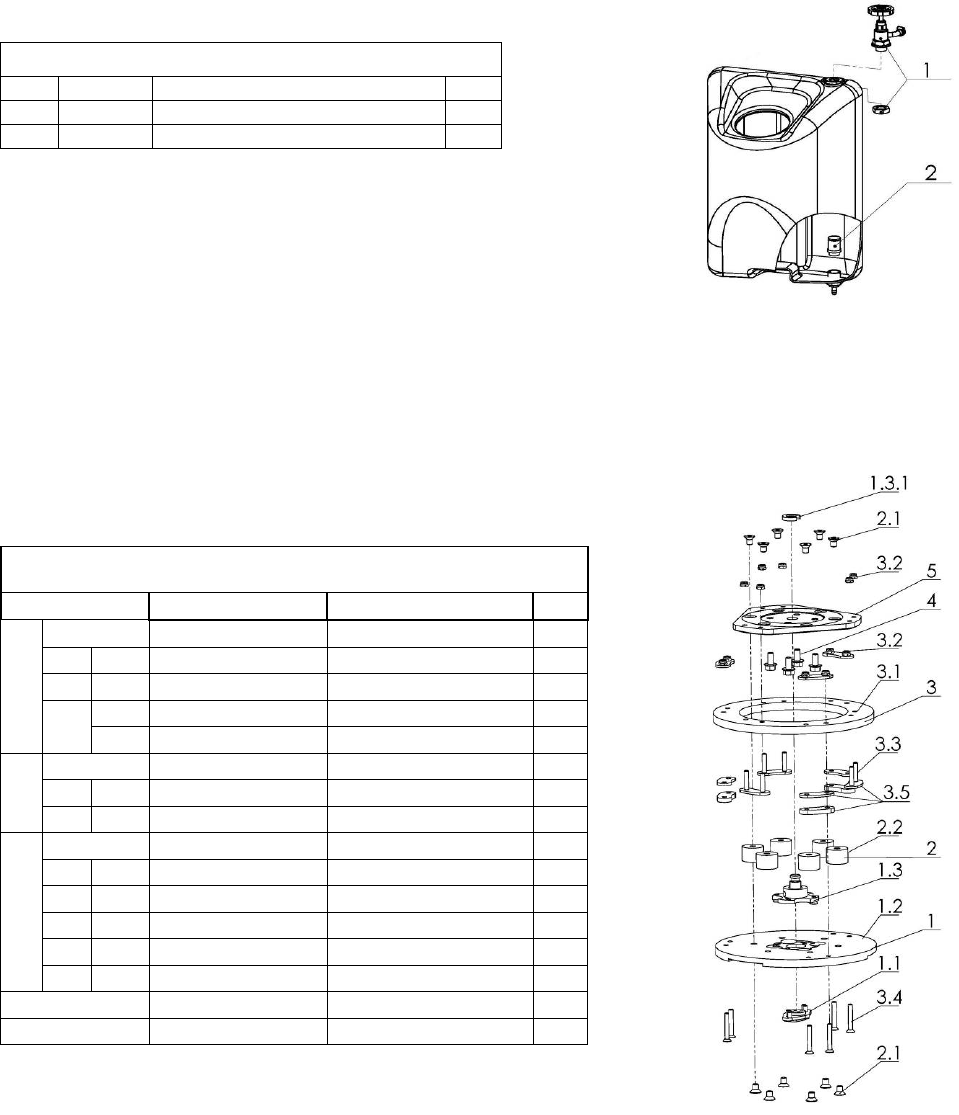
8. LAVINA®25LM-X WATER TANK PARTS
No.
Item No.
Description
Pcs.
1
A29.50.00
Regulator
1
2
1/2"
Filter
1
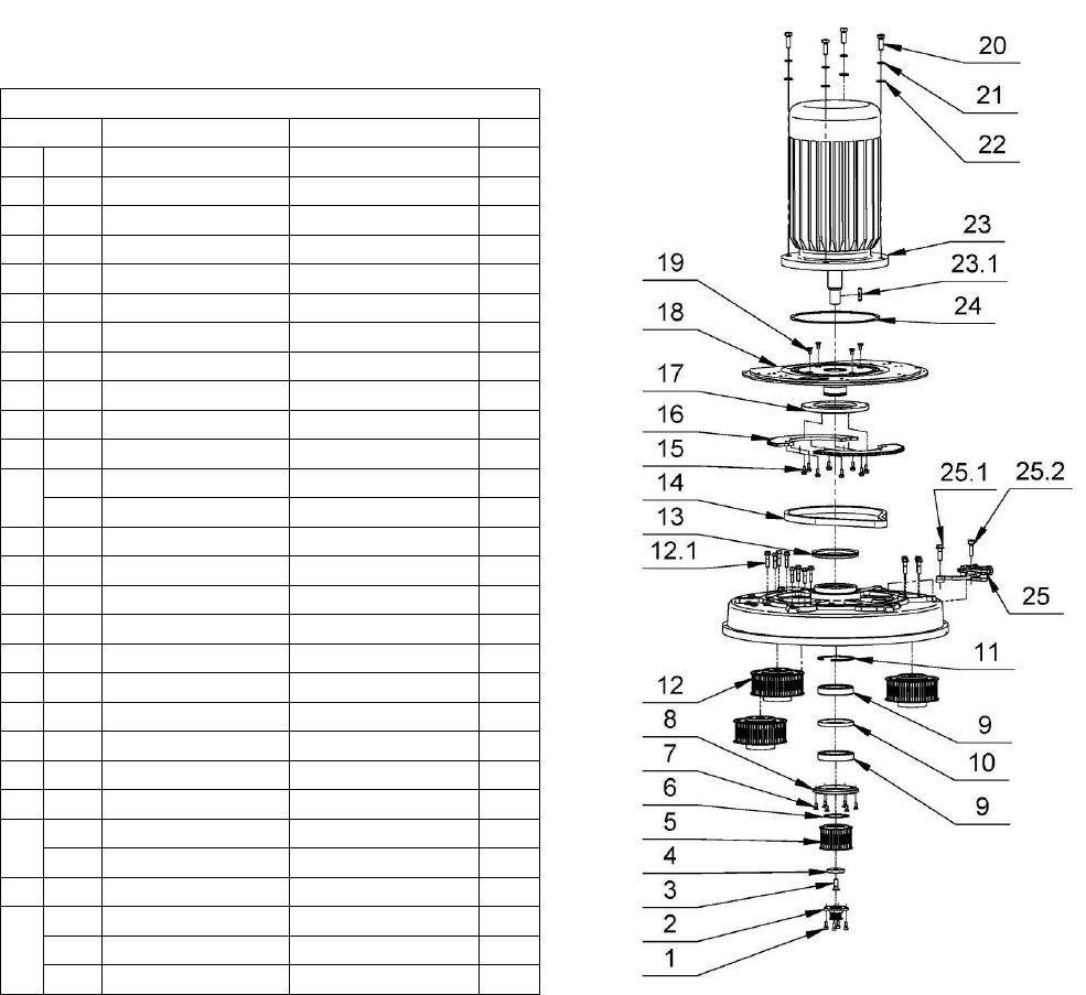
9. LAVINA®25LM-X TOOL HOLDER PARTS/
SEE ALSO FIG.8.7.13/
(POS.1 INCLUDE POS.1.1;1.2;1.3/POS.1.3 INCLUDE POS.1.3.1 and etc.)
No.
Item No. Description Pcs.
1
A41.10.00 Quick Change Assembly 1
1.1
A31.12.00 Keylock Set 1
1.2
A41.11.00 Quick Change plate 1
1.3
. A41.12.00 Security set 1
1.3.1 A41.00.05 Washer A41 1
2
A25.00.10-K Buffer with
two screw 6
2.1
M8X12DIN7991 Screw 12
2.2
A25.00.10 Buffer 6
3
A41.20.03-K Driving Set A41 1
3.1
A41.20.03 Elastic Element 1
3.2
M6DIN985 Self Locking Nut 12
3.3
M6X40DIN7991 Screw 6
3.4
M6X30DIN7991 Screw 6
3.5
A41.21.00 Set of plates 1
4
М8х16DIN6921 Bolt 4
5
A41.20.01 Flange 1
36
Superabrasive User Manual Original Language Lavina® 25LM-X / Lavina® 25LM-X-HV 1/2016
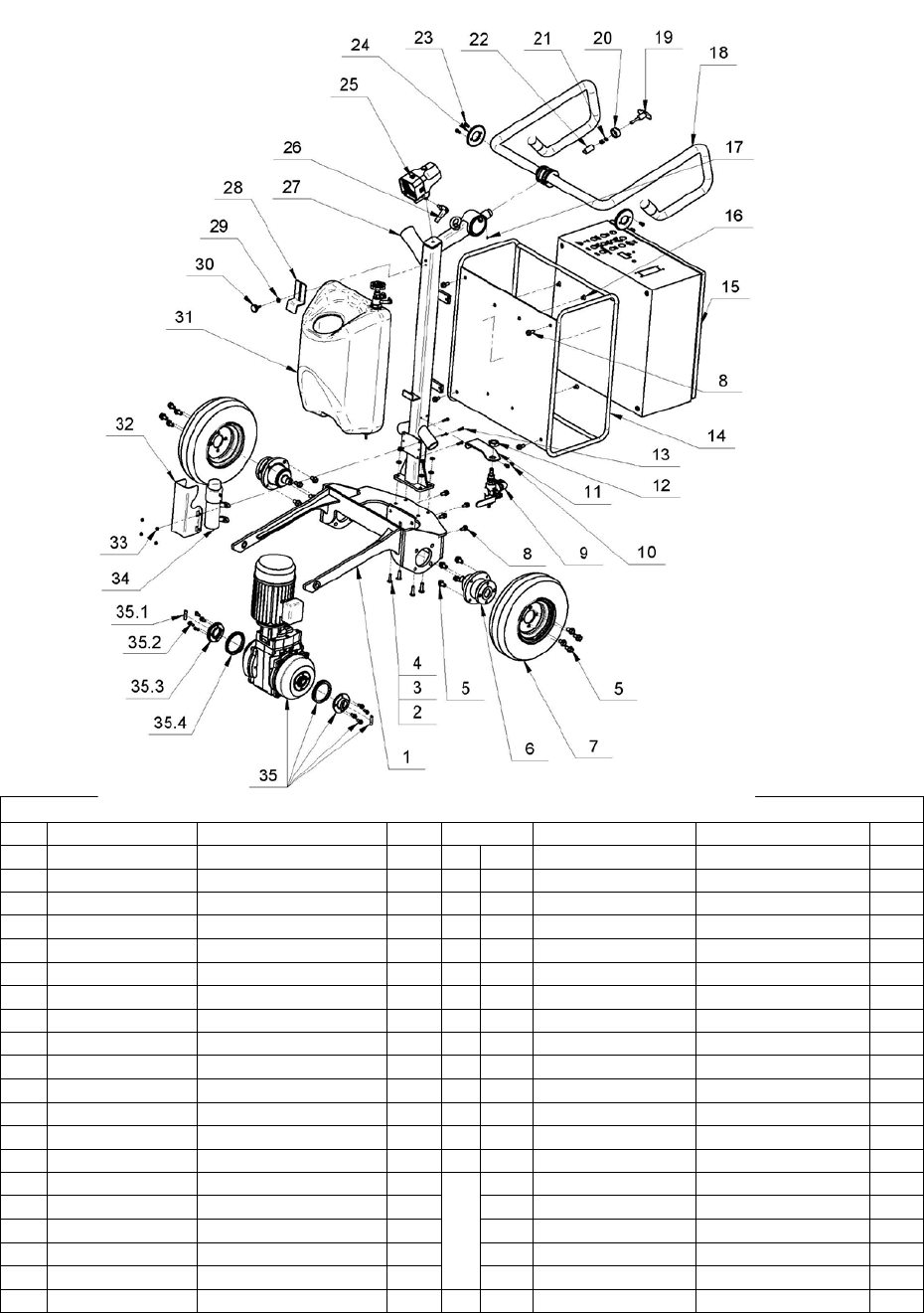
10. LAVINA®25LM-X CARRIAGE PARTS
No.
Item No.
Description
Pcs.
No.
Item No.
Description
Pcs.
1
L25LMX-21.10.00
Frame
1
21
L25S-23.00.07
Spring L25-S
1
2
M8DIN985
Nut
4
22
L25S-23.00.06
Locking bit
1
3
М8DIN125A
Washer
4
23
M6X12DIN912
Screw
4
4
М8X30ISO7380F
Screw
4
24
L25S-23.00.02
End Cover
2
5
M10X20DIN6921
Bolt
8
25
L20NS-30.30.00
Lamp Unit Incl. Cable
1
6
L25LMX-29.00.00
Wheel Bearing
2
26
A58165
Swivel Bolt
1
7
L32R-27.10.00
Wheel assembly
2
27
L25LMX-21.20.00
Column
1
8
M8X20DIN6921
Bolt
8
28
L25P-02.00.00.01
Top Bracket
1
9
A29.40.00
Water Flow Control Unit
1
29
M5UN732
Washer
1
10
M5X12DIN6921
Bolt
2
30
T34391
Knob Bolt
1
11
A29-20.01-01
Flow Unit Base
1
31
A33.10.00
Tank Assembly
1
12 М20X1.5DIN439B Nut 1 32
L25S-20.00.26 Guard 1
13
M5X20DIN933
Bolt
4
33
M5DIN985
Nut
4
14
L25LMX-22.00.00
Guard
1
34
See table 11;pos.10
Water Pump
1
15
L25LMX-28.00.00
Control Box
1
35
L25LMX-27.00.00
Driving Unit
1
16 M8X12DIN7991 Screw 4 35.1 DIN6885A6x6x36 Key 2
17
M6X8DIN915
Screw
1
35.2
М6х16DIN6921
Bolt
8
18
L25S-23.10.00
Handle Assembly
1
35.3
L32MS-27.00.04
Coupling
2
19 L27160 Knob Bolt 1 35.4 TWVA00700 V-Seal 2
20
L25S-23.00.09
Nut
1
37
Superabrasive User Manual Original Language Lavina® 25LM-X / Lavina® 25LM-X-HV 1/2016
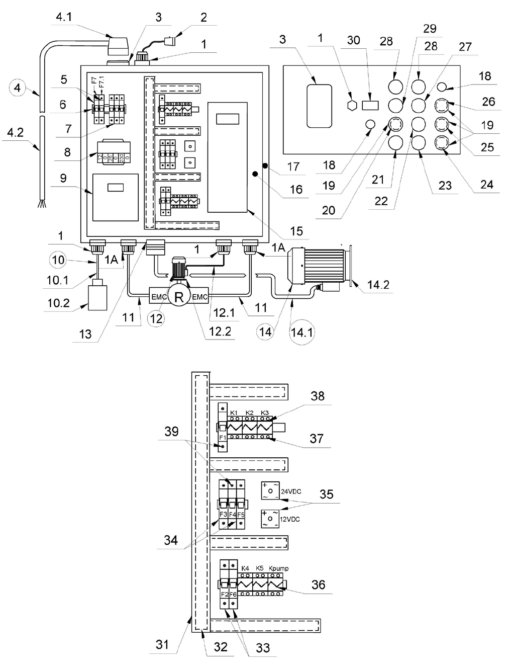
11. LAVINA® 25LM-X CONTROL BOX PARTS 200-240 VOLT
38

Superabrasive User Manual Original Language Lavina® 25LM-X / Lavina® 25LM-X-HV 1/2016
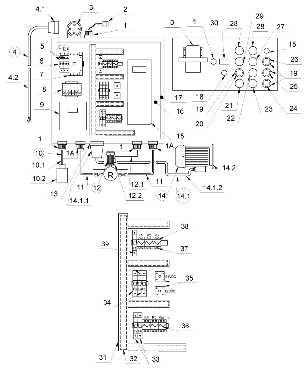
11.LAVINA® 25LM-X CONTROL BOX PARTS 200-240 VOLT
No. Item No. Description Pcs. No. Item No. Description Pcs.
1
L20NS-30.10.01
Cable Gland
3
17
L25LMX -30.10.00
Metal box
1
1A
FXFPAL10M12B
Cable Gland
2
18 L20NS-30.10.04 Potentiometer 2
2 L20NS-30.30.00 Lamp Unit Incl. Cable 1 19 L20NS-30.10.06 Cap 4
3 L25LS-30.30.10 Plug on Control Board 1 20 L25LMXHV-30.10.02 Alarm, Reset button 1
4 L25LS -30.02.00 Cable with Connector and Plug 1 21
L32MXHV-30.10.10
Emergency Stop Button
1
4.1 L25LS -30.02.10 Connector Ass 1 22
L32S-30.10.26
Switch Button SLOPE
1
4.2 L25S -30.02.02 Cable 1 23
L32S-30.10.25
Switch Button ON/OFF Led green
1
5
L32RSHV-30.00.11
Circuit Breaker
2 24
L32MSHV -30.10.02
BACK Button/red/
1
6
L20NS-30.11.02
Rail
1
25
L32MSHV -30.10.01
FOR Button/green/
1
7 L25LS-30.11.03 Circuit Breaker 1 26
L20NS-30.10.07
STOP Button
1
8
L25LMX-30.11.01
Transformer
1
27
L20NS-30.10.13
Water Pump Button
1
9
L25LM-S-30.00.02
Inverter
1
28
L20NS-30.10.12
Button
2
10
L20NS-30.40.00
Water Pump with Cable
1
29 L32S-30.10.26 Forward/Reverse switch 1
11
FXFPAL10B50M
Goffer tube
2
30
L20NS-30.10.15
Revolution counter
1
12
L32RSHV-30.13.00
Electro motor with cable
1
31
L32MSHV-30.11.38
Rail Cover
1
12.1
L32RSHV-30.13.10
Cable 4x1
1
32
L32MSHV-30.11.39
Rail Cable Guide
1
12.2
L32RSHV-30.13.20
Electro Motor
1
33
L32MSHV-30.11.34
Circuit Breaker
2
13 L25LS -30.50.00 Panel socket assembly 1 34
L20NS-30.11.01
Circuit Breaker
2
14 L25LS -30.20.00 Electro Motor Assembly 1 35
L20NS-30.11.08
Rectifier
2
14.1 L25LS -30.20.10 Plug with Cable
assembly 1 36
L20NS-30.11.06
Rail Bracket
6
14.2 S255 Electro Motor 1 37
L20NS-30.11.04
Rail Base
6
15 L25S-30.11.09
Inverter Yaskawa (V1000)
1
38
L32RS-30.11.05
Rail
1
16
L25LMX-30.11.00
Metal box plate
1
39
L32SHV-30.11.01
Circuit Breaker
2
39
Superabrasive User Manual Original Language Lavina® 25LM-X / Lavina® 25LM-X-HV 1/2016
12. LAVINA® 25LMX-HV CONTROL BOX PARTS 440-480 VOLT
40

Superabrasive User Manual Original Language Lavina® 25LM-X / Lavina® 25LM-X-HV 1/2016
12.LAVINA® 25LMX-HV CONTROL BOX PARTS 440-480 VOLT
No. Item No. Description Pcs. No. Item No. Description Pcs.
1
L20NS-30.10.01
Cable Gland
3
16 L25LMXHV-30.11.00
Metal box plate
1
1A
FXFPAL10M12B
Cable Gland
2
17 L25LMXHV -30.10.00
Metal box
1
2 L20NS-30.30.00 Lamp Unit Incl. Cable 1 18 L20NS-30.10.04 Potentiometer 2
3 L25LHVS-30.10.02 Plug on Control Board 1 19 L20NS-30.10.06 Cap 4
4 L25LHVS -30.02.00 Cable with Connector and Plug 1 20 L25LMXHV-30.10.02 Alarm, Reset button 1
4.1 L25LHVS -30.02.01 Connector 1 21
L32MXHV-30.10.10
Emergency Stop Button
1
4.2 L25LHVS -30.02.02 Cable 1 22
L32S-30.10.26
Switch Button SLOPE
1
5
L32RSHV-30.00.11
Circuit Breaker
3 23
L32S-30.10.25
Switch Button ON/OFF Led green
1
6
L20NS-30.11.02
Rail
1
24
L32MSHV -30.10.02
BACK Button/red/
1
7 L20NX-30.11.03 Circuit Closer 1 25
L32MSHV -30.10.01
FOR Button/green/
1
8
L25LMXHV-30.11.01
Transformer
1
26
L20NS-30.10.07
STOP Button
1
9
L25LMSHV-30.00.02
Inverter
1
27
L20NS-30.10.13
Water Pump Button
1
10
L20NS-30.40.00
Water Pump with Cable
1
28
L20NS-30.10.12
Button
2
11
FXFPAL10B50M
Goffer tube
2
29 L32S-30.10.26 Forward/Reverse switch 1
12
L32RSHV-30.13.00
Electro motor with cable
1
30
L20NS-30.10.15
Revolution counter
1
12.1
L32RSHV-30.13.10
Cable 4x1
1
31
L32MSHV-30.11.38
Rail Cover
1
12.2
L32RSHV-30.13.20
Electro Motor
1
32
L32MSHV-30.11.39
Rail Cable Guide
1
13 L25LHVS -30.10.03 Socket 1 33
L32MSHV-30.11.34
Circuit Breaker
2
14 L25LHVS -30.20.00 Electro Motor Assembly 1 34
L20NS-30.11.01
Circuit Breaker
2
14.1 L25LHVS -30.20.10 Plug with Cable 1 35
L20NS-30.11.08
Rectifier
2
14.1.1 L25LHVS -30.02.03 Connector 1 36
L20NS-30.11.06
Rail Bracket
6
14.1.2 L25LHVS -30.20.12 Cable for Electro Motor 1 37
L20NS-30.11.04
Rail Base
6
14.2 S255 Electro Motor 1 38
L32RS-30.11.05
Rail
1
15
L25LHVS-30.11.09
Inverter Yaskawa (V1000)
1
39
L32SHV-30.11.01
Circuit Breaker
2
41
