Guideline Geo WIDERANGE Utility Detection GPR User Manual Introduction som tex s4kmanualen
Mala GeoScience AB (publ) Utility Detection GPR Introduction som tex s4kmanualen
User Manual
Draft
MALA EasyLocator
WideRange
Operating manual
Version 1.0
Draft www.malags.com
2
Draft www.malags.com
3
Table of Contents
_________________________________________________
1 Introduction 4
1.1 Unpacking and Inspection 5
1.2 Repacking and Shipping 5
1.3 Limited Warranty and Liability 5
1.4 Important information regarding the use of this MALA GPR unit 6
2 Hardware and Start Up 7
2.1 Hardware 7
2.2 Start up 7
3 Using the EasyLocator
WideRange 10
3.1 Surveying 13
3.2 The settings menu 14
4 EasyLocator WideRange
specifications 16

Draft www.malags.com
4
1 Introduction
__________________________________________________
Thank you for purchasing the EasyLocator WideRange.
The EasyLocator series of products is the most widely used
GPR-system for utility detection, world-wide. The WideRange
is the latest in a line of easy-to-use tools for the locating
industry. It builds on its predecessors in terms of handling and
user interface while incorporating the latest and most potent
technology currently available.
We at Malå GeoScience welcome comments from you
concerning the use and experience of this equipment, as well
as the contents and usefulness of this manual. Please take the
time to read through the assembling instructions carefully and
address any questions or suggestions to the following:
Main Office: Subsidiary:
Malå GeoScience Malå GeoScience USA, Inc.
Skolgatan 11 465 Deanna Lane
S-930 70 Malå Charleston, SC 29492
Sweden USA
Phone: +46 953 345 50 Phone: +1-843 852 5021
Fax: +46 953 345 67 Fax: +1-843 769 7397
E-mail: sales@malags.se E-mail: sales.usa@malags.se
Technical support issues can be sent to: support@malags.se
Information about MALÅ GeoSciences products is also
available on Internet: http://www.malags.com
Copyright© 2012 Malå Geoscience AB
Draft www.malags.com
5
1.1 Unpacking and Inspection
Great care should be taken when unpacking the equipment.
Be sure to verify the contents shown on the packing list and
inspect the equipment for any loose parts or other damage. All
packing material should be preserved in the event that any
damage occurred during shipping. Any claims for shipping
damage should be filed to the carrier. Any claims for missing
equipment or parts should be filed with Mala GeoScience.
1.2 Repacking and Shipping
If original packing materials are unavailable, the equipment
should be packed with at least 80 mm of shock-absorbing
material. Do not use shredded fibres, paper wood, or wool, as
these materials tend to get compacted during shipment and
permit the instruments to move around inside the package.
1.3 Limited Warranty and Liability
Malå Geoscience warrants that, for a period of 12 months from the delivery
date to the original purchaser, Malå Geoscience products will be free from
defects in materials and workmanship. Except for the foregoing limited
warranty, Malå Geoscience disclaims all warranties, express or
implied, including nay warranty of merchantability or fitness for a
particular purpose. Malå Geoscience will repair and replace parts or
equipment which are returned to Malå Geoscience, transportation and
insurance pre-paid, without alteration or further damage, and which in Malå
Geoscience´s judgement, were defective or became defective during
normal use.
Malå Geoscience assumes no liability for any direct, indirect, special,
incidental or consequential damages or injures caused by proper or
improper operation of its equipment or software, whether or not
defective.
Draft www.malags.com
6
1.4 Important information regarding the use of
this MALA GPR unit
According to the regulations stated in ETSI EN 302 066-1 (European
Telecommunication Standards Institute):
- The CX unit should not be left ON when leaving the system unintended. It
should always be turned OFF when not in use.
- The antennas should point towards the ground, walls etc. during
measurement and not towards the air.
- The antennas should be kept in close proximity to the media under
investigation.
Canadian regulations states that whenever GPR-antennas are in use the
following note apply:
This Ground penetrating Radar device shall be operated only when in
contact with or within 1 m of the ground.
This Ground Penetrating Radar Device shall be used only by law
enforcement agencies, scientific research institutes, commercial mining
companies, construction companies and emergency rescue or firefighting
organizations.
This equipment has been tested and found to comply with part 15 of the
FCC Rules. Malå GeoScience has not approved any changes or
modifications to this device by the user. Any changes or modifications
could void the user’s authority to operate the equipment. See 47 CFR Sec.
15.21.
Draft www.malags.com
7
2 Hardware and Start Up
__________________________________________________
2.1 Hardware
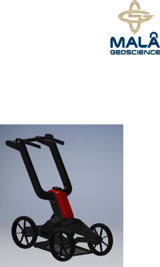
The EasyLocator WideRange is a bandwidth-extended GPR
system designed for use with the EasyLocator ProCart Wide.
The main components are the UWB-transducer(antenna), the
monitor the mechanical carrying system and the batteries. The
system is, preferable powered with one battery and data
communication between the GPR-transducer and the monitor
is managed with an Ethernet link on a cable which carries
power to the monitor as well.
2.2 Start up
Prior to surveying with the system the following easy steps
should be followed.
Make sure that the battery is fully charged. The battery
powers both the transducer and the monitor and is good
for about 5 hour’s operation.
Connect the traducer to the battery by means with cable
supplied, see picture below.
Draft www.malags.com
8
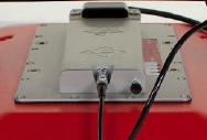
Connect the Monitor to the transducer with the cable
supplied, see picture below.
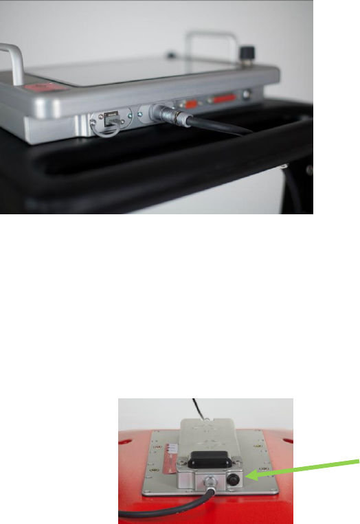
Press and release the button the GPR-transducer,
shortly, do keep it pressed. This will start up the unit;
the LED’s on the panel will start to blink as well as the
LED inside the button, see figure below.
Press the button on the monitor; it’ll take about 30
seconds for the unit to start up.
Draft www.malags.com
9
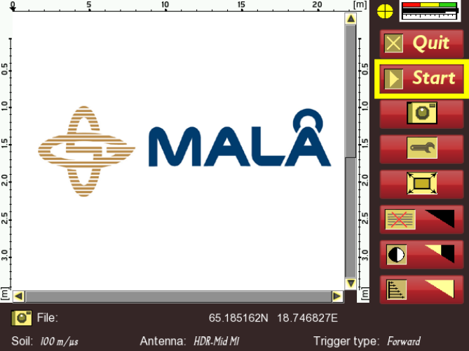
After these simple steps the monitor will display the screen
shown in figure below, and the system is ready for operation.

Draft www.malags.com
10
3 Using the EasyLocator
WideRange
The parts of the EasyLocator WideRange system are shipped
separately. To get started unfold the ProCart, attach the EL
Controller to the controller tray, attach the power/Ethernet
cable, and mount the batteries in the battery bay (behind the
red lid with the MALÅ logo)
Once the unit is un-folded and started as described in previous
paragraph, operation is very straight-forward and self-
explanatory, some details will be described in the following
text.
Referring to the start-up screen is shown in figure below, the
area of the screen between the depth scales are reserved for
data presentation, the lower portion for information about the
ongoing survey and the right column are mainly for controlling
the instrument trough the turn-push button.
Draft www.malags.com
11
Starting from the top-right:
The yellow circle with a cross-hair is indicating the GPS-status;
red means that there’s no GPS attached or no satellites
available, yellow means normal GPS accuracy (about 10m)
and green means that the unit has been able to apply
differential correction.
The scale with red, yellow and green indicates the battery
status. It is divided into two black bars, since there’s an option
of using a separate battery for the transducer. In other
respects, this scale is self-explanatory.
The Quit button is also self-explanatory, press on this and
you’ll have the option for turning off the unit. Note that the unit
should always be turned off this way, since just pulling the
power cable may harm the internal memory of the unit.
Pressing the “Start” button will immediately put the unit into
data collection mode and a radar image of the subsurface will
start to display as soon as the unit is moved.
The camera button enables the operator to save a jpeg image
of the current screen for later downloading to a USB device.
This is intended for documentation purposes.
The wrench button gives possibility to change some of the
settings controlling the data collection process and house-
keeping functionality in the unit, see separate section of this
manual.
The last 3 buttons controls filter to be applied on the data, prior
to display, they are, top to down, background removal, contrast
level and gain function. Pressing the push-turn button while
turning it increases or decreases the strength of these filters,
right-turn; increase and left-turn; decrease.
Draft www.malags.com
12
The bottom part of the screen shows some information about
the ongoing survey. It’s self-explanatory except for the trigger-
type field. The trigger type field explains what controls the data
acquisition, there’s three different types of control; forward
wheel, backward wheel and time triggering. Time triggering
means that the unit collects data with certain frequency,
normally 10 to 20 Hz; it is to be used when surface conditions
prohibit the use of a wheel.
Draft www.malags.com
13
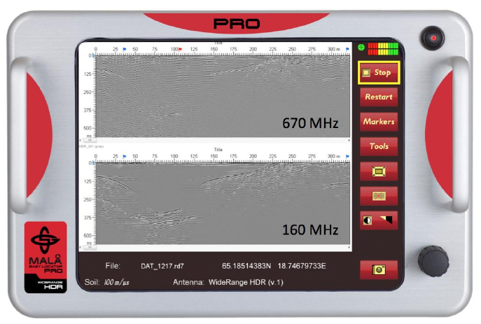
3.1 Surveying
When a survey has been initiated the main menu changes,
see figure below. Now the user may stop the survey, save a
jpeg-image of the current screen check the velocity trough
hyperbola fitting or save a GPS-marker on the current location.
The radargram screen is split in two – the upper part shows
the high frequency part of the data, the lower the low
frequency part.
An important feature in the instrument is the track-cursor
pointed to by the red-arrow in the figure. This cursor will move
with the system, so that if the unit is moved backwards, this
cursor along with a vertical line will start to move back on the
screen. This is the primary function used when locating buried
targets. When the unit is pushed forward again, data collection
will start when you reach the point where you started to move
backward, not before.
Draft www.malags.com
14
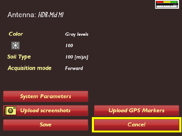
3.2 The settings menu
The settings menu is entered through the wrench button on the
main menu; it is shown in figure below.
Activating the green text-fields, but turning the push-turn
button, and then depressing it gives the user means for
changing the settings. Below the different options are
described.
- Color, the user can switch between gray-scale and color
scale for the displayed radar data. The vast majority of
users prefer the grey-scale, since there’s no natural
interpretation of color for this type of data. It can actually
be quite confusing.
- The sun-symbol is for setting of the backlight of the
screen, default is 100%. By lowering this parameter,
battery-life can be extended by up to 1 hour.

Draft www.malags.com
15
- Soil Type, is defining which ground velocity should be
used when converting reflections from a specific time to
a depth to be shown on the scales. Note that this type
of instrument actually measures time of flight for
electromagnetic waves, in ground. The depth displayed
on the scales is estimations only. Variations in normal
ground are between 80 to 120 meters/microseconds. A
user must be aware of this fact.
The System Parameters sub-menu is not accessible for
operators; it is used for factory calibrations, service centers
during manufacturing and service/repair
The other sub-menus are self-explanatory. Contact your local
dealer if further information is needed.
Draft www.malags.com
16
4 EasyLocator WideRange specifications
__________________________________________________
Useful Bandwidth 80-960 MHz
Time window > 250 ns
Total weight incl. batteries 27 kg
Power supply 12 V Li-ion rechargeable batteries
Operating time 4 hours with standard batteries
Operating temperature -20 to + 50 0C
Data acquisition Wheel or time based
Environmental IP67
Certifications: ETSI, FCC (pending), ICC (pending)
---------------------------------------------------------------------------------
This device complies with Part 15 of the FCC Rules.
Operation is subject to the following two conditions:
1. This device may not cause harmful interference, and
2. This device must accept any interference received,
including interference that may cause undesired
operation.
Changes or modifications not expressly approved by the
party responsible for compliance could void the user’s
Draft www.malags.com
17
authority to operate the equipment.
This equipment has been tested and found to comply with
the limits for a Class B digital device, pursuant to Part
15 of the FCC Rules. These limits are designed to provide
reasonable protection against harmful interference in a
residential installation. This equipment generates uses and
can radiate radio frequency energy and, if not installed
and used in accordance with the instructions, may cause
harmful interference to radio communications. Howev
-
er, there is no guarantee that interference will not occur in a
particular installation. If this equipment does cause
harmful interference to radio or television reception, which
can be determined by turning the equipment off and on,
the user is encouraged to try to correct the interference by
one of the following measures:
•
Reorient or relocate the receiving antenna.
•
Increase the separation between the equipment and
receiver.
•
Connect the equipment into an outlet on a circuit different
from that to which the receiver is connected.
•
Consult the dealer or an experienced radio/TV technician for
help.
---------------------------------------------------------------------------------------------------
This Device complies with Industry Canada License-exempt
RSS standard(s). Operation is subject to the following two
conditions: 1) this device may not cause interference, and 2)
this device must accept any interference, including
interference that may cause undesired operation of the
device.
Draft www.malags.com
18
Under Industry Canada regulations, this radio transmitter
may only operate using an antenna of a type and maximum
(or lesser) gain approved for the transmitter by Industry
Canada. To reduce potential radio interference to
other users, the antenna type and its gain should be so
chosen that the equivalent isotropically radiated power
(e.i.r.p.) is not more than that necessary for successful
communication.