HAN Networks AP24X HAN Access Point User Manual
HAN Networks Co., Ltd. HAN Access Point
UserManual.wiki
>
HAN Networks
>
AP24X User Manual
>
User Manual
Contents
1.
User Manual
2.
User Manual (Statements)
3.
User Manual(Statement)
4.
User Manual (statements)
5.
User Manual (statement)
User Manual
Navigation menu
Upload a User Manual
Namespaces
Wiki Guide
HTML
PDF
Info
Views
User Manual
Discussion / Help
Navigation
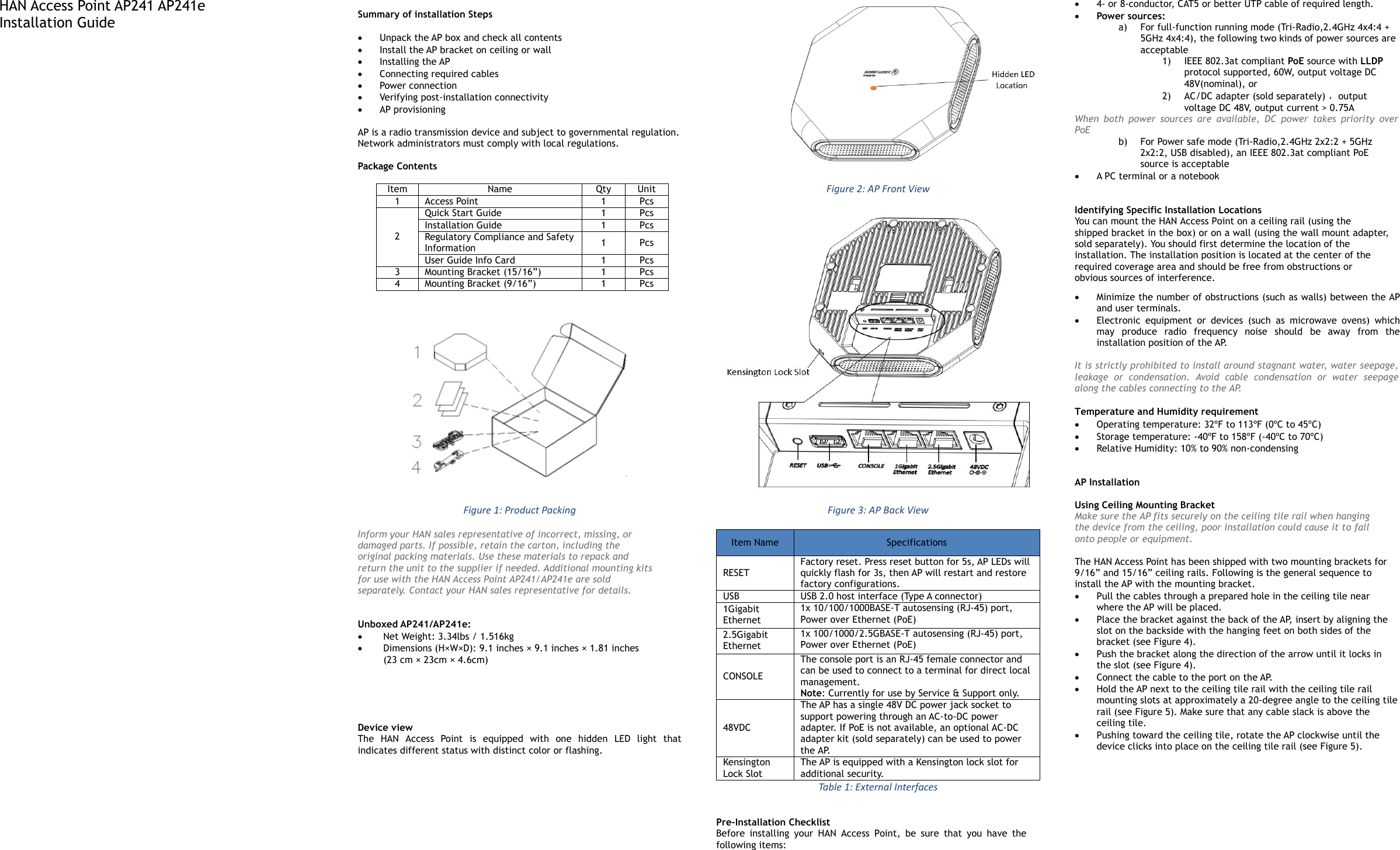
![Figure 4: Attaching the Ceiling Mounting Bracket Figure 5: Mounting the AP Connect Ethernet Use the Ethernet port to connect the AP with a twisted pair Ethernet LAN segment. Use a 4- or 8-conductor, Category 5 UTP cable. The port is an RJ-45 female connector with the pinouts shown in Table2. Ethernet Port /RJ45 Female Pin Signal Name Function 1 BI_DA+ Bi-directional pair +A, PoE Negative 2 BI_DA- Bi-directional pair -A, PoE Negative 3 BI_DB+ Bi-directional pair +B, PoE Positive 4 BI_DC+ Bi-directional pair +C, PoE Positive 5 BI_DC- Bi-directional pair -C, PoE Positive 6 BI_DB- Bi-directional pair -B, PoE Positive 7 BI_DD+ Bi-directional pair +D, PoE Negative 8 BI_DD- Bi-directional pair -D, PoE Negative Table 2: Ethernet Port Pinout Connect Power Sources Confirm that the Ethernet cable is loaded either with 48V DC (nominal) 60W/802.3at compliant PoE source (with LLDP protocol) for full-function running mode, or just with 802.3at compliant PoE source for power safe mode. If not, connect by using the HAN 48V AC-DC adapter kit (sold separately) to the DC Power Socket and AC power jack. If both PoE and DC power are available, the use of DC is preferred. HAN Access Point supports the power adapter provided by HAN ONLY. Verifying Post-Installation Connectivity The LED on the AP can be used at this point to verify that the AP is receiving power and initializing successfully (see Table 3). Red Blue Green Time Line Status ON Power on ON Bootloader-OS loading System start up Flash System running Network abnormal (Interface down) Flash System running Network normal, without SSID created ON System running Network normal, single band working, either 2.4GHz or 5Ghz ON System running Network normal, dual bands working, 2.4Ghz and 5Ghz are both working Flash Flash System running Red and Blue LEDs alternate flashing in specific frequency; OS upgrading Flash Flash Flash System running 3 LEDs alternate flashing in specific frequency; Used for locating an AP Table 3 HAN Access Point LED Meaning Console Port The serial console port allows you to connect the AP to a serial terminal or a laptop for direct local management. This port is an RJ-45 female connector with the pinouts described in Table 4. Note: Currently for use by Service & Support only. Connector Pin Signal Name Function 3 TXD 4 GND 5 GND 6 RXD Pins not listed are not connected Table 4: Console Port Pinout Configuring the HAN Access Point Refer to the Quick Start Guide and Configuration Guide for complete details. Unboxed AP241e (external antenna) Net Weight: 3.48lbs / 1.58kg Dimensions (H×W×D): 9.1 inches × 9.1 inches × 1.81 inches (23 cm x 23cm × 4.6cm) Device view Figure 6 It is installed in the same way as AP241 for the AP installation. In Figure 7, it is shown the way to install the external antennas. Figure 7 Figure 8: With external antennas The external antennas are sold separately. [REMAINING SECTIONS INTENTIONALLY LEFT BLANK]](https://usermanual.wiki/HAN-Networks/AP24X.User-Manual/User-Guide-3737688-Page-2.png)