HANWAY TECHNOLOGY V50L VENTILATION FAN User Manual
HANWAY TECHNOLOGY CO., LTD. VENTILATION FAN Users Manual
USERS MANUAL
Installation instructions
Beforeoperating thisunit, pleasereadand savethese instructions carefully.
The HoneywellTrademark isused underlicense fromHoneywell IntellectualProperties Inc.by Lonon
Industry Company, Ltd.
Honeywell InternationalInc. Makesno representations orwarranties withrespect tothis product.
Page1
Honeywel
l
Decorative Ventilation Fan/Light/Nightligh
t
CLEANING &MAINTENANCE...........................................................................10
SERVICE PARTS..............................................................................................11
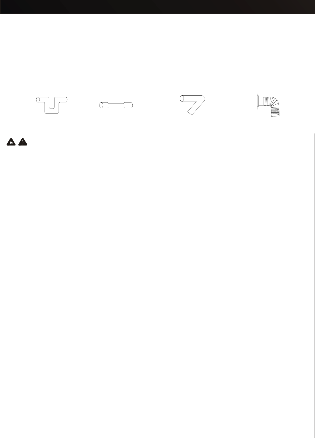
ACCESSORIES................................................................................................2
DESCRIPTION................... .............................................................................3
DIMENSION............................................... .....................................................3
SPECIFICATIONS.............................................................................................4
GENERAL SAFETYINFORMATION....................................................................4
INSTALLATION................................................................................................6
WARRANTY....................................................................................................13
Table of Contents
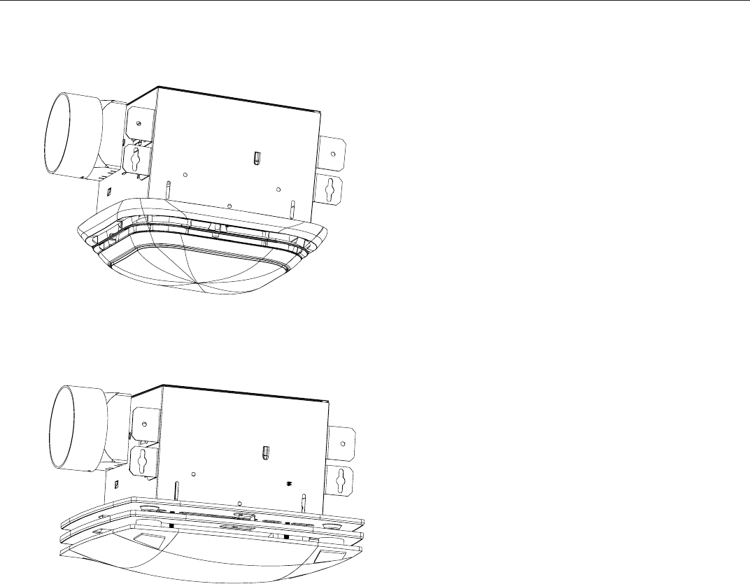
Ventilation Fan/Light/Nightlight
Model V50L/V70L/V80L/V90L
/V100L/V110L Model
ModelDV50L/DV70L/DV80L
/DV90L/DV100L/DV110L
Part name
Picture
Part name
Picture
Quantity Quantity
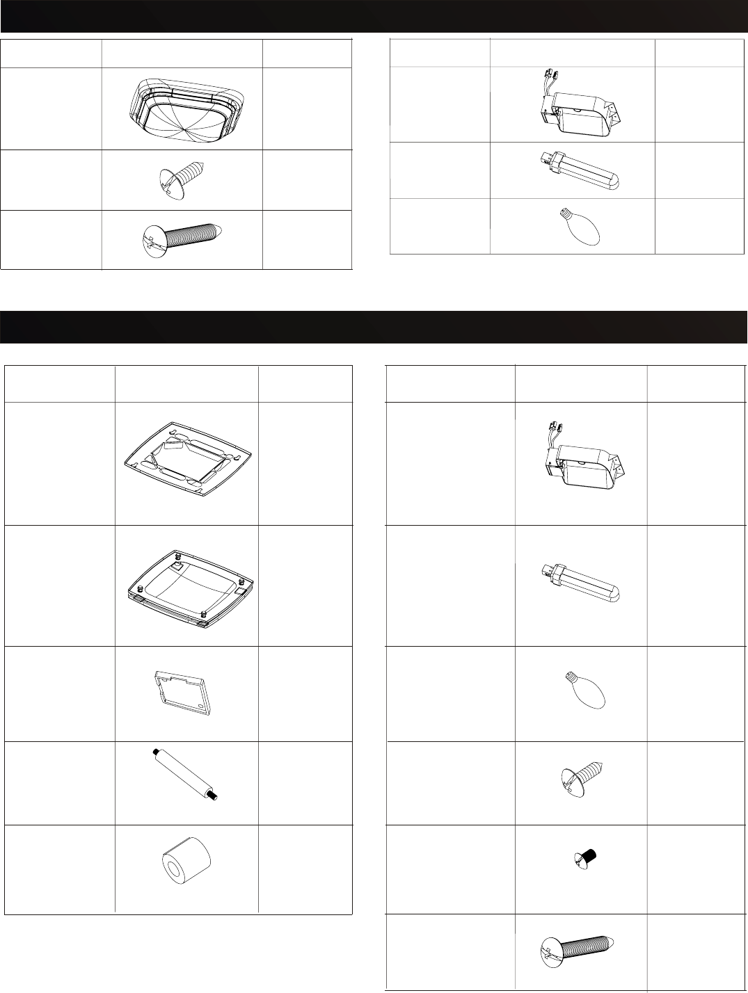
Grille pan 1
1
ScrewA
M4X10
Light unit
26W
Fluorescent
Lamp
2
4
1
4
4ScrewB
M4X12
ScrewC
M4X30 4
4
1
Glass panel
unit
Decorative
cap
Nut
Bolt
ACCESSORIES(DV50L/DV70L/DV80L/DV90L/DV100L/DV110L)
4W
Incandescent
Lamp
1
Part name
Picture
Part name
Picture
Quantity Quantity
Grille
ScrewB
M4X30
1
1
ScrewA
M4X10
Light unit
26W
Fluorescent
Lamp
2
4
1
A
ACCESSORIES(V50L/V70L/V80L/90L/V100L/V110L)
4W
Incandescent
Lamp
1
Page2
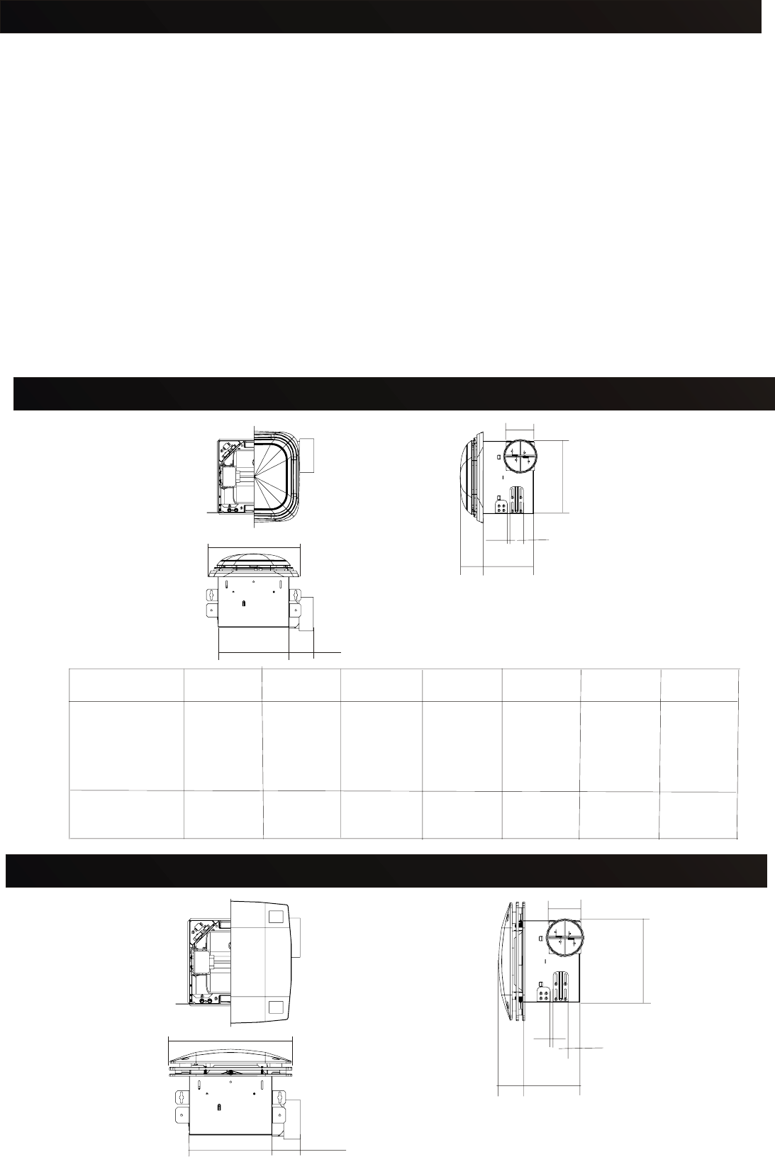
DIMENSION(DV50L/DV70L/DV80L/DV90L/DV100L/DV110L)
B2 7/8
AxA
4
HD
FE
C
Honeywell Ventilation Fanswere designedwith yourcomfort inmind. Withmany different
features, Honeywellfans fityour needswhether yourbathroom isbig orsmall, needsa light,
no lightor evena nightlight,Honeywell fanshave thefeatures youneed.
Honeywell Ventilation Fansare someof thequietest fansever tested.Steamy mirrors,
damp wallsand foggywindows canbe annoyingduring dailylife butwhat's more,this
excess moisturecan leadto thedevelopment ofproblems likemold andmildew,ruined
nsulation andwood rot.Honeywell fanscan helpprovide aventilation solutionto anyroom
n yourhouse. What'smore, Honeywellfans canhelp clearthe airquickly andhelp remove
irritants beforethey causeproblems inyour home.
Honeywell ceilingmounted ventilationfans usehigh-capacity siroccofan drivenby
capacitor motor. Thesirocco fanreduce thenoise level.
The motoris designedto havean extendedservice lifewith reducedenergyconsumption.
Honeywell ventilationfans alsoincorporate athermal cutoff forsafety.The grilleunit can
be quicklydetached fromthe mainunit forcleaning. Adamper forpreventing airbackdraft
is incorporatedinto everyfan.
The lightunit isan energy efficientlighting devicewhich usesone 26Wfluorescent lamp.
DESCRIPTION
B2 7/8
AxA
4
HD
FE
C
DIMENSION(V50L/V70L/V80L/V90L/V100L/V110L)
Model No. ABCDE
V50L
V70L
V80L
V90L
V100L
V110L
10 5/8 8 1/4 8 1/4 61 3/16 5/16
11 3/8 9 1/2 9 1/2 6 3/4 1 5/8 1/2 2 3/8
FH
1/2
2
Page3
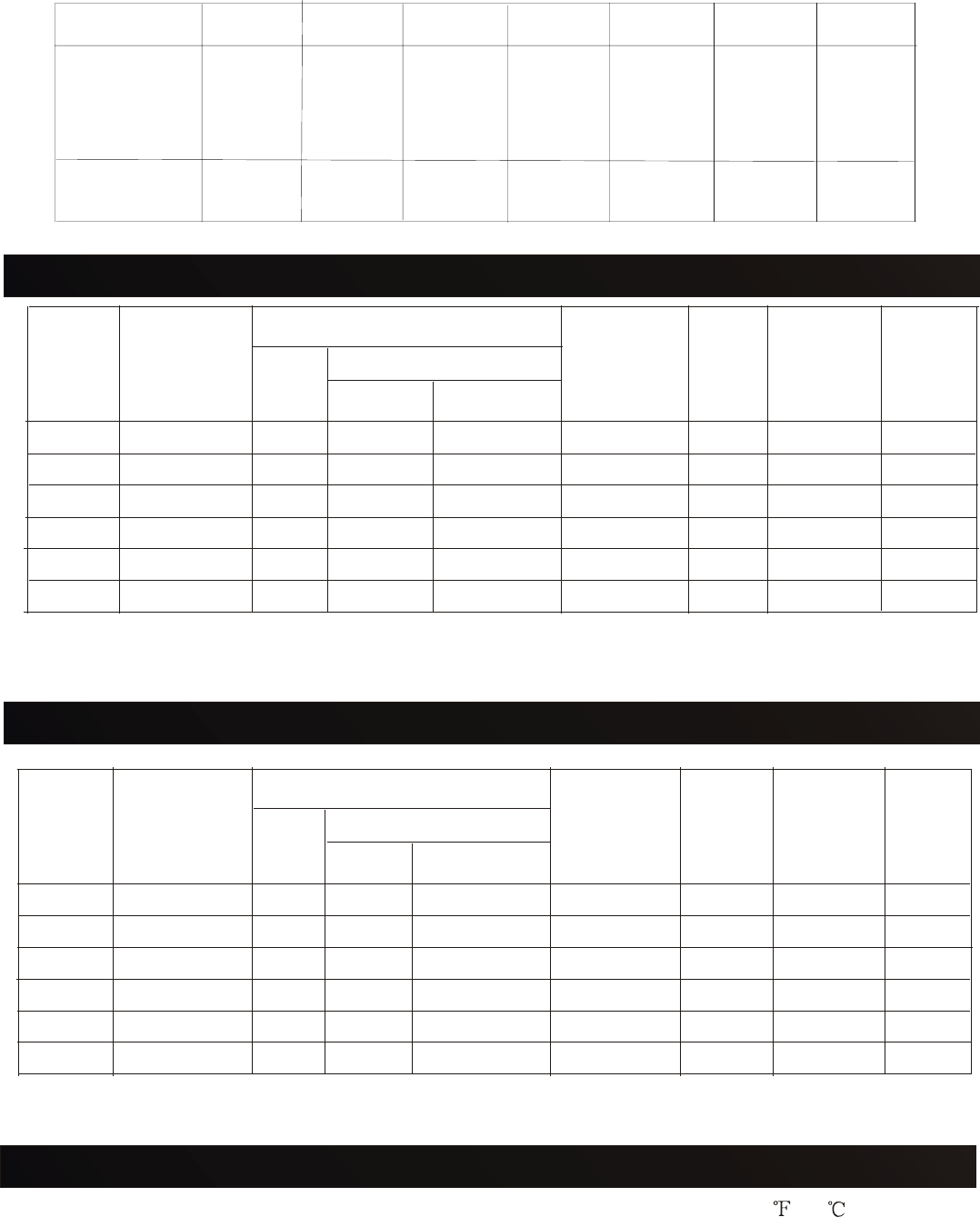
Fan
Unit Light Unit
Light Night Light
*At 0.0"Static pressure.(Pa)
Specifications arebased onHVI standard.
Model
No. Power
Supply
Power consumption*(W) Air
Movement
0.1" WG
(CFM)
Noise
(sone) Duct
Diameter
(inch)
Weight
(lb.)
DV50L 120V/60Hz 18.5 26.0 4.0 50 0.8 4
DV70L 120V/60Hz 22.0 26.0 4.0 70 2.0 4
DV80L 120V/60Hz 26.5 26.0 4.0 80 3.5 4
DV90L 120V/60Hz 48.5 26.0 4.0 90 3.0 4
DV100L 120V/60Hz 37.0 26.0 4.0 100 3.0 4
DV110L 120V/60Hz 40.5 26.0 4.0 110 3.5 4
Page4
A
SPECIFICATIONS(DV50L/DV70L/DV80L/DV90L/DV100L/DV110L)
Model No. ABCDE
DV50L
DV70L
DV80L
DV90L
DV100L
DV110L
12 3/16 8 1/4 8 1/4 61 3/16 5/16 2 9/32
13 9 1/2 9 1/2 6 3/4 1 5/8 1/2 2 3/8
FH
1.Do notinstall thisventilating fanwhere airtemperature mayexceed 104 (40 ).
2.Make surethat theelectric servicesupply voltageis 120V, 60Hz.
3.Follow alllocal electricaland safetycodes, aswell asthe NationalElectrical Code(NEC)
and theOccupation Safetyand HealthAct (OSHA).
4.Always disconnectthe powersource before workingon ornear thefan, motoror junction
box orlight fixture.
5.Protect thepower cordfrom sharpedges, oil, grease, hotsurfaces, chemicalsor other
objects.
GENERAL SAFETYINFORMATION
Fan
Unit Light Unit
Light Night Light
Model
No. Power
Supply
Power consumption*(W) Air
Movement
0.1" WG
(CFM)
Noise
(sone)
Duct
Diameter
(inch)
Weight
(lb.)
V50L 120V/60Hz
17.5
26.0 4.0 50 0.8 4
V70L 120V/60Hz 20.0 26.0 4.0 70 2.0 4
V80L 120V/60Hz 26.5 26.0 4.0 80 3.0 4
V90L 120V/60Hz 47.0 26.0 4.0 90 3.5 4
V100L 120V/60Hz 37.0 26.0 4.0 100 3.0 4
V110L 120V/60Hz 40.0 26.0 4.0 110 3.5 4
A
SPECIFICATIONS(V50L/V70L/V80L/V90L/V100L/V110L)
*At 0.0"Static pressure.(Pa)
Specifications arebased onHVI standard.
Page5
Fig.1
6.Do notkink thepower cord.
7.This unitis approvedfor useover abathtub orshower wheninstalled ina GFCIprotected
branch circuit.
8.This unitmust begrounded.
9.This unitis U.L.Listed. Type I.C.Inherently protected.
10.These modelsare ULlisted fortub andshower enclosures.
11.Provide suctionparts withproper ventilation.
12.Do notinstall theunit whereducts areconfigured asshown inFig.1.
GENERAL SAFETY INFORMATION
TO REDUCETHE RISKOF FIRE,ELECTRIC SHOCK,ORINJURY TO PERSONS,OBSERVE
THE FOLLOWING:
1.Use thisunit onlyin themanner intendedby themanufacturer. Ifyou havequestions,
please contactthe manufacturerat theaddress ortelephone numberlisted inthe
warranty.
2.Before servicingor cleaningunit, switchthe poweroff atservice panel and lockthe
service disconnectingmeans toprevent powerfrom beingswitched onaccidentally.
When theservice disconnectingmeans cannotbe locked,securely fastena prominent
warning device,such as a tag,to theservice panel.
3.Installation workand electricalwiring mustbe doneby aqualified person(s)in accordance
with allapplicablecodes andstandards, includingfire-rated constructioncodes and
standards.
WARNING:
4.Sufficient airis neededfor propercombustion andexhausting ofgases throughthe flue
(chimney) offuel burningequipment toprevent backdrafting.Follow theheating
equipment manufacturer'sguideline andsafety standards,such asthose publishedby
the NationalFire Protection Association(NFPA)and theAmerican Societyfor Heating,
Refrigeration andAir ConditioningEngineers (ASHRAE),and thelocal codeauthorities.
5.When cuttingor drillinginto wallor ceiling,make surenot todamage electricalwiring and
other hiddenutilities.
6.Ducted fansmust alwaysbe ventedto theoutdoors.
7.NEVER placea switchwhere itcan bereached from atub orshower.
8.Solid statecontrols maycause harmonicdistortion thatcan causemotor hummingnoise.
9.To reducethe riskof fireor electricshock, Donot usethis fanwith anysolid-state speed
control device.
10.Not tobe ina ceilingthermally insulatedto avalue greaterthan R40.
11. Fluorescentmodels only:Do notuse adimmer switchto controlthe lightof thisunit.
12. Motorand grilleassembly mustbe installedwith housingassembly thatare marked(on
their cartons)to indicatethe suitabilitywith thismodel. Otherhousing assemblycannot
be substituted.
13. To reducethe riskof fireuse onlythese 26watt fluorescentlamps and4watt maximum
type Cincandescent lampnightlight.
GENERAL ELECTRIC:F26DBXT4/SPX27/4P
PANASONIC:FDS26E27/4
LONON: YDW2U26C/120,YDW2U26D/120
Page6
GENERAL SAFETY INFORMATION
GENERAL SAFETYINFORMATION
Fig.2
CAUTION:
1.For general ventilating use only. Do not use to exhaust hazardous or explosive
materialsand vapors.
2.This productis designedfor ceilinginstallation only. Thisproduct isdesigned for
installation inceilings upto a12/12 pitch.Ductwork mustpoint up.DO NOTMOUNT THIS
PRODUCT ONA WALL.
3.The lightfixture assemblymust bemounted tothe fanhousing assemblyincluded with
this product.Do notmount thelight fixtureassembly toa wiringoutlet box.
4.To avoidmotor bearingdamage andnoisy and/or unbalancedimpellers, keepdrywall
spray,construction dust,etc. offpower unit.
5.Please readspecification labelon productfor furtherinformation andrequirements.
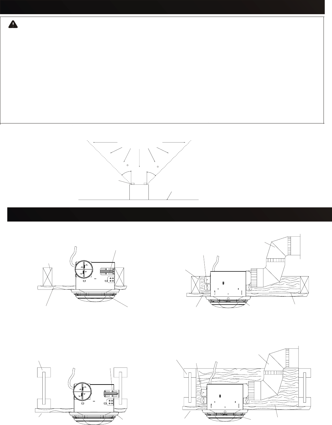
6. Notfor usein cookingarea. (Fig.2)
(Cooking area)
Do notinstall aboveor
Inside thisarea
Floor
Cooking
Equipment 45
45
Power cable
Ceiling joist
GrilleCeiling material
Suspension
bracket
Housing
Housing mounteddirectly tojoist
2x4(or larger)
Discharge parallelto joist
Suspension
bracket
Power cable
Additional framing
4 Roundduct
Ceiling material
Ceiling joist
Grille
Housing
Housing mounted to additionalframing
2x4(or larger)
Discharge 90 to joist
Housing mounteddirectly toI joist
2x4(or larger)
Discharge parallelto joist
Housing mounted to Ijoist
Require additionalframing
Discharge 90 to joist
Ceiling material Grille
Housing
Power cable Suspension
bracket
Suspension
bracket Power cable
4 Roundduct
Additional framing
GrilleCeiling material
Housing
I joist I joist
*
Additional framing must be a 2x6(minimum height), at least 9-inches long.
A
INSTALLATION(joist mounting)(V50L/V70L/V80L/V90L/V100L/V110L)
*
Additional framing must be a 2x6(minimum height), at least 9-inches long.
Power cable
Grille
Suspension
bracket
Housing
Housing mounteddirectly tojoist
2x4(or larger)
Discharge parallelto joist
Suspension
bracket Power cable
Additional framing
4 Roundduct
Ceiling material
Ceiling joist
Grille
Housing
Housing mounted to additionalframing
2x4(or larger)
Discharge 90 to joist
Housing mounteddirectly toI joist
2x4(or larger)
Discharge parallelto joist
Housing mounted to Ijoist
Require additionalframing
Discharge 90 to joist
Grille
Housing
Power cable Suspension
bracket
Suspension
bracket Power cable
4 Roundduct
Additional framing
GrilleCeiling material
Housing
I joist
INSTALLATION(joist mounting)(DV50L/DV70L/DV80L/DV90L/DV100L/DV110L)
Ceiling joist
Ceiling material
Ceiling material
I joist
INSTALLATION(joist mounting)
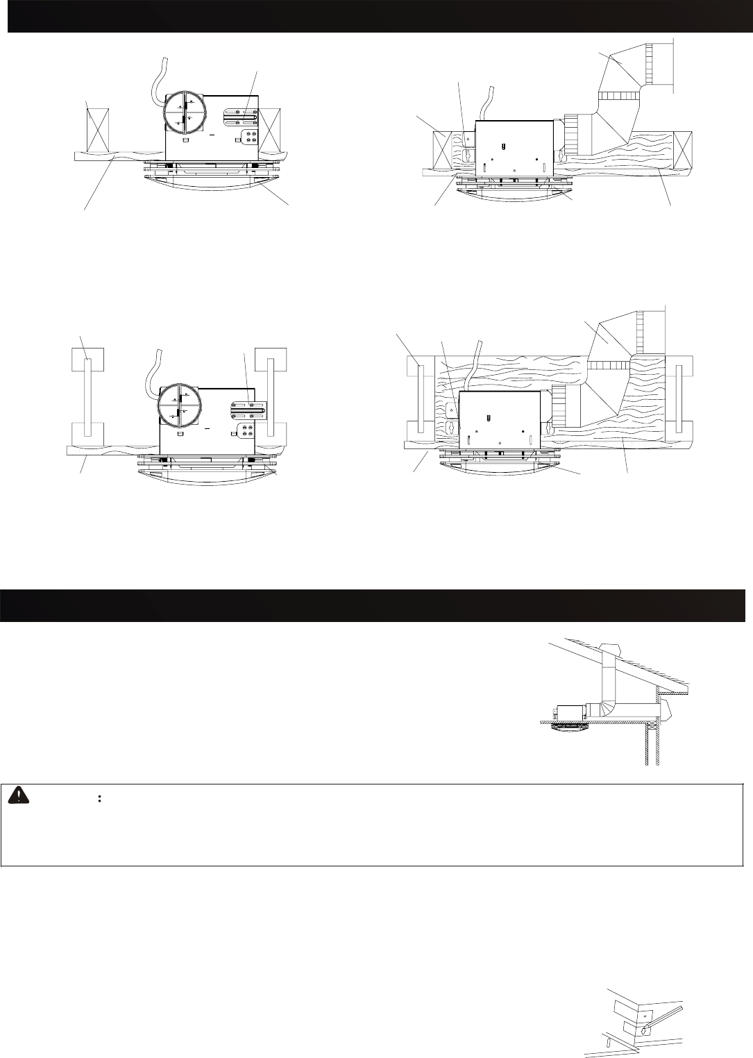
Fig.3
STEP.1:PLAN THE INSTALLATIONS
The unitoperates mostquietly andefficientlywhen located
where theshortest possibleduct runand minimumnumber of
elbows areneeded.(Fig.3)
Plan tosupply theunit withproper linevoltage andappropriate
power cable.
NOTE
THE FOLLOWINGINSTALLATION ILLUSTRATIONS SHOW2X6 JOISTS.IF YOUHAVEA
TRUSS OR"I"- JOISTINSTALLATION, MOUNTTHE VENTILATOR TOTHE ADDITIONAL
FRAMING INTHE SAMEMANNER.
STEP.2:INSTALL THEHOUSING
1. Choosethe locationfor yourfan inthe ceiling.For bestpossible performance,use the
shortest possibleduct runand aminimum numberof elbows.
2. Positionmounting bracketsagainst joistso thatbottom edgeof housingwill beflush
with finishedceiling.
Additional positioningfeature for1/2", 3/4",1", &1-1/4"thick ceilingmaterial:
Holes incorners ofhousing arelabeled withvarious ceilingmaterial
thicknesses. Positionhousingso bottomedge ofjoist isvisible through
a matchedset ofholes. Thehousing isnow inthe properposition for
that ceilingmaterial thickness.(Fig.4)
New Construction(attaching tojoist)
Fig.4
Page7
Page6
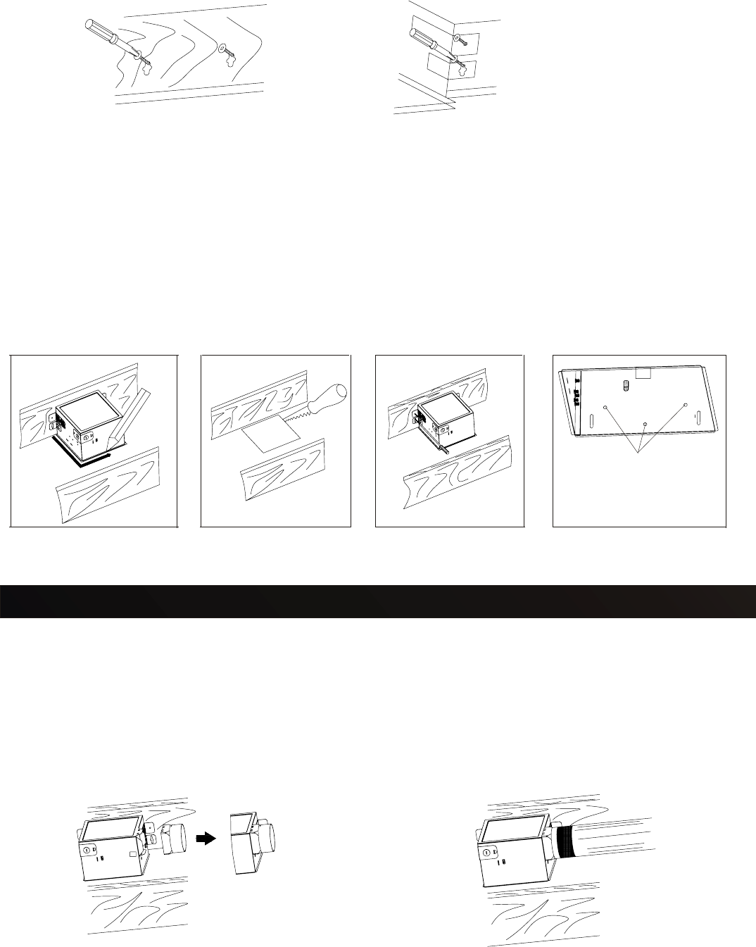
Existing Construction(accessible from above)
1. Choose the locationfor yourfan/light inthe ceiling. For bestpossible performance,use
the shortestpossible ductrun anda minimumnumber ofelbows.
2. Inattic, position mounting brackets against joist. Trace outline of housing on ceiling
material.(Fig.7)
3. Sethousing asideand cutceiling openingslightly larger thanmarked.(Fig.8)
4. Place housing in opening sothat itsbottom edgeis flushwith finishedceiling. Nailit to
joist throughkeyholes onboth sides. To ensurea noise-freeinstallation, driveanother
nail throughthe tophole ofeach mountingbracket.(Fig.9)
5. Additional mounting holes are provided for installations where access fromabove is
inconvenient ornot possible.Nail orscrew housingdirectly tojoists orframing.(Fig.10)
Fig.7 Fig.8 Fig.9 Fig.10
Additional
mounting holes
Fig.5 Fig.6
3. Sethousing asideand drivenails partiallyinto joistat thetop ofboth keyholemarks.(Fig.5)
4. Hanghousing fromnails andpound nailstight. To ensurea noise-freemount, pound
another nailthrough thetop holeof mountingbracket A.(Fig.6)
INSTALLATION(joist mounting)
Fig.11 Fig.12
STEP.3:INSTALL THEDUCTWORK
1. Attachdamper/duct connector
Snap thedamper/duct connectoronto housing.Make surethat tabson theconnector lock
into slotsin housing.Top ofdamper/duct connectormust beflush withtop ofhousing.(Fig.11)
2. Install4 inchround ductwork
Connect 4"round ductto damper/ductconnector andextend ductto outsidethrough aroof
or wallcap. Checkdamper tomake surethat itopens freely. Tape allduct connectionsto make
them secureand airtight.(Fig.12)
STEP.4:CONNECT WIRING
Run 120VAC housewiring toinstallation location,Use properUL Approvedconnector to
secure housewiring towiring plate.Refer towiring diagrambelow.Using wirenuts connect
house powerwires toventilating fanwires: blackto black;white towhite; greento green.
(Fig.13) Page8
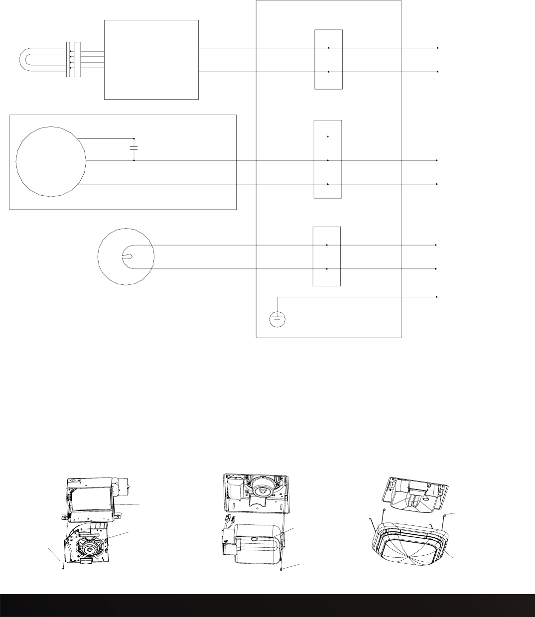
Fan unit
Wiring boxing
Motor
Blue
White
Black
White
Black
Green
Earth ground
Terminal
Condenser
Earth ground
White
Black
White
Black
White
Black
Power supply
AC120V 60HZ
Lamp
Night Lamp
Ballast
Terminal
Terminal
Power supply
AC120V 60HZ
White
Black
Power supply
AC120V 60HZ
Wiring diagram
Page9
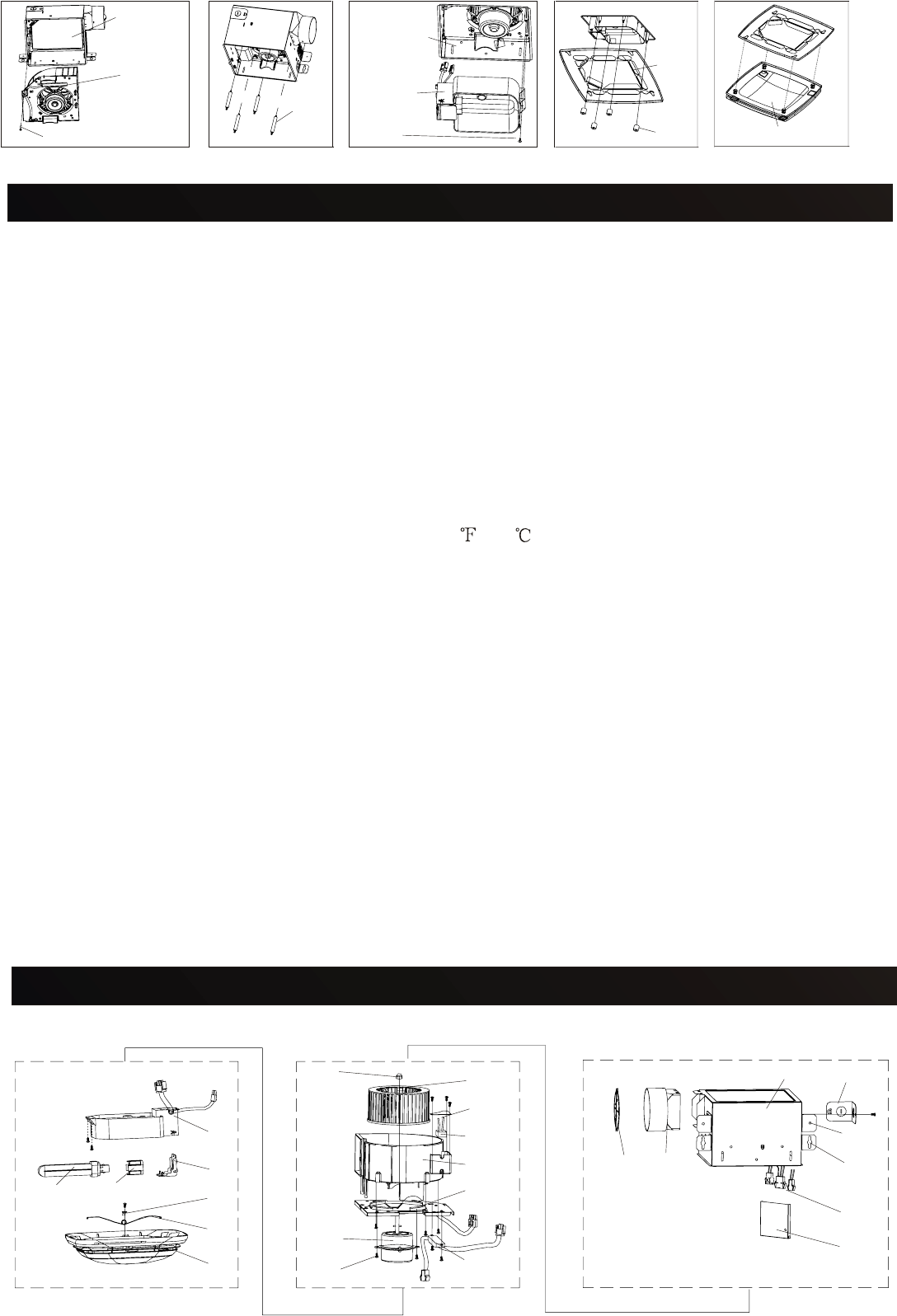
Fig.14 Fig.15
Housing
Motor unit
Screw
Grille
Fig.16
Lighting
unit
1.Install ceilingmaterial. Cutout aroundhousing.
2.Mounting themotor unitinto thehousing, andfastness withone M4x16screw.(Fig.14)
STEP.5:MOUNTING MOTORUNIT ANDATTACH THEGRILLE
3. Insertthe plugconnector intothe receptaclerespectively, andattach thelighting unitto
the fanunit with2 screws(M4X10) .
4. Insertthe fluorescentlamp andscrew thenight lampinto thelighting unit.
5. Squeezegrill springsand insertthem intoslot oneach sideof scroll.
Push grillagainst ceiling.
(Fig.15)
(Fig.16)
Screw
Spring
1.Install ceilingmaterial. Cutout aroundhousing.
2.Mounting themotor unitinto thehousing, andfastness withone M4x16screw.(Fig.17)
3.Screw thebolt intomotor plate.(Fig.18)
4. Insertthe plugconnector intothe receptaclerespectively, andattach thelight unitto the
fan unitwith 2screws (M4X10).(Fig.19)
5. Insertthe fluorescentlamps andscrew thenight lampinto thelight unit.
6. Locatethe grilleunit overthe fanhousing, Screwthe nutinto thebolt.(Fig.20)
7. Insertthe boltof Glasspanel tofour holesof themotherboard, pushthe panelin the
indicated direction,wedge thepanel tothe motherboard.(Fig.21)
STEP.5:MOUNTING MOTORUNIT ANDATTACH THEGRILLE
INSTALLATION(joist mounting)
a milddetergentsolution orglass cleanerand driedwith asoft cloth.Grille panunit maybe
gently vacuumedand wipedclean witha softcloth. Andwipe grillepan unitdry withnew cloth.
Never useabrasive cloth,steel woolpads orscouring powderson glassshade orgrille panunit.
Remove bulbsif necessary. Removedust anddirt onfan bodyusing avacuum cleaner. Using
a clothdampened withmild dishsoap, removeany dirtfrom fanbody.Wipe drywith newcloth.
Replace bulbs,grille panunit, glasspan anddecorative caps.
MAINTENANCE
The motoris permanentlylubricated andnever needsoiling. Ifthe motorbearings are
making excessiveor unusualnoises, replacethe motorwith theexact servicemotor. You
must replacethe impellerat thesame time.
REPLACEMENT OFLAMP
Remove decorativecaps andmachine screw(M4X12) fromgrille panunit, andremove
glass panelcarefully. Removegrille panunit fromfan body. Disconnectthe connectorsof
light unitfrom fanunit. Changethe 26Wfluorescent bulbor the4W incandescentlamp,
connect theconnectors andreplace grillepan unit,glass paneland decorativecaps.
Page10
Fig.17 Fig.18
Housing
Motor
unit
Screw
Lighting
unit
Bolt
Connector
Fig.19
Grille
pan
Nut
Fig.20
Glass panel
Fig.21
Screw
WARNING:
1.Disconnect powersource before workingon unit.
Routine maintenancemust bedone everyyear.
2.The lamp'sglass isfragile. Pleasehandle withcare. To removelamp, graspat baseand
move backand forceto loosen.
3.Do notpull hardon thelamp oryou maybreak theglass.
4.4W nightlamp hasthreaded base.Remove byturning counterclockwise.The glasspanel
is fragile.Remove itwith care.
CAUTION:
1. Neveruse petrol,benzene, thinneror anyother suchchemicals forcleaning theventilating
fan.
2. Donot allowwater toenter motor.
3. Metaland electricalparts shouldnever beimmersed inwater.
4. Donot immerseresin partsin waterover 140 (60 ).
CLEANING
Remove decorativecaps andmachine screw(M4X12) fromgrille panunit, andremove glass
panel carefully. Removethe grillepan unitfrom fanbody.Glass shadecan bewiped cleanwith
CLEANING &MAINTENANCE
12
3
45
6
7
8
910
11
12
13
14
15
16
17
18
19
20 21 22
23
24
SERVICE PARTS(V50L/V70L/V80L/V90L/V100L/V110L)
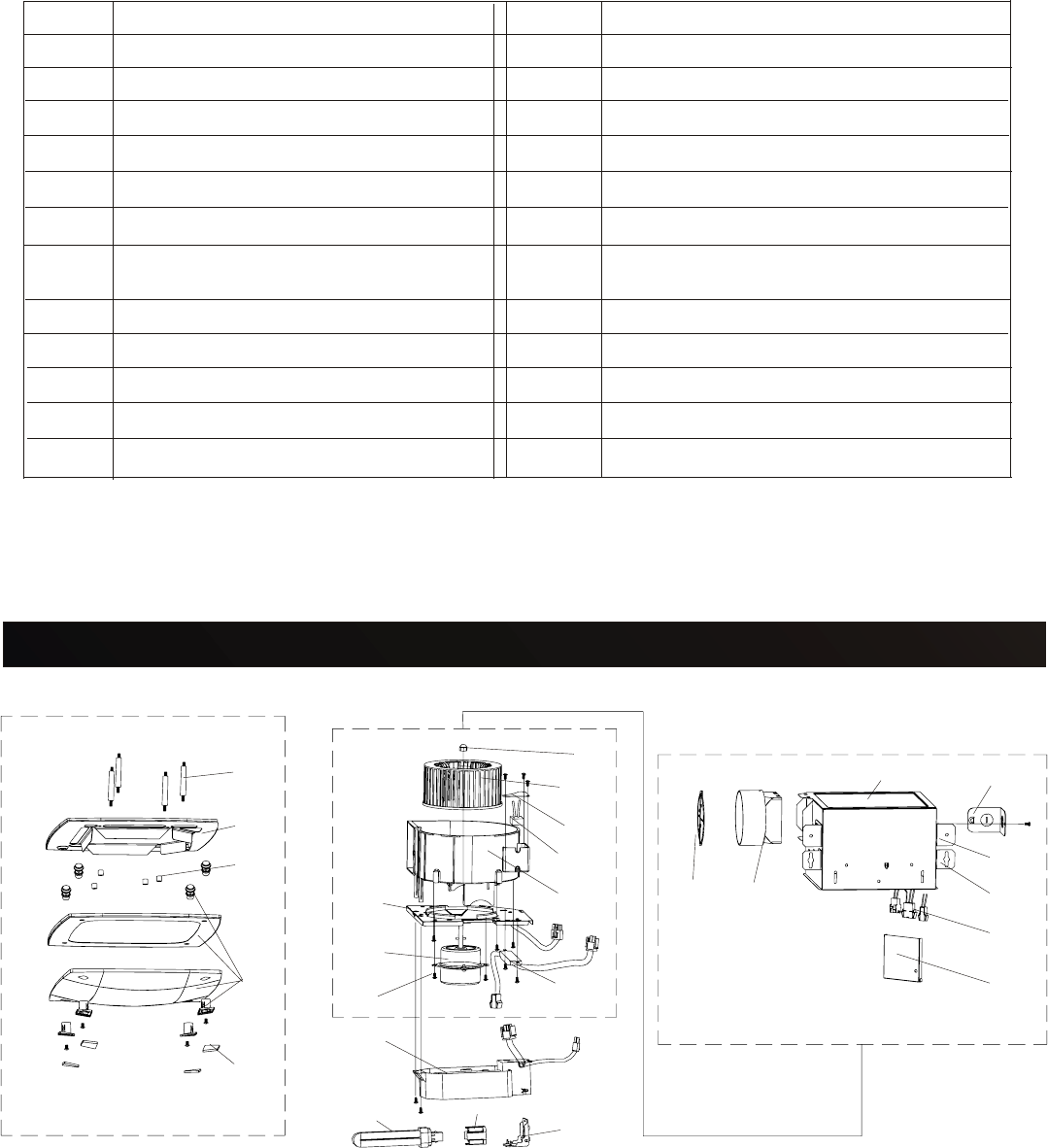
No. Part name No. Part name
1
2
3
4
5
6
7
8
9
10
11
12
13
14
15
16
17
18
19
20
21
22
23
24
Housing Motor support
Outlet cover Ballast
Mounting BracketA Motor
Mounting BracketB
Screw
Adaptor Reflecting coverunit
Damper Compact FluorescentLamp
setting bracket
Female pinconnector
Compact FluorescentLamp
Wiring cover Lamp holder
Blower Wheelsetting nut
Blower Wheel Spring hook
Condenser boxcover
Condenser
Casing
These instructionsmay beprinted inEnglish ("theEnglish version")and oneor moreother
languages ("otherversions"), inwhich casethe Englishversion shallprevail ifthere isany
inconsistency betweenthe Englishversion andany oneor moreof theother versions.
Grille spring
Grille
3
45
6
7
8
12
13
14
15
16
17
18
19
20 21
24
25
26
12
9
10
11
22
23
SERVICEPARTS(DV50L/DV70L/DV80L/DV90L/DV100L/DV110L)
Page11

Page12
No. Part name No. Part name
1
2
3
4
5
6
7
8
9
10
11
12
13
14
15
16
17
18
19
20
21
22
23
24
25
26
Housing Motor support
Outlet cover Ballast
Mounting BracketA Motor
Mounting BracketB Screw
Adaptor Reflecting coverunit
Damper Compact FluorescentLamp
setting bracket
Female pinconnector Compact FluorescentLamp
Wiring cover Lamp holder
Blower Wheelsetting nut Bolt
Blower Wheel Grille pan
Condenser boxcover Nut
Condenser Glass panelunit
Casing Decorative cap
These instructionsmay beprinted inEnglish ("theEnglish version")and oneor moreother
languages ("otherversions"), inwhich casethe Englishversion shallprevail ifthere isany
inconsistency betweenthe Englishversion andany oneor moreof theother versions.

Page13
LONON USA,LLC
LIMITED WARRANTY
ProductName: ModelNumber:
Date ofpurchase: Dealer:
Date ofinstallation: Builder/Installer:
WarrantyPeriod (fromdate oforiginal purchase)("WarrantyPeriod"): Five(5) yearsfor the
motor; One(1) yearfor otherparts.
LIMITED WARRANTY. Lonon USA,LLC ("LONON")gives thislimited warranty("this Warranty")
to theoriginal purchaserof theProduct ("Buyer"),subject tothe followingterms: LONONwarrants
that theProduct willbe freefrom originaldefects inmaterials andworkmanship forthe Warranty
Period, PROVIDED(i) thatthe Producthas beenproperly stored,installed, serviced,maintained
and operated;(ii) thatthe Producthas notbeen lteredor repaired inany waywhich, inLONON's
reasonable judgment,will affectits performanceor eliability;and (iii)that theProduct hasnot
been improperlyinstalled orsubjected tomisuse, negligence,or accident,or incorrectlyused
in combinationwith otherarticles. Savewhere provided otherwisein thisWarranty,Buyer assumes
all risksand liabilityfor resultsof useof theProduct. Where applicable,warranties onpurchased
parts arelimited tothe termsof thewarranties extendedby LONON'ssupplier(s). Without
prejudice tothe limitationsand exclusionsbelow, THIS WARRANTYSHALL BEVALIDONLY
IF THEPRODUCT ISPURCHASED ANDINSTALLED INTHE UNITEDSTATES.
WARRANTY SERVICE. Allclaims underthis Warranty shallbe madein writingand delivered
to LONONat theaddress setout belowwithin 15days afterdiscovery ofthe defectand prior
to theexpiration ofthe Warranty Period.Buyer shallbe barredfrom anyremedy ifBuyer fails
to makesuch claimwithin suchperiod. Within30 daysafter receiptof atimely claim,LONON
shall havethe optioneither toinspect theProduct whilein Buyer'spossession orto request
Buyer toreturn theProduct toLONON atBuyer's expensefor inspectionby LONON.Subject
to theterms ofthis Warranty,LONON will,during theWarrantyPeriod, atits optionreplace or
repair, freeof charge, theProduct orpart thereofwhich LONONdetermines isdefective under
normal useand maintenance.
This Warranty doesnot coverand LONONis notresponsible for: (i)normal maintenance
and service;(ii) anyProduct whichhas beensubjected tomisuse, impropermaintenance or
modification, neglect,electrical currentfluctuations, negligence,accident, improperor faulty
operation orinstallation orinstallation contraryto theinstallation instructions,use ofparts or
supplies otherthan LONON'sthat causedamage tothe Product,defacement, alteration,or
removal ofa productserial number;(iii) thecost ofremoval ofthe defectiveProduct orpart,
damages dueto removal,or anyexpenses incurredin shippingthe defectiveProduct orpart
to orfrom LONON'sservice centre,or theinstallation ofthe repaired orreplacement product
or part;(iv) anyglass component,light bulb,fluorescent lamp,starter, tube,filter, duct,roof
cap, wallcap orother ductingaccessories evenwhere theProduct isequipped withany ofthe
same.
Subject tothe abovewarranty,to themaximum extentpermitted byapplicable law:
(i) LONONand itssuppliers providethe Productas isand herebydisclaim allother warranties
and conditionswhether expressimplied orstatutory,including withoutlimitation implied
warranties orconditions ofmerchantability andof fitnessfor aparticular purpose,and any
responsibility forany lossof revenuesor profits,inconvenience, expensefor substitute
equipment orservice, storagecharges,or lossor corruptionof data;
(ii) implied warranties,when applicable,shall commenceupon thesame dateas theexpress
warranty providedabove,and shall,except forwarranties oftitle, extendonly forthe durationof
the expresswarranty above;
(iii) LONONassumes noliability onaccount ofany recommendations,opinions oradvise as
to thechoice, installationor useof theProduct, andany suchrecommendations, opinionsor
advice givenare acceptedat theoriginal purchaser'sown riskand shallnot constituteany
warranty orguarantee concerningany matter;
WARRANTY

WARRANTY
(iv)
in
no
event shall LONON
and
its
suppliers be
liable
for
any
special, incidental, punitive,
indirect, or
consequential
damages whatsoever
arising
out of
or
in
any
way related
to
the
use
of
or
inability
to
use
the
Product for
whatever
reason
and based on
whatever
cause
of
action;
(v)
the
entire
liability
of
LONON
and
its
suppliers
in relation
to
the manufacture and
supply
of
the
Product
is
limited
to
the amount actually
paid
by
the
original purchaser
for
the
Product.
Damages
are
limited
to
the
purchase
price
of
the
Product.
This W
arranty
gives
the
Buyer
specific
legal
rights.
Some
states
do not
allow
limitation
on
how
long
an
implied
warranty lasts,
or
exclusion
of
or limitation
on incidental
or
consequential
damages.
The
extent
to
which
the
above
limitations
and exclusions
are
valid may
vary
from
state
to
state.
No
agent,
deale
r, employee
or
other person
is authorized
to
give
any
other
warranties
or
assume
any
other liability on LONON's
behalf in
connection
with
the
Product except
in
writing
signed
by
an
authorized
officer
of
LONON.
Notwithstanding
any
past
practice
or
dealings
or
any
custom
of
the trade, the
supply
of
the
Product
does
not
include the provision
of
any
technical advice
or
system design,
which
may
be
provided at
LONON's
sole
option
and
subject
to
additional
charges.
This
Warranty
may
be
printed
in
English
("the
English
version")
and
one
or
more
other
languages
("other
versions"),
in
which
case
the
English
version shall prevail
if
there
is
any
inconsistency between the
English
version
and
any
one
or
more
of
the other
versions.
FOR
ASSIS
T
ANCE:
PLEASE
CON
T
ACT
Lonon
USA,
LLC
Customer
Service
Centre:
4320 Winfield Road, Suite 200
Warrenville,
IL
60555
Opening hours:
Mon.
-
Fri.
(except
public
holidays):
8:00 am
to
3:30
pm
T
oll
free
service
hotline:
1-888-566-6687
IMPOR
T
AN
T
:
The
original
invoice
for
the
purchase
of
the
Product
together
with
this
warranty
card must
be presented
in
order
to
qualify
for
service
under
this
W
arranty.
Page11
Version:A Revision Data: 12/14/2005
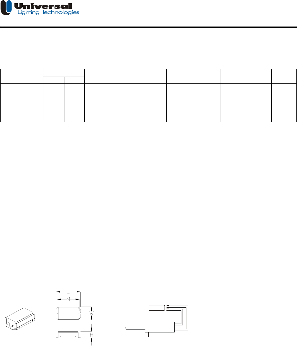
Description: Electronic ballast for compact fluorescent Lamp (1) Quad 4pin 26W or (1) TwinT5 4pin 24W or (1)T5 linear 24W
• Line Voltage : 120Vac, 60Hz • Rapid Start
• Lamp Connection: Single Lamp WS-1
Input Power Crest
Volts Freq-Hz Watts* Factor Factor
27
25
24
*ANSI measured wattage,25ć ambient,benchtop,lamps base up ; Enclosed fixture, wattage may change depending on fixture type.
**Lamp Type: Quad 4pin T4
Application and Performance Specification Information Subject to Change without Notification.
Performance: Safety:
• Meets ANSI Standard C82.11-1993 • No PCB's
• Meets ANSI Standard C62.41-1991 • UL listed (Class P)
• Meets UL 935 • UL # 221323
• Meets FCC Part 18 (Class B) for EMI
• Operating Frequency Range: 45-55 kHz
• Abnormal Protection Circuit
• End of lamp life protection Circuit
• Auto-Reset Shutdown Circuit
- lamp(s) should be replaced at end of lamp life
- Lamp relights upon insertion in socket
Application: Physical Parameters
• Minimum Starting Temperature: 5° F (-15° C) Case: CM-31(#90-5B)
• Maximum Ambient Temperature: 122° F(50° C) Overall Length(L): 3.86"(99mm)
• Maximum Case Temperature (@ tc): 158° F(70° C) Width(W): 2"(52mm)
• Sound Rated: A Mounting(M): 3.5"(90mm)
Height(H): 1.00"(25.4mm)
Weight: 0.55bs(0.25kg)
Qty/Carton: 30
Color: Black/White
Can Material: Metal
Black 320mm
Wire length: White 300mm
(±25.4mm) Blue 240mm*2
Red 240mm*2
Install in accordance with
the National Electrical Code Ballast must be grounded.
FCC NOTE:
The manufacturer is not responsible for any radio or TV interference caused by unauthorized modifications to this equipment. Such modificatio
n
could void the user's authority to operate the equipment.
This product may cause interference to radio equipment and should not be installed near maritime safety communications equipment or other
critical navigation or communication equipment operating between 0.450-30MHz.
Warranty:
Universal Lighting China warrants to the purchaser that each electronic ballast will be free from defects in material or
workmanship for a period of 3 years from date of manufacture when properly installed and under normal conditions of use.
Call 8621-64808118*218,128 for technical assistance.
ƻƻƻƻƿƿ Manufactured in China
#90-5B120 60CBT-126L-120S 1 0.56 <1.7
0.32
CBT-126L-120S
APPLICATION and PERFORMANCE SPECIFICATION
Line Case ULC #
No.of
lamps
Model Nominal
Line Amps
Lamp
Type**
T5 linear 24W
26W/8T4/Q/G24q-3
(Quad 4pin/PL-C 26W)
24-27W/13T5/T/2G11/PH-RS
(Twin T5 4pin/PL-L 24W)
0.39
0.37
BALLAST
Red
Blue
White
Black