HAOLIYUAN R0300 802.11n Wireless Router User Manual WR8196 Manual
HAOLIYUAN (SHENZHEN) ELECTRONIC CO., LTD 802.11n Wireless Router WR8196 Manual
User manual

1 / 21
802.11n Wireless Router
R0300/WR366E
V1.0
User Manual

2 / 21
Chapter 1. Introduction
Thank you for choosing the Wireless Router. This router provides dedicated
solution for Small Office/Home Office (SOHO) networks. your local wired or
wireless network can share Internet access, files and fun for multiple PCs
through one ISP account. It is an easy Web-based setup for installation and
management. Even though you may not be familiar with the router, this guide
will make configuring the router easy. Before installing the router, please look
WKURXJKWKLVJXLGHWRNQRZDOOWKHURXWHU¶VIXQFWLRQV
1.1 Product Features
ƹ
Includes Wireless AP, Router, 4-Port Switch, and Firewall in one
ƹ
Supports WPS (Wi-Fi Protected Setup) encryption method
ƹ
Complies with IEEE 802.11n, IEEE 802.11g, IEEE 802.11b, IEEE 802.3 and IEEE 802.3u
standards
ƹ
Supports 64/128-bit WEP, WPA, WPA2, WPA&WPA2 encryption methods
ƹ
Provides one 10/100Mbps Auto-Negotiation Ethernet WAN port
ƹ
Provides four 10/100Mbps Auto-Negotiation Ethernet LAN ports
ƹ
Supports xDSL/Cable MODEM, static and dynamic IP in community networking
ƹ
Supports Auto MDI/MDIX
ƹ
Supports LAN access control over Internet connection
ƹ
Supports WDS wireless network extension
1.2 Package contents
The following contents should be found in your box:
One Wireless Router
One power adapter for Wireless Router
Quick Installation Guide
Note: If any of the listed contents are damaged or missing, please contact the retailer from
whom you purchased the product for assistance.
3 / 21
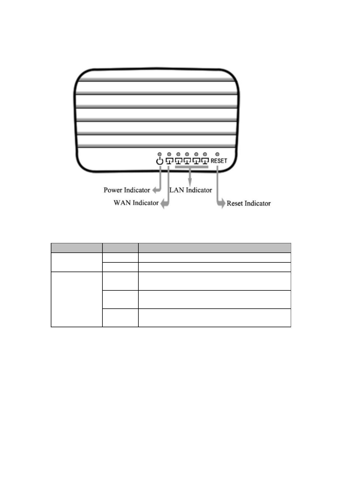
1.3 Led Indicator and port description
The LED indicators displayed on the front panel, the status of these LED
LQGLFDWRUV UHSUHVHQW WKH GHYLFH¶V ZRUNLQJ FLUFV )RU GHWDLOV SOHDVH UHIHU WR
below:
Name Status Description
Power off No Power
on Power on
WAN/
LAN(1-4)
off There is no device linked to the corresponding
port
on Connected to a device through the corresponding
port
Flash Sending or receiving data over corresponding
port
4 / 21
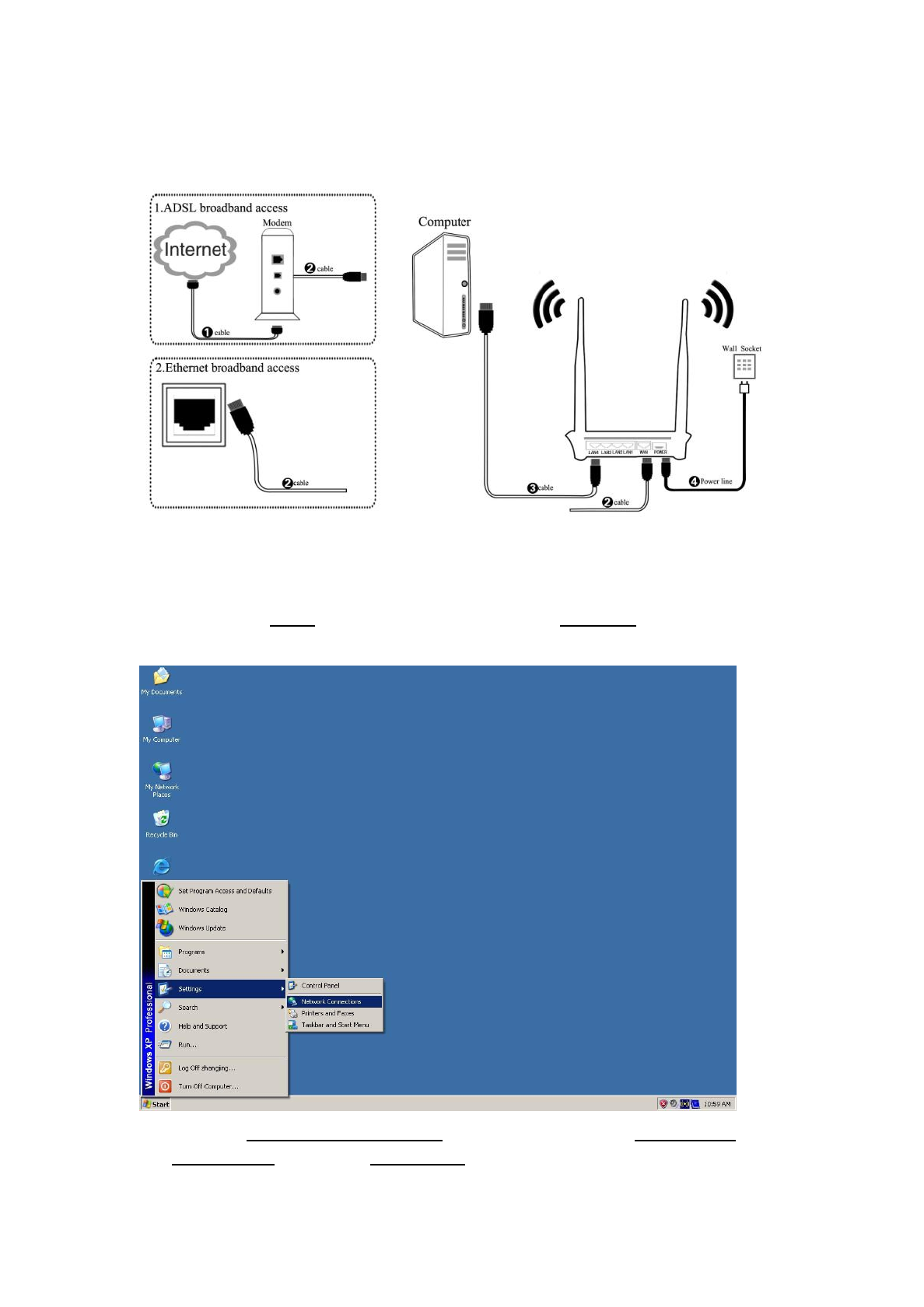
Chapter 2. Installation Preparation
2.1 Connecting the Router
2.2 Configure Computer
Follow the instructions below to configure a computer running Windows XP:
2.2.1 From the Start menu on your desktop, go to Settings, and then click on
Network Connections.
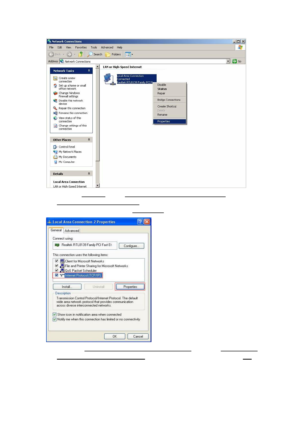
2.2.2 In the Network Connections window, right-click on Local Area
Connection, then click Properties.
5 / 21
2.2.3 In the General tab of Local Area Connection Properties, Click
Internet Protocol (TCP/IP) XQGHU³7KLVFRQQHFWLRQXVHVWKHIROORZing
LWHPV´ Then click on the Properties button.
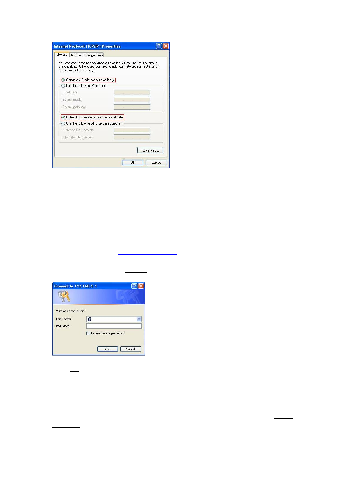
2.2.4 6HOHFW³Obtain an IP address automatically´DQGWKH³Obtain DNS
server address automatically´by clicking the radio-button. Click OK .
6 / 21
Chapter 3. Installation Guide
This User Guide recommendV XVLQJ WKH ³4XLFN ,QVWDOODWLRQ *XLGH´ IRU
first-time installation, For advanced users, if you want to know more about this
device and make use of its functions adequately, you need to read this chapter
and configure advanced settings though the Web-based Utility.
3.1 Login the Router
Input the website http://192.168.1.1 in Internet explorer address column,
User should see the login page, input the user name and password (default user
QDPHDQGSDVVZRUGLV³admin´ORJin windows as below:
FOLFN³ok´EXWWRQHQWHUWKHmain page
After your successful login, you can configure and manage the device. There
are main menus on the left of the web-based utility. Submenus will be available
after you click one of the main menus. On the right of the web-based utility,
there are the detailed explanations and instructions for the corresponding page.
To apply any settings you have altered on the page, please click the Apply
changes button.
7 / 21
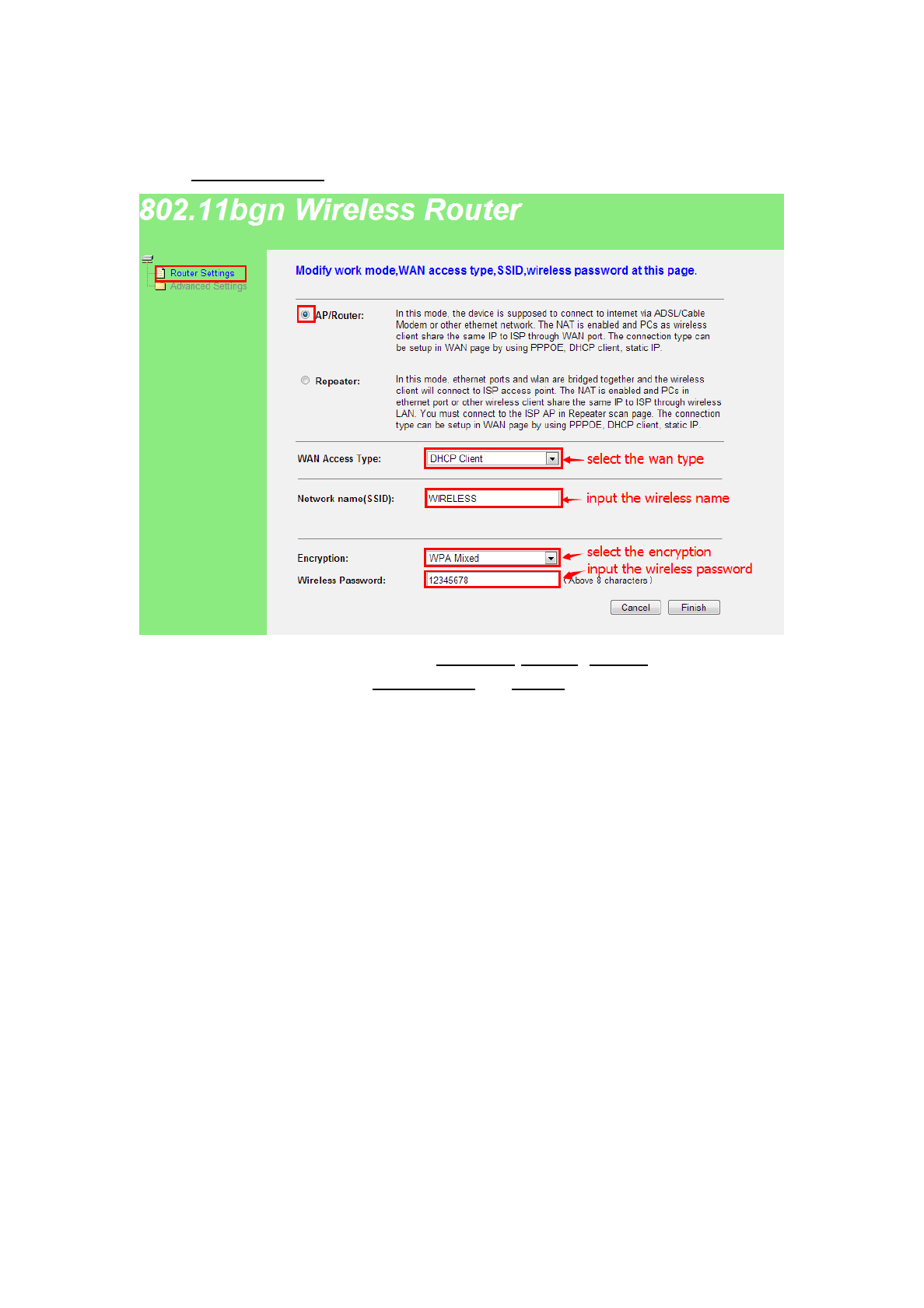
3.2 Quick Installation Guide
&OLFN³Router Setting´menu then show quick Installation window:
WAN Access Type: you can select Static IP, DHCP, PPPoE;
Encryption: you can select WPA Mixed and None;
8 / 21
3.3 Advanced setup
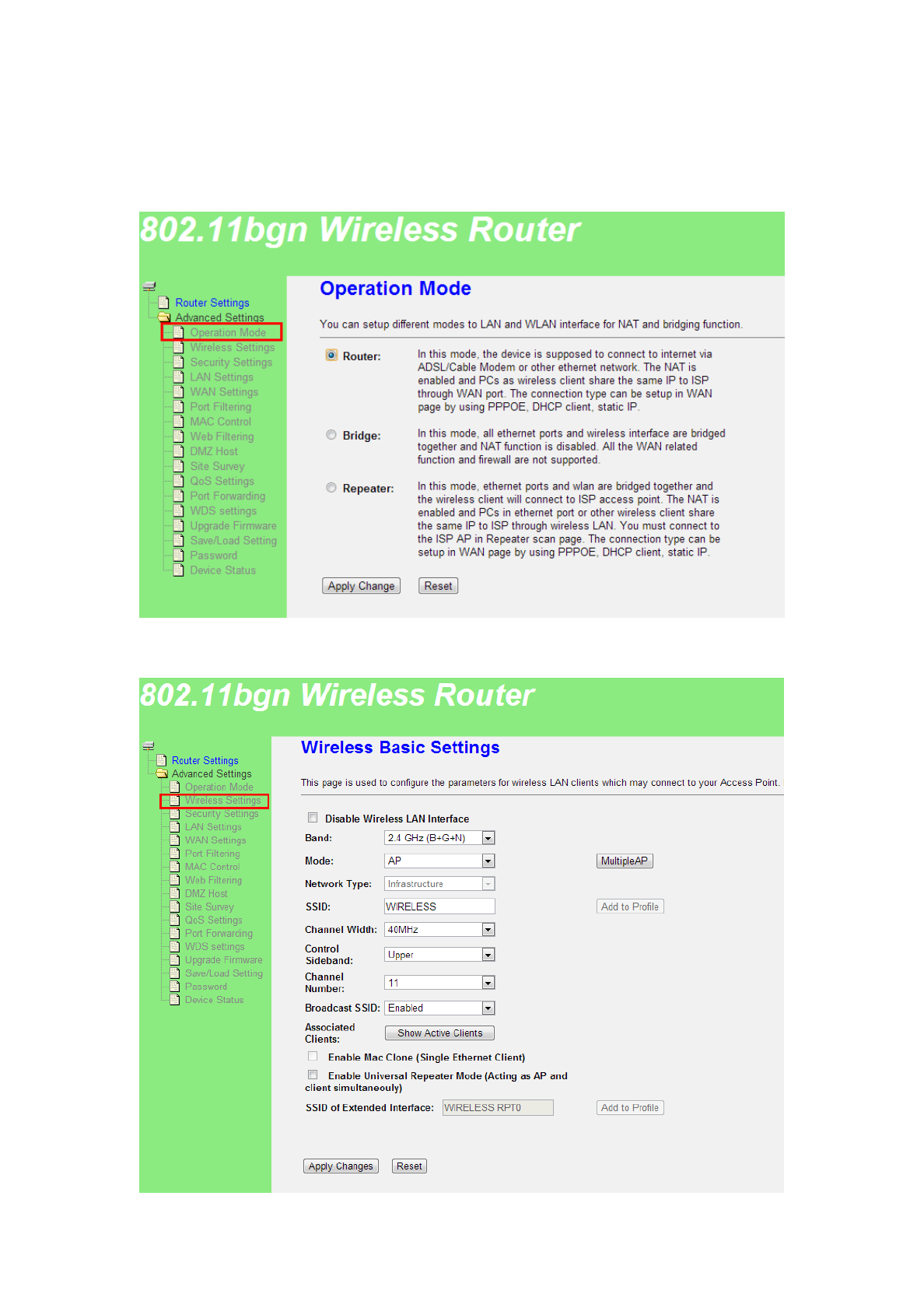
3.3.1 Operation Mode
3.3.2 Wireless Settings

9 / 21
Disable wireless LAN Interface : Close wireless function .
Band : you can select as below:
2.4G Hz(B):11b mode, rate is 11 Mbps
2.4G Hz (G):11g mode, rate is 54 Mbps
2.4G Hz(N):11n mode, rate is 150 Mbps(1T1R)300 Mbps(2T2R)
2.4G Hz (B+G):11b/g mode, rate is 11 Mbps and 54 Mbps
2.4G Hz(G+N):11g/n mode, rate is 54 Mbps,150 Mbps /300 Mbps
2.4G Hz(B+G+N):11b/g/n mode, rate is 11 Mbps,54 Mbps,150 Mbps
/300 Mbps
Mode: Can select one of AP,CLIENT,WDS,AP+WDS
Network Type : default is infrastructure, when Mode is Client , you also can
set it to Ad-hocDŽ
SSID: Wireless LAN status authentication name ,User can access the wireless
networking through status authentication name only .
Channel Width: you can select 20MHz and 40MHz.
Channel Sideband: you can select Upper or Lower. default is Upper .
Channel Number : the current channel router used.
Broadcast SSID: you can select Disable or Enable. default is Enable.
Associated clients &OLFN³Show Active Clients´EXWWRQLWZLOOVKRZ³$FWLYH
:LUHOHVV&OLHQW7DEOH´<RXFDQVHHWKHFOLHQW¶VVWDWXV
Enable Mac Clone (Single Ethernet Client): Enable Mac Clone.
Enable Universal Repeater Mode (Acting as AP and client
simultaneously): Enable Universal Repeater Mode.
SSID of Extended Interface: Only when the Enable Universal Repeater Mode
is available.
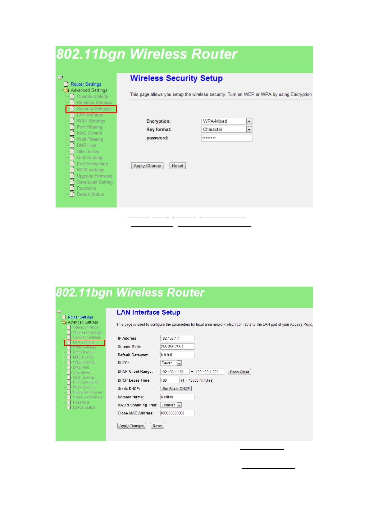
3.3.3 Security Settings
This page allows you setup the wireless security. Turn on WEP or WPA by
using Encryption Keys could prevent any unauthorized access to your wireless
network.
10 / 21
Encryption: Support None ,WEP ,WPA2 ,WPA2 Mixed.
Key Format: Support Passphrase ,Hex (64 characters)
password : input 8~128 characters password.
3.3.4 LAN Settings
This page is used to configure the parameters for local area network which
connects to the LAN port of your Router. Here you may change the setting for IP
address, subnet mask, DHCP, etc..
IP Address: WKH URXWHU¶V /$1 ,3 DGGUHVV GHIDXOW LV 192.168.1.1,you can
according request to change it .
Subnet Mask: WKHURXWHU¶V/$1VXEQHWPDVNGHIDXOWLV255.255.255.0
11 / 21
Default Gateway: WKHURXWHU¶VGHIDXOWLV0.0.0.0,you can according request to
change it.
DHCP: you can select one of Server,Disable,Client. Default is Server .that
the DHCP Server can configure the TCP/IP protocol of your LAN
computer automatically. For the Server mode, it must fill in the DHCP
client address range.
DHCP Client Range: default is 192.168.1.100-192.168.1.200. Click to
show client button to display the DHCP client information.
Domain Name: default is Realtek.
802.1d spanning tree: you can select Disable or Enable. default is Disable.
Clone MAC Address: you can input a MAC address for use clone function.
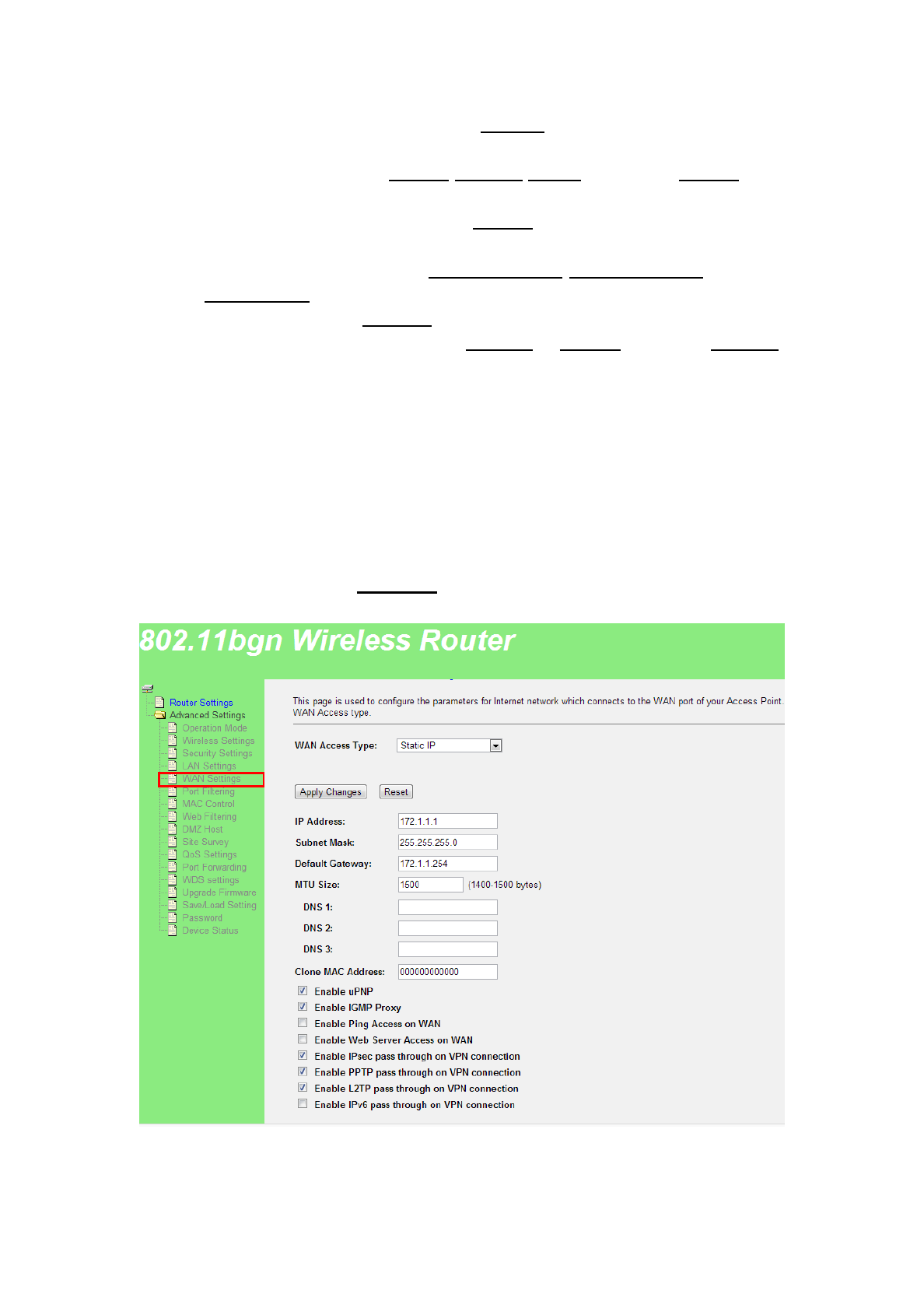
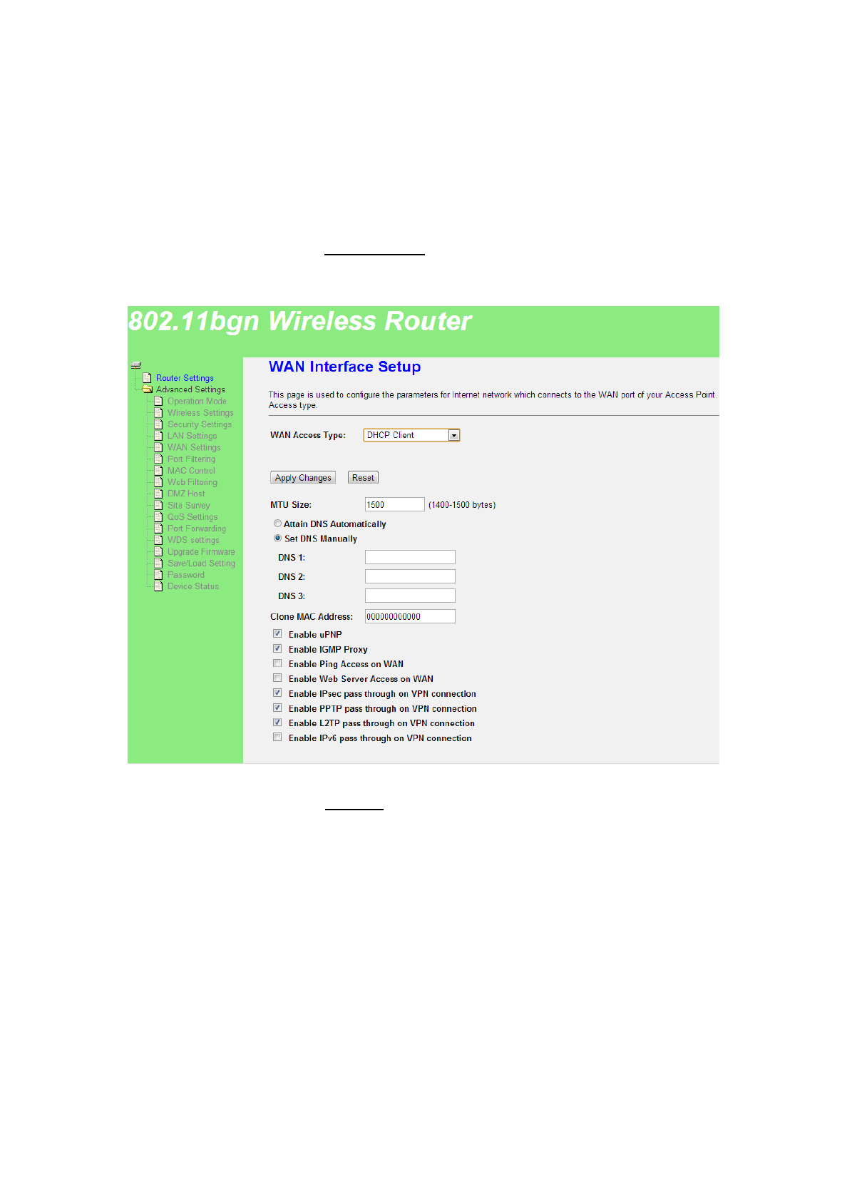
3.3.5 WAN Settings
This page is used to configure the parameters for Internet network which
connects to the WAN port of your Access Point. Here you may change the access
method to Static IP, DHCP, PPPoE by click the item value of WAN Access
type.
A. Static IP
If your access type is Static IP, It means you have static IP address ISP
supply, so you need to fill in follow details:
IP address7KHURXWHU¶V:$1,3DGGUHVVWKDWWKH,63VXSSO\,I\RXQRWVXUH
can check with ISP.
12 / 21
Subnet Mask 7KH URXWHU¶V VXEQHW PDVN WKDW WKH ,63 VXSSO\ QRUPDOO\ LW LV
255.255.255.0.
Default Gateway: Fill in yours gateway that the ISP supply, if you not sure can
check with ISP.
B. DHCP Client
If your access type is DHCP Client, then you can get the IP address from
the ISP. it means you only need connect the ISP line with internet to the router¶s
WAN port. You do not need to enter the information like other modes.
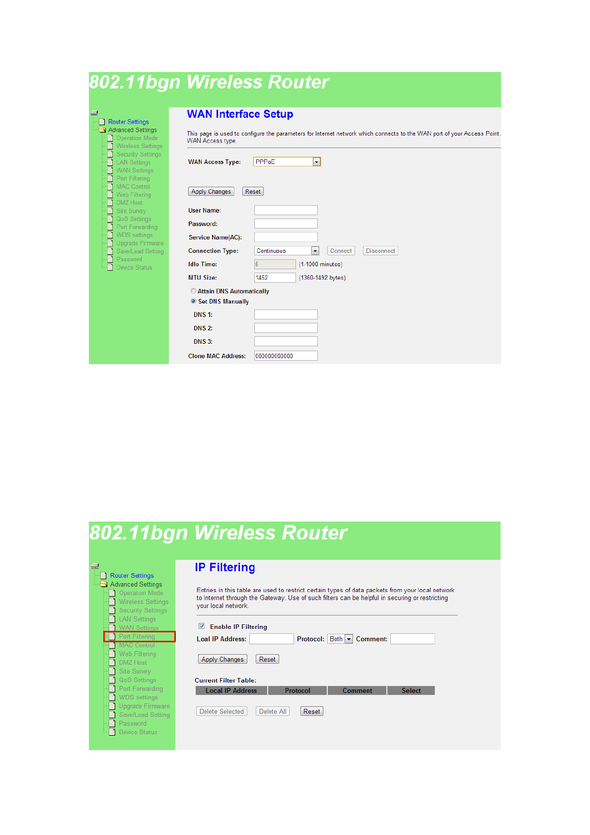
C. PPPoE
If your access type is PPPoE, with ADSL virtual dialing, you need to fill in
following details:
13 / 21
User Name: Fill in ADSL access user name which supply by ISP, if you not sure
can check with ISP.
password: Fill in ADSL access password which supply by ISP, if you not sure
can check with ISP.
3.3.6 Port Filtering
Entries in this table are used to restrict certain types of data packets from
your local network to Internet through the Gateway. Use of such IP filters can be
helpful in securing or restricting your local network.

14 / 21
Enable IP Filtering :Open IP address filtering function.
Local IP Address : Input filtering IP address , as 192.168.1.12 .
Protocol : select the protocol type for the controlled data.
Current Filter Table : display current IP filtering table .
3.3.7 MAC Control
If you choose 'Allowed Listed', only those clients whose wireless MAC
addresses are in the access control list will be able to connect to your Access
Point. When 'Deny Listed' is selected, these wireless clients on the list will not be
able to connect the Access Point. Default is disable.
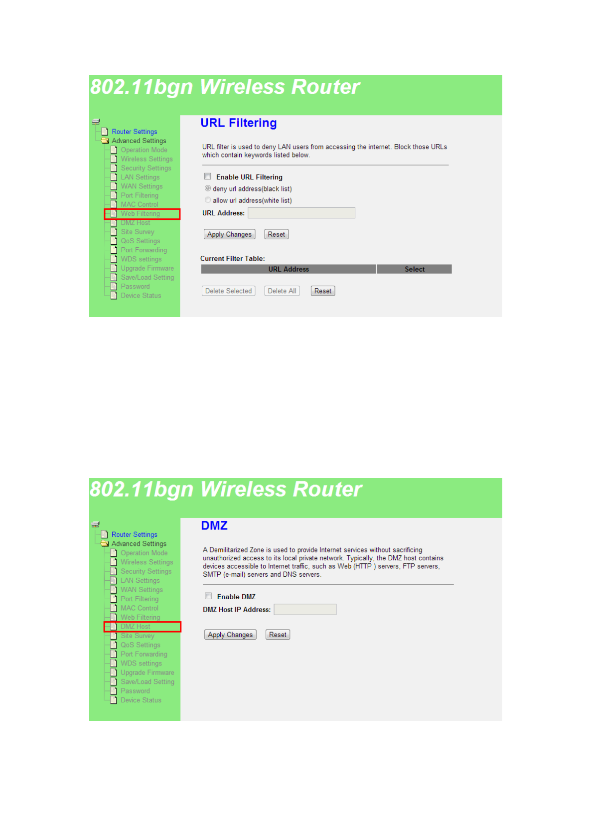
3.3.8 Web Filtering
Web filter is used to deny LAN users from accessing the internet. Block those
URLs which contain keywords listed below.
15 / 21
Enable URL Filtering : Open URL filtering function .
URL Address : Input the filtering URL address.
Current Filter Table :display current URL filtering table .
3.3.9 DMZ Host
A Demilitarized Zone is used to provide Internet services without
sacrificing unauthorized access to its local private network. Typically, the DMZ
host contains devices accessible to Internet traffic, such as Web (HTTP ) servers,
FTP servers, SMTP (e-mail) servers and DNS servers.
Enable DMZ: Open DMZ function .
DMZ Host IP Address : Input DMZ host IP address.
16 / 21
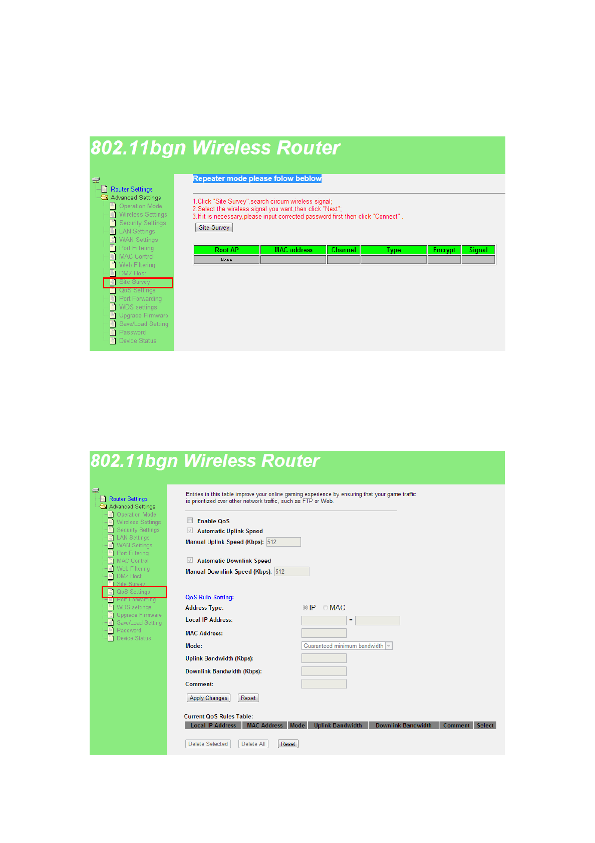
3.3.10 Site Survey
This page provides tool to scan the wireless network. If any Access Point or IBSS
is found, you could choose to connect it manually when client mode is enabled..
3.3.11 QoS Settings
Entries in this table improve your online gaming experience by ensuring
that your game traffic is prioritized over other network traffic, such as FTP or
Web.
17 / 21
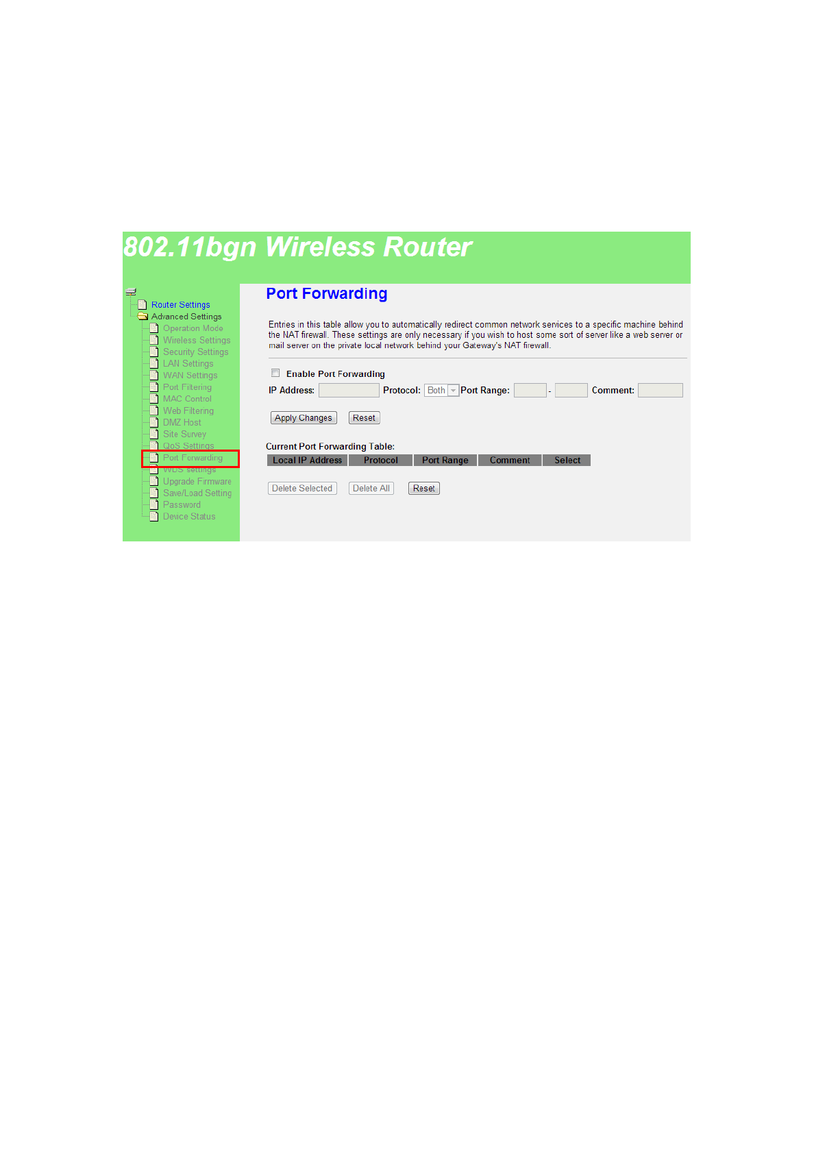
3.3.12 Port Forwarding
Entries in this table allow you to automatically redirect common network
services to a specific machine behind the NAT firewall. These settings are only
necessary if you wish to host some sort of server like a web server or mail server
on the private local network behind your Gateway's NAT firewall.
Enable Port Forwarding: open port forwarding function
IP Address: Local IP Address
Port Range: input forwarding port range ,as 22-120 .
Protocol : select the protocol type for the controlled data.
Current Port Forwarding Table :display current port forwarding table .
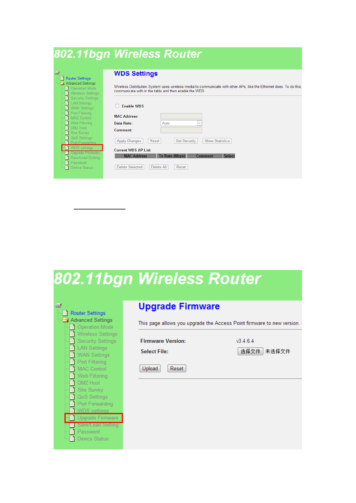
3.3.13 WDS Settings
Wireless Distribution System uses wireless media to communicate with
other APs, like the Ethernet does. To do this, you must set these APs in the same
channel and set MAC address of other APs which you want to communicate with
in the table and then enable the WDS.
18 / 21
$W³Wireless´±!³Basic settings´SDJH6HWMode to WDS or AP+WDS
type , and Enable WDS at WDS Settings page , fill in tKH:'6$3¶V0$&DGGUHVV
&OLFN³Apply Changes´EXWWRQWRILQLVKVHWWLQJ
3.3.14 Upgrade Firmware
This page allows you upgrade the Router firmware to new version. Please
note, do not power off the device during the upload because it may crash the
system.
19 / 21
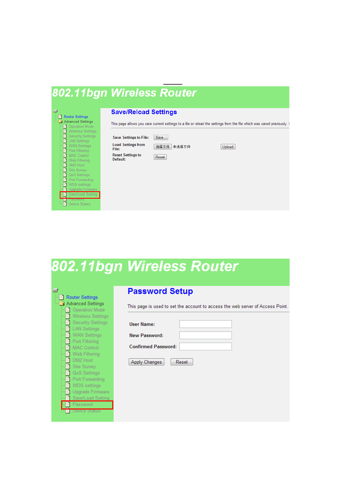
3.3.15 Save/Reload Settings
This page allows you save current settings to a file or reload the settings
from the file which was saved previously. Besides, you could reset the current
configuration to factory default(click Reset button).
3.3.16 Password
This page is used to set the account to access the web server of Router.
Empty user name and password will disable the protection.
20 / 21
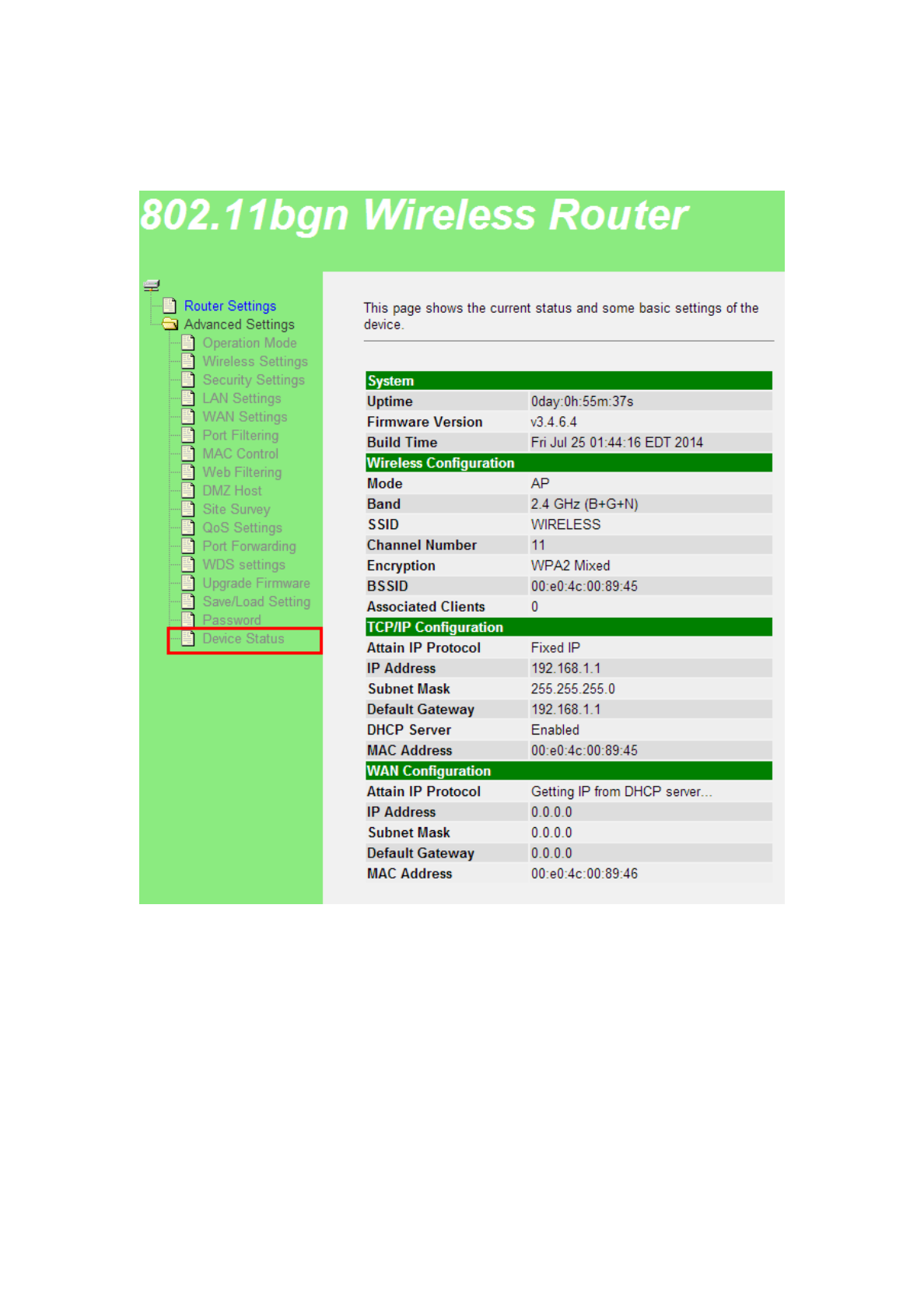
3.3.17 Device Status
This page shows the current status and some basic settings of the device.

21 / 21
This device complies with Part 15 of the FCC Rules. Operation is subject to the following two
conditions: (1) this device may not cause harmful interference, and (2) this device must
accept any interference received, including interference that may cause undesired operation.
Changes or modifications not expressly approved by the party responsible for compliance
could void the user's authority to operate the equipment.
NOTE: This equipment has been tested and found to comply with the limits for a Class B
digital device, pursuant to Part 15 of the FCC Rules. These limits are designed to provide
reasonable protection against harmful interference in a residential installation. This
equipment generates, uses instructions, may cause harmful interference to radio
communications. However, there is no guarantee that interference will not occur in a
particular installation. If this equipment does cause harmful interference to radio or television
reception, which can be determined by turning the equipment off and on, the user is
encouraged to try to correct the interference by one or more of the following measures:
-- Reorient or relocate the receiving antenna.
-- Increase the separation between the equipment and receiver.
-- Connect the equipment into an outlet on a circuit different from that to which the receiver
is connected.
-- Consult the dealer or an experienced radio/TV technician for help.
RF Exposure Warning Statements:
The distance between user and products should be no less than 20cm during normal operations.