HARRIS KRC121107-1 Base station User Manual exhibit 8
HARRIS CORPORATION Base station exhibit 8
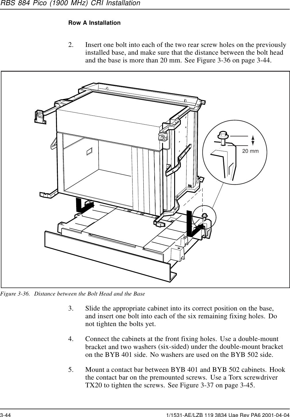
UserManual.wiki
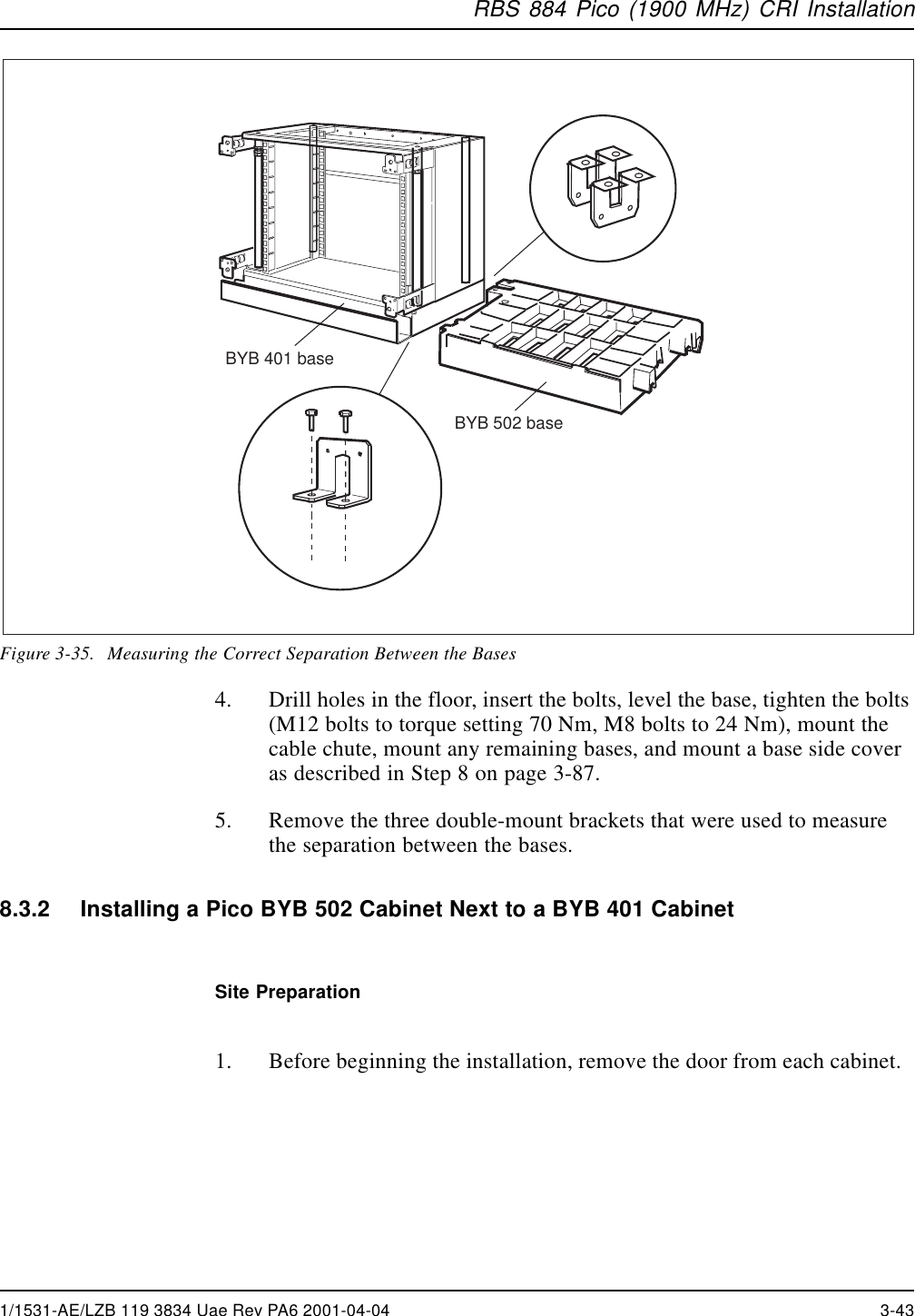
>
HARRIS
>
KRC121107 1 User Manual
exhibit 8
Navigation menu
Upload a User Manual
Namespaces
Wiki Guide
HTML
PDF
Info
Views
User Manual
Discussion / Help
Navigation

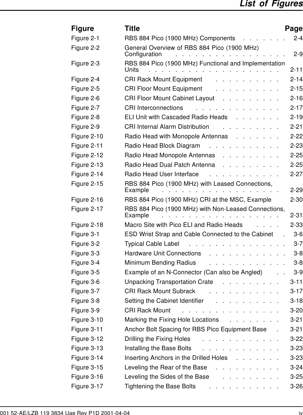
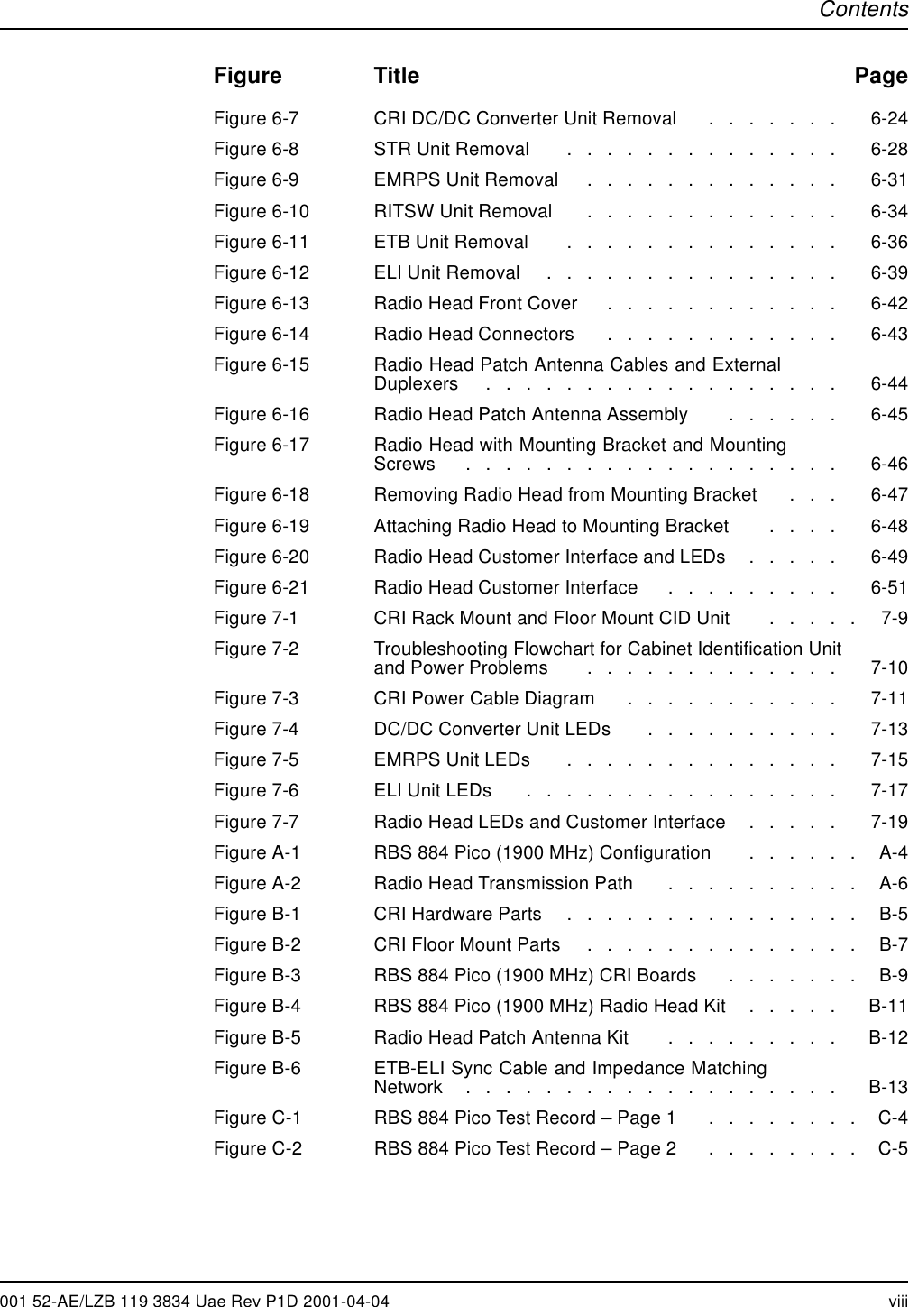

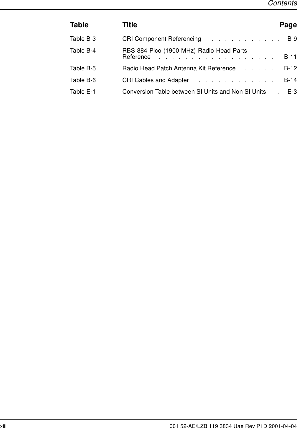
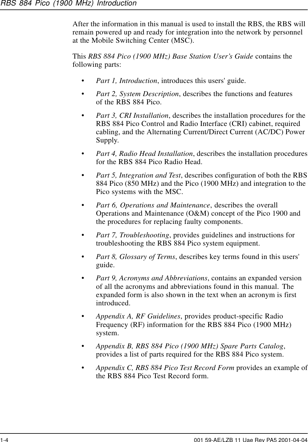


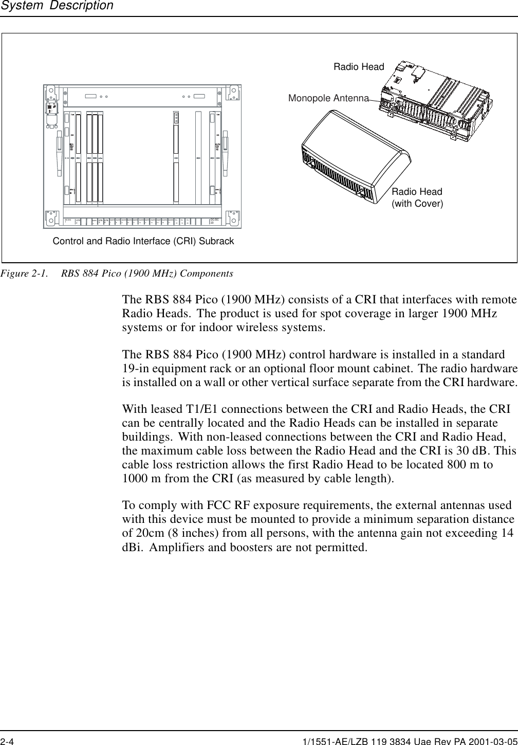
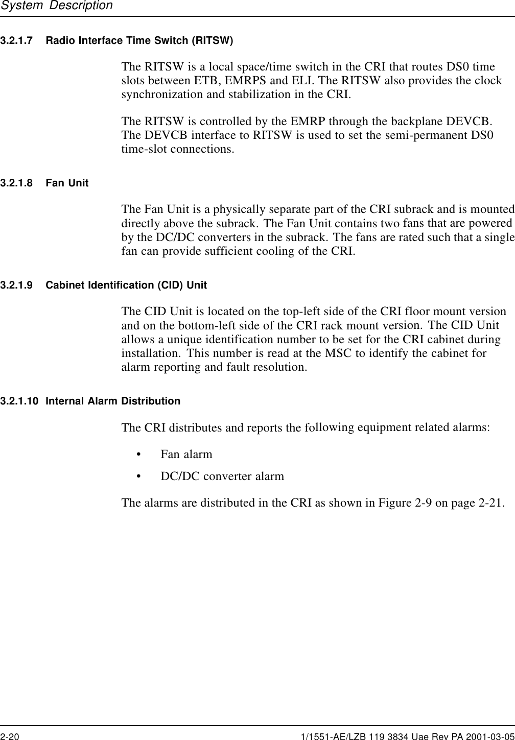
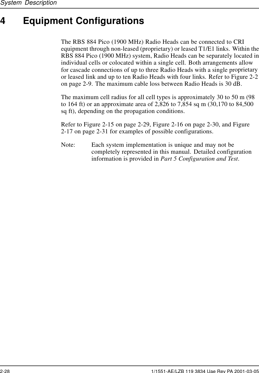

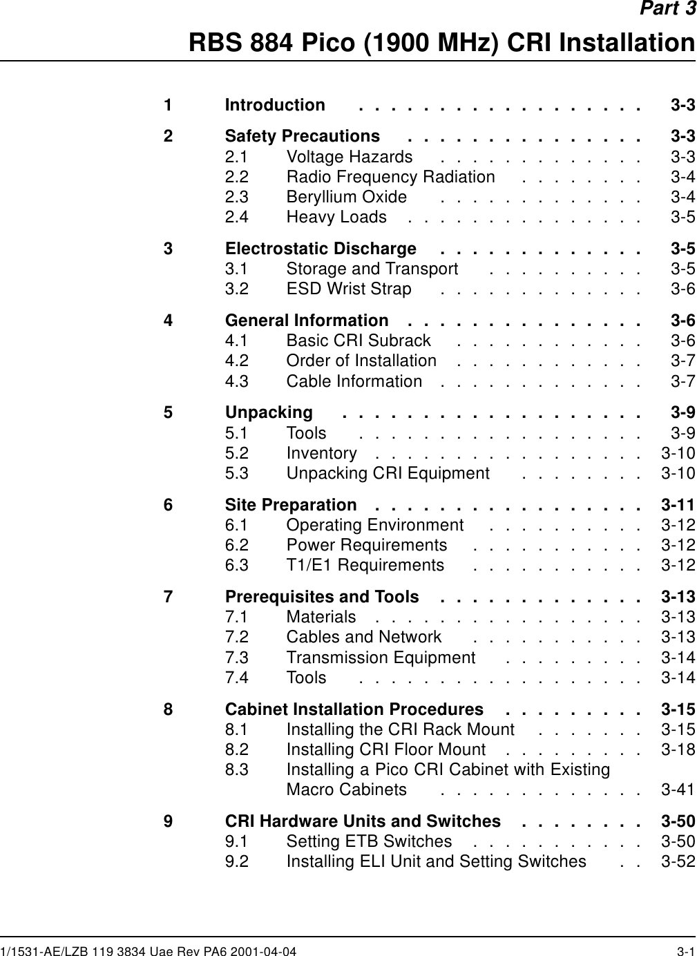
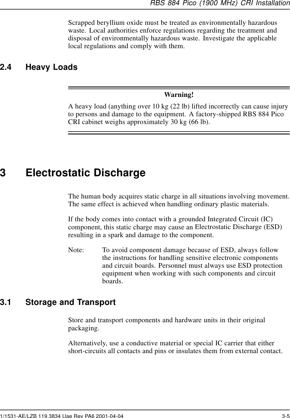
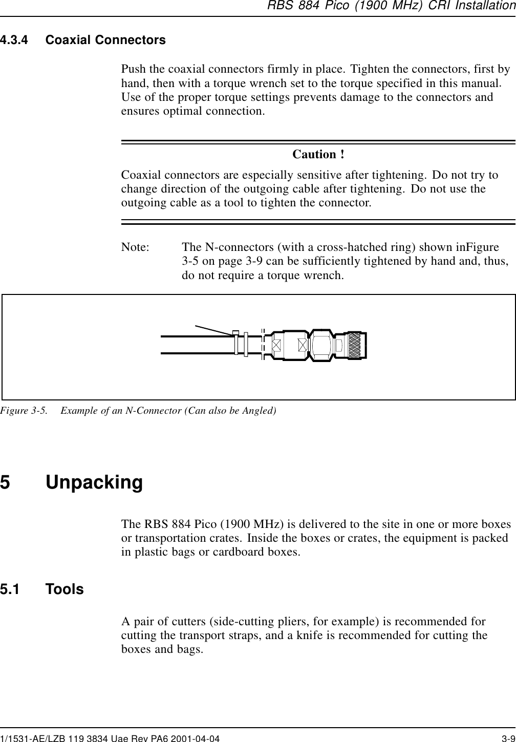
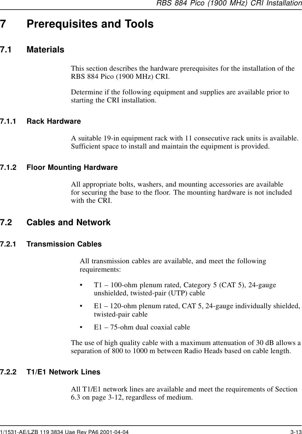
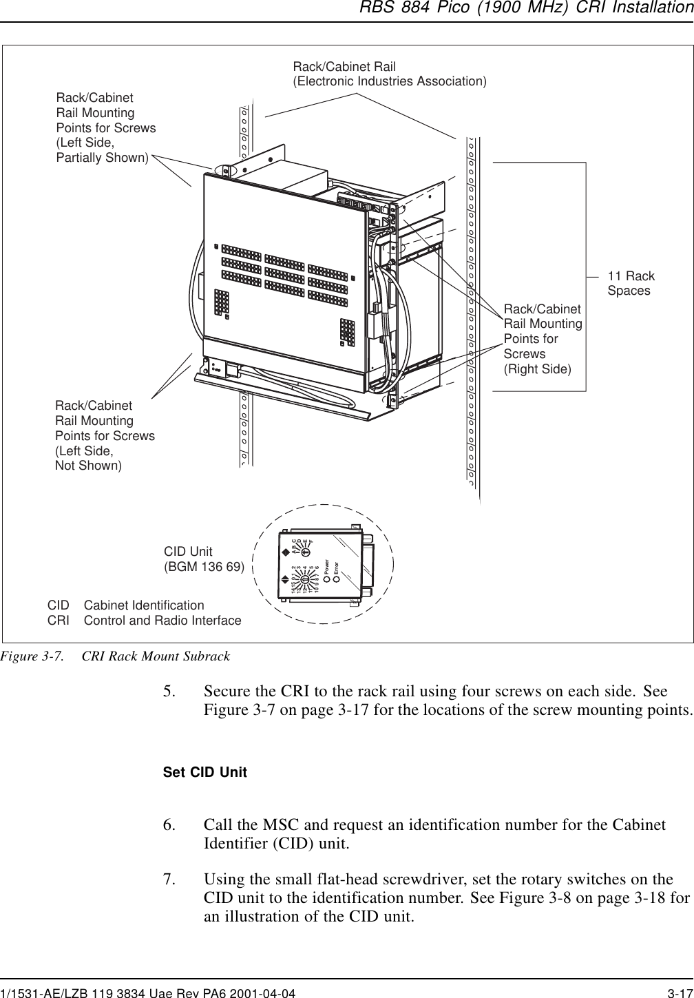
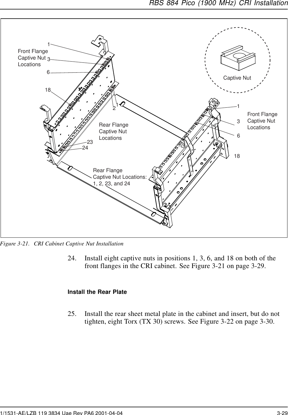
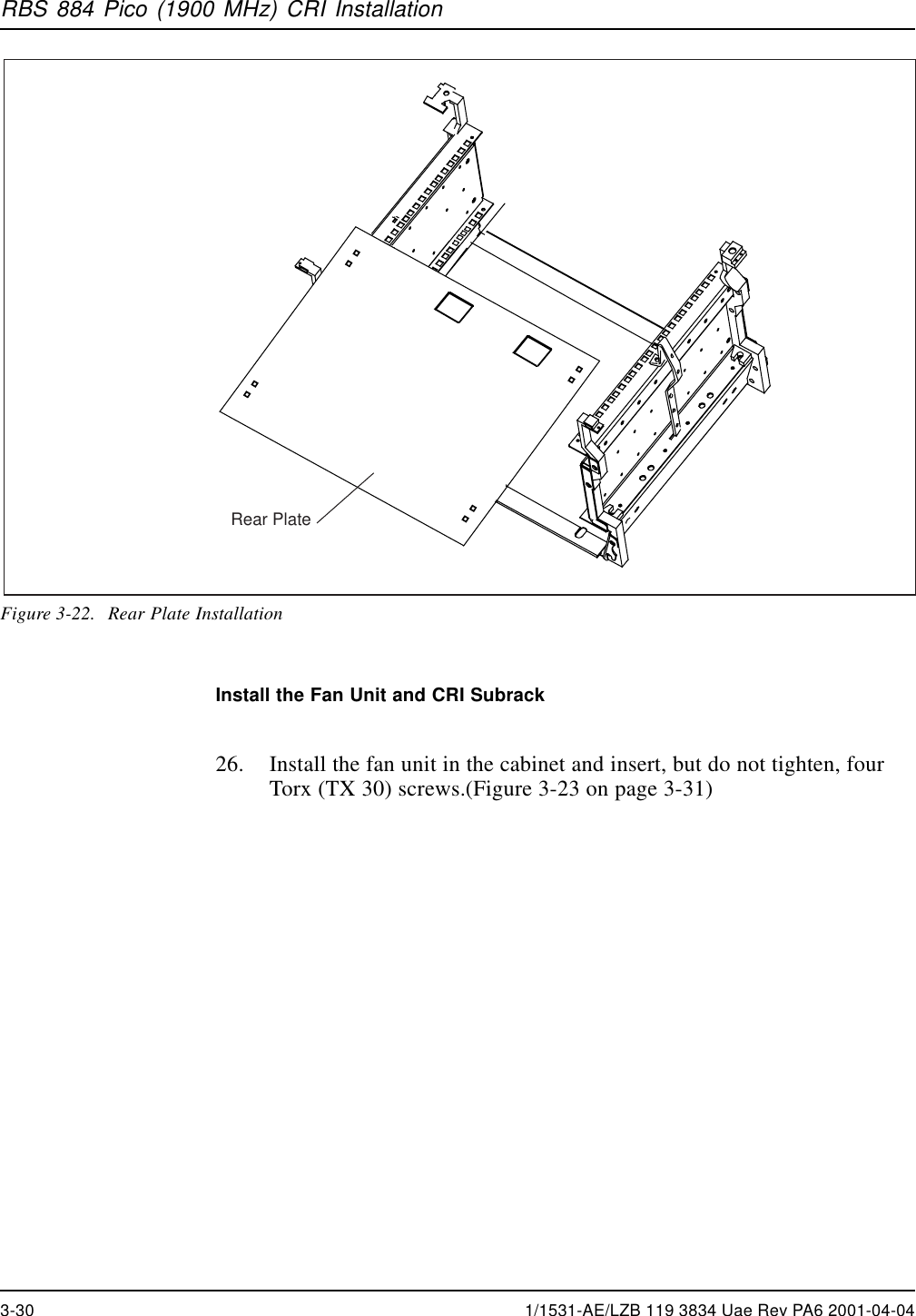
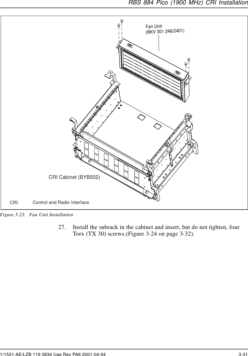
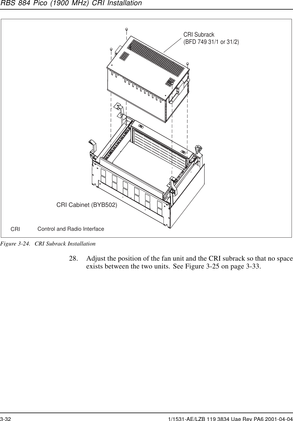
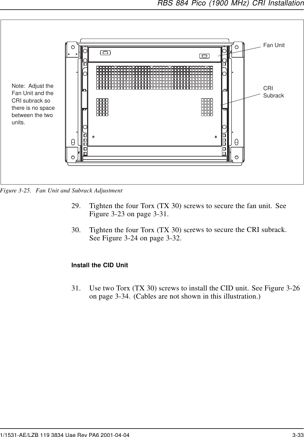
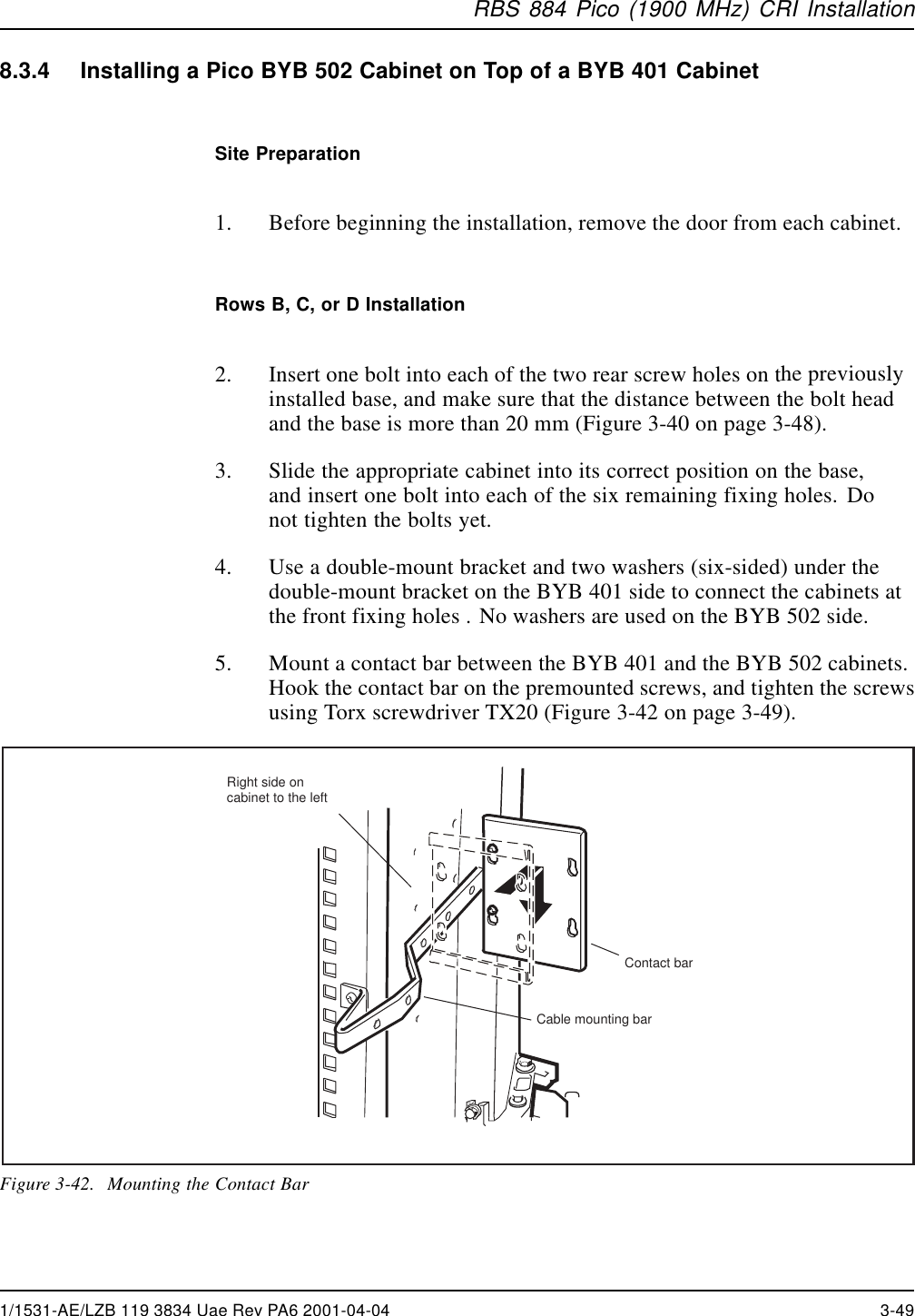
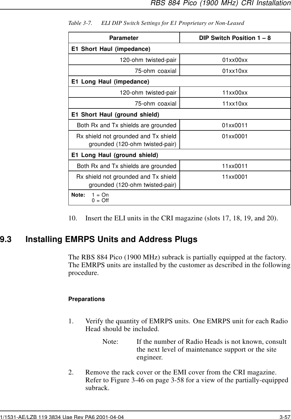
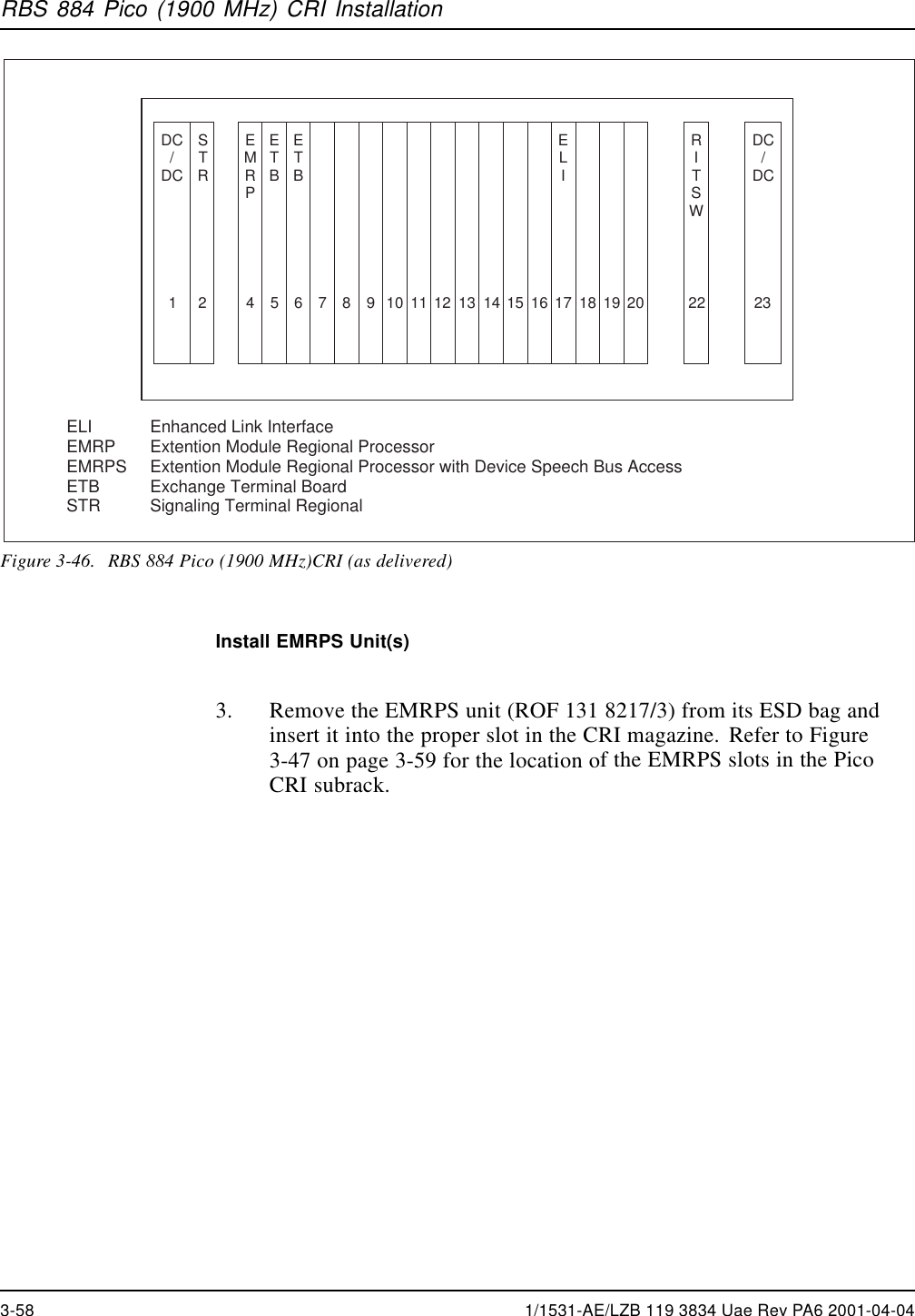
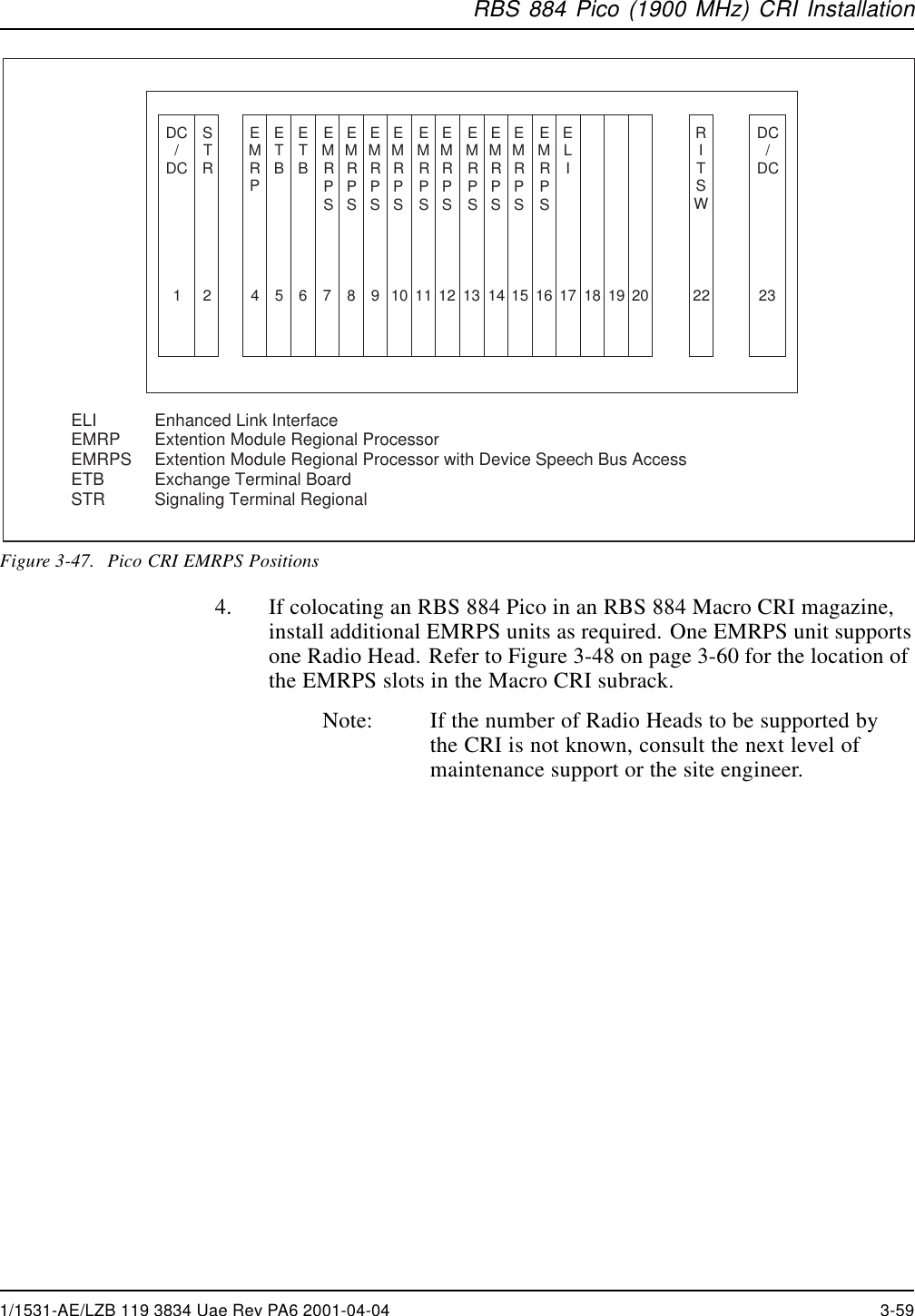
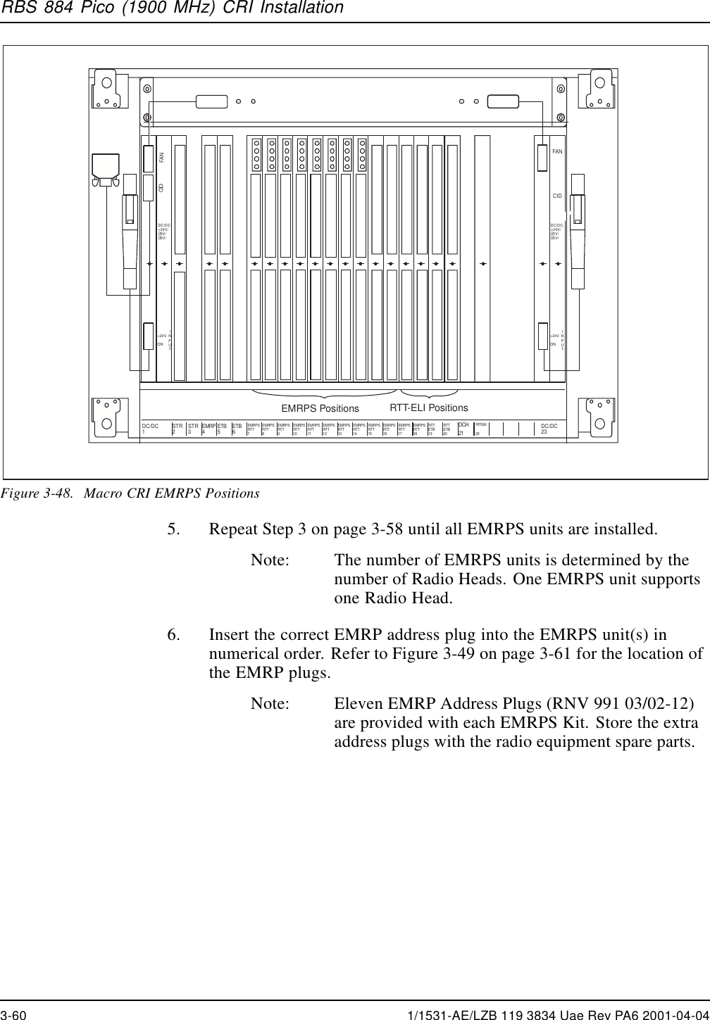
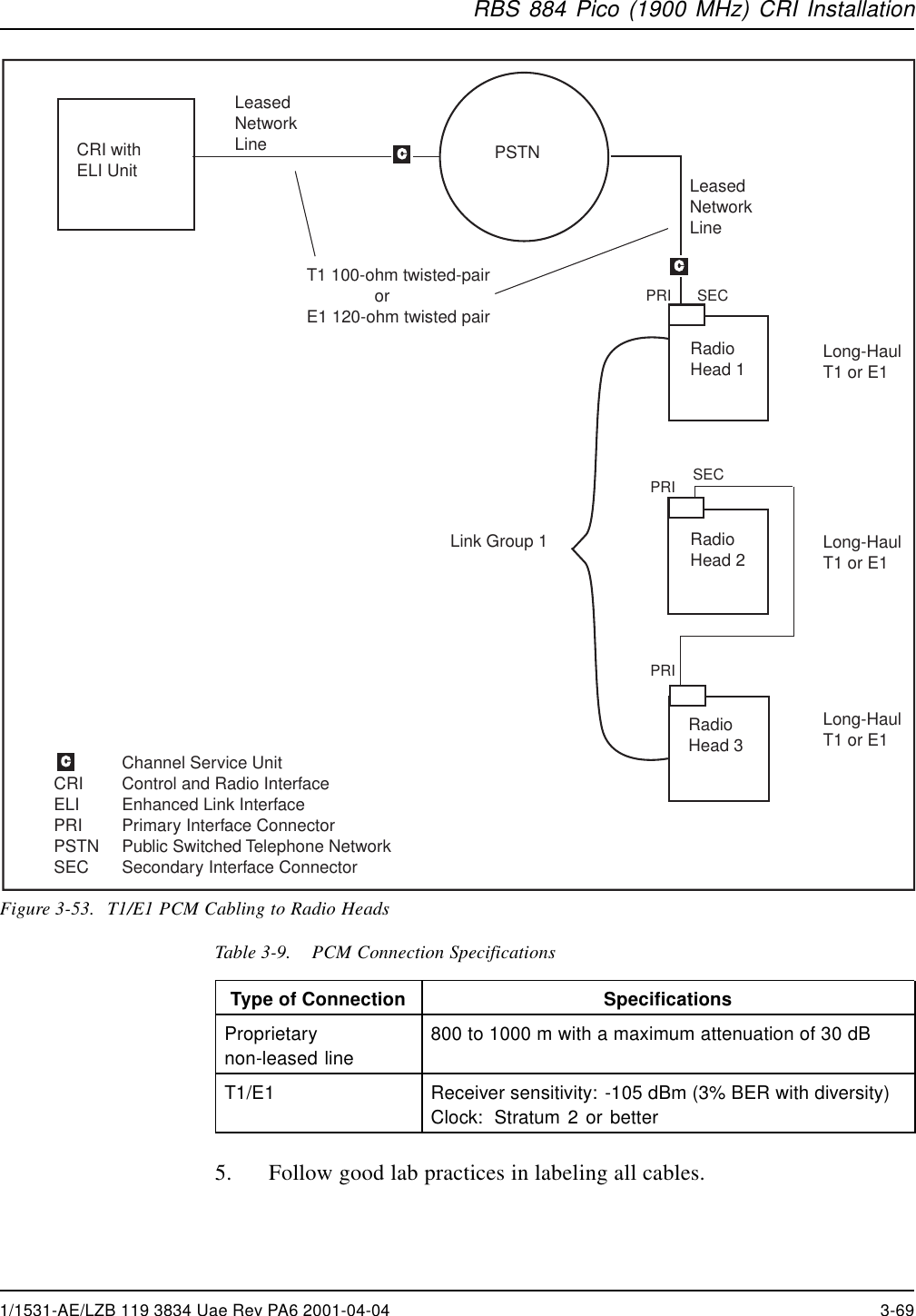
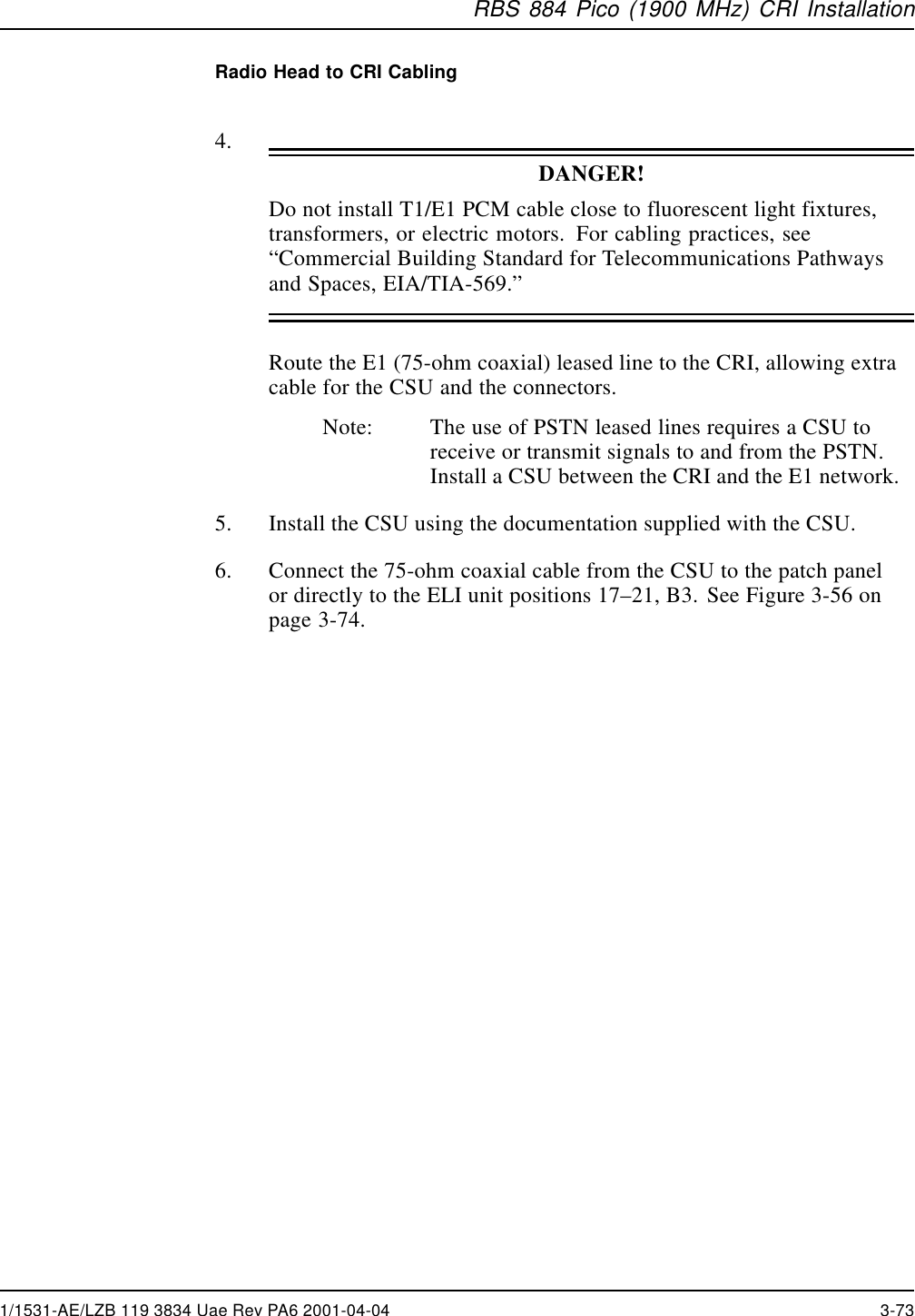
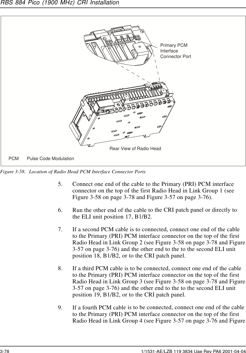
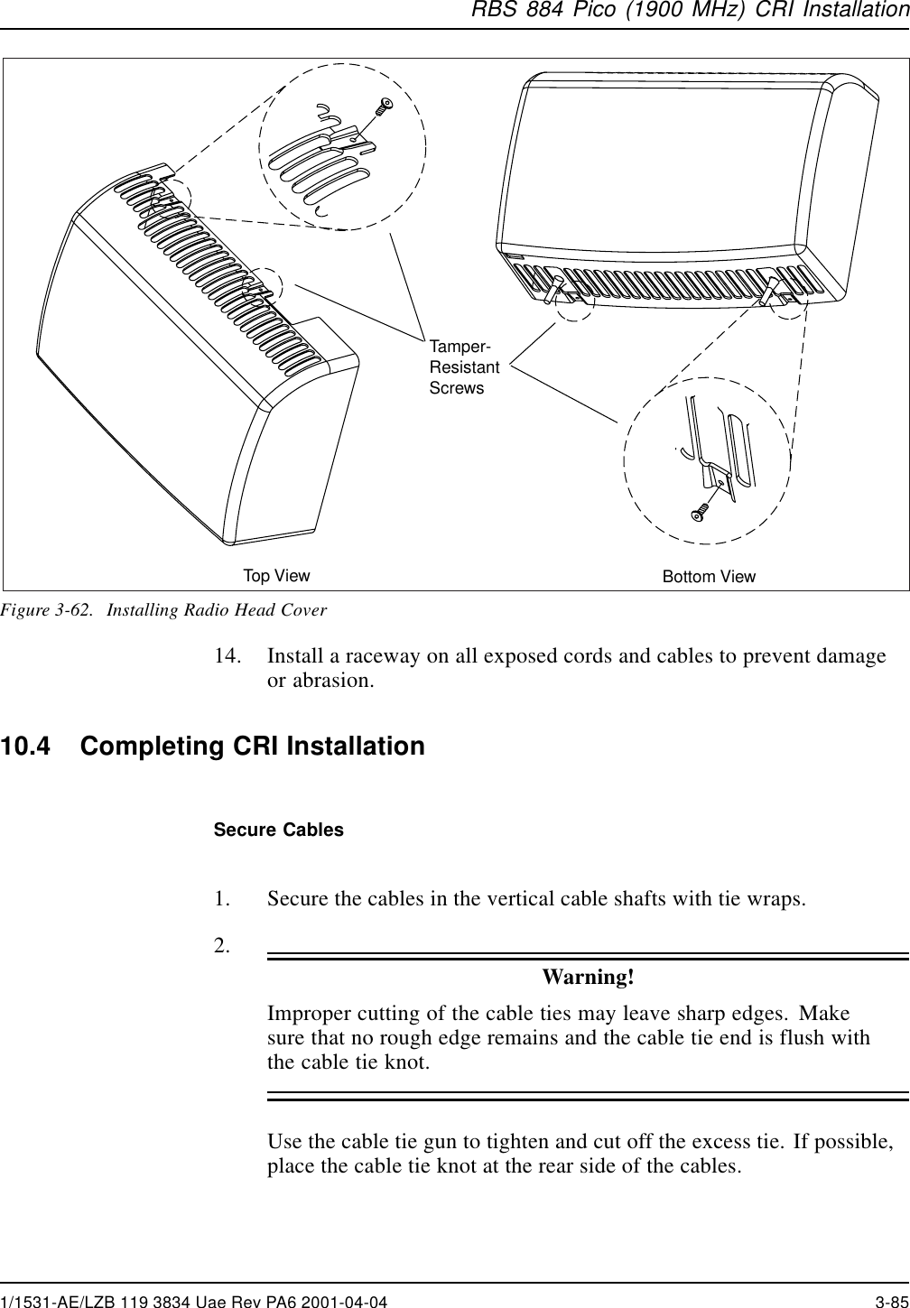
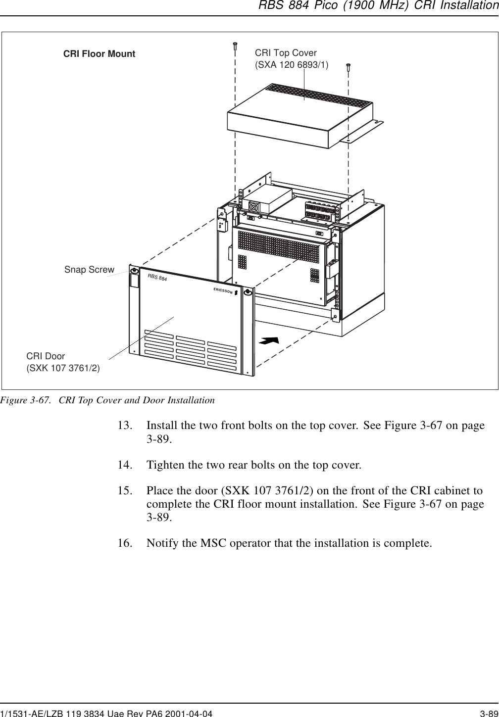
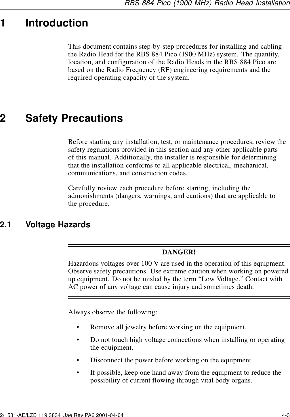
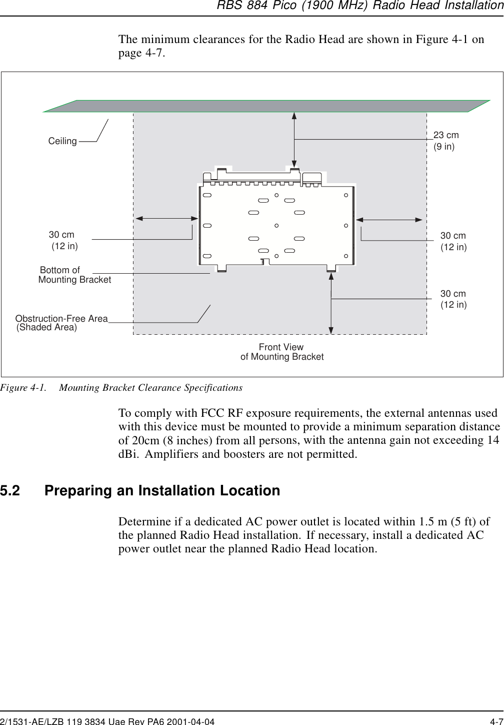
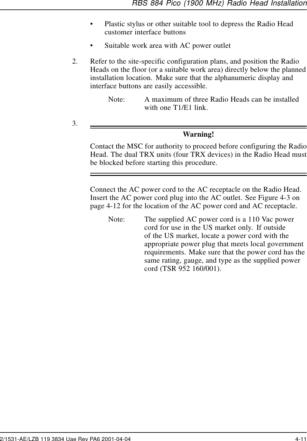
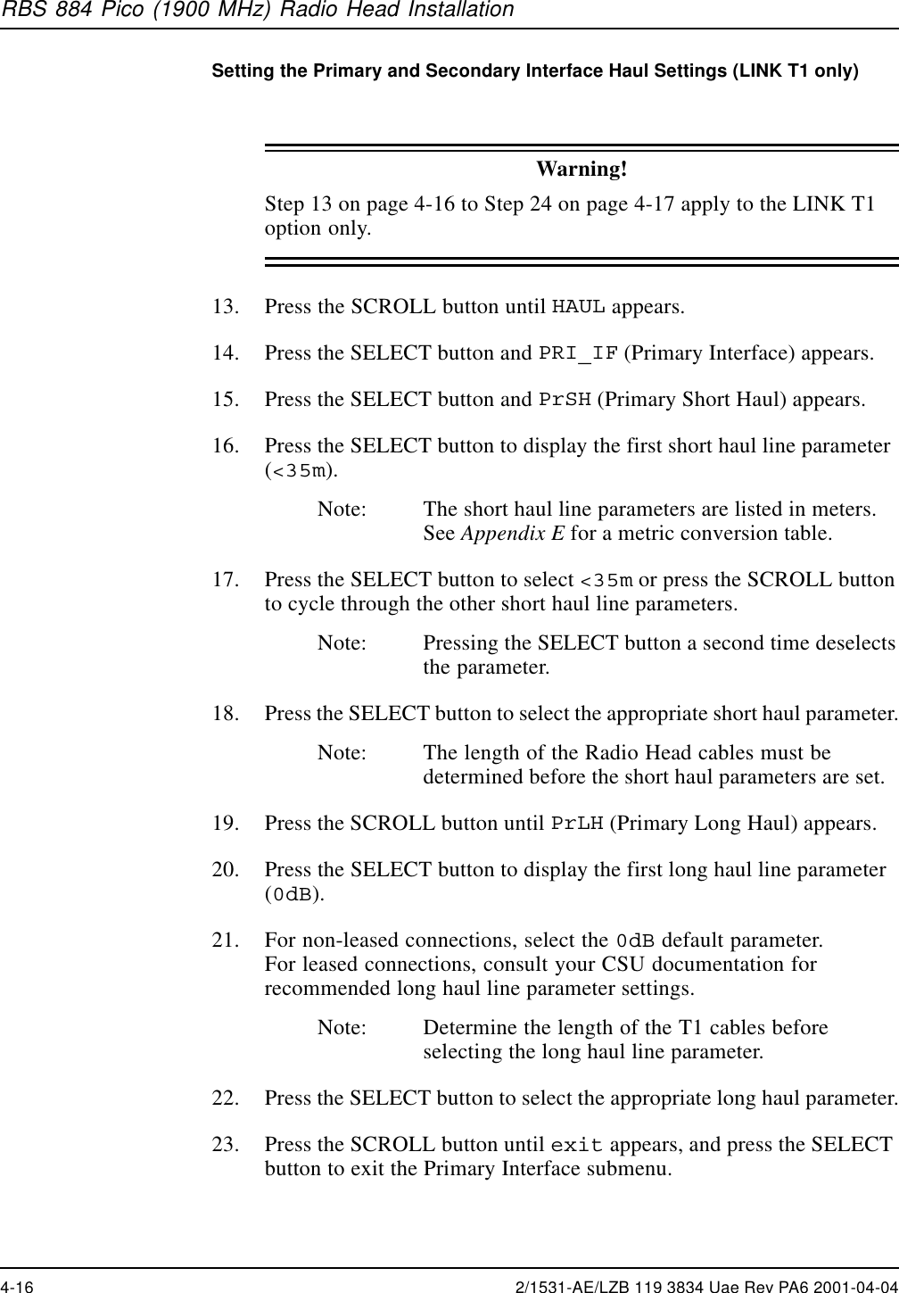
![RBS 884 Pico (1900 MHz) Radio Head Installation8. The factory default settings are as follows:•Link Type = T1•Primary Haul Type = Long Haul, 0 dB•Secondary Haul Type = Long Haul, 0 dB•Network PLL Specification = ATT•Cascade Position = ENDN (not at the end)•Cabinet ID Number = 0Setting the Link Type9. Press the SELECT button to exit the Alarm Status mode and accessthe Configuration program. The first menu item, LINK, appears onthe display.10. Press the SELECT button and T1 appears. The brackets reflect thecurrent setting.Note: The current parameters are enclosed in brackets. Anasterisk, *, appears next to parameters that have beenselected, but not enabled.11. Press the SELECT button to select the T1 parameter or press theSCROLL button followed by the SELECT button to select the E1parameter.Note: Pressing the SELECT button a second time deselectsthe parameter.12. Press the SCROLL button followed by the SELECT button to exit theLink Type option.Table 4-2. Configuration Program –Link MenuMenu Parameters Explanation Notes[T1] 1.544 Mbpstransmission linkSpecifies T1 link.LINKE1 2.048 Mbpstransmission linkSpecifies E1 link.2/1531-AE/LZB 119 3834 Uae Rev PA6 2001-04-04 4-15](https://usermanual.wiki/HARRIS/KRC121107-1/User-Guide-143185-Page-165.png)
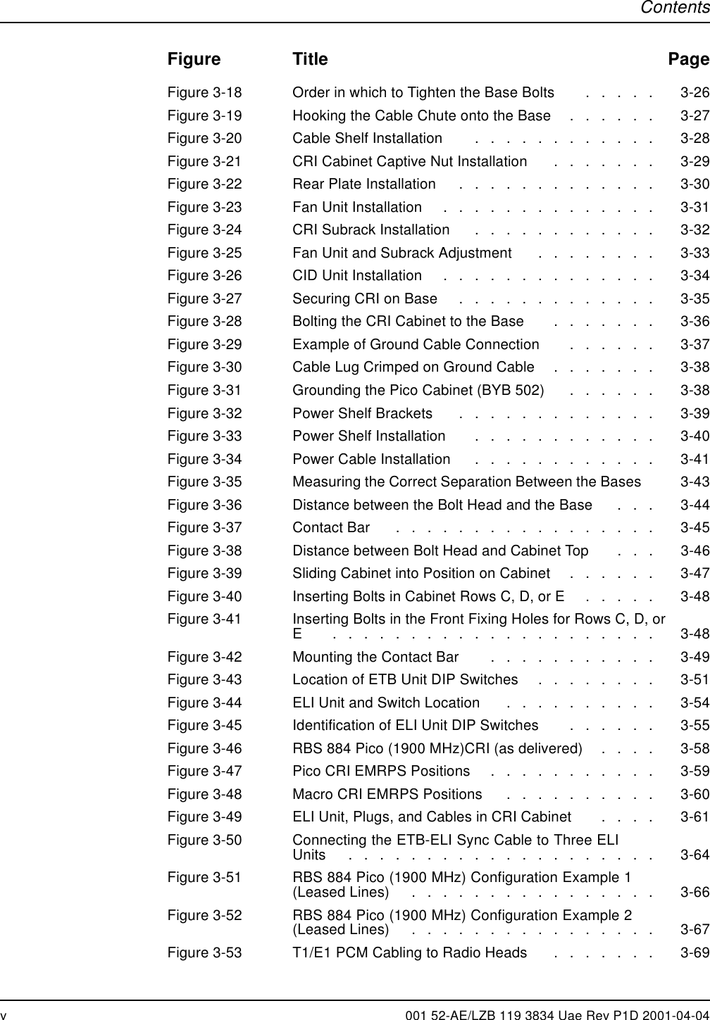
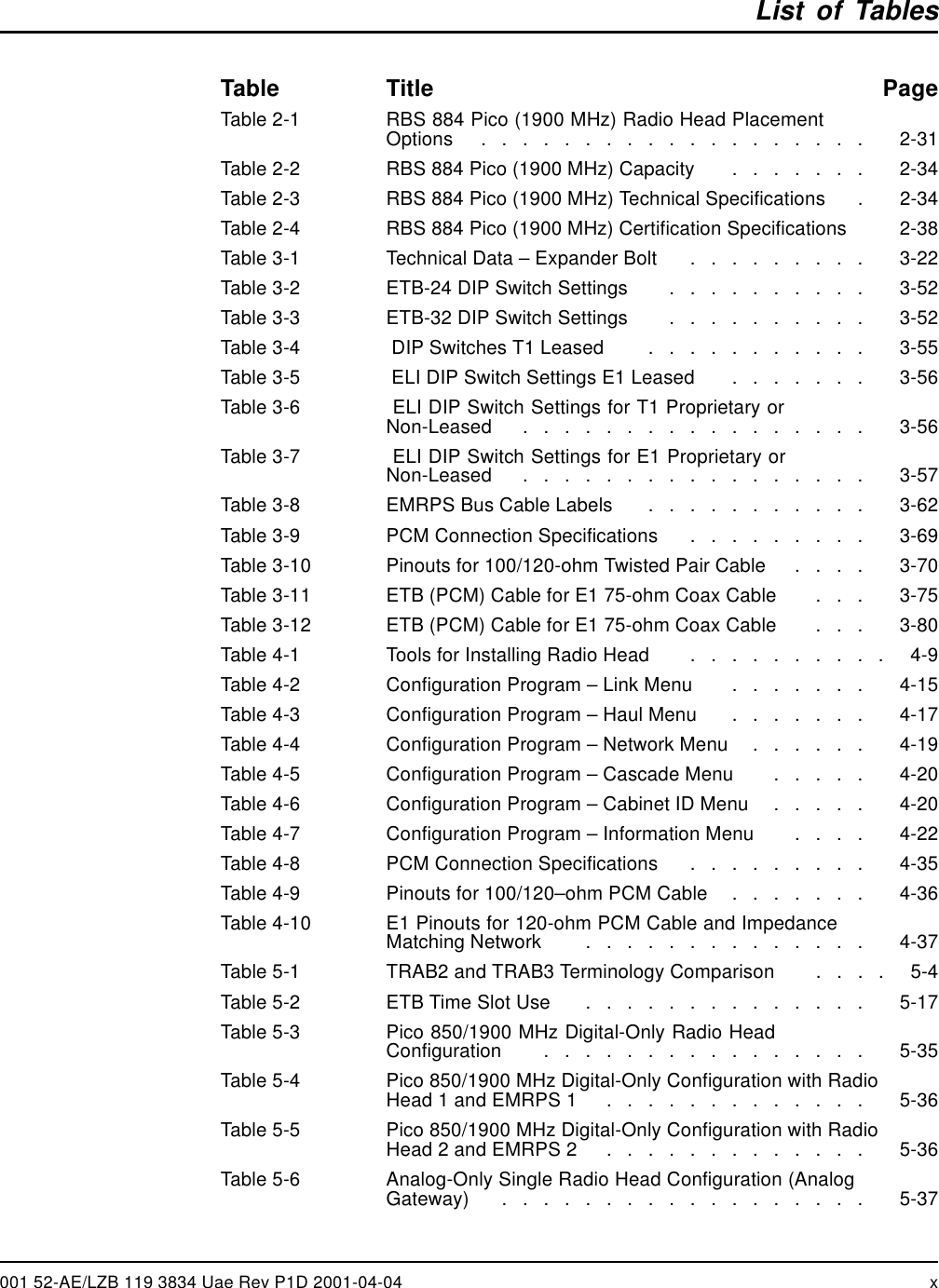
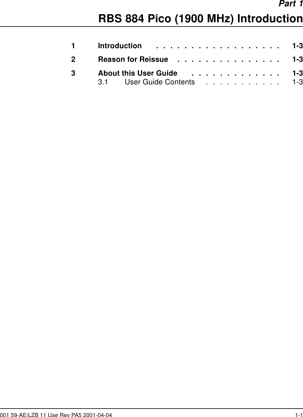
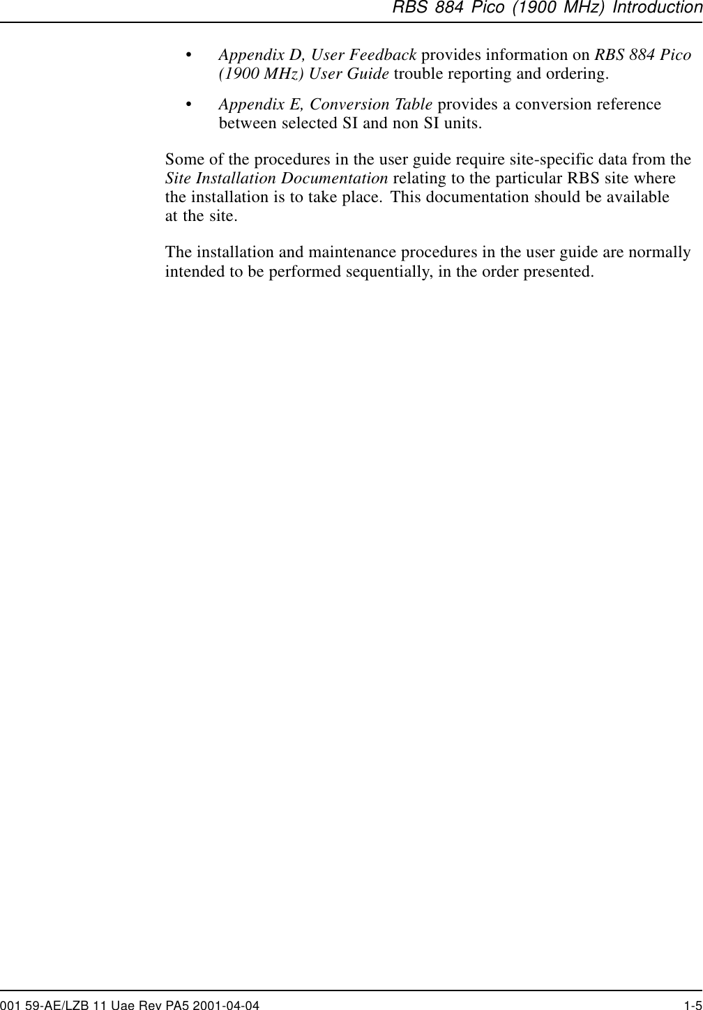
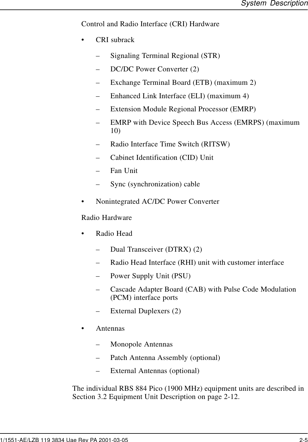
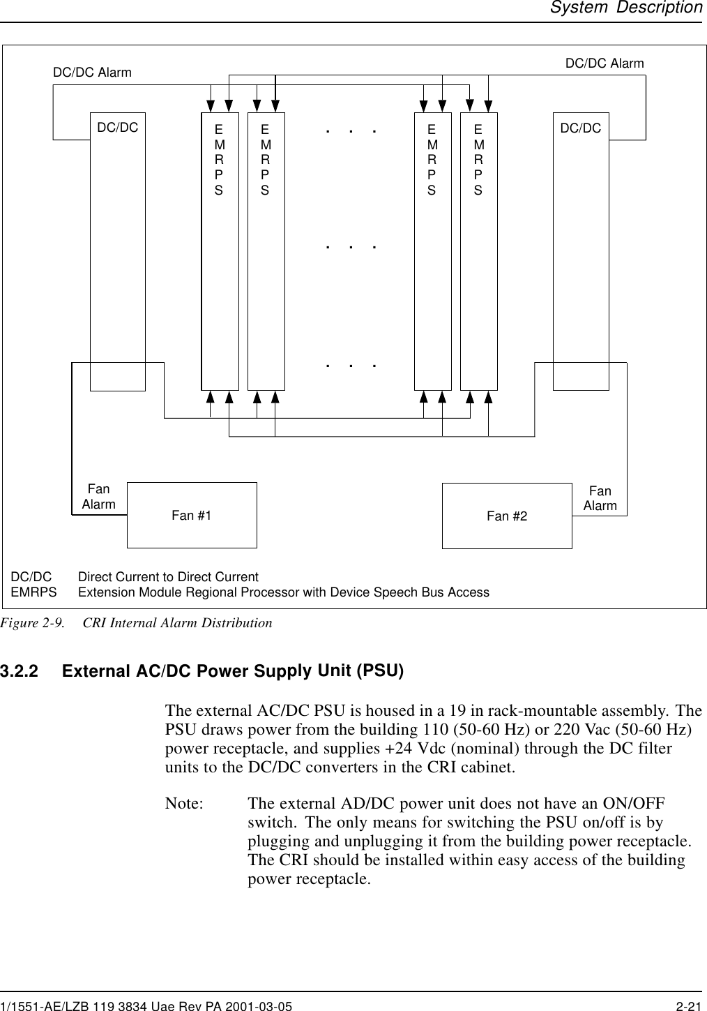
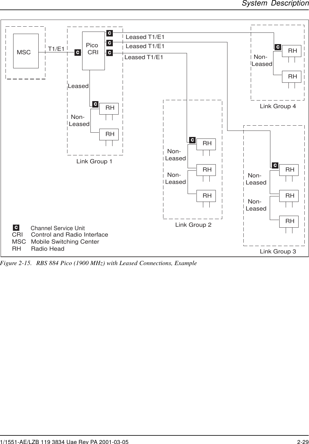
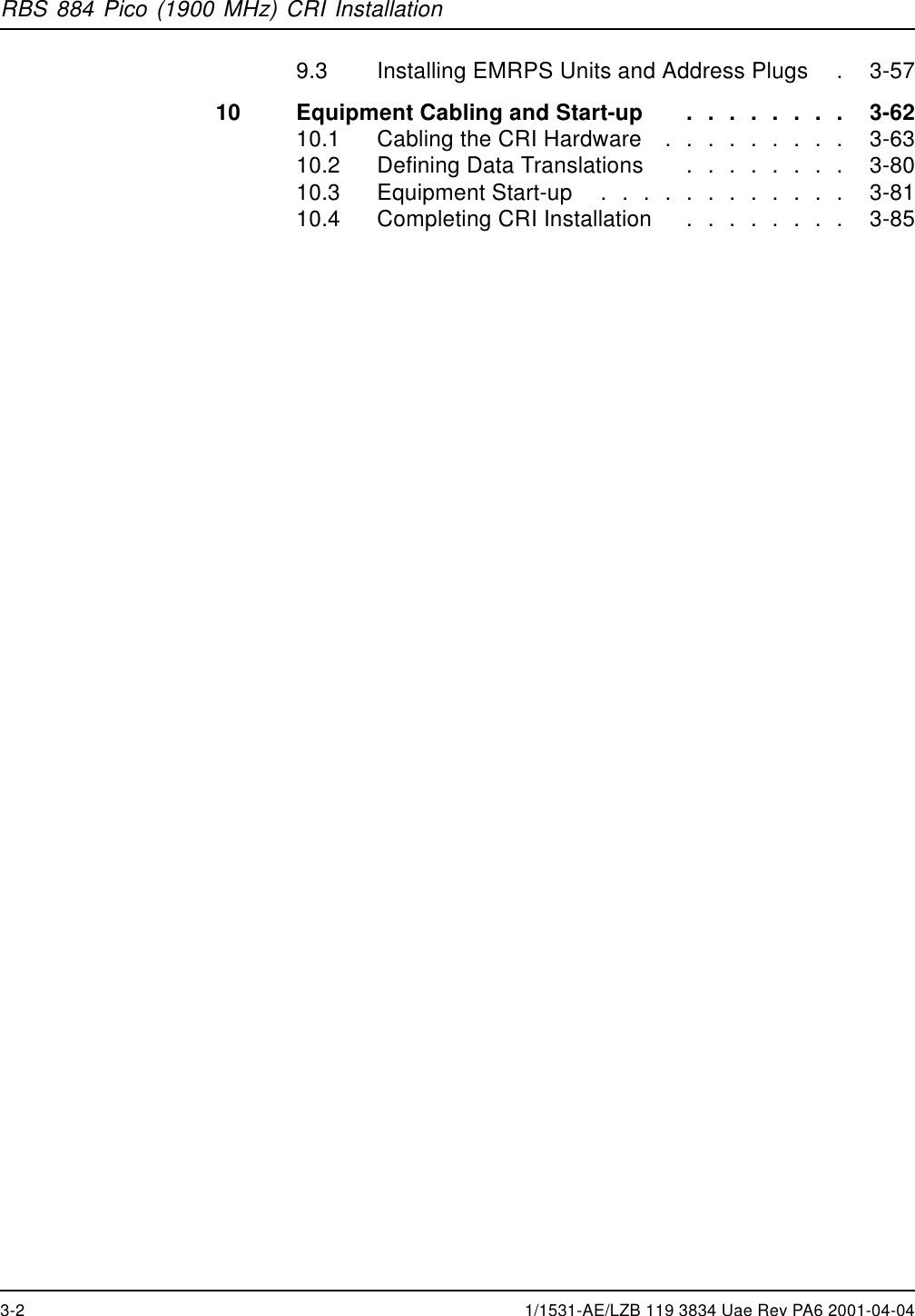
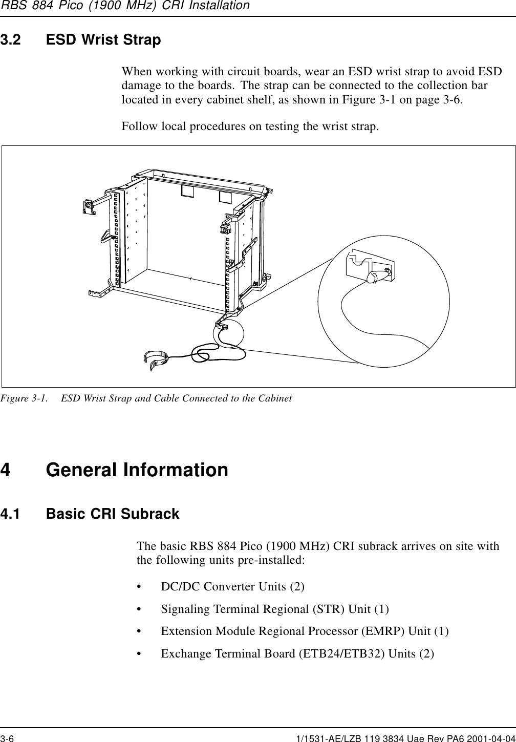
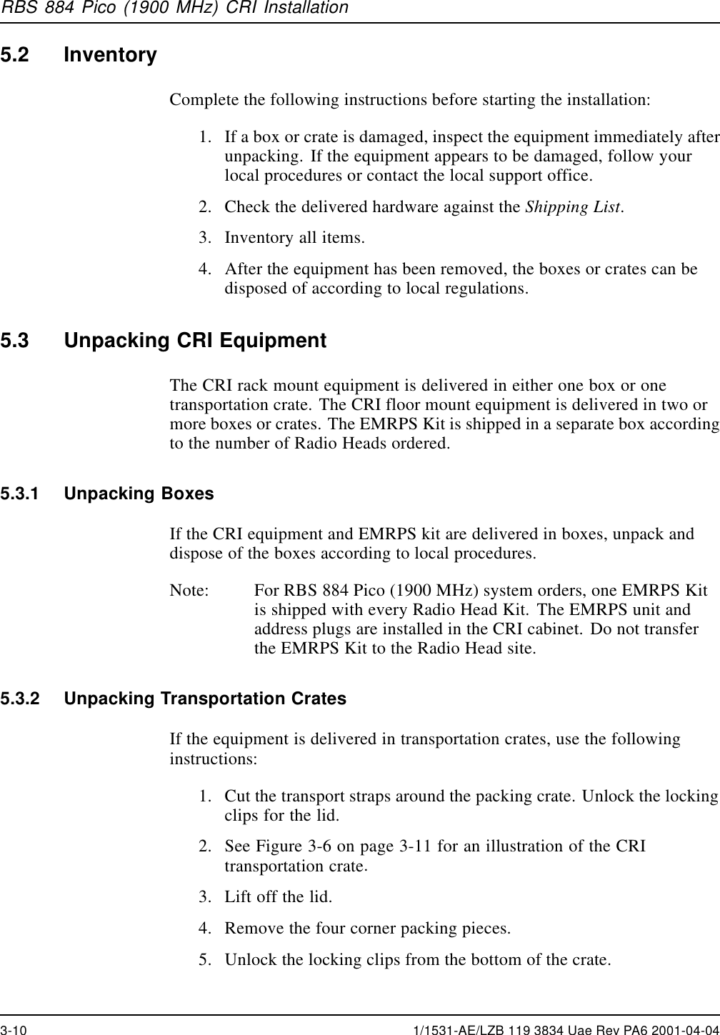
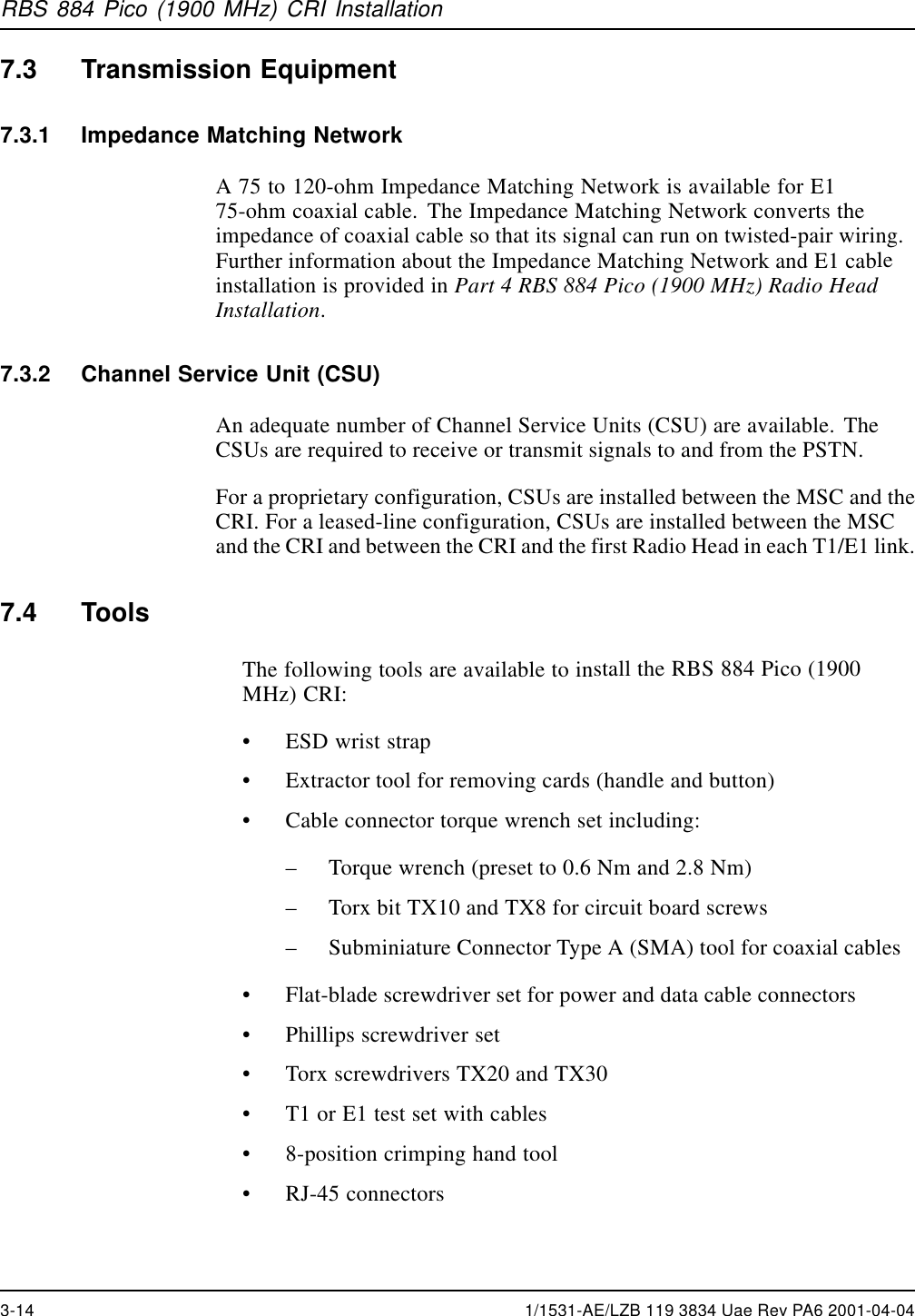
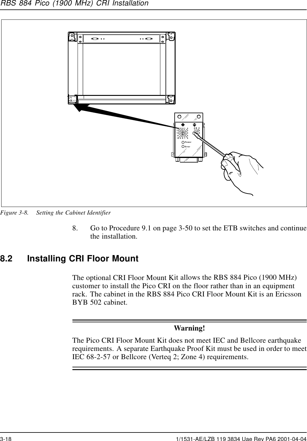
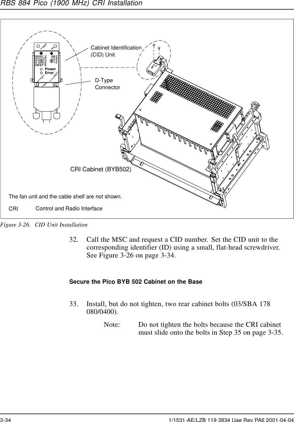
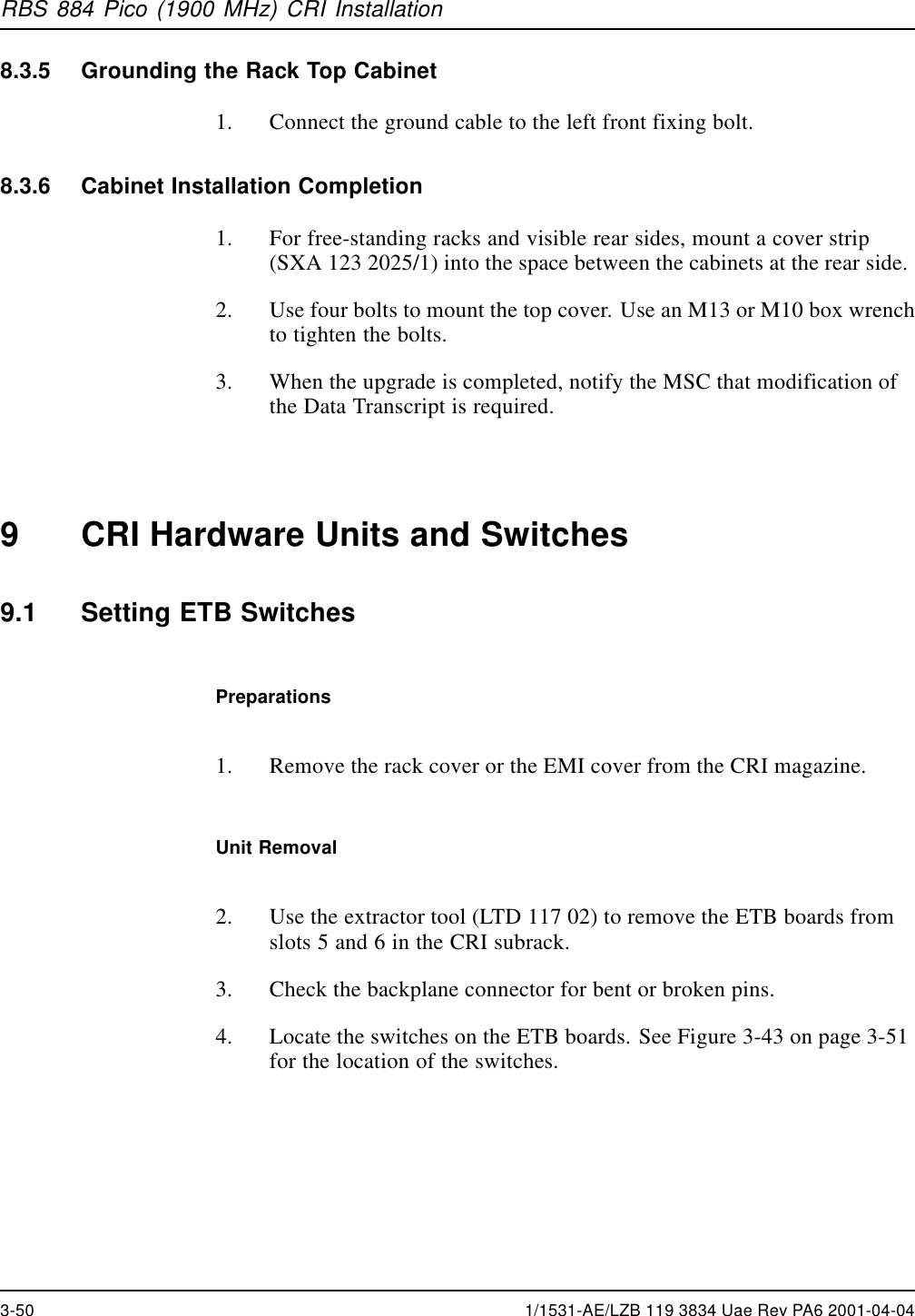
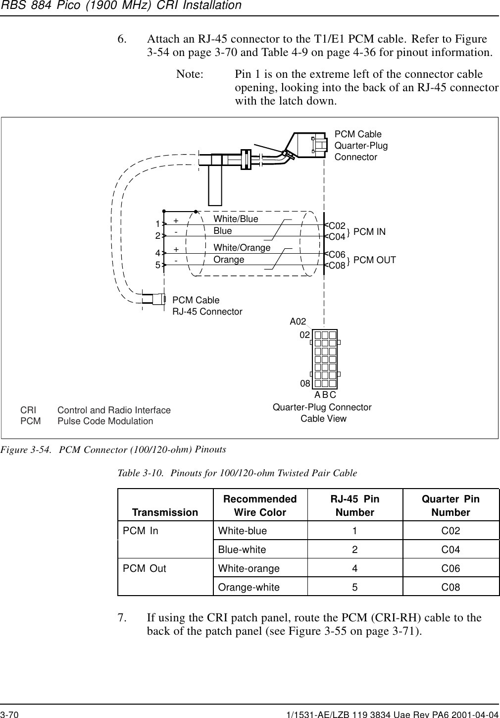
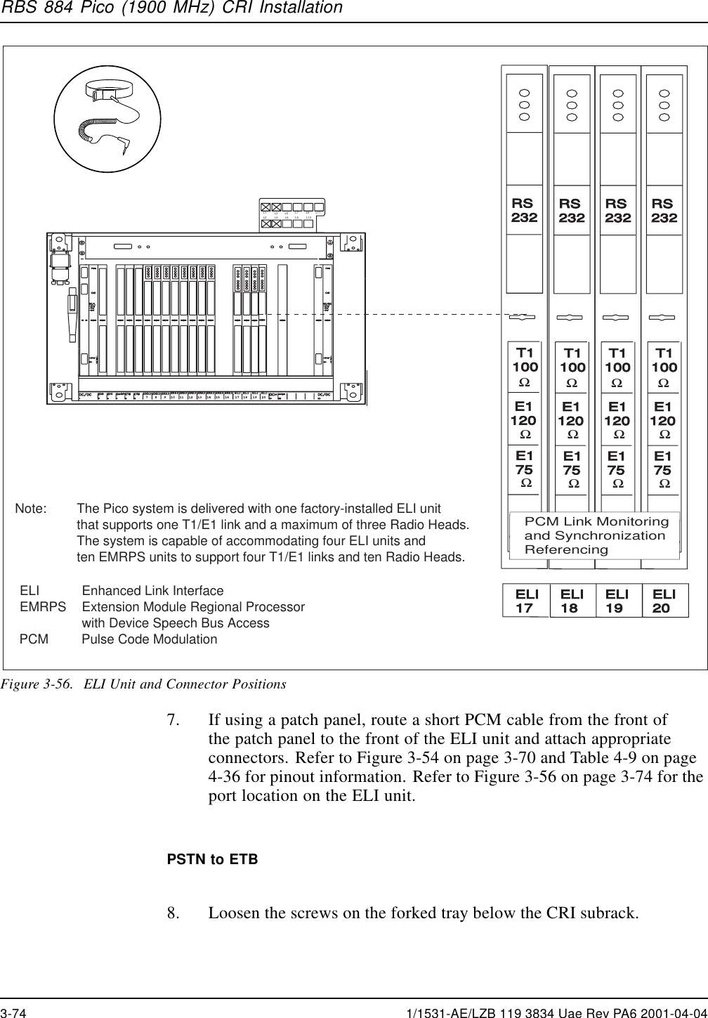
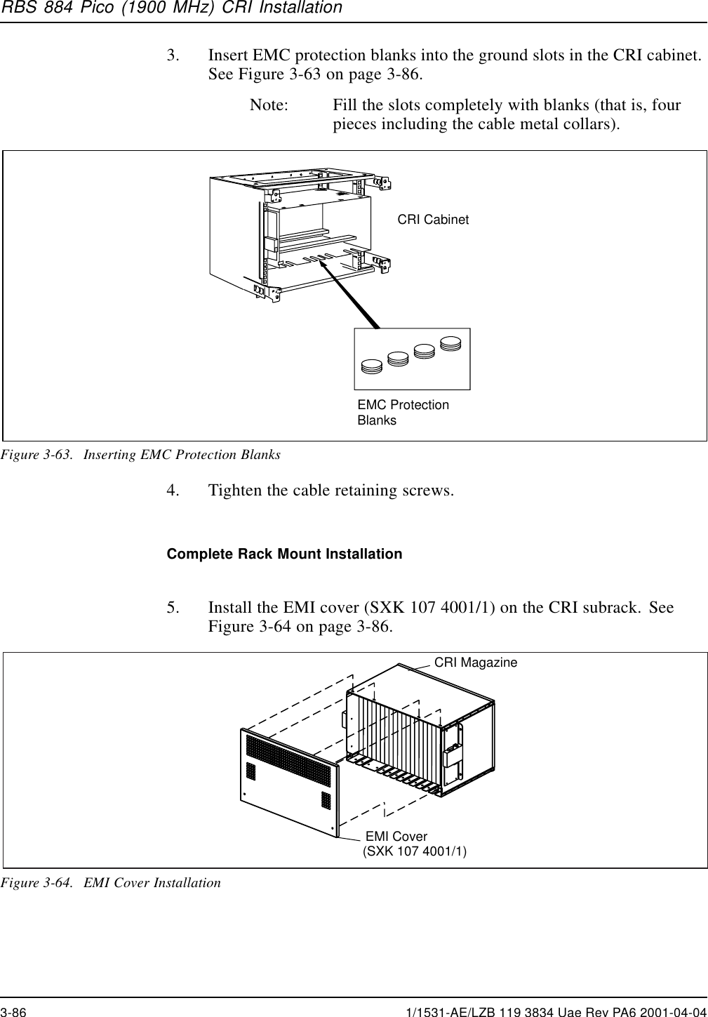
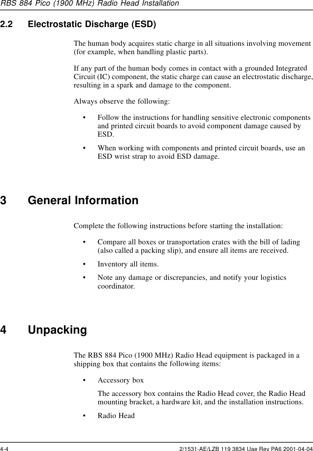
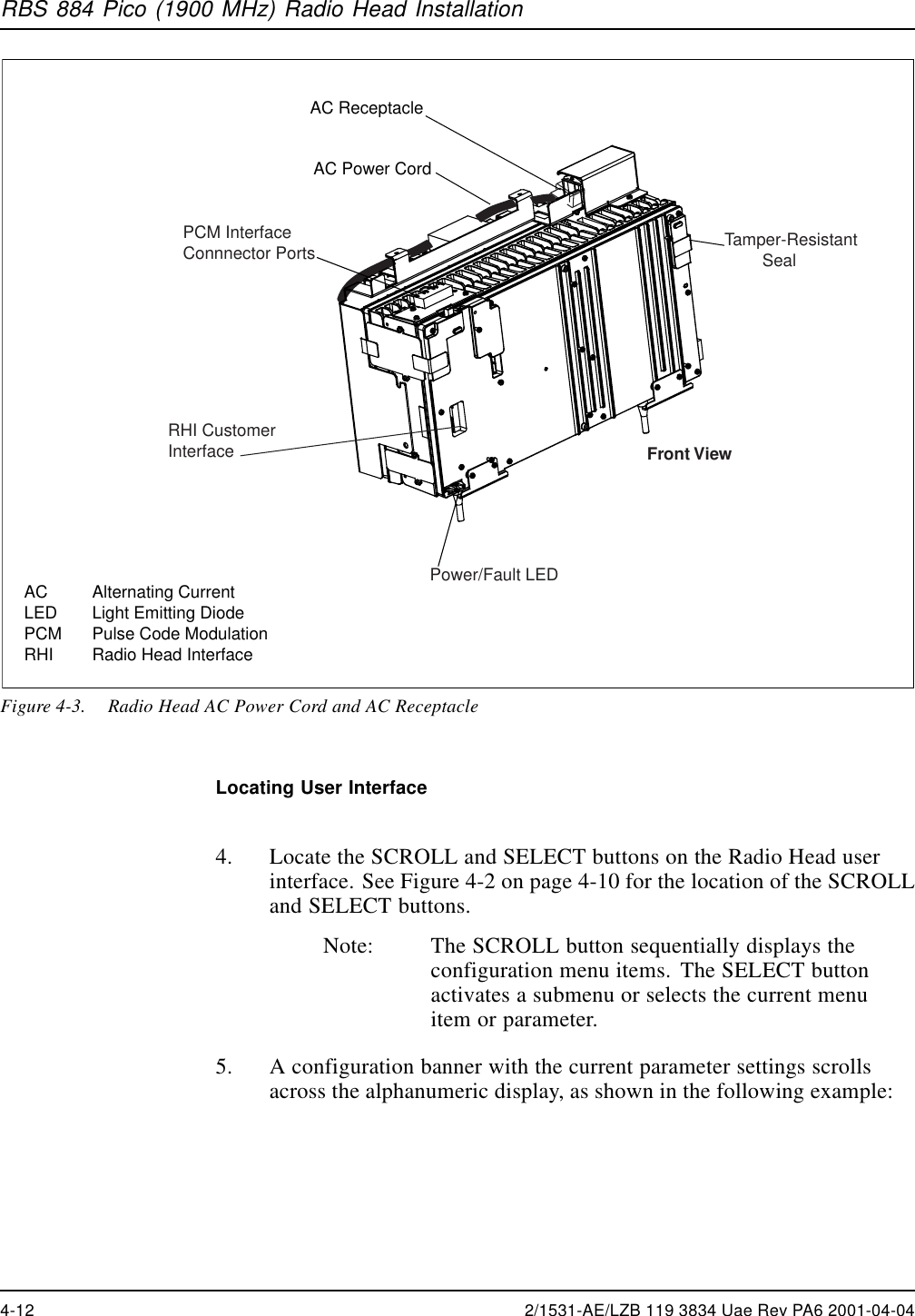
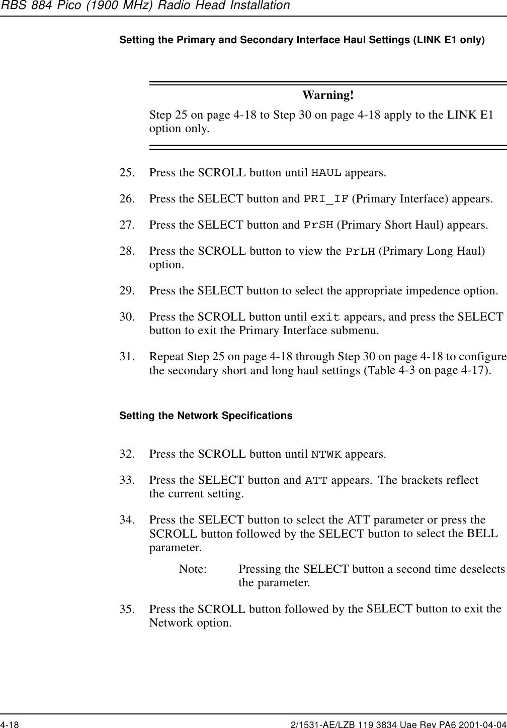
![RBS 884 Pico (1900 MHz) Radio Head Installation24. Repeat Step 14 on page 4-16 through Step 23 on page 4-16 to configurethe secondary short and long haul settings.Table 4-3. Configuration Program –Haul MenuMenu Submenu Submenu Parameters ExplanationPrSH <35m<65m<95m<125<155[<185]<210Length of theconnection fromthe CRI or theprevious RadioHeadPRI_IFPrLH [0dB]-7dB-15d-22dAllowable gain1SeSH <35m<65m<95m<125<155<185<210Length of theconnection to thenext Radio HeadHAULLinkT1SEC_IFSeLH [0dB]-7dB-15d-22dAllowable gain1HAULLinkE1PRI_IF PrSHPrLHNone ImpedenceSEC_IF SeSHSeLHNone Impedence1Set at 0 dB for optimal performance.2/1531-AE/LZB 119 3834 Uae Rev PA6 2001-04-04 4-17](https://usermanual.wiki/HARRIS/KRC121107-1/User-Guide-143185-Page-167.png)
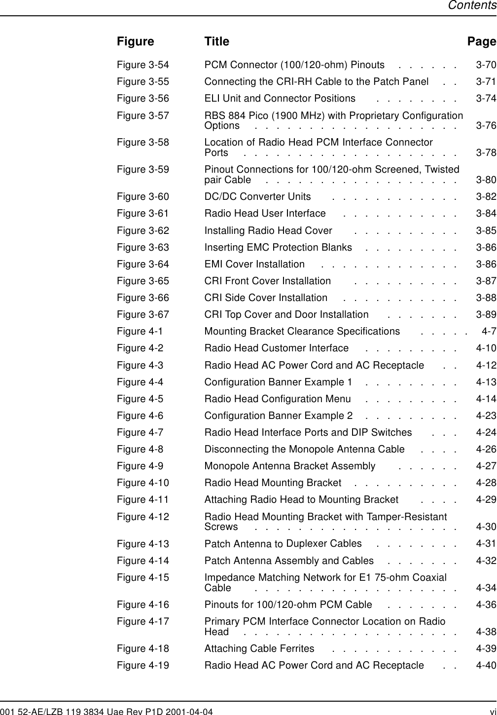
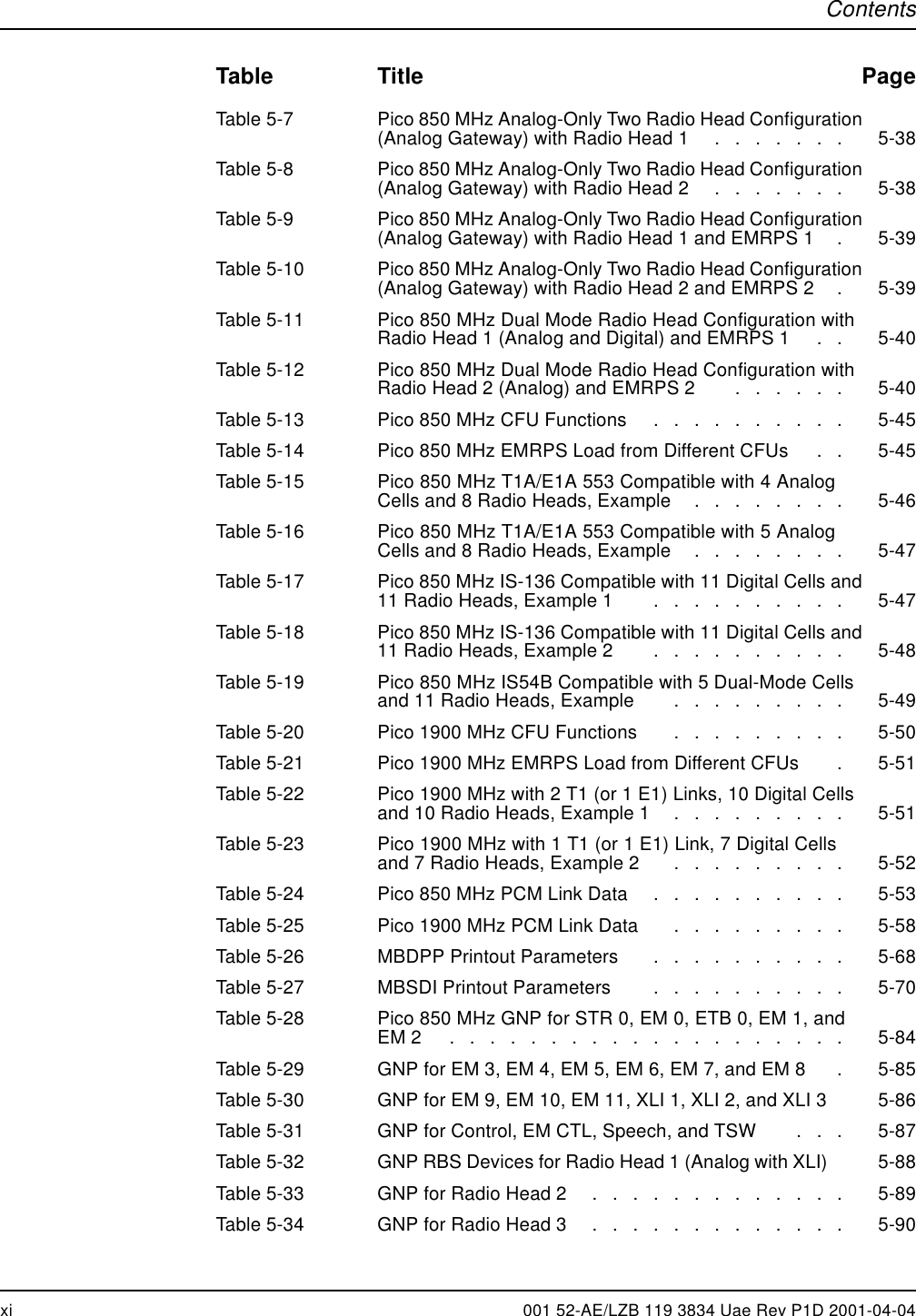
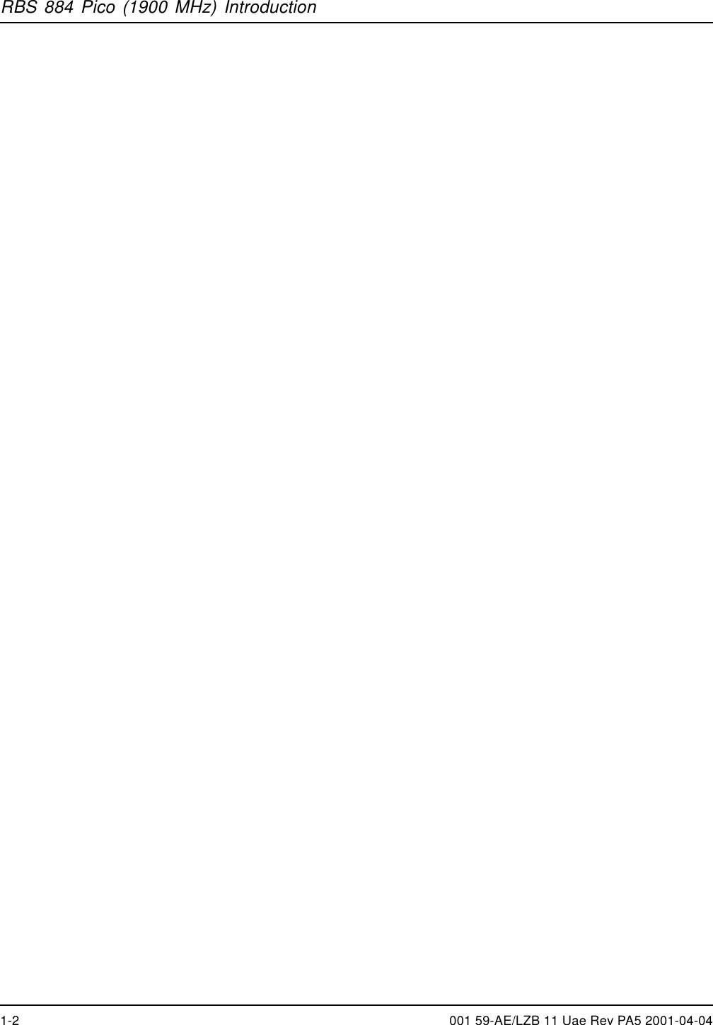
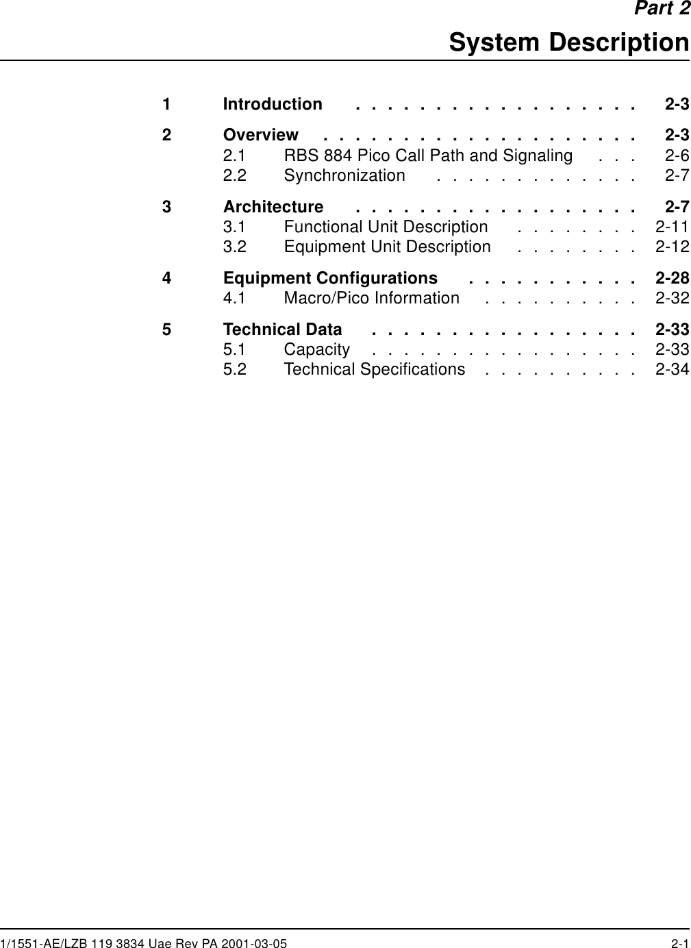
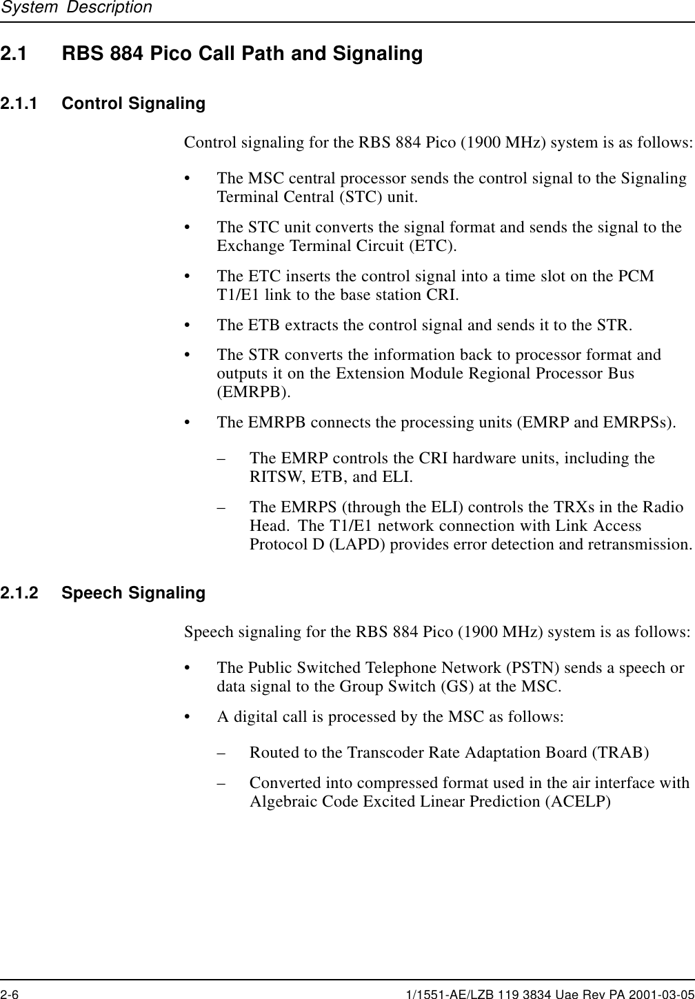
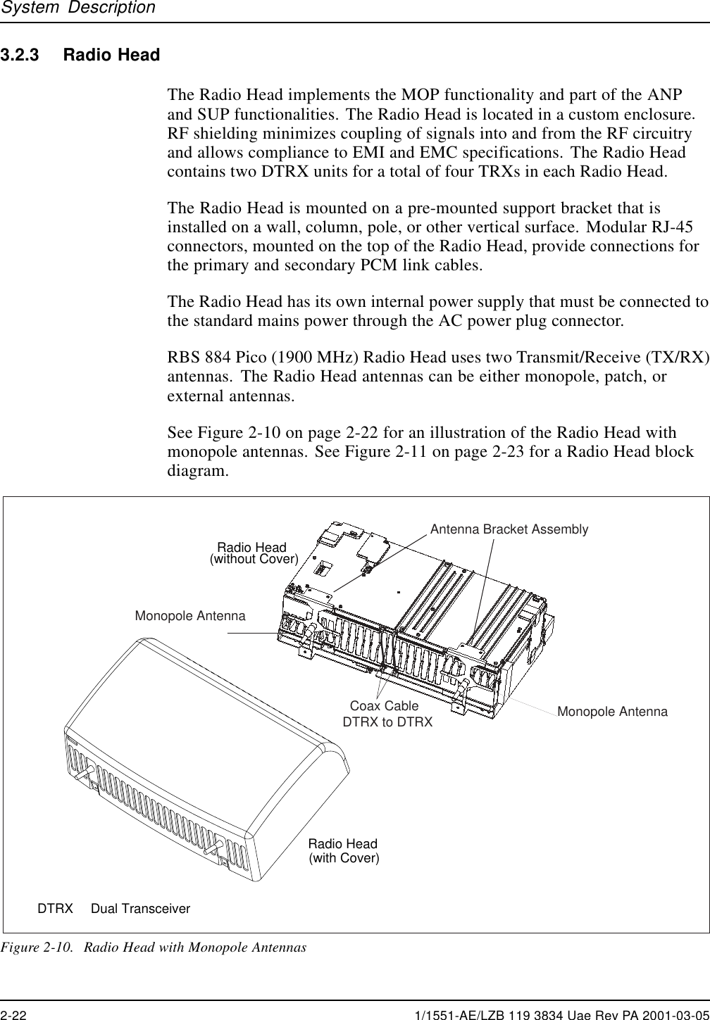
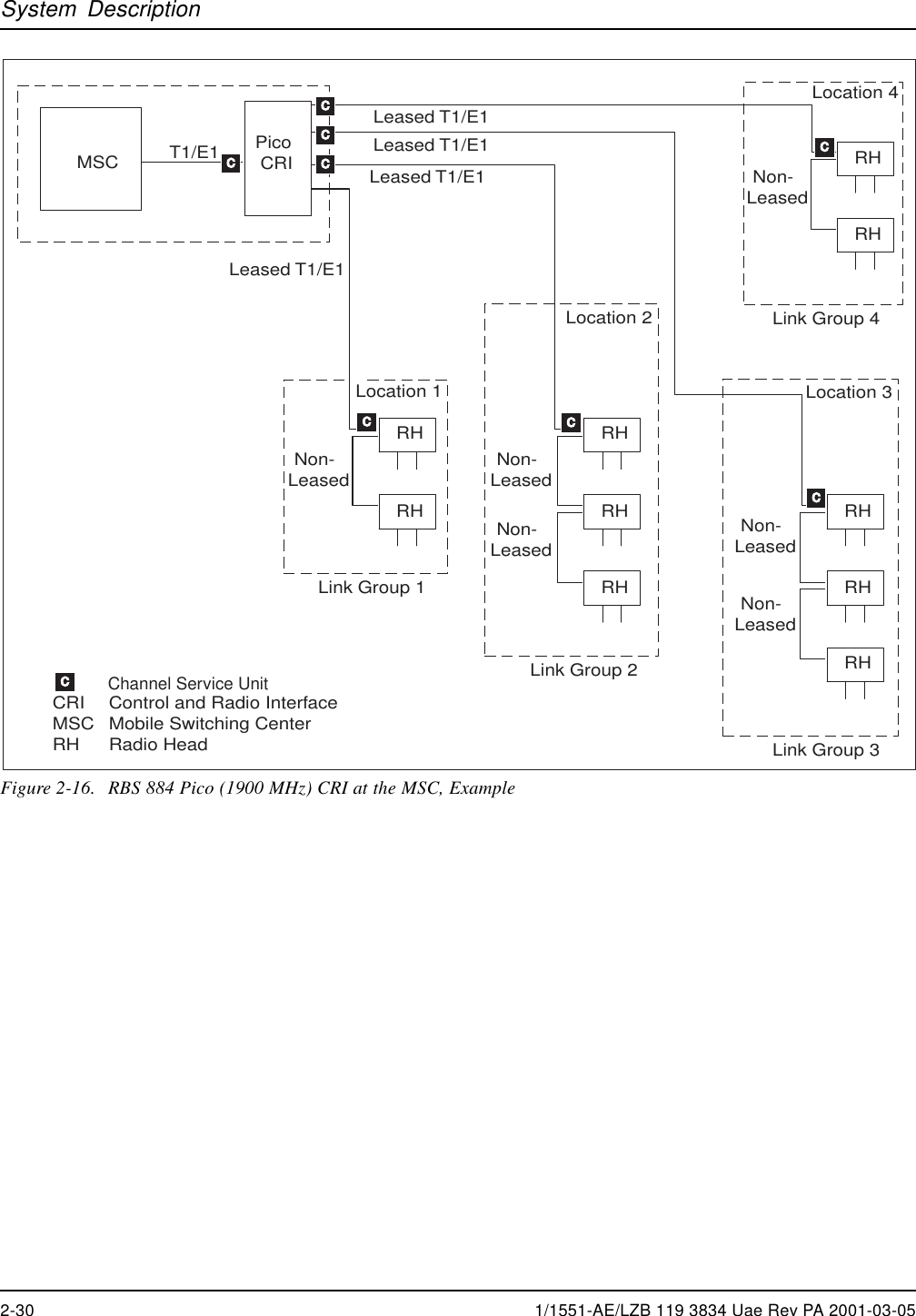
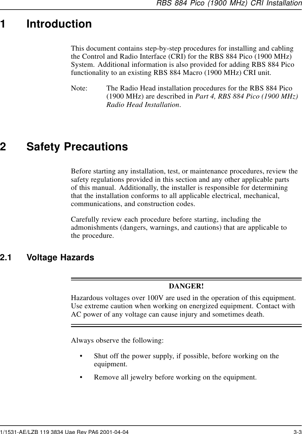
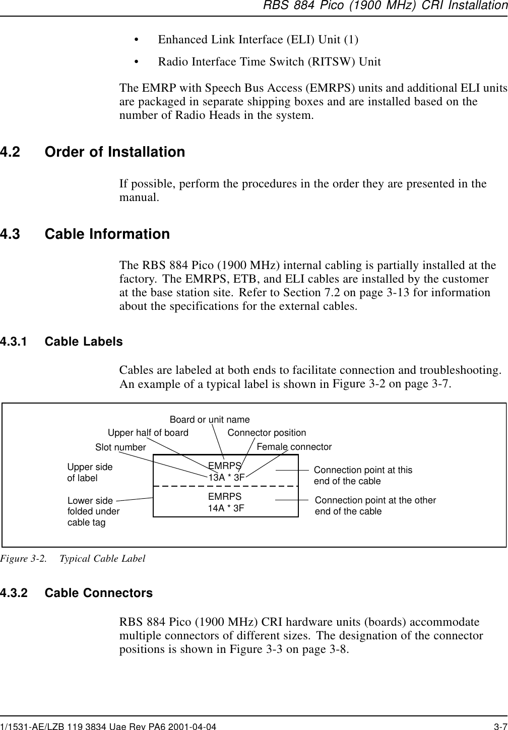
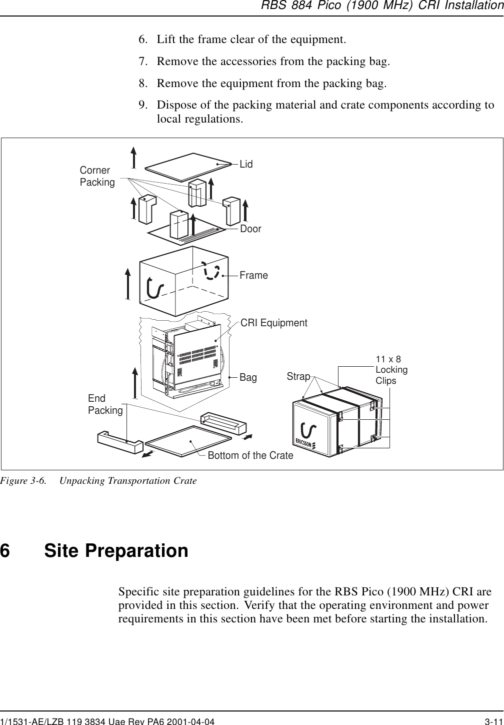
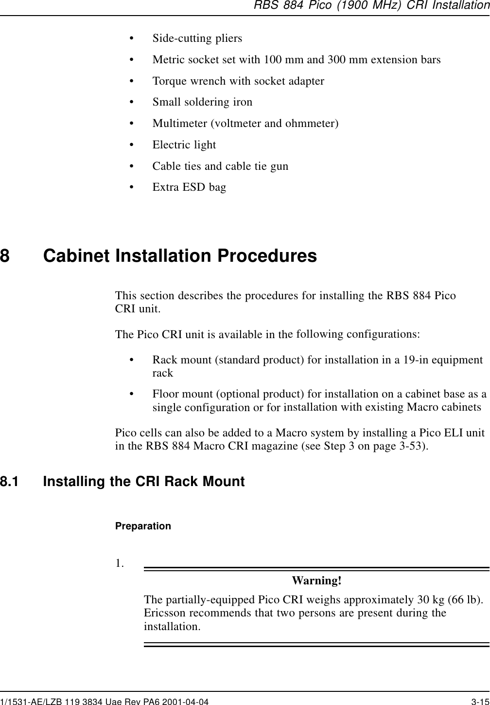
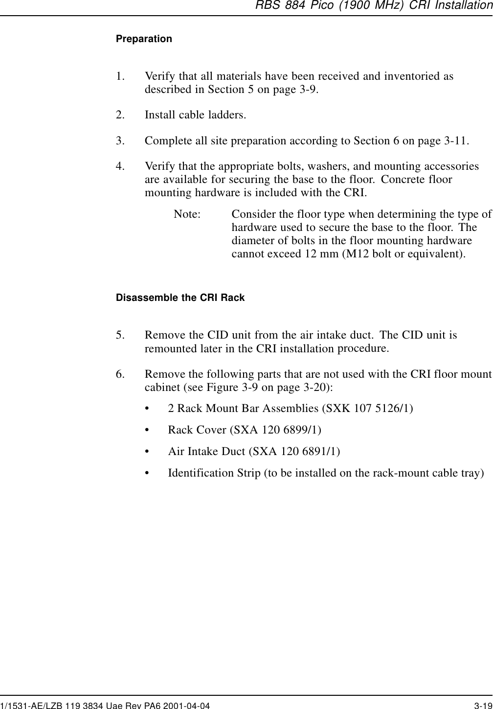
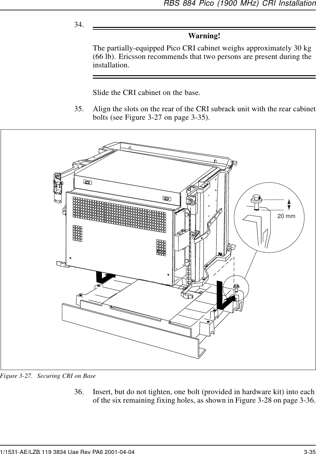
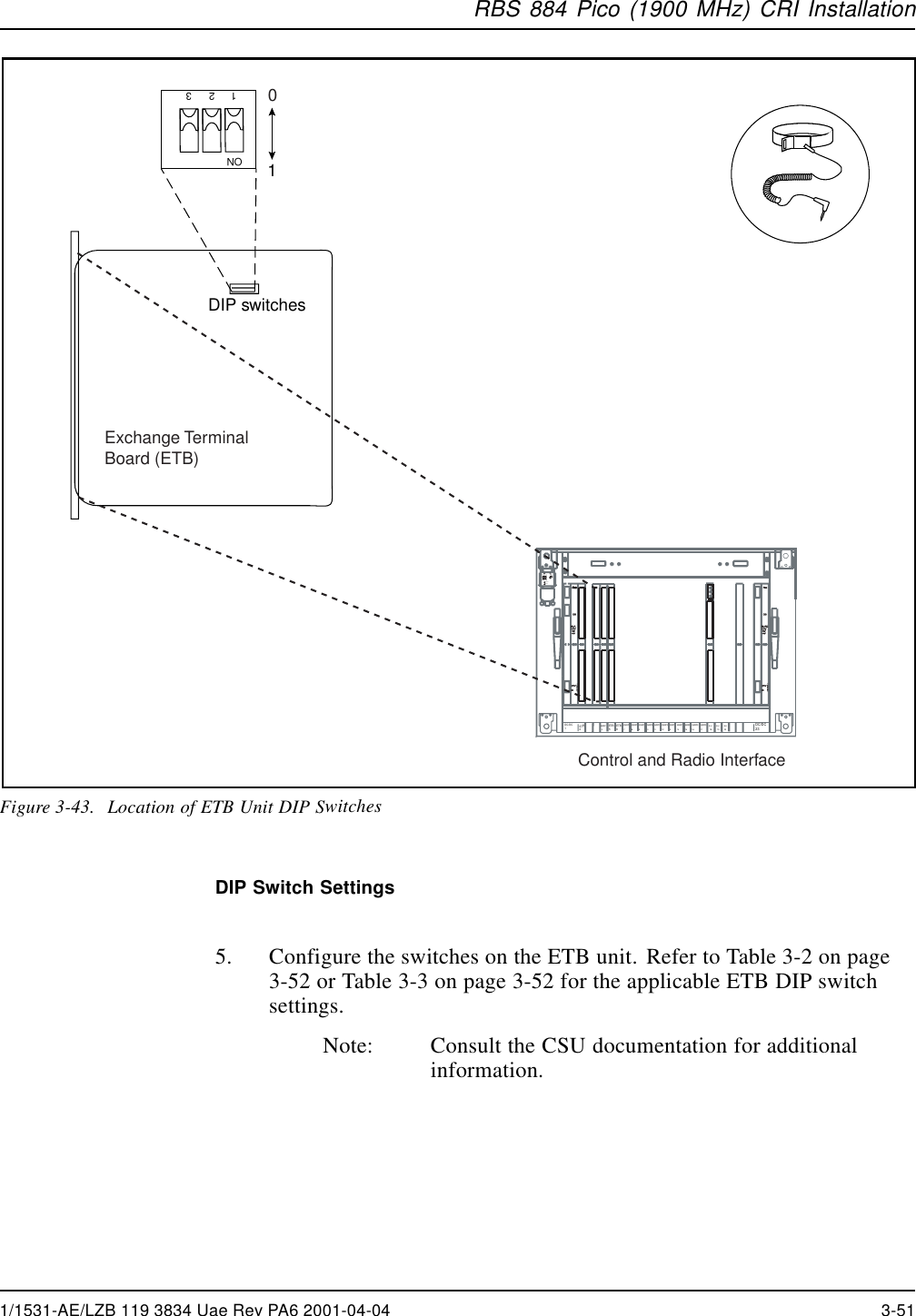
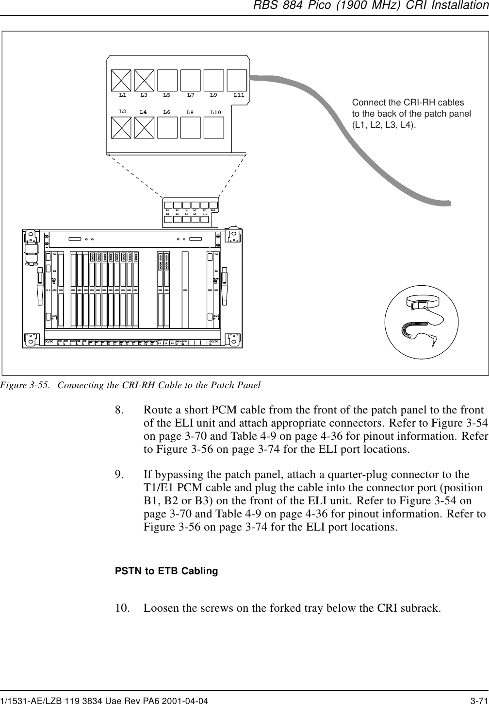
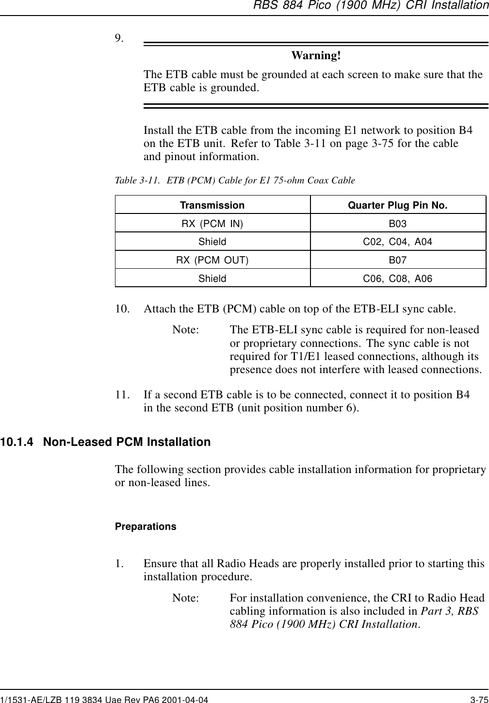
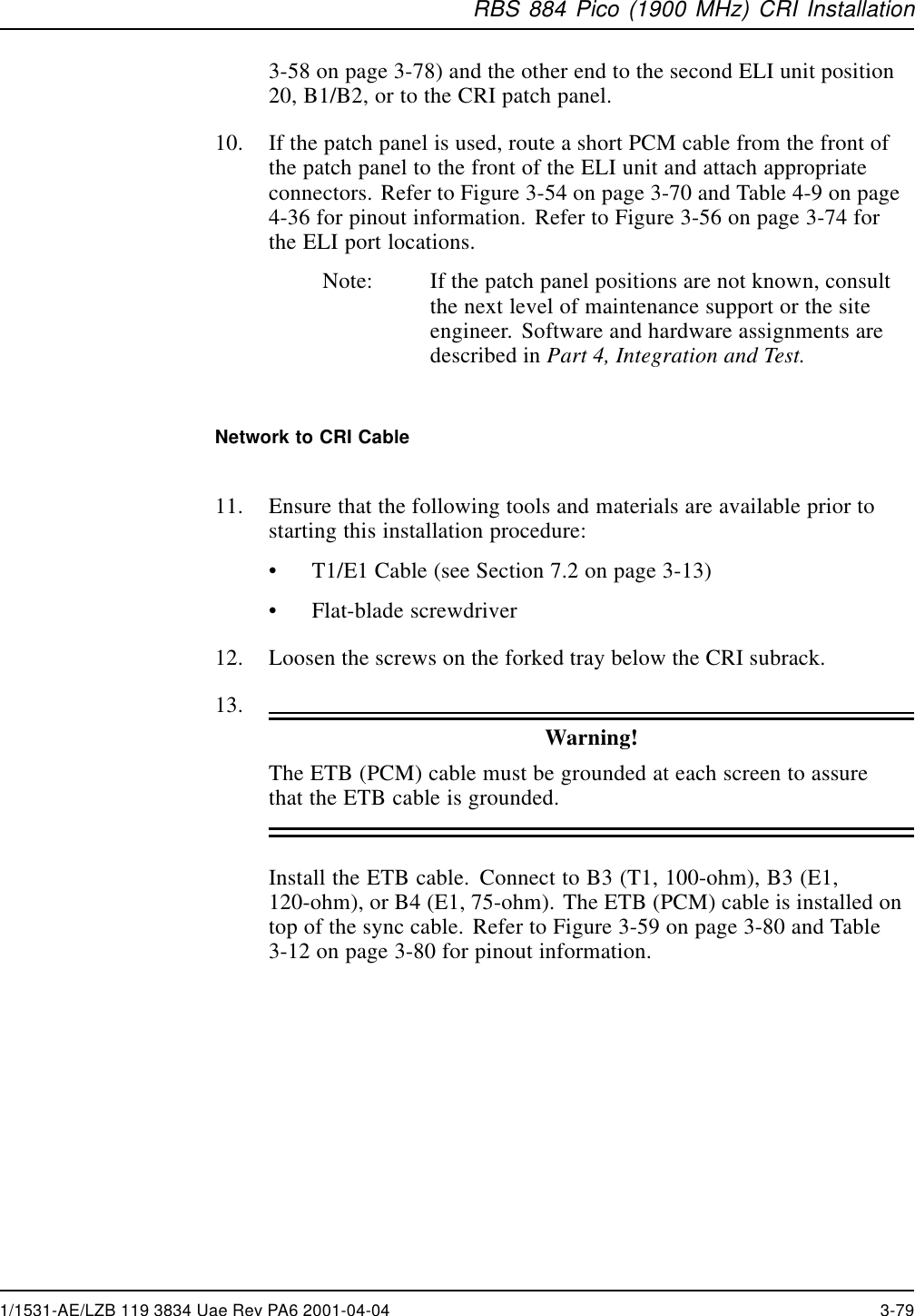
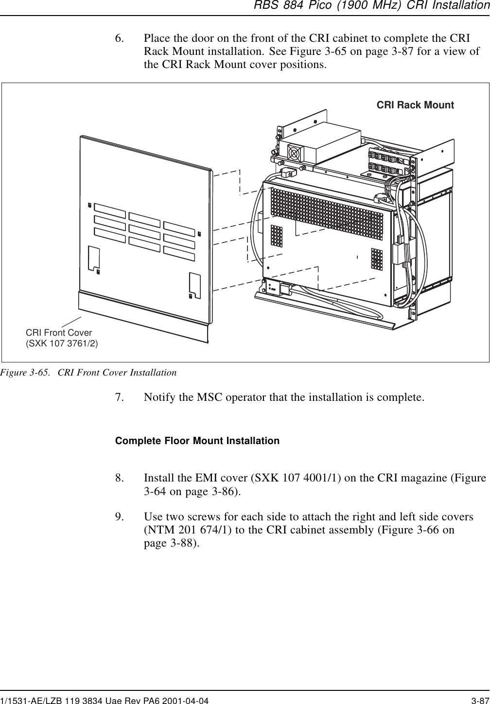
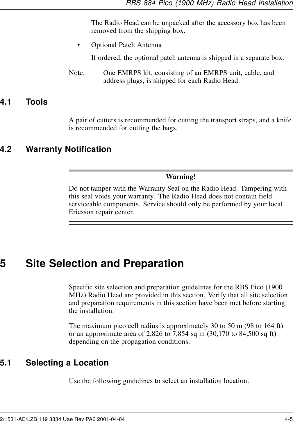
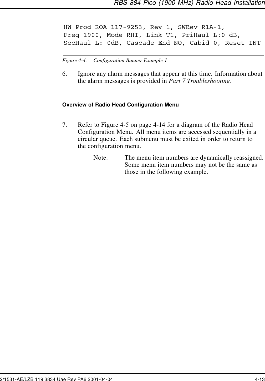
![RBS 884 Pico (1900 MHz) Radio Head InstallationTable 4-4. Configuration Program –Network MenuMenu Parameters Explanation Notes[ATT] AT&T Specificationfor maximumjitter/wanderamplitude is 138 UI.Configures theTiming Module(TIM)orPLLTypeNTWKBELL BellcoreSpecificationfor maximumjitter/wanderamplitude is 28 UI.Configures theTiming Module(TIM)orPLLTypeSetting the Cascade Position36. Press the SCROLL button until CASCAD appears.Note: Setting the cascade position disables the alarms onthe secondary T1/E1 network interface.37. Press the SELECT button and ENDY appears.38. Press the SELECT button to select the ENDY (End = Yes) parameter orpress the SCROLL button followed by the SELECT button to selectthe ENDN (End = No) parameter.Note: Pressing the SELECT button a second time deselectsthe parameter.39. Press the SCROLL button until exit appears, and press the SELECTbutton to exit the Cascade menu.2/1531-AE/LZB 119 3834 Uae Rev PA6 2001-04-04 4-19](https://usermanual.wiki/HARRIS/KRC121107-1/User-Guide-143185-Page-169.png)
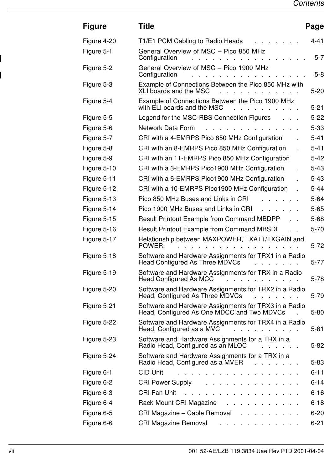
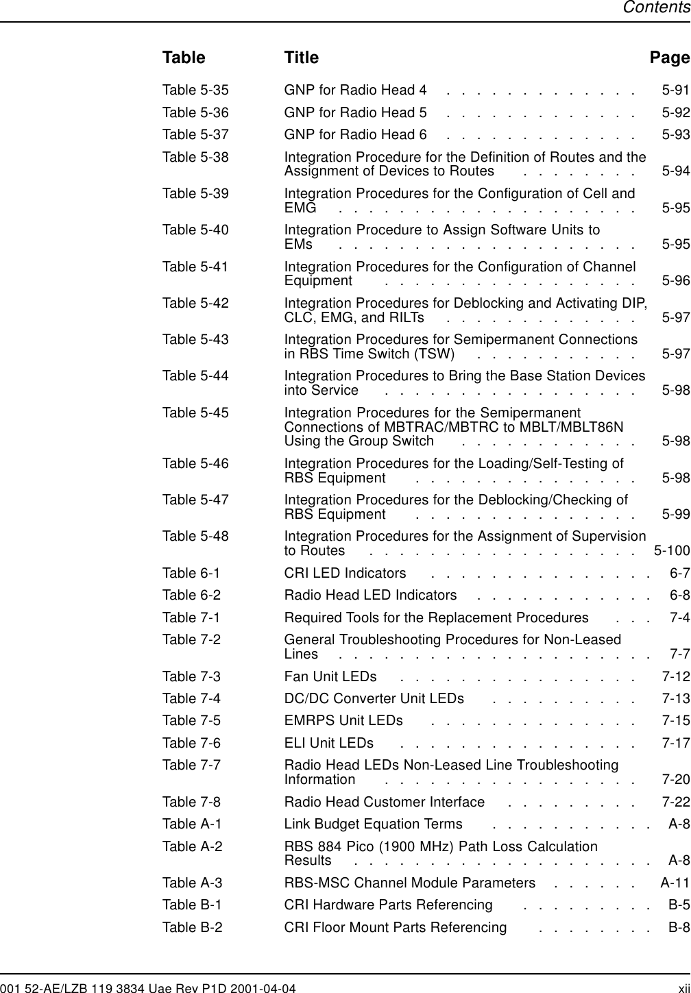
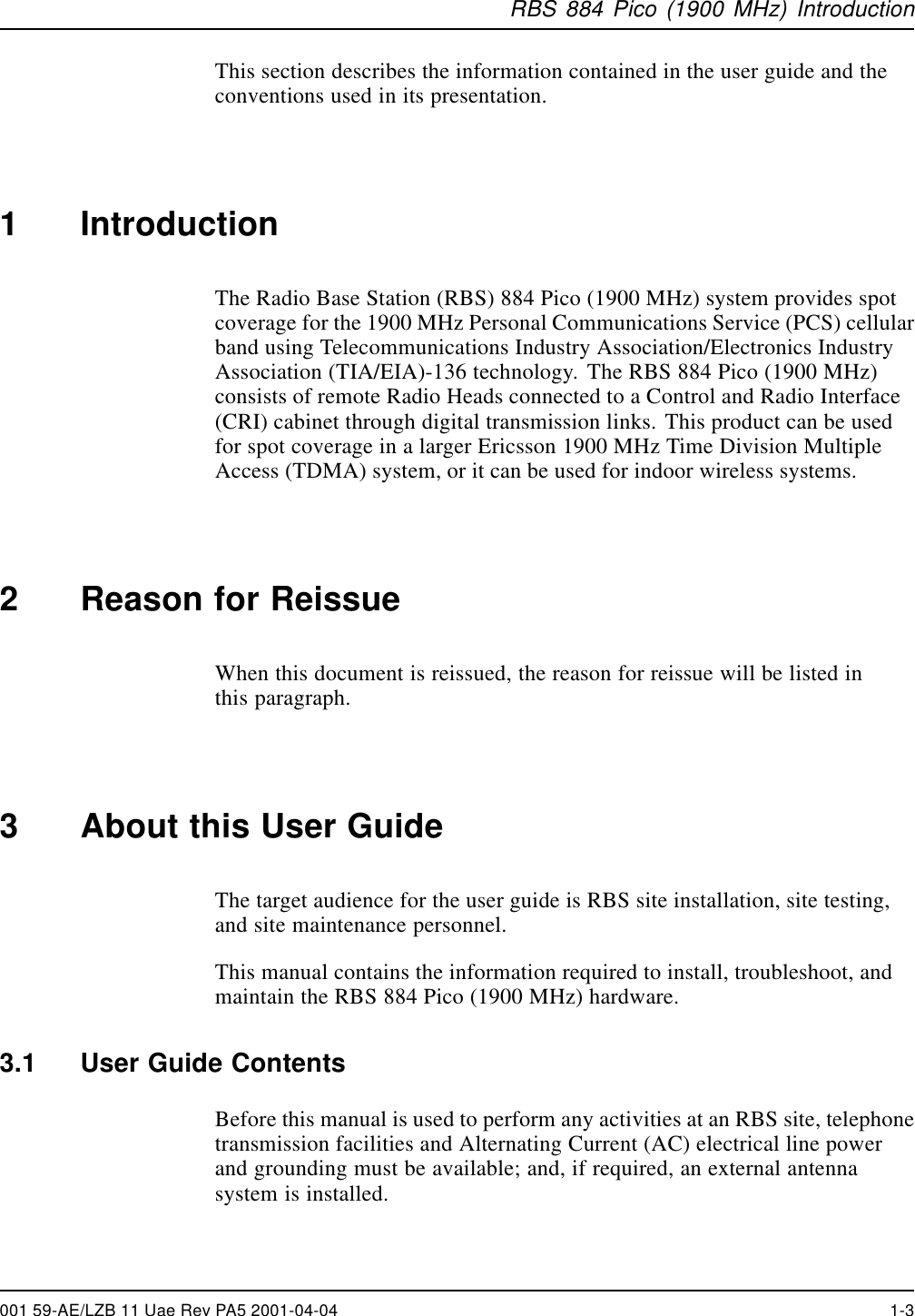
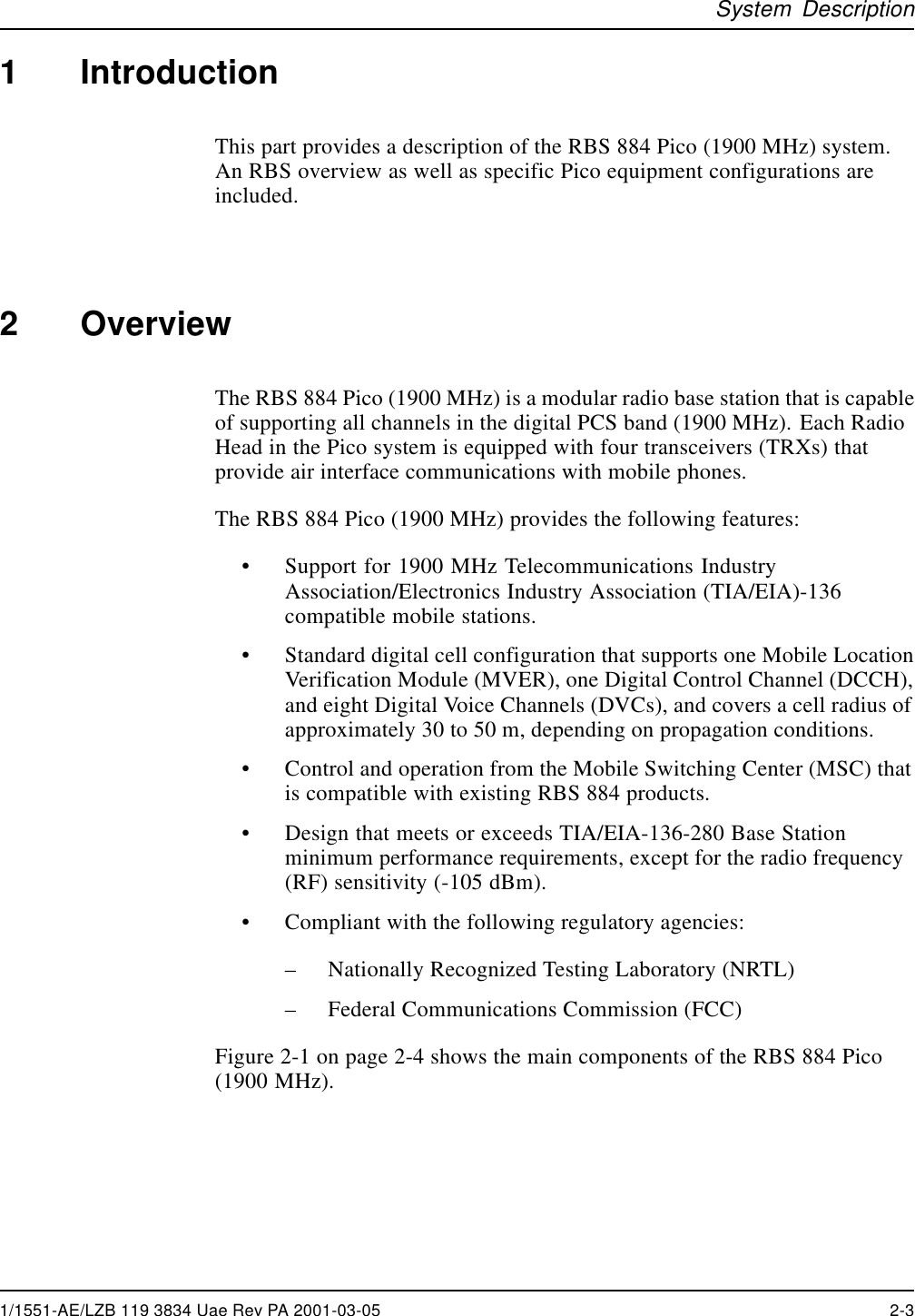
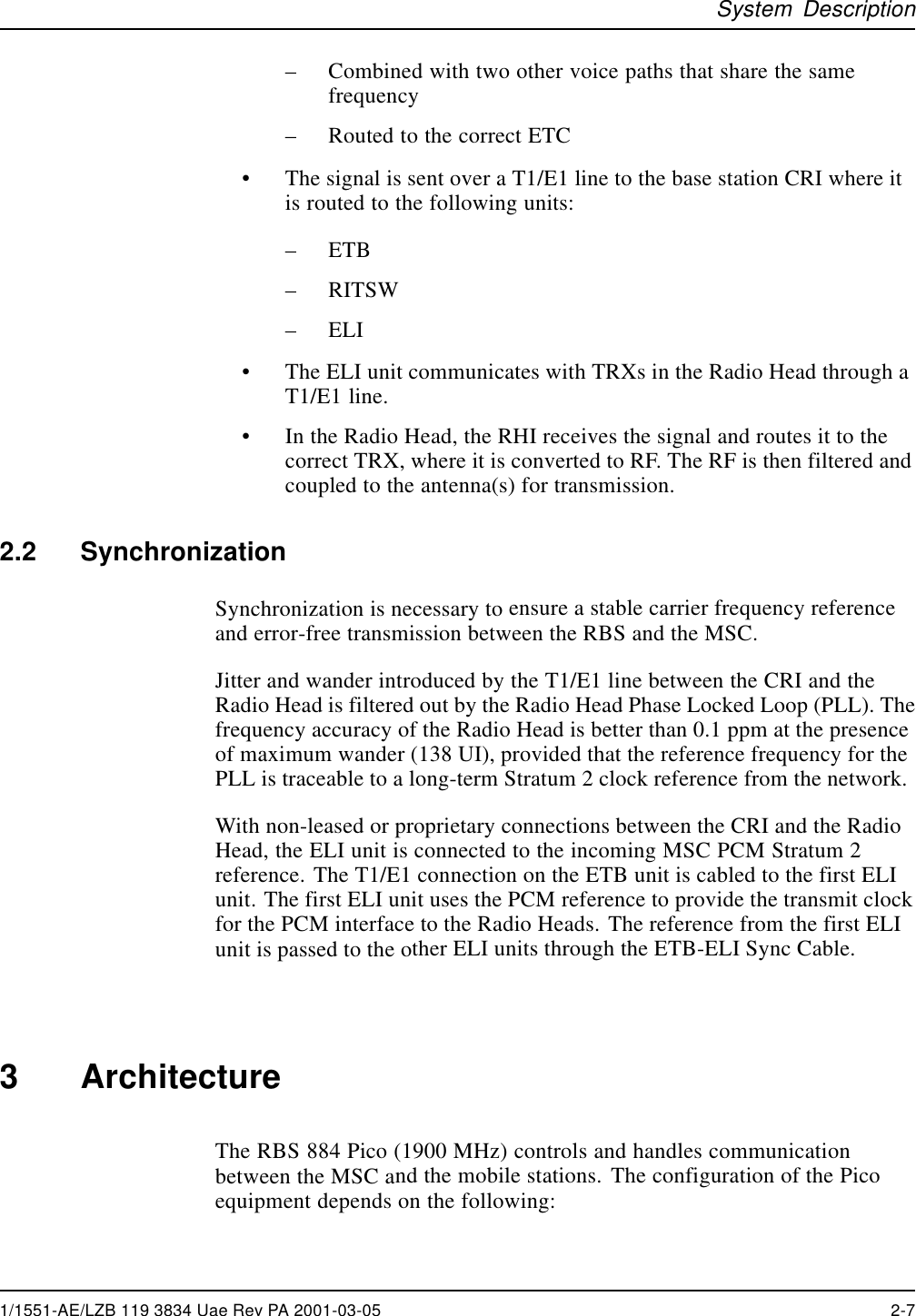
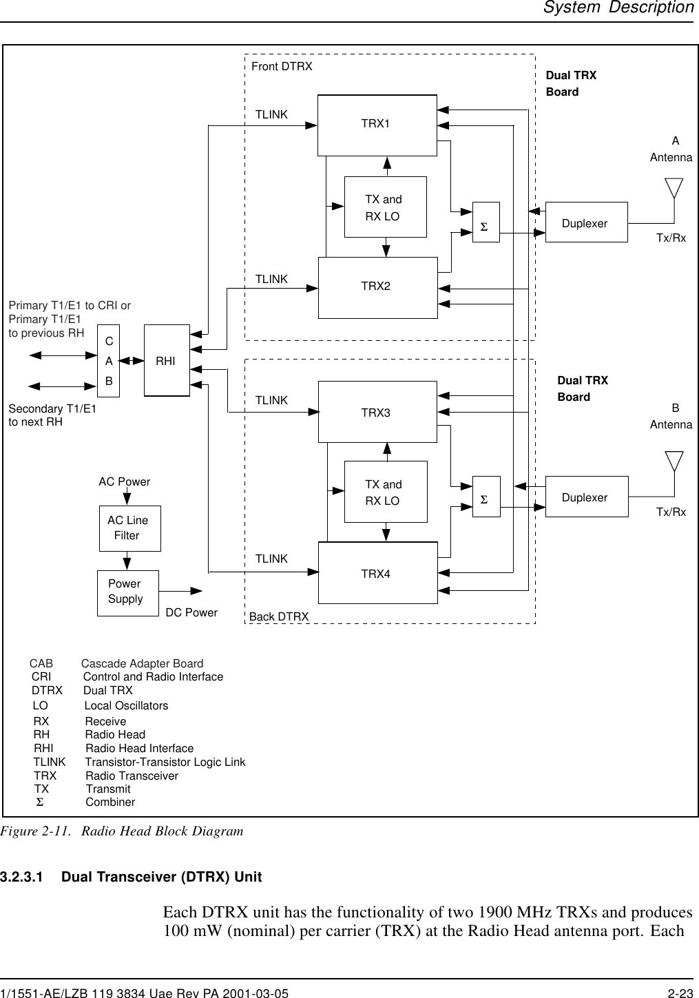
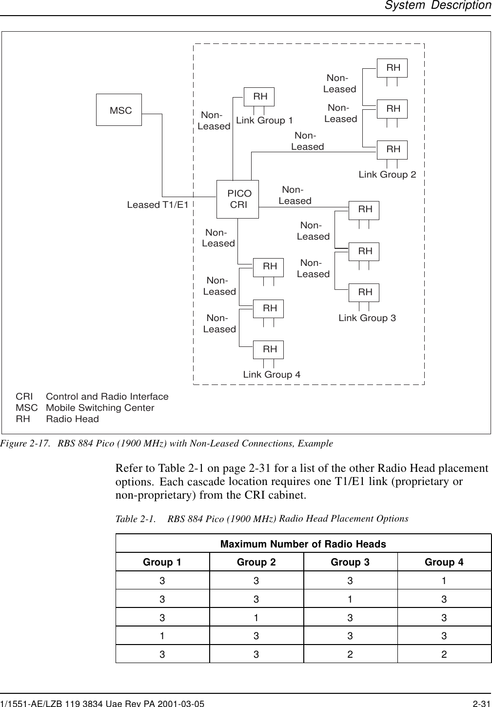
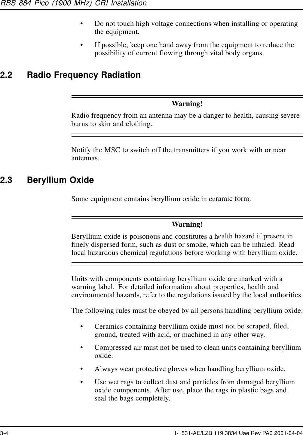
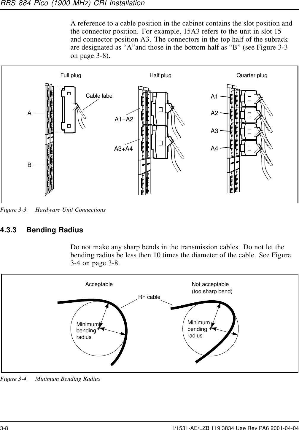
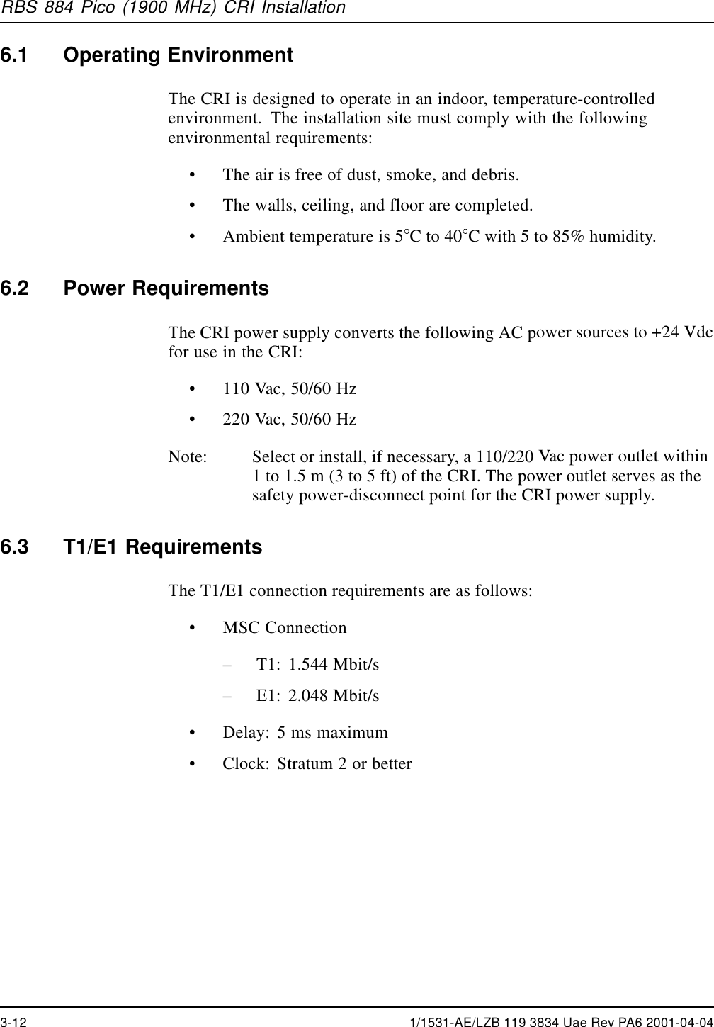
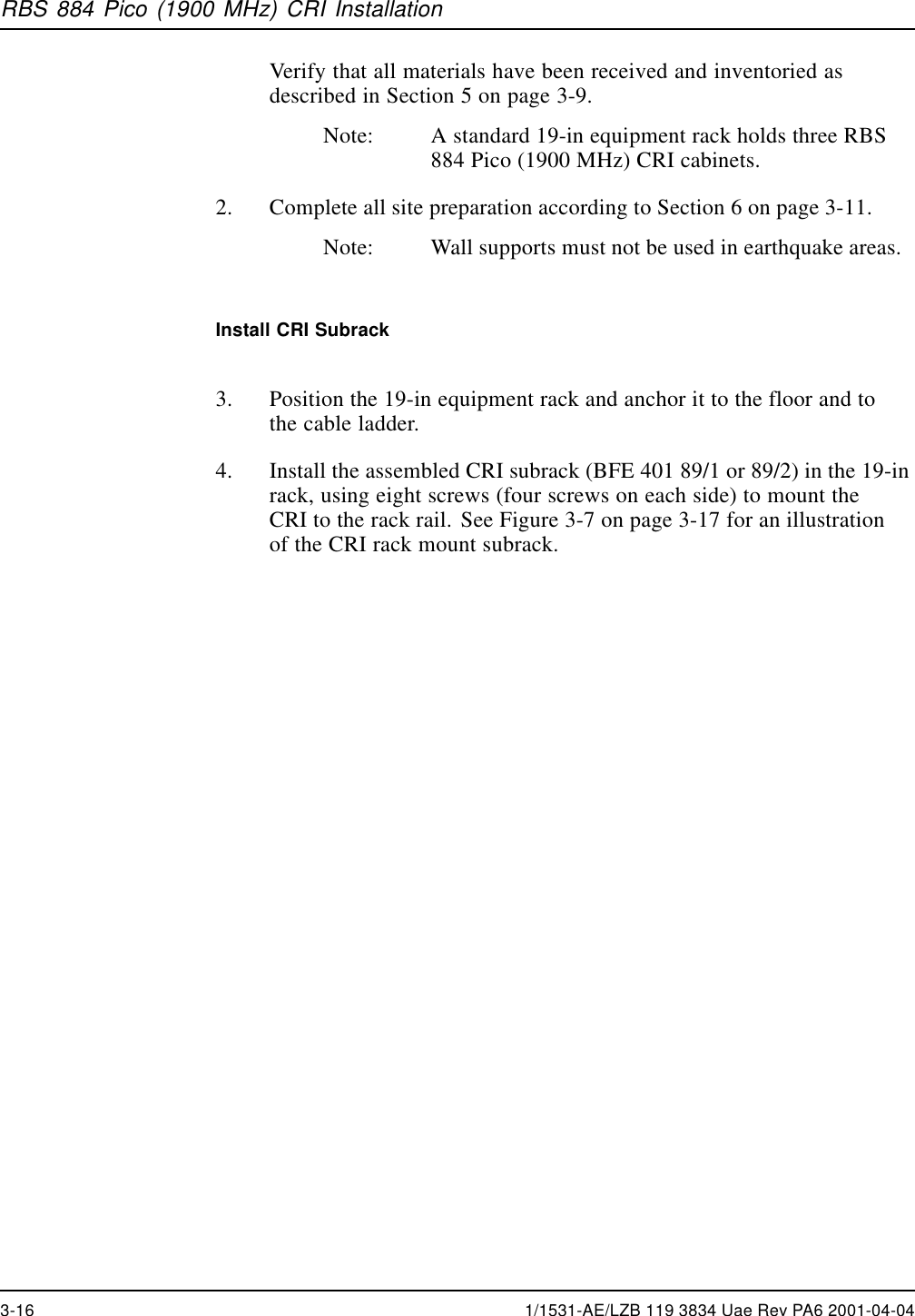
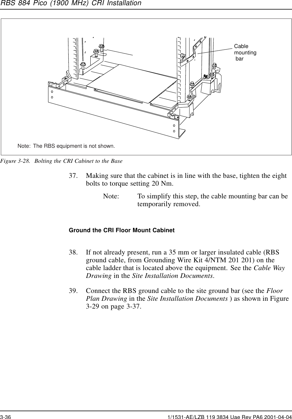
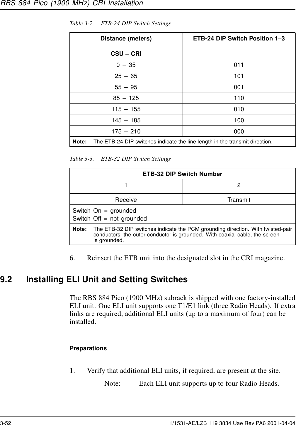
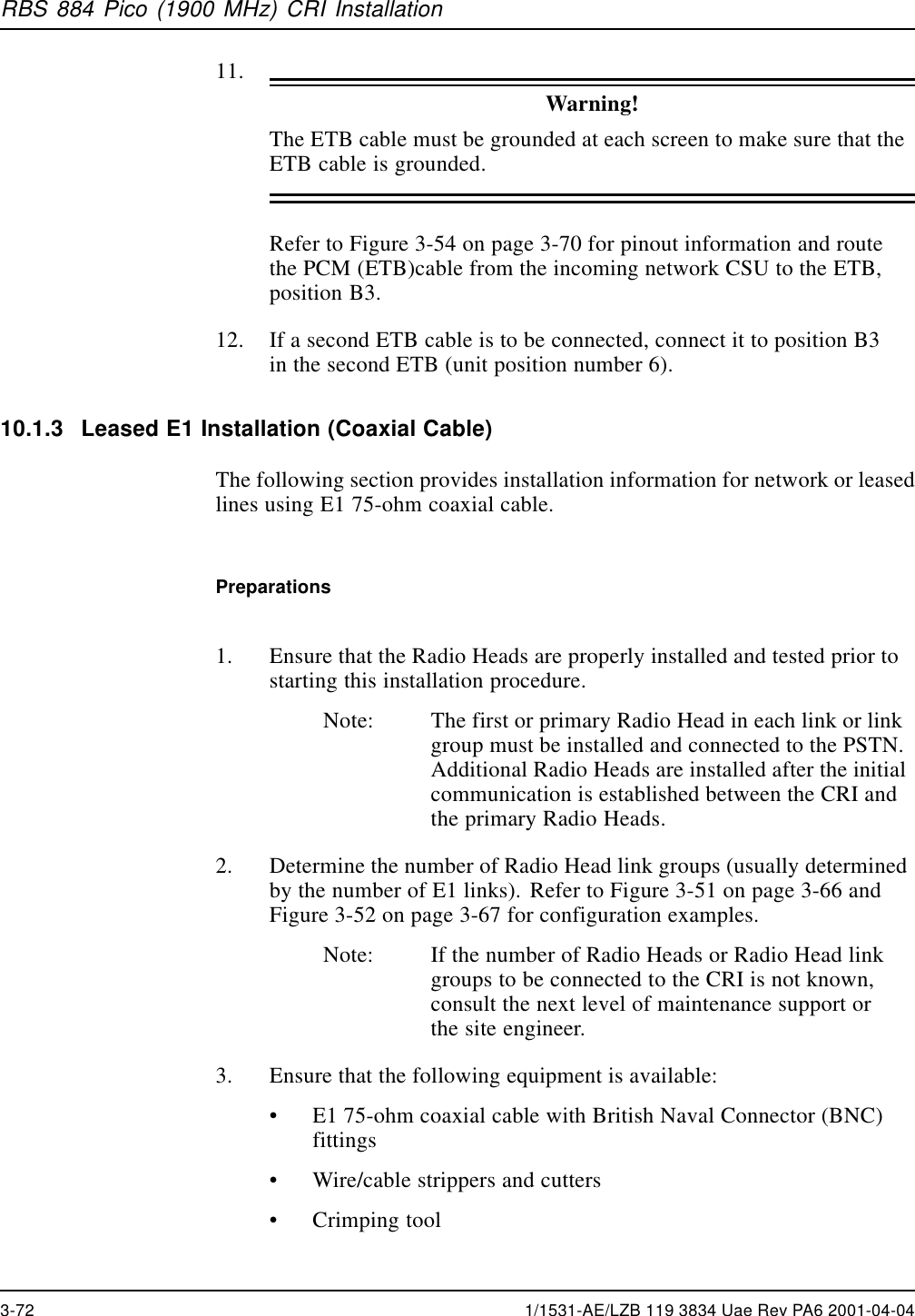
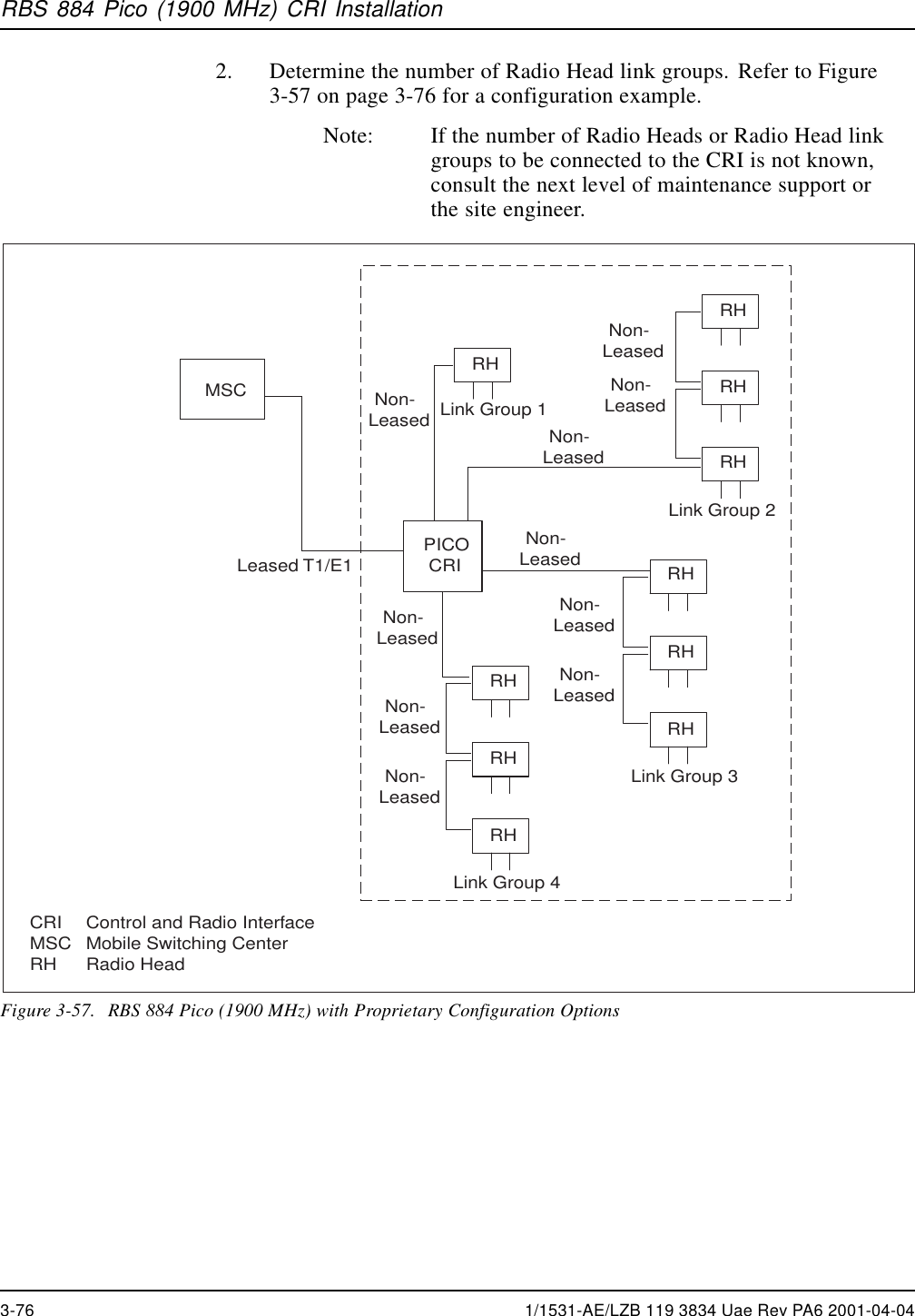
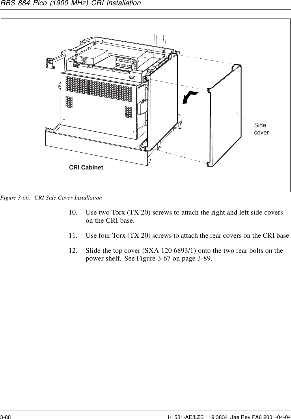
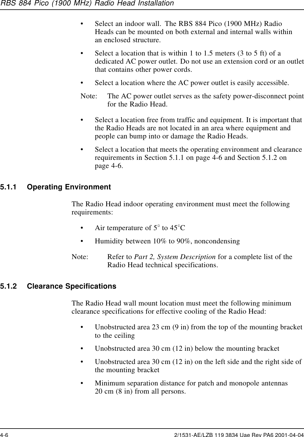
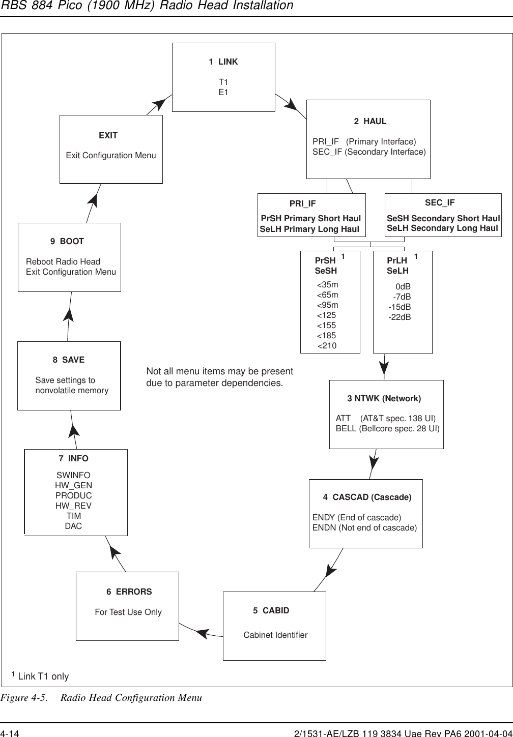
![RBS 884 Pico (1900 MHz) Radio Head InstallationTable 4-5. Configuration Program –Cascade MenuMenu Parameters Explanation NoteENDY Last cascadeposition = YesSecondary interfacealarms are ignoredby the Radio Head.CASCADENDN Last cascadeposition = NoSecondary interfacealarms aredisplayed by theRadio Head.Setting the Cabinet Identifier (CID)40. Press the SCROLL button until CABID appears.41. Press the SELECT button and 00 [00] appears. The brackets reflectthe current CID number.42. Call the MSC and request a CID number.43. Enter the Radio Head CID number by pressing the SCROLL button toincrease the first two digits from 00 to 15 in a circular manner. Thefirst two digits reflect the new CID number and the last two digitsreflect the factory default or current CID number.44. Press the SELECT button to accept the first two digits as the new unitID number and exit the Cabinet ID menu.Table 4-6. Configuration Program –Cabinet ID MenuMenu Parameters ExplanationCABID XX_[YY] XX is the new selected IDnumber (00–15).YY is the current IDnumber (00–15).4-20 2/1531-AE/LZB 119 3834 Uae Rev PA6 2001-04-04](https://usermanual.wiki/HARRIS/KRC121107-1/User-Guide-143185-Page-170.png)