HARRIS KRC121107-1 Base station User Manual exhibit 8
HARRIS CORPORATION Base station exhibit 8
HARRIS >
exhibit 8
E
RBS 884 Pico (1900 MHz) User Guide
AE/LZB 119 3834 P1D 2001-04-04 © Ericsson Radio Systems AB 2001 – All Rights Reserved

The contents of this document are subject to revision without notice due to
continued progress in methodology, design, and manufacturing.
Ericsson shall have no liability for any error or damages of any kind resulting
from the use of this document.
i 001 52-AE/LZB 119 3834 Uae Rev P1D 2001-04-04

Table of Contents
Part 1 RBS 884 Pico (1900 MHz) Introduction . . . . . . . . . 1-1
1 Introduction ................... 1-3
2 ReasonforReissue ............... 1-3
3 AboutthisUserGuide .............. 1-3
Part2 SystemDescription ................... 2-1
1 Introduction ................... 2-3
2 Overview .................... 2-3
3 Architecture ................... 2-7
4 Equipment Configurations . . . . . . . . . . . . 2-28
5 TechnicalData .................. 2-33
Part3 RBS884Pico(1900MHz)CRIInstallation ........ 3-1
1 Introduction ................... 3-3
2 SafetyPrecautions ................ 3-3
3 ElectrostaticDischarge .............. 3-5
4 GeneralInformation ............... 3-6
5 Unpacking .................... 3-9
6 SitePreparation ................. 3-11
7 PrerequisitesandTools .............. 3-13
8 Cabinet Installation Procedures . . . . . . . . . . 3-15
9 CRI Hardware Units and Switches . . . . . . . . . 3-50
10 Equipment Cabling and Start-up . . . . . . . . . . 3-62
Part 4 RBS 884 Pico (1900 MHz) Radio Head Installation . . . . 4-1
1 Introduction ................... 4-3
2 SafetyPrecautions ................ 4-3
3 GeneralInformation ............... 4-4
4 Unpacking .................... 4-4
5 SiteSelectionandPreparation .......... 4-5
6 PrerequisitesandTools .............. 4-8
7 RadioHeadSet-up ................ 4-9
8 EquipmentInstallation .............. 4-25
Part 5 Integration and Test, RBS 884 Pico (850 MHz and
1900MHz) ....................... 5-1
1 Introduction ................... 5-3
2 SafetyRegulations ................ 5-4
3 ProductHandling ................. 5-5
4 Tools ...................... 5-6
5 Integration:Pico850/1900MHz .......... 5-6
6 RBS 884 Pico CRI Test Procedure: Pico 850/1900
MHz ...................... 5-66
001 52-AE/LZB 119 3834 Uae Rev P1D 2001-04-04 ii

Contents
7 RBS 884 Pico Radio Head Test Procedure:
Pico850/1900MHz ............... 5-66
8 Installation Test Procedure: Pico 850/1900 MHz . . 5-67
9 Example Integration: Pico (850 MHz) . . . . . . . 5-76
10 Example Integration: Pico (1900 MHz) . . . . . . 5-157
Part6 OperationsandMaintenance .............. 6-1
1 Introduction ................... 6-3
2 MaintenanceOverview .............. 6-3
3 SafetyRegulations ................ 6-4
4 ProductHandling ................. 6-5
5 Fault Detection and Alarms Reporting . . . . . . . 6-6
6 HardwareReplacement .............. 6-9
Part 7 Troubleshooting . . . . . . . . . . . . . . . . . . . . 7-1
1 Introduction ................... 7-3
2 Troubleshooting ................. 7-3
3 PrerequisitesandTools .............. 7-4
4 FaultIsolationandRepair ............. 7-5
Part8 GlossaryofTerms ................... 8-1
Part9 AcronymsandAbbreviations .............. 9-1
AppendixA RFGuidelines ..................... A-1
1 Introduction ................... A-3
2 GeneralDescription ............... A-3
3 TransmissionPath ................ A-6
4 LinkBudget ................... A-7
5 Operations and Maintenance . . . . . . . . . . . A-9
Appendix B RBS 884 Pico (1900 MHz) Spare Parts Catalog . . . . . B-1
1 GeneralInformation ............... B-3
2 Product Location and Referencing . . . . . . . . . B-4
Appendix C Test Record Form for RBS 884 Pico . . . . . . . . . . . C-1
1 Introduction ................... C-3
2 TestRecordForms ................ C-3
AppendixD UserFeedback ..................... D-1
1 Introduction ................... E-1
2 OrderingofCustomerManuals .......... E-1
3 ProblemSolving ................. E-1
4 TroubleReporting ................ E-1
AppendixE ConversionTable .................... E-1
1 Introduction ................... E-3
2 ConversionTable ................ E-3
iii 001 52-AE/LZB 119 3834 Uae Rev P1D 2001-04-04

List of Figures
Figure Title Page
Figure2-1 RBS884Pico(1900MHz)Components ....... 2-4
Figure 2-2 General Overview of RBS 884 Pico (1900 MHz)
Configuration ................. 2-9
Figure 2-3 RBS 884 Pico (1900 MHz) Functional and Implementation
Units .................... 2-11
Figure2-4 CRIRackMountEquipment .......... 2-14
Figure2-5 CRIFloorMountEquipment .......... 2-15
Figure2-6 CRIFloorMountCabinetLayout ......... 2-16
Figure2-7 CRIInterconnections ............. 2-17
Figure2-8 ELIUnitwithCascadedRadioHeads ....... 2-19
Figure2-9 CRIInternalAlarmDistribution ......... 2-21
Figure2-10 RadioHeadwithMonopoleAntennas ....... 2-22
Figure2-11 RadioHeadBlockDiagram ........... 2-23
Figure2-12 RadioHeadMonopoleAntennas ......... 2-25
Figure2-13 RadioHeadDualPatchAntenna ......... 2-25
Figure2-14 RadioHeadUserInterface ........... 2-27
Figure 2-15 RBS 884 Pico (1900 MHz) with Leased Connections,
Example .................. 2-29
Figure 2-16 RBS 884 Pico (1900 MHz) CRI at the MSC, Example 2-30
Figure 2-17 RBS 884 Pico (1900 MHz) with Non-Leased Connections,
Example .................. 2-31
Figure2-18 MacroSitewithPicoELIandRadioHeads .... 2-33
Figure 3-1 ESD Wrist Strap and Cable Connected to the Cabinet . 3-6
Figure3-2 TypicalCableLabel ............... 3-7
Figure3-3 HardwareUnitConnections ............ 3-8
Figure3-4 MinimumBendingRadius ............ 3-8
Figure 3-5 Example of an N-Connector (Can also be Angled) . . 3-9
Figure3-6 UnpackingTransportationCrate ......... 3-11
Figure3-7 CRIRackMountSubrack ........... 3-17
Figure3-8 SettingtheCabinetIdentifier .......... 3-18
Figure3-9 CRIRackMount ............... 3-20
Figure3-10 MarkingtheFixingHoleLocations ........ 3-21
Figure 3-11 Anchor Bolt Spacing for RBS Pico Equipment Base . 3-21
Figure3-12 DrillingtheFixingHoles ............ 3-22
Figure3-13 InstallingtheBaseBolts ............ 3-23
Figure3-14 InsertingAnchorsintheDrilledHoles ....... 3-23
Figure3-15 LevelingtheRearoftheBase .......... 3-24
Figure 3-16 Leveling the Sides oftheBase ......... 3-25
Figure3-17 TighteningtheBaseBolts ........... 3-26
001 52-AE/LZB 119 3834 Uae Rev P1D 2001-04-04 iv

Contents
Figure Title Page
Figure3-18 OrderinwhichtoTightentheBaseBolts ..... 3-26
Figure3-19 HookingtheCableChuteontotheBase ...... 3-27
Figure3-20 CableShelfInstallation ............ 3-28
Figure3-21 CRICabinetCaptiveNutInstallation ....... 3-29
Figure3-22 RearPlateInstallation ............. 3-30
Figure3-23 FanUnitInstallation .............. 3-31
Figure3-24 CRISubrackInstallation ............ 3-32
Figure3-25 FanUnitandSubrackAdjustment ........ 3-33
Figure3-26 CIDUnitInstallation .............. 3-34
Figure3-27 SecuringCRIonBase ............. 3-35
Figure3-28 BoltingtheCRICabinettotheBase ....... 3-36
Figure3-29 ExampleofGroundCableConnection ...... 3-37
Figure3-30 CableLugCrimpedonGroundCable ....... 3-38
Figure3-31 GroundingthePicoCabinet(BYB502) ...... 3-38
Figure3-32 PowerShelfBrackets ............. 3-39
Figure3-33 PowerShelfInstallation ............ 3-40
Figure3-34 PowerCableInstallation ............ 3-41
Figure 3-35 Measuring the Correct Separation Between the Bases 3-43
Figure 3-36 Distance between the Bolt Head and the Base . . . 3-44
Figure3-37 ContactBar ................. 3-45
Figure 3-38 Distance between Bolt Head and Cabinet Top . . . 3-46
Figure3-39 SlidingCabinetintoPositiononCabinet ...... 3-47
Figure3-40 InsertingBoltsinCabinetRowsC,D,orE ..... 3-48
Figure 3-41 Inserting Bolts in the Front Fixing Holes for Rows C, D, or
E ..................... 3-48
Figure3-42 MountingtheContactBar ........... 3-49
Figure3-43 LocationofETBUnitDIPSwitches ........ 3-51
Figure3-44 ELIUnitandSwitchLocation .......... 3-54
Figure3-45 IdentificationofELIUnitDIPSwitches ...... 3-55
Figure 3-46 RBS 884 Pico (1900 MHz)CRI (as delivered) . . . . 3-58
Figure3-47 PicoCRIEMRPSPositions ........... 3-59
Figure3-48 MacroCRIEMRPSPositions .......... 3-60
Figure 3-49 ELI Unit, Plugs, and Cables in CRI Cabinet . . . . 3-61
Figure 3-50 Connecting the ETB-ELI Sync Cable to Three ELI
Units .................... 3-64
Figure 3-51 RBS 884 Pico (1900 MHz) Configuration Example 1
(LeasedLines) ................ 3-66
Figure 3-52 RBS 884 Pico (1900 MHz) Configuration Example 2
(LeasedLines) ................ 3-67
Figure3-53 T1/E1PCMCablingtoRadioHeads ....... 3-69
v 001 52-AE/LZB 119 3834 Uae Rev P1D 2001-04-04

Contents
Figure Title Page
Figure3-54 PCMConnector(100/120-ohm)Pinouts ...... 3-70
Figure 3-55 Connecting the CRI-RH Cable to the Patch Panel . . 3-71
Figure3-56 ELIUnitandConnectorPositions ........ 3-74
Figure 3-57 RBS 884 Pico (1900 MHz) with Proprietary Configuration
Options ................... 3-76
Figure 3-58 Location of Radio Head PCM Interface Connector
Ports .................... 3-78
Figure 3-59 Pinout Connections for 100/120-ohm Screened, Twisted
pairCable .................. 3-80
Figure3-60 DC/DCConverterUnits ............ 3-82
Figure3-61 RadioHeadUserInterface ........... 3-84
Figure3-62 InstallingRadioHeadCover .......... 3-85
Figure3-63 InsertingEMCProtectionBlanks ......... 3-86
Figure3-64 EMICoverInstallation ............. 3-86
Figure3-65 CRIFrontCoverInstallation .......... 3-87
Figure3-66 CRISideCoverInstallation ........... 3-88
Figure3-67 CRITopCoverandDoorInstallation ....... 3-89
Figure4-1 MountingBracketClearanceSpecifications ..... 4-7
Figure4-2 RadioHeadCustomerInterface ......... 4-10
Figure 4-3 Radio Head AC Power Cord and AC Receptacle . . 4-12
Figure4-4 ConfigurationBannerExample1 ......... 4-13
Figure 4-5 Radio Head ConfigurationMenu ......... 4-14
Figure4-6 ConfigurationBannerExample2 ......... 4-23
Figure 4-7 Radio Head Interface Ports and DIP Switches . . . 4-24
Figure4-8 DisconnectingtheMonopoleAntennaCable .... 4-26
Figure4-9 MonopoleAntennaBracketAssembly ...... 4-27
Figure4-10 RadioHeadMountingBracket .......... 4-28
Figure4-11 AttachingRadioHeadtoMountingBracket .... 4-29
Figure 4-12 Radio Head Mounting Bracket with Tamper-Resistant
Screws ................... 4-30
Figure 4-13 Patch Antenna to DuplexerCables ........ 4-31
Figure4-14 PatchAntennaAssemblyandCables ....... 4-32
Figure 4-15 Impedance Matching Network for E1 75-ohm Coaxial
Cable ................... 4-34
Figure4-16 Pinoutsfor100/120-ohmPCMCable ....... 4-36
Figure 4-17 Primary PCM Interface Connector Location on Radio
Head .................... 4-38
Figure4-18 AttachingCableFerrites ............ 4-39
Figure 4-19 Radio Head AC Power Cord and AC Receptacle . . 4-40
001 52-AE/LZB 119 3834 Uae Rev P1D 2001-04-04 vi

Contents
Figure Title Page
Figure4-20 T1/E1PCMCablingtoRadioHeads ....... 4-41
Figure 5-1 General Overview of MSC – Pico 850 MHz
Configuration ................. 5-7
Figure 5-2 General Overview of MSC –Pico 1900 MHz
Configuration ................. 5-8
Figure 5-3 Example of Connections Between the Pico 850 MHz with
XLIboardsandtheMSC ............ 5-20
Figure 5-4Example of Connections Between the Pico 1900 MHz
withELIboardsandtheMSC .......... 5-21
Figure 5-5 Legend for the MSC-RBS Connection Figures . . . 5-22
Figure5-6 NetworkDataForm .............. 5-33
Figure 5-7 CRI with a 4-EMRPS Pico 850 MHz Configuration . 5-41
Figure 5-8 CRI with an 8-EMRPS Pico 850 MHz Configuration . 5-41
Figure 5-9 CRI with an 11-EMRPS Pico 850 MHz Configuration 5-42
Figure 5-10 CRI with a 3-EMRPS Pico1900 MHz Configuration . 5-43
Figure 5-11 CRI with a 6-EMRPS Pico1900 MHz Configuration . 5-43
Figure 5-12 CRI with a 10-EMRPS Pico1900 MHz Configuration . 5-44
Figure5-13 Pico850MHzBusesandLinksinCRI ...... 5-64
Figure5-14 Pico1900MHzBusesandLinksinCRI ...... 5-65
Figure 5-15 Result Printout Example from Command MBDPP . . 5-68
Figure 5-16 Result Printout Example from Command MBSDI . . 5-70
Figure 5-17 Relationship between MAXPOWER, TXATT/TXGAIN and
POWER. .................. 5-72
Figure 5-18 Software and Hardware Assignments for TRX1 in a Radio
HeadConfiguredAsThreeMDVCs ....... 5-77
Figure 5-19 Software and Hardware Assignments for TRX in a Radio
HeadConfiguredAsMCC ........... 5-78
Figure 5-20 Software and Hardware Assignments for TRX2 in a Radio
Head,ConfiguredAsThreeMDVCs ....... 5-79
Figure 5-21 Software and Hardware Assignments for TRX3 in a Radio
Head, Configured As One MDCC and Two MDVCs . 5-80
Figure 5-22 Software and Hardware Assignments for TRX4 in a Radio
Head,ConfiguredasaMVC .......... 5-81
Figure 5-23 Software and Hardware Assignments for a TRX in a
RadioHead,ConfiguredasanMLOC ...... 5-82
Figure 5-24 Software and Hardware Assignments for a TRX in a
RadioHead,ConfiguredasaMVER ....... 5-83
Figure6-1 CIDUnit .................. 6-11
Figure6-2 CRIPowerSupply .............. 6-14
Figure6-3 CRIFanUnit ................. 6-16
Figure6-4 Rack-MountCRIMagazine ........... 6-18
Figure 6-5 CRI Magazine –CableRemoval ......... 6-20
Figure6-6 CRIMagazineRemoval ............ 6-21
vii 001 52-AE/LZB 119 3834 Uae Rev P1D 2001-04-04

Contents
Figure Title Page
Figure6-7 CRIDC/DCConverterUnitRemoval ....... 6-24
Figure6-8 STRUnitRemoval .............. 6-28
Figure6-9 EMRPSUnitRemoval ............. 6-31
Figure6-10 RITSWUnitRemoval ............. 6-34
Figure6-11 ETBUnitRemoval .............. 6-36
Figure6-12 ELIUnitRemoval ............... 6-39
Figure6-13 RadioHeadFrontCover ............ 6-42
Figure6-14 RadioHeadConnectors ............ 6-43
Figure 6-15 Radio Head Patch Antenna Cables and External
Duplexers .................. 6-44
Figure6-16 RadioHeadPatchAntennaAssembly ...... 6-45
Figure 6-17 Radio Head with Mounting Bracket and Mounting
Screws ................... 6-46
Figure 6-18 Removing Radio Head from Mounting Bracket . . . 6-47
Figure6-19 AttachingRadioHeadtoMountingBracket .... 6-48
Figure6-20 RadioHeadCustomerInterfaceandLEDs ..... 6-49
Figure6-21 RadioHeadCustomerInterface ......... 6-51
Figure7-1 CRIRackMountandFloorMountCIDUnit ..... 7-9
Figure 7-2 Troubleshooting Flowchart for Cabinet Identification Unit
andPowerProblems ............. 7-10
Figure7-3 CRIPowerCableDiagram ........... 7-11
Figure7-4 DC/DCConverterUnitLEDs .......... 7-13
Figure7-5 EMRPSUnitLEDs .............. 7-15
Figure7-6 ELIUnitLEDs ................ 7-17
Figure7-7 RadioHeadLEDsandCustomerInterface ..... 7-19
FigureA-1 RBS884Pico(1900MHz)Configuration ...... A-4
FigureA-2 RadioHeadTransmissionPath .......... A-6
FigureB-1 CRIHardwareParts ............... B-5
FigureB-2 CRIFloorMountParts .............. B-7
FigureB-3 RBS884Pico(1900MHz)CRIBoards ....... B-9
FigureB-4 RBS884Pico(1900MHz)RadioHeadKit ..... B-11
FigureB-5 RadioHeadPatchAntennaKit ......... B-12
Figure B-6 ETB-ELI Sync Cable and Impedance Matching
Network ................... B-13
Figure C-1 RBS 884 Pico Test Record –Page1 ........ C-4
Figure C-2 RBS 884 Pico Test Record –Page2 ........ C-5
001 52-AE/LZB 119 3834 Uae Rev P1D 2001-04-04 viii

Contents
ix 001 52-AE/LZB 119 3834 Uae Rev P1D 2001-04-04

List of Tables
Table Title Page
Table 2-1 RBS 884 Pico (1900 MHz) Radio Head Placement
Options ................... 2-31
Table2-2 RBS884Pico(1900MHz)Capacity ....... 2-34
Table 2-3 RBS 884 Pico (1900 MHz) Technical Specifications . 2-34
Table 2-4 RBS 884 Pico (1900 MHz) Certification Specifications 2-38
Table 3-1 Technical Data –ExpanderBolt ......... 3-22
Table3-2 ETB-24DIPSwitchSettings .......... 3-52
Table3-3 ETB-32DIPSwitchSettings .......... 3-52
Table3-4 DIPSwitchesT1Leased ........... 3-55
Table3-5 ELIDIPSwitchSettingsE1Leased ....... 3-56
Table 3-6 ELI DIP Switch Settings for T1 Proprietary or
Non-Leased ................. 3-56
Table 3-7 ELI DIP Switch Settings for E1 Proprietary or
Non-Leased ................. 3-57
Table3-8 EMRPSBusCableLabels ........... 3-62
Table3-9 PCMConnectionSpecifications ......... 3-69
Table3-10 Pinoutsfor100/120-ohmTwistedPairCable .... 3-70
Table 3-11 ETB (PCM) Cable for E1 75-ohm Coax Cable . . . 3-75
Table 3-12 ETB (PCM) Cable for E1 75-ohm Coax Cable . . . 3-80
Table4-1 ToolsforInstallingRadioHead .......... 4-9
Table 4-2 Configuration Program –LinkMenu ....... 4-15
Table 4-3 Configuration Program –HaulMenu ....... 4-17
Table 4-4 Configuration Program –NetworkMenu ...... 4-19
Table 4-5 Configuration Program –CascadeMenu ..... 4-20
Table 4-6 Configuration Program –CabinetIDMenu ..... 4-20
Table 4-7 Configuration Program –InformationMenu .... 4-22
Table4-8 PCMConnectionSpecifications ......... 4-35
Table 4-9 Pinouts for 100/120–ohmPCMCable ....... 4-36
Table 4-10 E1 Pinouts for 120-ohm PCM Cable and Impedance
MatchingNetwork .............. 4-37
Table 5-1 TRAB2 and TRAB3 Terminology Comparison . . . . 5-4
Table5-2 ETBTimeSlotUse .............. 5-17
Table 5-3 Pico 850/1900 MHz Digital-Only Radio Head
Configuration ................ 5-35
Table 5-4 Pico 850/1900 MHz Digital-Only Configuration with Radio
Head1andEMRPS1 ............. 5-36
Table 5-5 Pico 850/1900 MHz Digital-Only Configuration with Radio
Head2andEMRPS2 ............. 5-36
Table 5-6 Analog-Only Single Radio Head Configuration (Analog
Gateway) .................. 5-37
001 52-AE/LZB 119 3834 Uae Rev P1D 2001-04-04 x

Contents
Table Title Page
Table 5-7 Pico 850 MHz Analog-Only Two Radio Head Configuration
(AnalogGateway)withRadioHead1 ....... 5-38
Table 5-8 Pico 850 MHz Analog-Only Two Radio Head Configuration
(AnalogGateway)withRadioHead2 ....... 5-38
Table 5-9 Pico 850 MHz Analog-Only Two Radio Head Configuration
(Analog Gateway) with Radio Head 1 and EMRPS 1 . 5-39
Table 5-10 Pico 850 MHz Analog-Only Two Radio Head Configuration
(Analog Gateway) with Radio Head 2 and EMRPS 2 . 5-39
Table 5-11 Pico 850 MHz Dual Mode Radio Head Configuration with
Radio Head 1 (Analog and Digital) and EMRPS 1 . . 5-40
Table 5-12 Pico 850 MHz Dual Mode Radio Head Configuration with
RadioHead2(Analog)andEMRPS2 ...... 5-40
Table5-13 Pico850MHzCFUFunctions .......... 5-45
Table 5-14 Pico 850 MHz EMRPS Load from Different CFUs . . 5-45
Table 5-15 Pico 850 MHz T1A/E1A 553 Compatible with 4 Analog
Cellsand8RadioHeads,Example ........ 5-46
Table 5-16 Pico 850 MHz T1A/E1A 553 Compatible with 5 Analog
Cellsand8RadioHeads,Example ........ 5-47
Table 5-17 Pico 850 MHz IS-136 Compatible with 11 Digital Cells and
11RadioHeads,Example1 .......... 5-47
Table 5-18 Pico 850 MHz IS-136 Compatible with 11 Digital Cells and
11RadioHeads,Example2 .......... 5-48
Table 5-19 Pico 850 MHz IS54B Compatible with 5 Dual-Mode Cells
and11RadioHeads,Example ......... 5-49
Table5-20 Pico1900MHzCFUFunctions ......... 5-50
Table 5-21 Pico 1900 MHz EMRPS Load from Different CFUs . 5-51
Table 5-22 Pico 1900 MHz with 2 T1 (or 1 E1) Links, 10 Digital Cells
and10RadioHeads,Example1 ......... 5-51
Table 5-23 Pico 1900 MHz with 1 T1 (or 1 E1) Link, 7 Digital Cells
and7RadioHeads,Example2 ......... 5-52
Table5-24 Pico850MHzPCMLinkData .......... 5-53
Table5-25 Pico1900MHzPCMLinkData ......... 5-58
Table5-26 MBDPPPrintoutParameters .......... 5-68
Table5-27 MBSDIPrintoutParameters .......... 5-70
Table 5-28 Pico 850 MHz GNP for STR 0, EM 0, ETB 0, EM 1, and
EM2 .................... 5-84
Table5-29 GNPforEM3,EM4,EM5,EM6,EM7,andEM8 . 5-85
Table 5-30 GNP for EM 9, EM 10, EM 11, XLI 1, XLI 2, and XLI 3 5-86
Table 5-31 GNP for Control, EM CTL, Speech, and TSW . . . 5-87
Table 5-32 GNP RBS Devices for Radio Head 1 (Analog with XLI) 5-88
Table5-33 GNPforRadioHead2 ............. 5-89
Table5-34 GNPforRadioHead3 ............. 5-90
xi 001 52-AE/LZB 119 3834 Uae Rev P1D 2001-04-04

Contents
Table Title Page
Table5-35 GNPforRadioHead4 ............. 5-91
Table5-36 GNPforRadioHead5 ............. 5-92
Table5-37 GNPforRadioHead6 ............. 5-93
Table 5-38 Integration Procedure for the Definition of Routes and the
AssignmentofDevicestoRoutes ........ 5-94
Table 5-39 Integration Procedures for the Configuration of Cell and
EMG .................... 5-95
Table 5-40 Integration Procedure to Assign Software Units to
EMs .................... 5-95
Table 5-41 Integration Procedures for the Configuration of Channel
Equipment ................. 5-96
Table 5-42 Integration Procedures for Deblocking and Activating DIP,
CLC,EMG,andRILTs ............. 5-97
Table 5-43 Integration Procedures for Semipermanent Connections
inRBSTimeSwitch(TSW) ........... 5-97
Table 5-44 Integration Procedures to Bring the Base Station Devices
intoService ................. 5-98
Table 5-45 Integration Procedures for the Semipermanent
Connections of MBTRAC/MBTRC to MBLT/MBLT86N
UsingtheGroupSwitch ............ 5-98
Table 5-46 Integration Procedures for the Loading/Self-Testing of
RBSEquipment ............... 5-98
Table 5-47 Integration Procedures for the Deblocking/Checking of
RBSEquipment ............... 5-99
Table 5-48 Integration Procedures for the Assignment of Supervision
toRoutes .................. 5-100
Table6-1 CRILEDIndicators ............... 6-7
Table6-2 RadioHeadLEDIndicators ............ 6-8
Table 7-1 Required Tools for the Replacement Procedures . . . 7-4
Table 7-2 General Troubleshooting Procedures for Non-Leased
Lines ..................... 7-7
Table7-3 FanUnitLEDs ................ 7-12
Table7-4 DC/DCConverterUnitLEDs .......... 7-13
Table7-5 EMRPSUnitLEDs .............. 7-15
Table7-6 ELIUnitLEDs ................ 7-17
Table 7-7 Radio Head LEDs Non-Leased Line Troubleshooting
Information ................. 7-20
Table7-8 RadioHeadCustomerInterface ......... 7-22
TableA-1 LinkBudgetEquationTerms ........... A-8
Table A-2 RBS 884 Pico (1900 MHz) Path Loss Calculation
Results .................... A-8
TableA-3 RBS-MSCChannelModuleParameters ...... A-11
TableB-1 CRIHardwarePartsReferencing ......... B-5
TableB-2 CRIFloorMountPartsReferencing ........ B-8
001 52-AE/LZB 119 3834 Uae Rev P1D 2001-04-04 xii

Contents
Table Title Page
TableB-3 CRIComponentReferencing ........... B-9
Table B-4 RBS 884 Pico (1900 MHz) Radio Head Parts
Reference .................. B-11
TableB-5 RadioHeadPatchAntennaKitReference ..... B-12
TableB-6 CRICablesandAdapter ............ B-14
Table E-1 Conversion Table between SI Units and Non SI Units . E-3
xiii 001 52-AE/LZB 119 3834 Uae Rev P1D 2001-04-04

Part 1
RBS 884 Pico (1900 MHz) Introduction
1 Introduction . . . . . . . . . . . . . . . . . . 1-3
2 ReasonforReissue ............... 1-3
3 About this User Guide . . . . . . . . . . . . . 1-3
3.1 UserGuideContents ........... 1-3
001 59-AE/LZB 11 Uae Rev PA5 2001-04-04 1-1

RBS 884 Pico (1900 MHz) Introduction
1-2 001 59-AE/LZB 11 Uae Rev PA5 2001-04-04

RBS 884 Pico (1900 MHz) Introduction
This section describes the information contained in the user guide and the
conventions used in its presentation.
1 Introduction
The Radio Base Station (RBS) 884 Pico (1900 MHz) system provides spot
coverage for the 1900 MHz Personal Communications Service (PCS) cellular
band using Telecommunications Industry Association/Electronics Industry
Association (TIA/EIA)-136 technology. The RBS 884 Pico (1900 MHz)
consists of remote Radio Heads connected to a Control and Radio Interface
(CRI) cabinet through digital transmission links. This product can be used
for spot coverage in a larger Ericsson 1900 MHz Time Division Multiple
Access (TDMA) system, or it can be used for indoor wireless systems.
2 Reason for Reissue
When this document is reissued, the reason for reissue will be listed in
this paragraph.
3 About this User Guide
The target audience for the user guide is RBS site installation, site testing,
and site maintenance personnel.
This manual contains the information required to install, troubleshoot, and
maintain the RBS 884 Pico (1900 MHz) hardware.
3.1 User Guide Contents
Before this manual is used to perform any activities at an RBS site, telephone
transmission facilities and Alternating Current (AC) electrical line power
and grounding must be available; and, if required, an external antenna
system is installed.
001 59-AE/LZB 11 Uae Rev PA5 2001-04-04 1-3

RBS 884 Pico (1900 MHz) Introduction
After the information in this manual is used to install the RBS, the RBS will
remain powered up and ready for integration into the network by personnel
at the Mobile Switching Center (MSC).
This RBS 884 Pico (1900 MHz) Base Station User’s Guide contains the
following parts:
•Part 1, Introduction, introduces this users' guide.
•Part 2, System Description, describes the functions and features
of the RBS 884 Pico.
•Part 3, CRI Installation, describes the installation procedures for the
RBS 884 Pico Control and Radio Interface (CRI) cabinet, required
cabling, and the Alternating Current/Direct Current (AC/DC) Power
Supply.
•Part 4, Radio Head Installation, describes the installation procedures
for the RBS 884 Pico Radio Head.
•Part 5, Integration and Test, describes configuration of both the RBS
884 Pico (850 MHz) and the Pico (1900 MHz) and integration to the
Pico systems with the MSC.
•Part 6, Operations and Maintenance, describes the overall
Operations and Maintenance (O&M) concept of the Pico 1900 and
the procedures for replacing faulty components.
•Part 7, Troubleshooting, provides guidelines and instructions for
troubleshooting the RBS 884 Pico system equipment.
•Part 8, Glossary of Terms, describes key terms found in this users'
guide.
•Part 9, Acronyms and Abbreviations, contains an expanded version
of all the acronyms and abbreviations found in this manual. The
expanded form is also shown in the text when an acronym is first
introduced.
•Appendix A, RF Guidelines, provides product-specific Radio
Frequency (RF) information for the RBS 884 Pico (1900 MHz)
system.
•Appendix B, RBS 884 Pico (1900 MHz) Spare Parts Catalog,
provides a list of parts required for the RBS 884 Pico system.
•Appendix C, RBS 884 Pico Test Record Form provides an example of
the RBS 884 Pico Test Record form.
1-4 001 59-AE/LZB 11 Uae Rev PA5 2001-04-04

RBS 884 Pico (1900 MHz) Introduction
•Appendix D, User Feedback provides information on RBS 884 Pico
(1900 MHz) User Guide trouble reporting and ordering.
•Appendix E, Conversion Table provides a conversion reference
between selected SI and non SI units.
Some of the procedures in the user guide require site-specific data from the
Site Installation Documentation relating to the particular RBS site where
the installation is to take place. This documentation should be available
at the site.
The installation and maintenance procedures in the user guide are normally
intended to be performed sequentially, in the order presented.
001 59-AE/LZB 11 Uae Rev PA5 2001-04-04 1-5

RBS 884 Pico (1900 MHz) Introduction
1-6 001 59-AE/LZB 11 Uae Rev PA5 2001-04-04

Part 2
System Description
1 Introduction . . . . . . . . . . . . . . . . . . 2-3
2 Overview .................... 2-3
2.1 RBS 884 Pico Call Path and Signaling . . . 2-6
2.2 Synchronization ............. 2-7
3 Architecture .................. 2-7
3.1 Functional Unit Description . . . . . . . . 2-11
3.2 EquipmentUnitDescription ........ 2-12
4 Equipment Configurations . . . . . . . . . . . 2-28
4.1 Macro/PicoInformation .......... 2-32
5 TechnicalData ................. 2-33
5.1 Capacity ................. 2-33
5.2 Technical Specifications . . . . . . . . . . 2-34
1/1551-AE/LZB 119 3834 Uae Rev PA 2001-03-05 2-1

System Description
2-2 1/1551-AE/LZB 119 3834 Uae Rev PA 2001-03-05

System Description
1 Introduction
This part provides a description of the RBS 884 Pico (1900 MHz) system.
An RBS overview as well as specific Pico equipment configurations are
included.
2Overview
The RBS 884 Pico (1900 MHz) is a modular radio base station that is capable
of supporting all channels in the digital PCS band (1900 MHz). Each Radio
Head in the Pico system is equipped with four transceivers (TRXs) that
provide air interface communications with mobile phones.
The RBS 884 Pico (1900 MHz) provides the following features:
•Support for 1900 MHz Telecommunications Industry
Association/Electronics Industry Association (TIA/EIA)-136
compatible mobile stations.
•Standard digital cell configuration that supports one Mobile Location
Verification Module (MVER), one Digital Control Channel (DCCH),
and eight Digital Voice Channels (DVCs), and covers a cell radius of
approximately 30 to 50 m, depending on propagation conditions.
•Control and operation from the Mobile Switching Center (MSC) that
is compatible with existing RBS 884 products.
•Design that meets or exceeds TIA/EIA-136-280 Base Station
minimum performance requirements, except for the radio frequency
(RF) sensitivity (-105 dBm).
•Compliant with the following regulatory agencies:
–Nationally Recognized Testing Laboratory (NRTL)
–Federal Communications Commission (FCC)
Figure 2-1 on page 2-4 shows the main components of the RBS 884 Pico
(1900 MHz).
1/1551-AE/LZB 119 3834 Uae Rev PA 2001-03-05 2-3
System Description
Control and Radio Interface (CRI) Subrack
Radio Head
(with Cover)
Radio Head
Monopole Antenna
01 2
3
4
5
678910
11
12
13
14 15 AB C
D
E
Power
Error
DC/DC
1 ST
R
2
ETB
5 ETB
6
EMRPS
7
EMRPS
8
EMRPS
9
EMRPS
10
EMRPS
11
EMRPS
12
EMRPS
13
EMRPS
14
EMRPS
15
EMRPS
16
EMRPS
17
ELI EELILI
18
19 20
EMRP
4
DC/DC
23
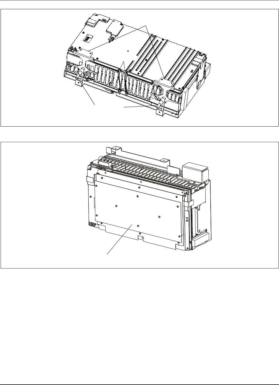
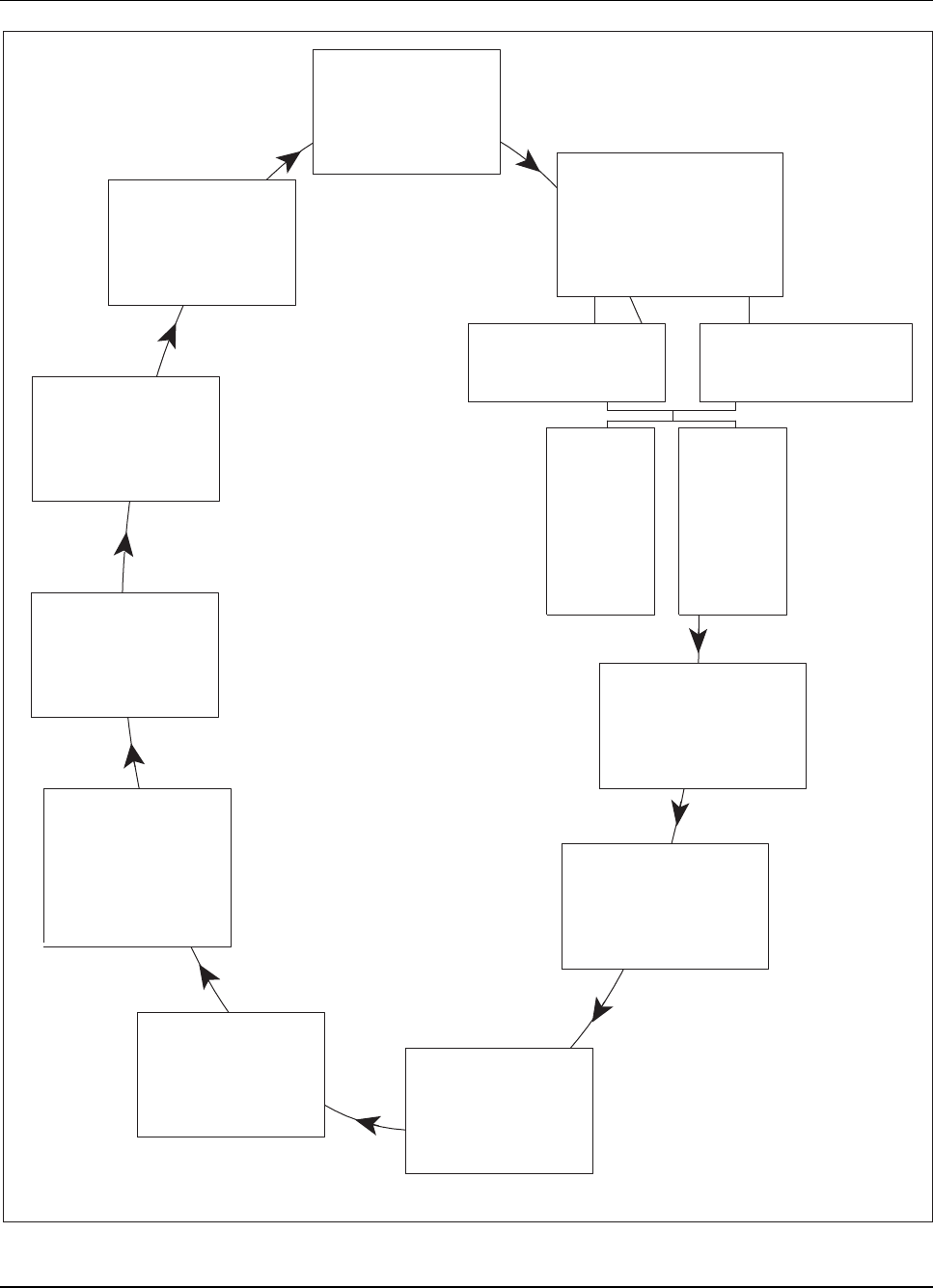
Figure 2-1. RBS 884 Pico (1900 MHz) Components
The RBS 884 Pico (1900 MHz) consists of a CRI that interfaces with remote
Radio Heads. The product is used for spot coverage in larger 1900 MHz
systems or for indoor wireless systems.
The RBS 884 Pico (1900 MHz) control hardware is installed in a standard
19-in equipment rack or an optional floor mount cabinet. The radio hardware
is installed on a wall or other vertical surface separate from the CRI hardware.
With leased T1/E1 connections between the CRI and Radio Heads, the CRI
can be centrally located and the Radio Heads can be installed in separate
buildings. With non-leased connections between the CRI and Radio Head,
the maximum cable loss between the Radio Head and the CRI is 30 dB. This
cable loss restriction allows the first Radio Head to be located 800 m to
1000 m from the CRI (as measured by cable length).
To comply with FCC RF exposure requirements, the external antennas used
with this device must be mounted to provide a minimum separation distance
of 20cm (8 inches) from all persons, with the antenna gain not exceeding 14
dBi. Amplifiers and boosters are not permitted.
2-4 1/1551-AE/LZB 119 3834 Uae Rev PA 2001-03-05

System Description
Control and Radio Interface (CRI) Hardware
•CRI subrack
–Signaling Terminal Regional (STR)
–DC/DC Power Converter (2)
–Exchange Terminal Board (ETB) (maximum 2)
–Enhanced Link Interface (ELI) (maximum 4)
–Extension Module Regional Processor (EMRP)
–EMRP with Device Speech Bus Access (EMRPS) (maximum
10)
–Radio Interface Time Switch (RITSW)
–Cabinet Identification (CID) Unit
–Fan Unit
–Sync (synchronization) cable
•Nonintegrated AC/DC Power Converter
Radio Hardware
•Radio Head
–Dual Transceiver (DTRX) (2)
–Radio Head Interface (RHI) unit with customer interface
–Power Supply Unit (PSU)
–Cascade Adapter Board (CAB) with Pulse Code Modulation
(PCM) interface ports
–External Duplexers (2)
•Antennas
–Monopole Antennas
–Patch Antenna Assembly (optional)
–External Antennas (optional)
The individual RBS 884 Pico (1900 MHz) equipment units are described in
Section 3.2 Equipment Unit Description on page 2-12.
1/1551-AE/LZB 119 3834 Uae Rev PA 2001-03-05 2-5

System Description
2.1 RBS 884 Pico Call Path and Signaling
2.1.1 Control Signaling
Control signaling for the RBS 884 Pico (1900 MHz) system is as follows:
•The MSC central processor sends the control signal to the Signaling
Terminal Central (STC) unit.
•The STC unit converts the signal format and sends the signal to the
Exchange Terminal Circuit (ETC).
•The ETC inserts the control signal into a time slot on the PCM
T1/E1 link to the base station CRI.
•The ETB extracts the control signal and sends it to the STR.
•The STR converts the information back to processor format and
outputs it on the Extension Module Regional Processor Bus
(EMRPB).
•The EMRPB connects the processing units (EMRP and EMRPSs).
–The EMRP controls the CRI hardware units, including the
RITSW, ETB, and ELI.
–The EMRPS (through the ELI) controls the TRXs in the Radio
Head. The T1/E1 network connection with Link Access
Protocol D (LAPD) provides error detection and retransmission.
2.1.2 Speech Signaling
Speech signaling for the RBS 884 Pico (1900 MHz) system is as follows:
•The Public Switched Telephone Network (PSTN) sends a speech or
data signal to the Group Switch (GS) at the MSC.
•A digital call is processed by the MSC as follows:
–Routed to the Transcoder Rate Adaptation Board (TRAB)
–Converted into compressed format used in the air interface with
Algebraic Code Excited Linear Prediction (ACELP)
2-6 1/1551-AE/LZB 119 3834 Uae Rev PA 2001-03-05

System Description
–Combined with two other voice paths that share the same
frequency
–Routed to the correct ETC
•The signal is sent over a T1/E1 line to the base station CRI where it
is routed to the following units:
–ETB
–RITSW
–ELI
•The ELI unit communicates with TRXs in the Radio Head through a
T1/E1 line.
•In the Radio Head, the RHI receives the signal and routes it to the
correct TRX, where it is converted to RF. The RF is then filtered and
coupled to the antenna(s) for transmission.
2.2 Synchronization
Synchronization is necessary to ensure a stable carrier frequency reference
and error-free transmission between the RBS and the MSC.
Jitter and wander introduced by the T1/E1 line between the CRI and the
Radio Head is filtered out by the Radio Head Phase Locked Loop (PLL). The
frequency accuracy of the Radio Head is better than 0.1 ppm at the presence
of maximum wander (138 UI), provided that the reference frequency for the
PLL is traceable to a long-term Stratum 2 clock reference from the network.
With non-leased or proprietary connections between the CRI and the Radio
Head, the ELI unit is connected to the incoming MSC PCM Stratum 2
reference. The T1/E1 connectionontheETBunitiscabledtothefirstELI
unit. The first ELI unit uses the PCM reference to provide the transmit clock
for the PCM interface to the Radio Heads. The reference from the first ELI
unit is passed to the other ELI units through the ETB-ELI Sync Cable.
3 Architecture
The RBS 884 Pico (1900 MHz) controls and handles communication
between the MSC and the mobile stations. The configuration of the Pico
equipment depends on the following:
1/1551-AE/LZB 119 3834 Uae Rev PA 2001-03-05 2-7

System Description
•Number of cells
•Number of voice channels in each cell
•Transmit power
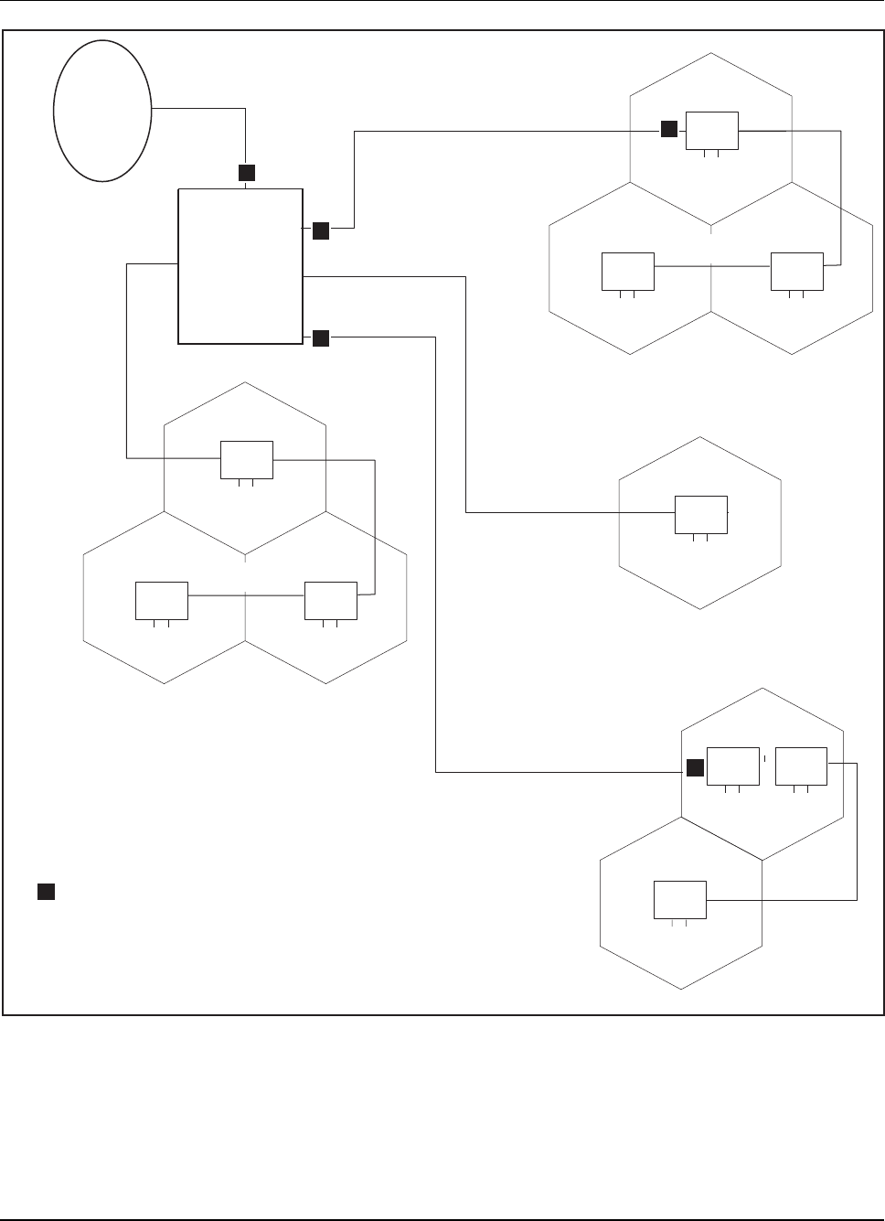
Figure 2-2 on page 2-9 shows the main connections to and from an RBS 884
Pico (1900 MHz).
2-8 1/1551-AE/LZB 119 3834 Uae Rev PA 2001-03-05
System Description
CRI
MSC
CRI Control and Radio Interface
MSC Mobile Switching Center
Radio
Head
Leased
T1/E1
Non-leased
T1/E1
Non-leased
T1/E1
Non-leased
T1/E1
T1 1.544 Mbps Transmission Link
E1 2.048 Mbps Transmission Link
Radio
Head
Radio
Head Radio
Head
Long Haul
T1/E1
Long Haul
T1/E1
Radio
Head
Radio
Head
Leased
T1/E1
Leased
T1/E1
Leased
T1/E1
Long Haul
T1/E1
Long Haul
T1/E1
Radio
Head
Radio
Head
Radio
Head Radio
Head
Long Haul
T1/E1
Long Haul
T1/E1
Channel Service Unit
c
c
c
c
c
c
Figure 2-2. General Overview of RBS 884 Pico (1900 MHz) Configuration
The GS at the MSC is responsible for switching calls between subscribers.
The calls can be between two mobile subscribers or between a mobile
subscriber and a subscriber in the public telephone network. The RBS
1/1551-AE/LZB 119 3834 Uae Rev PA 2001-03-05 2-9

System Description
contains several regional processors that are controlled by and work with the
central processor. The regional processors control the time switch and the
TRXs in the base station. The time switch in the base station makes sure that
the speech signals from the MSC are connected to the correct TRX. The
TRXs generate radio signals that are emitted by the base station antenna
to the mobile stations. The semipermanent connections are set up in the
MSC. Each TRX handles three digital speech channels, but uses only one
channel on the T1/E1 PCM link.
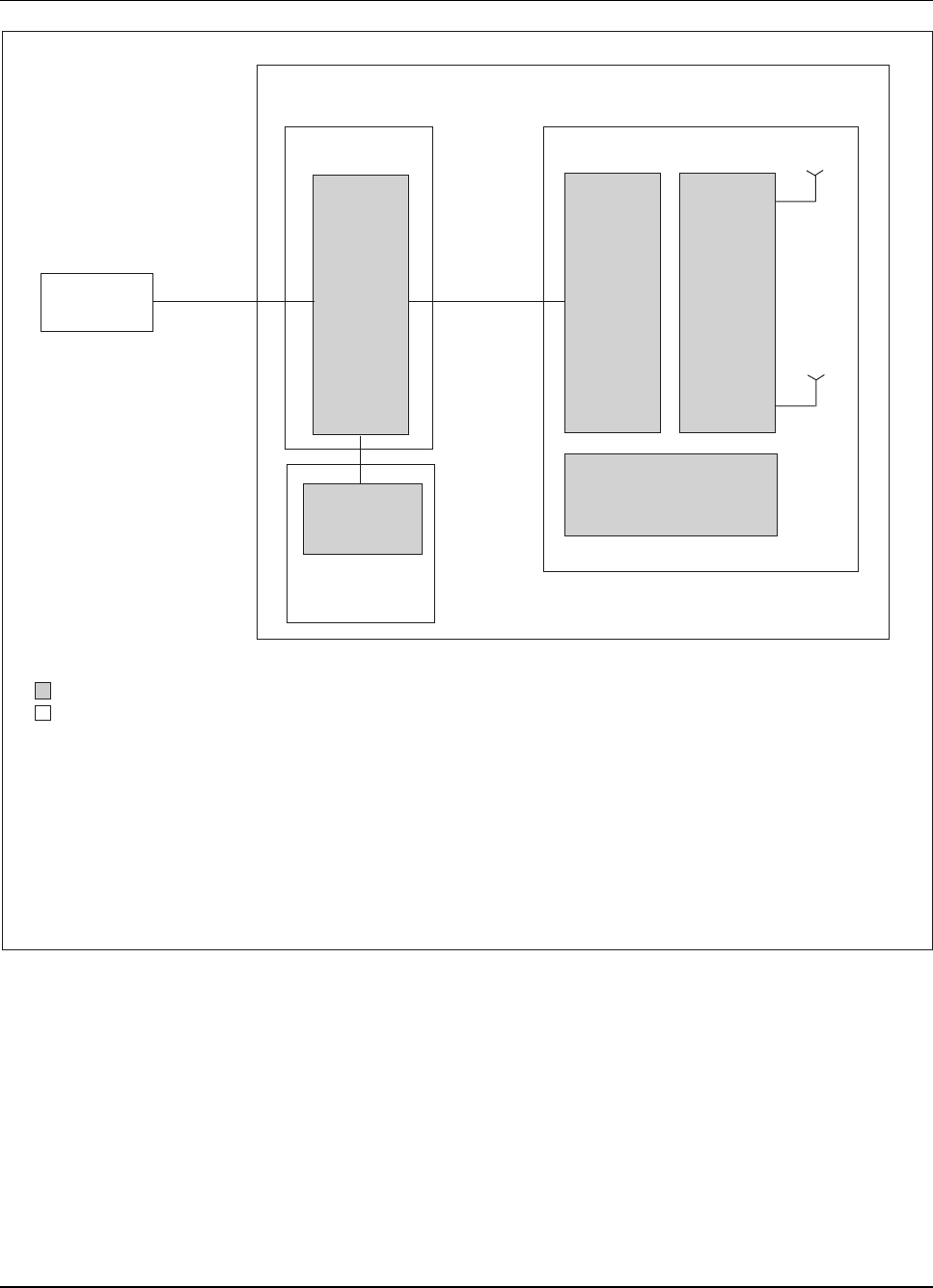
The RBS 884 Pico (1900 MHz) is an application of the Mobile Base Station
Subsystem (MBS) and follows the same general functional structure. The
basic functional and implementation structure is shown in Figure 2-3
on page 2-11.
2-10 1/1551-AE/LZB 119 3834 Uae Rev PA 2001-03-05
System Description
RBS 884 Pico (1900 MHz) Base Station
COP
SUP
CRI Radio Head
MOP ANP
SUP
TX/RX
TX/RX
MSC
Network
Connection Proprietary
or Leased
T1/E1 T1/E1
Modem Part
Mobile Switching Center
Power Supply Unit
Support Part
1.544 Mbps Transmission Link
Combined Transmit and Receive Antennas
Antenna Near Part
Control Part
Control and Radio Interface
2,048 Mbps Transmission Link
Functional Unit
Implementation Unit
MOP
MSC
PSU
SUP
T1
TX/RX
ANP
COP
CRI
E1
AC/DC
PSU
Fan Unit
Figure 2-3. RBS 884 Pico (1900 MHz) Functional and Implementation Units
3.1 Functional Unit Description
The following section provides a description of the RBS 884 Pico (1900
MHz) from the working or functional point of view.
1/1551-AE/LZB 119 3834 Uae Rev PA 2001-03-05 2-11

System Description
3.1.1 Control Part (COP)
The COP provides communication between the RBS hardware the MSC for
radio traffic control and statistical data gathering. The COP also provides
control for the Modem Part (MOP), Antenna Near Part (ANP), and the
Support Part (SUP). Other functions include network synchronization and
time switching. COP equipment is located in the CRI cabinet.
Each RBS 884 Picocell requires a control channel for its coverage area.
Movement between Picocells triggers the normal hand-off mechanisms in
the CMS 8800 system. The RBS 884 Pico (1900 MHz) also supports the
hand-off operations of the MS as the MS migrates between the outdoor
Microcell/Macrocell environment and the indoor Picocell environment.
3.1.2 Modem Part (MOP)
The MOP functional unit provides conversion from MS speech and control
channel data to and from radio waves to communicate with the MS. The
voice transcoder part of the MOP functionality resides in the MSC. In the
RBS 884 Pico (1900 MHz), the Carrier Frequency stabilization is performed
in the Radio Head.
3.1.3 Antenna Near Part (ANP)
The ANP functional unit includes combining and separating RF carriers for
transmitting and receiving on the same radio antennas. The RBS 884 Pico
(1900 MHz) ANP functionality is localized in the Radio Head hardware. The
Radio Head has a fixed antenna configuration and four carriers (two DTRX).
3.1.4 Support Part (SUP)
The SUP provides DC power and cooling to the hardware equipment units.
3.2 Equipment Unit Description
The hardware equipment units are divided into two units: control and radio.
The control equipment units consist of the CRI hardware used to implement
the COP and SUP functions. The CRI hardware includes the following
components:
•Nonintegrated power (AC/DC) converter
•DC/DC Power Converter(2)
2-12 1/1551-AE/LZB 119 3834 Uae Rev PA 2001-03-05

System Description
•Cabinet Identification (CID) Unit
•Fan Unit
•Signaling Terminal Regional (STR)
•Exchange Terminal Board (ETB) (2)
•Enhanced Link Interface (ELI) (maximum 4)
•Extension Module Regional Processor (EMRP)
•EMRP with Device Speech Bus Access (EMRPS) (maximum 10)
•Radio Interface Time Switch (RITSW)
The control equipment units are housed in a standard 19-in equipment
rack (or optional floor mount cabinet) that includes a Fan Unit to cool
the equipment.
The radio equipment units consist of the Radio Head hardware to implement
the MOP, ANP, and SUP functions and includes the following components:
•Integrated Power Supply
•Two DTRX (four TRX) units
•Radio Head Interface (RHI) unit
•Cascade Adapter Board (CAB) for T1/E1 connections
3.2.1 Control and Radio Interface (CRI) Subrack
The CRI subrack provides communication functions, APZ (control part
of Ericsson's telephone exchange system) regional processing, and static
(semipermanent) switching functions for the RBS 884 Pico (1900 MHz).
The CRI equipment consists of the following assemblies:
•standard CRI subrack and Fan Unit assembly
•external AC/DC power supply assembly
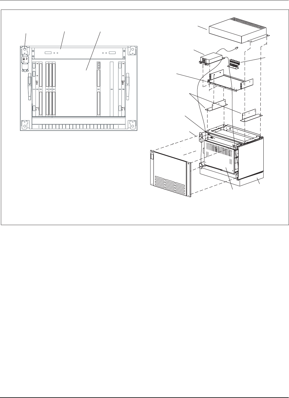
The CRI equipment is provided in a rack mount installation, shown in
Figure 2-4 on page 2-14and an optional floor mount installation shown in
Figure 2-5 on page 2-15.
1/1551-AE/LZB 119 3834 Uae Rev PA 2001-03-05 2-13
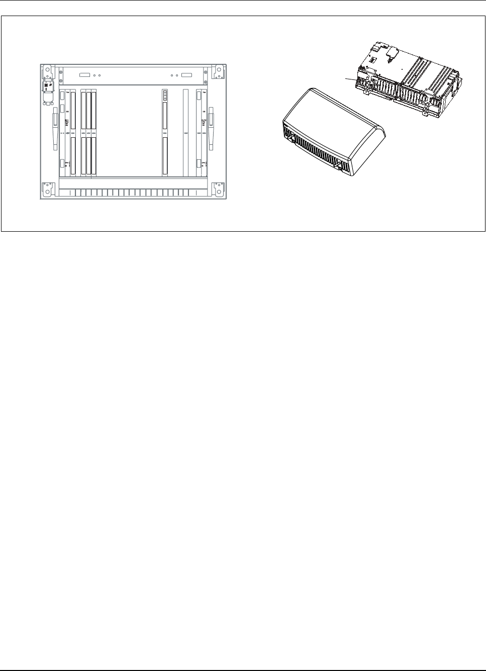
System Description
CID Unit
CRI Subrack
CRI Rack Mount
Fan Unit
Power Supply
Power Supply
Shelf
Rack/
Cabinet Rail
(EIA)
Air Duct
CID
CRI
EIA
Cabinet Identification
Control and Radio Interface
Electronic Industries Association
CID Unit
Fan Unit CRI Magazine
CRI Subrack
Patch Panel
ELIELI
18
ETB
6
ETB
541 17
EMRPS
16
EMRPS
15
EMRPS
14
EMRPS
13
EMRPS
12
EMRPS
11
EMRPS
10
EMRPS
9
EMRPS
8
EMRPS EMRP
719202322
ELI ELI DC/DC
RITSW
Figure 2-4. CRI Rack Mount Equipment
2-14 1/1551-AE/LZB 119 3834 Uae Rev PA 2001-03-05
System Description
CID Unit Fan Unit CRI Magazine
CRI Subrack
01 2
3
4
5
678910
11
12
13
14 15 AB C
D
E
Power
Error
DC/DC
1 ST
R
2
ETB
5 ETB
6
EMRPS
7
EMRPS
8
EMRPS
9
EMRPS
10
EMRPS
11
EMRPS
12
EMRPS
13
EMRPS
14
EMRPS
15
EMRPS
16
EMRPS
17
ELI EELILI
18
19 20
EMRP
4
DC/DC
23
CRI Floor Mount
Patch
Panel
Top Cover
Power Supply
Power Shelf
Base
CRI
Cabinet
CID Unit
Fan Unit
Side Brackets
CID Cabinet Identification
CRI Control and Radio Interface
Figure 2-5. CRI Floor Mount Equipment
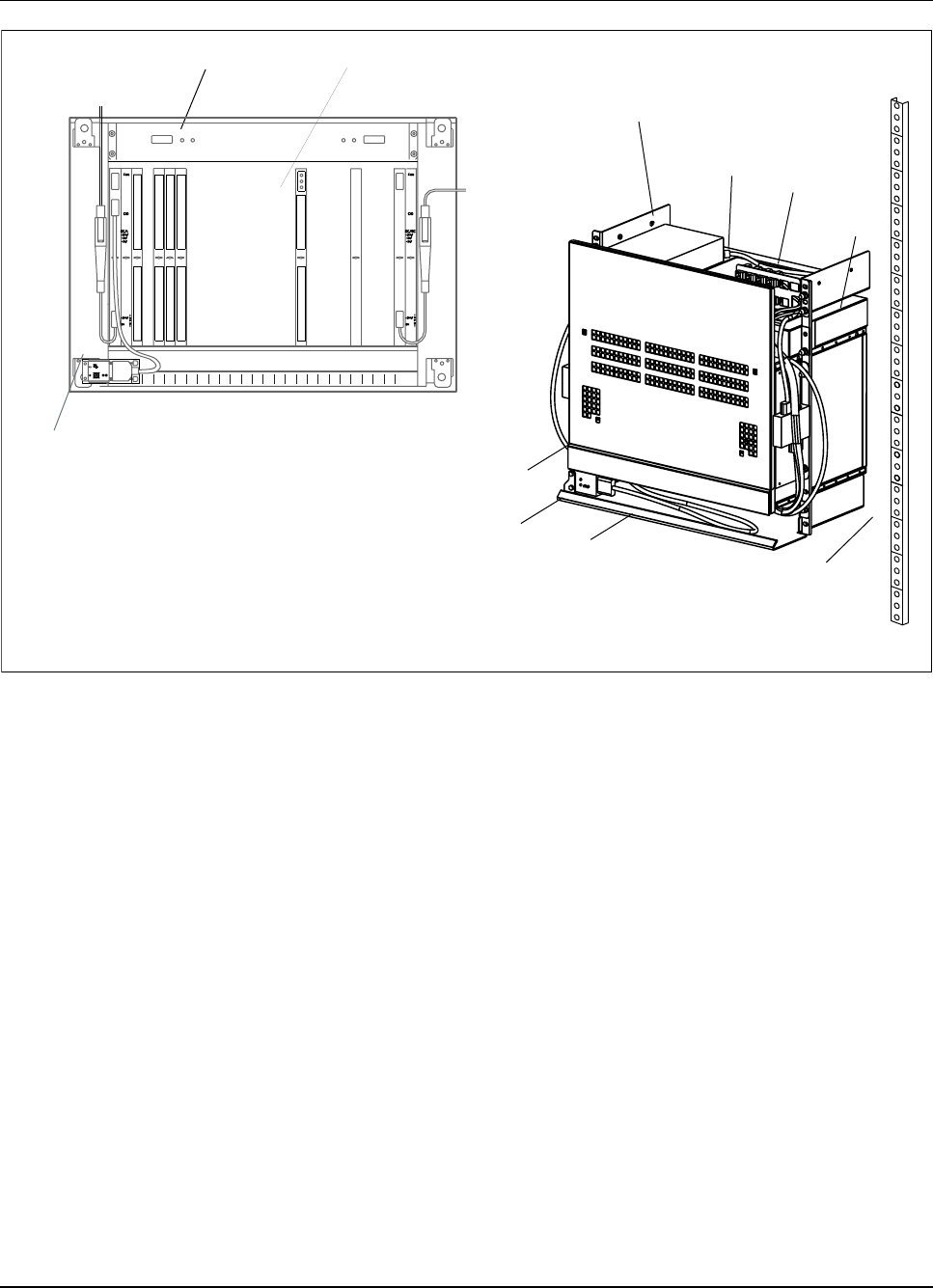
The CRI units are housed in a standard subrack (or optional floor
mount cabinet) that provides Electromagnetic Compatibility (EMC) and
Electromagnetic Interference (EMI) shielding, backplane interconnections,
and local power conditioning. Figure 2-6 on page 2-16 shows an example
of the CRI cabinet layout.
1/1551-AE/LZB 119 3834 Uae Rev PA 2001-03-05 2-15
System Description
AC/DC
CID
DC/DC
ELI
EMRP
EMRPS
ETB
RITSW
STR
Alternating Current to Direct Current
Cabinet Identification Unit
Direct Current to Direct Current
Enhanced Link Interface
Extension Module Regional Processor
EMRP with Device Speech Bus Access
Exchange Terminal Board
Radio Interface Time Switch
Signaling Terminal, Regional
Note: The CID Unit in this illustration is for the Floor Mount cabinet only. The CID Unit for the Rack Mount is
located on the bottom left side of the CRI subrack.
Fan Unit
DC
/
DC
S
T
R
E
M
R
P
DC
/
DC
E
T
B
E
T
B
E
M
R
P
S
R
I
T
S
W
E
L
I
E
M
R
P
S
E
M
R
P
S
E
M
R
P
S
E
M
R
P
S
E
M
R
P
S
E
M
R
P
S
E
M
R
P
S
E
M
R
P
S
E
M
R
P
S
E
L
I
1 2 4 5 6 7 8 9 10 11 12 13 14 15 16 17 18 19 20 22 23
AC/DC Power Supply Patch Panel
CID
Unit
DC
Filter
DC
Filter
E
L
I
E
L
I
Figure 2-6. CRI Floor Mount Cabinet Layout
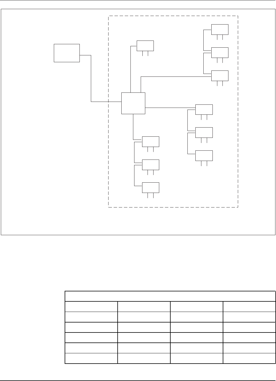
Figure 2-7 on page 2-17 shows interconnections of the CRI assemblies.
2-16 1/1551-AE/LZB 119 3834 Uae Rev PA 2001-03-05
System Description
DC/DC
DEVCB
DEVSB
E1
ELI
EMRP
EMRPS
ETB
RITSW
STR
T1
Direct Current to Direct Current
Device Control Bus
Device Speech Bus
2.048 Mbps Transmission Link
Enhanced Link Interface
Extension Module Regional Processor
EMRP with Device Speech Bus Access
Exchange Terminal Board
Radio Interface Time Switch
Signaling Terminal, Regional
1.544 Mbps Transmission Link
ETB
STR
ETB
T1/E1
EMRP RITSW
EMRP
Bus
DEVCB DEVSB
DC/DC
EMRPS
(maximum of 10)
(maximum of 4)
ELI
PCM
Connection
to Radio
Heads
Figure 2-7. CRI Interconnections
The following paragraphs describe the hardware units used in the RBS 884
Pico (1900 MHz) CRI magazine.
3.2.1.1 DC/DC Power Converter Units
The CRI has two DC/DC converter units that supply power to the CRI
subrack. The converter units receive power from a single +24 Vdc power
feed and convert it to ±5 Vdc for use by the CRI boards.
1/1551-AE/LZB 119 3834 Uae Rev PA 2001-03-05 2-17

System Description
Each DC/DC converter unit is capable of powering the entire CRI subrack in
case of failure of one of the units. When both units are operational, they
share the load. The EMRPSs have onboard DC/DC converters.
3.2.1.2 Exchange Terminal Board (ETB)
The ETB unit provides a T1/E1 network interface to the MSC. It is available
in a 24 time slot T1 version (ETB24) or a 32 time slot E1 version (ETB32).
The physical T1/E1 interface is a quarter-plug connector on the front
panel of the ETB. The unit provides frame synchronization and time slot
extraction/generation of the T1/E1 signal.
The ETB routes the speech DS0 signals to the RITSW overtheCRI
backplane. The ETB extracts base station control information from a single
T1/E1 time slot. This signal is routed to the STR. The ETB also extracts the
8 kHz frame clock from the network interface link. The frame clock provides
the Carrier Frequency Reference (CFR) to the RITSW.
3.2.1.3 Signaling Terminal Regional (STR)
The STR is a protocol converter that communicates with the STC in the
MSC. Communication with the MSC is through a single DS0 time slot
on the MSC-CRI span. This time slot is routed from the span to the STR
by way of the ETB. In addition, the STR generates the EMRPB interface
within the CRI.
3.2.1.4 Extension Module Regional Processor (EMRP)
The EMRP is controlled by the MSC. In turn, the EMRP controls the ETB,
ELI, and RITSW through the backplane Device Control Bus (DEVCB). The
EMRP communicates to the MSC through the EMRPB provided by the STR.
The EMRP executes regional software downloads from the MSC.
3.2.1.5 EMRP with Speech Bus Access (EMRPS)
The EMRPS is an EMRP with extended processor power and a speech bus
interface. The EMRPS implements the logical parts of the radio channel
functions for the RBS 884 Pico (1900 MHz). The EMRPS executes software
downloads from the MSC.
The EMRPS unit communicates with the MSC through the EMRPB
interface. Communication with the Radio Heads is through the RITSW
and ELI units by way of the DEVSB interface in the CRI backplane. The
EMRPS unit is equipped with an onboard DC/DC converter that derives the
required internal voltages from the CRI backplane.
2-18 1/1551-AE/LZB 119 3834 Uae Rev PA 2001-03-05
System Description
3.2.1.6 Enhanced Link Interface (ELI)
The ELI is used to provide a T1/E1 connection between the CRI and the
Radio Head. The device supports a single, 100-ohm twisted-pair 1.544
Mbit/s long-haul or short-haul T1 interface, or a single, 120-ohm twisted
pair or 75-ohm coaxial 2.048 Mbit/s long-haul or short-haul E1 interface.
The ELI unit contains switches to select the link type (T1/E1 leased or
non-leased), short-haul T1 line build-up, long-haul attenuation and the
75-ohm coaxial E1 cable grounding.
The ELI maps the DEVSB time slots from the RITSW to the T1/E1 time
slots using a predefined multiplexing and mapping scheme. The ELI also
handles the LAPD-based retransmission protocol at the CRI end of the
connection. On the Radio Head end, the RHI unit handles all time slot
mapping and retransmission functionality
The T1 interface utilizes Extended Superframe (ESF) framing format and
Bipolar with 8 Zero Substitution (B8ZS) line code. The E1 interface utilizes
Frame Alignment Signal-Cyclic Redundancy Check (FAS-CRC) framing
format and High Density Bipolar Level 3 (HDB3) line code.
A Light Emitting Diode (LED) lamp on the ELI indicates the status of the
T1/E1 line. The ELI transmits the T1/E1 alarms back to the Radio Head
corresponding to the quality of the signal received on the T1/E1 line from the
Radio Head. The ELI can be monitored and controlled by the EMRP through
the backplane DEVCB with Digital Path (DIP) supervision.
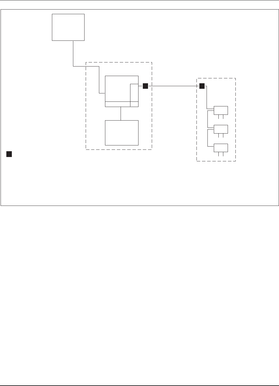
See Figure 2-8 on page 2-19 for an illustration of ELI unit and Radio
Head connections.
MSC Radio
Head 1 Radio
Head 2 Radio
Head 3
E
L
I
CRI T1/E1 T1/E1
Long Haul T1/E1
Long Haul
T1/E1
Leased LineLeased Line
c c c
cChannel Service Unit
CRI Control and Radio Interface
MSC Mobile Switching Center
Figure 2-8. ELI Unit with Cascaded Radio Heads
1/1551-AE/LZB 119 3834 Uae Rev PA 2001-03-05 2-19

System Description
3.2.1.7 Radio Interface Time Switch (RITSW)
The RITSW is a local space/time switch in the CRI that routes DS0 time
slots between ETB, EMRPS and ELI. The RITSW also provides the clock
synchronization and stabilization in the CRI.
The RITSW is controlled by the EMRP through the backplane DEVCB.
The DEVCB interface to RITSW is used to set the semi-permanent DS0
time-slot connections.
3.2.1.8 Fan Unit
The Fan Unit is a physically separate part of the CRI subrack and is mounted
directly above the subrack. The Fan Unit contains two fans that are powered
by the DC/DC converters in the subrack. The fans are rated such that a single
fan can provide sufficient cooling of the CRI.
3.2.1.9 Cabinet Identification (CID) Unit
The CID Unit is located on the top-left side of the CRI floor mount version
and on the bottom-left side of the CRI rack mount version. The CID Unit
allows a unique identification number to be set for the CRI cabinet during
installation. This number is read at the MSC to identify the cabinet for
alarm reporting and fault resolution.
3.2.1.10 Internal Alarm Distribution
The CRI distributes and reports the following equipment related alarms:
•Fan alarm
•DC/DC converter alarm
The alarms are distributed in the CRI as shown in Figure 2-9 on page 2-21.
2-20 1/1551-AE/LZB 119 3834 Uae Rev PA 2001-03-05
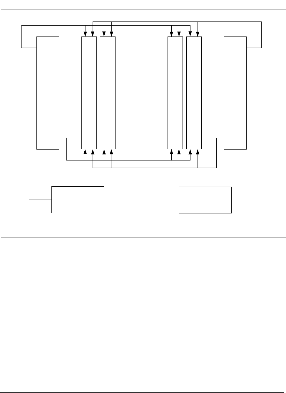
System Description
DC/DC Alarm
DC/DC DC/DC
DC/DC Alarm
Fan
Alarm Fan #1
Fan
Alarm
Fan #2
. . .
. . .
. . .
E
M
R
P
S
E
M
R
P
S
E
M
R
P
S
E
M
R
P
S
DC/DC
EMRPS Direct Current to Direct Current
Extension Module Regional Processor with Device Speech Bus Access
Figure 2-9. CRI Internal Alarm Distribution
3.2.2 External AC/DC Power Supply Unit (PSU)
The external AC/DC PSU is housed in a 19 in rack-mountable assembly. The
PSU draws power from the building 110 (50-60 Hz) or 220 Vac (50-60 Hz)
power receptacle, and supplies +24 Vdc (nominal) through the DC filter
units to the DC/DC converters in the CRI cabinet.
Note: The external AD/DC power unit does not have an ON/OFF
switch. The only means for switching the PSU on/off is by
plugging and unplugging it from the building power receptacle.
The CRI should be installed within easy access of the building
power receptacle.
1/1551-AE/LZB 119 3834 Uae Rev PA 2001-03-05 2-21
System Description
3.2.3 Radio Head
The Radio Head implements the MOP functionality and part of the ANP
and SUP functionalities. The Radio Head is located in a custom enclosure.
RF shielding minimizes coupling of signals into and from the RF circuitry
and allows compliance to EMI and EMC specifications. The Radio Head
contains two DTRX units for a total of four TRXs in each Radio Head.
The Radio Head is mounted on a pre-mounted support bracket that is
installed on a wall, column, pole, or other vertical surface. Modular RJ-45
connectors, mounted on the top of the Radio Head, provide connections for
the primary and secondary PCM link cables.
The Radio Head has its own internal power supply that must be connected to
the standard mains power through the AC power plug connector.
RBS 884 Pico (1900 MHz) Radio Head uses two Transmit/Receive (TX/RX)
antennas. The Radio Head antennas can be either monopole, patch, or
external antennas.
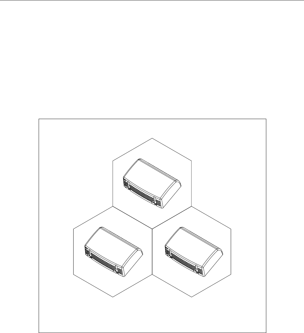
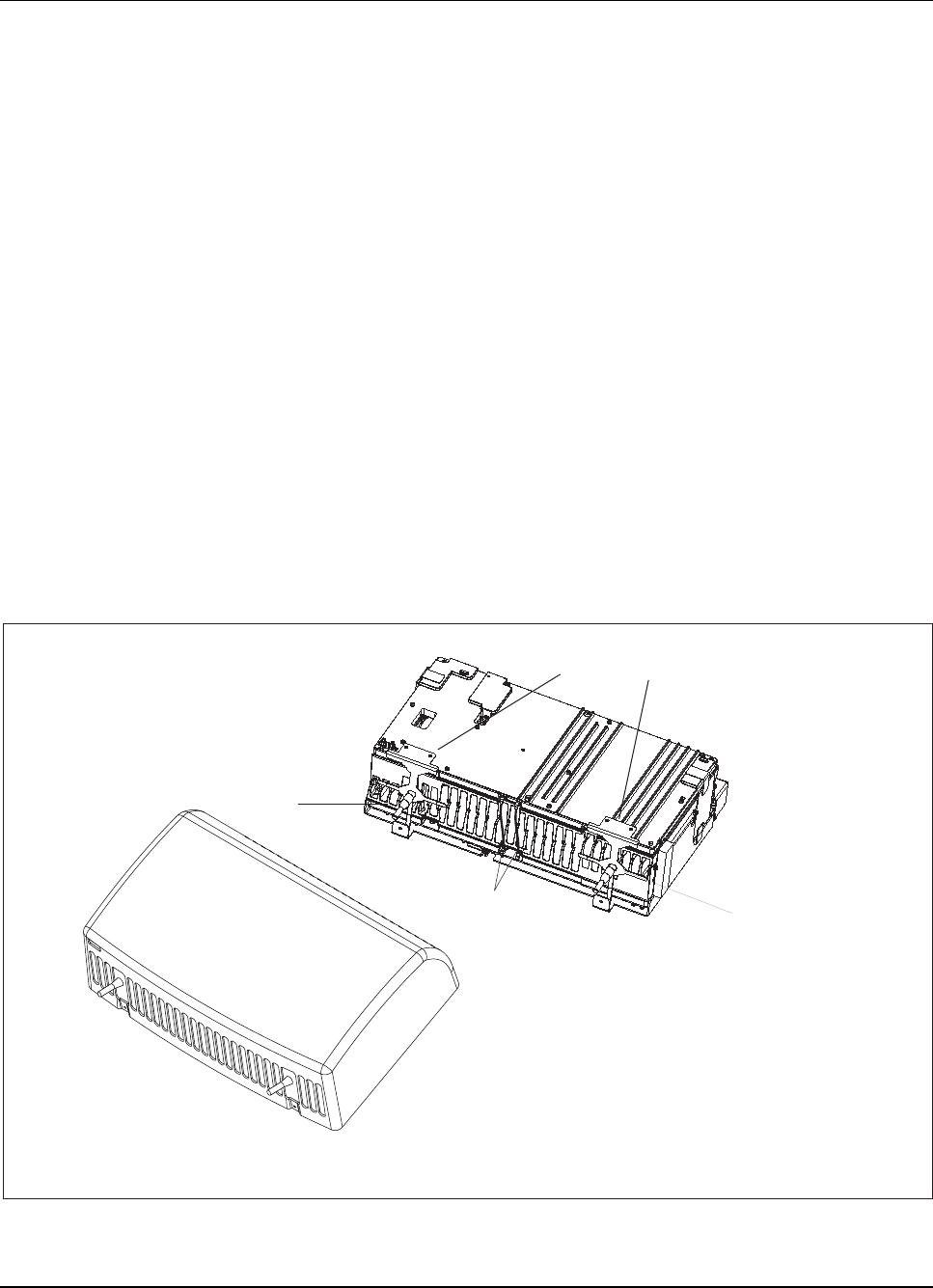
See Figure 2-10 on page 2-22 for an illustration of the Radio Head with
monopole antennas. See Figure 2-11 on page 2-23 for a Radio Head block
diagram.
Radio Head
DTRX Dual Transceiver
(with Cover)
Radio Head
(without Cover)
Coax Cable
DTRX to DTRX
Antenna Bracket Assembly
Monopole Antenna
Monopole Antenna
Figure 2-10. Radio Head with Monopole Antennas
2-22 1/1551-AE/LZB 119 3834 Uae Rev PA 2001-03-05
System Description
RHI
TRX2
TRX1
Duplexer
Σ
Dual TRX
Board
TLINK
B
Antenna
A
Antenna
Tx/Rx
Tx/Rx
TRX4
TRX3
Duplexer
Σ
Dual TRX
Board
TLINK
TLINK
TLINK
TX and
RX LO
TX and
RX LO
C
A
B
Secondary T1/E1
to next RH
Power
Supply
AC Power
DC Power
AC Line
Filter
Front DTRX
Back DTRX
CRI Control and Radio Interface
DTRX Dual TRX
LO Local Oscillators
RX Receive
RH Radio Head
RHI Radio Head Interface
TLINK Transistor-Transistor Logic Link
TRX Radio Transceiver
TX Transmit
ΣCombiner
CAB Cascade Adapter Board
Primary T1/E1 to CRI or
Primary T1/E1
to previous RH
Figure 2-11. Radio Head Block Diagram
3.2.3.1 Dual Transceiver (DTRX) Unit
Each DTRX unit has the functionality of two 1900 MHz TRXs and produces
100 mW (nominal) per carrier (TRX) at the Radio Head antenna port. Each
1/1551-AE/LZB 119 3834 Uae Rev PA 2001-03-05 2-23

System Description
TRX performs frequency upconversion and downconversion in two stages
with both TRXs using the same TX and RX Intermediate Frequency (IF). A
single Local Oscillator (LO) is shared between the TRXs.
3.2.3.2 Radio Head Interface (RHI)
The RHI unit is located under the Radio Head chassis and provides the
following interfaces:
•Primary T1/E1 interface to the CRI or to the previous Radio Head
•Secondary T1/E1 interface to the next Radio Head
•TLINK connection to the TRXs
•Customer interface with alphanumeric display
•Carrier frequency stabilization
•Local device processor
The RHI software is loaded in the factory. Upgrades to the RHI software can
be made by downloading new software through the ELI unit.
3.2.3.3 Antennas
The Radio Head contains two integrated TX and RX monopole antennas,
as shown in Figure 2-12 on page 2-25. The monopole antennas provide an
omnidirectional pattern. An optional dual patch antenna assembly that
mounts on the Radio Head provides a directional pattern with gain.
Note: The monopole RF connectors can be used for two external
antennas. External antennas are not provided with the RBS 884
Pico (1900 MHz) system. See RF Module EN/LZN 724 0010 for
RF engineering guidelines.
2-24 1/1551-AE/LZB 119 3834 Uae Rev PA 2001-03-05
System Description
Monopole
Antennas
Coax Cable
Monopole Antenna Bracket Assembly
Note: The duplexer cables are not shown.
Figure 2-12. Radio Head Monopole Antennas
Dual Patch Antenna
Figure 2-13. Radio Head Dual PatchAntenna
3.2.3.4 Radio Head User Interface
The Radio Head user interface is visible through an opening in the Radio
Head chassis. The eight-character alphanumeric display and push buttons
allow the user to configure the following parameters:
1/1551-AE/LZB 119 3834 Uae Rev PA 2001-03-05 2-25

System Description
•Primary PCM link operations mode
–T1 (long-haul, short-haul, line build-out/attenuation)
–E1 (long-haul, short-haul)
•Secondary PCM link operations mode
–T1 (long-haul, short-haul, line build-out/attenuation)
–E1 (long-haul, short-haul)
•Cabinet ID
•Alarms
–Primary PCM link
–Secondary PCM link
–TRX
•Hardware Unit (Board) Status
–TRX status
–Software revision and hardware information
–PLL status
–Error logs for use by the local Ericsson Repair Service Center
See Figure 2-14 on page 2-27 for the location of the Radio Head user
interface. See Part 4, Radio Head Installation,andPart 6, Troubleshooting
for a detailed description of the user interface and recommended fault
resolutions.
2-26 1/1551-AE/LZB 119 3834 Uae Rev PA 2001-03-05
System Description
2 HAUL
PRI_IF (Primary Interface)
SEC_IF (Secondary Interface)
PRI_IF
PrSH Primary Short Haul
SeLH Primary Long Haul SeSH Secondary Short Haul
SeLH Secondary Long Haul
PrSH
SeSH PrLH
SeLH
<35m
<65m
<95m
<125
<155
<185
<210
0dB
-7dB
-15dB
-22dB
SEC_IF
1 LINK
T1
E1
3 NTWK (Network)
ATT (AT&T spec. 138 UI)
BELL (Bellcore spec. 28 UI)
4 CASCAD (Cascade)
ENDY (End of cascade)
ENDN (Not end of cascade)
6 ERRORS
For Test Use Only 5 CABID
Cabinet Identifier
8 SAVE
Save settings to
nonvolatile memory
EXIT
Exit Configuration Menu
9 BOOT
Reboot Radio Head
Exit Configuration Menu
7 INFO
SWINFO
HW_GEN
PRODUC
HW_REV
TIM
DAC
Not all menu items may be present
due to parameter dependencies.
11
Link T1 only
1
Figure 2-14. Radio Head User Interface
1/1551-AE/LZB 119 3834 Uae Rev PA 2001-03-05 2-27

System Description
4 Equipment Configurations
The RBS 884 Pico (1900 MHz) Radio Heads can be connected to CRI
equipment through non-leased (proprietary) or leased T1/E1 links. Within the
RBS 884 Pico (1900 MHz) system, Radio Heads can be separately located in
individual cells or colocated within a single cell. Both arrangements allow
for cascade connections of up to three Radio Heads with a single proprietary
or leased link and up to ten Radio Heads with four links. Refer to Figure 2-2
on page 2-9. The maximum cable loss between Radio Heads is 30 dB.
The maximum cell radius for all cell types is approximately30to50m(98
to 164 ft) or an approximate area of 2,826 to 7,854 sq m (30,170 to 84,500
sq ft), depending on the propagation conditions.
RefertoFigure2-15onpage2-29,Figure2-16onpage2
-30,and Figure
2-17 on page 2-31 for examples of possible configurations.
Note: Each system implementation is unique and may not be
completely represented in this manual. Detailed configuration
information is provided in Part 5 Configuration and Test.
2-28 1/1551-AE/LZB 119 3834 Uae Rev PA 2001-03-05
System Description
RH
RH
RH
RH
RH
RH
RH
RH
Pico
CRI
MSC
Link Group 1
Link Group 2
Link Group 4
Link Group 3
Leased T1/E1
Leased T1/E1
Leased T1/E1
T1/E1
Non-
Leased
Non-
Leased
Non-
Leased Non-
Leased
Non-
Leased
Leased
CRI Control and Radio Interface
MSC Mobile Switching Center
RH Radio Head
RH
RH
Non-
Leased
Channel Service Unit
c
c
c
c
c
c
c
c
c
Figure 2-15. RBS 884 Pico (1900 MHz) with Leased Connections, Example
1/1551-AE/LZB 119 3834 Uae Rev PA 2001-03-05 2-29
System Description
RH
RH
RH
RH
RH
RH
RH
RH
Pico
CRI
MSC
Location 1
Location 2
Location 3
Leased T1/E1
Leased T1/E1
Leased T1/E1
T1/E1
Non-
Leased Non-
Leased
Non-
Leased
Non-
Leased
Non-
Leased
Leased T1/E1
CRI Control and Radio Interface
MSC Mobile Switching Center
RH Radio Head
RH
RH
Location 4
Non-
Leased
Channel Service Unit
c
c
c
c
c
cc
c
c
Link Group 4
Link Group 3
Link Group 2
Link Group 1
Figure 2-16. RBS 884 Pico (1900 MHz) CRI at the MSC, Example
2-30 1/1551-AE/LZB 119 3834 Uae Rev PA 2001-03-05
System Description
RH
RH
RH
RH
RH
RH
PICO
CRI
RH
RH
RH
MSC
CRI Control and Radio Interface
MSC Mobile Switching Center
RH Radio Head
Leased T1/E1
Non-
Leased
Non-
Leased
Non-
Leased
Non-
Leased
Non-
Leased
Non-
Leased
Non-
Leased
Non-
Leased
Non-
Leased
RH
Non-
Leased
Link Group 4
Link Group 3
Link Group 2
Link Group 1
Figure 2-17. RBS 884 Pico (1900 MHz) with Non-Leased Connections, Example
Refer to Table 2-1 on page 2-31 for a list of the other Radio Head placement
options. Each cascade location requires one T1/E1 link (proprietary or
non-proprietary) from the CRI cabinet.
Table 2-1. RBS 884 Pico (1900 MHz) Radio Head Placement Options
Maximum Number of Radio Heads
Group 1 Group 2 Group 3 Group 4
3 3 3 1
3 3 1 3
3 1 3 3
1 3 3 3
3 3 2 2
1/1551-AE/LZB 119 3834 Uae Rev PA 2001-03-05 2-31

System Description
Table 2-1. RBS 884 Pico (1900 MHz) Radio Head Placement Options (Continued)
Maximum Number of Radio Heads
Group 1 Group 2 Group 3 Group 4
3 2 2 3
3 2 3 2
2 2 3 3
2 3 2 3
2 3 3 2
The RBS 884 Pico (1900 MHz) CRI is delivered partially assembled with
the following CRI units:
•DC/DC Converters (2)
•ETB24 or ETB32 (2)
•STR
•EMRP
•ELI (1)
•RITSW
The EMRPS unit and address plugs are shipped with the Radio Head Kit.
One EMRPS unit is required for each Radio Head.
4.1 Macro/Pico Information
The RBS 884 Pico (1900 MHz) can be colocated with an RBS 884 Macro
(1900 MHz) by installing a Pico ELI unit in the Macro CRI (position 17, 18,
19, or 20). Additional EMRPS units can be ordered for use with the Pico
Radio Heads. If the Radio Heads are not connected through leased lines,
an ETB-ELI Sync Cable is available to ensure a stable carrier frequency
reference for the DTRXs. See Figure 2-18 on page 2-33.
2-32 1/1551-AE/LZB 119 3834 Uae Rev PA 2001-03-05
System Description
RH
RH
RH
Building
Macro Site
MSC
Leased T1/E1
Leased T1/E1
Macro
CRI
TCB
E
L
I
R T T
CLINK
CLINK Control Link
CRI Control and Radio Interface
ELI Enhanced Link Interface
MSC Mobile Switching Center
RH Radio Head
RTT Radio Transceiver Terminal
TCB Transceiver Cabinet
Channel Service Unit
c
c c
Figure 2-18. Macro Site with Pico ELI and Radio Heads
5 Technical Data
5.1 Capacity
The capacity of an RBS 884 Pico (1900 MHz) system depends on whether
separate or colocated Radio Heads are used. The available number of
digital voice channels for different configurations is described in Table
2-2 on page 2-34.
1/1551-AE/LZB 119 3834 Uae Rev PA 2001-03-05 2-33

System Description
Table 2-2. RBS 884 Pico (1900 MHz) Capacity
Number of Voice
Channels
Configuration Number of
Transceivers
Number
of Control
Channels without
MVER
with
MVER
Separate Radio
Heads
1to10
4to40 1to10 11 to 110 8to80
Colocated Radio
Heads
2to10
8to40 123 to 119 20 to 116
Note: Mobile Verification Channel (MVER)
5.2 Technical Specifications
General technical specifications for the RBS 884 Pico (1900 MHz) are
shown in Table 2-3 on page 2-34 and Table 2-4 on page 2-38.
Table 2-3. RBS 884 Pico (1900 MHz) Technical Specifications
Description Specification
Number of
transceivers (TRX)
40 (maximum)
4 per Radio Head
Number of carriers 4 per Radio Head
Transmitting Characteristics
Transmitting
frequency band
1930 –1990 MHz
Maximum power
into antenna
connector
100 mW (20 dBm) per carrier
Note: Two carriers are attached to each antenna connector.
Channel spacing 120 KHz
Receiving Characteristics
Receiving
frequency band
1850 –1910 MHz
Minimal receive
channel spacing
in one cell
120 KHz
2-34 1/1551-AE/LZB 119 3834 Uae Rev PA 2001-03-05

System Description
Table 2-3. RBS 884 Pico (1900 MHz) Technical Specifications (Continued)
Description Specification
Receiver sensitivity
(fading, with
diversity, 3% BER)
0km/h
8km/h
-105 dBm
-98 dBm
Note: The RBS 884 Pico (1900 MHz) is downlink limited due to the
low output power (100 mW or 20 dBm) from the Radio Head.
The link is balanced when the MS output power is 25 dBm
(half the maximum power).
Demodulation,
digital mode
Type pi/4 - DQPSK
Symbol rate 24.3 ksymbol/s
Data rate 48.6 kbit/s
Traffic channels for
each carrier
3
Dimensions and Weight
CRI Cabinet
dimensions
Width 482 mm (19 in) rack mount
597 mm (23.5 in) floor mount)
Height 480 mm (18.9 in) rack mount
483 mm (19 in) floor mount)
Depth 290 mm (11.4 in) rack mount
400 mm (15.8 in) (floor mount)
Weight (fully
equipped)
35 kg (77 lb)
Radio Head
dimensions (with
cover)
Width 480 mm (18.9 in)
Height 320 mm (12.6 in)
Depth 180 mm (7.1 in)
Weight 18 kg (39.7 lb) includes mounting brackets, cover,
and monopole antennas
PCM Connection (T1)
PCM Connection
ANSI T1.403-1989
Bit rate 1.544 Mbit/s
PCM Connection
ANSI T1.403-1989
Board connector RPV 301 302/1 (CRI)
RJ-45 (RH)
Electrical
characteristics
TR-NWT-000499
1/1551-AE/LZB 119 3834 Uae Rev PA 2001-03-05 2-35

System Description
Table 2-3. RBS 884 Pico (1900 MHz) Technical Specifications (Continued)
Description Specification
T1 Format MSC-CRI SuperFrame (SF) or Extended SuperFrame (ESF)
Alternate Mark Inversion (AMI) or B8ZS line code
Note: Bit robbed signaling is not used.
CRI-RH and RH-RH ESF
B8ZS line code
Note: Bit robbed signaling is not used.
PCM Connection (E1)
PCM Connection
CCITT E1
Bit rate 2.048 Mbit/s
Board connector RPV 301 302/1 (CRI)
RJ-45 (RH)
Electrical
characteristics
G.703
E1 Format MSC-CRI FAS with or without CRC
HDB3 line code
Note: Bit robbed signaling is not used.
CRI-RH and RH-RH FAS with CRC
HDB3 line code
Note: Bit robbed signaling is not used.
Additional PCM Parameters
Synchronization Traceable to a Stratum 2 reference
Maximum cable
length between
cascaded Radio
Heads
800 m to 1000 m with maximum attenuation of 30 dB using high quality cable
MSC-CRI 0–210 m (0 –685 ft)Line Build
Out (LBO)
compensation
for short-haul
connection to CSU
CRI-RH and RH-RH 0–210 m (0 –685 ft)
Long-haul
attenuation
CRI-RH and RH-RH 0dbB
7.5 dB
15 dB
22.5 dB
Minimum receive
level
CRI-RH and RH-RH -30 dB (T1/E1)
2-36 1/1551-AE/LZB 119 3834 Uae Rev PA 2001-03-05

System Description
Table 2-3. RBS 884 Pico (1900 MHz) Technical Specifications (Continued)
Description Specification
Power Supply
AC supply voltage Building supplied
voltage for CRI and
Radio Head
100 –240 Vac, 50 –60 Hz
AC/DC supply
voltage
CRI +24 Vdc ± 0.6 V, 300 W (maximum)
Power
consumption, Units
(maximum)
Radio Head 110 Vac 2 A
220 Vac 1 A
Environment
Climatic conditions Temperature: -40 Cto+70C
(transport and
storage)
Relative humidity 5–95%
Absolute humidity 1–50 g/m³
Climatic conditions Temperature:
(normal operation) CRI
Radio Head
5Cto40C
5Cto45C
Relative humidity 5–85%
Absolute humidity 2–26 g/m³
Mechanical
conditions
Sinusoidal vibration 10 m/s²at 5 –150 Hz
(transport and
storage)
Random vibration,
Accelerated
Spectral Density
(ASD)
1m²/s³at 5 –150 Hz
Mechanical shock 2400 m/s²(6 ms duration pulse)
Mechanical
conditions
Sinusoidal vibration 2m/s²at 5 –150 Hz
(normal operation) Random vibration
(ASD)
0.5 m²/s³at 5 –150 Hz
Seismic exposure
(safe function)
35 s at 1 –15 Hz (According to IEC 68-2-57 fig 3)
1/1551-AE/LZB 119 3834 Uae Rev PA 2001-03-05 2-37

System Description
Table 2-4. RBS 884 Pico (1900 MHz) Certification Specifications
Certification Specification
TIA/EIA Telecommunications
Industry Association
and Electronics
Industry Association
TIA/EIA-138
CSA Canadian Standards
Association
CSA 22.2 950-95
CRI: Canada ICES-003
Radio Head: Canada RSS-133
EN European
Committee for
Electrotechnical
Standardisation
EN 60950
FCC Federal
Communications
Commission
CRI: FCC Part 15 (Class A Rating)
Radio Head: FCC Part 15 (Class B Rating) and FCC Part 24
IEC International
Electrotechnical
Commission
IEC 60 950 2nd Edition
IEC 60 215 3rd Edition
NRTL Nationally
Recognized Testing
Laboratory (includes
Underwriters
Laboratory (UL) and
Electrical Testing
Laboratories (ETL)
and CSA
UL 1950 3rd Edition
Electromagnetic Compatibility (EMC) Emissions
FCC Federal
Communications
Commission
Unintentional Emissions: FCC Part 15
CISPR International Special
CommitteeonRadio
Interference
CISPR-22
ICES Interference-Causing
Equipment Standard
ICES 003
2-38 1/1551-AE/LZB 119 3834 Uae Rev PA 2001-03-05

System Description
Table 2-4. RBS 884 Pico (1900 MHz) Certification Specifications (Continued)
Certification Specification
EMC Immunity
IEC International
Electrotechnical
Commission
Radio frequency field: IEC 61000–4–3
Fast Transient Common Mode: IEC 61000–4–4
Magnetic Radiated: IEC 61000–4–8
Voltage Dips and Interrruptions: IEC 61000–4–11
1/1551-AE/LZB 119 3834 Uae Rev PA 2001-03-05 2-39

System Description
2-40 1/1551-AE/LZB 119 3834 Uae Rev PA 2001-03-05

Part 3
RBS 884 Pico (1900 MHz) CRI Installation
1 Introduction . . . . . . . . . . . . . . . . . . 3-3
2 SafetyPrecautions ............... 3-3
2.1 VoltageHazards ............. 3-3
2.2 Radio Frequency Radiation . . . . . . . . 3-4
2.3 Beryllium Oxide . . . . . . . . . . . . . 3-4
2.4 HeavyLoads ............... 3-5
3 ElectrostaticDischarge ............. 3-5
3.1 StorageandTransport .......... 3-5
3.2 ESDWristStrap ............. 3-6
4 GeneralInformation ............... 3-6
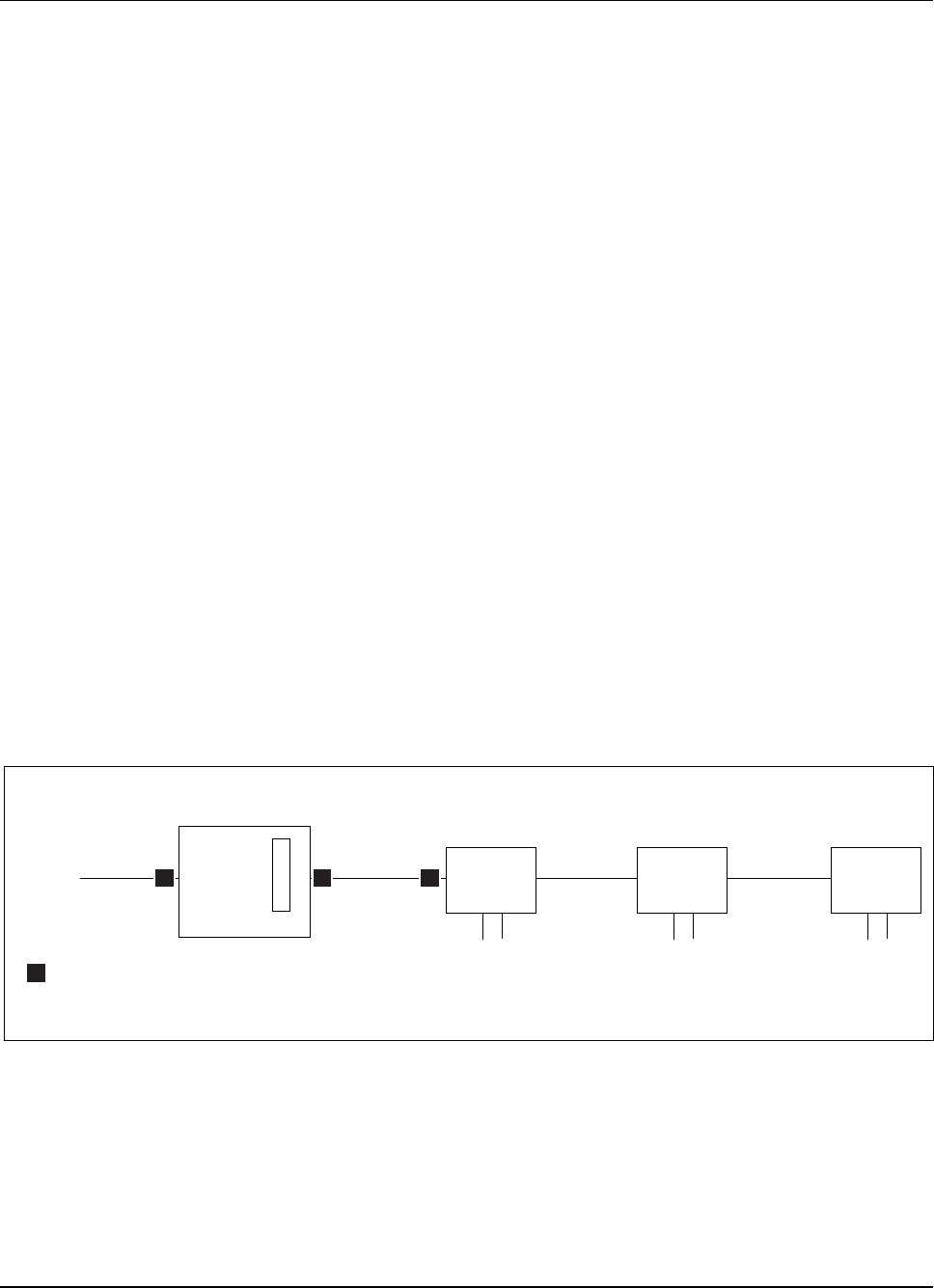
4.1 BasicCRISubrack ............ 3-6
4.2 OrderofInstallation ............ 3-7
4.3 CableInformation ............. 3-7
5 Unpacking ................... 3-9
5.1 Tools .................. 3-9
5.2 Inventory ................. 3-10
5.3 Unpacking CRI Equipment . . . . . . . . 3-10
6 SitePreparation ................. 3-11
6.1 Operating Environment . . . . . . . . . . 3-12
6.2 PowerRequirements ........... 3-12
6.3 T1/E1Requirements ........... 3-12
7 PrerequisitesandTools ............. 3-13
7.1 Materials ................. 3-13
7.2 CablesandNetwork ........... 3-13
7.3 Transmission Equipment . . . . . . . . . 3-14
7.4 Tools .................. 3-14
8 CabinetInstallationProcedures ......... 3-15
8.1 Installing the CRI Rack Mount . . . . . . . 3-15
8.2 Installing CRI Floor Mount . . . . . . . . . 3-18
8.3 Installing a Pico CRI Cabinet with Existing
MacroCabinets ............. 3-41
9 CRIHardwareUnitsandSwitches ........ 3-50
9.1 SettingETBSwitches ........... 3-50
9.2 Installing ELI Unit and Setting Switches . . 3-52
1/1531-AE/LZB 119 3834 Uae Rev PA6 2001-04-04 3-1

RBS 884 Pico (1900 MHz) CRI Installation
9.3 Installing EMRPS Units and Address Plugs . 3-57
10 Equipment Cabling and Start-up . . . . . . . . 3-62
10.1 CablingtheCRIHardware ......... 3-63
10.2 Defining Data Translations . . . . . . . . 3-80
10.3 EquipmentStart-up ............ 3-81
10.4 Completing CRI Installation . . . . . . . . 3-85
3-2 1/1531-AE/LZB 119 3834 Uae Rev PA6 2001-04-04

RBS 884 Pico (1900 MHz) CRI Installation
1 Introduction
This document contains step-by-step procedures for installing and cabling
the Control and Radio Interface (CRI) for the RBS 884 Pico (1900 MHz)
System. Additional information is also provided for adding RBS 884 Pico
functionality to an existing RBS 884 Macro (1900 MHz) CRI unit.
Note: The Radio Head installation procedures for the RBS 884 Pico
(1900 MHz) are described in Part 4, RBS 884 Pico (1900 MHz)
Radio Head Installation.
2 Safety Precautions
Before starting any installation, test, or maintenance procedures, review the
safety regulations provided in this section and any other applicable parts
of this manual. Additionally, the installer is responsible for determining
that the installation conforms to all applicable electrical, mechanical,
communications, and construction codes.
Carefully review each procedure before starting, including the
admonishments (dangers, warnings, and cautions) that are applicable to
the procedure.
2.1 Voltage Hazards
DANGER!
Hazardous voltages over 100V are used in the operation of this equipment.
Use extreme caution when working on energized equipment. Contact with
AC power of any voltage can cause injury and sometimes death.
Always observe the following:
•Shut off the power supply, if possible, before working on the
equipment.
•Remove all jewelry before working on the equipment.
1/1531-AE/LZB 119 3834 Uae Rev PA6 2001-04-04 3-3

RBS 884 Pico (1900 MHz) CRI Installation
•Do not touch high voltage connections when installing or operating
the equipment.
•If possible, keep one hand away from the equipment to reduce the
possibility of current flowing through vital body organs.
2.2 Radio Frequency Radiation
Warning!
Radio frequency from an antenna may be a danger to health, causing severe
burns to skin and clothing.
Notify the MSC to switch off the transmitters if you work with or near
antennas.
2.3 Beryllium Oxide
Some equipment contains beryllium oxide in ceramic form.
Warning!
Beryllium oxide is poisonous and constitutes a health hazard if present in
finely dispersed form, such as dust or smoke, which can be inhaled. Read
local hazardous chemical regulations before working with beryllium oxide.
Units with components containing beryllium oxide are marked with a
warning label. For detailed information about properties, health and
environmental hazards, refer to the regulations issued by the local authorities.
The following rules must be obeyed by all persons handling beryllium oxide:
•Ceramics containing beryllium oxide must not be scraped, filed,
ground, treated with acid, or machined in any other way.
•Compressed air must not be used to clean units containing beryllium
oxide.
•Always wear protective gloves when handling beryllium oxide.
•Use wet rags to collect dust and particles from damaged beryllium
oxide components. After use, place the rags in plastic bags and
seal the bags completely.
3-4 1/1531-AE/LZB 119 3834 Uae Rev PA6 2001-04-04

RBS 884 Pico (1900 MHz) CRI Installation
Scrapped beryllium oxide must be treated as environmentally hazardous
waste. Local authorities enforce regulations regarding the treatment and
disposal of environmentally hazardous waste. Investigate the applicable
local regulations and comply with them.
2.4 Heavy Loads
Warning!
A heavy load (anything over 10 kg (22 lb) lifted incorrectly can cause injury
to persons and damage to the equipment. A factory-shipped RBS 884 Pico
CRI cabinet weighs approximately 30 kg (66 lb).
3 Electrostatic Discharge
The human body acquires static charge in all situations involving movement.
The same effect is achieved when handling ordinary plastic materials.
If the body comes into contact with a grounded Integrated Circuit (IC)
component, this static charge may cause an Electrostatic Discharge (ESD)
resulting in a spark and damage to the component.
Note: To avoid component damage because of ESD, always follow
the instructions for handling sensitive electronic components
and circuit boards. Personnel must always use ESD protection
equipment when working with such components and circuit
boards.
3.1 Storage and Transport
Store and transport components and hardware units in their original
packaging.
Alternatively, use a conductive material or special IC carrier that either
short-circuits all contacts and pins or insulates them from external contact.
1/1531-AE/LZB 119 3834 Uae Rev PA6 2001-04-04 3-5
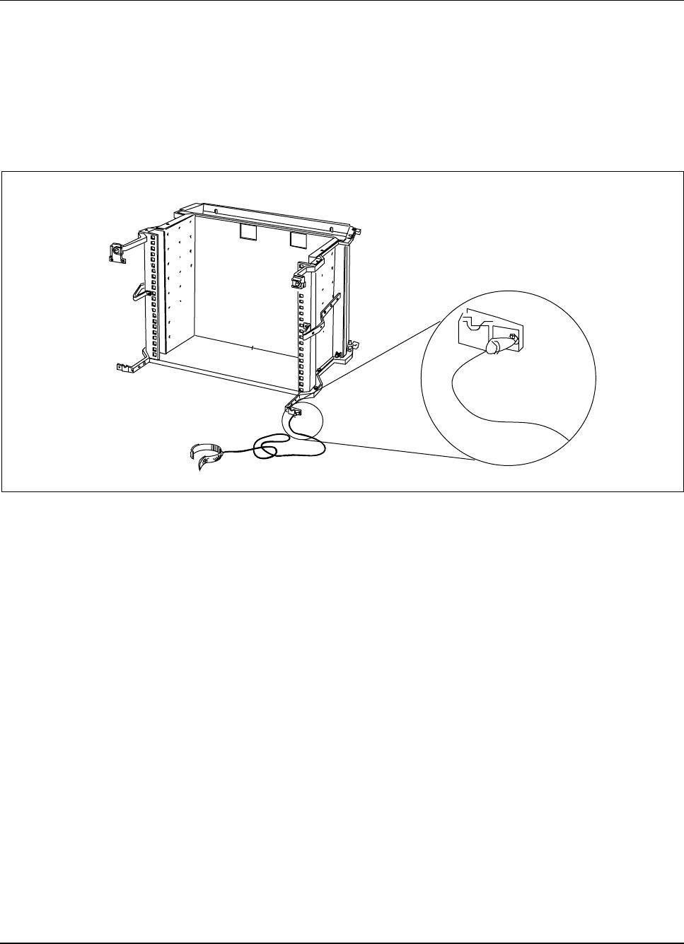
RBS 884 Pico (1900 MHz) CRI Installation
3.2 ESD Wrist Strap
When working with circuit boards, wear an ESD wrist strap to avoid ESD
damage to the boards. The strap can be connected to the collection bar
located in every cabinet shelf, as shown in Figure 3-1 on page 3-6.
Follow local procedures on testing the wrist strap.
Figure 3-1. ESD Wrist Strap and Cable Connected to the Cabinet
4 General Information
4.1 Basic CRI Subrack
The basic RBS 884 Pico (1900 MHz) CRI subrack arrives on site with
the following units pre-installed:
•DC/DC Converter Units (2)
•Signaling Terminal Regional (STR) Unit (1)
•Extension Module Regional Processor (EMRP) Unit (1)
•Exchange Terminal Board (ETB24/ETB32) Units (2)
3-6 1/1531-AE/LZB 119 3834 Uae Rev PA6 2001-04-04
RBS 884 Pico (1900 MHz) CRI Installation
•Enhanced Link Interface (ELI) Unit (1)
•Radio Interface Time Switch (RITSW) Unit
The EMRP with Speech Bus Access (EMRPS) units and additional ELI units
are packaged in separate shipping boxes and are installed based on the
number of Radio Heads in the system.
4.2 Order of Installation
If possible, perform the procedures in the order they are presented in the
manual.
4.3 Cable Information
The RBS 884 Pico (1900 MHz) internal cabling is partially installed at the
factory. The EMRPS, ETB, and ELI cables are installed by the customer
at the base station site. Refer to Section 7.2 on page 3-13 for information
about the specifications for the external cables.
4.3.1 Cable Labels
Cables are labeled at both ends to facilitate connection and troubleshooting.
An example of a typical label is shown in Figure 3-2 on page 3-7.
Board or unit name
Connector position
Female connector
Upper half of board
Slot number
EMRPS
EMRPS
Connection point at this
end of the cable
Connection point at the other
end of the cable
13A * 3F
14A * 3F
Upper side
of label
Lower side
folded under
cable tag
Figure 3-2. Typical Cable Label
4.3.2 Cable Connectors
RBS 884 Pico (1900 MHz) CRI hardware units (boards) accommodate
multiple connectors of different sizes. The designation of the connector
positions is shown in Figure 3-3 on page 3-8.
1/1531-AE/LZB 119 3834 Uae Rev PA6 2001-04-04 3-7
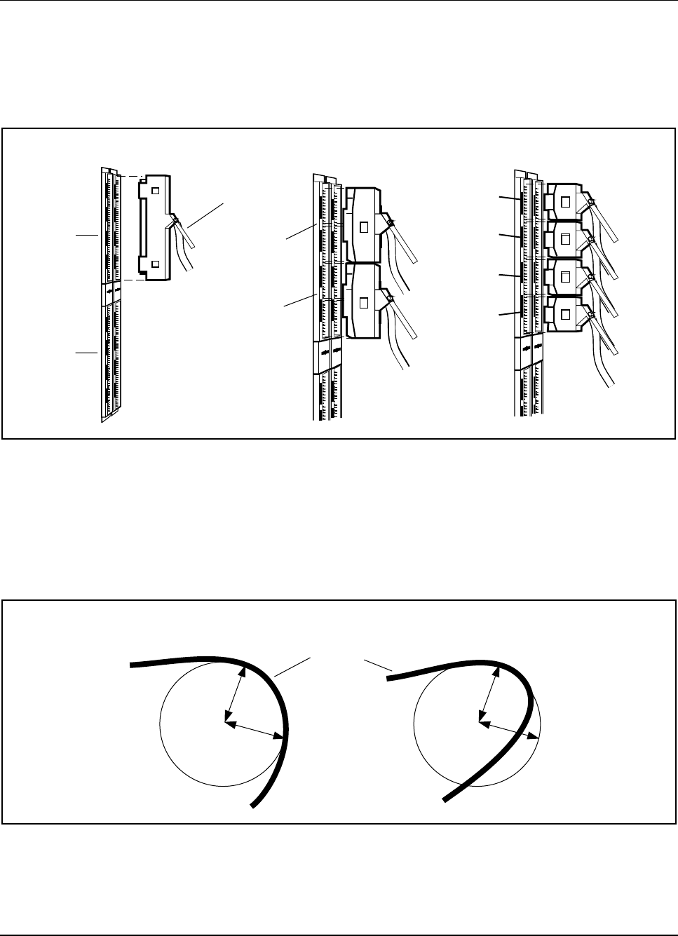
RBS 884 Pico (1900 MHz) CRI Installation
A reference to a cable position in the cabinet contains the slot position and
the connector position. For example, 15A3 refers to the unit in slot 15
and connector position A3. The connectors in the top half of the subrack
are designated as “A”and those in the bottom half as “B”(see Figure 3-3
on page 3-8).
A
B
A1
A2
A3
A4
Cable label
A1+A2
A3+A4
Full plug Half plug Quarter plug
Figure 3-3. Hardware Unit Connections
4.3.3 Bending Radius
Do not make any sharp bends in the transmission cables. Do not let the
bending radius be less then 10 times the diameter of the cable. See Figure
3-4onpage3-8.
Minimum
bending
radius
+Minimum
bending
radius
+
Acceptable Not acceptable
(too sharp bend)
RF cable
Figure 3-4. Minimum Bending Radius
3-8 1/1531-AE/LZB 119 3834 Uae Rev PA6 2001-04-04
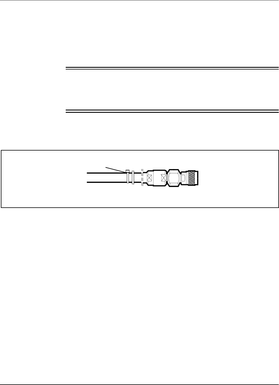
RBS 884 Pico (1900 MHz) CRI Installation
4.3.4 Coaxial Connectors
Push the coaxial connectors firmly in place. Tighten the connectors, first by
hand, then with a torque wrench set to the torque specified in this manual.
Use of the proper torque settings prevents damage to the connectors and
ensures optimal connection.
Caution !
Coaxial connectors are especially sensitive after tightening. Do not try to
change direction of the outgoing cable after tightening. Do not use the
outgoing cable as a tool to tighten the connector.
Note: The N-connectors (with a cross-hatched ring) shown inFigure
3-5 on page 3-9 can be sufficiently tightened by hand and, thus,
do not require a torque wrench.
Figure 3-5. Example of an N-Connector (Can also be Angled)
5 Unpacking
The RBS 884 Pico (1900 MHz) is delivered to the site in one or more boxes
or transportation crates. Inside the boxes or crates, the equipment is packed
in plastic bags or cardboard boxes.
5.1 Tools
A pair of cutters (side-cutting pliers, for example) is recommended for
cutting the transport straps, and a knife is recommended for cutting the
boxes and bags.
1/1531-AE/LZB 119 3834 Uae Rev PA6 2001-04-04 3-9

RBS 884 Pico (1900 MHz) CRI Installation
5.2 Inventory
Complete the following instructions before starting the installation:
1. If a box or crate is damaged, inspect the equipment immediately after
unpacking. If the equipment appears to be damaged, follow your
local procedures or contact the local support office.
2. Check the delivered hardware against the Shipping List.
3. Inventory all items.
4. After the equipment has been removed, the boxes or crates can be
disposed of according to local regulations.
5.3 Unpacking CRI Equipment
The CRI rack mount equipment is delivered in either one box or one
transportation crate. The CRI floor mount equipment is delivered in two or
more boxes or crates. The EMRPS Kit is shipped in a separate box according
to the number of Radio Heads ordered.
5.3.1 Unpacking Boxes
If the CRI equipment and EMRPS kit are delivered in boxes, unpack and
dispose of the boxes according to local procedures.
Note: For RBS 884 Pico (1900 MHz) system orders, one EMRPS Kit
is shipped with every Radio Head Kit. The EMRPS unit and
address plugs are installed in the CRI cabinet. Do not transfer
theEMRPSKittotheRadioHeadsite.
5.3.2 Unpacking Transportation Crates
If the equipment is delivered in transportation crates, use the following
instructions:
1. Cut the transport straps around the packing crate. Unlock the locking
clips for the lid.
2. See Figure 3-6 on page 3-11 for an illustration of the CRI
transportation crate.
3. Lift off the lid.
4. Remove the four corner packing pieces.
5. Unlock the locking clips from the bottom of the crate.
3-10 1/1531-AE/LZB 119 3834 Uae Rev PA6 2001-04-04
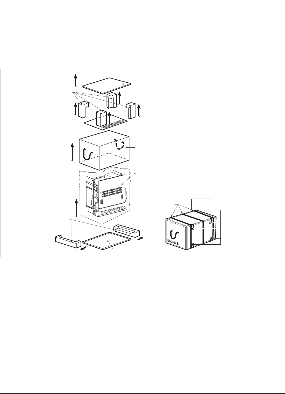
RBS 884 Pico (1900 MHz) CRI Installation
6. Lift the frame clear of the equipment.
7. Remove the accessories from the packing bag.
8. Remove the equipment from the packing bag.
9. Dispose of the packing material and crate components according to
local regulations.
Corner
Packing
End
Packing
Lid
Door
Frame
Bag Strap
Bottom of the Crate
CRI Equipment
11 x 8
Locking
Clips
Figure 3-6. Unpacking Transportation Crate
6 Site Preparation
Specific site preparation guidelines for the RBS Pico (1900 MHz) CRI are
provided in this section. Verify that the operating environment and power
requirements in this section have been met before starting the installation.
1/1531-AE/LZB 119 3834 Uae Rev PA6 2001-04-04 3-11

RBS 884 Pico (1900 MHz) CRI Installation
6.1 Operating Environment
The CRI is designed to operate in an indoor, temperature-controlled
environment. The installation site must comply with the following
environmental requirements:
•The air is free of dust, smoke, and debris.
•The walls, ceiling, and floor are completed.
•Ambient temperature is 5 Cto40C with 5 to 85% humidity.
6.2 Power Requirements
The CRI power supply converts the following AC power sources to +24 Vdc
for use in the CRI:
•110 Vac, 50/60 Hz
•220 Vac, 50/60 Hz
Note: Select or install, if necessary, a 110/220 Vac power outlet within
1 to 1.5 m (3 to 5 ft) of the CRI. The power outlet serves as the
safety power-disconnect point for the CRI power supply.
6.3 T1/E1 Requirements
The T1/E1 connection requirements are as follows:
•MSC Connection
–T1: 1.544 Mbit/s
–E1: 2.048 Mbit/s
•Delay: 5 ms maximum
•Clock: Stratum 2 or better
3-12 1/1531-AE/LZB 119 3834 Uae Rev PA6 2001-04-04

RBS 884 Pico (1900 MHz) CRI Installation
7 Prerequisites and Tools
7.1 Materials
This section describes the hardware prerequisites for the installation of the
RBS 884 Pico (1900 MHz) CRI.
Determine if the following equipment and supplies are available prior to
starting the CRI installation.
7.1.1 Rack Hardware
A suitable 19-in equipment rack with 11 consecutive rack units is available.
Sufficient space to install and maintain the equipment is provided.
7.1.2 Floor Mounting Hardware
All appropriate bolts, washers, and mounting accessories are available
for securing the base to the floor. The mounting hardware is not included
with the CRI.
7.2 Cables and Network
7.2.1 Transmission Cables
All transmission cables are available, and meet the following
requirements:
•T1 –100-ohm plenum rated, Category 5 (CAT 5), 24-gauge
unshielded, twisted-pair (UTP) cable
•E1 –120-ohm plenum rated, CAT 5, 24-gauge individually shielded,
twisted-pair cable
•E1 –75-ohm dual coaxial cable
The use of high quality cable with a maximum attenuation of 30 dB allows a
separation of 800 to 1000 m between Radio Heads based on cable length.
7.2.2 T1/E1 Network Lines
All T1/E1 network lines are available and meet the requirements of Section
6.3 on page 3-12, regardless of medium.
1/1531-AE/LZB 119 3834 Uae Rev PA6 2001-04-04 3-13

RBS 884 Pico (1900 MHz) CRI Installation
7.3 Transmission Equipment
7.3.1 Impedance Matching Network
A 75 to 120-ohm Impedance Matching Network is available for E1
75-ohm coaxial cable. The Impedance Matching Network converts the
impedance of coaxial cable so that its signal can run on twisted-pair wiring.
Further information about the Impedance Matching Network and E1 cable
installation is provided in Part 4 RBS 884 Pico (1900 MHz) Radio Head
Installation.
7.3.2 Channel Service Unit (CSU)
An adequate number of Channel Service Units (CSU) are available. The
CSUs are required to receive or transmit signals to and from the PSTN.
For a proprietary configuration, CSUs are installed between the MSC and the
CRI. For a leased-line configuration, CSUs are installed between the MSC
and the CRI and between the CRI and the first Radio Head in each T1/E1 link.
7.4 Tools
The following tools are available to install the RBS 884 Pico (1900
MHz) CRI:
•ESD wrist strap
•Extractor tool for removing cards (handle and button)
•Cable connector torque wrench set including:
–Torque wrench (preset to 0.6 Nm and2.8Nm)
–Torx bit TX10 and TX8 for circuit board screws
–Subminiature Connector Type A (SMA) tool for coaxial cables
•Flat-blade screwdriver set for power and data cable connectors
•Phillips screwdriver set
•Torx screwdrivers TX20 and TX30
•T1 or E1 test set with cables
•8-position crimping hand tool
•RJ-45 connectors
3-14 1/1531-AE/LZB 119 3834 Uae Rev PA6 2001-04-04

RBS 884 Pico (1900 MHz) CRI Installation
•Side-cutting pliers
•Metric socket set with 100 mm and 300 mm extension bars
•Torque wrench with socket adapter
•Small soldering iron
•Multimeter (voltmeter and ohmmeter)
•Electric light
•Cable ties and cable tie gun
•Extra ESD bag
8 Cabinet Installation Procedures
This section describes the procedures for installing the RBS 884 Pico
CRI unit.
The Pico CRI unit is available in the following configurations:
•Rack mount (standard product) for installation in a 19-in equipment
rack
•Floor mount (optional product) for installation on a cabinet base as a
single configuration or for installation with existing Macro cabinets
Pico cells can also be added to a Macro system by installing a Pico ELI unit
in the RBS 884 Macro CRI magazine (see Step 3 on page 3-53).
8.1 Installing the CRI Rack Mount
Preparation
1.
Warning!
The partially-equipped Pico CRI weighs approximately 30 kg (66 lb).
Ericsson recommends that two persons are present during the
installation.
1/1531-AE/LZB 119 3834 Uae Rev PA6 2001-04-04 3-15

RBS 884 Pico (1900 MHz) CRI Installation
Verify that all materials have been received and inventoried as
described in Section 5 on page 3-9.
Note: A standard 19-in equipment rack holds three RBS
884 Pico (1900 MHz) CRI cabinets.
2. Complete all site preparation according to Section 6 on page 3-11.
Note: Wall supports must not be used in earthquake areas.
Install CRI Subrack
3. Position the 19-in equipment rack and anchor it to the floor and to
the cable ladder.
4. Install the assembled CRI subrack (BFE 401 89/1 or 89/2) in the 19-in
rack, using eight screws (four screws on each side) to mount the
CRI to the rack rail. See Figure 3-7 on page 3-17 for an illustration
of the CRI rack mount subrack.
3-16 1/1531-AE/LZB 119 3834 Uae Rev PA6 2001-04-04
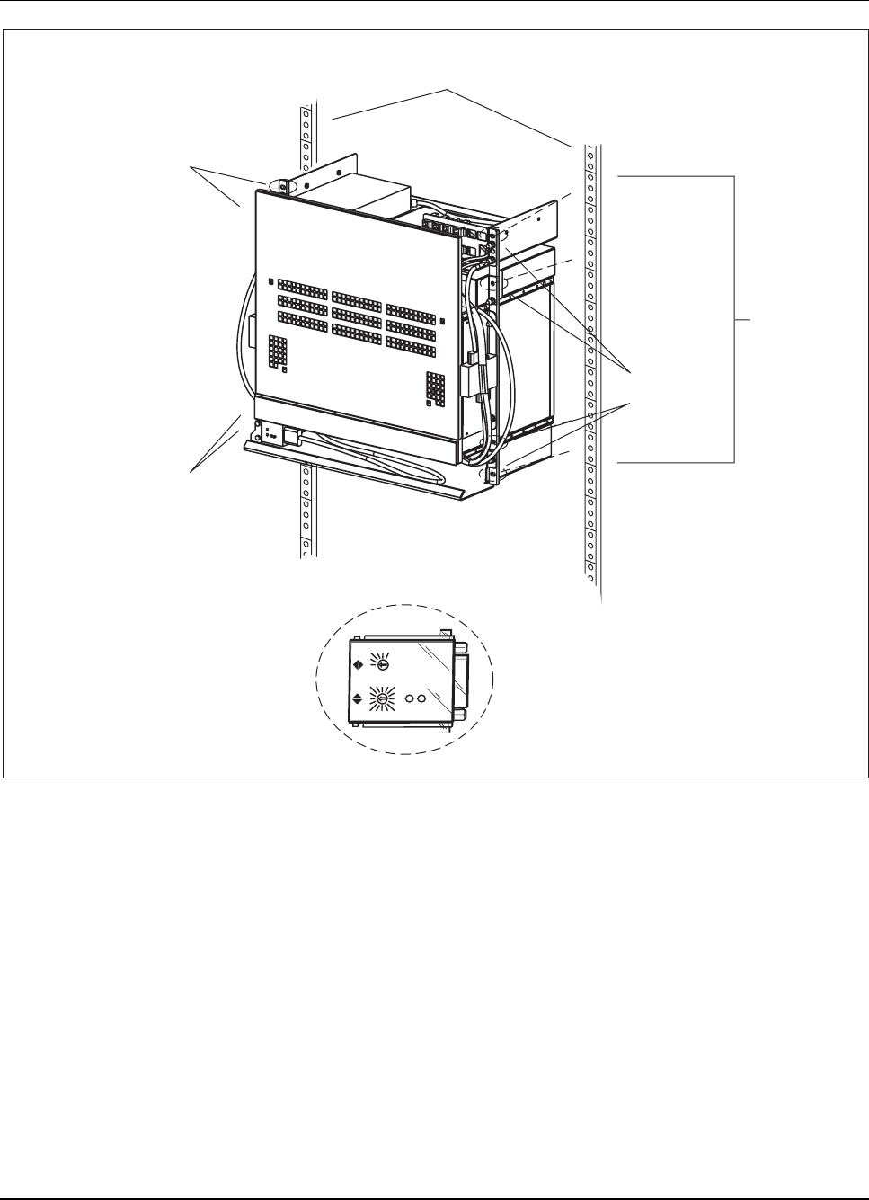
RBS 884 Pico (1900 MHz) CRI Installation
Rack/Cabinet Rail
(Electronic Industries Association)
11 Rack
Spaces
Rack/Cabinet
Rail Mounting
Points for Screws
(Left Side,
Not Shown)
Rack/Cabinet
Rail Mounting
Points for
Screws
(Right Side)
Rack/Cabinet
Rail Mounting
Points for Screws
(Left Side,
Partially Shown)
012
3
4
5
6
7
8
9
10
11
12
13
14 15 ABC
D
E
F
Power
Error
CID Unit
(BGM 136 69)
CID Cabinet Identification
CRI Control and Radio Interface
Figure 3-7. CRI Rack Mount Subrack
5. Secure the CRI to the rack rail using four screws on each side. See
Figure 3-7 on page 3-17 for the locations of the screw mounting points.
Set CID Unit
6. Call the MSC and request an identification number for the Cabinet
Identifier (CID) unit.
7. Using the small flat-head screwdriver, set the rotary switches on the
CID unit to the identification number. See Figure 3-8 on page 3-18 for
an illustration of the CID unit.
1/1531-AE/LZB 119 3834 Uae Rev PA6 2001-04-04 3-17
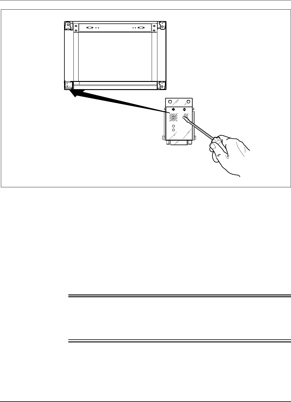
RBS 884 Pico (1900 MHz) CRI Installation
01 2
3
4
5
678910
11
12
13
14 15 AB C
D
E
Power
Error
01 2
3
4
5
678910
11
12
13
14 15 A B C
D
E
F
Power
Error
Figure 3-8. Setting the Cabinet Identifier
8. Go to Procedure 9.1 on page 3-50 to set the ETB switches and continue
the installation.
8.2 Installing CRI Floor Mount
The optional CRI Floor Mount Kit allows the RBS 884 Pico (1900 MHz)
customer to install the Pico CRI on the floor rather than in an equipment
rack. The cabinet in the RBS 884 Pico CRI Floor Mount Kit is an Ericsson
BYB 502 cabinet.
Warning!
The Pico CRI Floor Mount Kit does not meet IEC and Bellcore earthquake
requirements. A separate Earthquake Proof Kit must be used in order to meet
IEC 68-2-57 or Bellcore (Verteq 2; Zone 4) requirements.
3-18 1/1531-AE/LZB 119 3834 Uae Rev PA6 2001-04-04

RBS 884 Pico (1900 MHz) CRI Installation
Preparation
1. Verify that all materials have been received and inventoried as
described in Section 5 on page 3-9.
2. Install cable ladders.
3. Complete all site preparation according to Section 6 on page 3-11.
4. Verify that the appropriate bolts, washers, and mounting accessories
are available for securing the base to the floor. Concrete floor
mounting hardware is included with the CRI.
Note: Consider the floor type when determining the type of
hardware used to secure the base to the floor. The
diameter of bolts in the floor mounting hardware
cannot exceed 12 mm (M12 bolt or equivalent).
Disassemble the CRI Rack
5. Remove the CID unit from the air intake duct. The CID unit is
remounted later in the CRI installation procedure.
6. Remove the following parts that are not used with the CRI floor mount
cabinet (see Figure 3-9 on page 3-20):
•2 Rack Mount Bar Assemblies (SXK 107 5126/1)
•Rack Cover (SXA 120 6899/1)
•Air Intake Duct (SXA 120 6891/1)
•Identification Strip (to be installed on the rack-mount cable tray)
1/1531-AE/LZB 119 3834 Uae Rev PA6 2001-04-04 3-19
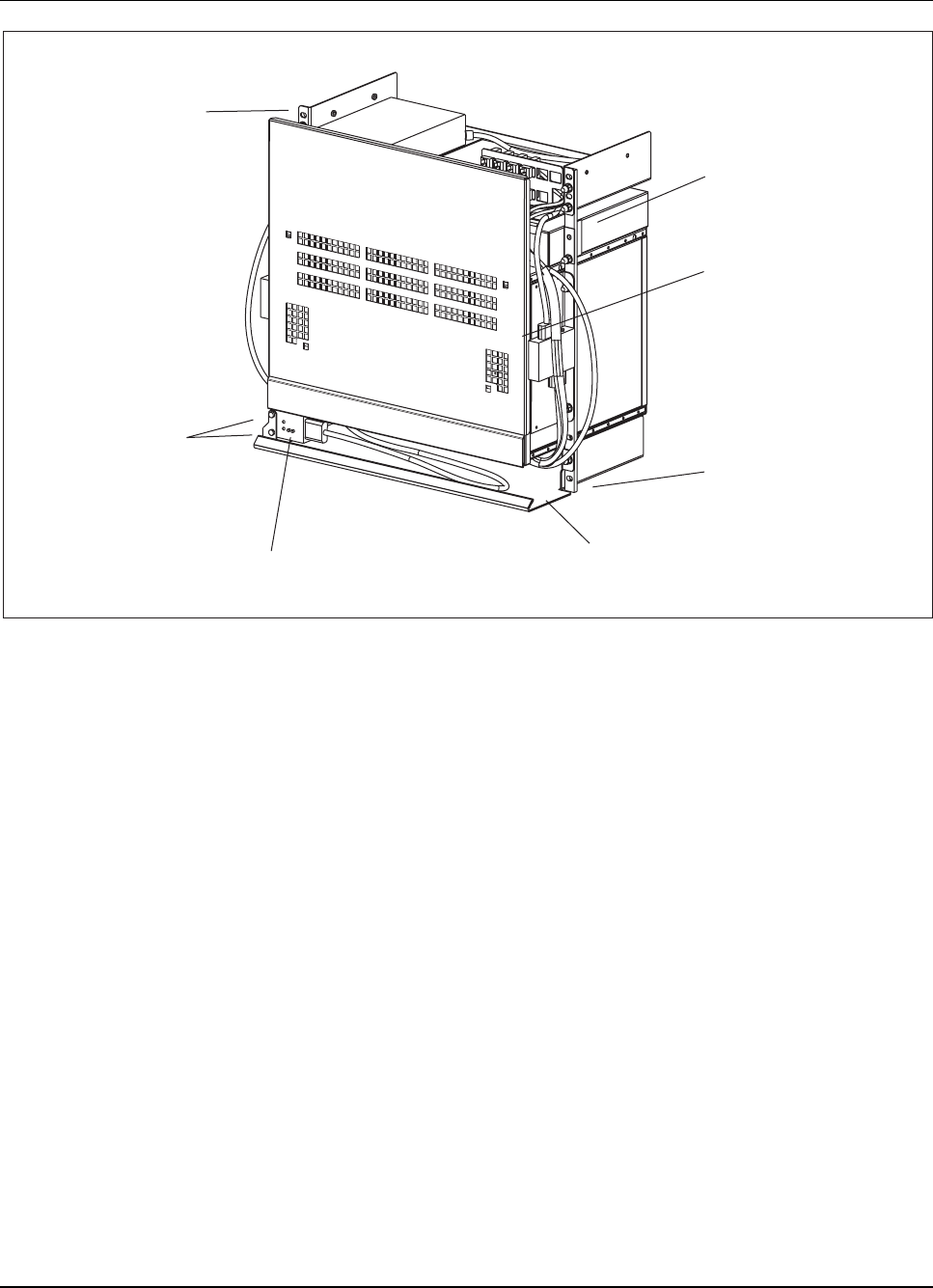
RBS 884 Pico (1900 MHz) CRI Installation
Cabinet Identification (CID) Unit
Rack Mount Bar Assembly
(SXK 107 5126/1)
Rack Cover
(SXA 120 6899/1)
Rack Mount Bar Assembly
(SXK 107 5126/1)
Air Intake Duct
(SXA 120 6891/1)
CID Unit Mounting Screws
(03/SBA 120 040/0060)
Rack Mount Bar Assembly
(SXK 107 5126/1)
Figure 3-9. CRI Rack Mount
Secure the Base to the Floor
7. Place the mounting base (SXA 123 2023/1) on the floor in the position
specified in the Floor Plan Drawing (found in the Site Installation
Documents). If the Floor Plan Drawing does not exist, consult the
site engineer.
Note: Unless otherwise stated in the Floor Plan Drawing,
bases must be placed a minimum distance of 30 mm
from any wall.
8. On the floor, mark the fixing holes for the base (as shown in Figure
3-10 on page 3-21 and Figure 3-11 on page 3-21).
3-20 1/1531-AE/LZB 119 3834 Uae Rev PA6 2001-04-04
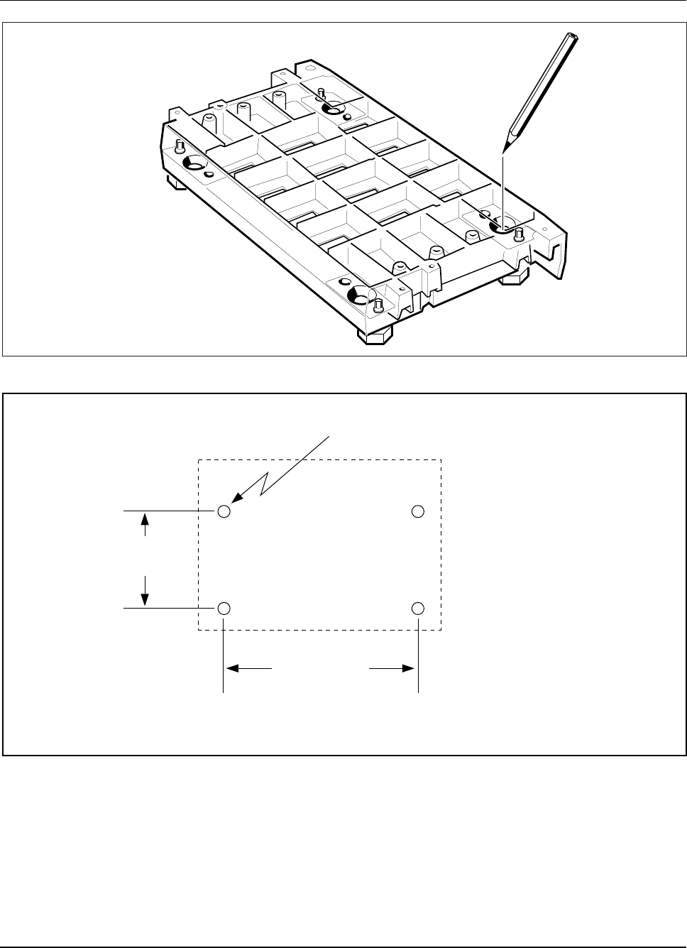
RBS 884 Pico (1900 MHz) CRI Installation
Figure 3-10. Marking the Fixing Hole Locations
15.76 in
(400 mm)
9,77 in
(248 mm)
.70 (11/16") inch diameter x 6.0 inches deep
(18 mm)
NOTE: Verify anchor bolt hole size requirements before drilling holes
Figure 3-11. Anchor Bolt Spacing for RBS Pico Equipment Base
9. Using a suitable drill size, drill the holes in the floor, as shown in
Figure 3-12 on page 3-22, to a depth suitable to the floor composition
1/1531-AE/LZB 119 3834 Uae Rev PA6 2001-04-04 3-21
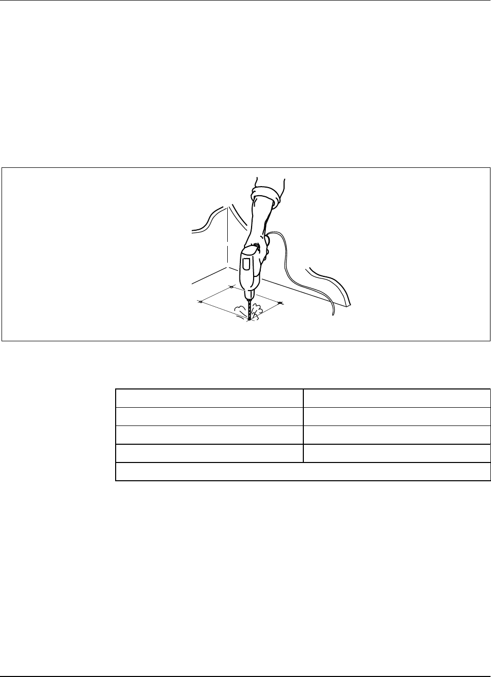
RBS 884 Pico (1900 MHz) CRI Installation
and using a suitable drill size. The base contains four anchor holes.
Use eye protectors and ear protectors.
Note: The floor-mounting bolts must match the material
of the floor and any additional requirements, such
as earthquake protection. The diameter of the bolts
must not exceed 12 mm (12M bolt or an equivalent).
Five expander bolts, suitable for concrete or brick
floors, are included in the BYB 502 hardware
kit. Refer to Table 3-1 on page 3-22 for technical
information on these expander bolts.
Figure 3-12. Drilling the Fixing Holes
Table 3-1. Technical Data – Expander Bolt
Bolt product number NSV 905 0805
Drill diameter 8mm
Total bolt length 90 mm
Minimum depth of drilled hole 75 mm
Note: This bolt does not meet the requirements for full earthquake protection.
Level the Base
10. Place the base on its correct place on the floor.
Note: The figures in this sequence show installation on
concrete floor, other floor arrangements may look
slightly different.
11. Ensure the leveling feet are tightened completely into the base.
3-22 1/1531-AE/LZB 119 3834 Uae Rev PA6 2001-04-04
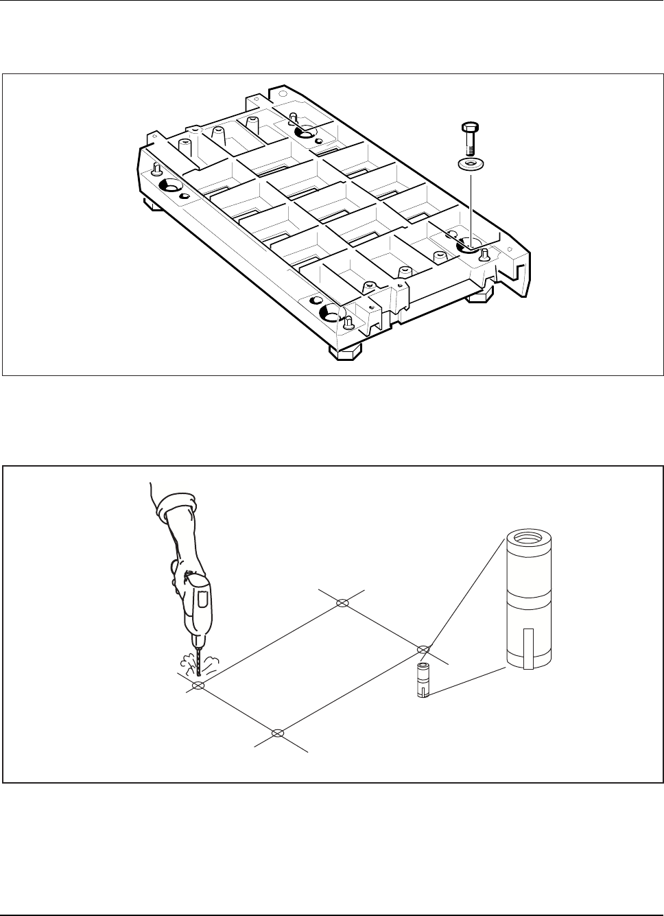
RBS 884 Pico (1900 MHz) CRI Installation
12. Insert the four expander bolts with washers in the base without
tightening them, as shown in Figure 3-13 on page 3-23.
Figure 3-13. Installing the Base Bolts
13. If expander bolts are not used, insert four lead anchors (plugs) in the
drilled holes (see Figure 3-14 on page 3-23).
Figure 3-14. Inserting Anchors in the Drilled Holes
1/1531-AE/LZB 119 3834 Uae Rev PA6 2001-04-04 3-23
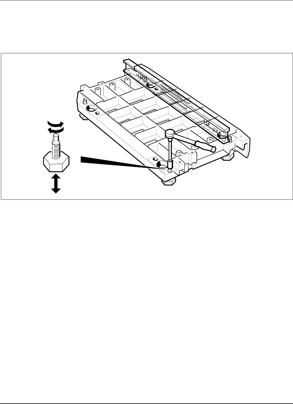
RBS 884 Pico (1900 MHz) CRI Installation
14. Place a level on the rear of the base, as shown in Figure 3-15 on page
3-24, and adjust the feet so that the base is level.
Note: If the base is uneven, start adjusting the foot in the
highest corner of the base.
Figure 3-15. Leveling the Rear of the Base
15. Place the level on the left and right sides of the base, as shown in
Figure 3-16 on page 3-25, and adjust the feet until the base is level.
3-24 1/1531-AE/LZB 119 3834 Uae Rev PA6 2001-04-04
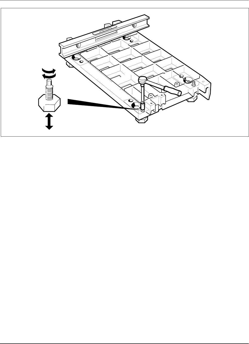
RBS 884 Pico (1900 MHz) CRI Installation
Figure 3-16. Leveling the Sides of the Base
Tighten the Bolts
16. Tighten the left rear bolt, as shown in Figure 3-17 on page 3-26.
Note: Tighten ordinary M12 bolts to torque setting 70 Nm.
Note: M8 bolts can be tightened only to torque setting
24 Nm and do not give earthquake protection.
1/1531-AE/LZB 119 3834 Uae Rev PA6 2001-04-04 3-25
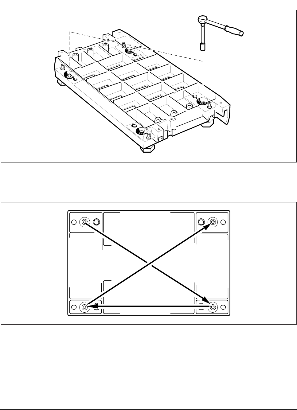
RBS 884 Pico (1900 MHz) CRI Installation
Figure 3-17. Tightening the Base Bolts
17. Tighten the remaining bolts diagonally, as shown in Figure 3-18 on
page 3-26.
Figure 3-18. Order in which to Tighten the Base Bolts
Mount the Protection Plate
18. Position the protection plate (SXA 123 2038/1) on the base, as shown
in Figure 3-19 on page 3-27.
3-26 1/1531-AE/LZB 119 3834 Uae Rev PA6 2001-04-04
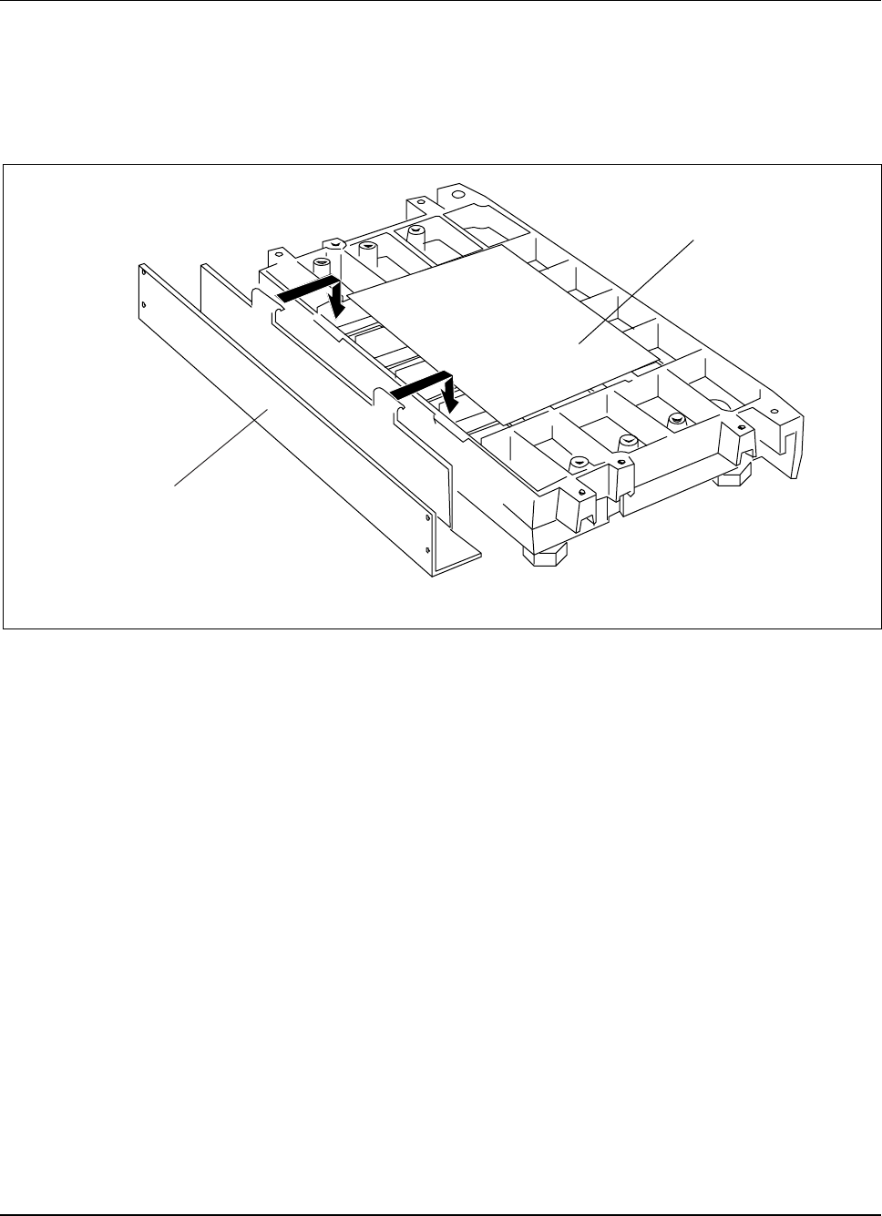
RBS 884 Pico (1900 MHz) CRI Installation
Mount the Cable Chute
19. Hook the cable chute (SXA 105 9360/1) on the front edge of the base
as shown in Figure 3-19 on page 3-27.
Cable Chute
Protection Plate
Figure 3-19. Hooking the Cable Chute onto the Base
Install the Cable Shelf and Identification Strip
20. Position the CRI cabinet on the floor with the opening facing up.
See Figure 3-20 on page 3-28.
1/1531-AE/LZB 119 3834 Uae Rev PA6 2001-04-04 3-27
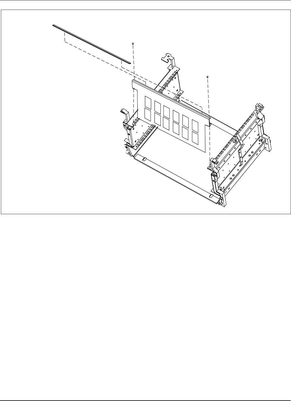
RBS 884 Pico (1900 MHz) CRI Installation
Identification Strip
Cable Shelf
CRI Cabinet
Figure 3-20. Cable Shelf Installation
21. InstalltheidentificationstripremovedinStep6onpage3-19onthe
cable shelf. See Figure 3-20 on page 3-28.
22. Use two Torx (TX 20) screws to install the cable shelf. See Figure
3-20 on page 3-28.
23. Install eight captive nuts in positions 1, 2, 23, and 24 on both of the
rear flanges in the CRI cabinet. See Figure 3-21 on page 3-29.
3-28 1/1531-AE/LZB 119 3834 Uae Rev PA6 2001-04-04
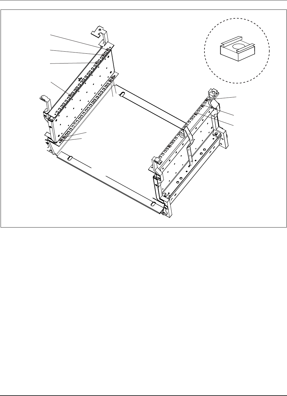
RBS 884 Pico (1900 MHz) CRI Installation
Captive Nut
1
3
6
18
Front Flange
Captive Nut
Locations
Front Flange
Captive Nut
Locations
Rear Flange
Captive Nut
Locations
1
3
6
23
18
24
21
Rear Flange
Captive Nut Locations:
1, 2, 23, and 24
Figure 3-21. CRI Cabinet Captive Nut Installation
24. Install eight captive nuts in positions 1, 3, 6, and 18 on both of the
front flanges in the CRI cabinet. See Figure 3-21 on page 3-29.
Install the Rear Plate
25. Install the rear sheet metal plate in the cabinet and insert, but do not
tighten, eight Torx (TX 30) screws. See Figure 3-22 on page 3-30.
1/1531-AE/LZB 119 3834 Uae Rev PA6 2001-04-04 3-29
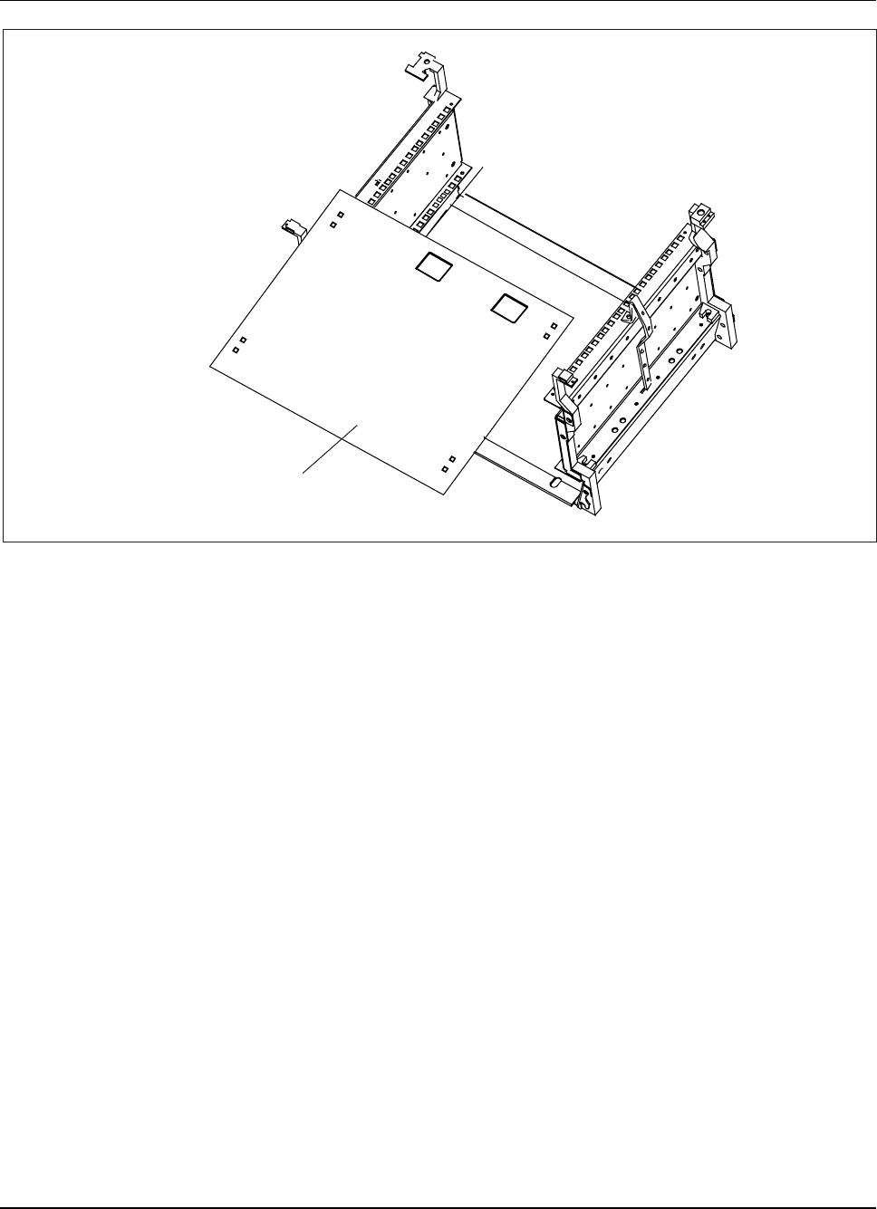
RBS 884 Pico (1900 MHz) CRI Installation
Rear Plate
Figure 3-22. Rear Plate Installation
Install the Fan Unit and CRI Subrack
26. Install the fan unit in the cabinet and insert, but do not tighten, four
Torx (TX 30) screws.(Figure 3-23 on page 3-31)
3-30 1/1531-AE/LZB 119 3834 Uae Rev PA6 2001-04-04
RBS 884 Pico (1900 MHz) CRI Installation
Fan Unit
(BKV 301 246/2401)
CRI Cabinet (BYB502)
Control and Radio Interface
CRI
Figure 3-23. Fan Unit Installation
27. Install the subrack in the cabinet and insert, but do not tighten, four
Torx (TX 30) screws.(Figure 3-24 on page 3-32).
1/1531-AE/LZB 119 3834 Uae Rev PA6 2001-04-04 3-31
RBS 884 Pico (1900 MHz) CRI Installation
CRI Subrack
(BFD 749 31/1 or 31/2)
CRI Cabinet (BYB502)
Control and Radio Interface
CRI
Figure 3-24. CRI Subrack Installation
28. Adjust the position of the fan unit and the CRI subrack so that no space
exists between the two units. See Figure 3-25 on page 3-33.
3-32 1/1531-AE/LZB 119 3834 Uae Rev PA6 2001-04-04
RBS 884 Pico (1900 MHz) CRI Installation
Fan Unit
CRI
Subrack
Note: Adjust the
Fan Unit and the
CRI subrack so
there is no space
between the two
units.
Figure 3-25. Fan Unit and Subrack Adjustment
29. Tighten the four Torx (TX 30) screws to secure the fan unit. See
Figure 3-23 on page 3-31.
30. Tighten the four Torx (TX 30) screws to secure the CRI subrack.
See Figure 3-24 on page 3-32.
Install the CID Unit
31. Use two Torx (TX 30) screws to install the CID unit. See Figure 3-26
on page 3-34. (Cables are not shown in this illustration.)
1/1531-AE/LZB 119 3834 Uae Rev PA6 2001-04-04 3-33
RBS 884 Pico (1900 MHz) CRI Installation
1
01 2
3
4
5
678910
1
12
13
1415
AB C
D
E
F
Power
Error
Cabinet Identification
(CID) Unit
D-Type
Connector
The fan unit and the cable shelf are not shown.
CRI Cabinet (BYB502)
Control and Radio Interface
CRI
Figure 3-26. CID Unit Installation
32. Call the MSC and request a CID number. Set the CID unit to the
corresponding identifier (ID) using a small, flat-head screwdriver.
See Figure 3-26 on page 3-34.
Secure the Pico BYB 502 Cabinet on the Base
33. Install, but do not tighten, two rear cabinet bolts (03/SBA 178
080/0400).
Note: Do not tighten the bolts because the CRI cabinet
must slide onto the bolts in Step 35 on page 3-35.
3-34 1/1531-AE/LZB 119 3834 Uae Rev PA6 2001-04-04
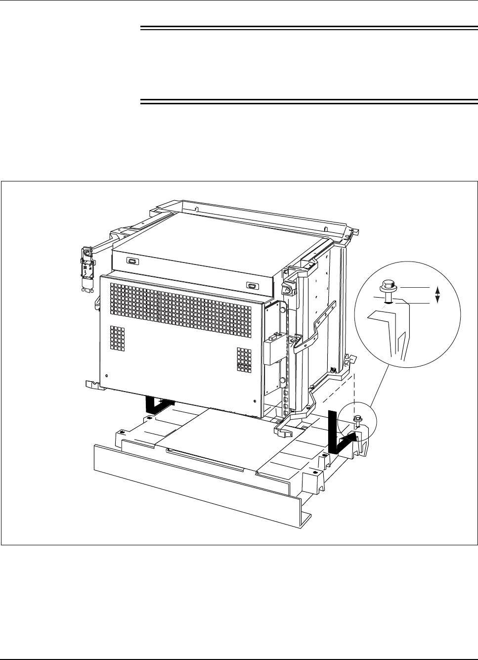
RBS 884 Pico (1900 MHz) CRI Installation
34.
Warning!
The partially-equipped Pico CRI cabinet weighs approximately 30 kg
(66 lb). Ericsson recommends that two persons are present during the
installation.
Slide the CRI cabinet on the base.
35. Align the slots on the rear of the CRI subrack unit with the rear cabinet
bolts (see Figure 3-27 on page 3-35).
20 mm
01 2
3
4
5
678910
11
12
13
1415
ABC
D
E
F
Power
Error
Figure 3-27. Securing CRI on Base
36. Insert, but do not tighten, one bolt (provided in hardware kit) into each
of the six remaining fixing holes, as shown in Figure 3-28 on page 3-36.
1/1531-AE/LZB 119 3834 Uae Rev PA6 2001-04-04 3-35
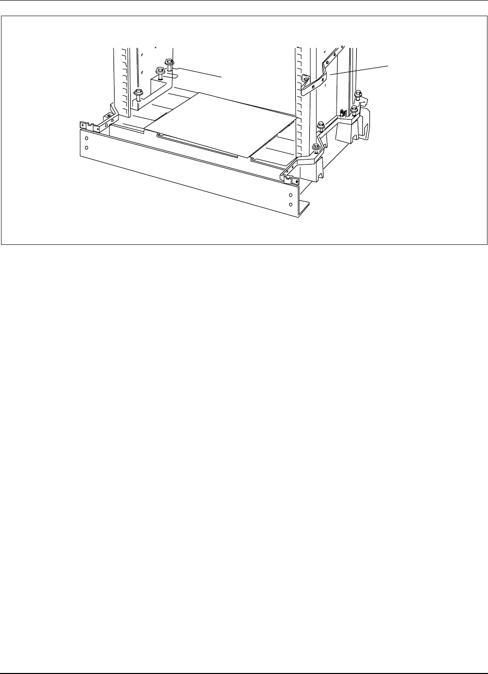
RBS 884 Pico (1900 MHz) CRI Installation
Cable
mounting
bar
Note: The RBS equipment is not shown.
Figure 3-28. Bolting the CRI Cabinet to the Base
37. Making sure that the cabinet is in line with the base, tighten the eight
bolts to torque setting 20 Nm.
Note: To simplify this step, the cable mounting bar can be
temporarily removed.
Ground the CRI Floor Mount Cabinet
38. If not already present, run a 35 mm or larger insulated cable (RBS
ground cable, from Grounding Wire Kit 4/NTM 201 201) on the
cable ladder that is located above the equipment. See the Cable Way
Drawing in the Site Installation Documents.
39. Connect the RBS ground cable to the site ground bar (see the Floor
Plan Drawing in the Site Installation Documents ) as shown in Figure
3-29 on page 3-37.
3-36 1/1531-AE/LZB 119 3834 Uae Rev PA6 2001-04-04
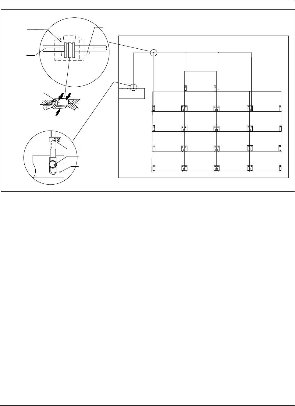
RBS 884 Pico (1900 MHz) CRI Installation
Cabinet room
Site
ground
bar
RBS ground cable (35 mm )
Cable clip
Bolt, nut, washer
Site ground
bar
Plastic
cover
Cabinet ground
cable
RBS ground
cable
Crimp connector
2
25 mm
2
25 mm
2
25 mm
2
25 mm
2
35 mm
2
Figure 3-29. Example of Ground Cable Connection
40. Run a 25 mm²or thicker insulated cabinet ground cable (included in
Grounding Cabinet Kit 5/NTM 201 201) from the RBS ground cable,
vertically down to the right front fixing hole of the cabinet. See Figure
3-29 on page 3-37.
Note: If the site has mixed BYB 401 and BYB 502
cabinets, the grounding cables are attached to the
front fixing holes on the same side of all top cabinets.
41. Use a crimp connector (from Grounding Wire Kit 4/NTM 201 201) and
the crimp tool to connect the cabinet ground cable to the RBS ground
cable, as shown in Figure 3-29 on page 3-37.
Use the cable stripper or a knife to remove the sheath (insulation)
from the cables to allow galvanic contact between the cables.
42. Put a plastic cover (from Grounding Wire Kit 4/NTM 201 201) on the
crimp connector and seal it with tape.
43. Cut the cabinet ground cable to a suitable length (it must reach the
connection point on the cabinet).
44. Remove enough cable sheath from the free end of the cabinet ground
cable for the cable lug (from Grounding Cabinet Kit 5/NTM 201 201).
1/1531-AE/LZB 119 3834 Uae Rev PA6 2001-04-04 3-37
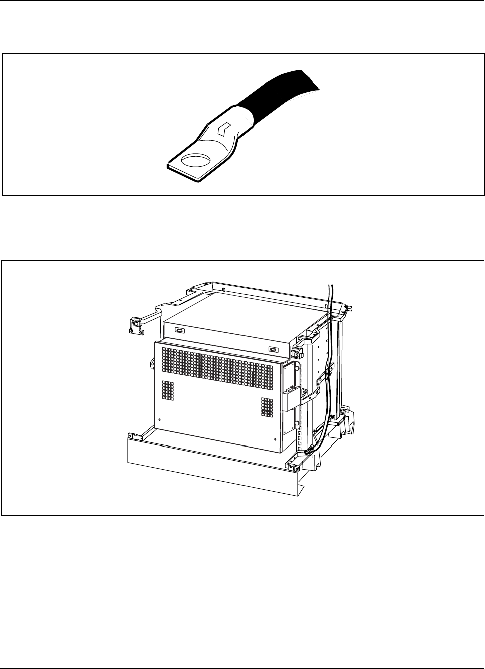
RBS 884 Pico (1900 MHz) CRI Installation
45. Use the crimp tool to attach the cable lug to the cable. See Figure
3-30 on page 3-38.
Figure 3-30. Cable Lug Crimped on Ground Cable
46. Connect the ground cable to the Pico BYB 502 cabinet, as shown in
Figure 3-31 on page 3-38.
Figure 3-31. Grounding the Pico Cabinet (BYB 502)
Install the Power Shelf
47. Install a right and left power shelf mounting bracket using two Torx
(TX 20) screws for each side. See Figure 3-32 on page 3-39.
3-38 1/1531-AE/LZB 119 3834 Uae Rev PA6 2001-04-04
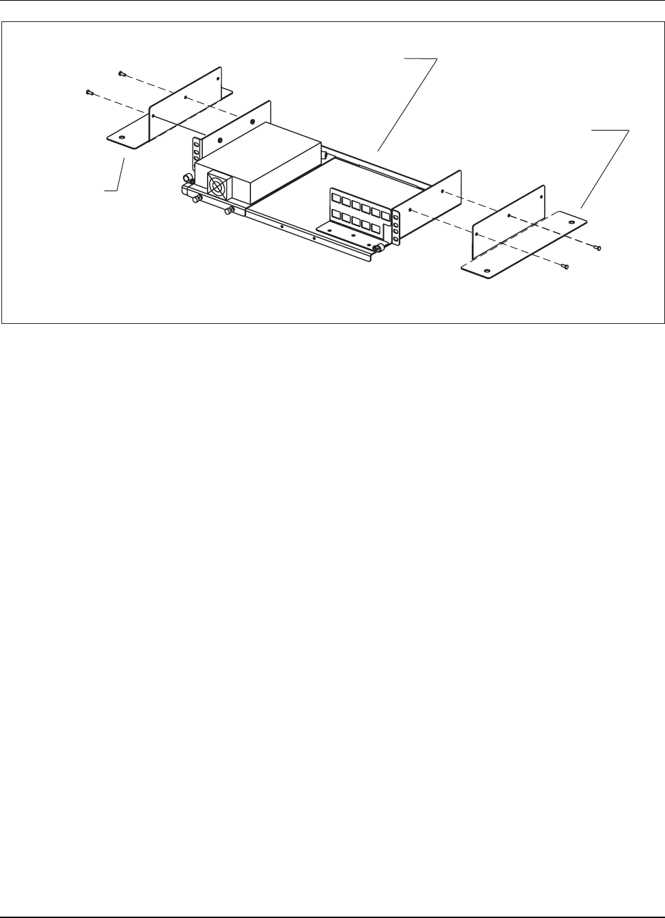
RBS 884 Pico (1900 MHz) CRI Installation
Power Shelf
(SXK 107 3756/1)
Right Bracket
(SXA 120 6892/1)
Left Bracket
(SXA 120 6892/1)
Figure 3-32. Power Shelf Brackets
48. Position the power shelf on the CRI cabinet. SeeFigure3-33on
page 3-40.
49. Install one bolt in the rear hole on each power shelf bracket. See
Figure 3-33 on page 3-40.
Note: Do not tighten the bolts.
1/1531-AE/LZB 119 3834 Uae Rev PA6 2001-04-04 3-39
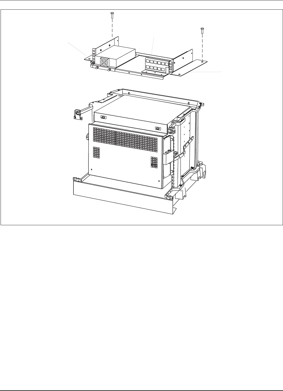
RBS 884 Pico (1900 MHz) CRI Installation
CRI Cabinet
Power Shelf
Bracket
Bracket
Figure 3-33. Power Shelf Installation
Connect the Power Cables
50. Connect the DC power cable (Y-cable) (RPM 113 1476/1) from the
power supply to the left and the right DC filter. See Figure 3-34
on page 3-41.
3-40 1/1531-AE/LZB 119 3834 Uae Rev PA6 2001-04-04
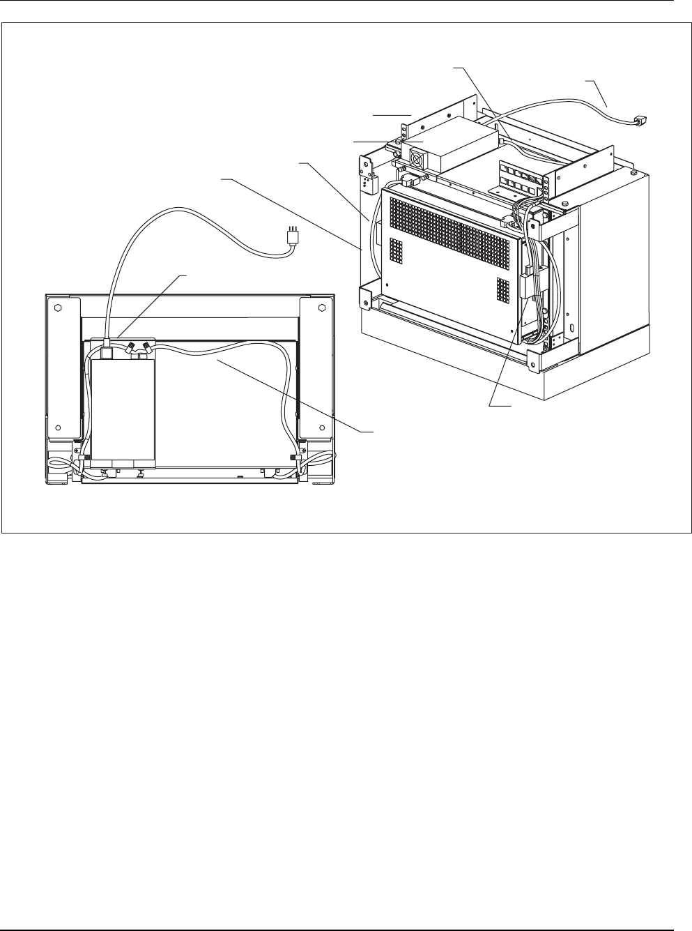
RBS 884 Pico (1900 MHz) CRI Installation
Power Supply Top View
DC Power Cable (Y-Cable)
(RPM 113 1476/1)
Right DC Filter
Power Shelf
AC Power Cord
(RPM 945 324)
AC Power Cord
(RPM 945 324)
DC Power Cable (Y-Cable)
(RPM 113 1476/1)
Power Supply
Left DC Filter
AC Connector
Fan Power Cable
(RPM 513 941 00900)
CRI Front View
Figure 3-34. Power Cable Installation
51. Connect the Line Cord (RPM 945 324) to the AC connector on the rear
panel of the power supply. See Figure 3-34 on page 3-41.
52. Install the cables on the fan unit. See Figure 3-34 on page 3-41.
53. To install the CRI boards later, go to Step 8 on page 3-87 to complete
this portion of the CRI installation.
54. To install the CRI boards now, go to Procedure 9.1 on page 3-50 to set
the ETB switches and continue the installation.
8.3 Installing a Pico CRI Cabinet with Existing Macro Cabinets
The RBS 884 Pico (1900 MHz) cabinet is an Ericsson BYB 502 cabinet.
BYB 502 cabinets can be installed with existing Macro BYB 401 or Macro
1/1531-AE/LZB 119 3834 Uae Rev PA6 2001-04-04 3-41

RBS 884 Pico (1900 MHz) CRI Installation
BYB 502 cabinets. For other cabinet configurations, refer to RBS 884 Macro
Installation and Hardware Replacement Manual (EN/LZB 119 3307).
Warning!
The partially-equipped Pico CRI BYB 502 cabinet weighs approximately
30 kg (66 lb). Ericsson recommends that two persons are present during
the installation.
8.3.1 Installing a Pico BYB 502 Base Next to a BYB 401 Base
1. If a cabinet is installed on the present base, remove the right front
fixing bolt (assuming the new base is to be installed to the right).
2. Use earthquake protection according to local regulations. See RBS
884 Macro Installation and Hardware Replacement Manual for IEC
68-2-57 and Bellcore (Verteq 2: Zone 4) requirements. Use earthquake
kit 15/BYB 502/1.
3. To measure the distance between the bases, place two double-mount
brackets (placed on each other) between the bases at the rear fixing
holes, and one double-mount bracket (with inserted bolts) on the front
fixing holes. See Figure 3-35 on page 3-43.
3-42 1/1531-AE/LZB 119 3834 Uae Rev PA6 2001-04-04
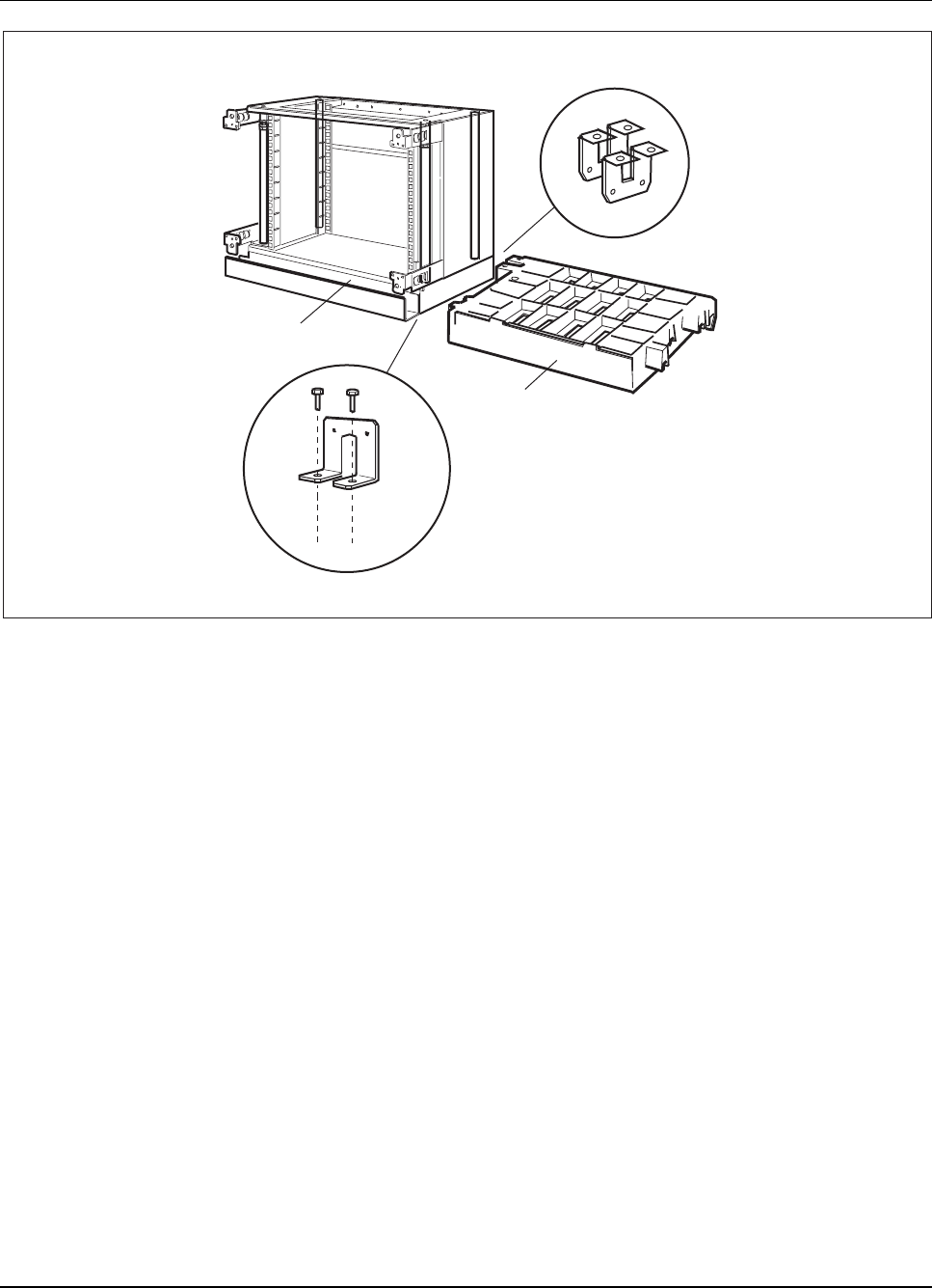
RBS 884 Pico (1900 MHz) CRI Installation
BYB 502 base
BYB 401 base
Figure 3-35. Measuring the Correct Separation Between the Bases
4. Drill holes in the floor, insert the bolts, level the base, tighten the bolts
(M12 bolts to torque setting 70 Nm, M8 bolts to 24 Nm), mount the
cable chute, mount any remaining bases, and mount a base side cover
as described in Step 8 on page 3-87.
5. Remove the three double-mount brackets that were used to measure
the separation between the bases.
8.3.2 Installing a Pico BYB 502 Cabinet Next to a BYB 401 Cabinet
Site Preparation
1. Before beginning the installation, remove the door from each cabinet.
1/1531-AE/LZB 119 3834 Uae Rev PA6 2001-04-04 3-43
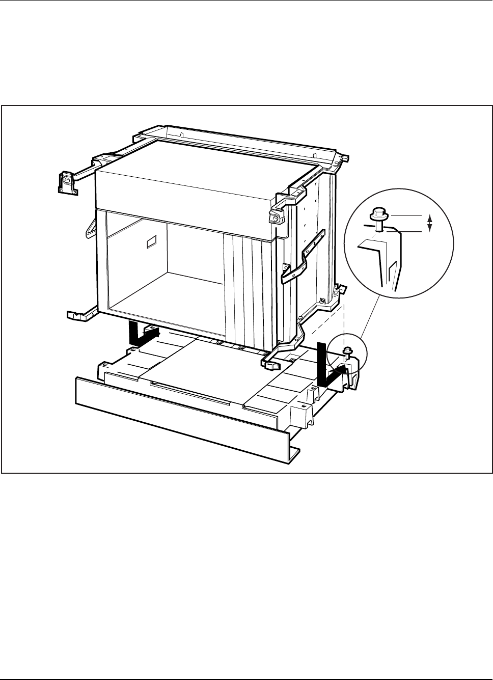
RBS 884 Pico (1900 MHz) CRI Installation
Row A Installation
2. Insert one bolt into each of the two rear screw holes on the previously
installed base, and make sure that the distance between the bolt head
and the base is more than 20 mm. See Figure 3-36 on page 3-44.
20 mm
Figure 3-36. Distance between the Bolt Head and the Base
3. Slide the appropriate cabinet into its correct position on the base,
and insert one bolt into each of the six remaining fixing holes. Do
not tighten the bolts yet.
4. Connect the cabinets at the front fixing holes. Use a double-mount
bracket and two washers (six-sided) under the double-mount bracket
on the BYB 401 side. No washers are used on the BYB 502 side.
5. Mount a contact bar between BYB 401 and BYB 502 cabinets. Hook
the contact bar on the premounted screws. Use a Torx screwdriver
TX20 to tighten the screws. See Figure 3-37 on page 3-45.
3-44 1/1531-AE/LZB 119 3834 Uae Rev PA6 2001-04-04
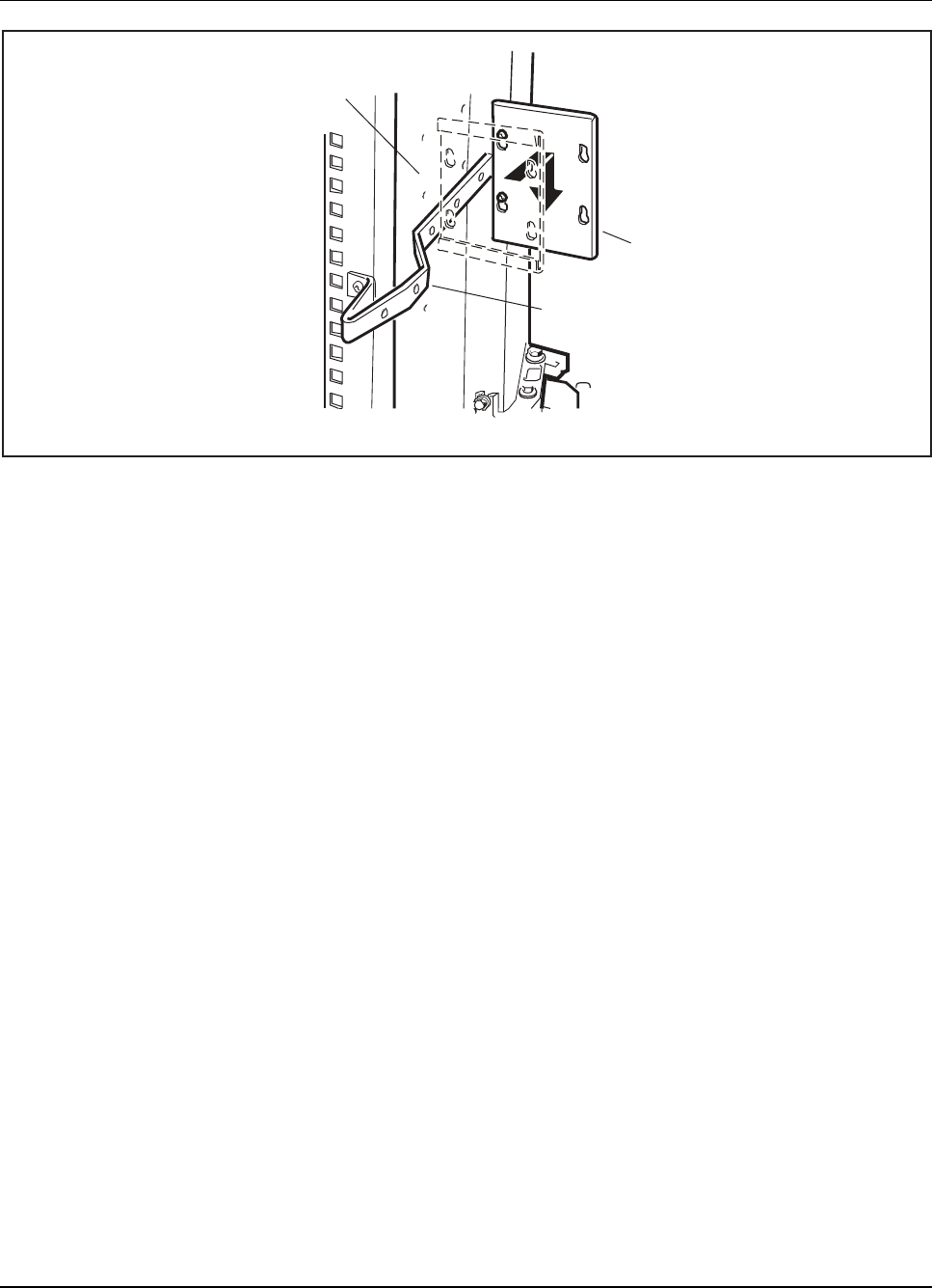
RBS 884 Pico (1900 MHz) CRI Installation
Cable mounting bar
Contact bar
Right side on
cabinet to the left
Figure 3-37. Contact Bar
6. Making sure that the cabinet is in line with the base, tighten the eight
bolts to torque setting 20 Nm.
7. Perform the Power (POWD) intercabinet cabling according to the
Terminal Drawings and Site Installation Documentation.
Note: Do not install the Pico CRI power unit and power
shelf when using Macro POWD intercabinet cabling.
8.3.3 Installing a Pico BYB 502 Cabinet on Top of a BYB 502 Cabinet
Site Preparation
1. Before beginning the installation, remove the door from each cabinet.
2. Remove the top cover from the supporting cabinet.
Row B Installation
3. Insert one bolt into each of the two rear screw holes on the previously
installed base, and make sure that the distance between the bolt head
and the base is more than 20 mm. See Figure 3-38 on page 3-46.
1/1531-AE/LZB 119 3834 Uae Rev PA6 2001-04-04 3-45
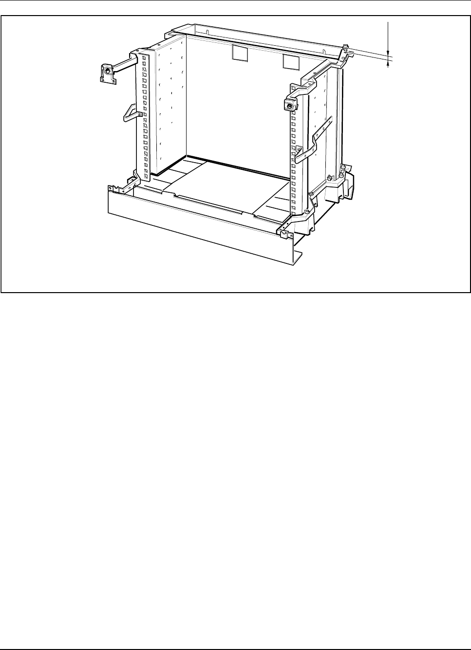
RBS 884 Pico (1900 MHz) CRI Installation
20 mm
>
Row A
Note: The RBS equipment is not shown.
Figure 3-38. Distance between Bolt Head and Cabinet Top
4. Slide the appropriate cabinet into its correct position on the cabinet in
Row A, as shown in Figure 3-39 on page 3-47.
3-46 1/1531-AE/LZB 119 3834 Uae Rev PA6 2001-04-04
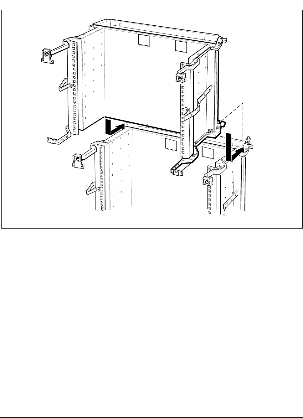
RBS 884 Pico (1900 MHz) CRI Installation
Row B
Row A
Note: The RBS equipment is not shown.
Figure 3-39. Sliding Cabinet into Position on Cabinet
5. Insert (but do not tighten) one bolt into each of the six remaining fixing
holes, as shown in Figure 3-39 on page 3-47.
6. Make sure that the cabinet is in line with the cabinet below and tighten
the eight bolts to torque setting 20 Nm.
Rows C, D, and E Installation
7. On the supporting cabinet, insert one bolt into each of the two rear
screw holes. Make sure that the distance between the bolt head and the
cabinet top is more than 20 mm, as shown in Figure 3-40 on page 3-48.
8. Slide the appropriate cabinet into its correct position on the cabinet
below, as shown in Figure 3-40 on page 3-48.
1/1531-AE/LZB 119 3834 Uae Rev PA6 2001-04-04 3-47
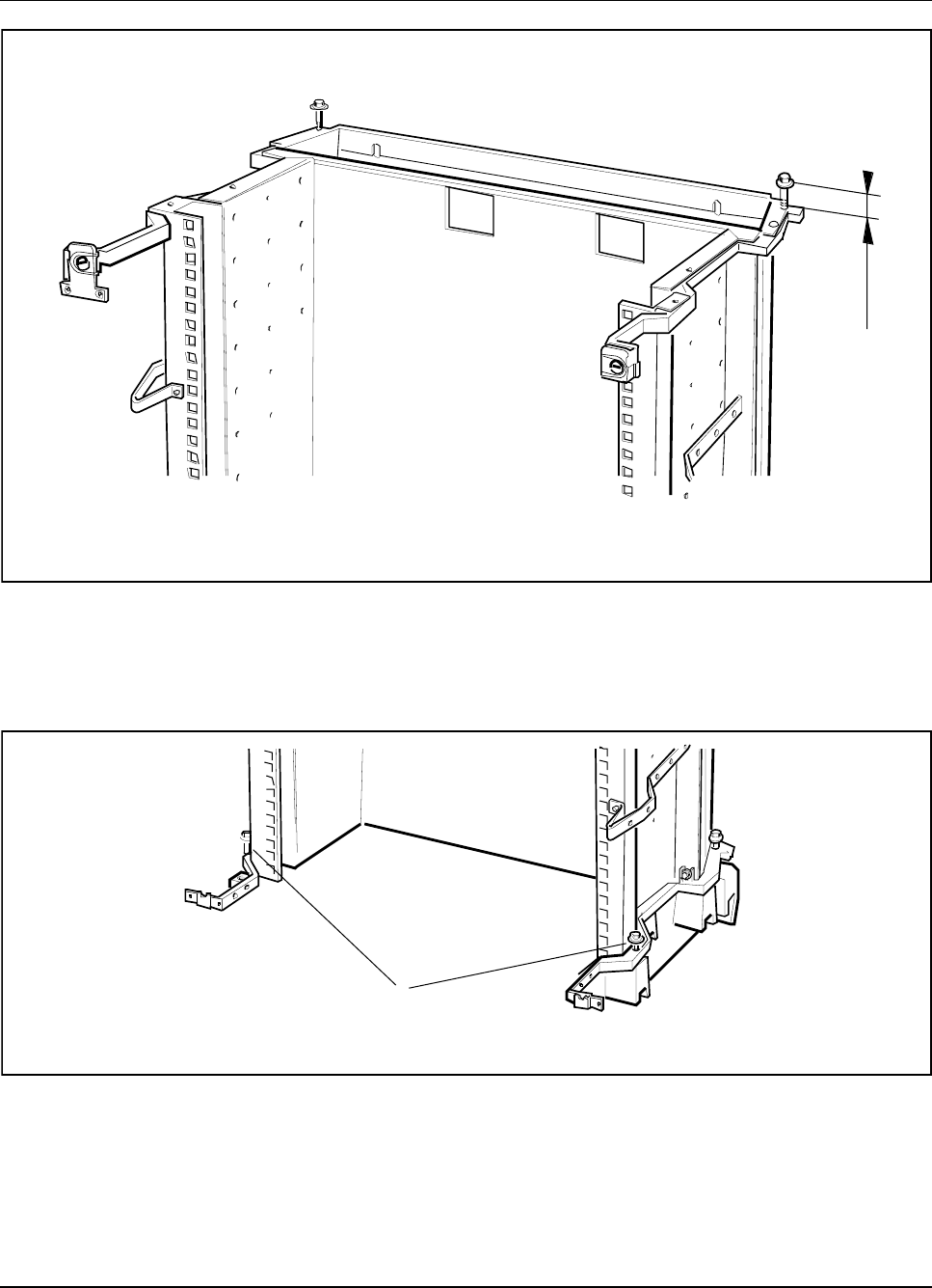
RBS 884 Pico (1900 MHz) CRI Installation
20 mm
>
Note: The RBS equipment is not shown.
Figure 3-40. Inserting Bolts in Cabinet Rows C, D, or E
9. Insert (but do not tighten) one bolt into each of the two front fixing
holes, as shown in Figure 3-41 on page 3-48. Only four bolts are
requiredtofixacabinetinrowC,D,orE.
Bolts for front fixing holes
Note: The RBS equipment is not shown.
Figure 3-41. Inserting Bolts in the Front Fixing Holes for Rows C, D, or E
10. Make sure that the cabinet is in line with the cabinet below and tighten
the four bolts to torque setting 20 Nm.
3-48 1/1531-AE/LZB 119 3834 Uae Rev PA6 2001-04-04
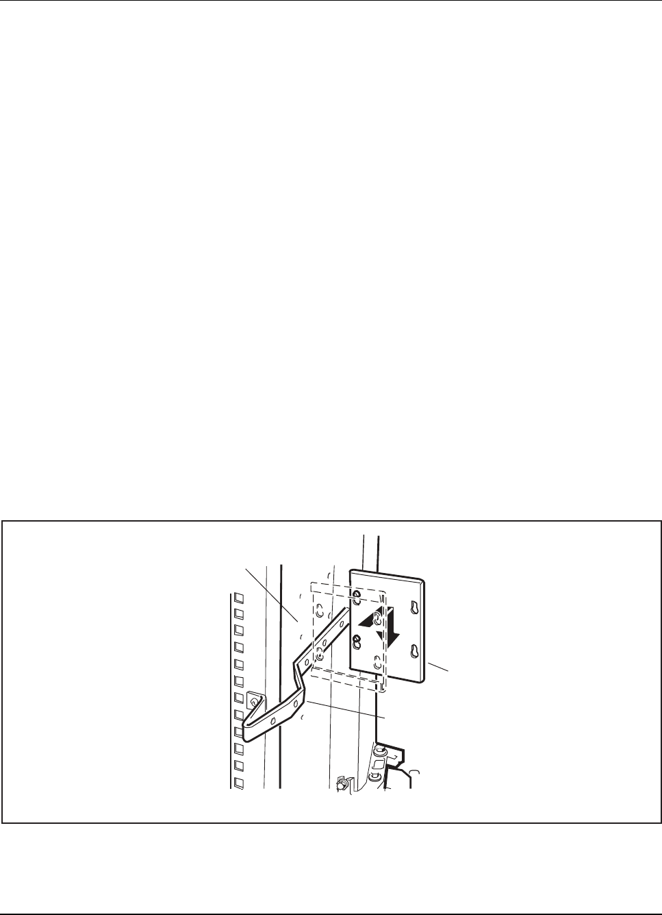
RBS 884 Pico (1900 MHz) CRI Installation
8.3.4 Installing a Pico BYB 502 Cabinet on Top of a BYB 401 Cabinet
Site Preparation
1. Before beginning the installation, remove the door from each cabinet.
Rows B, C, or D Installation
2. Insert one bolt into each of the two rear screw holes on the previously
installed base, and make sure that the distance between the bolt head
and the base is more than 20 mm (Figure 3-40 on page 3-48).
3. Slide the appropriate cabinet into its correct position on the base,
and insert one bolt into each of the six remaining fixing holes. Do
not tighten the bolts yet.
4. Use a double-mount bracket and two washers (six-sided) under the
double-mount bracket on the BYB 401 side to connect the cabinets at
the front fixing holes . No washers are used on the BYB 502 side.
5. Mount a contact bar between the BYB 401 and the BYB 502 cabinets.
Hook the contact bar on the premounted screws, and tighten the screws
using Torx screwdriver TX20 (Figure 3-42 on page 3-49).
Cable mounting bar
Contact bar
Right side on
cabinet to the left
Figure 3-42. Mounting the Contact Bar
1/1531-AE/LZB 119 3834 Uae Rev PA6 2001-04-04 3-49

RBS 884 Pico (1900 MHz) CRI Installation
8.3.5 Grounding the Rack Top Cabinet
1. Connect the ground cable to the left front fixing bolt.
8.3.6 Cabinet Installation Completion
1. For free-standing racks and visible rear sides, mount a cover strip
(SXA 123 2025/1) into the space between the cabinets at the rear side.
2. Use four bolts to mount the top cover. Use an M13 or M10 box wrench
to tighten the bolts.
3. When the upgrade is completed, notify the MSC that modification of
the Data Transcript is required.
9 CRI Hardware Units and Switches
9.1 Setting ETB Switches
Preparations
1. Remove the rack cover or the EMI cover from the CRI magazine.
Unit Removal
2. Use the extractor tool (LTD 117 02) to remove the ETB boards from
slots 5 and 6 in the CRI subrack.
3. Check the backplane connector for bent or broken pins.
4. Locate the switches on the ETB boards. See Figure 3-43 on page 3-51
for the location of the switches.
3-50 1/1531-AE/LZB 119 3834 Uae Rev PA6 2001-04-04
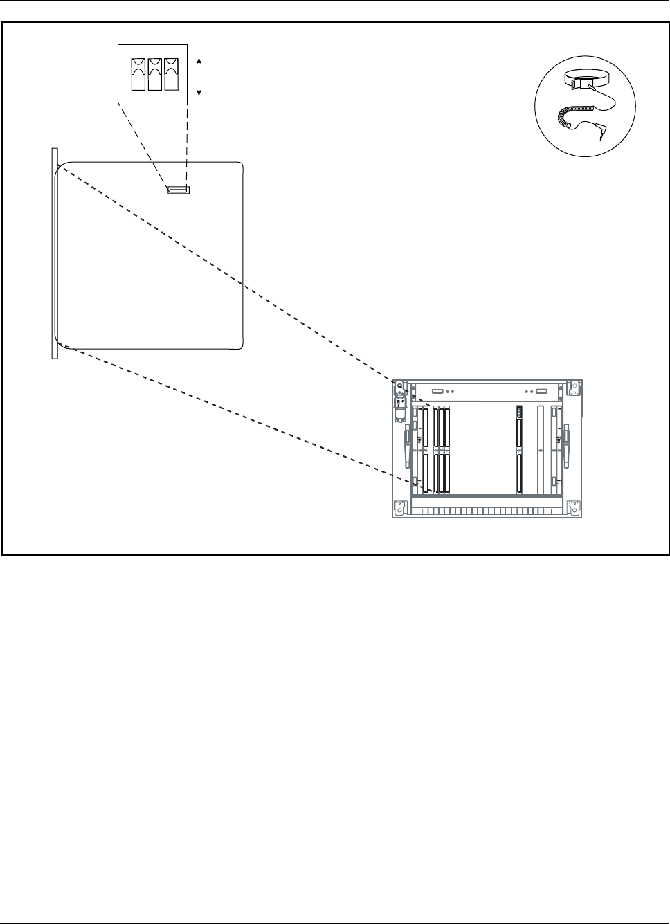
RBS 884 Pico (1900 MHz) CRI Installation
DIP switches
1
0
123
ON
Control and Radio Interface
Exchange Terminal
Board (ETB)
012
3
4
5
678910
11
12
13
1415 AB C
D
E
Power
Error
DC/DC
1 ST
R
2
ETB
5 ETB
6
EMRPS
7
EMRPS
8
EMRPS
9
EMRPS
10
EMRPS
11
EMRPS
12
EMRPS
13
EMRPS
14
EMRPS
15
EMRPS
16
EMRPS
17
ELI EELILI
18
19 20
EMRP
4
DC/DC
23
Figure 3-43. Location of ETB Unit DIP Switches
DIP Switch Settings
5. Configure the switches on the ETB unit. Refer to Table 3-2 on page
3-52 or Table 3-3 on page 3-52 for the applicable ETB DIP switch
settings.
Note: Consult the CSU documentation for additional
information.
1/1531-AE/LZB 119 3834 Uae Rev PA6 2001-04-04 3-51

RBS 884 Pico (1900 MHz) CRI Installation
Table 3-2. ETB-24 DIP Switch Settings
Distance (meters)
CSU – CRI
ETB-24 DIP Switch Position 1–3
0–35 011
25 –65 101
55 –95 001
85 –125 110
115 –155 010
145 –185 100
175 –210 000
Note: The ETB-24 DIP switches indicate the line length in the transmit direction.
Table 3-3. ETB-32 DIP Switch Settings
ETB-32 DIP Switch Number
1 2
Receive Transmit
Switch On = grounded
Switch Off = not grounded
Note: The ETB-32 DIP switches indicate the PCM grounding direction. With twisted-pair
conductors, the outer conductor is grounded. With coaxial cable, the screen
is grounded.
6. Reinsert the ETB unit into the designated slot in the CRI magazine.
9.2 Installing ELI Unit and Setting Switches
The RBS 884 Pico (1900 MHz) subrack is shipped with one factory-installed
ELI unit. One ELI unit supports one T1/E1 link (three Radio Heads). If extra
links are required, additional ELI units (up to a maximum of four) can be
installed.
Preparations
1. Verify that additional ELI units, if required, are present at the site.
Note: Each ELI unit supports up to four Radio Heads.
3-52 1/1531-AE/LZB 119 3834 Uae Rev PA6 2001-04-04

RBS 884 Pico (1900 MHz) CRI Installation
2. Remove the rack cover or the EMI cover from the CRI magazine.
RTT Unit Removal: Macro CRI
3. When colocating an RBS 884 Pico in an RBS 884 Macro CRI
magazine, use the extractor tool (LTD 117 02) to remove the RTT unit,
if present, from slot 17, 18, 19, or 20 in the CRI subrack. Store the
RTT unit in an ESD bag.
4. Check the backplane connector for bent or broken pins.
ELI Unit Removal: Pico CRI
5. At the top of the CRI magazine, carefully press the plastic retaining
catch upwards. Use the extractor tool to remove the ELI unit from
the CRI magazine
6. Make sure the ELI unit, rear connector, and the associated back plane
connector do not have any bent or broken pins.
7. If additional ELI units are present, remove ELI units (ROF 137 2776/1)
from the ESD bags and insert the units into positions 18, 19, and
20 in the CRI cabinet.
ELI Switch Settings
8. Locate the switches on the ELI unit(s). See Figure 3-44 on page 3-54
for the location of the DIP switches.
1/1531-AE/LZB 119 3834 Uae Rev PA6 2001-04-04 3-53
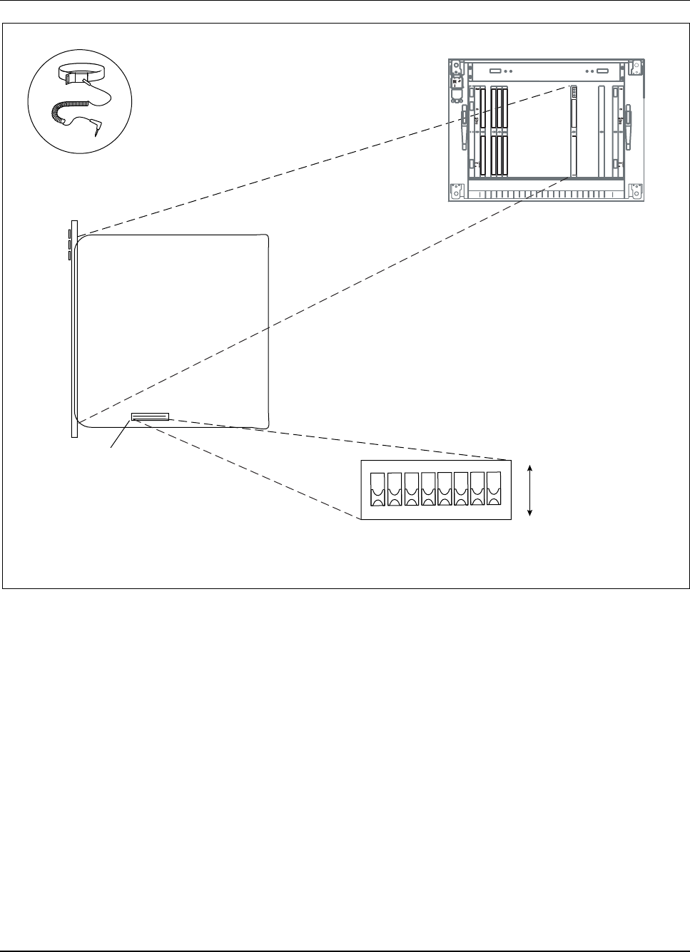
RBS 884 Pico (1900 MHz) CRI Installation
DIP switches 1
0
12345678
ON
Control and Radio
Interface
Enhanced Link
Interface (ELI) Unit
012
3
4
5
678910
11
12
13
1415 AB C
D
E
Power
Error
DC/DC
1 ST
R
2
ETB
5 ETB
6
EMRPS
7
EMRPS
8
EMRPS
9
EMRPS
10
EMRPS
11
EMRPS
12
EMRPS
13
EMRPS
14
EMRP S
15
EMRPS
16
17
ELI EELILIELI
18
19 20
EMRP
4
DC/DC
23
Figure 3-44. ELI Unit and Switch Location
9. Set the ELI DIP switches. If using T1 lines, refer to Table 3-4 on page
3-55 and Table 3-6 on page 3-56. If using E1 lines, refer to Table 3-5
on page 3-56 and Table 3-7 on page 3-57.
3-54 1/1531-AE/LZB 119 3834 Uae Rev PA6 2001-04-04
RBS 884 Pico (1900 MHz) CRI Installation
8
76
5
4321
E1
Tx PCM
Ground
shield
E1
Rx PCM
Ground
shield
Link Type Line Build
Out (2)
or
E1 Line
Impedence
Line Build
Out (1) or
Attenuation
(1)
Line Build
Out (0) or
Attenuation
(0)
PCM Link
Mode (1)
PCM Link
Mode (0)
Figure 3-45. Identification of ELI Unit DIP Switches
Table 3-4. DIP Switches T1 Leased
Parameter DIP Switch Number 1 –8
PCM T1 Short Haul
Distance (meters) CSU –CRI
0–35 000111xx
25 –65 001011xx
55 –95 000011xx
85 –125 001101xx
115 –155 000101xx
145 –185 001001xx
175 –210 000001xx
PCM T1 Long Haul (attenuation)
Note: Consult the CSU documentation for the attenuation setting.
0dB 1000x1xx
Recommended
-7.5 dB 1010x1xx
-15 dB 1001x1xx
-22.5 dB 1011x1xx
Note: ON = 1
OFF = 0
1/1531-AE/LZB 119 3834 Uae Rev PA6 2001-04-04 3-55

RBS 884 Pico (1900 MHz) CRI Installation
Table 3-5. ELI DIP Switch Settings E1 Leased
Parameter DIP Switch Number 1 –8
E1 Short Haul (impedance)
120-ohm twisted-pair 01xx01xx
75-ohm coaxial 01xx11xx
E1 Long Haul (impedance)
120-ohm twisted-pair 11xx01xx
75-ohm coaxial 11xx11xx
E1 Short Haul (ground shield)
Both Rx and Tx shields are grounded
(75-ohm coaxial)
01xxx111
Rx shield not grounded and Tx shield
grounded (120-ohm twisted-pair)
01xxx101
E1 Long Haul (ground shield)
Both Rx and Tx shields are grounded 11xxx111
Rx shield not grounded and Tx shield
grounded (120-ohm twisted-pair)
11xxx101
Note: ON = 1
OFF = 0
Table 3-6. ELI DIP Switch Settings for T1 Proprietary or Non-Leased
Parameter DIP Switch Number 1 –8
T1 Long Haul (attenuation)
0dB 1000x0xx
Recommended
-7.5 dB 1010x0xx
-15 dB 10001x0xx
-22.5 dB 1011x0xx
Note: 1=On
0=Off
3-56 1/1531-AE/LZB 119 3834 Uae Rev PA6 2001-04-04

RBS 884 Pico (1900 MHz) CRI Installation
Table 3-7. ELI DIP Switch Settings for E1 Proprietary or Non-Leased
Parameter DIP Switch Position 1 –8
E1 Short Haul (impedance)
120-ohm twisted-pair 01xx00xx
75-ohm coaxial 01xx10xx
E1 Long Haul (impedance)
120-ohm twisted-pair 11xx00xx
75-ohm coaxial 11xx10xx
E1 Short Haul (ground shield)
Both Rx and Tx shields are grounded 01xx0011
Rx shield not grounded and Tx shield
grounded (120-ohm twisted-pair)
01xx0001
E1 Long Haul (ground shield)
Both Rx and Tx shields are grounded 11xx0011
Rx shield not grounded and Tx shield
grounded (120-ohm twisted-pair)
11xx0001
Note: 1=On
0=Off
10. Insert the ELI units in the CRI magazine (slots 17, 18, 19, and 20).
9.3 Installing EMRPS Units and Address Plugs
The RBS 884 Pico (1900 MHz) subrack is partially equipped at the factory.
The EMRPS units are installed by the customer as described in the following
procedure.
Preparations
1. Verify the quantity of EMRPS units. One EMRPS unit for each Radio
Head should be included.
Note: If the number of Radio Heads is not known, consult
the next level of maintenance support or the site
engineer.
2. Remove the rack cover or the EMI cover from the CRI magazine.
Refer to Figure 3-46 on page 3-58 for a view of the partially-equipped
subrack.
1/1531-AE/LZB 119 3834 Uae Rev PA6 2001-04-04 3-57
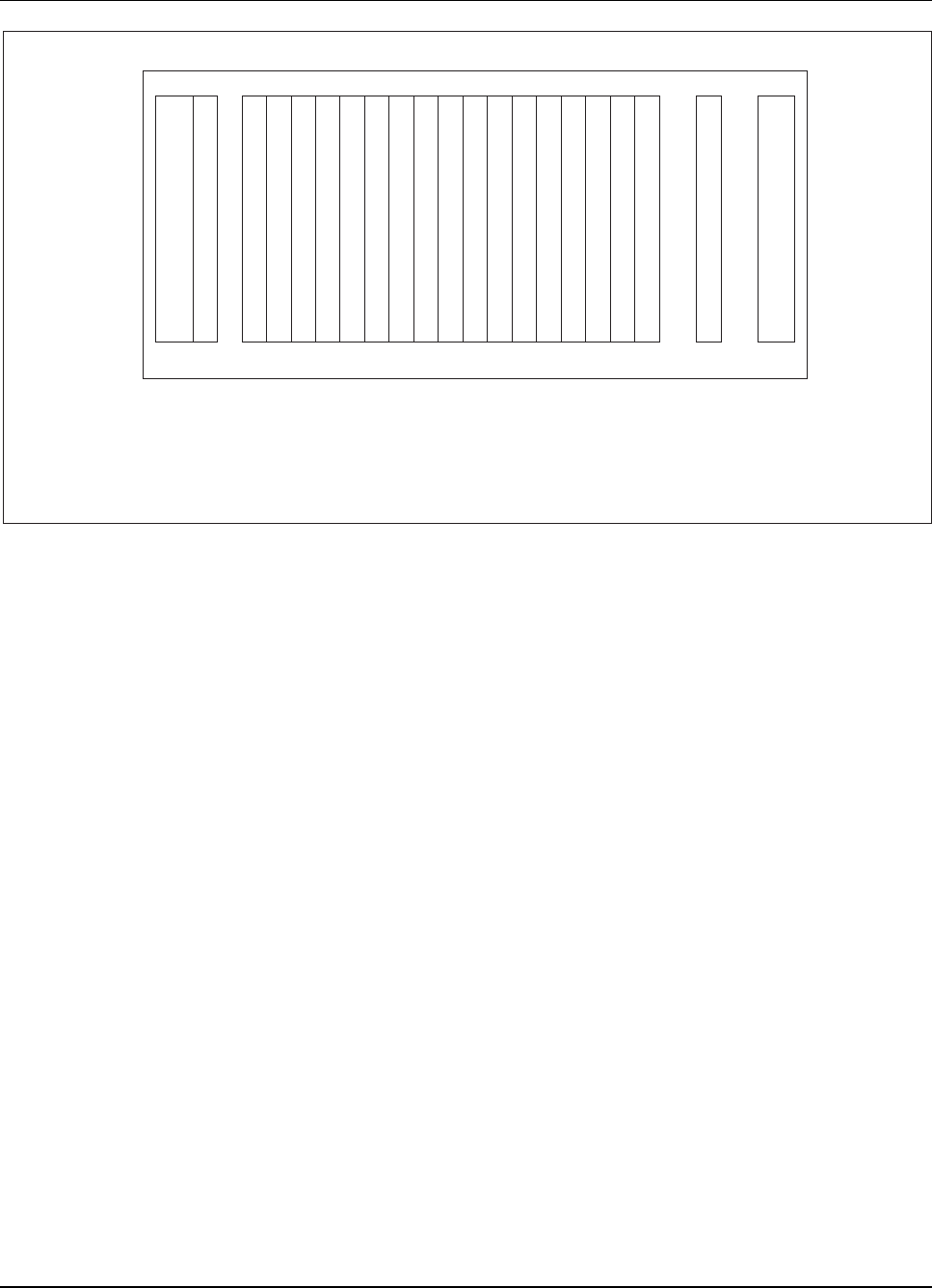
RBS 884 Pico (1900 MHz) CRI Installation
Enhanced Link Interface
Extention Module Regional Processor
Extention Module Regional Processor with Device Speech Bus Access
Exchange Terminal Board
Signaling Terminal Regional
ELI
EMRP
EMRPS
ETB
STR
DC
/
DC
S
T
R
E
M
R
P
DC
/
DC
E
T
B
E
T
B
R
I
T
S
W
1 2 4 5 6 7 8 9 10 11 12 13 14 15 16 17 18 19 20 22 23
E
L
I
Figure 3-46. RBS 884 Pico (1900 MHz)CRI (as delivered)
Install EMRPS Unit(s)
3. Remove the EMRPS unit (ROF 131 8217/3) from its ESD bag and
insert it into the proper slot in the CRI magazine. Refer to Figure
3-47 on page 3-59 for the location of the EMRPS slots in the Pico
CRI subrack.
3-58 1/1531-AE/LZB 119 3834 Uae Rev PA6 2001-04-04
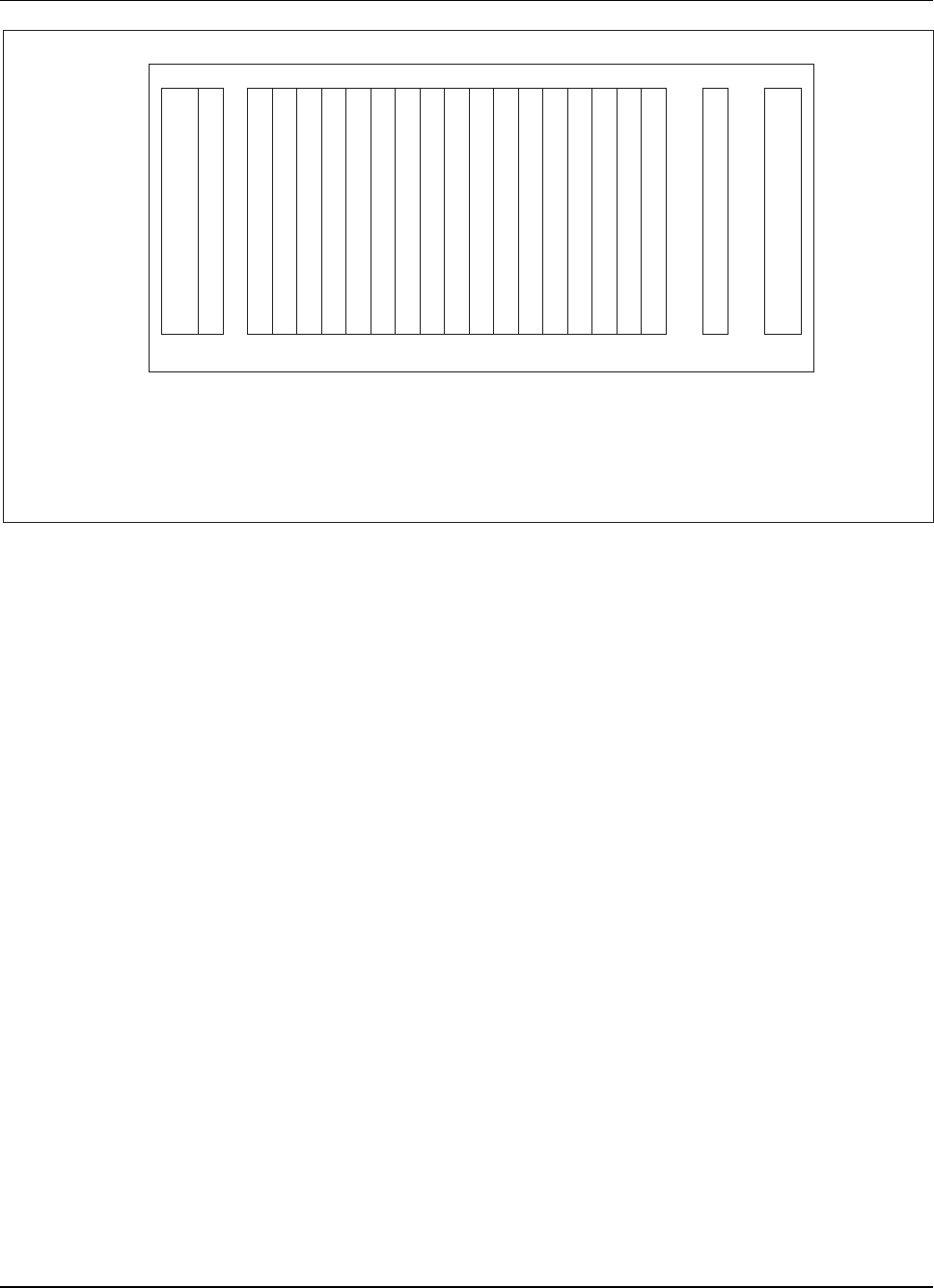
RBS 884 Pico (1900 MHz) CRI Installation
Enhanced Link Interface
Extention Module Regional Processor
Extention Module Regional Processor with Device Speech Bus Access
Exchange Terminal Board
Signaling Terminal Regional
ELI
EMRP
EMRPS
ETB
STR
DC
/
DC
S
T
R
E
M
R
P
DC
/
DC
E
T
B
E
T
B
E
M
R
P
S
E
M
R
P
S
E
M
R
P
S
E
M
R
P
S
E
M
R
P
S
E
M
R
P
S
E
M
R
P
S
E
M
R
P
S
E
M
R
P
S
E
M
R
P
S
R
I
T
S
W
1 2 4 5 6 7 8 9 10 11 12 13 14 15 16 17 18 19 20 22 23
E
L
I
Figure 3-47. Pico CRI EMRPS Positions
4. If colocating an RBS 884 Pico in an RBS 884 Macro CRI magazine,
install additional EMRPS units as required. One EMRPS unit supports
one Radio Head. Refer to Figure 3-48 on page 3-60 for the location of
the EMRPS slots in the Macro CRI subrack.
Note: If the number of Radio Heads to be supported by
the CRI is not known, consult the next level of
maintenance support or the site engineer.
1/1531-AE/LZB 119 3834 Uae Rev PA6 2001-04-04 3-59
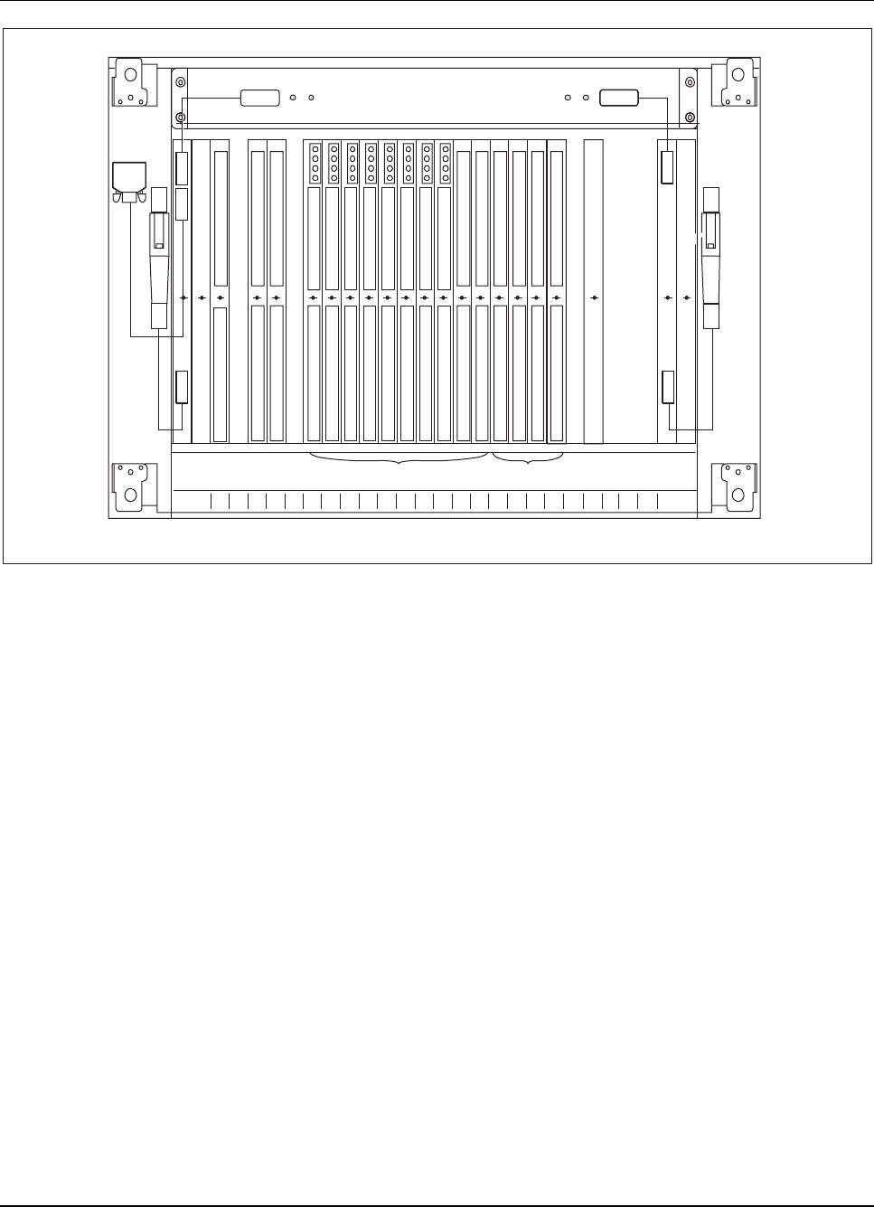
RBS 884 Pico (1900 MHz) CRI Installation
FAN
CID
DC/DC
+24V/
Ü5V/
Ü5V/
I
N
P
U
T
+24V
ON
I
N
P
U
T
+24V
ON
FAN
CI
D
DC/DC
+24V/
Ü5V/
Ü5V/
DC/DC
1 STR
2 STR
3 EMRP
4 ETB
5 ETB
6
EMRPS
RTT
7
EMRPS
RTT
8
EMRPS
RTT
9
EMRPS
RTT
10
EMRPS
RTT
11
EMRPS
RTT
12
EMRPS
RTT
13
EMRPS
RTT
14
EMRPS
RTT
15
EMRPS
RTT
16
EMRPS
RTT
17
EMRPS
RTT
18
RTT
ETB
19
RTT
ETB
20
DCH
21
RITSW
22
DC/DC
23
EMRPS Positions RTT-ELI Positions
Figure 3-48. Macro CRI EMRPS Positions
5. Repeat Step 3 on page 3-58 until all EMRPS units are installed.
Note: The number of EMRPS units is determined by the
number of Radio Heads. One EMRPS unit supports
one Radio Head.
6. Insert the correct EMRP address plug into the EMRPS unit(s) in
numerical order. Refer to Figure 3-49 on page 3-61 for the location of
the EMRP plugs.
Note: Eleven EMRP Address Plugs (RNV 991 03/02-12)
are provided with each EMRPS Kit. Store the extra
address plugs with the radio equipment spare parts.
3-60 1/1531-AE/LZB 119 3834 Uae Rev PA6 2001-04-04
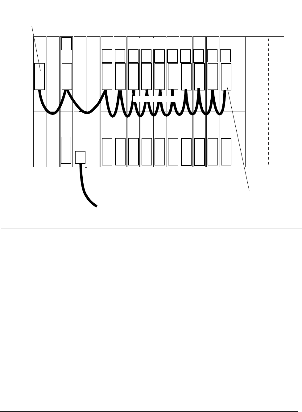
RBS 884 Pico (1900 MHz) CRI Installation
EMRPSEMRPSEMRPSEMRPSEMRPSEMRPSEMRPSEMRPS
ETBETB
EMRP
STRSTRDC/DC
PCM Link 1
(Position B3 for 100/120 ohm or B4 for 75 ohm)
/1
/2 /3 /4 /5 /6 /7 /8 /9
T
Terminating plug
(RNV 991 223/004),
connected on top of
address plug
(Position 16, A2).
EMRP Bus-A
RNV 991 03/02-12
EMRPS Address Plugs (A1)
(A2)
(A3)
(A4)
(B1)
(B2)
(B3)
(B4)
ELIEMRPSEMRPS
/10 /11
2 3 4 5 6 7 8 9 10 11 12 13 14 15 16 171
Pico (1900 MHz) CRI
EMRP Bus Cable
Figure 3-49. ELI Unit, Plugs, and Cables in CRI Cabinet
7. Remove the terminating plug (RNV 991 223/004) from the EMRP
unit (position 4).
8. Insert the terminating plug (RNV 991 223/004) into the address plug
connector on the right-most EMRPS unit.
Install EMRPS Cables
9. Locate the EMRPS cable labels and attach the labels as indicated in
Table 3-8 on page 3-62.
1/1531-AE/LZB 119 3834 Uae Rev PA6 2001-04-04 3-61

RBS 884 Pico (1900 MHz) CRI Installation
Table 3-8. EMRPS Bus Cable Labels
Label Origination Address Destination
Address
EMRP 4A * 3F
EMRPS7A*3F
EMRP EMRPS1
EMRPS7A*3F
EMRPS8A*3F
EMRPS1 EMRPS2
EMRPS8A*3F
EMRPS9A*3F
EMRPS2 EMRPS3
EMRPS9A*3F
EMRPS 10A * 3F
EMRPS3 EMRPS4
EMRPS 10A * 3F
EMRPS 11A * 3F
EMRPS4 EMRPS5
EMRPS 11A * 3F
EMRPS 12A * 3F
EMRPS5 EMRPS6
EMRPS 12A * 3F
EMRPS 13A * 3F
EMRPS6 EMRPS7
EMRPS 13A * 3F
EMRPS 14A * 3F
EMRPS7 EMRPS8
EMRPS 14A * 3F
EMRPS 15A * 3F
EMRPS8 EMRPS9
EMRPS 15A * 3F
EMRPS 16A * 3F
EMRPS9 EMRPS10
Terminator
16A * 3F
Not Applicable EMRPS10
10. Use the information on the cable labels to link the EMRP cables (TSR
204 0201/300) to the referenced EMRPS units.
10 Equipment Cabling and Start-up
Warning!
Configure and cable the Radio Head(s) prior to starting these procedures.
Refer to Part 4, “Radio Head Installation.”
3-62 1/1531-AE/LZB 119 3834 Uae Rev PA6 2001-04-04

RBS 884 Pico (1900 MHz) CRI Installation
10.1 Cabling the CRI Hardware
10.1.1 Installing the ETB-ELI Sync Cable
Preparations
1. Locate the ETB-ELI sync cable.
Note: The ETB-ELI sync cable is required for non-leased
or proprietary connections. The sync cable is not
required for T1/E1 leased connections, although its
presence does not interfere with leased connections.
ETB-ELI Sync Cable
2. Connect the quarter-plug connectors on the ETB-ELI sync cable (RPM
113 7673) to ELI unit, positions 17–21, B4. Refer to Figure 3-50 on
page 3-64 for an example of the sync cable connections.
Note: The order in which the quarter-plugs are connected
does not affect the performance of the base station.
However, it is important to connect the first ELI
quarter-plug connector to one of the ELI units.
1/1531-AE/LZB 119 3834 Uae Rev PA6 2001-04-04 3-63
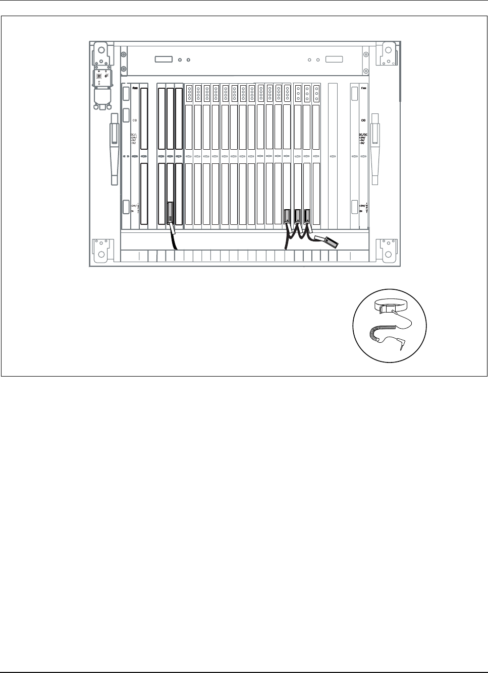
RBS 884 Pico (1900 MHz) CRI Installation
01 2
3
4
5
678910
11
12
13
14 15 AB C
D
E
Power
Error
DC/DC
1 ST
R
2
ETB
5 ETB
6
EMRPS
7
EMRPS
8
EMRPS
9
EMRPS
10
EMRPS
11
EMRPS
12
EMRPS
13
EMRPS
14
EMRPS
15
EMRPS
16
17
ELI EELILIELI
18
19 20
EMRP
4
DC/DC
23
Figure 3-50. Connecting the ETB-ELI Sync Cable to Three ELI Units
10.1.2 Leased T1/E1 Installation (Twisted-Pair Cable)
The following section provides installation information for network or leased
lines using T1/E1 100/120-ohm twisted pair cable.
For installation convenience, the CRI to Radio Head cabling information is
also included in Part 3, RBS 884 Pico (1900 MHz) CRI Installation.
3-64 1/1531-AE/LZB 119 3834 Uae Rev PA6 2001-04-04

RBS 884 Pico (1900 MHz) CRI Installation
Preparations
1. Ensure that the Radio Heads are properly installed and tested prior to
starting this installation procedure.
Note: The first or primary Radio Head in each link or link
group must be installed and connected to the PSTN.
Additional Radio Heads are installed after the initial
communication is established between the CRI and
the primary Radio Heads.
2. Determine the number of Radio Head link groups (usually determined
by the number of T1/E1 links). Refer to Figure 3-51 on page 3-66 and
Figure 3-52 on page 3-67 for configuration examples.
Note: If the number of Radio Heads or Radio Head link
groups to be connected to the CRI is not known,
consult the next level of maintenance support or
the site engineer.
1/1531-AE/LZB 119 3834 Uae Rev PA6 2001-04-04 3-65
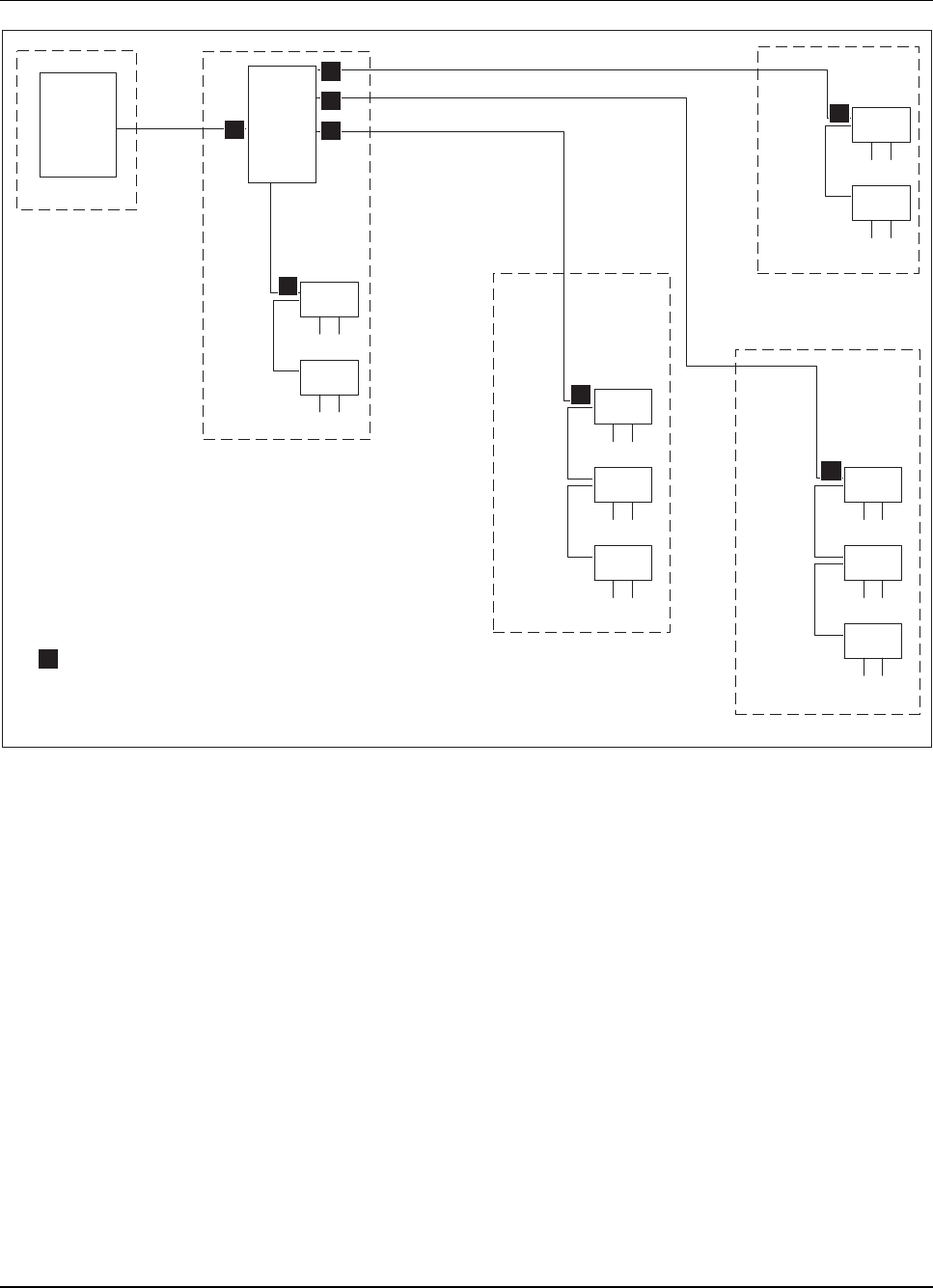
RBS 884 Pico (1900 MHz) CRI Installation
RH
RH
RH
RH
RH
RH
RH
RH
Pico
CRI
MSC
Link Group 1
Link Group 2
Link Group 4
Link Group 3
Leased T1/E1
Leased T1/E1
Leased T1/E1
T1/E1
Non-
Leased
Non-
Leased
Non-
Leased Non-
Leased
Non-
Leased
Leased
CRI Control and Radio Interface
MSC Mobile Switching Center
RH Radio Head
RH
RH
Non-
Leased
Channel Service Unit
c
c
c
c
c
c
c
c
c
Figure 3-51. RBS 884 Pico (1900 MHz) Configuration Example 1 (Leased Lines)
3-66 1/1531-AE/LZB 119 3834 Uae Rev PA6 2001-04-04
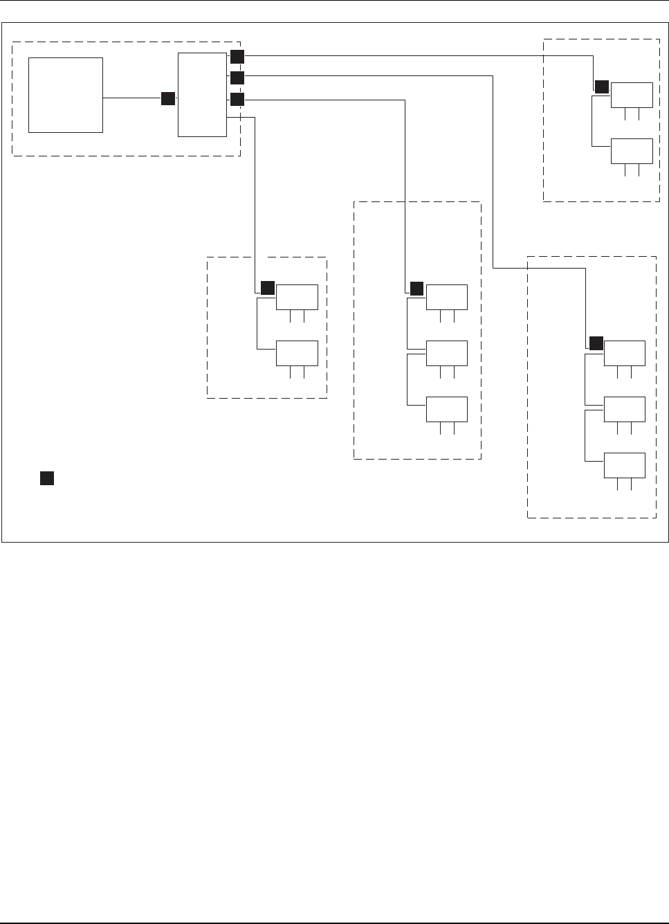
RBS 884 Pico (1900 MHz) CRI Installation
RH
RH
RH
RH
RH
RH
RH
RH
Pico
CRI
MSC
Location 1
Location 2
Location 3
Leased T1/E1
Leased T1/E1
Leased T1/E1
T1/E1
Non-
Leased Non-
Leased
Non-
Leased
Non-
Leased
Non-
Leased
Leased T1/E1
CRI Control and Radio Interface
MSC Mobile Switching Center
RH Radio Head
RH
RH
Location 4
Non-
Leased
Channel Service Unit
c
c
c
c
c
cc
c
c
Link Group 4
Link Group 3
Link Group 2
Link Group 1
Figure 3-52. RBS 884 Pico (1900 MHz) Configuration Example 2 (Leased Lines)
3. Ensure that the following cables and equipment are available:
•T1 100-ohm twisted-pair cable with connectors
•E1 120-ohm twisted-pair cable with connectors
•Wire/cable strippers and cutters
•Crimping tool
1/1531-AE/LZB 119 3834 Uae Rev PA6 2001-04-04 3-67

RBS 884 Pico (1900 MHz) CRI Installation
Radio Head to CRI Cabling
4.
DANGER!
Do not install T1/E1 PCM cable close to fluorescent light fixtures,
transformers, or electric motors. For cabling practices, see
“Commercial Building Standard for Telecommunications Pathways
and Spaces, EIA/TIA-569.”
If the CRI is remote and the line to the CRI is leased, install a Channel
Service Unit (CSU) and route a T1/E1 PCM cable from the CSU to the
first Radio Head (Radio Head 1). If the CRI is local and the line to
the CRI is proprietary or non-leased, route the cable directly from the
local CRI to Radio Head 1. Refer to Table 4-8 on page 4-35 for the
technical specifications for the PCM connections. See Figure 3-53
on page 3-69 and Figure 3-56 on page 3-74.
3-68 1/1531-AE/LZB 119 3834 Uae Rev PA6 2001-04-04
RBS 884 Pico (1900 MHz) CRI Installation
Radio
Head 1
SEC
SEC
PRI
PRI
PRI
PSTN
CRI with
ELI Unit
T1 100-ohm twisted-pair
or
E1 120-ohm twisted pair
Long-Haul
T1 or E1
Long-Haul
T1 or E1
Long-Haul
T1 or E1
Channel Service Unit
CRI Control and Radio Interface
ELI Enhanced Link Interface
PRI Primary Interface Connector
PSTN Public Switched Telephone Network
SEC Secondary Interface Connector
Leased
Network
Line
Leased
Network
Line
Radio
Head 2
Radio
Head 3
Link Group 1
c
c
c
Figure 3-53. T1/E1 PCM Cabling to Radio Heads
Table 3-9. PCM Connection Specifications
Type of Connection Specifications
Proprietary
non-leased line
800 to 1000 m with a maximum attenuation of 30 dB
T1/E1 Receiver sensitivity: -105 dBm (3% BER with diversity)
Clock: Stratum 2 or better
5. Follow good lab practices in labeling all cables.
1/1531-AE/LZB 119 3834 Uae Rev PA6 2001-04-04 3-69
RBS 884 Pico (1900 MHz) CRI Installation
6. Attach an RJ-45 connector to the T1/E1 PCM cable. Refer to Figure
3-54 on page 3-70 and Table 4-9 on page 4-36 for pinout information.
Note: Pin 1 is on the extreme left of the connector cable
opening, looking into the back of an RJ-45 connector
with the latch down.
PCM Cable
Quarter-Plug
Connector
PCM Cable
RJ-45 Connector
02
08
Quarter-Plug Connector
Cable View
A02
ABC
+
-
-
+
White/Blue
Blue
White/Orange
Orange
PCM IN
PCM OUT
}
}
C02
C04
C06
C08
<
<
<
<
>
>
>
>
2
1
4
5
CRI Control and Radio Interface
PCM Pulse Code Modulation
Figure 3-54. PCM Connector (100/120-ohm) Pinouts
Table 3-10. Pinouts for 100/120-ohm Twisted Pair Cable
Transmission
Recommended
Wire Color
RJ-45 Pin
Number
Quarter Pin
Number
White-blue 1C02PCM In
Blue-white 2C04
White-orange 4C06PCM Out
Orange-white 5C08
7. If using the CRI patch panel, route the PCM (CRI-RH) cable to the
back of the patch panel (see Figure 3-55 on page 3-71).
3-70 1/1531-AE/LZB 119 3834 Uae Rev PA6 2001-04-04
RBS 884 Pico (1900 MHz) CRI Installation
L1
L1 L3 L5 L7 L9 L11
L2 L4 L6 L8 L10
L2
L3
L4
L5
L6
L7
L8
L9
L10
L11
XLI
18
XLIXLI
19 20
Connect the CRI-RH cables
to the back of the patch panel
(L1, L2, L3, L4).
Figure 3-55. Connecting the CRI-RH Cable to the Patch Panel
8. Route a short PCM cable from the front of the patch panel to the front
of the ELI unit and attach appropriate connectors. Refer to Figure 3-54
on page 3-70 and Table 4-9 on page 4-36 for pinout information. Refer
to Figure 3-56 on page 3-74 for the ELI port locations.
9. If bypassing the patch panel, attach a quarter-plug connector to the
T1/E1 PCM cable and plug the cable into the connector port (position
B1, B2 or B3) on the front of the ELI unit. Refer to Figure 3-54 on
page 3-70 and Table 4-9 on page 4-36 for pinout information. Refer to
Figure 3-56 on page 3-74 for the ELI port locations.
PSTN to ETB Cabling
10. Loosen the screws on the forked tray below the CRI subrack.
1/1531-AE/LZB 119 3834 Uae Rev PA6 2001-04-04 3-71

RBS 884 Pico (1900 MHz) CRI Installation
11.
Warning!
The ETB cable must be grounded at each screen to make sure that the
ETB cable is grounded.
Refer to Figure 3-54 on page 3-70 for pinout information and route
the PCM (ETB)cable from the incoming network CSU to the ETB,
position B3.
12. If a second ETB cable is to be connected, connect it to position B3
in the second ETB (unit position number 6).
10.1.3 Leased E1 Installation (Coaxial Cable)
The following section provides installation information for network or leased
lines using E1 75-ohm coaxial cable.
Preparations
1. Ensure that the Radio Heads are properly installed and tested prior to
starting this installation procedure.
Note: The first or primary Radio Head in each link or link
group must be installed and connected to the PSTN.
Additional Radio Heads are installed after the initial
communication is established between the CRIand
the primary Radio Heads.
2. Determine the number of Radio Head link groups (usually determined
by the number of E1 links). Refer to Figure 3-51onpage3-66and
Figure 3-52 on page 3-67 for configuration examples.
Note: If the number of Radio Heads or Radio Head link
groups to be connected to the CRI is not known,
consult the next level of maintenance support or
the site engineer.
3. Ensure that the following equipment is available:
•E1 75-ohm coaxial cable with British Naval Connector (BNC)
fittings
•Wire/cable strippers and cutters
•Crimping tool
3-72 1/1531-AE/LZB 119 3834 Uae Rev PA6 2001-04-04

RBS 884 Pico (1900 MHz) CRI Installation
Radio Head to CRI Cabling
4.
DANGER!
Do not install T1/E1 PCM cable close to fluorescent light fixtures,
transformers, or electric motors. For cabling practices, see
“Commercial Building Standard for Telecommunications Pathways
and Spaces, EIA/TIA-569.”
Route the E1 (75-ohm coaxial) leased line to the CRI, allowing extra
cable for the CSU and the connectors.
Note: The use of PSTN leased lines requires a CSU to
receive or transmit signals to and from the PSTN.
Install a CSU between the CRI and the E1 network.
5. Install the CSU using the documentation supplied with the CSU.
6. Connect the 75-ohm coaxial cable from the CSU to the patch panel
or directly to the ELI unit positions 17–21, B3. See Figure 3-56 on
page 3-74.
1/1531-AE/LZB 119 3834 Uae Rev PA6 2001-04-04 3-73
RBS 884 Pico (1900 MHz) CRI Installation
ELI
18
ELI
17
EMRP
16
EMRP
15
EMRP
14
EMRP
13
EMRP
12
EMRP
11
EMRP
10
EMRP
9
EMRP
8
EMRP
7
ELIELI
19 20
ELI Enhanced Link Interface
EMRPS Extension Module Regional Processor
with Device Speech Bus Access
Note: The Pico system is delivered with one factory-installed ELI unit
that supports one T1/E1 link and a maximum of three Radio Heads.
The system is capable of accommodating four ELI units and
ten EMRPS units to support four T1/E1 links and ten Radio Heads.
T1
100
Ω
T1
100
Ω
T1
100
Ω
E1
120
Ω
E1
75
Ω
E1
75
Ω
E1
75
Ω
E1
120
Ω
E1
120
Ω
PCM Pulse Code Modulation
RS
232 RS
232 RS
232
T1
100
Ω
E1
120
Ω
E1
75
Ω
RS
232
ELI
18
ELI
17 ELI
19 ELI
20
PCM Link Monitoring
and Synchronization
Referencing
L1
L2
L3
L4
L5
L6
L7
L8
L9
L10
L11
Figure 3-56. ELI Unit and Connector Positions
7. If using a patch panel, route a short PCM cable from the front of
the patch panel to the front of the ELI unit and attach appropriate
connectors. Refer to Figure 3-54 on page 3-70 and Table 4-9 on page
4-36 for pinout information. Refer to Figure 3-56 on page 3-74 for the
port location on the ELI unit.
PSTN to ETB
8. Loosen the screws on the forked tray below the CRI subrack.
3-74 1/1531-AE/LZB 119 3834 Uae Rev PA6 2001-04-04

RBS 884 Pico (1900 MHz) CRI Installation
9.
Warning!
The ETB cable must be grounded at each screen to make sure that the
ETB cable is grounded.
Install the ETB cable from the incoming E1 network to position B4
on the ETB unit. Refer to Table 3-11 on page 3-75 for the cable
and pinout information.
Table 3-11. ETB (PCM) Cable for E1 75-ohm Coax Cable
Transmission Quarter Plug Pin No.
RX (PCM IN) B03
Shield C02, C04, A04
RX (PCM OUT) B07
Shield C06, C08, A06
10. Attach the ETB (PCM) cable on top of the ETB-ELI sync cable.
Note: The ETB-ELI sync cable is required for non-leased
or proprietary connections. The sync cable is not
required for T1/E1 leased connections, although its
presence does not interfere with leased connections.
11. If a second ETB cable is to be connected, connect it to position B4
in the second ETB (unit position number 6).
10.1.4 Non-Leased PCM Installation
The following section provides cable installation information for proprietary
or non-leased lines.
Preparations
1. Ensure that all Radio Heads are properly installed prior to starting this
installation procedure.
Note: For installation convenience, the CRI to Radio Head
cabling information is also included in Part 3, RBS
884 Pico (1900 MHz) CRI Installation.
1/1531-AE/LZB 119 3834 Uae Rev PA6 2001-04-04 3-75
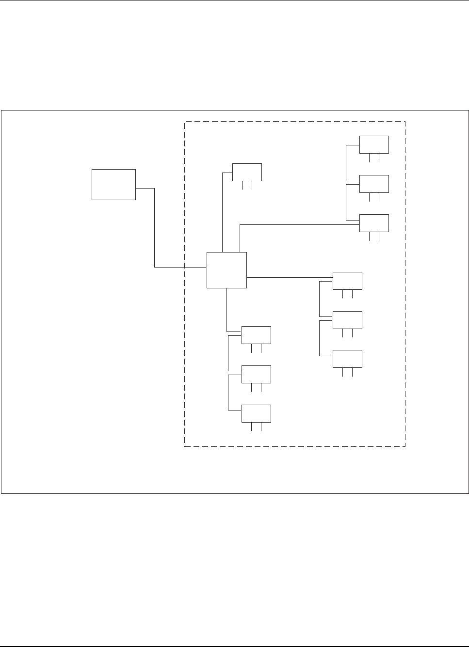
RBS 884 Pico (1900 MHz) CRI Installation
2. Determine the number of Radio Head link groups. Refer to Figure
3-57 on page 3-76 for a configuration example.
Note: If the number of Radio Heads or Radio Head link
groups to be connected to the CRI is not known,
consult the next level of maintenance support or
the site engineer.
RH
RH
RH
RH
RH
RH
PICO
CRI
RH
RH
RH
MSC
CRI Control and Radio Interface
MSC Mobile Switching Center
RH Radio Head
Leased T1/E1
Non-
Leased
Non-
Leased
Non-
Leased
Non-
Leased
Non-
Leased
Non-
Leased
Non-
Leased
Non-
Leased
Non-
Leased
RH
Non-
Leased
Link Group 4
Link Group 3
Link Group 2
Link Group 1
Figure 3-57. RBS 884 Pico (1900 MHz) with Proprietary Configuration Options
3-76 1/1531-AE/LZB 119 3834 Uae Rev PA6 2001-04-04

RBS 884 Pico (1900 MHz) CRI Installation
CRI to Radio Head
3.
DANGER!
Do not install T1/E1 PCM cable close to fluorescent light fixtures,
transformers, or electric motors. For cabling practices, see
“Commercial Building Standard for Telecommunications Pathways
and Spaces, EIA/TIA-569.”
Run a proprietary (non-leased) T1/E1 PCM cable from the ELI unit
(position 17) in the CRI or from the patch panel to the first Radio
Head. The first Radio Head refers to the Radio Head closest to the
CRI. The allowable cable length is 800 to 1000 m with a maximum
attenuation of 30 dB.
4. Attach an RJ-45 connector to the Radio Head end of the cable and a
quarter-plug connector (for ELI) or RJ-45 connector (for patch panel)
to the CRI end. Refer to Figure 3-54 on page 3-70.
Note: Pin 1 is on the extreme left of the connector cable
opening, looking into the back of an RJ-45 connector
with the latch down.
1/1531-AE/LZB 119 3834 Uae Rev PA6 2001-04-04 3-77
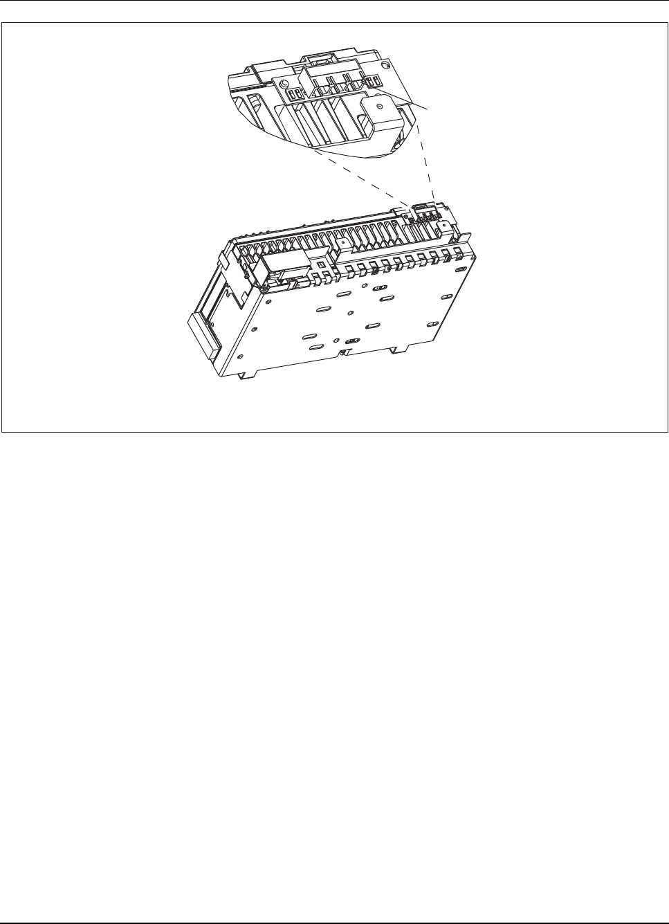
RBS 884 Pico (1900 MHz) CRI Installation
Primary PCM
Interface
Connector Port
Rear View of Radio Head
PCM Pulse Code Modulation
Figure 3-58. Location of Radio Head PCM Interface Connector Ports
5. Connect one end of the cable to the Primary (PRI) PCM interface
connector on the top of the first Radio Head in Link Group 1 (see
Figure 3-58 on page 3-78 and Figure 3-57 on page 3-76).
6. Run the other end of the cable to the CRI patch panel or directly to
the ELI unit position 17, B1/B2.
7. If a second PCM cable is to connected, connect one end of the cable
to the Primary (PRI) PCM interface connector on the top of the first
RadioHeadinLinkGroup2(seeFigure3-58onpage3-78andFigure
3-57 on page 3-76) and the other end to the to the second ELI unit
position 18, B1/B2, or to the CRI patch panel.
8. If a third PCM cable is to be connected, connect one end of the cable
to the Primary (PRI) PCM interface connector on the top of the first
RadioHeadinLinkGr
oup 3 (see Figure 3-58 on page 3-78 and Figure
3-57 on page 3-76) and the other end to the to the second ELI unit
position 19, B1/B2, or to the CRI patch panel.
9. If a fourth PCM cable is to be connected, connect one end of the cable
to the Primary (PRI) PCM interface connector on the top of the first
RadioHeadinLinkGroup4(seeFigure3-57onpage3-76andFigure
3-78 1/1531-AE/LZB 119 3834 Uae Rev PA6 2001-04-04

RBS 884 Pico (1900 MHz) CRI Installation
3-58 on page 3-78) and the other end to the second ELI unit position
20, B1/B2, or to the CRI patch panel.
10. If the patch panel is used, route a short PCM cable from the front of
the patch panel to the front of the ELI unit and attach appropriate
connectors. Refer to Figure 3-54 on page 3-70 and Table 4-9 on page
4-36 for pinout information. Refer to Figure 3-56 on page 3-74 for
the ELI port locations.
Note: If the patch panel positions are not known, consult
the next level of maintenance support or the site
engineer. Software and hardware assignments are
described in Part 4, Integration and Test.
Network to CRI Cable
11. Ensure that the following tools and materials are available prior to
starting this installation procedure:
•T1/E1 Cable (see Section 7.2 on page 3-13)
•Flat-blade screwdriver
12. Loosen the screws on the forked tray below the CRI subrack.
13.
Warning!
The ETB (PCM) cable must be grounded at each screen to assure
that the ETB cable is grounded.
Install the ETB cable. Connect to B3 (T1, 100-ohm), B3 (E1,
120-ohm), or B4 (E1, 75-ohm). The ETB (PCM) cable is installed on
top of the sync cable. Refer to Figure 3-59 on page 3-80 and Table
3-12 on page 3-80 for pinout information.
1/1531-AE/LZB 119 3834 Uae Rev PA6 2001-04-04 3-79
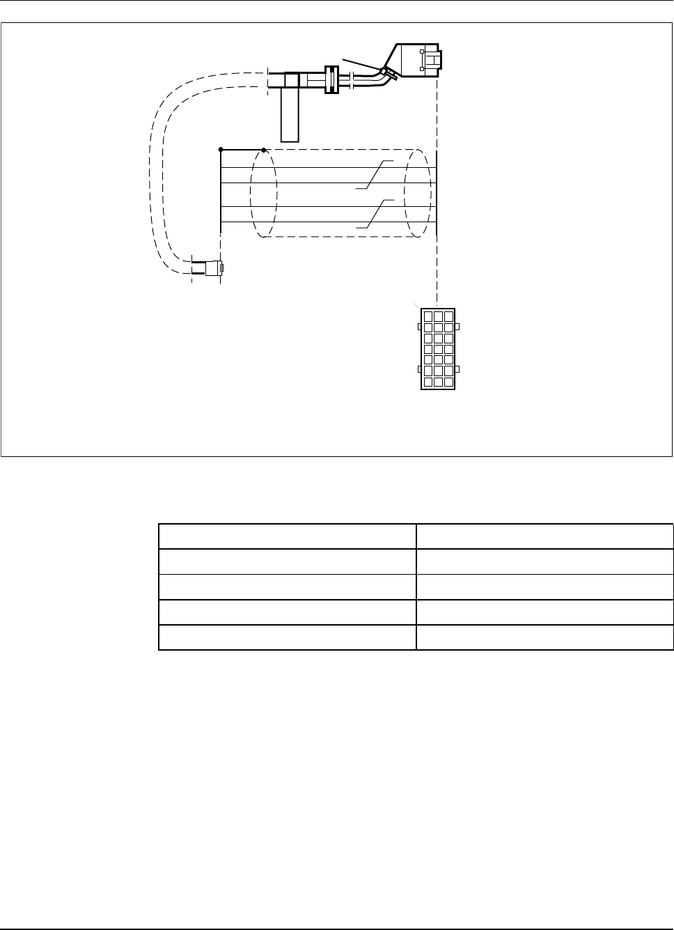
RBS 884 Pico (1900 MHz) CRI Installation
PCM Cable
Quarter-Plug
Connector
PCM Cable
RJ-45 Connector
02
08
Quarter-Plug Connector
Cable View
A02
ABC
+
-
-
+
White/Blue
Blue
White/Orange
Orange
PCM IN
PCM OUT
}
}
C02
C04
C06
C08
<
<
<
<
>
>
>
>
2
1
4
5
CRI Control and Radio Interface
PCM Pulse Code Modulation
Figure 3-59. Pinout Connections for 100/120-ohm Screened, Twisted pair Cable
Table 3-12. ETB (PCM) Cable for E1 75-ohm Coax Cable
Transmission Quarter-Plug Pin No.
RX (PCM IN) B03
Shield C02, C04, A04
TX (PCM OUT) B07
Shield C06, C08, A06
14. If a second ETB cable is to be connected, connect it to position B3
(100/120-ohm) or B4 (75-ohm) in the second ETB (unit position
number 6).
10.2 Defining Data Translations
1. Define data translations for the EMRPS units, assign software, and
define equipment. See Part 5, Integration and Test.
2. Create semi-permanent connections from the EMRPS units to the
ELI unit(s) for the control links.
3-80 1/1531-AE/LZB 119 3834 Uae Rev PA6 2001-04-04

RBS 884 Pico (1900 MHz) CRI Installation
3. Create semi-permanent connections from the ETB unit(s) to the ELI
unit(s) for the voice paths.
10.3 Equipment Start-up
Warning!
Applying power to the RBS improperly or in the wrong sequence can
damage equipment! Follow the procedures in this document to ensure that
the system is properly powered up.
Prerequisites
1. Ensure that the following activities have been completed prior to
power up of the RBS 884 Pico (1900 MHz):
•CRI cabinet installed and grounded
•All cables terminated
•All Radio Heads installed
•If used, patch antennas installed
•If used, external antennas installed
Apply Power
2. Connect the AC power cable to the AC outlet.
3. Turn the DC/DC converter units to the ON position. See Figure 3-60
on page 3-82 for the location of the DC converter units.
1/1531-AE/LZB 119 3834 Uae Rev PA6 2001-04-04 3-81
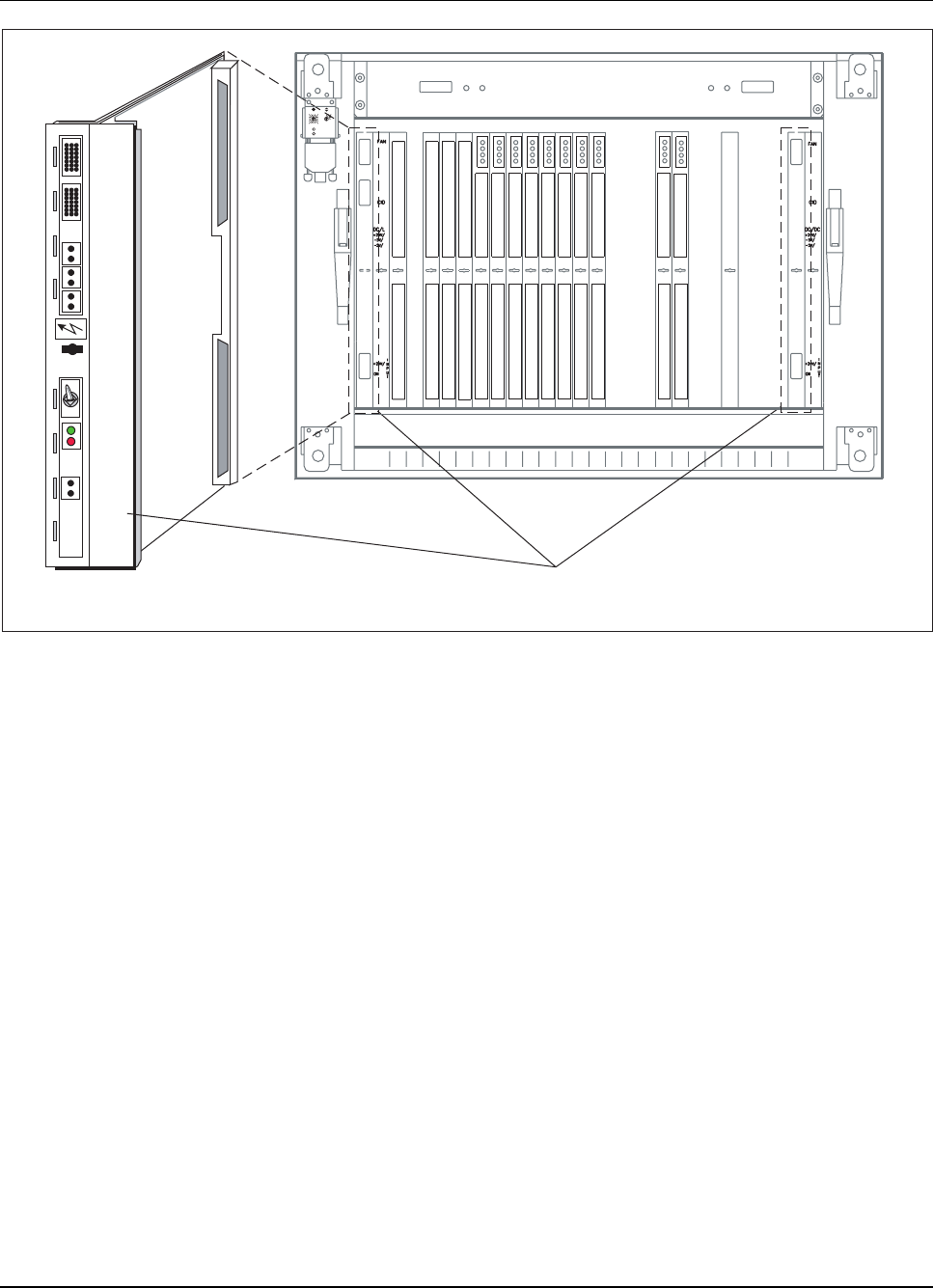
RBS 884 Pico (1900 MHz) CRI Installation
DCDC
Fan CID
0v
+24v
0v
+5v
0v
-5v
DC/DC
Converter
+24v/+5v/-5v
Input
0v
+24v
Error
Power
Off
On
Test
DC/DC Converter Unit
01 2
3
4
5
678910
11
12
13
14 15 AB C
D
E
Power
Error
DC/DC
1 STR
2 STR
3 ETB
5 ETB
6
EMRPS
8
EMRPS
9
EMRPS
10
EMRPS EMRPS EMRPS E
MRPS EMRPS E
MRPS EMRPS
EMRPS
11 12 13 14
15
16 17 18
DC/DC
23
ELI ELI ELI
19 20 21
Figure 3-60. DC/DC Converter Units
Notify the MSC
4. Notify the MSC operator that the CRI and Radio Head have been
installed. Software must be loaded at the MSC before the self-test
is performed.
Check LEDs
5. Verify that all LEDs light briefly during the self-test. If the CRI Error
LED remains ON steady red, refer to Part 6, Troubleshooting,fora
description of the LEDs and recommended troubleshooting solutions.
6. Check the TRX LEDs on the Radio Head. The TRX LEDs are located
immediately above the user interface display.
7. Check the Power/Fault LED on the lower-left corner of the Radio Head.
3-82 1/1531-AE/LZB 119 3834 Uae Rev PA6 2001-04-04

RBS 884 Pico (1900 MHz) CRI Installation
Check the Radio Heads
8. Wait 30 minutes to allow the PLL software in the Radio Heads to lock.
Note: Note: Under normal circumstances the PLL will lock
in less than 30 minutes. In some cases (with wander
frequencies of 0.03 Hz or less) the PLL will lock in
less than 30 minutes but the display will take more
than 30 minutes to indicate lock. In extremely rare
cases (with wander of 0.001 Hz at 138 UI) the PLL
may take more than 30 minutes to lock.
9. Check the Radio Head user interface display for alarms. If no
alarms are present, OK appears on the display. Refer to Part 7,
Troubleshooting, for further information about troubleshooting Radio
Head connection problems.
10. If using CSUs, consult the CSU customer documentation to
troubleshoot connection problems.
11. Check the TRX LEDs. Refer to Figure 3-61 on page 3-84 for the
location of the TRX LEDs. The TRX LEDs should be steady yellow,
indicating that the TRXs are deblocked and not carrying traffic.
Refer to Part 7, Troubleshooting, for further information about
troubleshooting TRX problems.
1/1531-AE/LZB 119 3834 Uae Rev PA6 2001-04-04 3-83
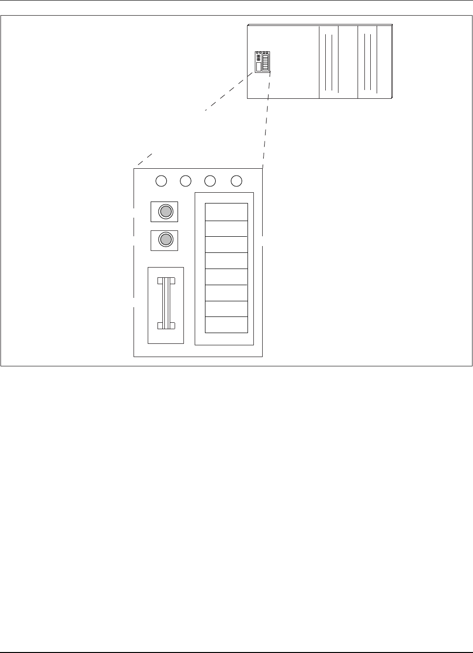
RBS 884 Pico (1900 MHz) CRI Installation
TRX 4 LED
TRX 3 LED
TRX 2 LED
TRX 1 LED
DISPLAY
Radio Head without Cover
SCROLL Button
SELECT Button
Factory Service
Port
Alphanumeric Display
Figure 3-61. Radio Head User Interface
12. Check the Power/Fault LED on the lower-left corner of the Radio Head.
Install Radio Head Cover
13. Use the four tamper-resistant screws provided to install the Radio Head
cover on the Radio Head. See Figure 3-62 on page 3-85. Use the Torx
driver tool supplied in the Radio Head Hardware Kit (NTM 201 1581).
3-84 1/1531-AE/LZB 119 3834 Uae Rev PA6 2001-04-04
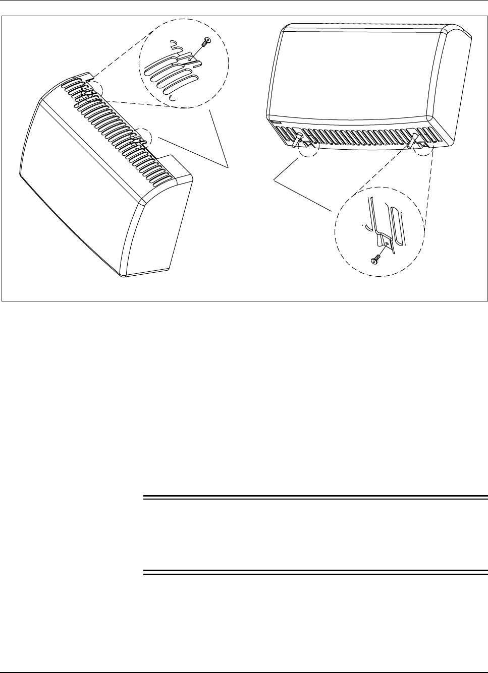
RBS 884 Pico (1900 MHz) CRI Installation
Top View Bottom View
Tamper-
Resistant
Screws
Figure 3-62. Installing Radio Head Cover
14. Install a raceway on all exposed cords and cables to prevent damage
or abrasion.
10.4 Completing CRI Installation
Secure Cables
1. Secure the cables in the vertical cable shafts with tie wraps.
2.
Warning!
Improper cutting of the cable ties may leave sharp edges. Make
sure that no rough edge remains and the cable tie end is flush with
the cable tie knot.
Use the cable tie gun to tighten and cut off the excess tie. If possible,
place the cable tie knot at the rear side of the cables.
1/1531-AE/LZB 119 3834 Uae Rev PA6 2001-04-04 3-85
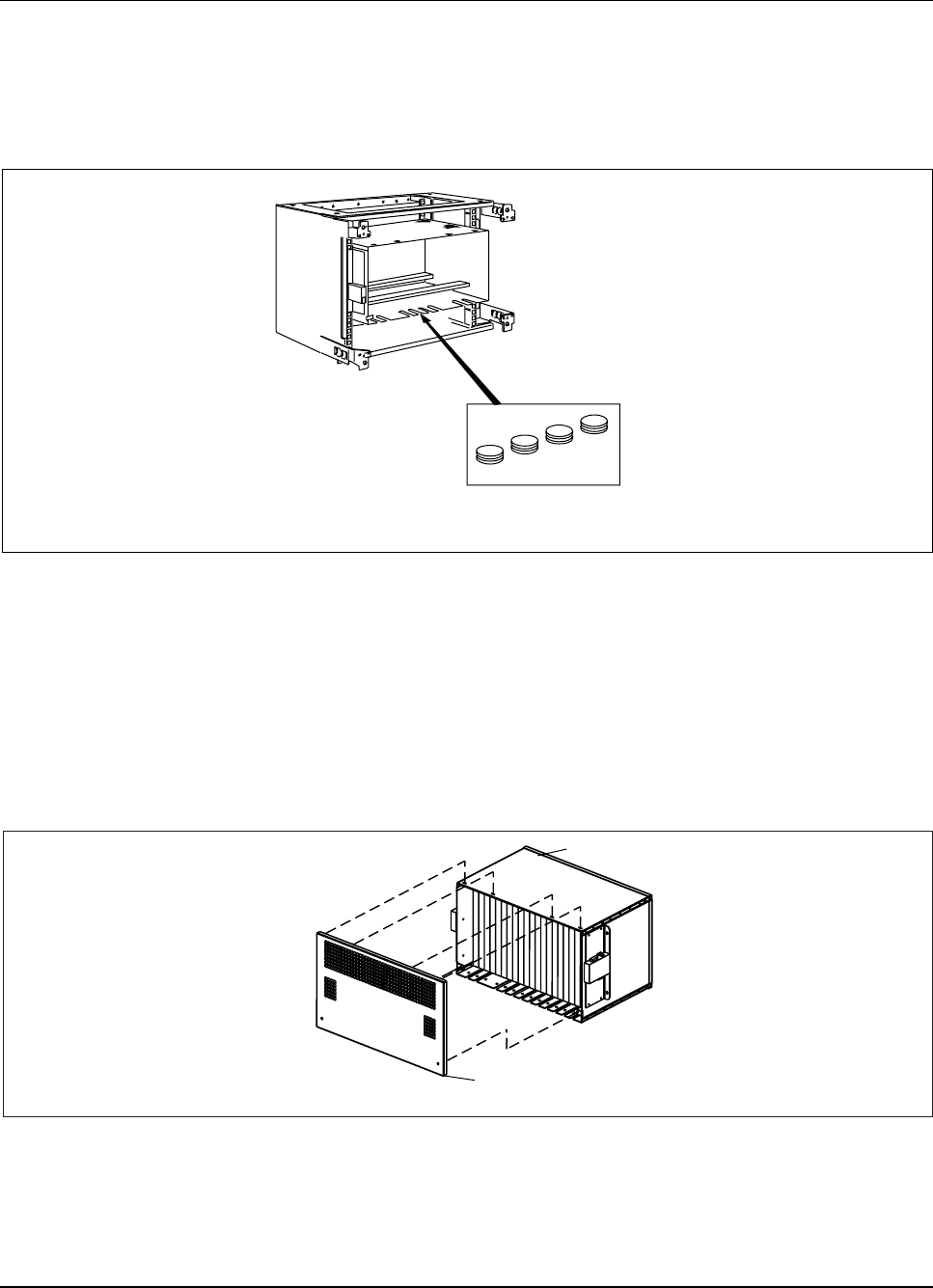
RBS 884 Pico (1900 MHz) CRI Installation
3. Insert EMC protection blanks into the ground slots in the CRI cabinet.
See Figure 3-63 on page 3-86.
Note: Fill the slots completely with blanks (that is, four
pieces including the cable metal collars).
EMC Protection
Blanks
CRI Cabinet
Figure 3-63. Inserting EMC Protection Blanks
4. Tighten the cable retaining screws.
Complete Rack Mount Installation
5. Install the EMI cover (SXK 107 4001/1) on the CRI subrack. See
Figure 3-64 on page 3-86.
EMI Cover
(SXK 107 4001/1)
CRI Magazine
Figure 3-64. EMI Cover Installation
3-86 1/1531-AE/LZB 119 3834 Uae Rev PA6 2001-04-04
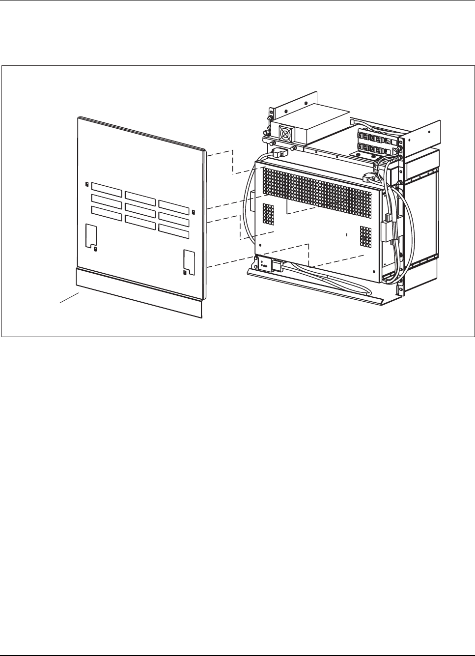
RBS 884 Pico (1900 MHz) CRI Installation
6. Place the door on the front of the CRI cabinet to complete the CRI
Rack Mount installation. See Figure 3-65 on page 3-87 for a view of
the CRI Rack Mount cover positions.
CRI Front Cover
(SXK 107 3761/2)
CRI Rack Mount
Figure 3-65. CRI Front Cover Installation
7. Notify the MSC operator that the installation is complete.
Complete Floor Mount Installation
8. Install the EMI cover (SXK 107 4001/1) on the CRI magazine (Figure
3-64 on page 3-86).
9. Usetwoscrewsforeachsidetoattachtherightandleftsidecovers
(NTM 201 674/1) to the CRI cabinet assembly (Figure 3-66 on
page 3-88).
1/1531-AE/LZB 119 3834 Uae Rev PA6 2001-04-04 3-87
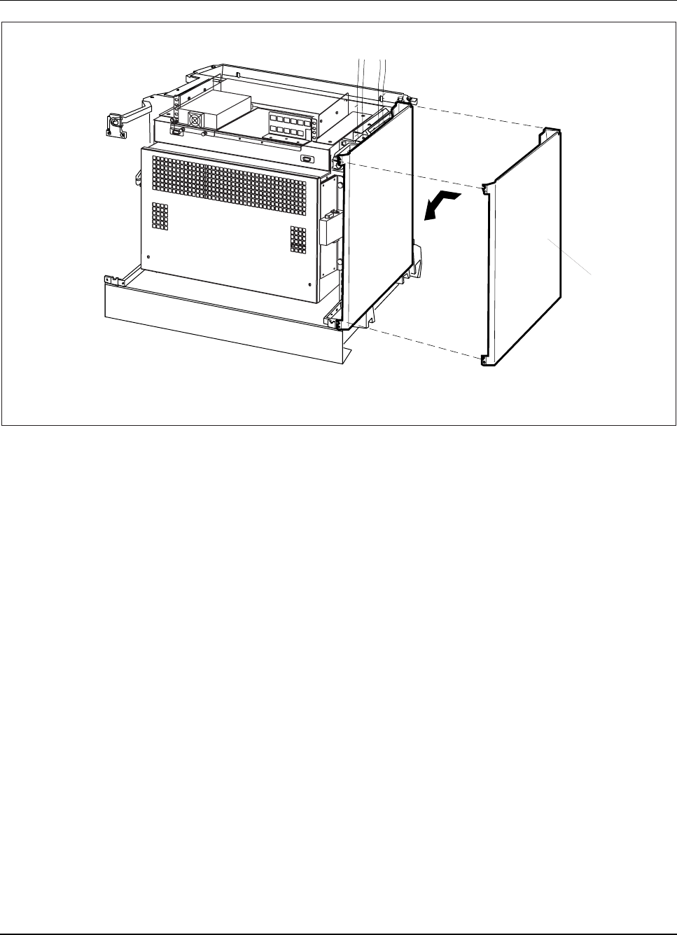
RBS 884 Pico (1900 MHz) CRI Installation
CRI Cabinet
Side
cover
Figure 3-66. CRI Side Cover Installation
10. Use two Torx (TX 20) screws to attach the right and left side covers
on the CRI base.
11. Use four Torx (TX 20) screws to attach the rear covers on the CRI base.
12. Slide the top cover (SXA 120 6893/1) onto the two rear bolts on the
power shelf. See Figure 3-67 on page 3-89.
3-88 1/1531-AE/LZB 119 3834 Uae Rev PA6 2001-04-04
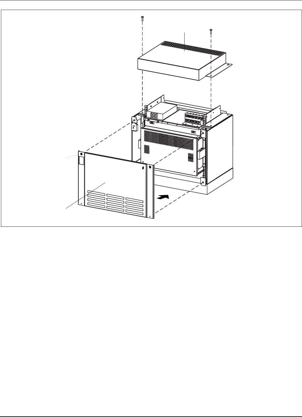
RBS 884 Pico (1900 MHz) CRI Installation
CRI Top Cover
(SXA 120 6893/1)
CRI Door
Snap Screw
(SXK 107 3761/2)
CRI Floor Mount
ERICSSON
RBS 884
c
c
Figure 3-67. CRI Top Cover and Door Installation
13. Install the two front bolts on the top cover. See Figure 3-67 on page
3-89.
14. Tighten the two rear bolts on the top cover.
15. Place the door (SXK 107 3761/2) on the front of the CRI cabinet to
complete the CRI floor mount installation. See Figure 3-67 on page
3-89.
16. Notify the MSC operator that the installation is complete.
1/1531-AE/LZB 119 3834 Uae Rev PA6 2001-04-04 3-89

RBS 884 Pico (1900 MHz) CRI Installation
3-90 1/1531-AE/LZB 119 3834 Uae Rev PA6 2001-04-04

Part 4
RBS 884 Pico (1900 MHz) Radio Head Installation
1 Introduction . . . . . . . . . . . . . . . . . . 4-3
2 SafetyPrecautions ............... 4-3
2.1 VoltageHazards ............. 4-3
2.2 Electrostatic Discharge (ESD) . . . . . . . 4-4
3 GeneralInformation ............... 4-4
4 Unpacking ................... 4-4
4.1 Tools .................. 4-5
4.2 WarrantyNotification ........... 4-5
5 SiteSelectionandPreparation ......... 4-5
5.1 SelectingaLocation ........... 4-5
5.2 Preparing an Installation Location . . . . . 4-7
6 PrerequisitesandTools ............. 4-8
6.1 Prerequisites ............... 4-8
6.2 T1/E1Requirements ........... 4-8
6.3 ToolsandMaterials ............ 4-8
7 RadioHeadSet-up ............... 4-9
7.1 Radio Head Configuration Procedure . . . . 4-10
7.2 Radio Head DIP Switches (E1 Only) . . . . 4-24
8 EquipmentInstallation ............. 4-25
8.1 Radio Head Installation . . . . . . . . . . 4-25
8.2 AntennaInstallation ............ 4-30
8.3 Cable Installation and Power-Up . . . . . . 4-33
2/1531-AE/LZB 119 3834 Uae Rev PA6 2001-04-04 4-1

RBS 884 Pico (1900 MHz) Radio Head Installation
4-2 2/1531-AE/LZB 119 3834 Uae Rev PA6 2001-04-04

RBS 884 Pico (1900 MHz) Radio Head Installation
1 Introduction
This document contains step-by-step procedures for installing and cabling
the Radio Head for the RBS 884 Pico (1900 MHz) system. The quantity,
location, and configuration of the Radio Heads in the RBS 884 Pico are
based on the Radio Frequency (RF) engineering requirements and the
required operating capacity of the system.
2 Safety Precautions
Before starting any installation, test, or maintenance procedures, review the
safety regulations provided in this section and any other applicable parts
of this manual. Additionally, the installer is responsible for determining
that the installation conforms to all applicable electrical, mechanical,
communications, and construction codes.
Carefully review each procedure before starting, including the
admonishments (dangers, warnings, and cautions) that are applicable to
the procedure.
2.1 Voltage Hazards
DANGER!
Hazardous voltages over 100 V are used in the operation of this equipment.
Observe safety precautions. Use extreme caution when working on powered
up equipment. Do not be misled by the term “Low Voltage.”Contact with
AC power of any voltage can cause injury and sometimes death.
Always observe the following:
•Remove all jewelry before working on the equipment.
•Do not touch high voltage connections when installing or operating
the equipment.
•Disconnect the power before working on the equipment.
•If possible, keep one hand away from the equipment to reduce the
possibility of current flowing through vital body organs.
2/1531-AE/LZB 119 3834 Uae Rev PA6 2001-04-04 4-3

RBS 884 Pico (1900 MHz) Radio Head Installation
2.2 Electrostatic Discharge (ESD)
The human body acquires static charge in all situations involving movement
(for example, when handling plastic parts).
If any part of the human body comes in contact with a grounded Integrated
Circuit (IC) component, the static charge can cause an electrostatic discharge,
resulting in a spark and damage to the component.
Always observe the following:
•Follow the instructions for handling sensitive electronic components
and printed circuit boards to avoid component damage caused by
ESD.
•When working with components and printed circuit boards, use an
ESD wrist strap to avoid ESD damage.
3 General Information
Complete the following instructions before starting the installation:
•Compare all boxes or transportation crates with the bill of lading
(also called a packing slip), and ensure all items are received.
•Inventory all items.
•Note any damage or discrepancies, and notify your logistics
coordinator.
4 Unpacking
The RBS 884 Pico (1900 MHz) Radio Head equipment is packaged in a
shipping box that contains the following items:
•Accessory box
The accessory box contains the Radio Head cover, the Radio Head
mounting bracket, a hardware kit, and the installation instructions.
•Radio Head
4-4 2/1531-AE/LZB 119 3834 Uae Rev PA6 2001-04-04

RBS 884 Pico (1900 MHz) Radio Head Installation
The Radio Head can be unpacked after the accessory box has been
removed from the shipping box.
•Optional Patch Antenna
If ordered, the optional patch antenna is shipped in a separate box.
Note: One EMRPS kit, consisting of an EMRPS unit, cable, and
address plugs, is shipped for each Radio Head.
4.1 Tools
A pair of cutters is recommended for cutting the transport straps, and a knife
is recommended for cutting the bags.
4.2 Warranty Notification
Warning!
Do not tamper with the Warranty Seal on the Radio Head. Tampering with
this seal voids your warranty. The Radio Head does not contain field
serviceable components. Service should only be performed by your local
Ericsson repair center.
5 Site Selection and Preparation
Specific site selection and preparation guidelines for the RBS Pico (1900
MHz) Radio Head are provided in this section. Verify that all site selection
and preparation requirements in this section have been met before starting
the installation.
The maximum pico cell radius is approximately 30 to 50 m (98 to 164 ft)
or an approximate area of 2,826 to 7,854 sq m (30,170 to 84,500 sq ft)
depending on the propagation conditions.
5.1 Selecting a Location
Use the following guidelines to select an installation location:
2/1531-AE/LZB 119 3834 Uae Rev PA6 2001-04-04 4-5

RBS 884 Pico (1900 MHz) Radio Head Installation
•Select an indoor wall. The RBS 884 Pico (1900 MHz) Radio
Heads can be mounted on both external and internal walls within
an enclosed structure.
•Select a location that is within 1 to 1.5 meters (3 to 5 ft) of a
dedicated AC power outlet. Do not use an extension cord or an outlet
that contains other power cords.
•Select a location where the AC power outlet is easily accessible.
Note: The AC power outlet serves as the safety power-disconnect point
for the Radio Head.
•Select a location free from traffic and equipment. It is important that
the Radio Heads are not located in an area where equipment and
people can bump into or damage the Radio Heads.
•Select a location that meets the operating environment and clearance
requirements in Section 5.1.1 on page 4-6 and Section 5.1.2 on
page 4-6.
5.1.1 Operating Environment
The Radio Head indoor operating environment must meet the following
requirements:
•Air temperature of 5 to 45 C
•Humidity between 10% to 90%, noncondensing
Note: Refer to Part 2, System Description for a complete list of the
Radio Head technical specifications.
5.1.2 Clearance Specifications
The Radio Head wall mount location must meet the following minimum
clearance specifications for effective cooling of the Radio Head:
•Unobstructed area 23 cm (9 in) from the top of the mounting bracket
to the ceiling
•Unobstructed area 30 cm (12 in) below the mounting bracket
•Unobstructed area 30 cm (12 in) on the left side and the right side of
the mounting bracket
•Minimum separation distance for patch and monopole antennas
20 cm (8 in) from all persons.
4-6 2/1531-AE/LZB 119 3834 Uae Rev PA6 2001-04-04
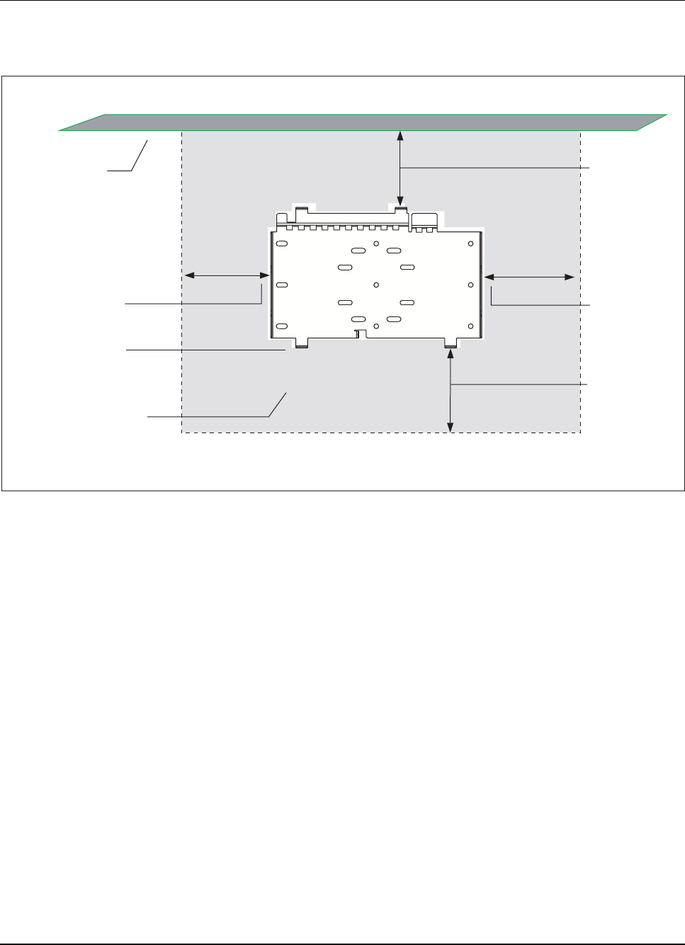
RBS 884 Pico (1900 MHz) Radio Head Installation
The minimum clearances for the Radio Head are shown in Figure 4-1 on
page 4-7.
Front View
of Mounting Bracket
Ceiling 23 cm
(9 in)
Bottom of
Mounting Bracket
Obstruction-Free Area
(Shaded Area)
30 cm
(12 in) 30 cm
(12 in)
30 cm
(12 in)
Figure 4-1. Mounting Bracket Clearance Specifications
To comply with FCC RF exposure requirements, the external antennas used
with this device must be mounted to provide a minimum separation distance
of 20cm (8 inches) from all persons, with the antenna gain not exceeding 14
dBi. Amplifiers and boosters are not permitted.
5.2 Preparing an Installation Location
Determine if a dedicated AC power outlet is located within 1.5 m (5 ft) of
the planned Radio Head installation. If necessary, install a dedicated AC
power outlet near the planned Radio Head location.
2/1531-AE/LZB 119 3834 Uae Rev PA6 2001-04-04 4-7

RBS 884 Pico (1900 MHz) Radio Head Installation
6 Prerequisites and Tools
6.1 Prerequisites
All appropriate mounting hardware (bolts, clamps or screws) must be
available for the designated location for securing the mounting bracket (dry
wall, brick, masonry, or a steel girder). Refer to the local building practices
for information on appropriate mounting hardware.
The mounting hardware must support a minimum of 16 kg (35 lb) and meet
any local seismic requirments. Use a minimum of four mounting points.
For example, use a minimum of four, 3/8-inch (0.8 cm) diameter bolts to
distribute the weight of the Radio Head evenly between the bolts.
The T1 cable must be plenum rated, Category 5 (CAT 5), 24-gauge
unshielded, twisted-pair (UTP) cable. The E1 cable may either be 75-ohm
coaxial or 120-ohm twisted pair (TP) cable. The allowable cable length is
800 to 1000 m with a maximum attenuation of 30 dB.
6.2 T1/E1 Requirements
The T1/E1 connection must meet the following requirements:
•MSC Connection
–ANSI T1: 1.544 Mbit/s
–ANSE E1: 2.048 Mbit/s
•Delay: 5 ms maximum
•Clock: Stratum 2 or better
6.3 Tools and Materials
The tools shown in Table 4-1 on page 4-9 are required for installing a RBS
884 Pico (1900 MHz) Radio Head:
4-8 2/1531-AE/LZB 119 3834 Uae Rev PA6 2001-04-04

RBS 884 Pico (1900 MHz) Radio Head Installation
Table 4-1. Tools for Installing Radio Head
Product Number Description
NTM 201 1581 Hardware Kit
N/A Crimping tool
LZY 250 01/14 ESD Wrist Strap and Cable
N/A Open-end wrench set
N/A Small flat-head screwdriver
N/A Small plastic stylus to depress
customer interface buttons
7 Radio Head Set-up
The Pico Radio Head customer interface has an eight-character alphanumeric
display and two push buttons, SCROLL and SELECT. The customer
interface is used to view the current alarms and to configure the Radio
Head. Refer to Figure 4-2 on page 4-10 for the location of the Radio Head
customer interface.
2/1531-AE/LZB 119 3834 Uae Rev PA6 2001-04-04 4-9

RBS 884 Pico (1900 MHz) Radio Head Installation
TRX 4 LED
TRX 3 LED
TRX 2 LED
TRX 1 LED
DISPLAY
Radio Head without Cover
SCROLL Button
SELECT Button
Factory Service
Port
Alphanumeric Display
Figure 4-2. Radio Head Customer Interface
Use the SCROLL button to sequentially review all menu items. Use the
SELECT button to select the displayed menu item or to activate a submenu.
Note: The current parameters are enclosed in brackets. An asterisk, *,
appears next to parameters that have been selected, but not
enabled.
7.1 Radio Head Configuration Procedure
Preparation
1. Ensure that the following tools and materials are available prior to
starting this configuration procedure:
4-10 2/1531-AE/LZB 119 3834 Uae Rev PA6 2001-04-04

RBS 884 Pico (1900 MHz) Radio Head Installation
•Plastic stylus or other suitable tool to depress the Radio Head
customer interface buttons
•Suitable work area with AC power outlet
2. Refer to the site-specific configuration plans, and position the Radio
Heads on the floor (or a suitable work area) directly below the planned
installation location. Make sure that the alphanumeric display and
interface buttons are easily accessible.
Note: A maximum of three Radio Heads can be installed
with one T1/E1 link.
3.
Warning!
Contact the MSC for authority to proceed before configuring the Radio
Head. The dual TRX units (four TRX devices) in the Radio Head must
be blocked before starting this procedure.
Connect the AC power cord to the AC receptacle on the Radio Head.
Insert the AC power cord plug into the AC outlet. See Figure4-3on
page 4-12 for the location of the AC power cord and AC receptacle.
Note: The supplied AC power cord is a 110 Vac power
cord for use in the US market only. If outside
of the US market, locate a power cord with the
appropriate power plug that meets local government
requirements. Make sure that the power cord has the
same rating, gauge, and type as the supplied power
cord (TSR 952 160/001).
2/1531-AE/LZB 119 3834 Uae Rev PA6 2001-04-04 4-11
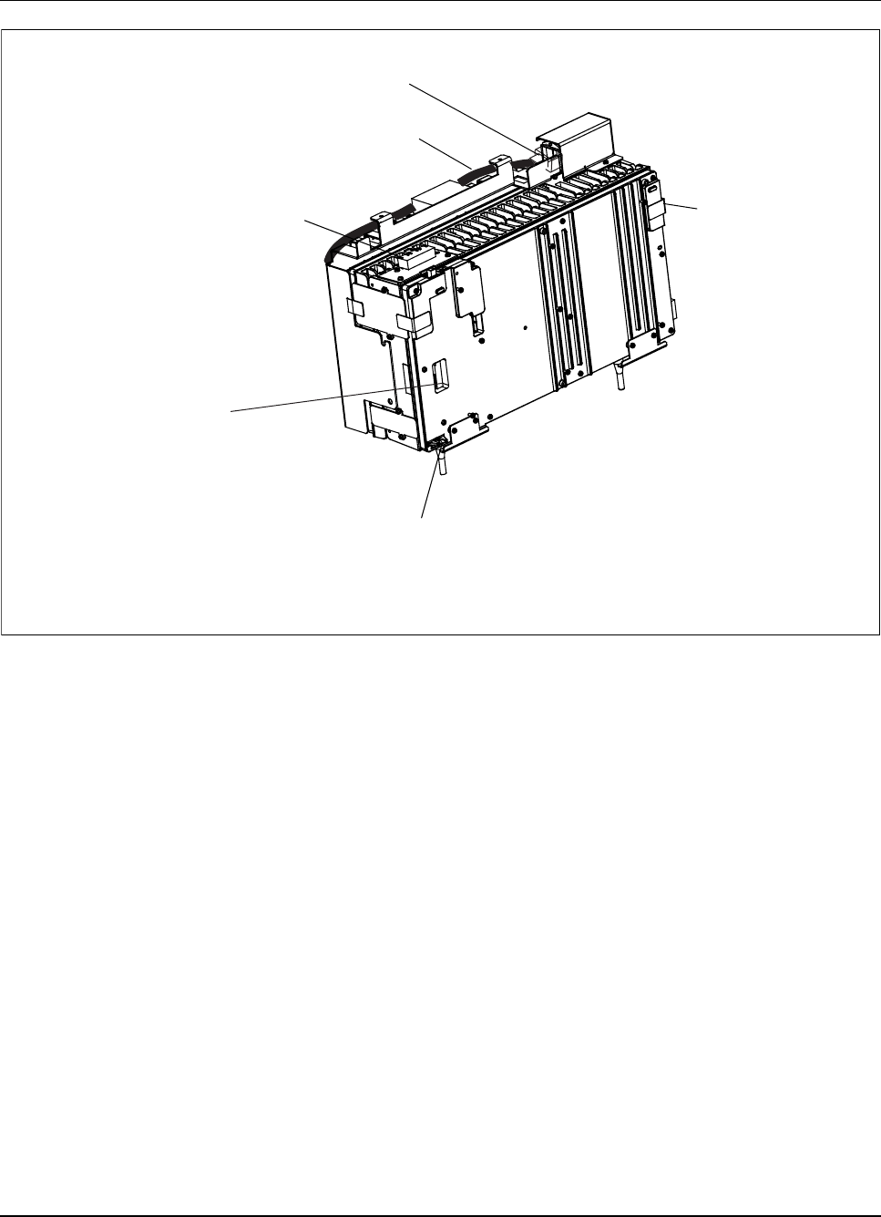
RBS 884 Pico (1900 MHz) Radio Head Installation
PCM Interface
Connnector Ports
RHI Customer
Interface
AC Alternating Current
LED Light Emitting Diode
PCM Pulse Code Modulation
RHI Radio Head Interface
Front View
Power/Fault LED
AC Receptacle
AC Power Cord
Tamper-Resistant
Seal
Figure 4-3. Radio Head AC Power Cord and AC Receptacle
Locating User Interface
4. Locate the SCROLL and SELECT buttons on the Radio Head user
interface. See Figure 4-2 on page 4-10 for the location of the SCROLL
and SELECT buttons.
Note: The SCROLL button sequentially displays the
configuration menu items. The SELECT button
activates a submenu or selects the current menu
item or parameter.
5. A configuration banner with the current parameter settings scrolls
across the alphanumeric display, as shown in the following example:
4-12 2/1531-AE/LZB 119 3834 Uae Rev PA6 2001-04-04

RBS 884 Pico (1900 MHz) Radio Head Installation
HW Prod ROA 117-9253, Rev 1, SWRev R1A-1,
Freq 1900, Mode RHI, Link T1, PriHaul L:0 dB,
SecHaul L: 0dB, Cascade End NO, Cabid 0, Reset INT
Figure 4-4. Configuration Banner Example 1
6. Ignore any alarm messages that appear at this time. Information about
the alarm messages is provided in Part 7 Troubleshooting.
Overview of Radio Head Configuration Menu
7. Refer to Figure 4-5 on page 4-14 for a diagram of the Radio Head
Configuration Menu. All menu items are accessed sequentially in a
circular queue. Each submenu must be exited in order to return to
the configuration menu.
Note: The menu item numbers are dynamically reassigned.
Some menu item numbers may not be the same as
those in the following example.
2/1531-AE/LZB 119 3834 Uae Rev PA6 2001-04-04 4-13

RBS 884 Pico (1900 MHz) Radio Head Installation
2 HAUL
PRI_IF (Primary Interface)
SEC_IF (Secondary Interface)
PRI_IF
PrSH Primary Short Haul
SeLH Primary Long Haul SeSH Secondary Short Haul
SeLH Secondary Long Haul
PrSH
SeSH PrLH
SeLH
<35m
<65m
<95m
<125
<155
<185
<210
0dB
-7dB
-15dB
-22dB
SEC_IF
1 LINK
T1
E1
3 NTWK (Network)
ATT (AT&T spec. 138 UI)
BELL (Bellcore spec. 28 UI)
4 CASCAD (Cascade)
ENDY (End of cascade)
ENDN (Not end of cascade)
6 ERRORS
For Test Use Only 5 CABID
Cabinet Identifier
8 SAVE
Save settings to
nonvolatile memory
EXIT
Exit Configuration Menu
9 BOOT
Reboot Radio Head
Exit Configuration Menu
7 INFO
SWINFO
HW_GEN
PRODUC
HW_REV
TIM
DAC
Not all menu items may be present
due to parameter dependencies.
11
Link T1 only
1
Figure 4-5. Radio Head Configuration Menu
4-14 2/1531-AE/LZB 119 3834 Uae Rev PA6 2001-04-04

RBS 884 Pico (1900 MHz) Radio Head Installation
8. The factory default settings are as follows:
•Link Type = T1
•Primary Haul Type = Long Haul, 0 dB
•Secondary Haul Type = Long Haul, 0 dB
•Network PLL Specification = ATT
•Cascade Position = ENDN (not at the end)
•Cabinet ID Number = 0
Setting the Link Type
9. Press the SELECT button to exit the Alarm Status mode and access
the Configuration program. The first menu item, LINK, appears on
the display.
10. Press the SELECT button and T1 appears. The brackets reflect the
current setting.
Note: The current parameters are enclosed in brackets. An
asterisk, *, appears next to parameters that have been
selected, but not enabled.
11. Press the SELECT button to select the T1 parameter or press the
SCROLL button followed by the SELECT button to select the E1
parameter.
Note: Pressing the SELECT button a second time deselects
the parameter.
12. Press the SCROLL button followed by the SELECT button to exit the
Link Type option.
Table 4-2. Configuration Program –Link Menu
Menu Parameters Explanation Notes
[T1] 1.544 Mbps
transmission link
Specifies T1 link.
LINK
E1 2.048 Mbps
transmission link
Specifies E1 link.
2/1531-AE/LZB 119 3834 Uae Rev PA6 2001-04-04 4-15

RBS 884 Pico (1900 MHz) Radio Head Installation
Setting the Primary and Secondary Interface Haul Settings (LINK T1 only)
Warning!
Step 13 on page 4-16 to Step 24 on page 4-17 apply to the LINK T1
option only.
13. Press the SCROLL button until HAUL appears.
14. Press the SELECT button and PRI_IF (Primary Interface) appears.
15. Press the SELECT button and PrSH (Primary Short Haul) appears.
16. Press the SELECT button to display the first short haul line parameter
(<35m).
Note: The short haul line parameters are listed in meters.
See Appendix E for a metric conversion table.
17. Press the SELECT button to select <35m or press the SCROLL button
to cycle through the other short haul line parameters.
Note: Pressing the SELECT button a second time deselects
the parameter.
18. Press the SELECT button to select the appropriate short haul parameter.
Note: The length of the Radio Head cables must be
determined before the short haul parameters are set.
19. Press the SCROLL button until PrLH (Primary Long Haul) appears.
20. Press the SELECT button to display the first long haul line parameter
(0dB).
21. For non-leased connections, select the 0dB default parameter.
For leased connections, consult your CSU documentation for
recommended long haul line parameter settings.
Note: Determine the length of the T1 cables before
selecting the long haul line parameter.
22. Press the SELECT button to select the appropriate long haul parameter.
23. Press the SCROLL button until exit appears, and press the SELECT
button to exit the Primary Interface submenu.
4-16 2/1531-AE/LZB 119 3834 Uae Rev PA6 2001-04-04

RBS 884 Pico (1900 MHz) Radio Head Installation
24. Repeat Step 14 on page 4-16 through Step 23 on page 4-16 to configure
the secondary short and long haul settings.
Table 4-3. Configuration Program –Haul Menu
Menu Submenu Submenu Parameters Explanation
PrSH <35m
<65m
<95m
<125
<155
[<185]
<210
Length of the
connection from
the CRI or the
previous Radio
Head
PRI_IF
PrLH [0dB]
-7dB
-15d
-22d
Allowable gain1
SeSH <35m
<65m
<95m
<125
<155
<185
<210
Length of the
connection to the
next Radio Head
HAULLink
T1
SEC_IF
SeLH [0dB]
-7dB
-15d
-22d
Allowable gain1
HAULLink
E1
PRI_IF PrSH
PrLH
None Impedence
SEC_IF SeSH
SeLH
None Impedence
1Set at 0 dB for optimal performance.
2/1531-AE/LZB 119 3834 Uae Rev PA6 2001-04-04 4-17

RBS 884 Pico (1900 MHz) Radio Head Installation
Setting the Primary and Secondary Interface Haul Settings (LINK E1 only)
Warning!
Step 25 on page 4-18 to Step 30 on page 4-18 apply to the LINK E1
option only.
25. Press the SCROLL button until HAUL appears.
26. Press the SELECT button and PRI_IF (Primary Interface) appears.
27. Press the SELECT button and PrSH (Primary Short Haul) appears.
28. Press the SCROLL button to view the PrLH (Primary Long Haul)
option.
29. Press the SELECT button to select the appropriate impedence option.
30. Press the SCROLL button until exit appears, and press the SELECT
button to exit the Primary Interface submenu.
31. Repeat Step 25 on page 4-18 through Step 30 on page 4-18 to configure
the secondary short and long haul settings (Table 4-3 on page 4-17).
Setting the Network Specifications
32. Press the SCROLL button until NTWK appears.
33. Press the SELECT button and ATT appears. The brackets reflect
the current setting.
34. Press the SELECT button to select the ATT parameter or press the
SCROLLbuttonfollowedbytheSELECTbu
tton to select the BELL
parameter.
Note: Pressing the SELECT button a second time deselects
the parameter.
35. Press the SCROLL button followed by the SELECT button to exit the
Network option.
4-18 2/1531-AE/LZB 119 3834 Uae Rev PA6 2001-04-04

RBS 884 Pico (1900 MHz) Radio Head Installation
Table 4-4. Configuration Program –Network Menu
Menu Parameters Explanation Notes
[ATT] AT&T Specification
for maximum
jitter/wander
amplitude is 138 UI.
Configures the
Timing Module
(TIM)orPLLType
NTWK
BELL Bellcore
Specification
for maximum
jitter/wander
amplitude is 28 UI.
Configures the
Timing Module
(TIM)orPLLType
Setting the Cascade Position
36. Press the SCROLL button until CASCAD appears.
Note: Setting the cascade position disables the alarms on
the secondary T1/E1 network interface.
37. Press the SELECT button and ENDY appears.
38. Press the SELECT button to select the ENDY (End = Yes) parameter or
press the SCROLL button followed by the SELECT button to select
the ENDN (End = No) parameter.
Note: Pressing the SELECT button a second time deselects
the parameter.
39. Press the SCROLL button until exit appears, and press the SELECT
button to exit the Cascade menu.
2/1531-AE/LZB 119 3834 Uae Rev PA6 2001-04-04 4-19

RBS 884 Pico (1900 MHz) Radio Head Installation
Table 4-5. Configuration Program –Cascade Menu
Menu Parameters Explanation Note
ENDY Last cascade
position = Yes
Secondary interface
alarms are ignored
by the Radio Head.
CASCAD
ENDN Last cascade
position = No
Secondary interface
alarms are
displayed by the
Radio Head.
Setting the Cabinet Identifier (CID)
40. Press the SCROLL button until CABID appears.
41. Press the SELECT button and 00 [00] appears. The brackets reflect
the current CID number.
42. Call the MSC and request a CID number.
43. Enter the Radio Head CID number by pressing the SCROLL button to
increase the first two digits from 00 to 15 in a circular manner. The
first two digits reflect the new CID number and the last two digits
reflect the factory default or current CID number.
44. Press the SELECT button to accept the first two digits as the new unit
ID number and exit the Cabinet ID menu.
Table 4-6. Configuration Program –Cabinet ID Menu
Menu Parameters Explanation
CABID XX_[YY] XX is the new selected ID
number (00–15).
YY is the current ID
number (00–15).
4-20 2/1531-AE/LZB 119 3834 Uae Rev PA6 2001-04-04

RBS 884 Pico (1900 MHz) Radio Head Installation
Displaying the Error Log
Warning!
The Error Log is used by the Ericsson repair center to troubleshoot
hardware unit (board) problems. Do not attempt to use the Error Log to
troubleshoot general RBS 884 Pico (1900 MHz) problems.
45. Press the SCROLL button until ERRORS appears.
46. Bypass the Errors menu option by pressing the SCROLL button once,
and displaying the next menu option, INFO.
Displaying the Configuration Information
47. If INFO does not appear on the alphanumeric interface, press the
SCROLL button until INFO appears.
48. Press the SELECT button and 1_SWINFO appears. Press the SELECT
button again to view the current Radio Head software load information.
49. Press the SELECT button and 2_HW_GEN appears. Press the SELECT
button again to view the Radio Head hardware generation number.
50. Press the SCROLL button until 3_PRODUC appears. Press the
SELECT button and the Radio Head Interface (RHI) unit product
number scrolls across the display three times.
51. Press the SELECT button and 4_HW_REV appears. Press the SELECT
button again to view the RHI unit revision level.
52. Press the SCROLL button until 5_TIM appears, and press the
SELECT button.
Possible TIM Phase Locked Loop (PLL) states include:
•INITIAL (Initial)
•LOCKED (Locked)
•UNLOCK_F (Unlocked Fine)
•UNLOCK_A (Unlocked A)
Note: This information is used for debugging purposes.
2/1531-AE/LZB 119 3834 Uae Rev PA6 2001-04-04 4-21

RBS 884 Pico (1900 MHz) Radio Head Installation
53. Press the SCROLL button until 6_DAC # appears, and press the
SELECT button. The current PLL Digital to Analog Conversion
(DAC) value is displayed. This value is used for debugging purposes.
Table 4-7. Configuration Program –Information Menu
Menu Submenu Item Parameters Explanation
6_INFO 1_SWINFO Example:
SW:R1A4c
Software product
number
2_HW_GEN Example:
HW:FFF1h
Hardware
Generation
Number
3_PRODUC Example: HW
PROD: ROA
117-9253
Hardware product
number
4_HW_REV Example: HW
REV: 1
Hardware product
revision number
5_TIM Possible
state:INITIAL
_LOCKED
UNLOCK_F
UNLOCK_A
Timing Module
(TIM) states
6_DAC # 0–4096 Displays current
PLL Digital
to Analog
(DAC) value
for debugging
purposes
Saving Parameters
54. Press the SCROLL button until SAVE appears.
55. Press the SELECT button and the message Press Select to
SAVE scrolls across the display three times.
56. Press the SELECT button and the program checks for updated
parameters and displays SAVING and then SAVED_OK,orpress
SCROLL twice to continue with the next menu.
4-22 2/1531-AE/LZB 119 3834 Uae Rev PA6 2001-04-04

RBS 884 Pico (1900 MHz) Radio Head Installation
To see and modify all updated parameters before saving, scroll
through the menus and look for the values marked with an
asterisk, *.
Note: If the SELECT button is not pressed while the
scrolling message is displayed, the SAVE option
automatically exits.
Rebooting the Radio Head Software
57. Press the SCROLL button until BOOT appears.
58. Press the SELECT button and the following message scrolls three
times: Warning: TRXs must be blocked. Press
Select to REBOOT
59. Press the SELECT button again and the display interface is blanked
for a period of five to ten seconds. The message Rebooting scrolls
across the display interface, followed by the current configuration
parameters, as shown in the following example:
HW Prod ROA 117-9253, Rev 1, SWRev R1A-1, Freq 1900,
Mode RHI, Link T1, PriHaul L: -7dB, SecHaul L:-7dB,
Cascade: End NO, Cabid 0, Reset PWR...
Figure 4-6. Configuration Banner Example 2
60. The Radio Head configuration procedure is complete. The display
interface returns to the Alarm Status mode.
Note: The Radio Head software may also be rebooted by
temporarily disconnecting and reconnecting the
Radio Head power source.
Removing Power
61. Unplug the AC power cord from the AC outlet.
62. If using a T1 or proprietary connection, go to Procedure 8.1 on page
4-25. If using an E1 connection, go to Procedure 7.2 on page 4-24 to
set the Radio Head DIP switches.
2/1531-AE/LZB 119 3834 Uae Rev PA6 2001-04-04 4-23
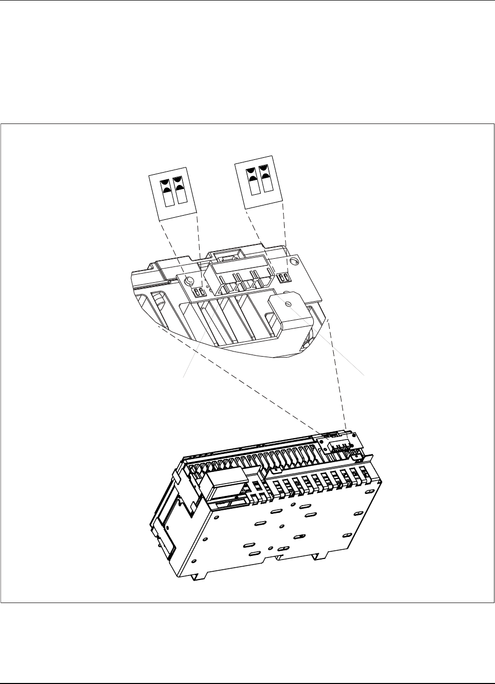
RBS 884 Pico (1900 MHz) Radio Head Installation
7.2 Radio Head DIP Switches (E1 Only)
Locating Radio Head DIP Switches (E1 Only)
1. Locate the Radio Head DIP switches. Refer to Figure 4-7 on page 4-24
Primary PCM
Interface
Connector
Secondary
PCM Interface
Connector
Rear View of Radio Head
12
RX GND
TX GND
TX GND
RX GND
12
ON ON
Figure 4-7. Radio Head Interface Ports and DIP Switches
4-24 2/1531-AE/LZB 119 3834 Uae Rev PA6 2001-04-04

RBS 884 Pico (1900 MHz) Radio Head Installation
Setting the TX and RX DIP Switches (E1 Only)
2. Set the TX and RX DIP switches to grounded (ON) or non grounded
(OFF) depending on the local transmission requirements.
Note: The DIP switches located beside the Primary PCM
Interface Connector are for uplink transmission
(primary). The DIP switches located beside the
Secondary PCM Interface Connector are for
downlink transmission (secondary).
8 Equipment Installation
8.1 Radio Head Installation
Preparation
1. Verify that power has been removed from the Radio Head.
2. Ensure that the CRI cabinet installation procedure is complete prior to
starting the Radio Head installation procedure. The CRI cabinet must
have one EMRPS unit installed for each Radio Head.
Note: If the number of EMRPS units in the CRI cabinet is
not known, consult the next level of maintenance
support or the site engineer.
Preparation for Mounting Optional Patch Antenna Assembly
3. Verify that the optional patch antenna assembly is on site.
Note: Do not install the optional patch antenna assembly
at this time.
4. Disconnect the monopole antenna cable from the external duplexer
using an open-ended wrench.
2/1531-AE/LZB 119 3834 Uae Rev PA6 2001-04-04 4-25
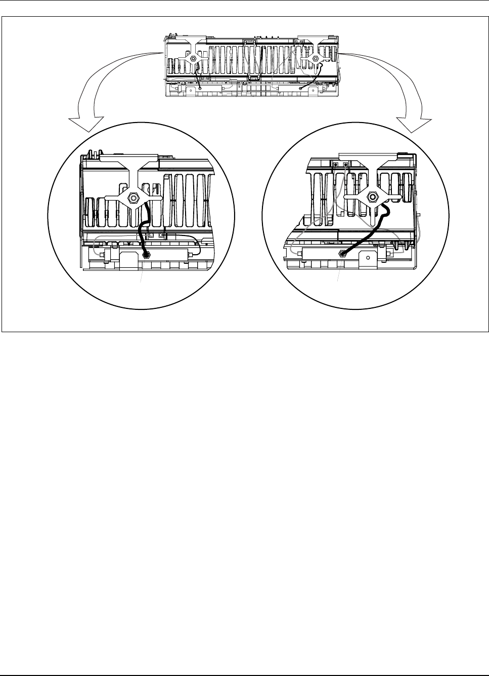
RBS 884 Pico (1900 MHz) Radio Head Installation
Monopole Antenna
Cable Monopole Antenna
Cable
Figure 4-8. Disconnecting the Monopole Antenna Cable
5. Carefully remove two screws from each monopole antenna bracket
assembly. See Figure 4-9 on page 4-27 for the location of the screws
and the monopole antenna bracket assembly. Save the bracket assembly
and the monopole antenna (NTM/KRE 101 1609) for possible future
use. The antenna bracket may be used to mount external antennas.
4-26 2/1531-AE/LZB 119 3834 Uae Rev PA6 2001-04-04
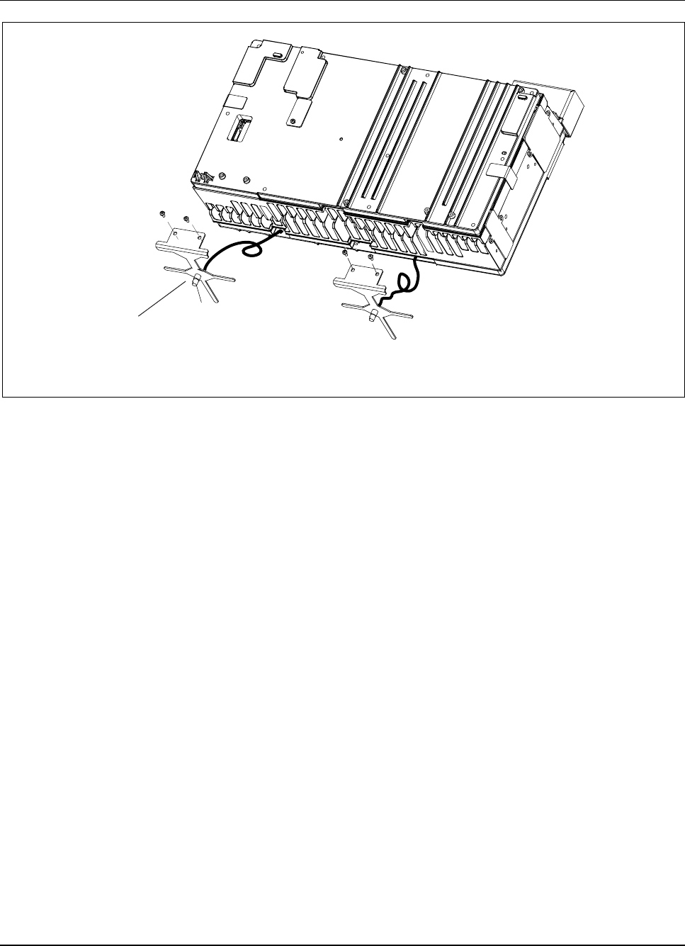
RBS 884 Pico (1900 MHz) Radio Head Installation
Antenna
Bracket
Assembly
TNC
Connector
Figure 4-9. Monopole Antenna Bracket Assembly
6. Mount the Radio Head wall bracket and Radio Head prior to installing
the optional patch antenna assembly.
Install Radio Head Mounting Bracket
7. Complete the prerequisites described in Section 6 on page 4-8.
8. Select a vertical surface to install the Radio Head.
9. Allow for the following minimum clearance requirements:
•23 cm (9 in) above top of bracket
•15 cm (6 in) below bottom of bracket
•30 cm (12 in) on each side of bracket
Note: The Radio Head must be installed on a vertical
surface.
10. Verify that a dedicated electrical outlet is installed 1 to 1.5 m (3 to 5 ft)
from the selected Radio Head location.
11. Using the mounting bracket as a template, mark the wall at the top-left,
top-right, and lower-right anchor-hole locations.
2/1531-AE/LZB 119 3834 Uae Rev PA6 2001-04-04 4-27
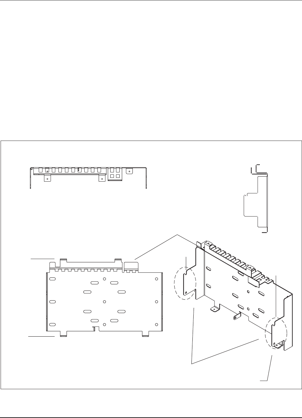
RBS 884 Pico (1900 MHz) Radio Head Installation
12. Drill holes appropriate for the length of the anchor to be used. Use a
minimum of four mounting points.
Note: The hardware must support a minimum of 22.7 kg
(50 lb). Use a minimum of four mounting points.
For example, use a minimum of four 3/8 in diameter
bolts to distribute the weight of the Radio Head
evenly between the bolts.
13. Use the appropriate mounting hardware (bolts, clamps or screws) for
securing the mounting bracket (for example dry wall, brick, masonry,
or a steel girder). See Figure 4-10 on page 4-28 for an illustration
of the mounting bracket.
Note: The mounting hardware is not included with the
mounting bracket.
Top View of Mounting Bracket
Side View
of Mounting Bracket
Top
Bottom
Front View of Mounting Bracket
Radio Head
Mount Points Bottom
Top
Notch
Notch
Figure 4-10. Radio Head Mounting Bracket
4-28 2/1531-AE/LZB 119 3834 Uae Rev PA6 2001-04-04
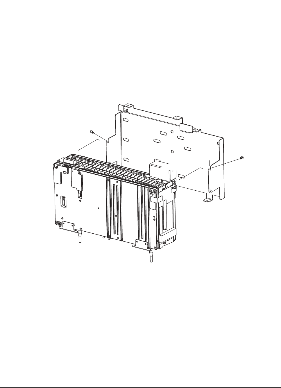
RBS 884 Pico (1900 MHz) Radio Head Installation
Install Radio Head on Mounting Bracket
14. Install, but do not tighten, one tamper-resistant screw in top hole on
each side of the Radio Head. Leave a sufficient gap between the screw
and the Radio Head to allow the screw to slip into the notch on the
mounting bracket. See Figure 6-19 on page 6-48 for the location of the
top holes on the Radio Head.
Note: Hardware Kit (NTM 201 1581) contains screws and
Torx driver tool for installing the Radio Head.
Radio Head
Mounting Bracket
Slot
Mount Point
Tamper-Resistant
Screw (Left Side)
Tamper-Resistant
Screw (Right Side)
Mount Point
Slot
Figure 4-11. Attaching Radio Head to Mounting Bracket
15. Place the Radio Head between the two mount points and slide the
tamper-resistant screws into the notches to support the Radio Head
on the mounting bracket.
16. Install a second tamper-resistant screw into the lower hole on each side
of the Radio Head. See Figure 4-12 on page 4-30 for the location of
the lower holes on the Radio Head.
2/1531-AE/LZB 119 3834 Uae Rev PA6 2001-04-04 4-29