HARRIS M803M OpenSky M-803 Mobile Radio Systems User Manual WIRELESS
Harris Corporation OpenSky M-803 Mobile Radio Systems WIRELESS
HARRIS >
Contents
- 1. Dash Mount Installation Guide
- 2. Trunk Mount Installation Guide
- 3. Operators Manual
Dash Mount Installation Guide
WINST-0004 Rev A WIRELESS SYSTEM BUSINESS UNIT
SUBJECT: M-803 Dash-Mount Installation Instructions DATE: August 16, 2001
Page 1 of 14
COPYRIGHT ©2001 Printed in U.S.A.
M/A-COM
1011 Pawtucket Boulevard
Lowell, MA 01853
1-877-OPENSKY
(1-877-673-6759)
1-877-OPENSKY
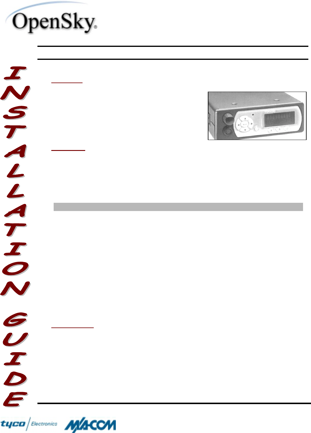
OVERVIEW
This document describes the procedure for
installing the M/A-COM OpenSky® Model M-803
Dash-Mount Mobile Radio in a vehicle, such as
an automobile, truck, or van. This is a general
guide only, and assumes that the installation will
be performed by a professional radio installer.
MATERIALS
The M-803 Dash-Mount Radio is designed to mount under or onto the dash inside
the passenger compartment of a vehicle. The installation kit (M/A-COM Part No.
MAMROS0017) needed to install the Radio is described below. The following table
describes the different accessories that are included in the kit:
Table I – Installation Kit Items
Item Qty Part Number Description
1 1 1000003774 Dash-Mount Bracket
2 1 1000005187-0001 Unity Gain Antenna, Quarter-wave
3 1 1000005809-0002 Fuse Kit, 15A
4 1 1000005824-0002 DC Power Cable (3m)
5 1 1000005828-0002 Speaker Cable Assembly
6 1 1000005928-0001 Microphone Head
7 1 1000005975-0002 Microphone Cable Assembly
8 1 AD00006 Pkg. of 4 Screws, #8-32 PAN HD, Black
9 1 M5240 CAN Terminator, 3-Pin
10 1 CTC-000261 Speaker
11 1 MAMROS00023 GPS Antenna Kit*
* GPS Antenna Kit is only included if the corresponding radio is equipped
with an optional GPS Unit.
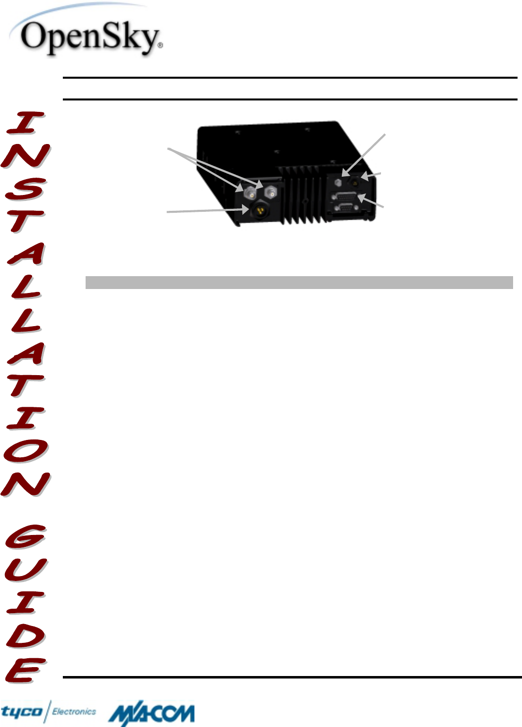
INSTRUCTIONS
Upon removing all items from the box and verifying that all have been included,
follow the following steps to install the M-803 Dash-Mount Radio. Refer to Figure 1
for location of connectors on the Radio.
WINST-0004 Rev A WIRELESS SYSTEM BUSINESS UNIT
SUBJECT: M-803 Dash-Mount Installation Instructions DATE: August 16, 2001
Page 2 of 14
COPYRIGHT ©2001 Printed in U.S.A.
M/A-COM
1011 Pawtucket Boulevard
Lowell, MA 01853
1-877-OPENSKY
(1-877-673-6759)
1-877-OPENSKY
Figure 1 Rear Panel
Actions Notes
1. Plan the mounting locations of all
components (Radio, Speaker,
Microphone, and Antenna), and
determine the routes for all wiring and
cables.
Determine the customer’s preferences, if any, for
location of components. Comply with these
preferences insofar as they are consistent with
safety, manufacturer specifications, and
generally accepted professional practices.
Make certain that drilling holes or inserting
screws will not damage or interfere with any
existing vehicle components or wiring. Follow all
manufacturer requirements and guidelines for the
location of components.
2. Mount the bracket in the interior of the
vehicle. Mount the Bracket (Item 1) under or on top of the
dash according to the available space in the
vehicle. Screws for mounting the Bracket to the
dash are not included, as all installations are
different. The Bracket must be firmly held to the
surface in order to prevent unreasonable
vibration from damaging the Radio or loosening
connections.
For mounting on the transmission hump, select
appropriate hardware such as a mounting wedge
(not included in the Radio Installation Kit).
3. Mount the Radio onto the Bracket. Install the Mobile Radio into the Bracket using
the 4 screws (Item 8) and tighten with a
screwdriver until the bracket is firm and flush to
the surface of the Radio.
Speaker
Connection
Antenna
Connections
Power
Connection
CAN Port
Connection
GPS Antenna
Connection

WINST-0004 Rev A WIRELESS SYSTEM BUSINESS UNIT
SUBJECT: M-803 Dash-Mount Installation Instructions DATE: August 16, 2001
Page 3 of 14
COPYRIGHT ©2001 Printed in U.S.A.
M/A-COM
1011 Pawtucket Boulevard
Lowell, MA 01853
1-877-OPENSKY
(1-877-673-6759)
1-877-OPENSKY
Actions Notes
4. Assemble the Microphone Cable
Assembly onto the Microphone Head. Connect the Microphone Cable Assembly (Item
7) to the Microphone Head (Item 6) by sliding the
2-pin connector of the cable into the cavity of the
Microphone Head. Make sure the tab on the 2-
pin connector is on the same side as the cable
release hole on the back of the Microphone
Head. You will hear a click if properly inserted.
5. Install the Microphone Assembly into
the Mobile Radio. Plug the 14-pin connector of the Microphone
Cable (Item 7) into the mating connector on the
face of the Mobile Radio by aligning the
connector appropriately and pushing. You will
again hear a click if properly inserted.
6. Mount the Microphone Clip in the
interior of the vehicle. The Microphone Clip is included in the package
with the Microphone Head (Item 6). Ensure that
the Microphone Clip is connected to the vehicle’s
chassis ground by either screwing the mounting
screws directly into the chassis or by providing a
jumper wire to a lug that is attached to the Clip.
The Radio has a monitor function that can be
used when the Microphone is cradled in the Clip.
7. If an optional CH-103 Control Head is
not being used with the M-803 Mobile
Radio, a CAN Terminator needs to be
installed.
Install the CAN Terminator (Item 9) onto the 3-
pin connector at the rear of the Radio by aligning
the connector appropriately and twisting the
outer housing clockwise until it stops.
8. Mount the Speaker in the interior of
the vehicle and connect it to the
Radio.
Install the Speaker (Item 10) in an area of the
front or rear dash that will allow for proper
listening range for voice operation. Use the
hardware and mounting bracket supplied with it.
Refer to the Speaker manufacturer’s instructions
included in the Speaker Assembly kit for
additional installation guidance.
Install the Speaker Cable Assembly (Item 5) onto
the 15-pin connector at the rear of the Radio
using a screwdriver. Do not over-tighten the
screws.
Connect the 2-pin connector on the Speaker
(Item 10) to the mating connector on the Speaker
Cable Assembly (Item 5). Route the excess

WINST-0004 Rev A WIRELESS SYSTEM BUSINESS UNIT
SUBJECT: M-803 Dash-Mount Installation Instructions DATE: August 16, 2001
Page 4 of 14
COPYRIGHT ©2001 Printed in U.S.A.
M/A-COM
1011 Pawtucket Boulevard
Lowell, MA 01853
1-877-OPENSKY
(1-877-673-6759)
1-877-OPENSKY
Actions Notes
cable out of the way of casual contact.
9. Mount the Antenna at a suitable
location on the vehicle, and route the
Antenna Cable inside the vehicle for
connection to the Radio.
The Antenna (Item 2) that is included in the kit
must be mounted by drilling a hole. The optimal
position of the antenna is in the direct center of
the roof of the vehicle. Refer to Antenna
Mounting Configurations for requirements
necessary to follow when selecting the proper
mounting area for the antenna. Also, refer to the
antenna manufacturer’s mounting and testing
instructions included in the Antenna Assembly kit
for installation guidance once the mounting area
is determined.
Route the cable from the Antenna (Item 2) to the
rear of the Radio out of the way of casual
contact. Install the Mini-UHF connector of the
cable to the mating connector at the rear of the
cable by tightening until finger-tight. It is
important that this connector is tight to prevent
RF leakage from occurring, but not too tight that
damage occurs.
Do not connect the antenna cable to the Radio
until satisfactory completion of testing into a
dummy load (refer to Testing Into a Dummy
Load).
10. If an optional GPS unit is included in
the Radio, the GPS Antenna needs to
be connected to the Radio.
Connect the SMA connector of the GPS Antenna
(Item 11) cable to the SMA connector on the rear
of the Radio and route the cable out of the way of
casual contact. The GPS Antenna is to be
mounted on the roof of the vehicle with one of
the 3 mounting configurations: Show-Mount, No
Show-Mount, and Magnetic Mount. The Antenna
must be kept at least 1 foot from any other
antenna mounted on the vehicle and have at
least 6 inches of ground plane beneath it.
11. Prepare for connecting the power to
the Radio through the vehicle’s
firewall.
Plan the cable route carefully, using an existing
access hole through the engine firewall if
possible. Alternatively, drill a new hole
approximately 3/8" in diameter and install a
rubber grommet to protect the cable.
NOTE Improper
installation of the antenna may
lead not only to poor radio
performance, but to harmful
exposure as well. See Antenna
Mounting Configurations below.

WINST-0004 Rev A WIRELESS SYSTEM BUSINESS UNIT
SUBJECT: M-803 Dash-Mount Installation Instructions DATE: August 16, 2001
Page 5 of 14
COPYRIGHT ©2001 Printed in U.S.A.
M/A-COM
1011 Pawtucket Boulevard
Lowell, MA 01853
1-877-OPENSKY
(1-877-673-6759)
1-877-OPENSKY
Actions Notes
12. The Fuse for Radio power must be
installed in-line with raw battery
voltage.
Strip one end of the wire included in the Fuse Kit
(Item 3) and crimp the terminal lug onto it. Cut
the wire to a length of about 6 inches and strip
the end to a length indicated by the gauge on the
fuse holder. Insert this end into the fuse holder
until the wire cannot go any further and crimp the
connection to the fuse holder. Use heat-shrink
tubing to protect the connection from foreign
materials. Connect the remaining wire in a similar
fashion to the other end of the fuse holder.
Connect the terminal to the vehicle’s battery in
the engine compartment. Route the wire through
a wire loom and pass it through the firewall using
a grommet to ensure the wire is not damaged.
13. Prepare the ground and sense
connections prior to applying power to
the Radio.
Connect the DC Power Cable (Item 4) to the 3-
pin connector at the rear of the Radio. Locate a
chassis ground close to the Radio and strip back
any jacket insulation around the wires to allow for
the shortest distance of the black wire. Cut the
negative (black) wire as short as possible, strip it,
and crimp the terminal to it. Screw it into the
chassis ground, ensuring a reliable metal-to-
metal contact.
Connect the sense (white) wire of the DC Power
Cable (Item 4) to an appropriate terminal to
connect to a fused ignition sense in the fuse box
and route the excess wire out of the way of
casual contact.
14. Apply the DC power connection to the
Radio.
NOTE Unlike many mobile
radios, the OpenSky® Mobile Radio
powers up immediately upon
application of DC power.
Using a pigtail, butt-splice, or solder-sleeve,
connect the positive (red) wire of the DC Power
Cable (Item 4) to the fuse wire (Item 3) and route
the excess wire out of the way of casual contact.
15. Test the output of the installed Radio
into a dummy load to verify that it
meets specifications.
Refer to Testing Into a Dummy Load under
Testing below for the procedure.

WINST-0004 Rev A WIRELESS SYSTEM BUSINESS UNIT
SUBJECT: M-803 Dash-Mount Installation Instructions DATE: August 16, 2001
Page 6 of 14
COPYRIGHT ©2001 Printed in U.S.A.
M/A-COM
1011 Pawtucket Boulevard
Lowell, MA 01853
1-877-OPENSKY
(1-877-673-6759)
1-877-OPENSKY
Actions Notes
16. Connect the Antenna and test the
Radio’s forward and reflected power
to verify transmission performance.
Refer to Testing With the Antenna under Testing
below for the procedure.
17. Complete the installation by
organizing, securing, and checking all
cables and components.
Take whatever steps are practical to make the
installation neat and functional for the Radio’s
user. Organize and secure all cables; make sure
all connections are tight.
TESTING
This section sets forth procedures to verify the performance of the installed radio.
Testing uses a wattmeter (or, alternatively, a VSWR meter) to measure RF power.
There are three procedures in this section: Changing Operating Modes, Testing Into
a Dummy Load, and Testing With the Antenna. Note that while the radio’s normal
operating mode for voice or data communications is OpenSky® Trunking Protocol
(OTP), the radio must be operating in OpenSky® Conventional FM (OCF) mode for
testing. Follow the procedure under Changing Operating Modes to switch between
the OCF and OTP modes.
Note also that the accuracy of test results depends on a radio power source in the
range of 13.8–16 volts DC at greater than 8 amps. Make sure the vehicle’s battery is
fully charged by running the engine for a few minutes before the test, and keep the
engine running during the test procedures.
Test Equipment Comments
Wattmeter Bird Electronic Corporation Model 43 or
equivalent, with N-Series female connectors on
both the input and output sides
As an alternative to using a wattmeter, a
Voltage Standing Wave Ratio (VSWR) meter,
Bird Electronic Corporation Model 4391A or
equivalent, can be used to carry out the
required RF (radio frequency) power testing.
Slug For use with the wattmeter; rated power of 25
watts and frequency range appropriate to the
800 MHz output of the OpenSky® radio (Bird
Electronics Element APM-25E (25 watts, 400–
1000 MHz) or equivalent)

WINST-0004 Rev A WIRELESS SYSTEM BUSINESS UNIT
SUBJECT: M-803 Dash-Mount Installation Instructions DATE: August 16, 2001
Page 7 of 14
COPYRIGHT ©2001 Printed in U.S.A.
M/A-COM
1011 Pawtucket Boulevard
Lowell, MA 01853
1-877-OPENSKY
(1-877-673-6759)
1-877-OPENSKY
Coaxial Cable Jumper Cable with Mini-UHF male connector on one
end and N-Series male connector on the other
end, approximately three feet in length
(Pasternack Enterprises PE3282-36 or
equivalent)
N-Series to Mini-UHF Adapter N-Series male to Mini-UHF female (Pasternack
Enterprises PE9064 or equivalent)
Dummy Load RF terminator rated at 50 ohms resistance and
greater than 50 watts power, with N-Series
male connector (Pasternack Enterprises
PE6106 or equivalent)
Antenna See the following section.
Antenna Mounting Configurations
This radio has been tested and complies with the FCC RF exposure limits for
Uncontrolled Exposure and Occupational exposure. The difference is in the minimum
safe distance that people must be away from the antenna when transmitting RF
energy. To assure optimal radio performance and that human exposure to RF
electromagnetic energy is within the guidelines, transmit only when people are at least
the minimum distance away from a properly installed antenna. Table II lists the
minimal distances.
Table II - M-803 Mobile Radio Minimum Safe Distances
Rated Power of
OpenSky M-803
Mobile Radio
Antenna
Gain M/A-COM
Recommended
Antenna
Minimum
Distance from
Transmitting
Antenna for
Uncontrolled
Exposure
Minimum
Distance from
Transmitting
Antenna for
Occupational
Exposure
45 dBm max,
43 dBm nominal 0 dB Maxrad #Z322
Unity Gain,
Quarter-Wave,
Rooftop
68.5 cm (27
inches) 30.6 cm (12
inches)
45 dBm max,
43 dBm nominal 3 dB Antenna
Specialists
#ASPA1860M
3dB, Rooftop;
#ASP915 3dB,
Elevated-Feed,
Various Mounts
97.6 cm (38.4
inches) 43.2 cm (17
inches)

WINST-0004 Rev A WIRELESS SYSTEM BUSINESS UNIT
SUBJECT: M-803 Dash-Mount Installation Instructions DATE: August 16, 2001
Page 8 of 14
COPYRIGHT ©2001 Printed in U.S.A.
M/A-COM
1011 Pawtucket Boulevard
Lowell, MA 01853
1-877-OPENSKY
(1-877-673-6759)
1-877-OPENSKY
There are various vehicles that have various physical dimensions that are not
standard, so selection of an antenna location is not trivial. Using Table II as a guide for
determining the best possible mounting configuration in order to reduce human
exposure, there are three possible locations on a vehicle where the antenna can be
mounted, described as follows:
Rooftop Center The center of the roof of a vehicle is the optimal location for the
rooftop antenna. The mounting area under the antenna must be a flat, metallized
ground plane, and it must be located directly in the center of the roof. If other
obstructions, such as a light bar or another antenna, prevent the antenna from being
mounted in the direct center of the roof, the antenna should be mounted, preferably, a
minimum of one foot away from the obstruction, but in the middle of the roof with
respect to the left and right sides of the vehicle.
Trunk-Lid Center Certain vehicles do not allow for the antenna to be placed in the
center of the roof. In this case, the next optimal location for the antenna is in the center
of the trunk lid. Again, the mounting area under the antenna must be a flat, metallized
ground plane, and it must be located directly in the center of the trunk lid. There are no
other preferable solutions for mounting this antenna if other obstructions prevent the
antenna from being mounted in the direct center of the trunk lid.
Trunk-Lip Center Some antennas have a feature that allows them to be mounted on
the lip of the trunk lid. In this case, the antenna is mounted on the top lip and in the
direct center of the trunk lid. Again, there are no other preferable solutions for
mounting this antenna if other obstructions prevent the antenna from being mounted in
the direct top center of the trunk lid.
Changing Operating Modes (Preliminary)
Actions Notes
1. Press the UP ARROW button on the
navigation pad repeatedly until the
message “MODE” appears on the unit’s
display, then press the SELECT button.
The buttons controlling the radio’s operating
parameters are on the left side of the front of the
radio.
2. Press the RIGHT ARROW button on
the navigation pad repeatedly until the
message “OCF” appears, then hit the
SELECT button.
Select the desired operating mode, where the mode
is one of the following:
•“OCF”—To perform testing
•“OTP”—To operate the radio for normal voice or
data communications

WINST-0004 Rev A WIRELESS SYSTEM BUSINESS UNIT
SUBJECT: M-803 Dash-Mount Installation Instructions DATE: August 16, 2001
Page 9 of 14
COPYRIGHT ©2001 Printed in U.S.A.
M/A-COM
1011 Pawtucket Boulevard
Lowell, MA 01853
1-877-OPENSKY
(1-877-673-6759)
1-877-OPENSKY
Actions Notes
3. Press the RIGHT ARROW button once
to confirm the selection, then press the
SELECT button to select the mode.
The radio is now in OCF mode.
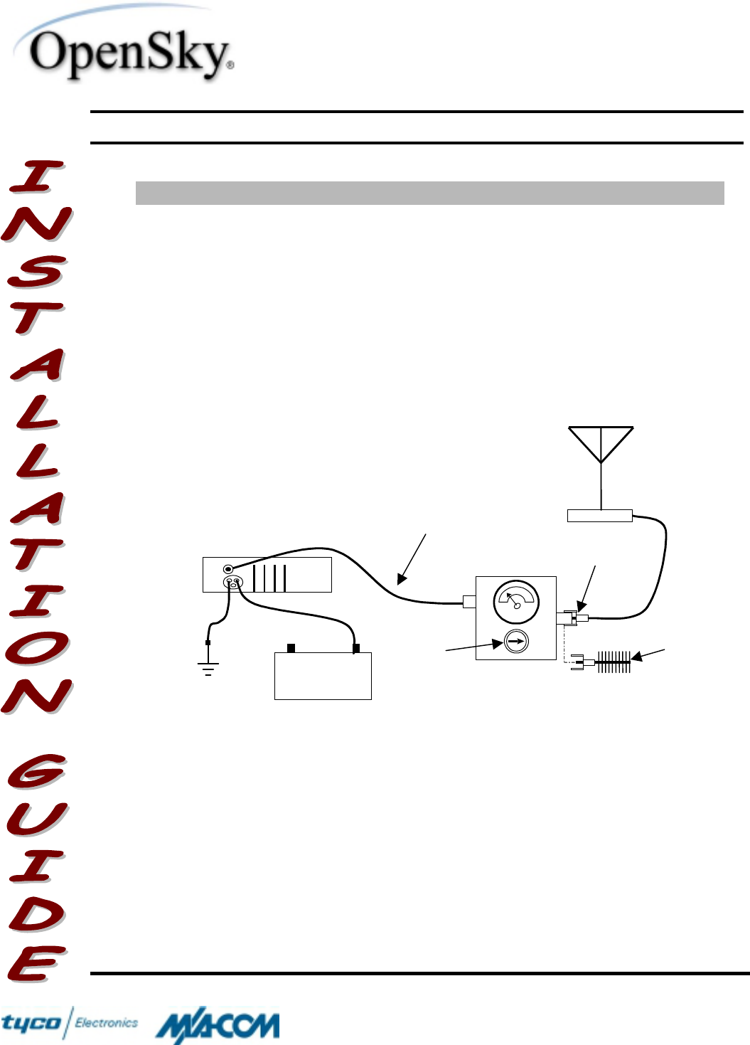
Testing Into a Dummy Load
Actions Notes
1. Connect the wattmeter to the radio
for testing according to Figure 2,
using the dummy load in place of
the antenna.
The dummy load connects to the output
side of the wattmeter, in place of the
antenna cable (see Figure 2).
2. Apply power to the radio and
switch to OCF mode, if necessary. The radio must be operating in OCF
mode in order to continue with the
testing procedure. If the radio does not
display “OCF” during startup indicating
that it is initializing in OCF mode, use the
procedure under Changing Operating
Modes above.
3. Position the slug to measure
forward RF power output. Rotate the slug, if necessary. The arrow
on the face of the slug must point from
the radio toward the dummy load to
measure forward power.
4. Measure the radio’s RF power
output. Key the microphone and note the
wattmeter reading. De-key the
microphone.
5. Compare the wattmeter reading
with the target RF power output
range specified in the Notes
column, opposite.
15–21 watts
TARGET VALUE RANGE
WINST-0004 Rev A WIRELESS SYSTEM BUSINESS UNIT
SUBJECT: M-803 Dash-Mount Installation Instructions DATE: August 16, 2001
Page 10 of 14
COPYRIGHT ©2001 Printed in U.S.A.
M/A-COM
1011 Pawtucket Boulevard
Lowell, MA 01853
1-877-OPENSKY
(1-877-673-6759)
1-877-OPENSKY
Actions Notes
6. Record the wattmeter reading for
RF power output into a dummy
load, or take remedial action and
measure the output again.
If the wattmeter reading is within the
target range, record the value in the
appropriate space on the data collection
sheet at the end of this guide.
If the wattmeter reading is outside the
target range, recheck the power source
and all connections and measure the RF
output power again. If this fails to
produce a reading within the target
range, replace the radio and repeat this
procedure.
Figure 2—Wattmeter Connection
OpenSky™
Mobile Radio
PWR
Wattmeter
N-Series to Mini-
UHF Adaptor
Mini-UHF to N-Series
Coaxial Jumper
Slug
(25 W, 400–
1000 MHz)
Dummy
Load
Vehicle
Battery
–+
Ground
Antenna

WINST-0004 Rev A WIRELESS SYSTEM BUSINESS UNIT
SUBJECT: M-803 Dash-Mount Installation Instructions DATE: August 16, 2001
Page 11 of 14
COPYRIGHT ©2001 Printed in U.S.A.
M/A-COM
1011 Pawtucket Boulevard
Lowell, MA 01853
1-877-OPENSKY
(1-877-673-6759)
1-877-OPENSKY
Testing With the Antenna
Actions Notes
1. Connect the wattmeter to the radio
and antenna for testing according
to Figure 2.
Remove the dummy load, if necessary,
and connect the antenna lead to the
output side of the wattmeter (see
Figure 2).
2. Apply power to the radio and
switch to OCF mode, if necessary. The radio must be operating in OCF
mode in order to continue with the
testing procedure. If the radio does not
display “OCF” during startup indicating
that it is initializing in OCF mode, use the
procedure under Changing Operating
Modes above.
3. Position the slug to measure
forward RF power output. Rotate the slug, if necessary. The arrow
on the face of the slug must point from
the radio toward the antenna to measure
forward power.
4. Measure the radio’s forward RF
power output. Key the microphone and note the
wattmeter reading. De-key the
microphone.
5. Compare the wattmeter reading
with the target RF power output
range specified in the Notes
column, opposite.
15–21 watts
TARGET VALUE RANGE

WINST-0004 Rev A WIRELESS SYSTEM BUSINESS UNIT
SUBJECT: M-803 Dash-Mount Installation Instructions DATE: August 16, 2001
Page 12 of 14
COPYRIGHT ©2001 Printed in U.S.A.
M/A-COM
1011 Pawtucket Boulevard
Lowell, MA 01853
1-877-OPENSKY
(1-877-673-6759)
1-877-OPENSKY
Actions Notes
6. Record the wattmeter reading for
forward power, or take remedial
action and measure the output
again.
If the wattmeter reading is within the
target range, record the value in the
appropriate space on the data collection
sheet below.
If the wattmeter reading is outside the
target range, verify that the radio’s
operating voltage is within the specified
range, recheck all connections, and
measure the forward power again. If this
fails to produce a reading within the
target range, check all cabling and
connections, and repeat the testing
procedure to this point. In the event the
wattmeter reading still falls outside the
target range, replace the antenna, make
sure all connections are seated firmly,
and repeat the testing procedure.
7. Position the slug to measure
reverse, or reflected, RF power. Rotate the slug. The arrow on the face of
the slug must point from the antenna
toward the radio to measure reverse, or
reflected, power.
8. Measure the reverse, or reflected,
RF power. Key the microphone and note the
wattmeter reading. De-key the
microphone.
9. Compare the wattmeter reading
with the target RF power output
range specified in the Notes
column, opposite.
2 watts or less
TARGET VALUE RANGE
10. Record the wattmeter reading for
reverse power, or take remedial
action and measure the output
again.
If the wattmeter reading is within the
target range, record the value in the
appropriate space on the data collection
sheet at the end of this guide.
If the wattmeter reading is outside the
target range, make sure the antenna
installed is consistent with the radio’s
specified frequency range. Recheck all
antenna connections, and measure the
reverse power again. If this fails to

WINST-0004 Rev A WIRELESS SYSTEM BUSINESS UNIT
SUBJECT: M-803 Dash-Mount Installation Instructions DATE: August 16, 2001
Page 13 of 14
COPYRIGHT ©2001 Printed in U.S.A.
M/A-COM
1011 Pawtucket Boulevard
Lowell, MA 01853
1-877-OPENSKY
(1-877-673-6759)
1-877-OPENSKY
Actions Notes
produce a reading within the target
range, replace the antenna and repeat
the entire testing procedure.
Any value exceeding the maximum
allowable reflected power value will
result in a diminished radio output
signal.*
11. Return the radio to OTP mode for
normal communications. Use the procedure under Changing
Operating Modes above. The radio is
now ready for normal communications.
* The standard measure for comparing forward and reflected power is the Voltage Standing Wave Ratio (VSWR). Use the
values recorded for the installed radio’s forward and reflected power to compute the VSWR, if desired, using the following
formula:
FR PP
V
SWR
+= 1, where
RP
= reverse power and
FP
= forward power. This value is expressed as a ratio to
the ideal value of 1, for instance, 1.2:1.
Copyright © 2001 M/A-COM. All rights reserved. No part of this publication may be reproduced, transmitted,
transcribed, stored in a retrieval system, or translated into any language, in any form or by any means, electronic,
mechanical, photocopying, recording, or otherwise, without prior written permission from M/A-COM. The
information furnished herein is believed to be accurate and reliable. However, no responsibility is assumed by
M/A-COM for its use, or for any infringements of patents or other rights of third parties resulting from its use. All
trademarks are the property of their respective owners

WINST-0004 Rev A WIRELESS SYSTEM BUSINESS UNIT
SUBJECT: M-803 Dash-Mount Installation Instructions DATE: August 16, 2001
Page 14 of 14
1-877-OPENSKY
Enter the information requested on this data collection sheet. Clip this form and file it as a permanent record of the tested
performance of the installed radio.
Clip
!
Here
Forward Power With
Antenna
watts
Reflected Power
With Antenna
watts
Power Into a Dummy
Load
watts
Com
p
an
y
Per
f
ormin
g
Installation Technician Per
f
ormin
g
TestDate of Test
(mm/dd/yyyy)
Mobile Radio
Serial Number
Antenna Make and Model
Mobile Radio
Model and Rev
Rev