HARRIS M803M OpenSky M-803 Mobile Radio Systems User Manual Operators Manual
Harris Corporation OpenSky M-803 Mobile Radio Systems Operators Manual
HARRIS >
Contents
- 1. Dash Mount Installation Guide
- 2. Trunk Mount Installation Guide
- 3. Operators Manual
Operators Manual
M-803 Gemini Series
Mobile Radio
OTP 5.07
OCF 3.13

Revision History
Date Updated by Description of change
08/14/01 Dennis Giddings New
Notice of Copyright
This manual and the hardware and software it describes are copyright ©
2001 M/A-COM, Inc. All rights reserved under the copyright laws of the
United States and Canada and other laws. Without limiting the rights under
copyright, no part of this document may be reproduced, stored in or
introduced into a retrieval system, or transmitted in any form or by any
means (electronic, mechanical, photocopying, recording, or otherwise), or
for any purpose, without the express written permission of M/A-COM, Inc.
The contents of this manual are not intended to and do not constitute a
warranty of any sort. M/A-COM, Inc and Tyco Electronics specifically
disclaim any implied warranties of merchantability or fitness for any
particular purpose resulting from this manual.
Information in this document is subject to change without notice. M/A-
COM, Inc. reserves the right to revise and make changes to this manual (and
to the Kensington product and software) from time to time without
obligation to notify any person of, or to provide any person with, such
revisions or changes.
M/A-COM, Inc. and/or Tyco Electronics may have patents, patent
applications, trademarks, copyrights, or other intellectual property rights
covering subject matter in this document. Except as expressly provided in
any written license agreement from M/A-COM, the furnishing of this
document does not give you any license to these patents, trademarks,
copyrights, or other intellectual property.
©2001 M/A-COM, Incorporated. All rights reserved.
Document # TBSL. Part No. 000-0000
Printed in the United States of America

Software Version OTP 5.07 M-803 Operator Manual iii
iiiiii
iii
Preface
Notices to the User and Safety
Training Information
IMPORTANT INFORMATION ON SAFE AND
OPTIMAL OPERATION. READ THIS BEFORE
USING YOUR M-803 MOBILE RADIO
WARNING
Your M-803 radio generates RF electromagnetic
energy during transmit mode. This radio is designed
for and classified as “Occupational Use Only”
meaning it must be used only during the course of
employment by individuals aware of the hazards and
the ways to minimize such hazards. This radio is
NOT intended for use by the “General Population”
in an uncontrolled environment.
This radio has been tested and complies with the FCC
RF exposure limits for “Occupational Use Only.” In
addition, your M-803 radio complies with the
following Standards and Guidelines with regard to RF
energy and electromagnetic energy levels and
evaluation of such levels for exposure to humans:
• FCC OET Bulletin 65 Edition 97-01 Supplement
C, Evaluating Compliance with FCC Guidelines
for Human Exposure to Radio Frequency
Electromagnetic Fields.
• American National Standards Institute (C95.1 –
1992), IEEE Standard for Safety Levels with
Respect to Human Exposure to Radio Frequency
Electromagnetic Fields, 3kHz to 300 GHz.
Use of this radio as described below will result in user
exposure substantially below the FCC recommended
limits for human exposure to Radio Frequency
Electromagnetic energy.

iv
iviv
iv M-803 Operator Manual Software Version OTP 5.07
Before operating this radio, be sure you:
• Do not operate this radio if any of the RF
connectors are not secure or if open connections
are not properly terminated.
• Do not operate this radio near electrical blasting
caps or in an explosive atmosphere.
This radio has been tested and complies with the FCC
RF exposure limits for Uncontrolled Exposure and
Occupational exposure. The difference is in the
minimum safe distance that people must be away from
the antenna when transmitting RF energy. To assure
optimal radio performance and that human exposure to
RF electromagnetic energy is within the guidelines,
transmit only when people are at least the minimum
distance away from a properly installed antenna. The
following lists these minimal allowable distances:
M-803 Radio
Rated Power Antenna
Gain Minimum
Distance for
Uncontrolled
Exposure
Minimum
Distance for
Occupational
Exposure
45 dBm max,
43 dBm nominal 0 dB 68.5 cm (27
inches) 30.6 cm (12
inches)
45 dBm max,
43 dBm nominal 3 dB 97.6 cm (38.4
inches) 43.2 cm (17
inches)
The radio must be serviced and installed only by a
qualified technician. Be sure that the radio is properly
grounded according to the installation instructions.
Note on jump-starting: If you need to jump start an M-
803 equipped vehicle, the positive radio lead from the
radio must be disconnected from the vehicle battery.
Disconnecting the lead will prevent damage to the radio.
This equipment generates or uses radio frequency
energy. Changes or modifications to this equipment
may cause harmful interference unless the
modifications are expressly approved in the instruction
manual. The user could lose the authority to operate
this equipment if an unauthorized change or
modification is made.

Software Version OTP 5.07 M-803 Operator Manual v
vv
v
This equipment has been tested and found to comply
with the limits for a Class B digital device pursuant to
Part 15 of the FCC Rules. These limits are designed to
provide reasonable protection against harmful
interference in a residential installation.
Government law prohibits the operation of unlicensed
transmitters within the territories under government
control. Illegal operation is punishable by fine or
imprisonment or both. Refer service to qualified
technicians only. Do not operate your transceiver in
explosive atmospheres (gases, dust, fumes, etc.).
Occupational Safety Guidelines and
Safety Training Information
CAUTION
To ensure that your exposure to RF electromagnetic
energy is within the FCC allowable limits for
occupational use, always adhere to the following
guidelines.
Your M-803 Mobile Radio transmits using a remote
antenna. When it is ON, it receives and also sends out
radio frequency (RF) signals.
In 1996, the Federal Communications commission
(FCC) adopted RF exposure guidelines with safety
limits for portable devices, based on the recommended
limits of the National Council on Radiation Protection
and Measurements (NCRP) and the American National
Safety Institute (ANSI).
The design of the M-803 Mobile Radio complies with
the FCC guidelines for Occupational / Controlled
exposure to RF electromagnetic fields, as measured by
the Maximum Permissible Exposure (MPE). To assure
optimal performance and make sure human exposure to
RF electromagnetic energy is within the FCC
guidelines, always adhere to the following:
1. The push-to-talk button should only be depressed
when intending to send a voice message.
2. The radio should only be used for necessary work
related communications.
vi
vivi
vi M-803 Operator Manual Software Version OTP 5.07
3. The radio should only be used by authorized and
trained personnel and should not be operated by
children.
4. Do not operate your radio in explosive
atmospheres (gases, dust, fumes, etc.) or near
explosive blasting caps.
5. Do not attempt any unauthorized modification to
the radio. Changes or modifications to the radio
may cause harmful interference. Any servicing of
the radio should only be performed by qualified
personnel.
6. Always use M/A-COM authorized accessories
(antennas, control heads, speakers/mics, etc.). Use
of unauthorized accessories can cause the FCC RF
exposure compliance requirements to be exceeded.
The information listed above provides the user with the
information needed to make him or her aware of a RF
exposure, and what to do to assure that this radio
operates within the FCC exposure limits of this radio.

Software Version OTP 5.07 M-803 Operator Manual vii
viivii
vii
Table Of Contents
Welcome to the OpenSky Network 1
OpenSky Overview 2
Internet Protocol (IP) Network 2
TCP / IP Backbone 2
Addressable Headers 3
System-Wide Voice Encryptability 3
Integrated Voice and Data 3
Digitized Voice, Text and Graphics 4
Multi-Agency Coverage 5
Promotes Interagency Cooperation 5
Connectivity with Legacy Equipment 6
Improved Coverage and Signal Strength 6
Better Peak-Time Performance 7
Software-Configured Device 8
Multi-Mode Functionality 8
Software Upgradeable 9
Network Organization 11
Your Voice Feature Personality 12
User Groups 13
Profiles 14
Talk Groups 15
Listen Groups 15
Talkback Scanning 16
Radio Personality 16
Terminology 18
Getting Started 19
Before Your First Shift 20
Radio Controls 20
Front Panel Components 21
Peripheral Interface 23
RS-232 Port 23
I/O Connector 23
CAN 2.0 Bus 23
viii
viiiviii
viii M-803 Operator Manual Software Version OTP 5.07
Hardware Connections 23
Display Screen Overview 25
Dwell Displays 27
Dwell Display User-Selectable 27
Sample Dwell Displays 28
Dwell Display–Profile 28
Dwell Display-Caller 29
Dwell Display–Received Talkgroup 29
Dwell Display–Channel 30
Dwell Display–No Access 30
Display Screen Functions 33
Menu and Selector Keypad 34
User-Selectable Menu Operations 34
Keypad Navigation 34
Select Dwell Display 35
Select Operational Mode 36
Universal Connectivity 37
Duration of Mode Change 38
Select Profile 39
Check or Change Active Profile Status 40
Select Talkgroup 41
Check or Change Active Talkgroup 41
Prioritizing a Talkgroup 43
Duration of Priority Assignments 44
Lock Out Talkgroup 44
Groups You Can Lock Out 45
Caution Regarding Profile Changes 48
Select Scan Mode 48
Check or Change Active Scan Mode 49
Duration of Scanning Mode Selections 50
Select Channel 51
Enable/Disable Side Tones 52
Select Brightness Setting 53
Basic Radio Operations 55
Power Up 56
Log-On 57
Self-Test 58
Software Version OTP 5.07 M-803 Operator Manual ix
ixix
ix
Power Down 59
Set Volume 60
Voice Calls 61
Talkback Calls 63
Emergency Communications 64
Advanced Radio Operations 65
Fine-Tuning Your Personality 66
Dynamic Regrouping 66
Talkaround Mode 67
Troubleshooting 68
CH-103 Control Head 71
Features and Components 72
Equipment Configurations 73
Dash-Mount Mobile Configuration 73
Dash-Mount Mobile with CH-103 74
Trunk-Mount Mobile Configuration 76
VTac Vehicular Tactical Network 77
Full or Shared Radio Controls 78
Single Control Head 79
Multiple Control Heads 79
Independent Functions 79
Shared and Arbitrated Functions 80
VTac Vehicular Tactical Network 81
Vehicular Tactical Network 82
Backward and Forward Compatibility 82
Operational Modes 83
“A Base Station in a Trunk” 83
Hardware Components 84
VTac Mobile Unit 84
VTac Base Unit 85
RF Combiner 85
Extended Coverage 85
User Interaction 85
Scene of Incident 86
User Interaction 86
Public Safety Hardened 86
GPS Option 87

Software Version OTP 5.07 M-803 Operator Manual
1
CHAPTER 1
Welcome to the OpenSky Network
OpenSky Overview 2
Internet Protocol (IP) Network 2
TCP / IP Backbone 2
Addressable Headers 3
System-Wide Voice Encryptability 3
Integrated Voice and Data 3
Digitized Voice, Text and Graphics 4
Multi-Agency Coverage 5
Promotes Interagency Cooperation 5
Connectivity with Legacy Equipment 6
Improved Coverage and Signal Strength 6
Better Peak-Time Performance 7
Software-Configured Device 8
Multi-Mode Functionality 8
Software Upgradeable 9
CHAPTER 1—Welcome to the OpenSky Network
2
22
2
M-803 Operator Manual Software Version OTP 5.07
OpenSky Overview
M/A-COM’s OpenSky is a suite of radio communi-
cations products implementing an integrated digital
voice and data system based on the Internet Protocol.
The OpenSky network is digital, but provides inter-
operability with analog radios, making it possible to
integrate existing (legacy) equipment alongside the
most sophisticated digital equipment available today.
If you’ve been issued an M-803 to replace a
conventional analog voice-only radio, you’ll
particularly appreciate the integrated voice and data
capabilities of the all-digital OpenSky mobile
equipment.
Even experienced digital subscribers recognize and
value the addressability precision and expanded
coverage strength of the end-to-end TCP/IP OpenSky
Intranet.
Internet Protocol (IP) Network
OpenSky’s Wireless Private Network is changing the
nature of real-time communications for large fleet
mobile businesses and public safety organizations
alike.
TCP / IP Backbone
Using Internet Protocol (IP) as a network backbone for
end-to-end user applications, OpenSky integrates
digital voice and packet data transmission over a single
network that provides significant performance
advantages over yesterday’s uneasy alliances of
independently-built radio networks trying
unsuccessfully to interact.
• Like tuning into a channel in a conventional FM
radio system, logging onto the OpenSky network
with your pre-configured user profile will place
you in contact with the members of a software-

Welcome to the OpenSky Network—CHAPTER 1
Software Version OTP 5.07 M-803 Operator Manual 3
33
3
defined talk group consisting of the set of users
you need to talk with most.
• Unlike your conventional FM radio, your M-803
mobile radio is a node on an Internet-Protocol (IP)
network with its own unique IP address.
Addressable Headers
Messages intended for you (whether voice or data) are
broken into packets with identifying headers, just like
World Wide Web internet communications, and
targeted to your specific IP address.
You can travel anywhere within your network, even a
hundred miles or more from the sender, and messages
intended for your IP address will find their way across
the network, handed off from base station to base
station, until they are re-configured and delivered to
your personal receiving set.
This doesn’t mean your communications are traveling
across the World Wide Web. Far from it. OpenSky is a
private wireless Intranet that adopts the best features of
IP protocol for increased communications efficiency
and capacity.
System-Wide Voice Encryptability
Furthermore, your communications are packeted as
they travel the network, so they can only be deciphered
by networked equipment. Your sensitive conversations
and data transfers can even be encrypted end-to-end for
enhanced system-wide security.
Integrated Voice and Data
Your M-803 Gemini Series Mobile Radio is a
hardware component of the OpenSky network, an
integrated voice and data communications system that
delivers end-to-end digital voice and data transmissions
over a single wireless network to your dash-mounted or
trunk-mounted device.
Like cell-phone calls,
messages are delivered
directly to your
equipment.
But, like radio calls, users
select which calls to
receive by “tuning in” or
“locking out” other user
groups.

CHAPTER 1—Welcome to the OpenSky Network
4
44
4
M-803 Operator Manual Software Version OTP 5.07
Digitized Voice, Text and Graphics
By converting analog voice waves to digital code
before transmitting them over the network, OpenSky
technology makes it possible for mobile radio users to
send and receive voice transmissions at the same time
they receive and view data (via the radio’s serial port)
on an optional equipment Mobile Data Terminal.
For graphics, interface a
Mobile Data Terminal
(MDT) through your
radio’s RS-232 peripheral
port.
With an M-803 in your vehicle, you’ll be able to scroll
through complex instructions, driving directions, or
emergency warnings on an optional mobile computer
or terminal device while at the same time carrying on
conversations with dispatchers or other mobile
operators in your coverage area.
OpenSky and the M-803 eliminate the need to run
separate systems for voice communication and data
transmission. And, with OpenSky, you won’t even
have to switch between radio modes to do both
simultaneously.
RS-232 Interface
For data transfers or graphics, your M-803 is
constructed with an industry-standard RS-232 interface
serial port for connecting an optional equipment
Mobile Data Terminal (MDT), laptop PC or third-party
display or key-entry device.
OpenSky works seamlessly with equipment from
popular manufacturers and off-the-shelf applications
through a standard UDP/IP protocol, providing you
with simple “plug and play” connectivity.
Suddenly and simply, the same M-803 you’ve been
using for voice conversation and tuning radio
frequencies becomes the device you use to view
photographs, maps or driving directions, generate
reports, access databases, in short to share any digital
file your job requires.

Welcome to the OpenSky Network—CHAPTER 1
Software Version OTP 5.07 M-803 Operator Manual 5
55
5
Multi-Agency Coverage
OpenSky is scalable and designed to accommodate a
virtually unlimited number of mobile and portable
devices from a single fleet, or even a complex network
made up of several cooperating agencies.
Examples of how OpenSky improves cooperation:
• Every truck in the FedEx fleet can share one large
national network.
• Every cruiser in a state-wide police agency can
communicate with any other cruiser, from one end
of the state to the other.
• Patrolmen with older analog equipment can
connect seamlessly with newer digital devices over
the same network.
• Emergency response agencies share the same
network for improved communications during a
massive crisis.
• With an M-803 at the heart of your trunk-mounted
VTac Vehicular Tactical Network, your vehicle
provides off-network user-to-user communications
at the scene of an emergency.
Promotes Interagency Cooperation
See full discussions of
Talk Group, User Group
and User Profile else-
where in this manual.
In fact, the system is best suited to multi-agency public
safety networks over areas as large as an entire state:
every cruiser, ambulance and fire truck and all their
dispatchers and support personnel sharing voice, data,
even graphics over the same network.
Talk to Anyone on the Network
Each user needs only one radio to connect seamlessly
to many independent agencies or cooperating dispatch
networks.
• There’s no need to monitor multiple frequencies on
several pieces of equipment to maintain contact.

CHAPTER 1—Welcome to the OpenSky Network
6
66
6
M-803 Operator Manual Software Version OTP 5.07
• User talk groups connect you at all times with
precisely the users you need to reach, no matter
who they work for, or where they’re located within
the network.
Connectivity with Legacy Equipment
The all-digital, end-to-end TCP/IP OpenSky Intranet
even provides support for legacy equipment and
protocols both digital and analog.
Along with supplying voice and data to your M-803
mobile radio, the network will also support existing (or
“legacy”) radio equipment you may still need to use
during a hardware rollover.
This also means you’ll be able to make radio contact
with cooperating agencies on the same network,
whether or not they have made the conversion to
OpenSky equipment, as long as they use their radios to
network with OpenSky.
Voice and Data to a Single Device
For graphics, you’ll need
to remain connected to
your Mobile Data
Terminal (MDT).
With OpenSky, you won’t need independent system
architecture to receive voice and data communications.
And, with a Mobile Data Terminal connected through
the peripheral interface, you’ll have unprecedented
ability to send and receive forms, NCIC profiles, maps,
floorplans, all the complicated graphical data you need
to make informed on-the-job decisions.
Improved Coverage and Signal Strength
Part of OpenSky’s scalability is its ability to accommo-
date as many base stations as your coverage area
requires for robust voice and data transmissions,
wherever your route may extend within the network.
Vehicular Tactical Network
VTac devices (trunk-mounted M-803 radios arrayed
with a duplexer and a vehicular repeater) and OpenSky
cell sites automatically extend coverage into otherwise
hard-to-reach areas.

Welcome to the OpenSky Network—CHAPTER 1
Software Version OTP 5.07 M-803 Operator Manual 7
77
7
With a VTac device in your vehicle, you’ll enjoy
extended signal reach into buildings or behind barriers,
as well as repeater capability for off-network unit-to-
unit communications.
Background Roaming and Switching
Automated switching takes place in the background
with OpenSky, so you’ll no longer be required to scan
for an open channel, or wait for an available channel,
when you move through your coverage area.
Signal strength sensitivity
is user-modifiable to
reflect local conditions.
Instead of depending on choices from a central
switching station, your radio itself constantly monitors
signal strength and makes its own decision to roam to
another base site for a more robust connection.
Chances are you’ll never know your unit has been
“handed off” to a new base station and automatically
assigned to the best available channel.
Better Peak-Time Performance
OpenSky’s digital trunking architecture provides
enormous advantages over conventional FM operation.
Conversation capacity is effectively doubled by the
system’s ability to carry two voice-to-voice conver-
sations over the same channel that was previously
dedicated to just one.
TDMA Technology
The M-803 uses TDMA technology to allow multiple
users to share a single RF channel. In addition, a single
25kHz RF channel can support simultaneous digital
voice and data communications.
By doubling the capacity of each channel, the OpenSky
TDMA network relieves the pressure of heavy use
without additional channels.
The M-803 supports multiple voice groups, multi-level
priorities, priority scanning, dynamic voice group
assignment, pre-emptive emergency calls and optional
encryption.

CHAPTER 1—Welcome to the OpenSky Network
8
88
8
M-803 Operator Manual Software Version OTP 5.07
Optional GPS Tracking
GPS tracking devices embedded in optionally-equipped
M-803 radios quickly and accurately locate users on a
visual display screen for dispatchers, virtually
eliminating the need for users to report their position.
With an overview of the locations of all vehicles,
dispatchers have the information they need to assign
the nearest vehicle to a developing emergency.
By eliminating the background chatter of constant
location reporting, OpenSky frees up system resources
for more critical communications, especially at peak
traffic times.
Software-Configured Device
Your M-803 is a “soft” radio. Its functions are deter-
mined by OpenSky software applications, in much the
same way computer hardware is configured for
different applications.
Unlike older analog radios you may have used, with
their hardware-based proprietary functions, your
M-803 converts voice waves into digital information
before it transmits to the network, providing noise-free
audio transmission and reception.
Make any radio in the
system “your radio” by
logging on with your
identity code.
What’s more, because each user in the network has a
unique identity code, you can activate your identity
from any radio connected to the network. Any radio
from your agency’s hardware stockpile can become
“your” radio and log on with your profile.
Multi-Mode Functionality
Finally, if you need to be multi-mode, your M-803
supports several (even several applications simulta-
neously) providing capability with the needs of
different user groups.
You can operate under the OpenSky digital protocol or
use the same device to access Conventional FM with
CTCSS analog FM or APCO Project 25 Phase 1
operations, depending on the user configuration of your
network or agency.
GPS tracking uses a
small fraction of
system resources,
but eliminates verbal
location reporting for
huge overall
capability gains.

Welcome to the OpenSky Network—CHAPTER 1
Software Version OTP 5.07 M-803 Operator Manual 9
99
9
Analog-to-Digital Rollover
The M-803 can work with existing analog infra-
structure to enable an essentially seamless transition to
fully digital communications
If your user group or another user group with whom
you communicate is making the transition from analog
to digital service over time, you’ll be able to use your
M-803 throughout the rollover by selecting the correct
mode.
What’s more, the M-803 is field re-programmable over
the radio channel to allow for future capabilities
without replacing the existing subscriber equipment.
• The principle operating mode currently in use is
the OpenSky Trunked Protocol (OTP).
• From the Mode Selection Menu, you can also
access OpenSky Conventional FM (OCF) with
Continuous Tone Coded Squelch System
(CTCSS).
• From the Mode Selection Menu, you can also
access OpenSky Conventional (OCF) mode using
APCO Project 25 Common Air Interface.
Software Upgradeable
As with computer hardware, your mobile radio
equipment is upgradeable each time the OpenSky
software enables a new feature or operational
enhancement.
Communications protocols, radio features, and
protocols can be changed easily and transparently to
the user, during a shift or during “sign-on” at the
beginning of a new shift.
Enhanced Digital Features
The all-digital network and OpenSky’s digital trunking
features also enable a rich array of network enhance-
ments unthinkable over historical FM broadcast
systems.
See full discussions of
Talk Group, User
Group and profiles in
Chapter 2 of this
manual.
CHAPTER 1—Welcome to the OpenSky Network
10
1010
10
M-803 Operator Manual Software Version OTP 5.07
Voice grouping (into talk groups, user groups, and
profiles) is probably the most obvious advantage to
individual users, but the interconnectivity of the
OpenSky network also enables a variety of essential
enhancements including:
• Priority scanning
• Multiple priority levels
• Pre-emptive emergency calls
• Selective calls directly to User ID
• Late-entry calls
• Autonomous roaming for wide area applications.
You’ll benefit from high-quality, noise-free voice
communications with enhanced speech clarity
compared to analog, especially in noisy environments.

CHAPTER 2—Network Organization
12
1212
12
M-803 Operator Manual Software Version OTP 5.07
Your Voice Feature Personality
When you activate your radio at the beginning of a
shift and sign on with your unique identity code, your
radio is assigned its IP address and “provisioned” with
a radio personality that identifies the other users on the
network with whom you are most likely to need to
communicate.
Some users you’ll only monitor, others you’ll want to
talk with during the course of your shift, just as with
older analog equipment you talked over one frequency
and monitored others to keep informed about the
activities of users in your agency, workgroup, task
force, fleet or geographic area.
Profiles are assigned by
your network admini-
strator to match your
communication needs.
You’ll have access only
to those users who fall
within your profile.
Your overall radio personality is organized into User
Groups (talk groups and listen groups), similar to a
channel in a conventional FM radio system. These user
groups are then organized into Profiles (collections of
up to 16 user groups), similar to banks of channels.
Finally, as many as 16 profiles make up your radio
Personality.
Only one profile is active at any time. Within that
profile, only one user group is your Talk Group; the
others are Listen Groups. So, while you have
tremendous capability to establish contact with a very
large number of users, you’ll need to select the profile
that puts you into voice contact with the talk group you
need at any time.
Network Organization—CHAPTER 2
Software Version OTP 5.07 M-803 Operator Manual 13
User Groups
A user group is a set of users who regularly need to
communicate (all the officers in a state police barracks,
for instance, or all the drivers who work a particular
shift).
• In conventional FM radio broadcast systems,
these users work together by tuning to the same
channel.
• In the IP-backbone OpenSky digital network,
subscribers in a user group are connected by a bit
of data in the header of every voice or data packet
addressed to the members of the group.
With OpenSky, members of the same user group can
stay in contact regardless of where they roam within
the network, whether the network incorporates a single
county, a state, even the entire nation.
Network capacity is the
only limitation on the
number of users that can
make up a group.
Dispatchers maintain contact with all members of the
group, and each user can stay in “push-to-talk” contact
with the dispatcher and all the users in their talk group,
even if those users are from different, inter-networked
agencies.
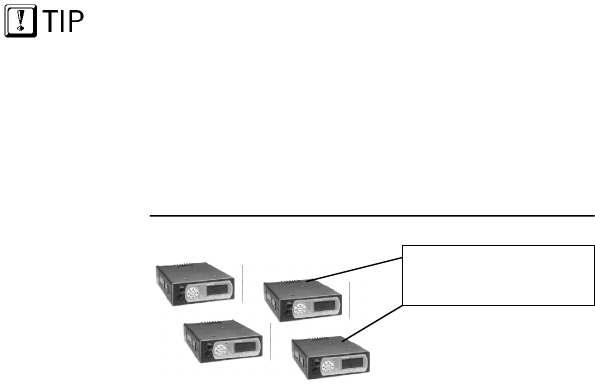
The Figure below illustrates a small user group of four
M-803 mobile radios.
Figure 1 User Group
Sample Configuration
Nothing about this user group so far defines it as a Talk
Group or a Listen Group. That determination is made
when user groups are gathered together by the network
administrator into the larger groups called profiles.
Each radio assigned
to an individual user

CHAPTER 2—Network Organization
14
1414
14
M-803 Operator Manual Software Version OTP 5.07
Profiles
A profile is a set of up to 16 user groups. All sorts of
configurations are possible within this simple
architecture. Police officers on the same shift might
make up a profile, for instance. Within this profile,
each police station on the network might be assigned a
user group. So the profile would connect all the
cruisers from 16 stations for an entire shift.
Officers from each station would most likely be in
“push-to-talk” contact with one another; all other
officers on the same shift would most likely monitor
the other groups for “listen-only” access to all other
calls within the profile. But this is only one possible
configuration.
Members of a talk group
are not necessarily
scanning the calls of the
same listen groups.
A user group might just as easily include officers from
several stations: a SWAT team, for example, or a
special emergency task force might require the
collaboration of special personnel or equipment from
different police stations, or even other agencies.
• In conventional FM radio broadcast systems,
users with this sort of relationship would create an
“ad hoc” profile by tuning to one channel for talk-
group privileges and scanning an entire bank of
channels to monitor the conversations of other
groups.
• In the IP-backbone OpenSky digital network,
members of the same talk group automatically
receive every voice message addressed to the
group, and monitor the voice messages of every
other user group in the profile.
Each user in the OpenSky network can be assigned as
many as 16 profiles by the network administrator. At
any time during a network session, users can select the
profile that suits their needs by using the front control
keypad to access the Profile Menu. If selected for
Dwell Display, the Current Profile selection will be
visible in the radio’s front panel display area.
Of the 16 available
profiles, Network
Administrators will often
reserve one for Dynamic
Regroup use.
Network Organization—CHAPTER 2
Software Version OTP 5.07 M-803 Operator Manual 15
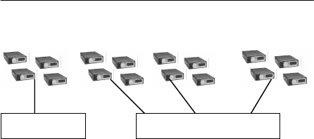
Figure 2 User Profile
Sample Configuration
User Group 1 User Group 2 User Group 3 User Group 16
. . .
Talk Groups
While your active profile can contain up to 16 user
groups, only the primary group in any profile is your
Talk Group. All the other user groups in your profile
are listen-only groups. You’ll hear the calls from these
groups but they will not hear your voice unless your
user group is part of their profile.
To initiate voice-to-voice contact with a particular user,
you’ll have to select the profile that makes that user
part of your talk group. This is only possible if your
network administrator has configured a talk group that
contains both you and the other user.
If each of you has a profile that includes the other in a
talk group, you can each select the profile that puts you
into “push-to-talk” contact with the other. (Or one of
you can reply to the other in Talkback Mode.)
Listen Groups
All the other user groups in each of your up to 16
profiles are “listen groups”. See the User Profile
Figure above for an illustration of how user groups are
related in a profile.
By adding different listen groups to your several
profiles, your network administrator can change the
configuration of the user groups you can monitor at any
time by making the appropriate choice from the Profile
menu.
Talk Group U
p
to 15 Listen Grou
p
s

CHAPTER 2—Network Organization
16
1616
16
M-803 Operator Manual Software Version OTP 5.07
You may only have one talk group, but that doesn’t
keep you from tuning in different profiles to monitor a
different “bank of channels.”
Talkback Scanning
While you cannot initiate contact with users in your
“listen groups,” you can reply to their incoming calls
using Talkback Scan mode.
With your radio in Talkback Mode, your display screen
will show the identity of your most recent incoming
caller. Press the Push-to-Talk button on your handset
and send your voice reply.
Radio Personality
Your radio personality is a collection of up to 16
profiles. The entire personality is organized by your
network administrator and is unique to your
communication needs.
When you activate your radio at the beginning of a
shift and sign on with your unique identity code, your
radio is assigned its IP address and “provisioned” with
a radio personality that identifies the other users on the
network with whom you are most likely to need to
communicate by voice.
Your overall radio personality is organized into User
Groups (talk groups and listen groups), similar to a
channel in a conventional FM radio system. These user
groups are then organized into Profiles (collections of
up to 16 user groups), similar to banks of channels.
Finally, as many as 16 profiles make up your
personality.
If an emergency prompts
your Network
Administrator to enact a
Dynamic Regrouping of
user groups, you’ll be
prompted to conduct a
mid-shift log-on to re-
provision your radio with
an updated personality that
includes a pre-
programmed or ad hoc
emergency user profile.

Network Organization—CHAPTER 2
Software Version OTP 5.07 M-803 Operator Manual 17
Figure 3 Radio Personality
Sample Configuration
Profile 1 (1 Talk Group and up to 15 Listen Groups)
. . .
Profile 2 (1 Talk Group and up to 15 Listen Groups)
. . .
...Profile 16 (1 Talk Group and up to 15 Listen Groups)
. . .
Radio personality architecture gives you tremendous
flexibility to organize your communications needs,
even as conditions change. Network administrators can
even create ad hoc work groups and profiles to respond
to emergent conditions, then prompt the affected users
to re-provision their equipment while the emergency
unfolds.
With 16 profiles you can participate in as many as 16
talk groups. Or, if you only need one talk group, you
can still have up to 16 different profiles that can add
more than 200 other user groups to your listen group
pool, each with an almost unlimited number of
subscribers.
Of course, with potentially hundreds of voice calls in
your profile at any time, you’ll appreciate the ability to
establish Priority Scan groups, or even Lock Out others
to help focus your incoming calls.
CHAPTER 2—Network Organization
18
1818
18
M-803 Operator Manual Software Version OTP 5.07
Terminology
Most of the terms and concepts you’ll need to
communicate with your dispatcher, network
administrator and other users have parallels in legacy
analog networks.
Digital Compare to Analog
User Group ......... FM radio channel
Profile.................. Bank of FM radio channels
Talk Group ......... “Push-to-talk” connection with
users tuned to the same channel
Listen Group....... “Listen-only” connection to a bank
of radio channels
Profile.................. Talk privileges on one channel
while monitoring an entire bank of
channels

Software Version OTP 5.07 M-803 Operator Manual 19
1919
19
CHAPTER 3
Getting Started
Before Your First Shift 20
Radio Controls 20
Front Panel Components 21
Peripheral Interface 23
RS-232 Port 23
I/O Connector 23
CAN 2.0 Bus 23
Hardware Connections 23
Display Screen Overview 25
Dwell Displays 27
Dwell Display User-Selectable 27
Sample Dwell Displays 28
Dwell Display–Profile 28
Dwell Display-Caller 29
Dwell Display–Received Talkgroup 29
Dwell Display–Channel 30
Dwell Display–No Access 30

CHAPTER 3—Controls and Indicators
20 M-803 Operator Manual Software Version OTP 5.07
Before Your First Shift
If you’re already familiar with mobile radio functions
and the “profile and personality” architecture of an all-
digital network, you’ll find the features and controls of
your new M-803 to be logically arranged and easy to
understand.
But if you’re new to cellular radio service, and
especially if you’re migrating to OpenSky from an
analog radio environment, take some time to review the
Network Organization chapter of this manual before
operating your radio.
In either situation you’ll want to completely familiarize
yourself with the controls and indicators of your new
radio before you start trying to use it on the job. In
particular, you’ll want to be able to scroll your way
through menu display choices and quickly select the
appropriate radio profile for the changing conditions of
your work day.
Radio Controls
Examine your radio thoroughly and familiarize
yourself with the location and operation of its controls
and indicators before studying their functions. Except
for the rear-panel peripheral interface, all the
operational controls for the M-803 are located on the
control panel or handset.
Whether your passenger compartment is equipped with
a dash-mount Mobile Radio Unit (MRU) or a
subsidiary Control Head Unit (CHU), the following
section will introduce you to all the controls and
indicators of your radio’s front panel.
Don’t read this manual
cover-to-cover.
Most information in this
manual is repeated in
several places.
You’ll probably learn most
of what you need to know
by browsing sections that
interest you most.
Controls and Indicators—CHAPTER 3
Software Version OTP 5.07 M-803 Operator Manual 21
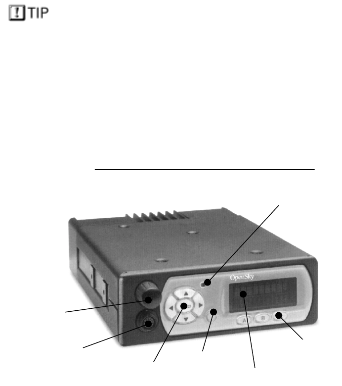
Front Panel Components
The front panel of your M-803 (or CH-103) includes
the Power Button/Speaker Volume Dial, the Micro-
phone/Speaker I/O Port, a 5-key “soft-button” keypad
for making menu selections, a 19-character vacuum
fluorescent Display Panel, 3 Mode Selector buttons, an
Emergency Button and an Ambient Light sensor.
Your Push-to-Talk button is located on your hand-held
detachable microphone or hands-free speaker box (not
shown here).
Because an M-803 mobile radio can support as many
as five Control Heads, your installation may or may
not include the hardware “box” behind the front panel.
The figure below shows the complete dash-mounted
configuration of an M-803 mobile radio complete with
front control panel.
Peripheral equipment such as a mobile computer or
data terminal connect to the M-803 through the rear-
panel peripheral interface.
Figure 4 Front Panel Components
Dash-Mount M-803 Standalone Configuration
Power and
V
olume Dial
Ambient Li
g
ht Senso
r
Mic/S
p
eaker
Connector
Menu and Selector Ke
yp
ad Emergency
Button Dis
p
la
y
Panel
Mode Selector
Button
s
Up to five Control Head
Units (CHU) can be
supported by a single
Mobile Radio Unit (MRU).
The most typical multiple
CHU configuration would
be a large fire truck or
other vehicle with a dash-
or trunk-mounted M-803
and auxiliary control heads
positioned elsewhere on
the vehicle.
CHAPTER 3—Controls and Indicators
22 M-803 Operator Manual Software Version OTP 5.07
Component Function
Power Button/..........
Volume Dial Push to Power Up.
Push again to Power Down.
Twist clockwise to increase
speaker volume.
Twist counter-clockwise to
decrease speaker volume.
Mic/Speaker.............
Connector Attach hand-held microphone,
hands-free speaker, or
keypad/microphone here.
Emergency ...............
Button In most setups, pressing this
button will send an emergency
alert and open voice commu-
nication with your default
emergency talkgroup.
Ambient Light..........
Sensor Radio automatically selects
Display Panel brightness level
based on ambient light. Do not
block this sensor.
Menu and .................
Selector Keypad Cycle through the menu loop
with Up and Down buttons.
Scroll through selections with
Left and Right buttons.
Press Select button to indicate
your final choice.
Display Panel ........... Menu selections appear here,
along with Signal Strength and
Volume indicators. User may
select which of several Dwell
Screens the radio will display.
Mode Selector ..........
Buttons Depending on setup choices
made by your Network
Administrator, you’ll use these
buttons to choose between
software mode presets.
Controls and Indicators—CHAPTER 3
Software Version OTP 5.07 M-803 Operator Manual 23
Peripheral Interface
The M-803 supports a variety of interfaces with its
flexible interconnect. The rear panel provides power
supply connectors and interfaces for both analog and
digital peripherals.
RS-232 Port
The serial RS-232 port operates in asynchronous
ASCII mode for configuration and control and switches
to Serial Line Internet Protocol (SLIP) mode for data
communication between the fixed network and a
mobile computer or terminal device.
I/O Connector
The I/O connector provides interfaces for an external
10 Watt speaker.
CAN 2.0 Bus
The rear panel also provides access to an industry
standard Control Area Network (CAN) 2.0 Bus for
reconfigurability and peripheral support.
Through the CAN port the M-803 in either dash- or
trunk-mounted installations can connect to as many as
5 Control Head Units (CH-103) or other CAN
peripherals such as public address. A terminator is used
if no CAN devices are used. The maximum length of
the CAN bus is 40 meters.
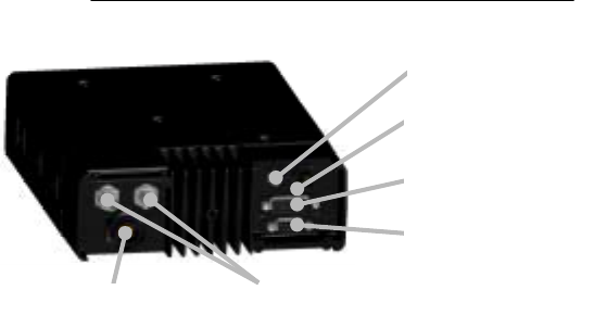
Hardware Connections
While day-to-day operations are conducted from the
front panel controls, the rear panel connectors will be
useful during installation, troubleshooting and
hardware upgrades.
CHAPTER 3—Controls and Indicators
24 M-803 Operator Manual Software Version OTP 5.07
Figure 5 Rear Panel Components
Connectors and Interfaces
Component Function
SER Connector................ Plug in your optional Mobil Data
Terminal (MDT) to this serial RS-232
port.
I/O Connector.................. Plug in your optional 10 Watt Speaker
to this port.
CAN Connector............... Connect up to five Control Heads (CH-
103) or other CAN devices such as
public address through this port.
GPS Connector................ Plug in your optional GPS antenna to
this port.
PWR Connector.............. Cables from the vehicle battery supply
power to the M-803 through this port.
Antenna Connectors ....... Plug in your radio antenna to these
ports. If the radio has the Full-Duplex
option, the radio will have both the
TxRx and Tx connectors, otherwise it
will have just the TxRx connector.
Full-duplex capability provides
increased data throughput performance.
Full-duplex is recommended when
using TCP/IP end user applications, or
sending messages longer than 1000
bytes using UPD/IP.
Antenna Connectors
GPS Connector
CAN Connector
SER Connector
I/O Connector
PWR Connecto
r

Controls and Indicators—CHAPTER 3
Software Version OTP 5.07 M-803 Operator Manual 25
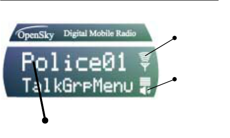
Display Screen Overview
The display screen shows the current status of your
radio setup. Signal strength and volume indicators
reside in the right-hand sector. The rest of the screen is
devoted to a 2-line Vacuum Fluorescent Display (VFD)
that changes in response to user interaction with the
Menu Selection buttons
• Signal Strength Icon (the 5-bar antenna icon) uses
three bars to indicate three levels of connectivity
strength and two bars to indicate the direction of
RF data. The directional bars “animate” upward to
indicate radio transmit, downward to indicate radio
receive.
• Speaker Volume Icon (looks like a speaker)
indicates user-selected speaker volume setting.
Twist the volume knob to change this setting.
• Selection Display (the top line of VFD text)
changes as you press the Left and Right menu
selector buttons to scroll through the selections in
the active menu loop.
• Menu Display (the bottom line of VFD text)
changes as you press the Up and Down menu
selector buttons to scroll through the menu loop.
• Dwell Display (the user-defined display default)
When not engaged in menu selection, the 2-line
VFD display defaults to the user-selected Dwell
Display. The top line shows the current Transmit
Talkgroup. The bottom line shows the user’s
choice of the current Profile, Channel, Caller or
Received Talkgroup.
The Figure below reflects just one of many possible
displays for a front panel display screen. There is no
pre-selected default screen for the OpenSky protocols.
Instead, each user will select the display condition of
his/her choice by making a choice from the Dwell
Display menu.
Users who fail to select a
dwell display will not
track channels, calls, or
profiles. Instead, the
screen will display the
most recent user menu
selection until another
menu choice is made.
CHAPTER 3—Controls and Indicators
26 M-803 Operator Manual Software Version OTP 5.07
After any Menu/Select procedure, your display screen
will revert to whatever display you have chosen as your
dwell display. Once the dwell display is active, it will
change dynamically to reflect the current profile, caller,
channel or received talkgroup.
Figure 6 Display Panel Elements
Sample Display
Component Function
Signal Strength .......
Icon Resident in every display screen.
As signal improves, more
“waves” appear. Waves animate
outward for Message Send,
inward for Message Receive.
Volume Icon............ Resident in every display screen.
Shows current speaker volume
setting chosen by the user.
Menu Selection .......
Display During a menu session the
bottom line responds to the Up
and Down menu buttons to show
the active menu (Talkgroup
Menu in this case). The top line
responds to the Left and Right
menu buttons to display the
options within that menu
(available Talkgroups within the
active profile in this example).
Si
g
nal
Strength
Indicator
V
olum
e
Indicator
Sam
p
le Dis
p
la
y
Screen showin
g
a Talk Group Menu session

Controls and Indicators—CHAPTER 3
Software Version OTP 5.07 M-803 Operator Manual 27
Dwell Displays
The M-803 Display Screen is highly interactive and
responds with a changing display in the upper and
lower text lines as the user presses the Menu Selection
buttons to scroll through the menu loop and the entries
under each menu.
When the button-pressing stops, though, the screen will
revert to the Dwell Screen and show the current status
of whichever category of information the user has
selected from the Dwell Display menu.
Dwell Display User-Selectable
The first line of any Dwell Display for Open Sky
trunked mode operation is always the currently active
Transmit Talkgroup for your selected profile. What
appears in the second line, though, depends on what
choice you make for your default display preference.
Whatever your preference, your radio will respond
dynamically to changes in status, always displaying the
current information about your network connection.
You may elect to have the screen display your current
Profile, current Channel name, current Caller, or
Received Talkgroup.
The figure below shows the choices available for dwell
display and some representative options available
under each menu heading. Setups vary widely from
network to network; don’t expect to find these actual
options in your menu.
Your Dwell Display
selection survives Power
Down for your User ID,
so whatever choice was
active during your
previous session is your
ad hoc default selection
the next time you Power
Up.

CHAPTER 3—Controls and Indicators
28 M-803 Operator Manual Software Version OTP 5.07
Figure 7 Dwell Display Hierarchy
Sample Setup
Profile Caller Received
Talkgroup Channel
TACTICAL
SOUTH
HIGHWAY
METRO
978240001
...40002
DISPATCH
No Caller
POLICE 01
DISPATCH
EMS 09
No Calls
OT450
OT460
0T550
OT999
Changing your Dwell Display choice is as simple as
any other menu selection operation. Your choice, once
made, persists until you change it again, even surviving
Power Down and re-provisioning procedures for your
User ID.
See the chapter on Display Screen Functions for step-
by-step instructions on how to select or change your
Dwell Display.
Sample Dwell Displays
Figures in the section below are merely illustrative of
how dwell displays might look in particular network
setups. You should not expect to see these exact text
selections in your own menu, which is prepared by
your network administrator to suit the particular needs
of your organization.
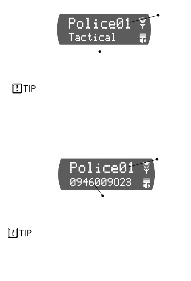
Dwell Display–Profile
If you select Profile as your Dwell Display, the upper
line of text will show the Transmit Talkgroup for the
active profile. The lower line of text will show the
name of the current profile.
Once selected, these displays will update to reflect user
interaction. Selecting a new profile will update both the
profile and the talkgroup fields to the current selection.
Profile is a largely
static Dwell Display. It
shows your current
profile and active
talkgroup, both of
which are static unless
overridden by user.
Controls and Indicators—CHAPTER 3
Software Version OTP 5.07 M-803 Operator Manual 29
Figure 8 Dwell Display—Profile
Sample Screen
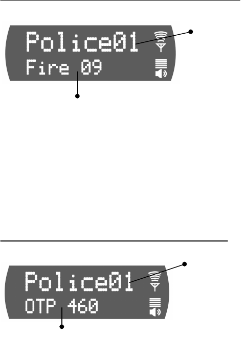
Dwell Display-Caller
If you select Caller as your Dwell Display, the upper
line of text will show the Transmit Talkgroup for the
active profile. The lower line of text will show the User
ID of the current caller.
Once selected, these displays will update dynamically.
Each new call you receive will change the bottom line
caller display. When no call is active, the bottom line
will display: No Caller.
Figure 9 Dwell Display—Caller
Sample Screen
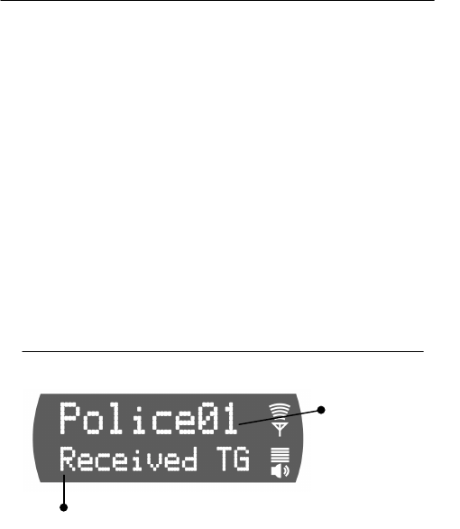
Dwell Display–Received Talkgroup
If you select Received Talkgroup as your Dwell
Display, the upper line of text will show the Transmit
Talkgroup for the active profile. The lower line of text
will show the Talkgroup of your incoming call.
Once selected, these displays will update dynamically.
Each new call you receive will change the bottom line
caller display. When no call is active, the bottom line
will display: No Calls.
Current
Transmit
Talkgroup
Current Profile
Curren
t
Transmit
T
alk
g
rou
p
User ID of Current Caller
With Caller as your
Dwell Display, the
identity of your current
caller updates
dynamically, but the
top line always shows
your current Transmit
Talkgroup.
With Received
Talkgroup as your
Dwell Display, the
Bottom Line updates
dynamically to display
your caller’s
Talkgroup, but the Top
Line is static.
CHAPTER 3—Controls and Indicators
30 M-803 Operator Manual Software Version OTP 5.07
Figure 10 Dwell Display—Received Talkgroup
Sample Screen
Dwell Display–Channel
If you select Channel as your Dwell Display, the
upper line of text will show the Transmit Talkgroup for
the active profile. The lower line of text will show your
currently tuned channel.
Once selected, these displays will update dynamically,
but the only way to alter the display would be to tune
in a new channel.
Figure 11 Dwell Display—Channel
Sample Screen
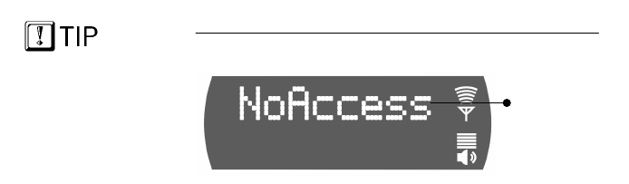
Dwell Display–No Access
No Access is not an option in the Dwell Display menu.
It’s a default message your screen will display
whenever your radio cannot make contact with the
OpenSky network.
Current
Transmit
T
alk
g
rou
p
T
alk
g
rou
p
of Incomin
g
Caller
Current
Transmit
T
alk
g
rou
p
Currentl
y
Tuned Channel
Controls and Indicators—CHAPTER 3
Software Version OTP 5.07 M-803 Operator Manual 31
Figure 12 Display Screen—No Access
Sample Screen
You can wait for the condition to clear, or, if an off-
network mode of operation will temporarily suit your
needs, navigate to the Mode Menu and select a
conventional radio mode.
Radio
unable to
make
Network
connection
From the No Access
screen there’s no
indication of which
choice you’ve made for
Dwell Display.
CHAPTER 3—Controls and Indicators
32 M-803 Operator Manual Software Version OTP 5.07
Display Panel Functions—CHAPTER 4
Software Version OTP 5.07 M-803 Operator Manual 33
CHAPTER 4
Display Screen Functions
Menu and Selector Keypad 34
User-Selectable Menu Operations 34
Keypad Navigation 34
Select Dwell Display 35
Select Operational Mode 36
Universal Connectivity 37
Duration of Mode Change 38
Select Profile 39
Check or Change Active Profile Status 40
Select Talkgroup 41
Check or Change Active Talkgroup 41
Prioritizing a Talkgroup 43
Duration of Priority Assignments 44
Lock Out Talkgroup 44
Groups You Can Lock Out 45
Caution Regarding Profile Changes 48
Select Scan Mode 48
Check or Change Active Scan Mode 49
Duration of Scanning Mode Selections 50
Select Channel 51
Enable/Disable Side Tones 52
Select Brightness Setting 53
CHAPTER 4—Display Panel Functions
34 M-803 Operator Manual Software Version OTP 5.07
Menu and Selector Keypad
Display Screen functions are launched from the Menu
and Selector Keypad. Most user-selectable radio
operations are conducted by using the keypad to make
selections from the operations menus.
User-Selectable Menu Operations
You’ll use the keypad for mundane chores like
adjusting your display screen brightness, and for
critical operations like establishing your operational
mode and setting your active profile. Below is a list of
menu options.
Keypad-Accessible Menu Operations
• Set your Operations Mode:
OpenSky Trunked, Conventional, Over-the-Air
Download, or Coverage
• Set your Active Profile
• Set your Priority Talkgroup
• Lockout any Talkgroup
• Set your Scanning Mode
Normal, Talkback, or No Scan
• Select a Channel from the preset Channel Menu
• Set your Dwell Display
• Enable or Disable Audible Side Tones
• Change Brightness Setting of your Display Screen
Keypad Navigation
With a few exceptions that will be discussed in specific
sections below, the same basic steps will suffice for all
menu selection procedures. In general, selecting a new
menu option setting is a 3-step process:

Display Panel Functions—CHAPTER 4
Software Version OTP 5.07 M-803 Operator Manual 35
1.) Repeatedly Press the Up or Down key to cycle
through the list of available Menu headings. When
the Menu you want appears in the Top line of the
Display Screen . . .
2.) Repeatedly Press the Left or Right key to cycle
through the list of available options for the Menu.
When the option you want appears in the Bottom
line of the Display Screen . . .
3.) Press the Select button to lock in your choice.
When the M-803 accepts your choice, the display
screen will revert to the user-selectable Dwell Display
you’ve chosen.
Select Dwell Display
There is no specific “default screen” for the M-803.
Rather, there are several user-selectable options for the
categories of feedback the radio will display during
operation. See the Getting Started chapter for a full
discussion of your dwell display options.
The first line of any Dwell Display for Open Sky
trunked mode operation is always the currently active
Transmit Talkgroup for your selected profile.
What appears in the second line, though, depends on
what choice you make from the Dwell Display Menu
for your default display preference.
In short, you’ll use the menu buttons to establish your
own default screen, depending on whether you want
your radio to display the current Profile, the Channel,
your current Caller, or your current caller’s Talkgroup.
If you’re happy with the
dwell display when your
radio Powers Up, do
nothing. You only need to
change your Dwell Display
to get information the radio
is not already providing.
CHAPTER 4—Display Panel Functions
36 M-803 Operator Manual Software Version OTP 5.07
Ø How to set your Dwell Display
Selection
1.) If the top line of your display screen shows the
Transmit Talkgroup for your selected profile,
you’re ready to begin.
2.) Use the Left and Right buttons to cycle through
the Dwell Menu options in the lower line of the
display screen: Profile, Caller, Channel, Received
Talkgroup.
3.) Press the Select button to lock in your choice.
Your selected Dwell Display will appear as soon as the
M-803 accepts your choice.
Figure 13 Dwell Display Selection
Sample Screen
Component Explanation
Transmit..............
Talkgroup The first line of any Dwell Display
is the active talkgroup for your
current profile.
Menu Option....... Choose Caller, Profile, Channel or
Received Talkgroup. For every call
you receive, your radio will
identify your caller’s talkgroup.
Select Operational Mode
The M-803 is a “soft” radio, designed to operate under
a variety of software-enabled, user-selectable
operational modes. Under most work conditions, you’ll
Currently
Active
Transmit
Talkgroup for
your Profile
Available Dwell Display: Received Talkgroup

Display Panel Functions—CHAPTER 4
Software Version OTP 5.07 M-803 Operator Manual 37
operate your radio as a fully-networked component of
the OpenSky digital network and carry on rich-featured
communications with similarly networked agencies or
subscribers.
At startup, your M-803 automatically selects the
OpenSky Trunked Protocol (OTP) to provide the full
range of features available on your digital voice and
data network.
On the other hand, if your agency cooperates with
several others in a multi-agency network supported by
OpenSky’s IP backbone, all agencies benefit from the
advantages of the network architecture whether or not
they’ve migrated from older analog equipment to
digital OpenSky radios.
For those occasions when you need to communicate
with radios using older protocols (such as conventional
FM), you can manually change your radio’s operating
mode.
Universal Connectivity
When conditions require it, you can re-configure your
M-803, with a simple menu selection, to access
conventional CTCSS analog FM or APCO Project 25
CAI operations. This is especially helpful when you
need to communicate with users from other agencies or
fleets not completely integrated with OpenSky.
• The principle operating mode currently in use is
the OpenSky Trunked Protocol (OTP). Choose
OTP for full-featured communications with other
digital equipment connected to the OpenSky
network.
• From the Mode Selection Menu, you can also
access OpenSky Conventional FM (OCF) with
Continuous Tone Coded Squelch System
(CTCSS).
• When your Network Administrator initiates a mid-
shift Personality Upgrade or Dynamic Regrouping,
you’ll engage the Over-the-Air Download mode.
Your only indication
that you have logged
on to the network is
the name of your
Talkgroup in the Dwell
Display.

CHAPTER 4—Display Panel Functions
38 M-803 Operator Manual Software Version OTP 5.07
• If you stray outside the network’s strong coverage
area and require an off-network conventional radio
connection, select Coverage mode to temporarily
improve your capabilities.
To protect against inadvertent or too-hasty mode
changes, the M-803 software will force a confirmation
sequence before accepting your new selection.
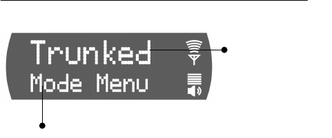
Ø How to set your Operational Mode
1.) Use the Up and Down buttons to cycle through
the menu choices until Mode Menu appears.
2.) Use the Left and Right buttons to cycle through
the Mode Menu options: Trunked, Conventional,
Over the Air Download, or Coverage.
3.) Press the Select button to activate the fail-safe
Confirmation process.
4.) Use the Left and Right buttons to cycle through
the confirmation options: Confirm?Y to make the
change; Confirm?N to abort the change.
5.) Press the Select button to lock in your choice.
6.) The display panel will flash the confirming
message: BOOTING and your radio will
reconfigure itself to operate in the Mode you
selected.
Duration of Mode Change
Mode change is a major operational commitment. It
requires a Power Down and Reboot operation which
Display Panel Functions—CHAPTER 4
Software Version OTP 5.07 M-803 Operator Manual 39
the radio itself will undertake when you press the
Select button to confirm a mode change.
At Power Up, your radio automatically adopts the
operating mode of its previous use. Any changes you
make to the mode during your shift will remain in
effect until you make another selection and Reboot.
Figure 14 Operational Mode Menu
Sample Display
Component Explanation
Mode Menu ......... Determines whether your radio
will operate as conventional analog
equipment, or a fully-functioning
digital OpenSky radio.
Menu Option ....... When you access the Menu, the
currently selected option appears in
the option line. To change, scroll to
a new option and press the Select
button.
Select Profile
When you Power Up your radio at the beginning of a
shift, your M-803 is provisioned by the network with a
radio personality composed of as many as 16 profiles,
one of which your network administrator has
designated as your Active Profile by default.
Your default profile will contain your most common
talk group and as many as 16 other user groups the
radio treats as “listen groups.”
Menu Option:
OpenSky
Trunked
Protocol
A
ctive Menu: O
p
erational Mod
e

CHAPTER 4—Display Panel Functions
40 M-803 Operator Manual Software Version OTP 5.07
Each of your other profiles, if any, is another group of
as many as 16 more user groups, one of which is
always the default Talkgroup. See the Getting Started
chapter for a full discussion of user groups, profiles,
listen groups, talkgroups and radio personality.
If you need access to groups not part of your active
profile, you can use the Menu Selector Buttons to
access the Profile menu and switch to any other pre-set
menu that is part of your radio personality.
You’ll have to be familiar enough with your profiles to
know which user groups are organized under each
name. Or, if just want to access a new talkgroup, you
can tune in the profile for which the talkgroup you
want to access is the default.
Check or Change Active Profile Status
If your Dwell Display is set to Profile, your screen will
display your active profile at all times. Otherwise, to
see your current selection, use the Menu Selector
keypad to access the Profile Menu.
To switch to a new active Profile during your work
shift, access the Profile Menu from the Menu Selector
keypad and make a new selection from the options.
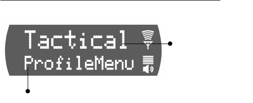
Ø How to set your Active Profile
1.) Use the Up and Down buttons to cycle through
the Menu choices until ProfileMenu appears.
2.) Use the Left and Right buttons to cycle through
the Profile Menu options established by your
Network Administrator.
3.) Press the Select button to lock in your choice.
Your selected Dwell Display will appear as soon as the
M-803 accepts your choice.
It’s a good idea to
know the default
Talkgroup for each
Profile in your
Personality so you can
access it easily from
the Profile Menu.
Display Panel Functions—CHAPTER 4
Software Version OTP 5.07 M-803 Operator Manual 41
Figure 15 Profile Selection Menu
Sample Display
Component Explanation
Profile Menu........ Determines which group of up to
16 user groups will be your active
Profile.
Menu Option ....... When you access the Menu, the
currently selected Active Profile
appears in the option line. To
change, scroll to a new Profile and
press the Select button.
Select Talkgroup
Only one of the up to 16 user groups in your active
Profile is configured as a Talkgroup. The others, as
determined by the Network Administrator, are listen
groups. You will receive voice calls from the listen
groups, but you can only instigate voice calls with
them by assigning them Talkgroup status.
You can reply to incoming voice calls if your radio is
operating in Talkback Scan Mode, but you cannot
instigate these calls. See Scan Mode for more details.
Check or Change Active Talkgroup
If your Dwell Display is set to Profile, your screen will
display your active profile and your Transmit Talk-
group at all times. Otherwise, to see your current
Menu O
p
tion:
Sample Profile
from your
Personality
Dwell Dis
p
la
y
A
ctive Menu: Profile Selectio
n
CHAPTER 4—Display Panel Functions
42 M-803 Operator Manual Software Version OTP 5.07
selection, use the Menu Selector keypad to access the
Profile Menu.
To assign Talkgroup status to a new user group during
your work shift, access the Talkgroup Menu from the
Menu Selector keypad and make a new selection from
the options.
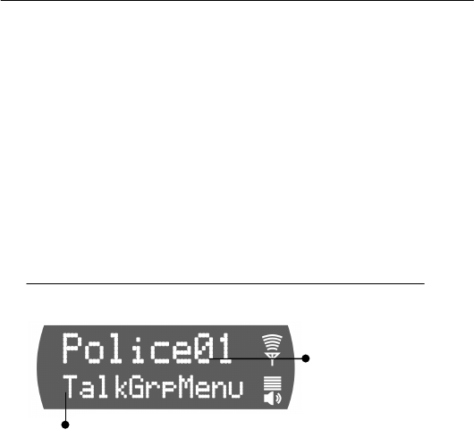
Ø How to set your Active Talkgroup
1.) Use the Up and Down buttons to cycle through
the Menu choices until TalkGrpMenu appears.
2.) Use the Left and Right buttons to cycle through
the list of user groups in your Active Profile, as
established by your Network Administrator.
3.) Press the Select button to lock in your choice.
Your selected Dwell Display will appear as soon as the
M-803 accepts your choice.
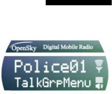
Figure 16 Talkgroup Selection Menu
Sample Display
Component Explanation
Talkgroup Menu....... Determines which of up to 16 user
groups will be your Talkgroup.
Menu Option............. When you access the Menu, the
currently active Talkgroup appears
in the option line. To change, scroll
to a new user group and press the
Select button.
Menu Option:
Sample User
Group from your
Active Profile
A
ctive Menu: Talk
g
rou
p
Selectio
n

Display Panel Functions—CHAPTER 4
Software Version OTP 5.07 M-803 Operator Manual 43
Prioritizing a Talkgroup
At different times during your shift you may want to
improve your radio’s sensitivity to incoming calls from
a particular user group. If you make no such changes
during a radio use session, the Default Talkgroup for
each profile will maintain automatic scanning priority
over all other user groups in the profile.
Increasing the scanning priority of a group other than
the Default Talkgroup improves your receptiveness to
that group’s calls compared to all the other groups in
your active profile, including the Default Talkgroup.
You may use the procedure below to establish one new
priority scanning group for every profile in your radio
personality. There’s no ranking order in scanning
priority: one group per profile is the priority group; all
other groups in the same profile are “non-priority.”
Ø How to Assign Priority to a
Talkgroup
1.) Use the Up and Down buttons to cycle through
the Menu choices until PriTGMenu appears.
2.) Your display screen shows PriTGMenu in the
bottom line and the current Priority Scan group in
the top line.
3.) Use the Left and Right buttons to cycle through
the list of user groups in your selected Profile,
until the group you want to assign Priority
Talkgroup status appears onscreen.
4.) Press the Select button to lock in your choice.
Your selected Dwell Display will appear as soon as the
M-803 accepts your choice.
Priority Scan is
different from
Talkgroup status.
Even if you give a
user group Priority
Scan status, your
Talkgroup is still your
Talkgroup.

CHAPTER 4—Display Panel Functions
44 M-803 Operator Manual Software Version OTP 5.07
Figure 17 Priority Talkgroup Menu
Sample Screen
Component Explanation
Priority......................
Talkgroup Menu When this menu is active, the Left
and Right buttons will scroll you
through the user groups in your
selected profile.
Menu Option............. Scroll through groups and use the
Select button to confirm the group
you wish to make your temporary
Talkgroup.
Duration of Priority Assignments
If you make no priority assignments during your shift,
each profile selects the Default Talkgroup as the
priority scan group. When you use the Priority Scan
menu to assign scanning priority to a new group, your
assignment stays in effect until you change it or turn
your radio off. Powering Off erases all scanning
priority assignments and resets your radio to the
defaults.
Lock Out Talkgroup
There are at least two ways to focus your voice
communications by suppressing calls from user groups
in your active profile.
• No Scan. By changing your Scanning Mode to
NOSCAN you can block all non-emergency voice
calls from the “listen groups” in your profile,
Menu Option:
Sample User
Group from your
Active Profile
Active Menu: Priority Talkgroup Menu

Display Panel Functions—CHAPTER 4
Software Version OTP 5.07 M-803 Operator Manual 45
concentrating your attention entirely on your
Default, Selected or Priority Talkgroup.
• Lock Out. By locking out selected Talkgroups,
you can eliminate just the background “noise” you
select, focusing your scanning resources on just the
groups whose calls you wish to track.
Emergency calls will cut through your lock-out
command, but you won’t be distracted by the other
voice call activity from user groups you’ve locked out,
until you elect to run the menu again and remove the
lock.
Groups You Can Lock Out
• Active Profile. It stands to reason that only groups
in your active profile can be locked out, since
they’re the only groups whose voice calls you’ll
hear. The Lockout menu responds to incoming
voice call activity, loading the names of calling
groups into the menu as the calls are received.
• Received Call Menu. If you don’t find a name
you’re looking for in the Lockout menu, either it’s
not in your active profile, or you haven’t received
a call from that group yet in this radio session.
Until you do take a call from that group, you can’t
lock them out.
To protect against inadvertent or too-hasty Lockout
procedures, the M-803 software will force a
confirmation sequence before accepting your new
selection.
Ø How to Lock Out a Listen Group
1.) Use the Up and Down buttons to cycle through
the Menu choices until LockOutMenu appears.
2.) Your display screen shows LockOutMenu in the
bottom line and, in the top line, the name of a user
group from your active profile you’ve received a
voice call from since Powering Up.
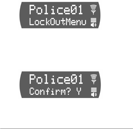
CHAPTER 4—Display Panel Functions
46 M-803 Operator Manual Software Version OTP 5.07
3.) If the word NONE appears in the top line, you
haven’t received any voice calls from user groups
in this profile, so Lock Out is not an option.
4.) Use the Left and Right buttons to cycle through
the list of candidates, if any, until the user group
you want to Lock Out appears onscreen.
5.) Press the Select button to activate the fail-safe
Confirmation process.
6.) Use the Left or Right button to cycle through the
confirmation options: Confirm?Y to lock out the
group; Confirm?N to remove a lock.
7.) Press the Select button to confirm your choice.
Your selected Dwell Display will appear as soon as the
M-803 accepts your Lockout choice.
Ø How to Unlock a Listen Group
1.) Use the Up and Down buttons to cycle through
the Menu choices until LockOutMenu appears.
2.) Your display screen shows LockOutMenu in the
bottom line and, in the top line, the name of a user
group from your active profile you’ve received a
voice call from since Powering Up.
3.) If the word NONE appears in the top line, you
haven’t received any voice calls from user groups
in this profile, so Lock Out is not an option.
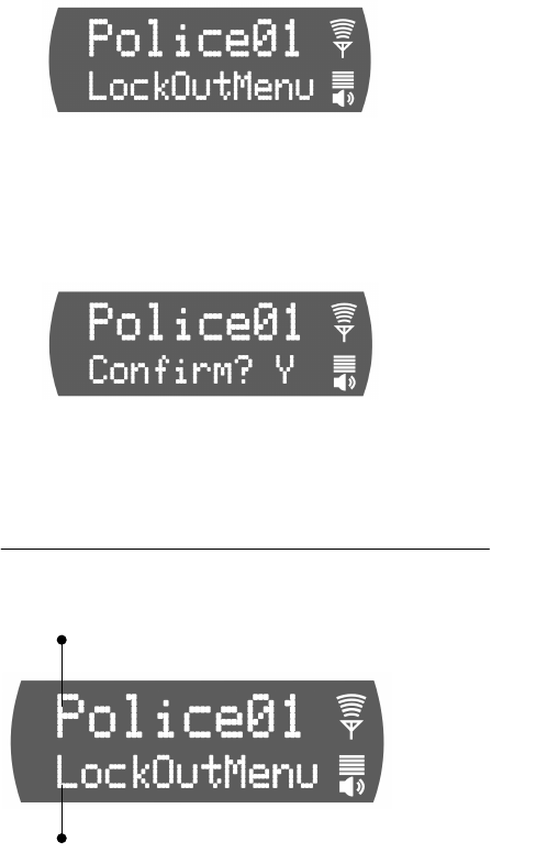
Display Panel Functions—CHAPTER 4
Software Version OTP 5.07 M-803 Operator Manual 47
4.) Use the Left and Right buttons to cycle through
the list of candidates, if any, until the user group
you want to Unlock appears onscreen.
5.) Press the Select button to activate the fail-safe
Confirmation process.
6.) Use the Left or Right button to cycle through the
confirmation options: Confirm?Y to lock out the
group; Confirm?N to remove a lock.
7.) Press the Select button to confirm your choice.
Your selected Dwell Display will appear as soon as the
M-803 accepts your Unlock choice.
Figure 18 Lock Out Menu
Sample Screen
Component Explanation
Menu Option ....... As you scroll through the user groups
in your active profile, notice they
only appear in the Lock Menu if you
Active Menu: Lockout Talkgroup
Menu Option: User Groups from active
p
rofile that have called
y
ou this session.
CHAPTER 4—Display Panel Functions
48 M-803 Operator Manual Software Version OTP 5.07
have received a voice call from them
since Powering Up.
Lock Out .............
Talkgroup Both Locked-Out and Not-Locked
groups appear in the Menu. You
can’t confirm the status of any group
except by pressing the Select button
to enter the Confirmation cycle.
Caution Regarding Profile Changes
Talkgroup Lockout status does not survive a change of
Profile. If you need to select a new Profile after taking
the time to Lockout several talkgroups from your
current profile, understand that making the change will
Unlock all groups.
Compare your options before changing your profile. If
you can achieve your goal by temporarily assigning
Priority Talkgroup status to a user group, you may be
able to avoid having to lock out the same groups twice.
Select Scan Mode
Three scanning modes are available for the M-803, but
only one can be active at any time. Changing your
scanning mode changes the way your radio scans voice
calls for all of the profiles in your radio personality, no
matter which profile is or becomes active.
Your choice of scanning mode will broaden or narrow
the span of your communications with all the listen
groups in your profiles, but does not affect your
interaction with your talk groups.
Your scanning mode choice will stay in effect until you
change it again; even if you turn off your radio, your
current selection will be saved until your next use.
Scan Mode Explanation
No Scanning...... Eliminates distractions.
Full communications (listen and
talk) with your talk group.
Display Panel Functions—CHAPTER 4
Software Version OTP 5.07 M-803 Operator Manual 49
No calls from listen groups.
Normal ..............
Scanning This is the default setting.
Network administrator has
established this as the most effective
configuration for everyday use.
Full communications (listen and
talk) with your talk group.
Receive calls from the listen groups.
Talkback............
Scanning Place talkback voice calls to the
most recent listen group by pressing
the Push-to-talk button before the
Talkback timer expires.
Full communications (listen and
talk) with your talk group.
Receive calls from the listen groups.
Check or Change Active Scan Mode
The Dwell Display screens do not show active Scan
Mode status. To see your current selection, use the
Menu Selector keypad to access the Scan Mode Menu.
The scan mode status displayed in the top line of the
screen display is your active status.
To change scan mode during your work shift, access
the Scan Mode Menu from the Menu Selector keypad
and make a new selection from the options available.
• To narrow your scanning list to just the talk group
in your active profile, choose No Scan from the
Scan Menu.
• To select the default scanning mode which scans
all the listen groups in your active profile, choose
Normal from the Scan Menu.
• To broaden your communications range by
enabling talkback voice calls to your active listen
groups, choose Talkback from the Scan Menu.
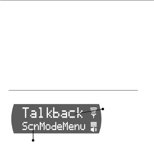
CHAPTER 4—Display Panel Functions
50 M-803 Operator Manual Software Version OTP 5.07
Ø How to set your Scan Mode
1.) Use the Up and Down buttons to cycle through
the Menu choices until ScnModeMenu appears.
2.) Use the Left and Right buttons to cycle through
the list modes until your choice appears: Normal,
Talkback or No Scan.
3.) Press the Select button to lock in your choice.
Your selected Dwell Display will appear as soon as the
M-803 accepts your choice.
Figure 19 Scan Mode Menu
Sample Display
Component Explanation
Scan Mode Menu...... Determines whether you will scan
or suppress your listen groups for
incoming voice messages. Enables
or disables Talkback to your most
recent caller.
Menu Option............. When you access the Menu, the
currently active Scan Mode
appears in the option line. To
change, scroll to a new mode and
press the Select button.
Duration of Scanning Mode Selections
Scanning Mode selections survive Power Down. At
startup, your radio will default to the scanning mode of
your last use. Any selection you make during your shift
will remain in effect until you make a new selection
from the Scan Mode menu.
Menu
Option:
One of three
available
Scan Mode
s
Active Menu: Scan Mode Menu
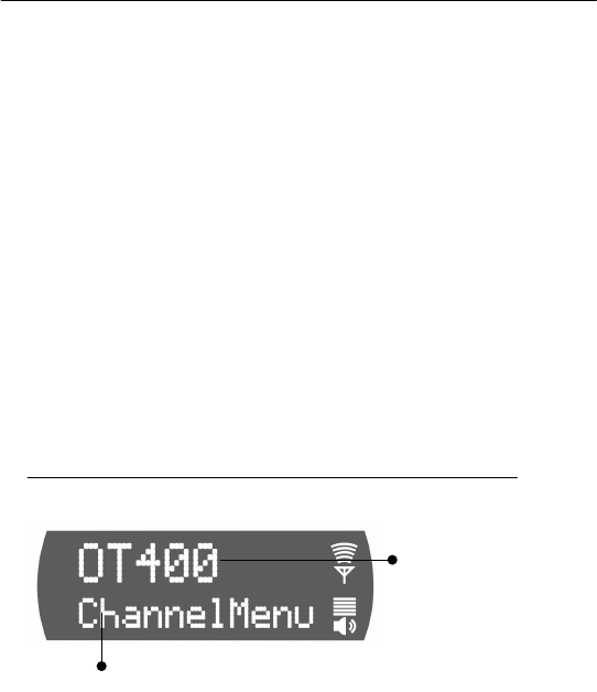
Display Panel Functions—CHAPTER 4
Software Version OTP 5.07 M-803 Operator Manual 51
Select Channel
If your reception is poor or you are repeatedly denied
channel access, you can manually change the radio to a
different channel. When you use the menu buttons to
choose Channel, the M-803 adjusts to show you the
first of the available channels from which you may
choose.
Ø How to Change the Channel
1.) Use the Up and Down buttons to cycle through
the Menu choices until ChannelMenu appears.
2.) Use the Left and Right buttons to cycle through
the pre-sets until the channel you want appears
onscreen.
3.) Press the Select button to lock in your choice.
Your selected Dwell Display will appear as soon as the
M-803 accepts your choice. If your active Dwell
Display is Channel, your newly selected channel name
will appear in the display panel (along with the active
talkgroup) as soon as it tunes in. Otherwise, you’ll have
to access the Channel Menu again to check your
channel.
Figure 20 Channel Change Menu
Sample Screen
Component Explanation
Channel Menu.......... Used to tune in any available pre-
set channel from the menu.
Menu
Option:
A
vailabl
e
Active Menu: Channel Selection

CHAPTER 4—Display Panel Functions
52 M-803 Operator Manual Software Version OTP 5.07
Menu Option............. When you access the Menu, the
first available channel appears in
the option line. To change, scroll
through the pre-sets and confirm
your choice with the Select button.
Enable/Disable Side Tones
Your radio sounds confirming tones when you press
the Menu or Selector buttons. Most users find this
audible confirmation helpful in navigating the menus in
the Display Panel.
Turning off your radio
does not affect your Side
Tone setting, which will
be saved for your next
use.
You can disable the side tones, if you wish, by
navigating to the Side Tone menu, and selecting Off.
To re-enable the tones, you’ll need to navigate back to
the same menu (without the benefit of side tones) and
this time select On.
For covert operations, it is important to be able to turn
off the audible side tones that occur when you press a
Menu or Selector button. For safety’s sake, though, you
probably won’t want to shut your radio down for the
time you’re planning to go covert.
To temporarily disable the tones that could expose your
presence and position, use the Menu Selector buttons to
access the Side Tone Menu. There are only two choices
in the Side Tone Menu (On, Off).
If your radio is operating properly but you don’t hear
tones when you press the Menu or Select buttons, your
side tones are probably disabled. Access the Side Tone
menu and reset your Tones to On.
Ø How to Enable or Disable Side Tones
1.) Use the Up and Down buttons to cycle through
the Menu choices until SideMenu appears.
2.) Use the Left or Right button to change the
display from On to Off or vice versa.
3.) Press the Select button to lock in your choice.

Display Panel Functions—CHAPTER 4
Software Version OTP 5.07 M-803 Operator Manual 53
Your selected Dwell Display will appear as soon as the
M-803 accepts your choice.
Figure 21 Side Tones Menu
Sample Screen
Component Explanation
Side Tones Menu...... Used to tune in any available pre-
set channel from the menu.
Menu Option ............ When you access the Menu, the
screen will indicate whether your
sidetones are On or Off. To change
the setting, press the Left or Right
button and confirm your choice
with the Select button.
Select Brightness Setting
Your M-803 uses a front-panel light sensor to adjust
the display to ambient light conditions. However, the
Brightness Selection gives users some control over the
screen display.
There are only three choices in the Brightness Menu.
You’ll use the menu in high- or low-light situations to
make the screen one step Brighter or Dimmer than the
current (Nominal) setting.
Ø How to Change Screen Brightness
1.) Use the Up and Down buttons to cycle through
the Menu choices until Bright Menu appears.
Menu
Option: Side
Tones On or
Off
A
ctive Menu: SideTones On/Off
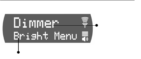
CHAPTER 4—Display Panel Functions
54 M-803 Operator Manual Software Version OTP 5.07
2.) Use the Left button to change the display from
Nominal to Dimmer, or the Right button to
change the display to Brighter.
3.) Press the Select button to lock in your choice.
Your selected Dwell Display will appear as soon as the
M-803 accepts your choice. Your display screen should
be immediately brighter or dimmer as you requested.
Figure 22 Brightness Selection Menu
Brightness Selection Menu
Component Explanation
Brightness Menu....... Used to change screen display one
increment brighter or dimmer than
the automatic (nominal) setting.
Menu Option............. When you access the Menu, the
screen will indicate Nominal.
Change to Brighter or Dimmer,
and confirm your choice with the
Select button.
Menu
Option:
Display
Screen
Bri
g
htnes
s
Active Menu: Brightness Selection
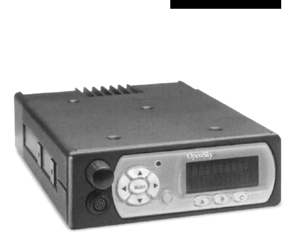
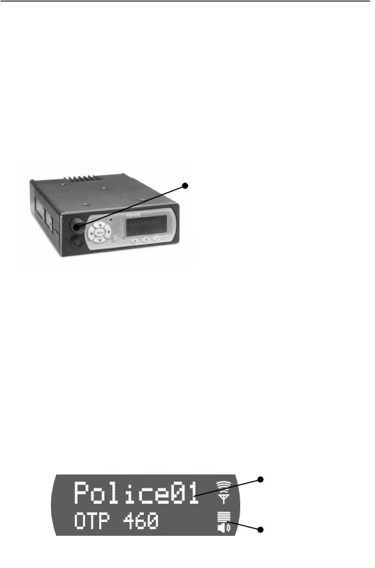
CHAPTER 5—Basic Radio Operations
56 M-803 Operator Manual Software Version OTP 5.07
Power Up
Power Up, Power Down, and Volume functions are all
handled from the Power Button/Volume Dial, a front
panel component.
Ø How to Turn Your Radio On
1.) Push the Power Button/Volume Dial. Your
radio’s vacuum fluorescent display panel will glow
to indicate Power Up.
2.) If required by the radio network, use the Mobile
Data Terminal (MDT) Keyboard to enter your
User ID. If your system doesn’t require a Log-On,
the radio proceeds through the Startup Sequence.
3.) Wait through the Startup Sequence, which lasts
approximately 10 seconds.
During this time your radio is provisioned with
your customized radio personality, emergency
conduct and user specifications, all designed for
your specific needs by the Network Administrator
and prompted by your User ID.
4.) When provisioning is complete, the M-803 will
display your last-saved Dwell Display in the front
panel Display Screen.
Power Button /
Volume Dial
User-Selected
Dwell Dis
p
la
y
Current
Volume
Setting
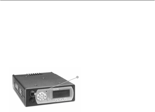
Basic Radio Operations—CHAPTER 5
Software Version OTP 5.07 M-803 Operator Manual 57
Log-On
If the radio network requires a Log-On, pushing the
Power Button/Volume Dial will supply power to your
radio, but will not connect it to the OpenSky network.
Your radio will not boot and provision itself until you
use the MDT keyboard to log on with your User ID.
Even if you want to use your radio for non-network
traditional RF communications, you’ll still need to log
on to the network first, then select Talkaround Mode to
work off-network.
Ø How to Log On to the Network
1.) Push the Power Button/Volume Dial. Your
radio’s vacuum fluorescent display panel will glow
to indicate Power Up.
2.) If required by the radio network, use the Mobile
Data Terminal (MDT) Keyboard to enter your
User ID. If your system doesn’t require a Log-On,
the radio proceeds through the Startup Sequence.
3.) Wait through the Startup Sequence, which lasts
approximately 10 seconds.
During this time your radio is provisioned with
your customized radio personality, emergency
conduct and user specifications, all designed for
your specific needs by the Network Administrator
and prompted by your User ID.
Power Button /
Volume Dial
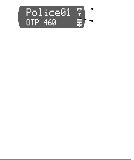
CHAPTER 5—Basic Radio Operations
58 M-803 Operator Manual Software Version OTP 5.07
4.) When provisioning is complete, the M-803 will
display your last-saved Dwell Display in the front
panel Display Screen.
Self-Test
After Power Up and your M-803 radio undergoes a
multi-function automatic Boot procedure.
• Your radio is “provisioned” with your radio
personality: as many as 16 radio profiles are
downloaded to your equipment from the network
in response to your User ID.
• Emergency behavior is provisioned along with
each profile.
• Your radio conducts a diagnostic Built-In Self-Test
(BIST).
The Self-Test is a battery of hardware diagnostic tests
on the internal components of the Mobile Radio Unit.
All processor and memory elements, interfaces,
connectivity elements and RF functionalities are
diagnosed for operational integrity.
Ø How to Read the Self-Test Results
1.) The BIST (Built-In Self-Test) is automatic on
Power Up.
2.) . . . BIST PASS. If all components, elements,
interfaces and functionalities test OK, the M-803
will deliver a PASS message to the front panel
Display Screen.
User-Selected
Dwell Display
Current
Volume
Setting
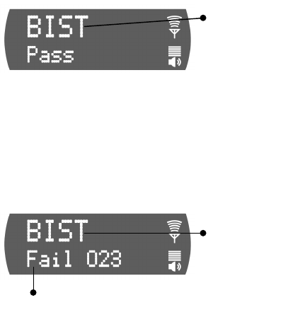
Basic Radio Operations—CHAPTER 5
Software Version OTP 5.07 M-803 Operator Manual 59
3.) The PASS message remains onscreen briefly, then
yields to the last-saved Dwell Display for the
logged-on radio subscriber.
4.) . . . BIST FAIL. If a radio component, element,
interface or functionality fails the diagnostic test,
the M-803 will deliver a FAIL message to the
front panel Display Screen.
5.) . . .If the Self-Test detects a Fatal operational
error, the FAIL message and Error Code will
remain on screen. Log-on will not proceed.
6.) . . .If the Self-Test reveals a Nonfatal failure, the
FAIL message and Error Code remain onscreen
long enough for the user to record, then yields to
the last-saved Dwell Display for the logged-on
User ID.
7.) To force a re-test, or to get another look at the
Error Code, first Power Down, then Power Up.
Power Down
Power Up, Power Down, and Volume functions are all
handled from the Power Button/Volume Dial, a front
panel component.
Built-I
n
Self Test:
Passed all
tests
Self Test
Failure
Message
Self-Test Error Cod
e
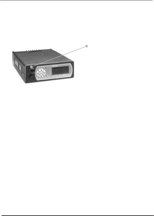
CHAPTER 5—Basic Radio Operations
60 M-803 Operator Manual Software Version OTP 5.07
Ø How to Turn Your Radio Off
1.) Push the Power Button/Volume Dial. Your
radio’s vacuum fluorescent display panel will fade
to darkness to indicate Power Down.
2.) Several user-selected radio settings, including your
current Dwell Display, will survive the Power
Down procedure.
3.) At your next Power Up, these saved settings will
automatically default, along with your network
personality settings.
Set Volume
Power Up, Power Down, and Volume functions are all
handled from the Power Button/Volume Dial, a front
panel component.
Your radio’s front panel Display Screen always
displays the current volume, whether you are receiving
an active call or not.
Ø How to Change the Volume
1.) Rotate the Power Button/Volume Dial clockwise
to increase the Speaker Volume, counter-
clockwise to decrease the Speaker Volume.
Power Button /
Volume Dial
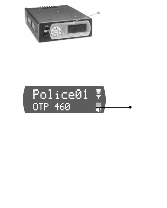
Basic Radio Operations—CHAPTER 5
Software Version OTP 5.07 M-803 Operator Manual 61
2.) Whether you are receiving a voice call or not, your
volume setting change will immediately reflect in
the front panel display screen Speaker Volume
indicator.
Voice Calls
As soon as your radio completes the Startup/Log
On/Provision/Self-Test sequence and goes live on the
OpenSky network, you’ll begin to hear voice calls from
the talk and listen groups in your active profile.
No action is required on your part, but the following
list details how your radio responds to incoming voice
messages.
Ø How to Take a Voice Call
1.) . . . If your Dwell Display is set to Caller, your
front panel display screen shows the User ID of
the incoming caller.
2.) . . . If your Dwell Display is set to Received
Talkgroup, your front panel display screen shows
the talkgroup to which your incoming caller
belongs.
3.) . . . If your Dwell Display is set to Profile or
Channel, your front panel display screen shows
the data appropriate to those displays, but provides
no clue to the identity of your incoming caller.
Power Button /
Volume Dial
S
p
eaker Volum
e
Indicator
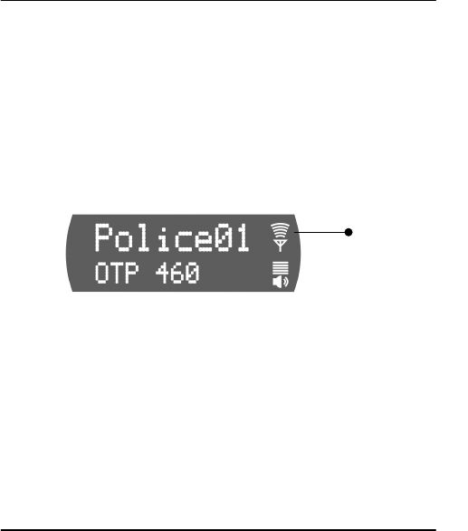
CHAPTER 5—Basic Radio Operations
62 M-803 Operator Manual Software Version OTP 5.07
4.) Regardless of your active Dwell Display, the
display screen’s Signal Strength Indicator glows
brightly for a strong signal from the incoming
caller, dimly for a weak signal.
The steps for making a voice call are similar to those
for a conventional portable radio.
Ø How to Make a Voice Call
1.) First, if you haven’t already, Power Up your radio
by pressing the Power Button/Volume Dial to
Power Up, and Log On with your User ID. (See
How to Turn Your Radio On.)
2.) Check the Signal Strength indicator light for
clearance. If the light is burning brightly, you are
receiving a call.
3.) Wait for clearance if necessary. A single End of
Message tone will indicate the end of your
incoming call.
4.) Depress and hold the Push-to-Talk button on your
remote hand-held microphone and speak normally.
For maximum clarity, hold the transceiver
approximately 1½ inches from your mouth.
5.) Release the Push-to-Talk button to terminate your
outgoing voice call.
Ø What the Beeping Means
If the network is clear, you won’t hear anything when
you depress the Push-to-Talk button. Just hold the
button down and talk, then release the button.
1.) If you hear 3 rapid beeps, the network is too busy
to transmit or even queue your call. You cannot
place a call in this situation. Wait a few seconds
and try your call again.
Si
g
nal Stren
g
t
h
Indicator

Basic Radio Operations—CHAPTER 5
Software Version OTP 5.07 M-803 Operator Manual 63
2.) If you hear a 3-beep sequence (Medium tone /
Medium tone / High tone), the network has
acknowledged your request for clearance and
placed your call in the queue.
When the network becomes available, the radio
will automatically transmit for 10 seconds and the
radio will alert you that the network is clear for
your call.
Depress and hold the Push-to-Talk button to place
your call.
Talkback Calls
With your radio in Talkback Scanning mode, you can
respond to voice calls from listen groups in your active
profile.
You can’t initiate outgoing voice calls to just any listen
group, but you can immediately respond to any
incoming call by pressing your Press-to-Talk button
before the Talkback timer expires. Your call will go
out only to the most recent listen group you heard.
Ø How to Place a Talkback Call
Set your radio to Talkback Scanning mode.
1.) When you hear an incoming listen group call you
want to respond to, press the Push-to-Talk button.
2.) . . . If you respond before the expiration of the
talkback timer, your call will transmit as a voice
call to the most recent listen group you heard.
3.) . . . If you fail to beat the timer, your call will
transmit to the talk group for your active profile.
4.) . . . If you repeatedly exceed the talkback time
limit, consider asking the network administrator to
extend the time allowed.

CHAPTER 5—Basic Radio Operations
64 M-803 Operator Manual Software Version OTP 5.07
Emergency Communications
Your radio can send out an Alert or place Voice Calls
over the entire network in an emergency. OpenSky
handles Emergency Calls and Alerts with the very
highest priority, giving you and the people you serve
access to the help you need no matter how much traffic
the network is handling.
Ø How to Place an Emergency Call
1.) Press the orange Emergency Button on your radio
to send an emergency alert. You’ll find the button
just to the right of the 5-button Menu and Selector
keypad (see the Figure: Front Panel Components).
2.) You’ll hear nothing, but other users will hear the
Emergency Alert signal, a distinctive 3-tone burst
of sound.
3.) At the same time, the network enables an
Emergency Talk Group.
4.) Press the Push-to-Talk button to send your voice
out over the emergency talk group.
5.) All the radios in the Emergency Talk Group will
hear your call and see the emergency talk group
displayed on their radio, overriding any other
displays that may have been active there.
6.) When your emergency ends, press and hold the
orange Emergency Button a second time to clear
the emergency alert and call. Only you, the user
who initiated the alert, can clear it.
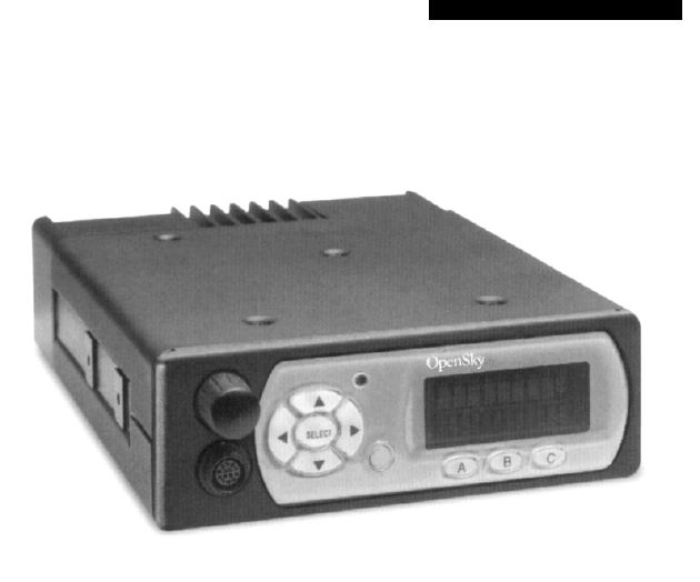
CHAPTER 6—Advanced Radio Operations
66 M-803 Operator Manual Software Version OTP 5.07
Fine-Tuning Your Personality
Access to as many as 16 profiles within your pre-
determined radio personality gives you tremendous
responsiveness to the changing needs of your workday.
What’s more, within each profile, the flexibility of the
IP-protocol OpenSky network makes it possible to
fine-tune your radio’s sensitivity to incoming voice
calls by changing the Scanning Priority of specific user
groups, changing radio scanning modes and channels,
even locking out the incoming voice calls of entire user
groups.
In some ways, these sensitivity tunings are analogous
to operations familiar to users of analog equipment.
Dynamic Regrouping
In the event of an emergency, the network admini-
strator will determine what radio users should be
formed into an ad hoc talk group to respond to the
emergent conditions.
The administrator will edit the personalities of the
affected users to include an emergency profile, then
direct the affected users to re-register with the network
to receive their edited personalities.
• In response, affected users Log-On with their User
ID numbers to receive their edited personalities.
• During Log-on, subscriber equipment will default
to the dynamically regrouped profile.
• In all likelihood, one profile per personality will be
reserved for Dynamic Regrouping use.

Advanced Radio Operations—CHAPTER 6
Software Version OTP 5.07 M-803 Operator Manual 67
Ø How to Re-Provision for an
Emergency
1.) “Punch In” your User ID when directed by the
Network Administrator.
2.) Re-registration will default to Dynamically-
Regrouped Emergency Profile.
Talkaround Mode
In the absence of a nearby Base Station, in deep woods
or valleys, or in other weak coverage areas, it is
possible to work “off-network” by selecting
Talkaround Mode and placing radio-to-radio calls in
conventional FM or Project 25 Digital Common Air
Interface modes.
VTac Vehicular Tactical Network
Also useful for supporting a local tactical operation,
Talkaround is a digital air link protocol that allows
unit-to-unit communication without talk paths to the
base site and switching center.
Ø How to Place Talkaround Calls
1.) Use the Up and Down buttons to cycle through
the Menu choices until Talk Menu appears.
2.) Use the Left and Right buttons to cycle through
the Talkaround Menu options established by your
Network Administrator.
3.) Press the Select button to lock in your choice.
Your selected Dwell Display will appear as soon as the
M-803 accepts your choice.

CHAPTER 6—Advanced Radio Operations
68 M-803 Operator Manual Software Version OTP 5.07
Troubleshooting
If your radio does not operate properly, check the chart
below for likely causes. For additional assistance,
contact a qualified service technician.
Symptom Likely Cause Solution
Radio will not
turn on Dislodged power
connector. Press in the power
connector on the rear of
the radio.
In-line fuse is blown. Replace the in-line fuse.
Your radio may be too hot. Allow the radio to cool or
operate the radio in a
cooler environment.
Report this failure to
authorized technician.
No audio Speaker volume is muted. Increase the volume level.
Speaker cable is not
connected. Press in the speaker cable
on the rear of the radio.
Poor audio You are in a poor coverage
area or not on the network. Move to a better coverage
area using the signal
quality indicator on the
display as a guide, or use
Mode Menu to enable
conventional FM radio
operation.
Speaker cable is loose. Press in the speaker cable
on the rear of the redio.
Antenna connection is
loose. Ensure that the antenna is
properly connected to the
radio.

Advanced Radio Operations—CHAPTER 6
Software Version OTP 5.07 M-803 Operator Manual 69
Symptom Likely Cause Solution
Poor display
visibility Ambient light sensor is
obstructed. Clear obstruction and give
sensor a clear path to
ambient light.
Screen
displays:
No Access
Your radio is out-of-range
or cannot connect with the
OpenSky network.
Move to a better coverage
area using the signal
quality indicator on the
display as a guide, or use
Mode Menu to enable
conventional FM radio
operation.
Radio will not
transmit Your radio may be too hot.
The M-803 will cease
transmitting if it exceeds
an operational temperature
threshold.
Let the radio cool before
attempting to transmit.
Report this failure to
authorized technician.
Your radio may be
experiencing low voltage.
The M-803 will cease to
transmit when voltage
drops below 9 volts.
Reduce the load on your
vehicle’s battery and try
again. Report this failure
to authorized technician.
Radio
unexpectedly
Powers Down
Your radio may be
experiencing very low
voltage. The M-803
automatically powers down
when voltage drops below
4.5 volts.
Reduce the load on your
vehicle’s power supply
and try again. Report this
failure to authorized
technician.
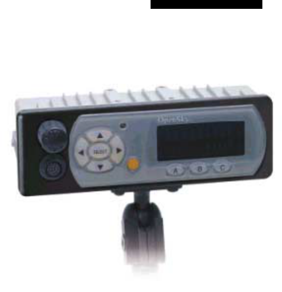
Control Head Unit—CHAPTER 7
Software Version OTP 5.07 M-803 Operator Manual 71
CHAPTER 7
CH-103 Control Head
Features and Components 72
Equipment Configurations 73
Dash-Mount Mobile Configuration 73
Dash-Mount Mobile with CH-103 74
Trunk-Mount Mobile Configuration 76
Vtac Vehicular Tactical Network 77
Full or Shared Radio Controls 78
Single Control Head 79
Multiple Control Heads 79
Independent Functions 79
Shared and Arbitrated Functions 80

CHAPTER 7—Control Head Unit
72 M-803 Operator Manual Software Version OTP 5.07
Features and Components
The OpenSky CH-103 provides remote access for
voice and data, as well as remote user interfaces to
control M-803 mobile radios and VTac Vehicular
Tactical Networks.
OpenSky’s digital interface allows easy connection to
mobile radios, vehicular repeaters, control stations,
mobile data terminals and CAN peripherals to support
the public safety mission.
Local or Broadcast Intercom
The control head can also function as an intercom by
broadcasting received voice calls to all consoles, to
specific installed consoles, or by allowing users to
bypass the network to communicate with each other.
Full Feature Set
Because the OpenSky M-803 is the core component of
any dash- or trunk-mounted configuration, each
Control Head can access the full range of features
supported by the radio it controls.
Front Panel Interface
The front panel of the CH-103 is the front panel of an
M-803 mobile radio, with the same display screen,
menu buttons and controls as described elsewhere in
this manual. See Front Panel Components for more
details.
Rear Panel Peripheral Interface
The CH-103 provides interfaces for analog and digital
peripherals, similar but not identical to those supported
by the M-803 mobile radio. See Peripheral Interface
for more details.
On a large vehicle with
several Control Heads,
each will share access to a
single M-803 mobile radio.
See Multiple Control Head
for more details.

Control Head Unit—CHAPTER 7
Software Version OTP 5.07 M-803 Operator Manual 73
Equipment Configurations
The M-803 mobile radio supports multiple control
heads for vehicles that require more than one display
screen and user interface.
Dash Mount Mobile
In the most basic configuration, the M-803 radio and
user interface are combined in one dash-mounted
hardware case without additional control heads.
Dash Mount with Control Heads
The dash-mount radio can support up to five control
heads at different locations on the vehicle, each with its
own display screen and interfaces for handsets, mobile
data terminals and other peripherals.
Trunk Mount Mobile
The M-803 can also be remotely trunk-mounted
without a front-panel user interface. This configuration
supports up to five control heads placed throughout the
vehicle.
Vehicular Tactical Network
With the addition of a trunk-mounted duplexer and
signal repeater, the M-803 functions as a local cell on
the OpenSky network and also provides off-network
scene-of-incident coverage for voice-to-voice
communication.
Dash-Mount Mobile Configuration
The first several chapters of this manual describe the
basic dash-mount mobile configuration for the M-803.
In this common standalone installation radio functions,
front-panel user controls and back-panel peripheral
interfaces are combined in a single hardware case.
Figure 23 Dash-Mount Mobile
Sample Installation
The CH-103 Control Head
unit brings the
convenience of the user
interface and optional
peripherals to several
locations in a vehicle
without the expense of
mounting several radios.
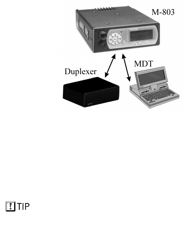
CHAPTER 7—Control Head Unit
74 M-803 Operator Manual Software Version OTP 5.07
Component Explanation
Duplexer.................... M-803 supports optional duplexer
for Full Duplex operation.
MDT .......................... M-803 supports optional Mobile
Data Terminal for full-feature
graphics.
Dash-Mount Mobile with CH-103
The dash-mounted M-803 described above can be
expanded for larger or special needs vehicles with the
addition of up to five optional Control Heads
(CH-103).
As in the standalone installation, the dash-mounted
mobile supports an optional duplexer for full duplex
operation and a mobile data terminal for full-feature
graphics. Voice operations to and from the multiple
control heads share a single mobile radio RF channel.
In addition, each Control Head provides the following
components and capabilities:
• Remote Shared Voice access to the M-803,
• Remote Control for the M-803,
The control heads provide
shared voice access to the
M-803, not additional radio
personalities or channels.
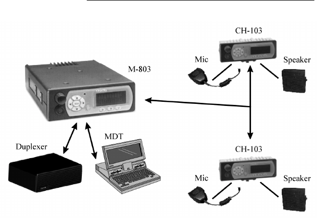
Control Head Unit—CHAPTER 7
Software Version OTP 5.07 M-803 Operator Manual 75
• Complete common User Interface including
display screen, preset buttons, and menu/selector
keypad,
• Individual Audio controls,
• I/O port for wired Microphone/Speaker,
• Alternate interface site for Mobile Data Terminal
(limit one MDT per installation).
Figure 24 Dash-Mount with Control Heads
Sample Installation
Component Explanation
Duplexer ................... M-803 supports optional duplexer
for Full Duplex operation.
MDT.......................... M-803 supports optional Mobile
Data Terminal for full-feature
graphics.
CH-103...................... Each Control Head supports
mic/speaker and an alternate site
for MDT installation.
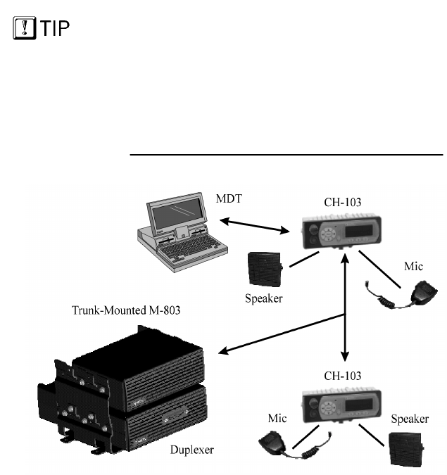
CHAPTER 7—Control Head Unit
76 M-803 Operator Manual Software Version OTP 5.07
Trunk-Mount Mobile Configuration
For trunk-mount installation, the M-803 is installed
without a front panel user interface. Instead, one or as
many as five Control Head units throughout the vehicle
provide remote control for radio functions.
The M-803 supports an optional duplexer for full
duplex operation.Voice operations to and from multiple
control heads share a single mobile radio RF channel.
Figure 25 Trunk-Mount Mobile
Sample Installation
Component Explanation
Duplexer.................... M-803 supports optional duplexer
for Full Duplex operation.
MDT .......................... Each CH-103 provides interface
for optional Mobile Data
Terminal (MDT).
CH-103 ...................... Each Control Head supports a
microphone and speaker.
The control heads provide
shared voice access to the
M-803, not additional radio
personalities or
frequencies.

Control Head Unit—CHAPTER 7
Software Version OTP 5.07 M-803 Operator Manual 77
In addition, each Control Head provides the following
components and capabilities:
• Remote Shared Voice access to the M-803,
• Remote Control for the M-803,
• Complete common User Interface including
display screen, preset buttons, and menu/selector
keypad,
• Individual Audio controls,
• I/O port for wired Microphone/Speaker,
• Alternate interface site for Mobile Data Terminal
(limit one MDT per installation).
VTac Vehicular Tactical Network
The Vehicular Tactical Network is described in detail
in the following chapter.
For a trunk-mounted VTac installation, the M-803 is
installed without a user interface. Instead, as many as
five Control Head units at locations throughout the
vehicle provide remote control for all radio functions.
VTac includes a duplexer for Full Duplex operation
and a voice repeater to provide off-network scene-of-
incident coverage.
In short, the VTac supports a rich array of radio
communications features, including:
• All M-803 voice and data radio functions,
• Network Extension support for portables in weak
coverage areas or in-building use,
• Scene of Incident support for voice-to-voice off-
network communications,
• Full Duplex operation,
• Up to five control heads and one mobile data
terminals.
The OpenSky M-803 is the
core component of the
Vehicular Tactical Network.
Your VTac radio will
perform all the best
functions of the M-803
plus additional coverage
enhancements.
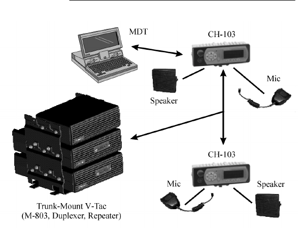
CHAPTER 7—Control Head Unit
78 M-803 Operator Manual Software Version OTP 5.07
Figure 26 VTac Vehicular Tactical Network
Sample Installation
Component Explanation
VTac .......................... Three hardware components
mounted together make up the
VTac array.
MDT .......................... Each CH-103 provides interface
for optional Mobile Data
Terminal (MDT).
CH-103 ...................... Each Control Head supports a
microphone and speaker.
Full or Shared Radio Controls
The Control Head unit provides remote voice, data, and
control paths to the M-803 for one or as many as five
control heads per installation.
In an installation with a Single Control Head, the sole
CH-103 has full control of the mobile radio as well as
the front panel interface and local speaker.
Control Head Unit—CHAPTER 7
Software Version OTP 5.07 M-803 Operator Manual 79
In an installation with Multiple Control Heads,
communications functions are generally shared among
all control heads, while local interface functions like
volume and brightness are independently controlled for
each CH-103.
Single Control Head
In Single Control Head mode, the CH-103 is the sole
user interface for the trunk-mounted mobile and the
full features of the front panel and local speaker.
Features operated by the Control Head unit in Single
Control mode include:
• Speaker volume
• Screen brightness
• Mode selection
• Voice group selection
• Emergency mode
Since the radio is controlled by a single control head,
there is no need for the mobile radio unit to arbitrate
control of radio functions.
Multiple Control Heads
The Multiple Control Head configuration organizes
operational functions into an Independent group and a
Shared group.
Independent Functions
Each Control Head in a multi-head installation can be
adjusted for local conditions without affecting the
settings on the other control heads.
Independent control head functions include:
• Speaker volume
• Screen brightness
• Side tones on or off

CHAPTER 7—Control Head Unit
80 M-803 Operator Manual Software Version OTP 5.07
Shared and Arbitrated Functions
Examples of shared functions which will affect the
operational status of all connected control heads:
• Power Up and Log-On
• Mode selection
• Voice group selection
• Emergency mode
For shared functions, the action of one user affects the
operation of shared mobile radio unit functions. If one
user changes from Trunked mode to Scene of Incident
mode, for example, all control heads will update to the
same mode.
The general rule for
shared functions is:
any control head can
change shared
functions for all control
heads.
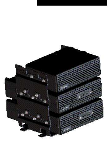
Software Version OTP 5.07 M-803 Operator Manual 81
8181
81
CHAPTER 8
VTac Vehicular Tactical Network
Vehicular Tactical Network 82
Backward and Forward Compatibility 82
Operational Modes 83
“A Base Station in a Trunk” 83
Hardware Components 84
VTac Mobile Unit 84
VTac Base Unit 85
RF Combiner 85
Extended Coverage 85
User Interaction 85
Scene of Incident 86
User Interaction 86
Public Safety Hardened 86
GPS Option 87
Connectivity Interface 87
CHAPTER 8—VTac Vehicular Tactical Network
82 M-803 Operator Manual Software Version OTP 5.07
Vehicular Tactical Network
The Vehicular Tactical Network (VTac-803) is an 800
MHz software-based digital mobile network repeater
for extending network coverage to portable radios,
providing scene-of-incident capability and the full
feature set of an M-803 mobile radio.
VTac supports the OpenSky communication protocol
in the 800 MHz SMR and NPSPAC frequency bands
with a high performance data modem that gateways
both voice and data to the OpenSky wide area wireless
data network.
More capable than a stand-alone M-803, the VTac-803
is a hybrid product that combines several hardware
components into a multi-use communications device to
extend the capabilities of a movable Base Station
wherever you position your vehicle.
Backward and Forward Compatibility
The software-based architecture allows the VTac-803
to be programmed for a variety of modulation
techniques, providing legacy support and guarding
against obsolescence.
VTac can host several applications simultaneously to
support users running the OpenSky digital protocol,
Conventional FM with CTCSS, or Project 25 Phase 1.
Over-the-Air Programmability
For agencies engaged in an analog-to-digital transition,
The VTac-803 can function with existing analog
infrastructure today and, when the time is right, receive
over-the-air field reprogramming for a virtually
seamless transition to fully digital communications
without replacing equipment.
VTac Vehicular Tactical Network —CHAPTER 8
Software Version OTP 5.07 M-803 Operator Manual 83
Operational Modes
By combining the functions of several components, the
VTac-803 operates in a variety of modes:
• Mobile Radio. This is the default mode of
operation activated at Power-Up. Under ordinary
conditions, the VTac-803 is a fully-functioning
subscriber device performing all the functions of
an M-803 radio on the OpenSky network;
• Extended Coverage. In weak coverage areas, the
VTac Base Station can be activated to act as a
mobile base station, extending OpenSky network
connectivity to portable radios in the vicinity. The
VTac continues to provide normal mobile radio
functions in Extended Coverage mode;
• Scene-of-Incident. For radios on the OpenSky
network, VTac acts as a voice repeater in OpenSky
Trunked mode, supporting two concurrent voice
calls between subscribers at the scene;
• Mutual Aid. For radios not on the OpenSky
network, VTac can still provide a limited set of
communication capabilities, acting in Scene-of-
Incident mode as a public safety “micro-cell” to
connect users in a conventional FM Mutual Aid
network.
“A Base Station in a Trunk”
Most commonly, VTac is a trunk-mounted installation
of components that adds the most important functions
of a single-channel OpenSky Base Station to the radio
functions of an M-803 Mobile.
The VTac-803 is designed specifically with the Public
Safety user in mind. Its digital interface easily connects
to peripheral devices including the Control Head and
CAN Peripherals that are often used to support the
Public Safety mission.
CHAPTER 8—VTac Vehicular Tactical Network
84 M-803 Operator Manual Software Version OTP 5.07
Hardware Components
The VTac-803 is a 4-piece array of hardware
components consisting of:
• An M-803 Full Duplex Trunk Mounted Mobile
Radio Unit (MRU), also known in this
configuration as the VTac Mobile;
• A VTac Base Unit. This component brings the
communications interface and transceiver
functionalities of an OpenSky Base Station DCX
to the trunk of a patrol car;
• An RF combiner;
• A CH-103 Control Head located in the passenger
compartment of the vehicle controls the three
trunk-mounted components.
Additional Control Head units may be located
elsewhere in larger vehicles for user convenience.
VTac Mobile Unit
The VTac Mobile provides the connection between the
OpenSky network, operator, mobile data terminal, and
the VTac Base Unit.
As a mobile radio, it operates like a standard-
installation M-803, providing network communications
for a single vehicle through one or more CH-103
Control Head Units.
In a VTac installation, the VTac Mobile is connected to
the VTac Base Unit by a serial cable that conducts
voice and data between the two components.
One-Button Activation
Powering Up the VTac Mobile automatically enables
all the connected hardware components of the VTac
array. Unless they’re needed, though, the RF Combiner
and VTac Base Unit stand by in a quiescent state until
called on for use.
VTac Vehicular Tactical Network —CHAPTER 8
Software Version OTP 5.07 M-803 Operator Manual 85
VTac Base Unit
The VTac Base Unit has the same transceiver and
digital controller components as the OpenSky Base
Station DCX, but in a VTac installation these
components only operate as needed, when enabled by
the subscriber.
When Extended Coverage is required, the VTac Base
Unit provides the extended connection between the
network and portable radios in the vicinity.
When Scene-of-Incident coverage is required, the
VTac Base Unit provides communication between
subscriber devices at the scene.
RF Combiner
The RF Combiner provides the VTac Network with the
ability to create an ad hoc talk group for Scene-of-
Incident emergency communications.
Extended Coverage
The VTac-803 can be used as a mobile base station to
ensure that portable radios are connected to the
network at all times, in-building, or out.
Subscribers with VTac equipment can enable Extended
Coverage mode before leaving their vehicles to enter
buildings or spotty coverage areas, thereby assuring
signal strength to networked portables.
User Interaction
Extended Coverage requires subscriber activation.
Without interaction the subscriber’s mobile and
portable radios are served by the nearest network cell.
By selecting Extended Coverage mode, the subscriber
activates the VTac Base Unit as a local cell on the
OpenSky network.
CHAPTER 8—VTac Vehicular Tactical Network
86 M-803 Operator Manual Software Version OTP 5.07
Scene of Incident
The VTac-803 can also be a vital link at the scene of an
incident, providing a repeater among OpenSky sub-
scriber radios, or alternatively, among radios in a
Mutual Aid network that connects different radio types,
whether they subscribe to OpenSky or not.
In Scene-of-Incident (SOI) Mode, OpenSky Network
communications are sacrificed to enable full emer-
gency connectivity between cooperating agencies at the
scene. The tradeoff of network isolation provides
increased channel capacity while relieving traffic for
other subscribers on the network.
In Scene of Incident mode with OpenSky Trunking,
VTac supports multiple talk groups. Like a tower site
base station, it continues to support agency-specific
talk groups while at the same time creating an ad hoc
talkgroup for units at the scene.
User Interaction
Scene-of-Incident coverage is not automatic. The
VTac-equipped subscriber will make an on-scene
command decision to manually activate SOI mode and
become the local cell for all calls on an ad hoc
network.
In addition, all portable radio users must select SOI
mode and tune to the VTac frequency to join the
emergency network.
Public Safety Hardened
The VTac-803 is designed specifically with the Public
Safety user in mind.
The case is manufactured with enhanced environmental
hardening making the VTac compliant with
MIL-STD-810 for temperature, altitude, solar
radiation, rain, humidity, salt, fog, sand, dust, vibration,
and shock, ensuring that it will perform under the wide
range of public safety environmental conditions.
VTac Vehicular Tactical Network —CHAPTER 8
Software Version OTP 5.07 M-803 Operator Manual 87
GPS Option
The OpenSky VTac-803 can be supplied with an
optional embedded GPS receiver. GPS data can be
reported either over-the-air to remote dispatch
positions or to a local terminal connected directly to the
mobile radio.
Additionally the I/O connector provides a serial GPS
port which outputs GPS NEMA messages. Reporting
characteristics can be configured remotely and can be
event driven.
GPS functions are transparent to the subscriber and
require no user interaction.
Connectivity Interface
The VR-803 supports a variety of interfaces with its
flexible interconnect. The M-803 and VRB connect to
the RF Combiner via the antenna ports located on the
rear panel.
Peripheral Support
The rear panel also provides interfaces for both analog
and digital peripherals.
The serial RS-232 port operates in asynchronous
ASCII mode for configuration and control and switches
to Serial Line Internet Protocol (SLIP) mode for data
communication between the fixed network and a
mobile computer or terminal device.
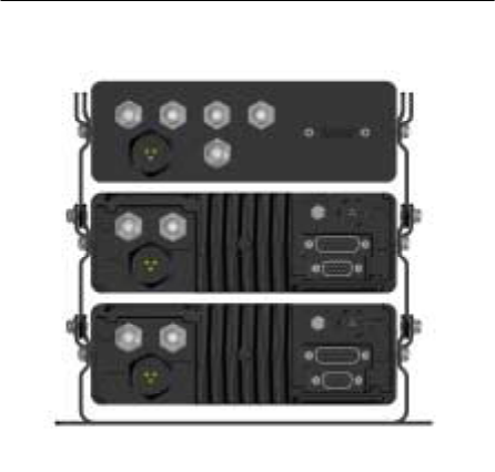
CHAPTER 8—VTac Vehicular Tactical Network
88 M-803 Operator Manual Software Version OTP 5.07
Figure 27 VTac Connectors
Rear Panel Schematic
I/O Connector
The I/O connector provides interfaces for an external
10 Watt speaker and duplexer support. Additionally,
the I/O connector provides access to a GPS serial port
which outputs NEMA messages.
Power Supply
The power supply interface is designed to power the
VR-803 from the vehicle car battery.
CAN Peripheral Bus
The rear panel also provides access to an industry
standard 1 Mbit Controller Area Network (CAN) 2.0B
bus for reconfigurability and peripheral support.
This allows the VR-803 to be controlled by up to five
Control Head (CH-103) units and connect with public
address and other CAN peripherals.
VTac Vehicular Tactical Network —CHAPTER 8
Software Version OTP 5.07 M-803 Operator Manual 89
The CAN bus enables modularity and upgradeable for
new applications. The maximum length of the CAN
bus is 40 meters.

Software Version OTP 5.07 M-803 Operator Manual I-ii
Indexes and Tables
Index
(OTP) OpenSky Trunked
Protocol, 9, 22, 37
25kHz RF channel, 7
active profile, 34, 39, 40, 41, 42,
45
Active Profile, 34, 39, 41, 42, 45
active scan mode
check or change, 49
ad hoc work group, 17
addressability, 2
ambient light sensor, 21, 22
analog equipment, 2, 4, 5, 6, 8, 9,
10, 12, 18, 20, 23, 37, 39, 66
analog radios, 2, 8
analog voice waves, 4
analog, compare to digital, 18
APCO Project 25 Common Air
Interface, 8, 9, 22, 37
APCO Project 25 Phase 1, 8, 9,
22, 37
ASCII, 23
asynchronous ASCII, 23
audible side tones, 34, 52
base station, 3, 6, 7
BIST
Error Code, 59
block out non-emergency voice
calls, 44
Booting message
mode change, 38
brightness
select setting, 53
Brightness Menu, 53, 54
brightness selection, 53, 54
brightness setting, 34, 53
Built-in Self-Test, 58, 59
busy signal, 62
Index and Tables
iv M-803 Operator Manual Software Version OTP 5.07
call in queue, 62
Caller, current, 27, 35
CAN peripheral, 23
CAN port, 23
CH-103 Control Head Unit, 23,
24
channel
change, 51
select, 51
Channel Menu, 34, 51, 75, 76, 77,
79
communication protocols, 6, 9,
25, 37
connectivity, universal, 37
Control Area Network, 23, 24
Control Area Network (CAN) 2.0
Bus, 23, 24
Control Head Unit (CHU), 20
conventional FM, 2, 3, 7, 12, 13,
14, 16, 37, 67, 68
conventional radio mode, 31
coverage area, 4, 6, 7, 38, 67, 68
coverage mode, 38
Coverage Mode, 5, 6, 34, 38
CTCSS analog FM, 8, 37
Current Profile, 14
dash-mounted, 3, 21
diagnostic self-test (BIST), 58, 59
digital trunking, 7, 9
digital voice and data, 2, 3, 7, 37
digital, compare to analog, 18
display screen, 8, 16, 25, 26, 34,
35, 36, 43, 45, 46, 54, 61
Display Screen functions, 28, 33,
34
duplexer, 6
Dwell Display, 14, 25, 27, 28, 29,
30, 34, 35, 36, 40, 41, 42, 43,
46, 47, 49, 50, 51, 53, 54, 56,
58, 59, 60, 61, 67
Dwell Display hierarchy, 28
Dwell Display Menu, 25, 27, 30,
35
Dwell Display, Caller, 29
Dwell Display, Channel, 30
Dwell Display, Profile, 28
Dwell Display, Received
Talkgroup, 29
dynamic regrouping, 22, 37, 66
dynamic voice group assignment,
7
emergency
calls and alerts, 63
send alert in an, 63
emergency alert, 22, 64
emergency button, 21, 64
emergency calls, 7, 10
pre-emptive, 10
emergency communications, 63
emergency profile, 67
emergency talkgroup, 64
enable/disable side tones, 52
encrypted, 3
encryption, 7
optional, 7
end of message tone, 62
end-to-end digital voice and data,
3
Error Code, 59
field programmable, 9
FM
conventional, 8, 9, 18, 22
FM, conventional, 2, 3, 7, 8, 9,
12, 13, 14, 16, 18, 22, 37, 67,
68
Full Duplex, 24
GPS NEMA, 24
GPS tracking device, 8
hands-free speaker, 21, 22
hardware connections, 23
I/O connector, 23
identity code, 8, 12, 16
incoming voice calls, responding
to, 41, 66
integrated voice and data, 2, 3
IP address, 3, 12, 16
Index and Tables
Software Version OTP 5.07 M-803 Operator Manual v
IP backbone, 37
IP protocol, 3, 4
IP-backbone digital network, 13,
14
key-entry device, 4
keypad navigation, 34
laptop PC, 4
legacy equipment, 2, 6, 18
light sensor, 21, 22
Listen Group, 12, 14, 15, 16, 17,
39, 40, 41, 44, 48, 49, 50, 61,
63
listen-only, 14, 15
lock out
duration of lockouts, 48
limitations, 45
locked-out groups, 48
unlock, 46
lock out talkgroup, 44
Lock Out Talkgroup, 17, 44, 45,
46, 47, 48
Lockout Menu
received calls, 45
Log-on, 9
Log-On, 57, 58, 66
Menu and Selector Keypad, 34
Menu Display, 25
menu headings, 35
menu operations
keypad-accessible, 34
user-selectable, 34
menu option, 36, 39, 41, 42, 44,
47, 50, 52, 53, 54
menu selection, 25, 26, 27
Menu/Select procedure, 26
message receive, 26
message send, 26
Mic/Speaker, 22
mobile computer, 4, 21, 23
Mobile Data Terminal, 4, 6
Mobile Data Terminal (MDT), 4
Mobile Radio Unit, 20, 58
mode
operational, 34, 36
mode change, duration of, 38
Mode Menu, 31, 38, 39, 49, 50,
68
Mode Selection Menu, 9, 37
Mode Selector, 21, 22
mode, operational, 34, 36
multi-agency, 5, 37
multi-mode functionality, 8
network administrator, 12, 13, 14,
15, 16, 18, 28, 39, 49, 63, 66
network organization, 11, 20
No Access, 30, 31, 68
No Scan, 34, 44, 48, 49, 50
select mode, 48
No Scan Mode, 34, 44, 48, 49, 50
non-emergency voice, 44
nonfatal failure
BIST, 59
nonfatal failure (BIST), 59
Normal Mode, 34, 50
Normal Scan
select mode, 34, 49, 50
off-network modes, 5, 7, 31, 38,
57, 67
OpenSky Conventional FM, 9, 37
OpenSky network, 2, 3, 10, 14,
30, 37, 57, 61, 66, 68
OpenSky protocols, 25
OpenSky Trunked Mode, 9, 34,
37
OpenSky Trunked Protocol, 9, 37
operational mode, 34, 36
OTP
OpenSky Trunked Protocol, 9,
37
over-the-air download, 37
Over-the-Air Download Mode,
34, 37
peripheral interface, 6, 20, 21
personality, 12, 16, 17, 20, 39,
40, 43, 48, 56, 57, 58, 60, 66.
See Radio Personality
Index and Tables
vi M-803 Operator Manual Software Version OTP 5.07
dynamically regrouped, 67
fine-tuning your radio, 66
personality upgrade, 37
Power Button/Speaker Volume
Dial, 21
Power Button/Volume Dial, 56,
57, 58, 59, 60, 61, 62
Power Down, 22, 28, 38, 50, 56,
59, 60, 69
Power Off, 44
Power Up, 22, 39, 56, 57, 58, 59,
60, 62
Pre-emptive emergency calls, 10
preset channel menu, 34
priorities
multi-level, 7
prioritizing a talkgroup, 43
priority assignments
duration of, 44
priority scan group, 17, 43
Priority Scan group, 17
priority scanning, 10
Priority Talkgroup, 34, 43, 44,
45, 48
profile
active, 34, 39, 40, 41, 42, 45
change active, 40
change or check active, 40
check active, 40
dynamically-regrouped, 67
select a, 39
set active, 40
Profile
current, 25, 27, 35
Profile Menu, 14, 40, 41, 42
Profile, current, 25, 27, 35
protocol, 6, 9, 25, 37
protocols, 6, 9, 25, 37
provisioning, 12, 16, 39, 56, 57,
58
radio personality, 56, 57, 58
regrouping in emergency, 67
Push-to-Talk button, 16, 21, 62,
63, 64
push-to-talk contact, 13, 14, 15
radio controls, 20
radio personality, 12, 16, 39, 40,
43, 48, 56, 57, 58, 66
provisioning, 12, 16, 39, 56,
57, 58
Radio Personality, 16, 17
Received Talkgroup, 25, 27, 28,
29, 30, 36, 61
regrouping, dynamic, 37, 66
RF channel, 7
RF data, 25
roaming and switching,
background, 7
rollover
analog-to-digital, 9
RS-232 interface, 4
scan mode
change active, 49
change or check active, 49
check active, 49
duration of selections, 50
selecting a, 48
Scan Mode Menu, 49, 50
scanning
priority, 10
Scanning Mode, 34, 44, 50
screen display
default preference, 27, 35
select brightness setting, 53
Select button, 22, 35, 36, 38, 39,
40, 41, 42, 43, 44, 46, 47, 48,
50, 51, 52, 53, 54, 67
select channel, 51
select profile, 39
select scan mode, 48
select talkgroup, 41
Selection Display, 25
Selector buttons, 22, 40
Self-Test (BIST), 58, 59
Serial Line Internet Protocol, 23
Index and Tables
Software Version OTP 5.07 M-803 Operator Manual vii
set volume, 60
Side Tone Menu, 52
side tones, 34, 52, 53
enable/disable, 52
signal reach, 7
signal repeater, 6, 7
signal strength, 7
Signal Strength icon, 25
signal strength indicator, 62
sign-on, 9
SLIP, 23
software applications, 8
software upgradeable, 9
software-configured, 8
speaker
hands-free, 21, 22
speaker box, 21
speaker volume, 21, 25, 57, 58,
60, 61
Speaker Volume Dial/Power
Button, 21
Speaker Volume icon, 25
startup sequence, 56, 57
SWAT team, 14
switching station, 7
Talk Group, 3, 6, 10, 12, 13, 14,
15, 16, 17, 39, 48, 49, 63, 64,
66
talkaround mode, 57, 67, 68
talkback calls, 63
Talkback Mode, 15, 16, 34, 41,
49, 50, 63
Talkback Scan, 16, 41, 63
select mode, 15, 16, 34, 41,
49, 50, 63
Talkback Scan Mode, 41
Talkback Scanning, 16, 63
talkback scanning mode, 63
talkback timer, 49, 63
talkgroup
change active, 41
change or check, 41
check active, 41
select a, 41
set active, 41
Talkgroup
lockout, 44
prioritizing, 43
Talkgroup Lockout, 34
Talkgroup Menu, 26, 42, 44
talkgroup, ad hoc in emergencies,
66
TCP / IP, 2
TCP / IP Backbone, 2
TDMA technology, 7
transmit talkgroup, 25, 27, 28, 29,
30, 35, 36, 41
Transmit Talkgroup, 25, 27, 28,
29, 30, 35, 36, 41
troubleshooting, 68
trunked mode, 27, 35
Trunked Protocol
OTP, 9, 37
trunking, 7, 9
trunk-mounted, 3, 5, 6, 23
UDP/IP protocol, 4
unit-to-unit communications, 7,
67
unlock listen group, 46
User Group, 12, 13, 16
User ID, 10, 28, 29, 56, 57, 58,
59, 61, 62, 66, 67
User Profile, 2, 5, 8, 12, 14, 15,
17, 20, 22, 26, 27, 28, 29, 30,
34, 35, 36, 39, 40, 41, 43, 44,
45, 46, 47, 48, 49, 58, 61, 63,
66
user protocol, 6, 9, 25, 37
vacuum fluorescent, 21, 25, 56,
57, 60
VFD text, 25
voice calls, 61, 63
voice group assignment
dynamic, 7
voice groups
multiple, 7
Index and Tables
viii M-803 Operator Manual Software Version OTP 5.07
voice-to-voice communications,
7, 15
volume, 21, 25, 57, 58, 60, 61
set volume, 60
Volume Dial/Power Button, 56,
57, 58, 59, 60, 61, 62
volume icon, 25, 26
volume indicator, 25
VTac Vehicular Tactical
Network, 5, 6, 67, 83
World Wide Web, 3
Index and Tables
Software Version OTP 5.07 M-803 Operator Manual iii
Table of Figures
Figure 1 User Group ................................................................................... 13
Figure 2 User Profile................................................................................... 15
Figure 3 Radio Personality.......................................................................... 17
Figure 4 Front Panel Components...............................................................21
Figure 5 Rear Panel Components................................................................ 24
Figure 6 Display Panel Elements................................................................ 26
Figure 7 Dwell Display Hierarchy.............................................................. 28
Figure 8 Dwell Display—Profile ................................................................ 29
Figure 9 Dwell Display—Caller .................................................................29
Figure 10 Dwell Display—Received Talkgroup......................................... 30
Figure 11 Dwell Display—Channel............................................................ 30
Figure 12 Display Screen—No Access....................................................... 31
Figure 13 Dwell Display Selection .............................................................36
Figure 14 Operational Mode Menu............................................................. 39
Figure 15 Profile Selection Menu ............................................................... 41
Figure 16 Talkgroup Selection Menu..........................................................42
Figure 17 Priority Talkgroup Menu............................................................ 44
Figure 18 Lock Out Menu........................................................................... 47
Figure 19 Scan Mode Menu........................................................................ 50
Figure 20 Channel Change Menu ............................................................... 51
Figure 21 Side Tones Menu........................................................................ 53
Figure 22 Brightness Selection Menu......................................................... 54
Figure 23 Dash-Mount Mobile.................................................................... 73
Figure 24 Dash-Mount with Control Heads................................................ 75
Figure 25 Trunk-Mount Mobile.................................................................. 76
Figure 26 VTac Vehicular Tactical Network.............................................. 78
Figure 27 VTac Connectors........................................................................ 88