HARRIS M803M OpenSky M-803 Mobile Radio Systems User Manual Operators Manual
Harris Corporation OpenSky M-803 Mobile Radio Systems Operators Manual
HARRIS >
Contents
- 1. Dash Mount Installation Guide
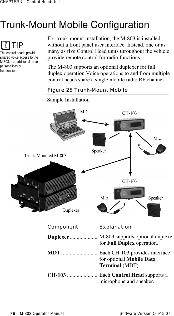
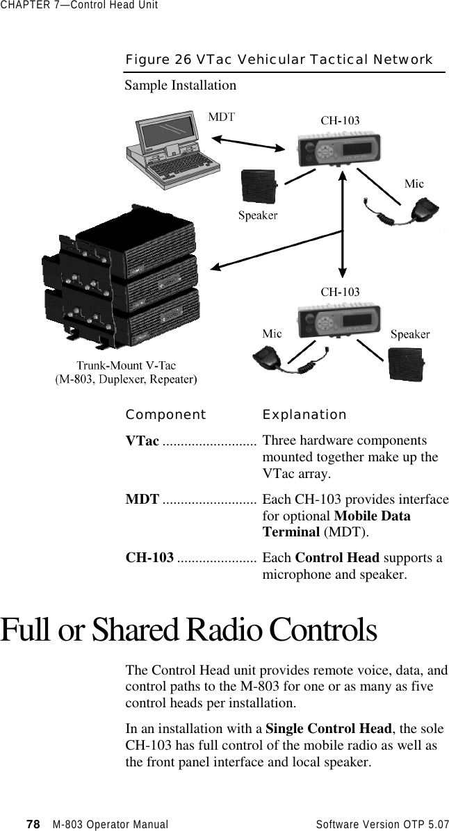
- 2. Trunk Mount Installation Guide
- 3. Operators Manual
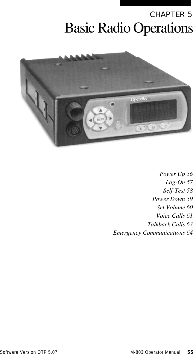
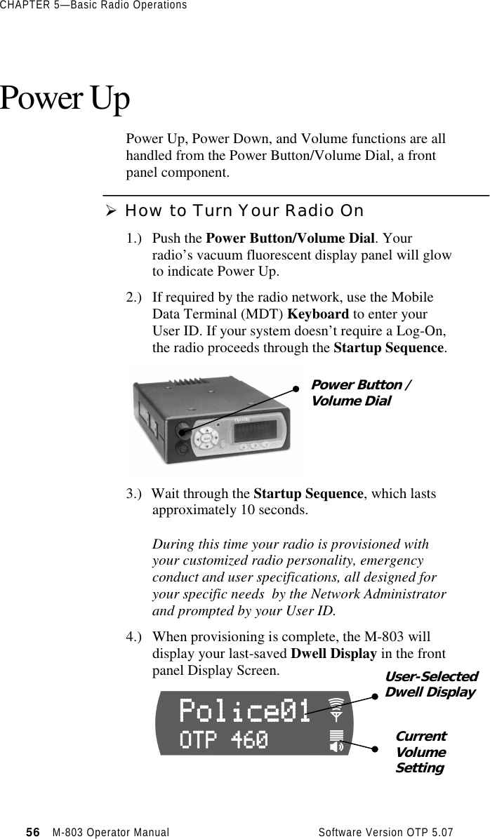
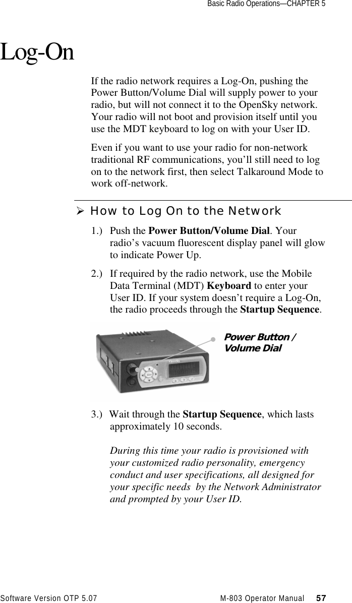
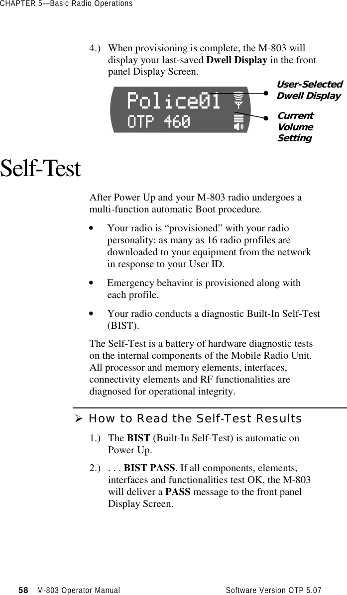
Operators Manual