HARRIS TR-0011-A Panther 300M VHF (136-155 MHz) User Manual TYPE CERTIFICATION REPORT
HARRIS CORPORATION Panther 300M VHF (136-155 MHz) TYPE CERTIFICATION REPORT
HARRIS >
Contents
- 1. Operational manual
- 2. INstallation manual
- 3. Operation Manual
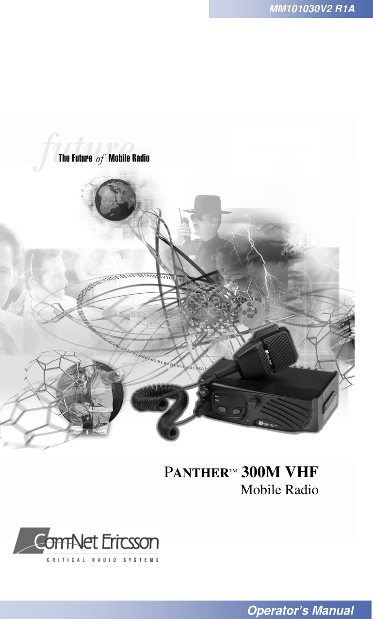
Operational manual
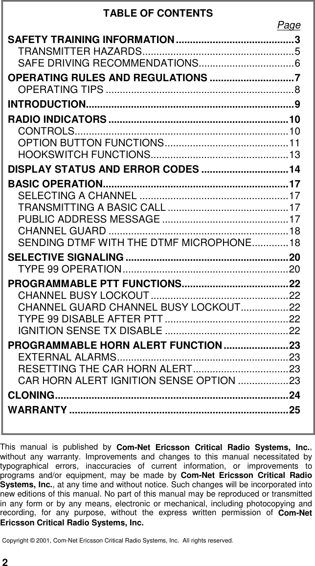
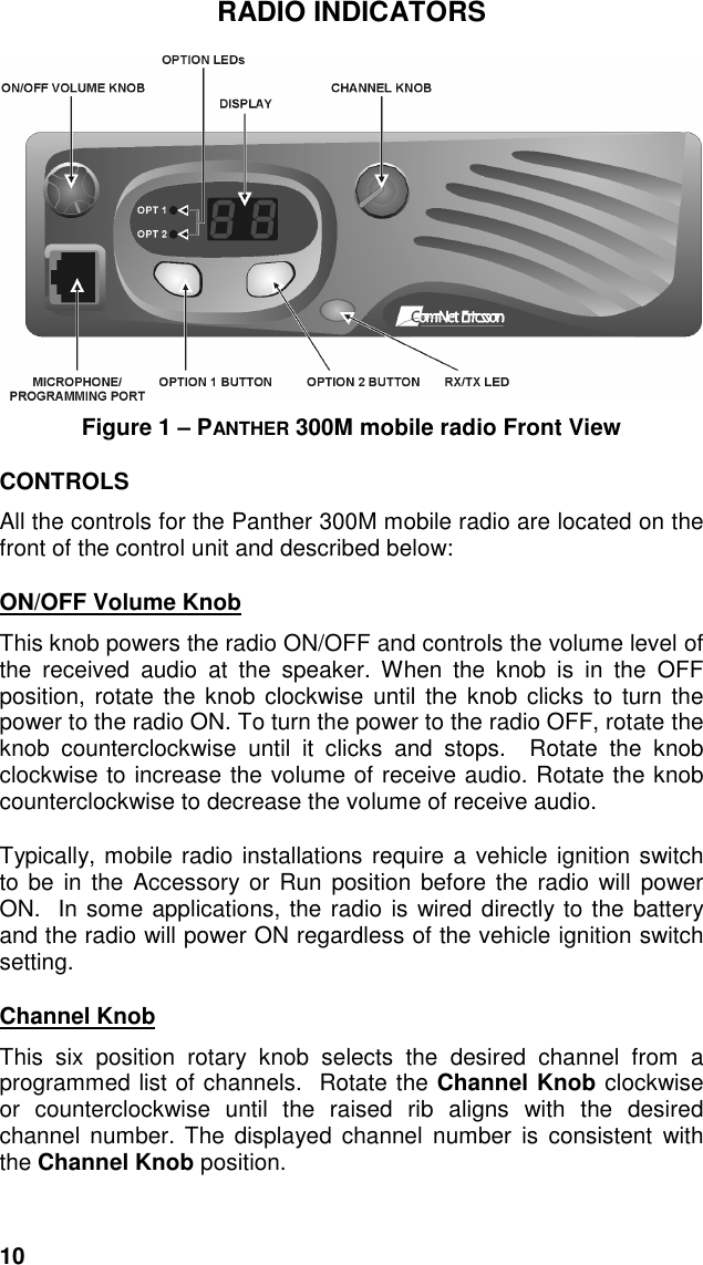
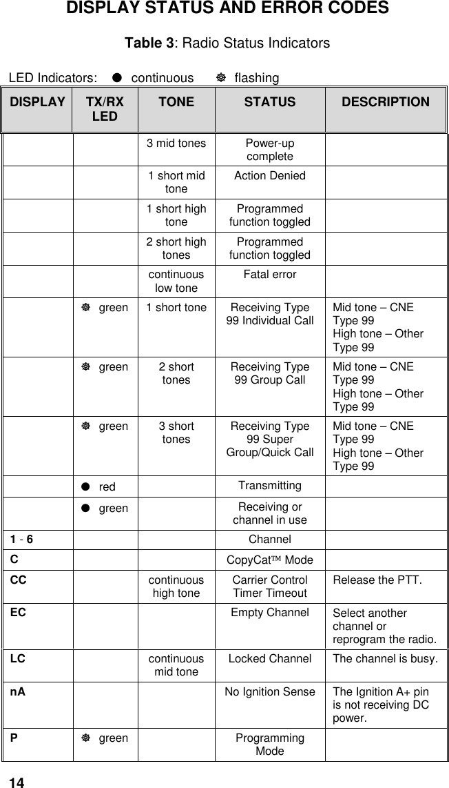
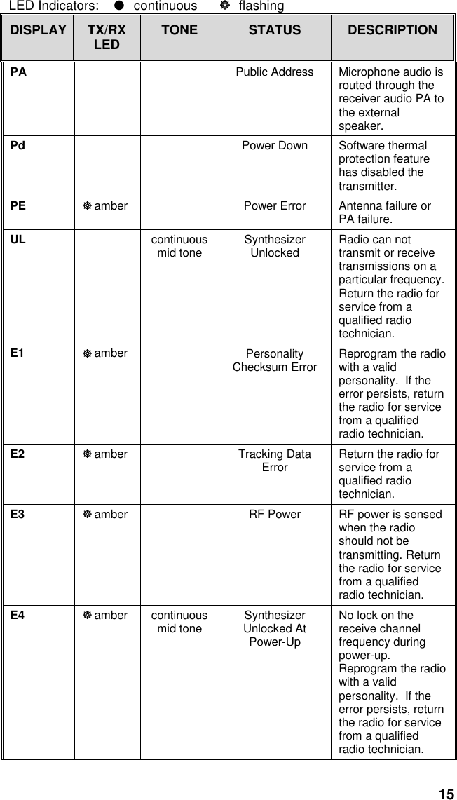
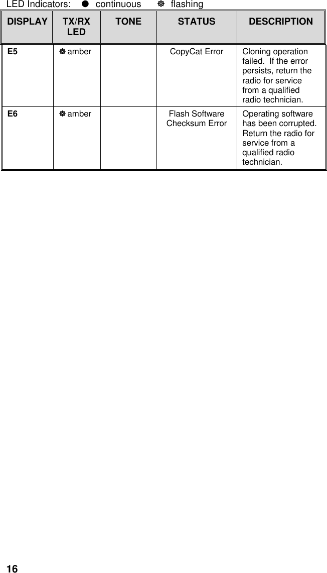
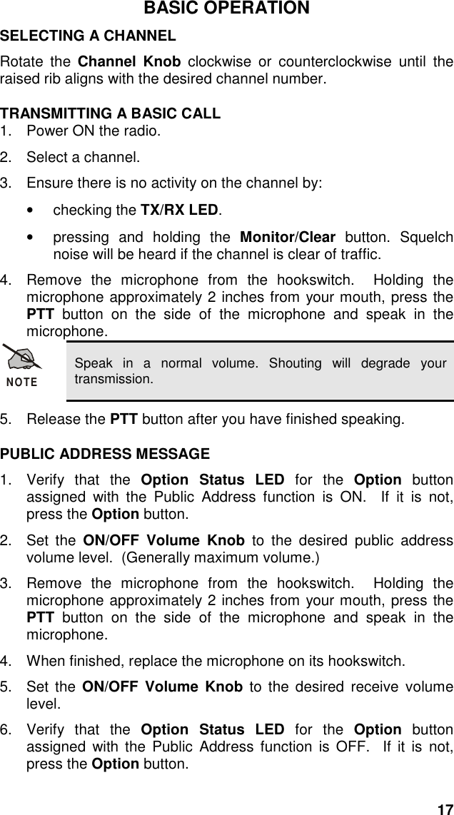
![9INTRODUCTIONThis manual describes the operation for the Com-Net EricssonPANTHER 300M mobile radio. The PANTHER 300M mobile radio is ahigh performance FM mobile radio providing reliable two-waycommunication in a Conventional radio system.The PANTHER 300M mobile radio can be programmed with sixchannels. The PANTHER 300M mobile radio includes a 7-segment,two character, numeric display for channel display.The PANTHER 300M mobile radio operates on any of the followingConventional platforms:• Channel Guard Encode/Decode[Squelch Tail Elimination (STE) optional]• Digital Channel Guard Encode/Decode• Type 99 Decode](https://usermanual.wiki/HARRIS/TR-0011-A.Operational-manual/User-Guide-147469-Page-10.png)