HARRIS TR-0011-A Panther 300M VHF (136-155 MHz) User Manual TYPE CERTIFICATION REPORT
HARRIS CORPORATION Panther 300M VHF (136-155 MHz) TYPE CERTIFICATION REPORT
HARRIS >
Contents
- 1. Operational manual
- 2. INstallation manual
- 3. Operation Manual
Operational manual

360 Herndon Parkway
Suite 1400
Herndon, VA 20170
http://www.rheintech.com
Com-Net Ericsson Critical Radio Systems, Inc. Model: Panther 300M VHF (136-155 MHz)
FCC ID: OWDTR-00011-A 2001056 REV 1 / QRTL01-030 Page 41
FCC and Canadian Certification Report
APPENDIX D: OPERATION MANUAL
MM101030V2 R1A
PANTHER™ 300M VHF
Mobile Radio
Operator’s Manual

2
TABLE OF CONTENTS Page
SAFETY TRAINING INFORMATION..........................................3
TRANSMITTER HAZARDS......................................................5
SAFE DRIVING RECOMMENDATIONS..................................6
OPERATING RULES AND REGULATIONS ..............................7
OPERATING TIPS ...................................................................8
INTRODUCTION..........................................................................9
RADIO INDICATORS ................................................................10
CONTROLS............................................................................10
OPTION BUTTON FUNCTIONS............................................11
HOOKSWITCH FUNCTIONS.................................................13
DISPLAY STATUS AND ERROR CODES ...............................14
BASIC OPERATION..................................................................17
SELECTING A CHANNEL .....................................................17
TRANSMITTING A BASIC CALL ...........................................17
PUBLIC ADDRESS MESSAGE .............................................17
CHANNEL GUARD ................................................................18
SENDING DTMF WITH THE DTMF MICROPHONE.............18
SELECTIVE SIGNALING ..........................................................20
TYPE 99 OPERATION...........................................................20
PROGRAMMABLE PTT FUNCTIONS......................................22
CHANNEL BUSY LOCKOUT.................................................22
CHANNEL GUARD CHANNEL BUSY LOCKOUT.................22
TYPE 99 DISABLE AFTER PTT ............................................22
IGNITION SENSE TX DISABLE ............................................22
PROGRAMMABLE HORN ALERT FUNCTION.......................23
EXTERNAL ALARMS.............................................................23
RESETTING THE CAR HORN ALERT..................................23
CAR HORN ALERT IGNITION SENSE OPTION ..................23
CLONING...................................................................................24
WARRANTY ..............................................................................25
This manual is published by Com-Net Ericsson Critical Radio Systems, Inc.,
without any warranty. Improvements and changes to this manual necessitated by
typographical errors, inaccuracies of current information, or improvements to
programs and/or equipment, may be made by Com-Net Ericsson Critical Radio
Systems, Inc., at any time and without notice. Such changes will be incorporated into
new editions of this manual. No part of this manual may be reproduced or transmitted
in any form or by any means, electronic or mechanical, including photocopying and
recording, for any purpose, without the express written permission of Com-Net
Ericsson Critical Radio Systems, Inc.
Copyright © 2001, Com-Net Ericsson Critical Radio Systems, Inc. All rights reserved.

3
SAFETY TRAINING INFORMATION
WARNING
Your Com-Net Ericsson PANTHER 300M VHF Mobile
Radio generates RF electromagnetic energy during
transmit mode. This radio is designed for and
classified as “Occupational Use Only,” meaning it
must be used only during the course of employment
by individuals aware of the hazards and the ways to
minimize such hazards. This radio is not intended
for use by the “General Population” in an
uncontrolled environment.
This radio has been tested and complies with the FCC RF exposure
limits for “Occupational Use Only.” In addition, your Com-Net
Ericsson radio complies with the following Standards and Guidelines
with regard to RF energy and electromagnetic energy levels and
evaluation of such levels for exposure to humans:
• FCC OET Bulletin 65 Edition 97-01 Supplement C, Evaluating
Compliance with FCC Guidelines for Human Exposure to Radio
Frequency Electromagnetic Fields.
• American National Standards Institute (C95.1-1992), IEEE
Standard for Safety Levels with Respect to Human Exposure to
Radio Frequency Electromagnetic Fields, 3 kHz to 300 GHz.
• American National Standards Institute (C95.3-1992), IEEE
Recommended Practice for the Measurement of Potentially
Hazardous Electromagnetic Fields – RF and Microwave.

4
CAUTION
To ensure that your exposure to RF electromagnetic
energy is within the FCC allowable limits for
occupational use, always adhere to the following
guidelines:
• DO NOT operate the radio without a proper antenna attached,
as this may damage the radio and may also cause you to
exceed FCC RF exposure limits. A proper antenna is the
antenna supplied with this radio by Com-Net Ericsson or an
antenna specifically authorized by Com-Net Ericsson for use
with this radio.
• DO NOT transmit for more than 50% of total radio use time (50%
duty cycle). Transmitting more than 50% of the time can cause
FCC RF exposure compliance requirements to be exceeded.
The radio is transmitting when the “TX” LED in the radio display
is lit. You can cause the radio to transmit by pressing the PTT
button.
• ALWAYS use Com-Net Ericsson authorized accessories
(antennas, speaker/mics, etc.). Use of unauthorized
accessories may cause the FCC Occupational/Controlled
Exposure RF compliance to be exceeded.
• ALWAYS keep at least 25 cm (10 inches) between the antenna
and operator/bystanders while transmitting. This radio has been
tested and found compliant with SAR limits for uncontrolled
exposure at a distance of 25 cm (10 inches) or more using a
50% duty cycle.
The information listed above is provided to make the user aware of
an RF exposure and what to do to assure that this radio operates
within the FCC RF exposure limits of this radio.

5
Transmitter Hazards
WARNING
The operator of any mobile radio should be aware of
certain hazards common to the operation of
vehicular radio transmitters. A list of several
possible hazards is given:
1. Explosive Atmospheres - Just as it is dangerous to fuel a
vehicle with the motor running, similar hazards exist when
operating a mobile radio. Be sure to turn the radio off while
fueling a vehicle. Do not carry containers of fuel in the trunk of a
vehicle if the radio is mounted in the trunk.
Areas with potentially explosive atmosphere are often, but
not always, clearly marked. Turn OFF your radio when in
any area with a potentially explosive atmosphere. It is rare,
but not impossible that the radio or its accessories could
generate sparks.
2. Interference to Vehicular Electronics Systems - Electronic
fuel injection systems, electronic anti-skid braking systems,
electronic cruise control systems, etc., are typical electronic
systems that may malfunction due to the lack of protection from
radio frequency energy present when transmitting. If the vehicle
contains such equipment, consult the dealer and enlist their aid
in determining the expected performance of electronic circuits
when the radio is transmitting.
3. Dynamite Blasting Caps - Dynamite blasting caps may be
caused to explode by operating a radio within 500 feet of the
blasting caps. Always obey the "Turn Off Two-Way Radios"
signs posted where dynamite is being used.
When transporting blasting caps in your vehicle:
a. Carry the blasting caps in a closed metal box with a soft
lining.
b. Leave the radio OFF whenever the blasting caps are being
put into or removed from the vehicle.
4. Liquefied Petroleum (LP) Gas Powered Vehicles - Mobile
radio installations in vehicles powered by liquefied petroleum
gas with the LP gas container in the trunk or other sealed-off
space within the interior of the vehicle must conform to the
National Fire Protection Association standard (NFPA) 58
requiring:

6
a. The space containing the radio equipment shall be isolated
by a seal from the space containing the LP gas container
and its fittings.
b. Outside filling connections shall be used for the LP gas
container.
c. The LP gas container shall be vented to the outside of the
vehicle.
SAFE DRIVING RECOMMENDATIONS
(Recommended By AAA)
• Read the literature on the safe operation of the radio.
• Keep both hands on the steering wheel and the microphone in
its hanger whenever the vehicle is in motion.
• Place calls only when vehicle is stopped.
• When talking from a moving vehicle is unavoidable, drive in the
slower lane. Keep conversations brief.
• If a conversation requires taking notes or complex thought, stop
the vehicle in a safe place and continue the call.
• Whenever using a mobile radio, exercise caution.

7
OPERATING RULES AND REGULATIONS
Two-way FM radio systems must be operated in accordance with the
rules and regulations of the local, regional, or national government.
In the United States, the PANTHER 300M mobile radio must be
operated in accordance with the rules and regulations of the Federal
Communications Commission (FCC). As an operator of two-way
radio equipment, you must be thoroughly familiar with the rules that
apply to your particular type of radio operation. Following these rules
helps eliminate confusion, assures the most efficient use of the
existing radio channels, and results in a smoothly functioning radio
network.
When using your two-way radio, remember these rules:
• It is a violation of FCC rules to interrupt any distress or
emergency message. As your radio operates in much the same
way as a telephone "party line", always listen to make sure that
the channel is clear before transmitting. Emergency calls have
priority over all other messages. If someone is sending an
emergency message - such as reporting a fire or asking for help
in an accident - KEEP OFF THE AIR!
• The use of profane or obscene language is prohibited by Federal
law.
• It is against the law to send false call letters or false distress or
emergency messages. The FCC requires that you keep
conversations brief and confine them to business. To save time,
use coded messages whenever possible.
• Using your radio to send personal messages (except in an
emergency) is a violation of FCC rules. You may send only
those messages that are essential for the operation of your
business.
• It is against Federal law to repeat or otherwise make known
anything you overhear on your radio. Conversations between
others sharing your channel must be regarded as confidential.
• The FCC requires that you identify yourself at certain specific
times by means of your call letters. Refer to the rules that apply
to your particular type of operation for the proper procedure.
• No changes or adjustments shall be made to the equipment
except by an authorized or certified electronic technician.

8
Under U.S. law, operation of an unlicensed radio transmitter within
the jurisdiction of the United States may be punishable by a fine of
up to $10,000, imprisonment for up to two years, or both.
OPERATING TIPS
The following conditions tend to reduce the effective range of two-
way radios and should be avoided whenever possible:
• Operating the radio in areas of low terrain, or while under power
lines or bridges.
• Obstructions such as mountains and buildings.
• In areas where transmission or reception is poor, some
improvement may be obtained by ensuring that the antenna is
vertical. Moving a few yards in another direction or moving to a
higher elevation may also improve communication.
IMPORTANT

9
INTRODUCTION
This manual describes the operation for the Com-Net Ericsson
PANTHER 300M mobile radio. The PANTHER 300M mobile radio is a
high performance FM mobile radio providing reliable two-way
communication in a Conventional radio system.
The PANTHER 300M mobile radio can be programmed with six
channels. The PANTHER 300M mobile radio includes a 7-segment,
two character, numeric display for channel display.
The PANTHER 300M mobile radio operates on any of the following
Conventional platforms:
• Channel Guard Encode/Decode
[Squelch Tail Elimination (STE) optional]
• Digital Channel Guard Encode/Decode
• Type 99 Decode
10
RADIO INDICATORS
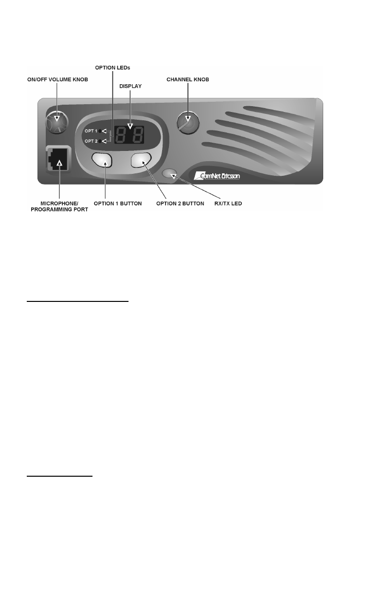
Figure 1 – PANTHER 300M mobile radio Front View
CONTROLS
All the controls for the Panther 300M mobile radio are located on the
front of the control unit and described below:
ON/OFF Volume Knob
This knob powers the radio ON/OFF and controls the volume level of
the received audio at the speaker. When the knob is in the OFF
position, rotate the knob clockwise until the knob clicks to turn the
power to the radio ON. To turn the power to the radio OFF, rotate the
knob counterclockwise until it clicks and stops. Rotate the knob
clockwise to increase the volume of receive audio. Rotate the knob
counterclockwise to decrease the volume of receive audio.
Typically, mobile radio installations require a vehicle ignition switch
to be in the Accessory or Run position before the radio will power
ON. In some applications, the radio is wired directly to the battery
and the radio will power ON regardless of the vehicle ignition switch
setting.
Channel Knob
This six position rotary knob selects the desired channel from a
programmed list of channels. Rotate the Channel Knob clockwise
or counterclockwise until the raised rib aligns with the desired
channel number. The displayed channel number is consistent with
the Channel Knob position.
11
Option 1 Button
This button can be programmed with a programmable function. The
default function is "Monitor/Clear.”
Option 2 Button
This button can be programmed with a programmable function. The
default function is "Disabled.”
Option Status LEDs
The two Option Status LEDs (Light Emitting Diodes) indicate the
state of the radio. The upper LED indicates the state of function
assigned to the Option 1 button. The lower LED indicates the state
of the function assigned to the Option 2 button.
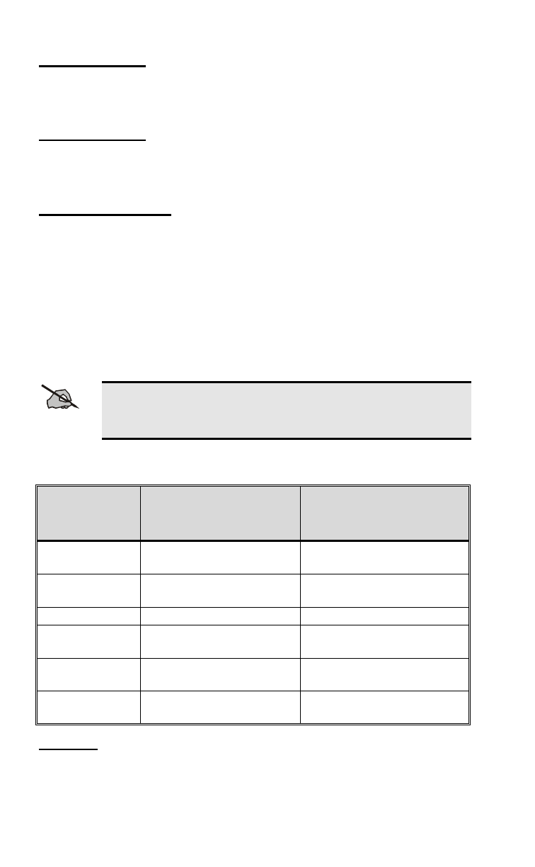
OPTION BUTTON FUNCTIONS
The following functions can be assigned to the Option 1 or Option 2
buttons.
NOTE
Press and hold the Option 1 or Option 2 buttons to execute
the programmed function.
Table 1: Programmed Functions States
FUNCTION 1 SHORT HIGH TONE
OPTION STATUS
LED ON
2 SHORT HIGH TONES
OPTION STATUS
LED OFF
Local/Distant
Squelch Local Distant
Type 99
ON/OFF ON OFF
Home Channel Home Channel Selected Channel
Horn Alert
ON/OFF ON OFF
Public Address
ON/OFF ON OFF
External/Internal
Speaker External Internal
Disabled
No function is assigned to the Option button. When pressed, the
radio will emit a Denied Alert Tone.

12
Local/Distant Squelch
The Local/Distant Squelch function toggles the channel squelch
setting between “Local” and “Distant”. “Local” squelch reduces the
number of received degraded transmissions. ”Distant" squelch
increases the number of received transmissions.
Type 99 ON/OFF
The Type 99 function toggles the state of the Type 99 Decoder
between “ON” and “OFF”. Type 99 mutes receive audio until a valid
Type 99 call is received. “ON” indicates the radio is operating in
Selective Call mode. ”OFF" indicates the radio is operating in
Monitor mode.
If an invalid or no Type 99 decode is programmed on a channel, the
Type 99 function is programmed for an Option button and the
Option button is pressed, the radio will emit a Denied Alert Tone.
Home Channel
The Home Channel function toggles the channel setting between
“Home Channel” and “Selected Channel”. “Home Channel” is a
programmed channel that allows direct communication with a
selected individual. “Selected Channel” is the channel frequency
selected by the user. Changing the channel selection knob or power
cycling the radio will cancel the Home Channel function.
Horn Alert ON/OFF
The Horn Alert ON/OFF function toggles the operation of the Horn
Alert of the Type 99 decoder between “ON” and “OFF”. "ON" will
activate the horn alert relay when a Type 99 Individual Call is
received. "OFF" will not activate the horn alert relay when a Type 99
Individual Call is received.
If an invalid or no Type 99 decode is programmed on a channel, and
the Horn Alert ON/OFF function is programmed for an Option
button, and the Option button is pressed, the radio will emit a
Denied Alert Tone.
Enabling the Horn Alert ON/OFF function will enable the Type 99
function. Disabling the Horn Alert ON/OFF function will not disable
the Type 99 function.
Public Address ON/OFF
The Public Address function toggles the operation of the Public
Address operation between “ON” and “OFF”. "ON" will send the

13
microphone audio through the receive amplifier to the external
speaker. "OFF" will send the microphone audio through the
transmitter.
External/Internal Speaker
The Internal/External Speaker function toggles the receive audio
between the “Internal” and “External” speaker. "External" activates
the speaker relay so the receive audio goes to the external speaker.
"Internal" does not activate the speaker relay so the receive audio
goes to the internal speaker.
HOOKSWITCH FUNCTIONS
Hookswitch functions are programmable and vary according to the
radio personality.
Table 2: Related Hookswitch Functions
MICRO-
PHONE CHANNEL
GUARD SQUELCH TYPE 99 HORN ALERT
FUNCTION
On-Hook Enabled Enabled Enabled
(Selective
Call Mode)
Resets the Horn
Alert function for
the next Type 99
Individual Call
Off-Hook Disabled Enabled Disabled
(Monitor
Mode)
Deactivates the
Horn Alert
function to
answer a Type
99 Individual Call
NOTE
Horn Alert and Internal/External Speaker options are mutually
exclusive of one another.

14
DISPLAY STATUS AND ERROR CODES
Table 3: Radio Status Indicators
LED Indicators: ●continuous flashing
DISPLAY TX/RX
LED TONE STATUS DESCRIPTION
3 mid tones Power-up
complete
1 short mid
tone Action Denied
1 short high
tone Programmed
function toggled
2 short high
tones Programmed
function toggled
continuous
low tone Fatal error
green 1 short tone Receiving Type
99 Individual Call Mid tone – CNE
Type 99
High tone – Other
Type 99
green 2 short
tones Receiving Type
99 Group Call Mid tone – CNE
Type 99
High tone – Other
Type 99
green 3 short
tones Receiving Type
99 Super
Group/Quick Call
Mid tone – CNE
Type 99
High tone – Other
Type 99
●red Transmitting
●green Receiving or
channel in use
1 - 6Channel
CCopyCat Mode
CC continuous
high tone Carrier Control
Timer Timeout Release the PTT.
EC Empty Channel Select another
channel or
reprogram the radio.
LC continuous
mid tone Locked Channel The channel is busy.
nA No Ignition Sense The Ignition A+ pin
is not receiving DC
power.
Pgreen Programming
Mode

15
LED Indicators: ●continuous flashing
DISPLAY TX/RX
LED TONE STATUS DESCRIPTION
PA Public Address Microphone audio is
routed through the
receiver audio PA to
the external
speaker.
Pd Power Down Software thermal
protection feature
has disabled the
transmitter.
PE amber Power Error Antenna failure or
PA failure.
UL continuous
mid tone Synthesizer
Unlocked Radio can not
transmit or receive
transmissions on a
particular frequency.
Return the radio for
service from a
qualified radio
technician.
E1 amber Personality
Checksum Error Reprogram the radio
with a valid
personality. If the
error persists, return
the radio for service
from a qualified
radio technician.
E2 amber Tracking Data
Error Return the radio for
service from a
qualified radio
technician.
E3 amber RF Power RF power is sensed
when the radio
should not be
transmitting. Return
the radio for service
from a qualified
radio technician.
E4 amber continuous
mid tone Synthesizer
Unlocked At
Power-Up
No lock on the
receive channel
frequency during
power-up.
Reprogram the radio
with a valid
personality. If the
error persists, return
the radio for service
from a qualified
radio technician.

16
LED Indicators: ●continuous flashing
DISPLAY TX/RX
LED TONE STATUS DESCRIPTION
E5 amber CopyCat Error Cloning operation
failed. If the error
persists, return the
radio for service
from a qualified
radio technician.
E6 amber Flash Software
Checksum Error Operating software
has been corrupted.
Return the radio for
service from a
qualified radio
technician.

17
BASIC OPERATION
SELECTING A CHANNEL
Rotate the Channel Knob clockwise or counterclockwise until the
raised rib aligns with the desired channel number.
TRANSMITTING A BASIC CALL
1. Power ON the radio.
2. Select a channel.
3. Ensure there is no activity on the channel by:
• checking the
TX/RX LED.
• pressing and holding the Monitor/Clear button. Squelch
noise will be heard if the channel is clear of traffic.
4. Remove the microphone from the hookswitch. Holding the
microphone approximately 2 inches from your mouth, press the
PTT button on the side of the microphone and speak in the
microphone.
NOTE
Speak in a normal volume. Shouting will degrade your
transmission.
5. Release the
PTT button after you have finished speaking.
PUBLIC ADDRESS MESSAGE
1. Verify that the
Option Status LED for the Option button
assigned with the Public Address function is ON. If it is not,
press the Option button.
2. Set the
ON/OFF Volume Knob to the desired public address
volume level. (Generally maximum volume.)
3. Remove the microphone from the hookswitch. Holding the
microphone approximately 2 inches from your mouth, press the
PTT button on the side of the microphone and speak in the
microphone.
4. When finished, replace the microphone on its hookswitch.
5. Set the
ON/OFF Volume Knob to the desired receive volume
level.
6. Verify that the
Option Status LED for the Option button
assigned with the Public Address function is OFF. If it is not,
press the Option button.

18
CHANNEL GUARD
Channel Guard is a method of reducing "channel chatter" by
equipping receivers with tone-responsive devices, which only allow
calls with the correct sub-audible tones to be heard by the user.
Channel Guard options and parameters are defined in the radio
personality.
The radio can be programmed on a per-channel basis to encode
and/or decode Channel Guard tones. Squelch Tail Elimination
(STE) can be enabled or disabled on a channel programmed with a
Channel Guard tone.
Channel Guard Monitor Function
The radio can be programmed, on a per-channel basis to transmit
with or without Channel Guard tones. STE can optionally be
enabled on a per-channel basis.
Ensure there is no activity on the channel by:
• checking the
TX/RX LED.
• pressing and holding the Monitor/Clear button. Squelch noise
will be heard if the channel is clear of traffic.
Digital Channel Guard
Digital Channel Guard performs similar to Channel Guard except
sub-audible code words are decoded and/or encoded. STE is
standard with Digital Channel Guard operation.
SENDING DTMF WITH THE DTMF MICROPHONE
The optional DTMF microphone allows the radio to send DTMF
signaling. DTMF may be used in a radio system to access a
telephone line or to perform system control functions.
1. Select a channel. DTMF must be enabled on the channel.
2. Ensure there is no activity on the channel by:
• checking the
TX/RX LED.
• pressing and holding the Monitor/Clear button. Squelch
noise will be heard if the channel is clear of traffic.
3. Remove the microphone from the hookswitch.
4. "Dial" the required DTMF digits from the telephone keypad on
the microphone. Do not hold the PTT button on the microphone

19
down while dialing. The DTMF microphone will automatically
key the transmitter.
5. Use the PTT button to transmit voice using the DTMF
microphone.

20
SELECTIVE SIGNALING
Selective signaling controls the muting and unmuting of the receive
audio. This allows a user or dispatcher to selectively call an
individual radio or group of radios. The PANTHER 300M mobile radio
supports selective signaling in Type 99 decode format.
In a selective signaling environment, the PANTHER 300M mobile radio
operates in one of two states, Monitor mode or Selective Call mode.
In the Monitor mode, the decoder is disabled and all calls are heard
by the user.
In the Selective Call mode, the decoder is enabled and only calls
intended for the user will be heard.
Selective signaling operates with or without Channel Guard. If
Channel Guard is enabled, the radio can be programmed with an
"And" or an "Or" option.
If the "And" option is programmed, only calls with the correct
selective signaling AND correct Channel Guard tones are heard by
the user.
If the "Or" option is programmed, calls with the correct Channel
Guard OR calls with the correct selective signaling and Channel
Guard tones are heard by the user.
A radio operating in Selective Call mode that receives a selective call
switches to the Monitor mode and the TX/RX LED flashes green.
The TX/RX LED indicates whether the channel has a carrier signal.
The following graphic depicts the flashing pattern of the TX/RX LED.
Monitor mode Without Carrier On
Off
Monitor mode With Carrier On
Off
TYPE 99 OPERATION
Type 99 is Com-Net Ericsson’s proprietary method for in-band, two-
tone sequential signaling. Type 99 is a conventional signaling

21
protocol that controls the muting and unmuting of a radio. Type 99
encoded base stations, mobiles, or portable radios can selectively
call individual units or groups of units in a conventional system.
Type 99 is used in paging operations; a dispatcher has the ability to
selectively call a radio or a group of radios.
If Type 99 is enabled in the radio personality, the radio can decode
Individual, Group and Supergroup Type 99 calls. See Table 3 for
radio indicator information for each of these types of calls.
Resetting Type 99 After A Call
After decoding a Type 99 call, the radio operates in Monitor mode
and all traffic on the channel is audible. If the channel has Channel
Guard, only the traffic with the radio's Channel Guard tone will be
heard.
To reset Type 99 operation, use one of the following methods:
• Press the
Monitor/Clear button.
• Press the
Option button, only if Option button is programmed
with Type 99 ON/OFF function.
• Allow the "Auto-Reset" timer to reset the Type 99 decoder (only
if the "Auto-Reset" timer in enabled in the radio personality).

22
PROGRAMMABLE PTT FUNCTIONS
CHANNEL BUSY LOCKOUT
The radio may be programmed with the Channel Busy Lockout
feature, which denies the use of the transmitter when the channel is
busy with traffic.
If the PTT button is pressed while the TX/RX LED is ON, the radio
will emit an alert tone until the PTT is released.
CHANNEL GUARD CHANNEL BUSY LOCKOUT
The radio may be programmed with the Channel Guard Busy
Lockout feature, which denies the use of the transmitter when the
channel is busy with another Channel Guard tone. The radio will
transmit when the channel is busy with the radio's Channel Guard
tone.
If the PTT button is pressed while the TX/RX LED is ON and the
radio is muted because of an incorrect Channel Guard tone, the
radio will emit an alert tone until the PTT is released.
TYPE 99 DISABLE AFTER PTT
The radio may be programmed with the Type 99 Disable After PTT
feature, which automatically disables the Type 99 decoder after a
transmission.
Use one of the methods outlined in the “Resetting Type 99 After A
Call” section to reset Type 99 operation.
IGNITION SENSE TX DISABLE
The radio may be programmed to deny the use of the transmitter if
there is no voltage on the Ignition A+ line. This feature prevents
unauthorized use of the radio and accidental high current battery
drain.

23
PROGRAMMABLE HORN ALERT FUNCTION
EXTERNAL ALARMS
The Car Horn Alert feature may be programmed to give one of three
alarms:
1. Single 1 second alarm
2. Three half second alarm pulses
3. Continuous alarm
RESETTING THE CAR HORN ALERT
Programmable features to reset the Car Horn Alert:
• Reset the Car Horn Alert after the Type 99 is reset.
• Automatically reset the Car Horn Alert.
CAR HORN ALERT IGNITION SENSE OPTION
The radio can be programmed to ignore the Car Horn Alert function
when Ignition A+ is present. Ignition A+ is usually connected to the
vehicle's ignition switch and indicates that the vehicle's engine is
running, or in the Accessory position.
The Car Horn Alert option provides notification to somebody outside
the vehicle that a Type 99 Individual Call has been received. When
the person is inside the vehicle, the Ignition A+ option automatically
disables the Car Horn Alert function.

24
CLONING
CopyCat™ Technology, a cloning feature, allows supervisor radios
to duplicate radio personalities into subordinate radios on-site
without a technician or PC. For more information about the CopyCat
Technology and configuration refer to the Panther 300 Series
Maintenance manuals, the On-Line Help in ProGrammer, or contact
your system administrator.

25
WARRANTY
A. Com-Net Ericsson Critical Radio Systems, Inc. (hereinafter "Seller") warrants to the
original purchaser for use (hereinafter "Buyer") that Equipment manufactured by or for the
Seller shall be free from defects in material, workmanship and title, and shall conform to
its published specifications. With respect to any Equipment not manufactured by or for the
Seller (except for integral parts of Seller's Equipment to which the warranties set forth
above shall apply), Seller gives no warranty, and only the warranty, if any, given by the
manufacturer shall apply. Batteries are excluded from this warranty but are warranted
under a separate Battery Warranty.
B. Seller’s obligations set forth in Paragraph C below shall apply only to failures to meet the
above warranties (except as to title) occurring within the following periods of time from
date of sale to the Buyer and are conditioned on Buyer’s giving written notice to Seller
within thirty (30) days of such occurrence:
1. for fuses and non-rechargeable batteries, operable on arrival only.
2. for parts and accessories (except as noted in B.1) sold by Seller’s Service Parts
Operation, ninety (90) days.
3. for PANTHER™ Series handportable and mobile radios, two (2) years.
4. for Cougar™ Series handportable and mobile radios, two (2) years.
5. for all other Equipment of Seller’s manufacture, one (1) year.
C. If any Equipment fails to meet the foregoing warranties, Seller shall correct the failure at
its option (i) by repairing any defective or damaged part or parts thereof, (ii) by making
available at Seller’s factory any necessary repaired or replacement parts, or (iii) by
replacing the failed Equipment with equivalent new or refurbished Equipment. Any
repaired or replacement part furnished hereunder shall be warranted for the remainder of
the warranty period of the Equipment in which it is installed. Where such failure cannot be
corrected by Seller’s reasonable efforts, the parties will negotiate an equitable adjustment
in price. Labor to perform warranty service will be provided at no charge during the
warranty period only for the Equipment covered under Paragraph B.3. To be eligible for
no-charge labor, service must be performed by an Authorized Service Center (ASC) or
other Servicer approved for these purposes either at its place of business during normal
business hours, for mobile or personal equipment, or at the Buyer’s location, for fixed
location equipment. Service on fixed location equipment more than thirty (30) miles from
the Service Center or other approved Servicer’s place of business will include a charge
for transportation.
D. Seller’s obligations under Paragraph C shall not apply to any Equipment, or part thereof,
which (i) has been modified or otherwise altered other than pursuant to Seller’s written
instructions or written approval or, (ii) is normally consumed in operation or, (iii) has a
normal life inherently shorter than the warranty periods specified in Paragraph B, or (iv) is
not properly stored, installed, used, maintained or repaired, or, (v) has been subjected to
any other kind of misuse or detrimental exposure, or has been involved in an accident.
E. The preceding paragraphs set forth the exclusive remedies for claims (except as to title)
based upon defects in or nonconformity of the Equipment, whether the claim is in
contract, warranty, tort (including negligence), strict liability or otherwise, and however
instituted. Upon the expiration of the warranty period, all such liability shall terminate. The
foregoing warranties are exclusive and in lieu of all other warranties, whether oral, written,
expressed, implied or statutory. NO IMPLIED OR STATUTORY WARRANTIES OF
MERCHANTABILITY OR FITNESS FOR PARTICULAR PURPOSE SHALL APPLY. IN
NO EVENT SHALL THE SELLER BE LIABLE FOR ANY INCIDENTAL,
CONSEQUENTIAL, SPECIAL, INDIRECT OR EXEMPLARY DAMAGES.
This warranty applies only within the United States.
Com-Net Ericsson Critical Radio Systems, Inc.
P.O. Box 2000
Lynchburg, VA 24501
1-800-528-7711
www.com-netericsson.com AE/LZT 123 3248/1 R4A

26
NOTES

27
NOTES

Com-Net Ericsson Critical Radio Systems, Inc.
P.O. Box 2000
Lynchburg, Virginia 24501
1-800-528-7711 (Outside USA, 804-385-2400)
www.com-netericsson.com Printed in U.S.A.