HARRIS TR-0011-A Panther 300M VHF (136-155 MHz) User Manual INstallation manual
HARRIS CORPORATION Panther 300M VHF (136-155 MHz) INstallation manual
HARRIS >
Contents
- 1. Operational manual
- 2. INstallation manual
- 3. Operation Manual
INstallation manual

360 Herndon Parkway
Suite 1400
Herndon, VA 20170
http://www.rheintech.com
Com-Net Ericsson Critical Radio Systems, Inc. Model: Panther 300M VHF (136-155 MHz)
FCC ID: OWDTR-00011-A 2001056 REV 1 / QRTL01-030 Page 42
FCC and Canadian Certification Report
APPENDIX E: INSTALLATION MANUAL

MM101031V2 R1A
PANTHER™ 300M VHF
Mobile Radio
Installation Manual

2
Copyright © 2001, Com-Net Ericsson Critical Radio Systems, Inc. All rights reserved.
This manual is published by Com-Net Ericsson Critical Radio Systems, Inc., without any
warranty. Improvements and changes to this manual necessitated by typographical errors,
inaccuracies of current information, or improvements to programs and/or equipment, may be
made by Com-Net Ericsson Critical Radio Systems, Inc., at any time and without notice.
Such changes will be incorporated into new editions of this manual. No part of this manual
may be reproduced or transmitted in any form or by any means, electronic or mechanical,
including photocopying and recording, for any purpose, without the express written permission
of Com-Net Ericsson Critical Radio Systems, Inc.
The software contained in this device is copyrighted by Com-Net Ericsson
Critical Radio Systems, Inc. Unpublished rights are reserved under the
copyright laws of the United States.
NOTICE!
Repairs made to this equipment should be made only by an authorized
service technician or facility designated by the supplier. Any repairs,
alterations, or substitution of recommended parts made by the user to this
equipment not approved by the manufacturer could void the user’s
authority to operate the equipment in addition to the manufacturer’s
warranty.
NOTICE!

3
TABLE OF CONTENTS Page
SAFETY INFORMATION...................................................................4
SAFETY TRAINING INFORMATION..............................................5
INTRODUCTION .................................................................................7
UNPACK AND CHECK THE EQUIPMENT ....................................7
OPTIONS AND ACCESSORIES........................................................8
INSTALLATION...................................................................................9
STEP 1 - PLAN THE INSTALLATION.............................................9
STEP 2 - LOCATE THE TOOLS REQUIRED...................................9
STEP 3 – EQUIPMENT PREPARATION........................................10
STEP 4 – PROGRAM THE RADIO .................................................15
STEP 5 – INSTALL CABLES...........................................................16
STEP 6 – INSTALL OPTIONS AND ACCESSORIES....................22
FIGURES
Figure 1 – Typical Connection Diagram................................................11
Figure 2 – Removing Top Cover ...........................................................12
Figure 3 – Factory Default Internal Speaker Jumper Setting (Enabled) 13
Figure 4 – Factory Default Settings For Jumper JP600 .........................14
Figure 5 – Removing Plastic Cover .......................................................15
Figure 6 – Power Cable RPM 113 7674/10...........................................17
Figure 7 – Mounting Bracket and Mounting Bracket Hardware Kit......20
Figure 8 – Mounting Bracket Installation..............................................21
Figure 9 – Mounting Radio to Bracket ..................................................22
Figure 10 - Mounting the External Speaker...........................................25
Figure 11 – External Speaker Option.....................................................26
Figure 12 – Internal/External Speaker Relay.........................................27
Figure 13 - External Car Alert ...............................................................29
Figure 14 - External Alarm Relay..........................................................29
Figure 15 – Ignition Sense Option.........................................................30
TABLES
Table 1 - PANTHER 300M Mobile Radio Options and Accessories .........8
Table 2 – Radio Option Connector P3 Interface Description ................23

4
SAFETY INFORMATION
The operator of any mobile radio should be aware of certain hazards
common to the operation of vehicular radio transmissions. A list of several
possible hazards is given:
1. Explosive Atmospheres - Just as it is dangerous to fuel a vehicle with
the motor running, similar hazards exist when operating a mobile radio,
be sure to turn the radio off while fueling the vehicle. Do not carry
containers of fuel in the trunk of the vehicle if the radio is mounted in
the trunk.
2. Interference to Vehicular Electronics Systems - Electronic fuel
injection systems, electronic anti-skid braking systems, electronic
cruise control systems, etc., are typical electronic systems that may
malfunction due to the lack of protection from radio frequency energy
present when transmitting. If the vehicle contains such equipment,
consult the dealer and enlist their aid in determining the expected
performance of electronic circuits when the radio is transmitting.
3. Dynamite Blasting Caps - Dynamite blasting caps may be caused to
explode by operating a radio within 500 feet of the blasting caps.
Always obey the "Turn Off Two-Way Radios" signs posted where
dynamite is being used.
When transporting blasting caps in your vehicle:
a. Carry the blasting caps in a closed metal box with a soft lining.
b. Leave the radio OFF whenever the blasting caps are being put into
or removed from the vehicle.
4. Liquefied Petroleum (LP) Gas Powered Vehicles - Mobile radio
installations in vehicles powered by liquefied petroleum gas with the
LP gas container in the trunk or other sealed-off space within the
interior of the vehicle must conform to the National Fire Protection
Association standard (NFPA) 58 requiring:
a. The space containing the radio equipment shall be isolated by a
seal from the space containing the LP gas container and its fittings.
b. Outside filling connections shall be used for the LP gas container.
c. The LP gas container shall be vented to the outside of the vehicle.
5
SAFETY TRAINING INFORMATION
WARNING
Your Com-Net Ericsson radio generates RF
electromagnetic energy during transmit mode. This radio
is designed for and classified as “Occupational Use Only,”
meaning it must be used only during the course of
employment by individuals aware of the hazards and the
ways to minimize such hazards. This radio is NOT
intended for use by the “General Population” in an
uncontrolled environment.
This radio has been tested and complies with the FCC RF exposure limits
for “Occupational Use Only.” In addition, your Com-Net Ericsson radio
complies with the following Standards and Guidelines with regard to RF
energy and electromagnetic energy levels and evaluation of such levels for
exposure to humans:
• FCC OET Bulletin 65 Edition 97-01 Supplement C, Evaluating
Compliance with FCC Guidelines for Human Exposure to Radio
Frequency Electromagnetic Fields.
• American National Standards Institute (C95.1 – 1992), IEEE Standard
for Safety Levels with Respect to Human Exposure to Radio Frequency
Electromagnetic Fields, 3 kHz to 300 GHz.
• American National Standards Institute (C95.3 – 1992), IEEE
Recommended Practice for the Measurement of Potentially Hazardous
Electromagnetic Fields – RF and Microwave.
CAUTION
To ensure that your exposure to RF electromagnetic
energy is within the FCC allowable limits for
occupational use, always adhere to the following
guidelines:
• DO NOT operate the radio without a proper antenna attached, as this
may damage the radio, and may also cause you to exceed FCC RF
exposure limits. A proper antenna is the antenna supplied with this
radio or an antenna specifically authorized by Com-Net Ericsson for
use with this radio.
• DO NOT transmit for more than 50% of total radio use time (50% duty
cycle). Transmitting more than 50% of the time can cause FCC RF
exposure compliance requirements to be exceeded. The radio is
transmitting when the “TX” LED in the radio’s display is illuminated.

6
Pressing the “PTT” button on the microphone will cause the radio to
transmit.
• ALWAYS use Com-Net Ericsson authorized accessories (antennas,
speaker/mics, etc.). Use of unauthorized accessories may cause the
FCC Occupational/Controlled Exposure RF compliance requirements
to be exceeded.
• ALWAYS keep at least 25 cm (10 inches) between the antenna and
user/bystanders while transmitting. This radio has been tested and
found to be compliant with Specific Absorption Rate (SAR) limits for
uncontrolled exposure at a distance of 25 cm (10 inches) or more using
a 50% duty cycle.
The information listed above is provided to make the user aware of an RF
exposure and what to do to assure that this radio operates within the FCC
RF exposure limits of this radio.

7
INTRODUCTION
The PANTHER™ 300M mobile radio is designed for installation as a front
mount radio. This manual provides the mobile installation instructions and
includes the instructions to install the external horn or external speaker
options.
UNPACK AND CHECK THE EQUIPMENT
Carefully unpack the equipment and verify the items listed below are
included in the shipping container. If damage has occurred to the
equipment during shipment, file a claim with the carrier immediately.
Table 1 on page 8 provides a complete list of the options and accessories
available for the PANTHER 300M mobile radio.
PANTHER 300M Radios Are Shipped With The Following:
• PANTHER 300M Mobile Radio..........................KRD 103 154/(1-7)
• Power Cable.......................................................RPM 113 7674/10
• Mounting Bracket..............................................KG6903
• Mounting Bracket Hardware Kit .......................52B6032
• Operator's Manual..............................................MM101030V1
• Installation Manual............................................MM101031V1

8
OPTIONS AND ACCESSORIES
The following table lists the options and accessories available for the
Panther 300M Mobile Radio.
Table 1 - PANTHER 300M Mobile Radio Options and Accessories
DESCRIPTION PART NUMBER OPTION
NUMBER
Microphone, Standard KRY 101 1654/1 KAMC7J
Microphone, DTMF KRY 101 1654/10 KAMC7K
Microphone Hanger 344A4678P1 KAMN1A
External Speaker (4 ohm, 10W) 19A149590P11 KALS1H
Option Cable RPM 113 7674/1 KACJ7G
External Relay Kit 19A705499P1 KASU1C
Noise Suppression Kit 19A148539G1 KAPD1A
Power Cable RPM 113 7674/10 KACJ7H
Audio Test Cable RPM 113 2472/48
Conventional ProGrammer Software
or AE/LZY 213 766/5 TQ3389 R9A
or later
ProGrammer Software AE/LZY 213 766/1 TQ3385 R9A
or later
Radio Programming Interface Cable RPM 113 2472/47 TQ3393
Copy CatTM Cable, 300M-to-300M RPM 113 2472/42 TQ3394
Copy CatTM Cable, 300M-to-300P RPM 113 2472/41 TQ3395

9
INSTALLATION
STEP 1 - PLAN THE INSTALLATION
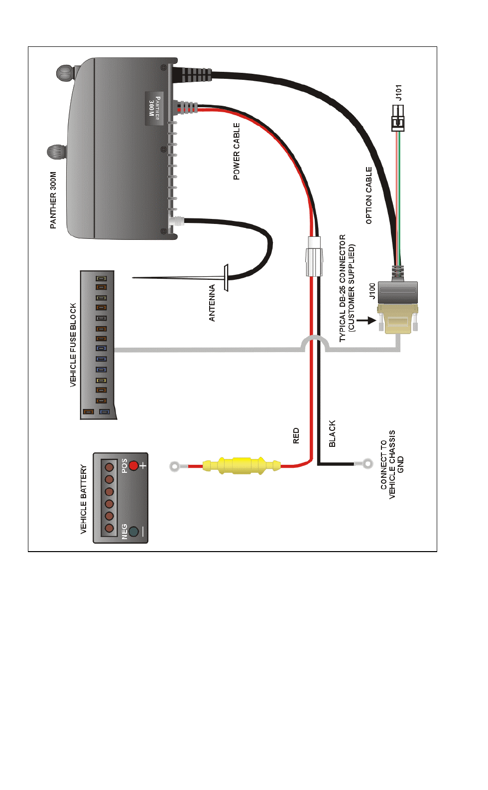
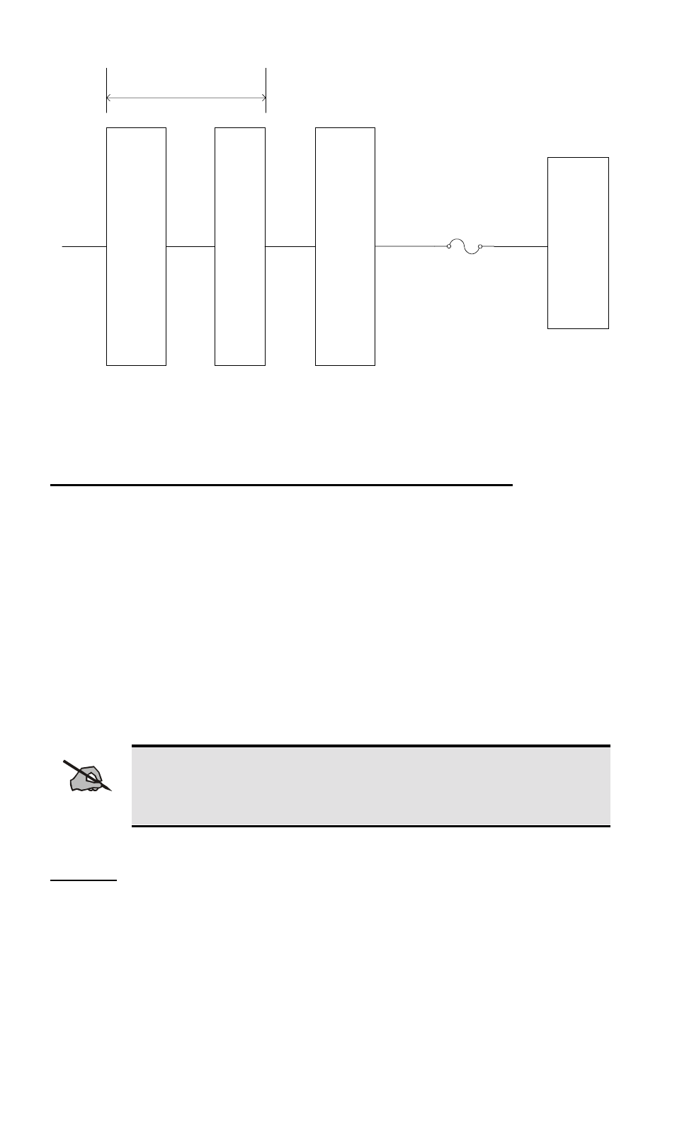
Figure 1 shows an example of a typical connection diagram. Before
beginning, plan the radio installation carefully so that it will:
Be safe for the operator and passengers,
Be convenient for the operator to use,
Be neat in appearance,
Be protected from water damage,
Be easy to service,
Be out of the way of auto mechanics,
Be out of the way of passengers, and
Allow for good air flow around the unit’s cooling fins.
For passenger safety, mount the radio securely so the unit will not break
loose in the event of a collision. This is especially important in station
wagons, vans and similar type installations where a loose radio could be
extremely dangerous to the vehicle occupants.
The procedures in this section provide a guideline for installing the mobile
radio. In some applications, it may be necessary to deviate slightly from the
recommended procedure and the order in which the equipment is installed.
To assure the feasibility of the cable routes you plan to use, it is suggested
that you run the cables before installing the radio. Be sure to leave some
slack in each cable so that the radio may be pulled out for servicing with the
power applied.
It is recommended the unit be installed by one of the many Com-Net
Ericsson Authorized Service Centers located throughout the United States.
Personnel at these centers are experienced in installations of this type and
can provide a safe, neat, and functional installation.
STEP 2 - LOCATE THE TOOLS REQUIRED
The following tools are required to install the PANTHER 300M Mobile
Radio:
• Electric drill for drilling mounting holes
• Drills and circle cutters as follows:
No. 31 (1/8-inch) drill

10
1/2-inch drill or circle cutter
3/4-inch circle cutter, hole saw or socket punch
• Phillips and flat-blade screwdrivers
• No. 10 Torx driver
Torx is a registered trademark of CAMCAR Division TEXTRON, Inc.
STEP 3 – EQUIPMENT PREPARATION
Mounting
This section describes the radio preparation for installation. In most
applications, the following procedures should be completed before the radio
is mounted. Depending upon the mounting location, these procedures could
become very difficult after the radio is mounted. The preparation list
includes:
• Configuring the Internal Speaker Jumper
• Configuring the Ignition Sense Line Jumper
• Connecting the Option Cable to the Radio
Read through the procedures provided in this section. If you are satisfied
with the default factory jumper settings and your installation does not
require an option cable, skip this section and go to STEP 4 – PROGRAM
THE RADIO on page 15.
Removing the Top Cover and Shield
The top cover and shield must be removed to change the Internal Speaker
jumper (JP701) or the ignition sense line jumper (JP600), to connect the
option cable to the radio.
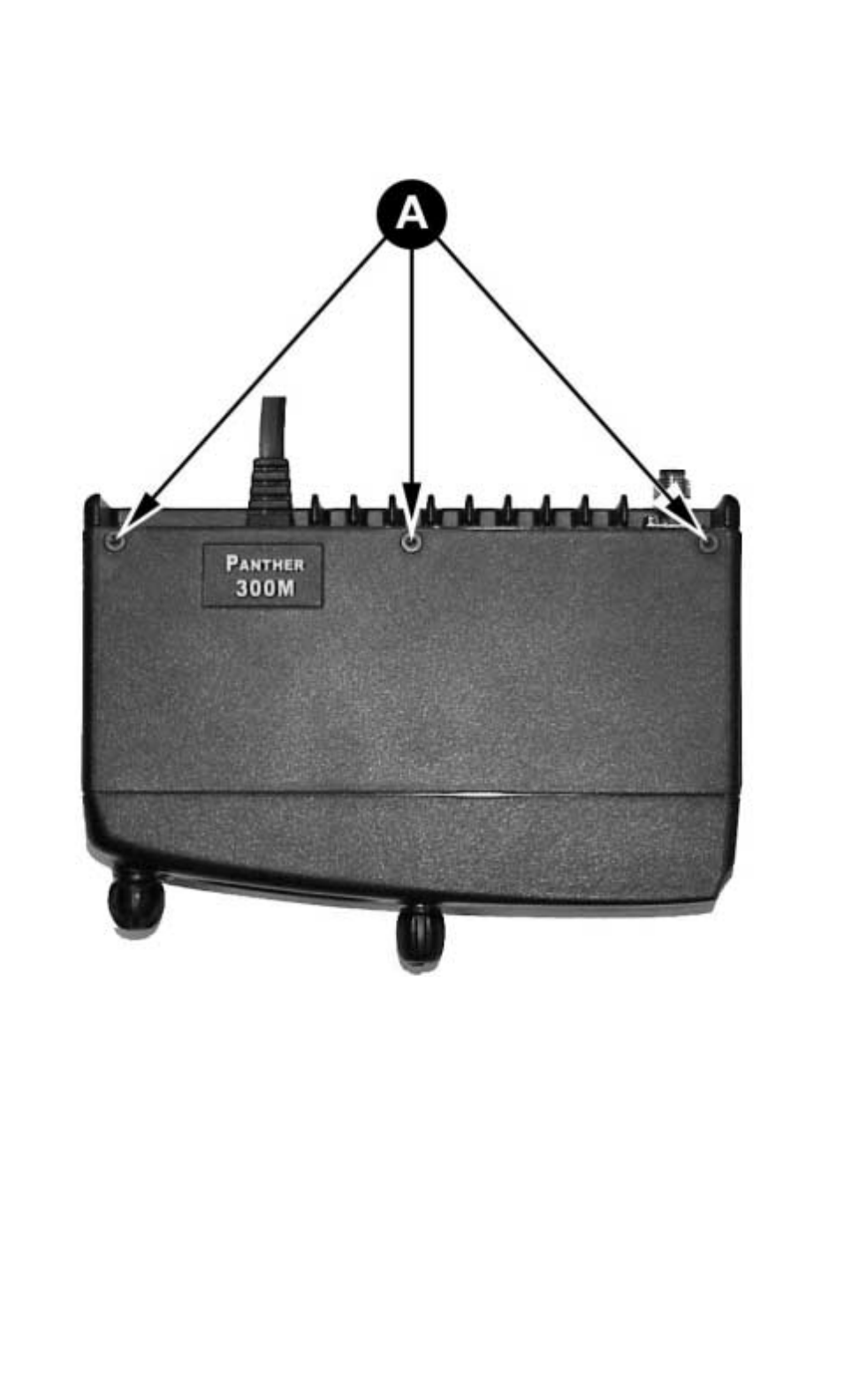
1. The top cover is secured with three screws from the bottom of the
radio. Using a No. 10 Torx driver, loosen the three screws on the
top of the radio as shown in Figure 2.
2. Remove the two control knobs from the front of the radio.
3. Pry the cover loose from the two tabs on the bottom of the radio.
11
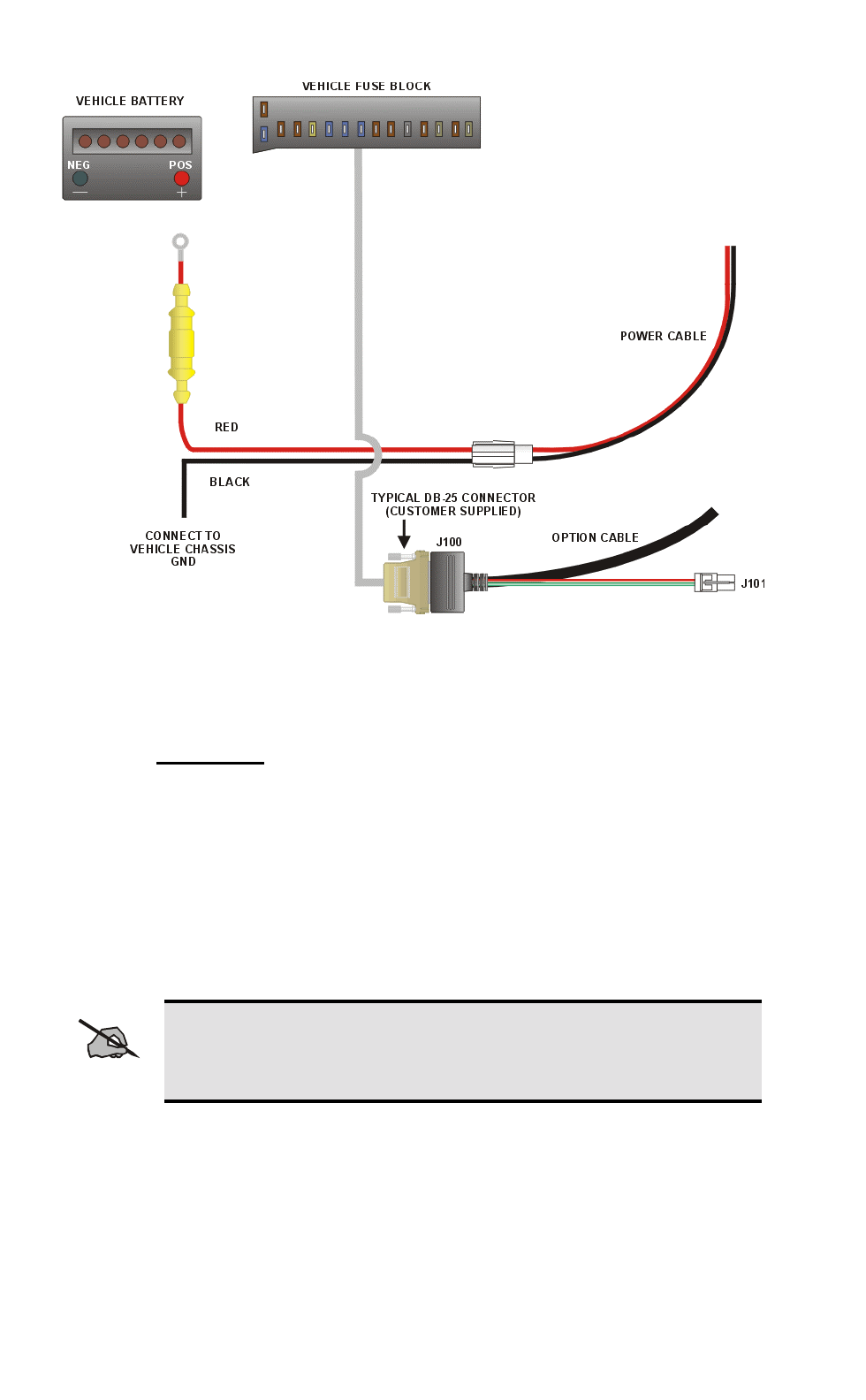
Figure 1 – Typical Connection Diagram
12
4. Remove the top cover by lifting the back and sliding it forward away
from the chassis.
Figure 2 – Removing Top Cover
13
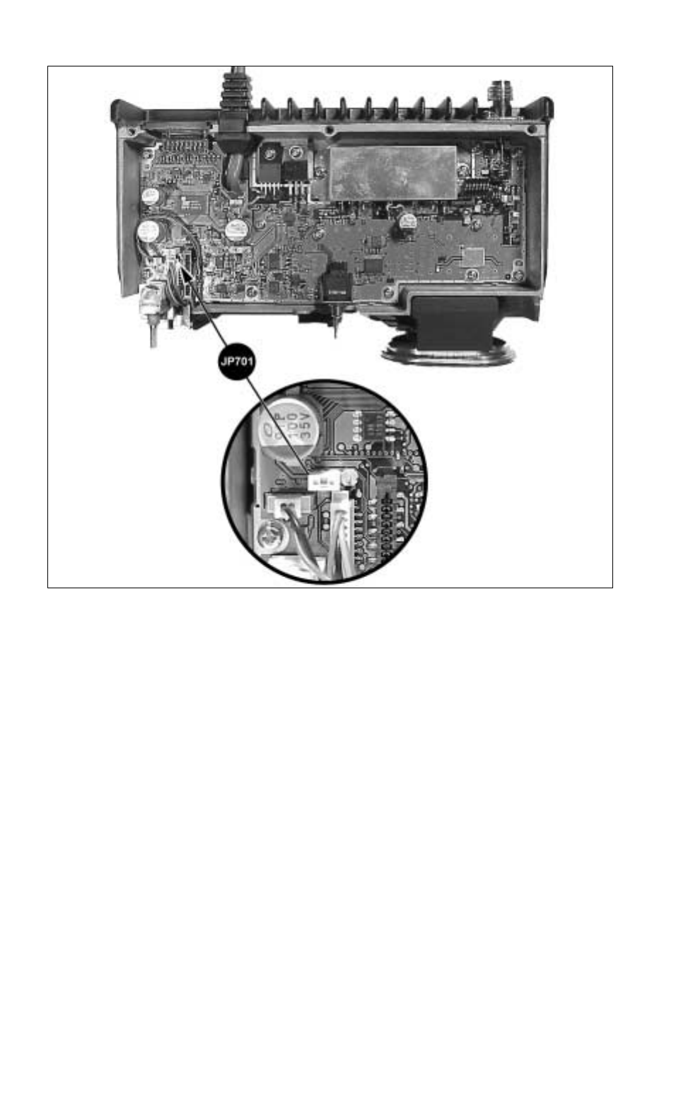
Figure 3 – Factory Default Internal Speaker Jumper Setting (Enabled)
Configure the Internal Radio Speaker Jumper (JP701)
The PANTHER 300M radio is shipped from the factory with the internal
radio speaker jumper (JP701) set to 1-2 as shown in Figure 3. This setting
enables the internal radio speaker. Set the jumper to 2-3 if 1) only the
External Speaker is to be enabled or 2) the Internal/External Speaker option
is to be enabled.
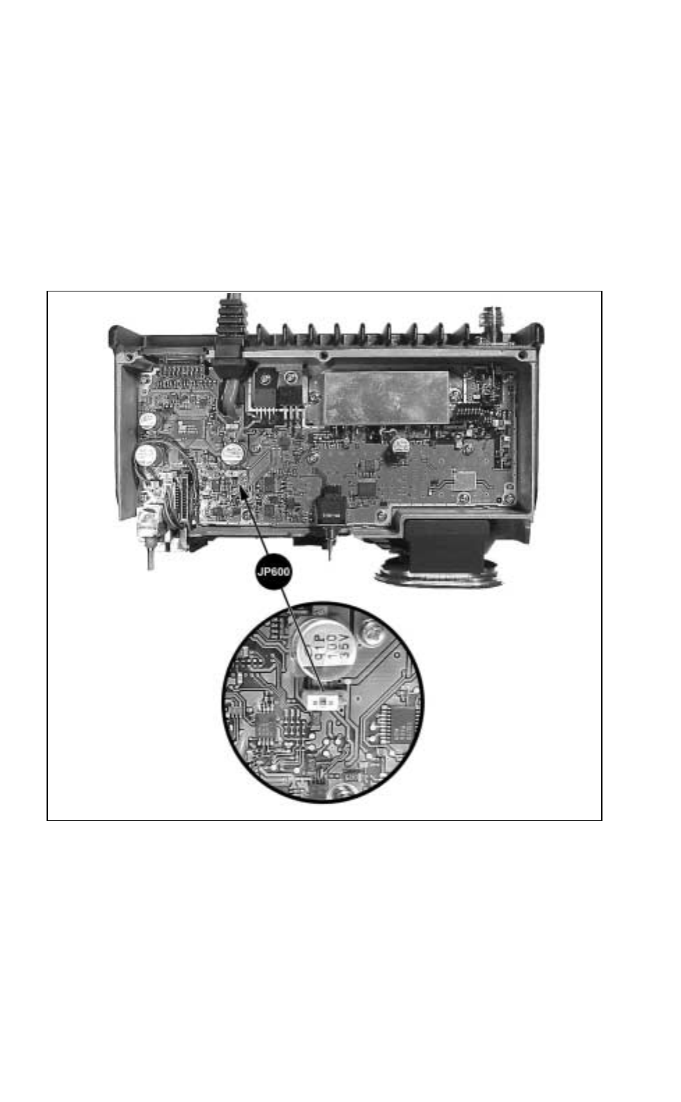
Configure Ignition Sense Jumper (JP600)
The Ignition Sense line enables or disables transmit or car horn alert option
through the vehicle ignition switch. If the Ignition Sense option is desired,
Ignition Sense jumper JP600 must be set to 2-3. The PANTHER 300M radio
is shipped from the factory with the Ignition Sense jumper (JP600) set to 1-
2 as shown in Figure 4. This default setting disables the Ignition Sense
option. If your installation will not take advantage of the Ignition Sense
line, skip this section and proceed to the next section.
To use the Ignition Sense line in any application, the option cable must be
14
wired accordingly, see the section Connect To Ignition Sense on page 17.
There are three parameters that define how the Ignition Sense feature will
operate - a jumper on the radio (as described above), and two programmable
parameters in the personality.
The programmable parameters enable/disable Transmission and/or Horn
Alert with respect to the vehicle ignition switch. For more information on
the personality parameters, see the On-Line Help in Conventional
ProGrammer (TQ-3389 R9A or later) or ProGrammer (TQ-3385 R9A or
later).
Figure 4 – Factory Default Settings For Jumper JP600
15
Connect Option Cable
This section applies to installations that require an option cable. The option
cable (RPM 113 7674/1) is required if you are installing:
• External Speaker • Internal/External Speaker Option
• Car Horn Alert • Ignition Sense
• External Modulation • External Demodulation
To connect the option cable to the radio:
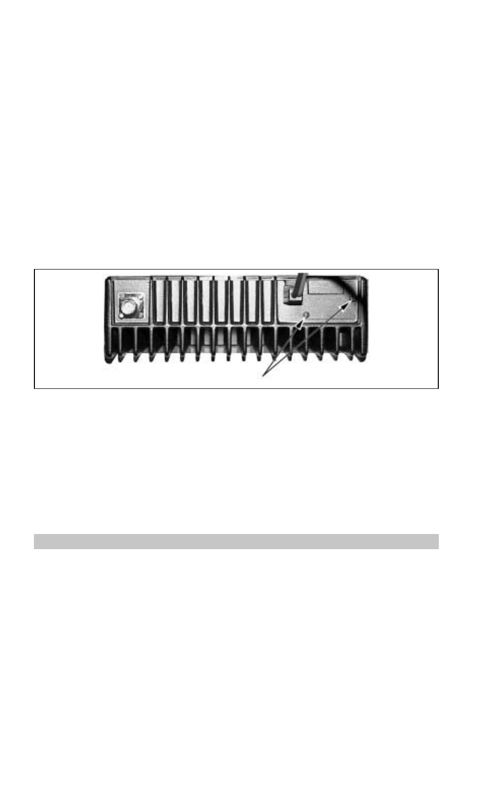
1. Remove the two Phillips screws holding the plastic cover in place, from
the back of the radio, see Figure 5.
Figure 5 – Removing Plastic Cover
2. Insert the option cable through the hole left by removing the plastic
cover. This will allow the connector to fit through the hole in the back
of the radio.
3. Plug the option cable connector into J3 on the radio circuit board.
4. Finally, attach cable with the two Phillips screws.
STEP 4 – PROGRAM THE RADIO
All radios must be programmed with a radio personality. There are many
parameters in the PANTHER 300M mobile radio that need to be setup and
defined for the radio to operate appropriately for each application.
Conventional ProGrammer (TQ-3389 R9A or later) or ProGrammer (TQ-
3385 R9A or later) is the software used to create the personality for the
PANTHER 300M radio. The radio personality is a computer file that defines
all the operating parameters for the radio. For more information on
programming the PANTHER 300M radio, see the On-Line Help provided
with Conventional ProGrammer (TQ-3389 R9A or later) or ProGrammer
(TQ-3385 R9A or later). Typically, the radio is programmed before it is
installed in a vehicle.

16
STEP 5 – INSTALL CABLES
The PANTHER 300M Mobile Radio is installed as a front mount radio. The
location of the mount, the application, and the options to be installed should
be considered when planning the cable runs. The cable diagram in Figure 1
should be referenced throughout the installation process.
Power Cable
The power cable RPM 113 7674/10 consists of a two-wire cable, see Figure
6. The red fused lead supplies power to the radio directly from the vehicle
battery. Ignition Sense lead, through the separate option cable, is used by
the radio electronics to determine when the ignition switch is turned on.
The black lead is the radio ground connection.
To install the power cable:
1. Remove the fuse from the power cable.
2. When the power cable is wired directly to the vehicle’s battery, it is
necessary to route the red power lead through the vehicle’s firewall. If
an existing hole is not conveniently located in the firewall, drill a 1/2-
inch hole in the firewall for the cable run and insert a rubber grommet.
This grommet is required to prevent lead chaffing. Additional
grommets may be required if the leads must pass through shields or
guards in the engine compartment.
17
Figure 6 – Power Cable RPM 113 7674/10
Route the lead away from high heat sources in the engine compartment
that may cause lead damage and introduce a fire hazard. In addition, the
lead should not be routed near electrical noise sources such as
electronic ignition modules or cruise control modules.
3. Secure the cable at several locations within the engine compartment to
prevent possible damage to the cable.
4. Connect the BLACK lead to the vehicle chassis. Connect the lead as
close to the radio as possible. DO NOT connect the BLACK lead to
the “NEG” or “-“ battery post. Connect the RED lead to the positive
(“POS” or “+”) battery post. See Figure 6.
NOTE
The power source must have a minimum current supply
capability of 13 amps.

18
Connect To Ignition Sense
The ignition sense line is used to enable or disable transmit or the Car Horn
Alert option through the vehicle ignition switch. For a detailed description
on how to configure the Ignition Sense line, see the section Configure
Ignition Sense Jumper on page 13. Regardless of how the ignition sense
line is configured, the option cable must be wired as described below for the
feature to work.
Connect Pin 13 of the option cable to an ignition “ON” sense point
(preferably an “Accessory” point in the vehicle fuse panel) that is switched
on when the vehicle ignition switch is in the ACCESSORY and RUN
positions. This lead should be connected so the vehicle fuse protection is
used. See Figure 6.
NOTE
The DB-25 male connector that connects to the option cable is
user-supplied.

19
CAUTION
The “Accessory” point should drop to ZERO volts when
cranking the engine and return to +12 volts after the
engine is started. If a point is chosen that drops to a
voltage between zero and +12 volts, the radio may
execute a power-up cycle several times during start up. It
is recommended that the terminal be measured with a
voltmeter to be sure it shuts OFF (goes to zero volts)
during the cranking of the engine.
Certain problems may be encountered when accessory
equipment is connected to the ignition or accessory lines
of the vehicle, where these lines may have large filter
capacitors and a leakage path present. If the radio does
not turn OFF within a reasonable amount of time after the
ignition is turned off, first try a different accessory or
ignition A+ pick up point in the vehicle. Many vehicles
have more than one circuit that is switched by the ignition
switch, and one may be available that does not have large
filter capacitors or a leakage path present.
If a different pickup point cannot be found, then add a
470-ohm, 1-watt resistor from the ignition A+ pick point
to ground. This will discharge the capacitor(s) or reduce
the leakage voltage to a low value. Current drain through
this resistor will be minimal (less than 0.03A) when the
ignition is switched ON.
20
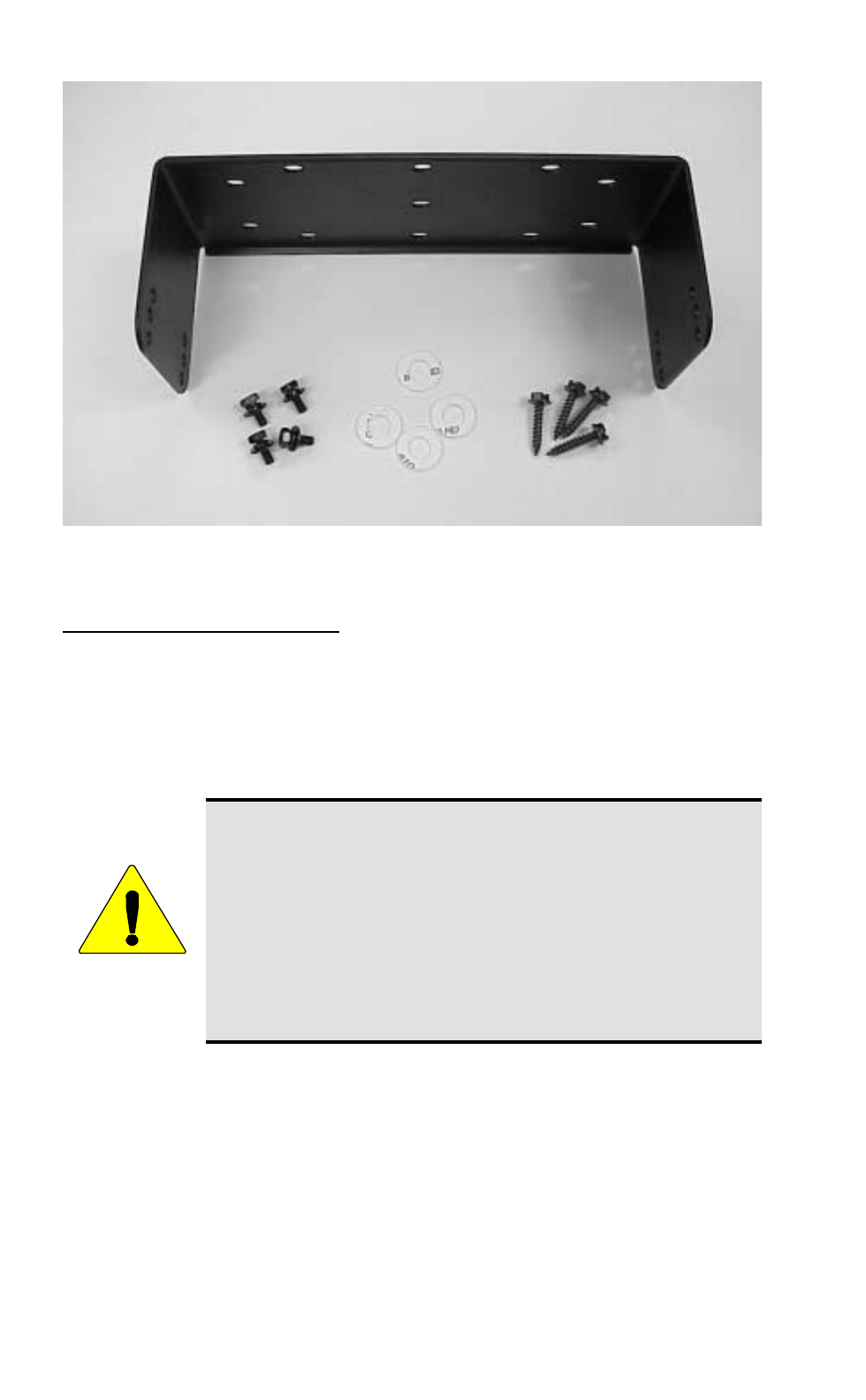
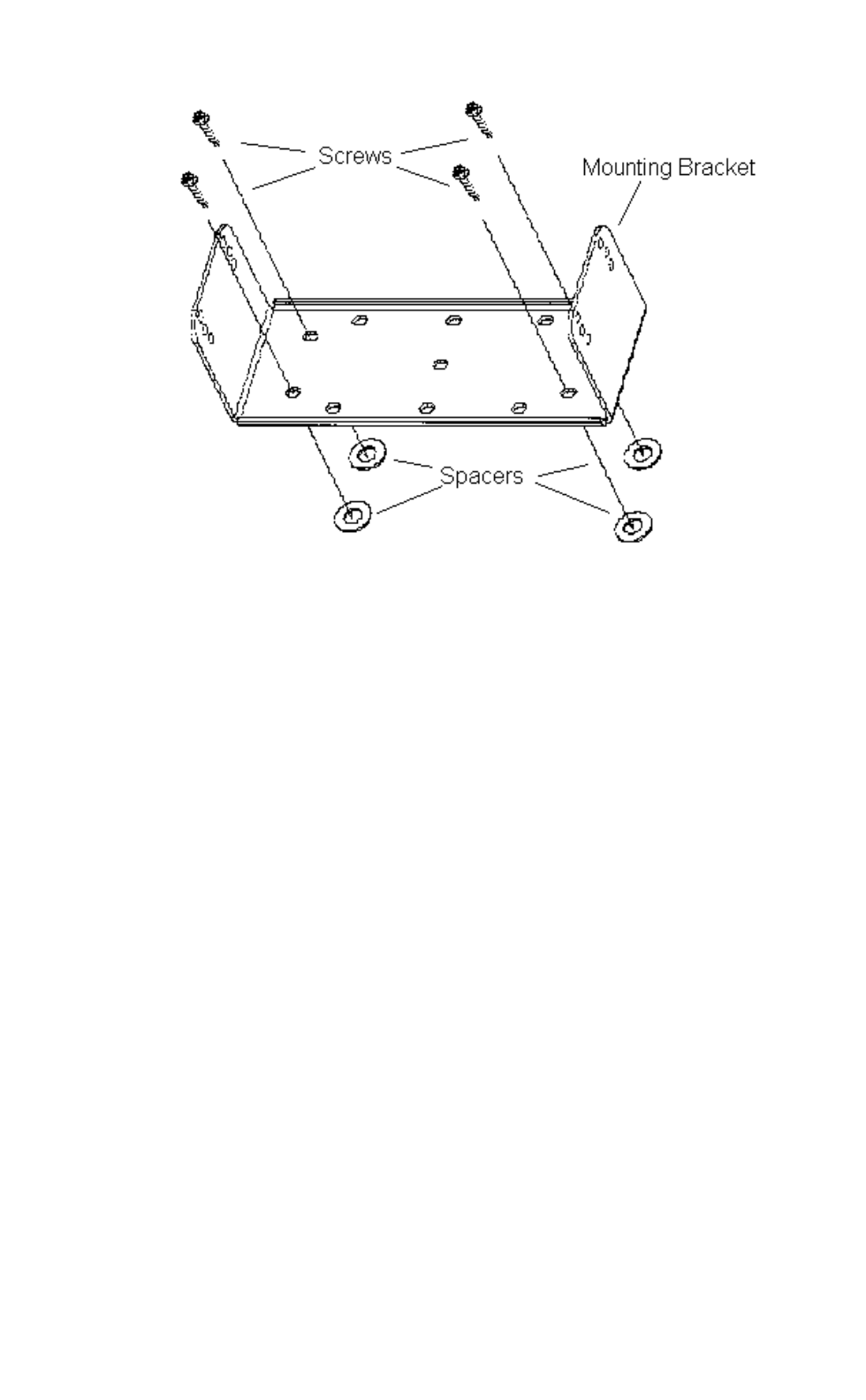
Figure 7 – Mounting Bracket and Mounting Bracket Hardware Kit
Radio Mounting Procedures
The following procedures are used to mount the radio.
1. Using the bracket as a template, mark and drill the mounting holes
using a No. 31 (1/8) drill bit. Be sure to leave enough room at the rear
of the radio unit for the cable connections and airflow.
CAUTION
Be careful to avoid damaging some vital part (fuel tank,
transmission housing, etc.) of the vehicle when drilling
mounting holes. Always check to see how far the
mounting screws will extend below the mounting surface
before installing.
If pilot holes must be drilled, remove all metal shavings
from drilling holes before installing screws.
2. Mount the bracket using the four 3/4” Phillips sheet metal screws and
spacers provided in the mounting bracket hardware kit. (Refer to
Figure 8.)
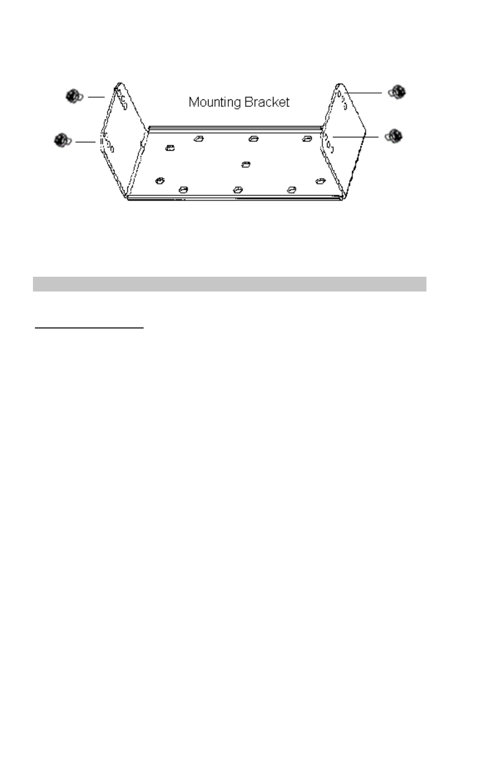
21
Figure 8 – Mounting Bracket Installation
3. Place the radio into the mounting bracket and secure with the four 3/8”
Phillip’s screws supplied. The radio can be fastened in any of three
different positions: parallel to the mounting surface or tilted slightly
from the parallel position. (Refer to Figure 9.)
4. Connect antenna coaxial cable to antenna connector (TNC).
5. Insert power cable into power connector running from rear of radio unit
and push until the connectors snap together.
6. Recheck all connections and then reinsert fuse into the fuse assembly
on the power cable.
22
Figure 9 – Mounting Radio to Bracket
STEP 6 – INSTALL OPTIONS AND ACCESSORIES
Radio Option Cable
The radio option cable (RPM 113 7674/1) is required if you are installing:
• External Speaker • Internal/External Speaker Option
• Car Horn Alert • Ignition Sense
• External Modulation • External Demodulation
The section STEP 3 – EQUIPMENT PREPARATION, on page 10,
describes how to connect the option cable to the radio. The other end of the
option cable consists of a standard female DB-25 connector, which is used
to connect to the optional accessories listed above. Table 2 provides a
description for each input and output on the radio option connector J603.
23
Table 2 – Radio Option Connector P3 Interface Description
DB-25
PIN
NO
(J100)
PIN
NO
(P3)
I/O DESCRIPTION
2 1 --- Ground:
Audio Ground
52I
Internal Speaker Input #1:
5W across Internal Speaker
63O
Audio Amp Output #1:
Vo ≈ 6.6 VDC
18 4 O Audio Amp Output #2 to Internal or External Speaker
Vo ≈ 6.6 VDC; 10W maximum across External Speaker
19 5 I External Mic Input:
300-3000 Hz
Input level @ 1kHz for 60% of RSD: 82 ± 28 mVRMS
(if external audio source has Ro=600Ω)
Input level @ 1kHz for 60% of RSD: 41 ± 14 m VRMS
(if external audio source has Ro<1Ω)
76I
External Mod Input:
5-10,000 Hz (3 db BW)
Modulation-Sensitivity: 4.2 kHz/Vrms ± 3dB
20 7 O Switched DC Output:
Icc=500 mA Max
88I
Push To Talk:
TX ON: Low
TX OFF: Open
21 9 I Mic Hookswitch:
“Disable” or “Enable” is selected by PC Programmer
Hookswitch ON: Low
Hookswitch OFF: Open
910O
Rx Discriminator Detect Audio:
20-4,000 Hz (3 dB Bandwidth)
75 m VRMS ±3 dB into a 10K ohm load
22 11 --- Ground
10 12 I Internal Mic Mute:
Mute ON: Low
Mute OFF: Open
23 13 O Radio UnSquelch:
Squelch Open: Low
Squelch Close: High
RL = 4.7 kohms
11 14 Spare
24
Table 2 - Radio Option Connector P3 Interface Description Cont’d
DB-25
PIN NO
(J100)
PIN NO
(P3) I/O DESCRIPTION
24 15 O (1) HORN CONTROL At Signaling Mode
Display In Menu Action
On Enable
Off Disable
When select “ON”(enable) and a correct T99 Individual Call
is received, the output of pin 15 is “low.”
Horn Alarm ON : Low
Horn Alarm OFF: Open
(2) SPEAKER SELECT INTERNAL/EXTERNAL
Enabling or disabling of the Internal/External Speaker option
is done by proper setting of an internal jumper in the mobile
radio.
Internal: Low
External: Open
For relay control Io_max = 150mA
**“HORN CONTROL” or “SPEAKER SELECT” is
selected by PC ProGrammer.
Note: Internal and external speaker do not operate
simultaneously.
12 16 I Data Communication Input (Test Mode)
TTL Level
25 17 O Data Communication Output (Test Mode)
TTL Level
13 18 I Ignition Sense
13.6VDC
Io_max = 100 mA
NOTE
Internal Mic Mute (DB25-10) must be grounded when
applying audio to external Mic Input (DB25-19).
External Mic Input (DB25-19) has the same audio
characteristics as the Front Panel Mic Jack. External Mod
Input (DB25-7) has no pre-emphasis or modulation limiting.
25
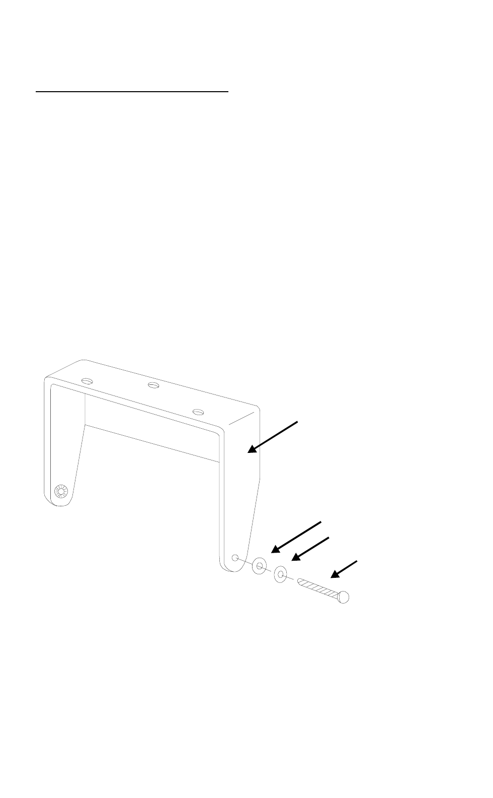
External Speaker – 19A149590P11
The external speaker kit includes a 4-ohm, 10 Watt rated speaker and a
radio option cable. To connect an external speaker, the radio option cable
(RPM 113 7674/1) must be installed and connected to the radio.
1. Mount the speaker so it is directed at the operator but does not interfere
with the operator’s vision. It also should not present a hazard in the
event of an accident. The speaker may be mounted on the lower edge of
the instrument panel, the firewall, or above the windshield in some
trucks.
2. Use the mounting bracket as a template for locating the mounting
holes, and mount the speaker as shown in Figure 10.
3. Refer to Figure 9 for instructions on connecting the External Speaker
option and Figure 10 for instructions on connecting the
Internal/External Speaker option.
MOUNTING
BRACKET
MACHINE
SCREW
FLAT WASHER
LOCK WASHER
Figure 10 - Mounting the External Speaker
26
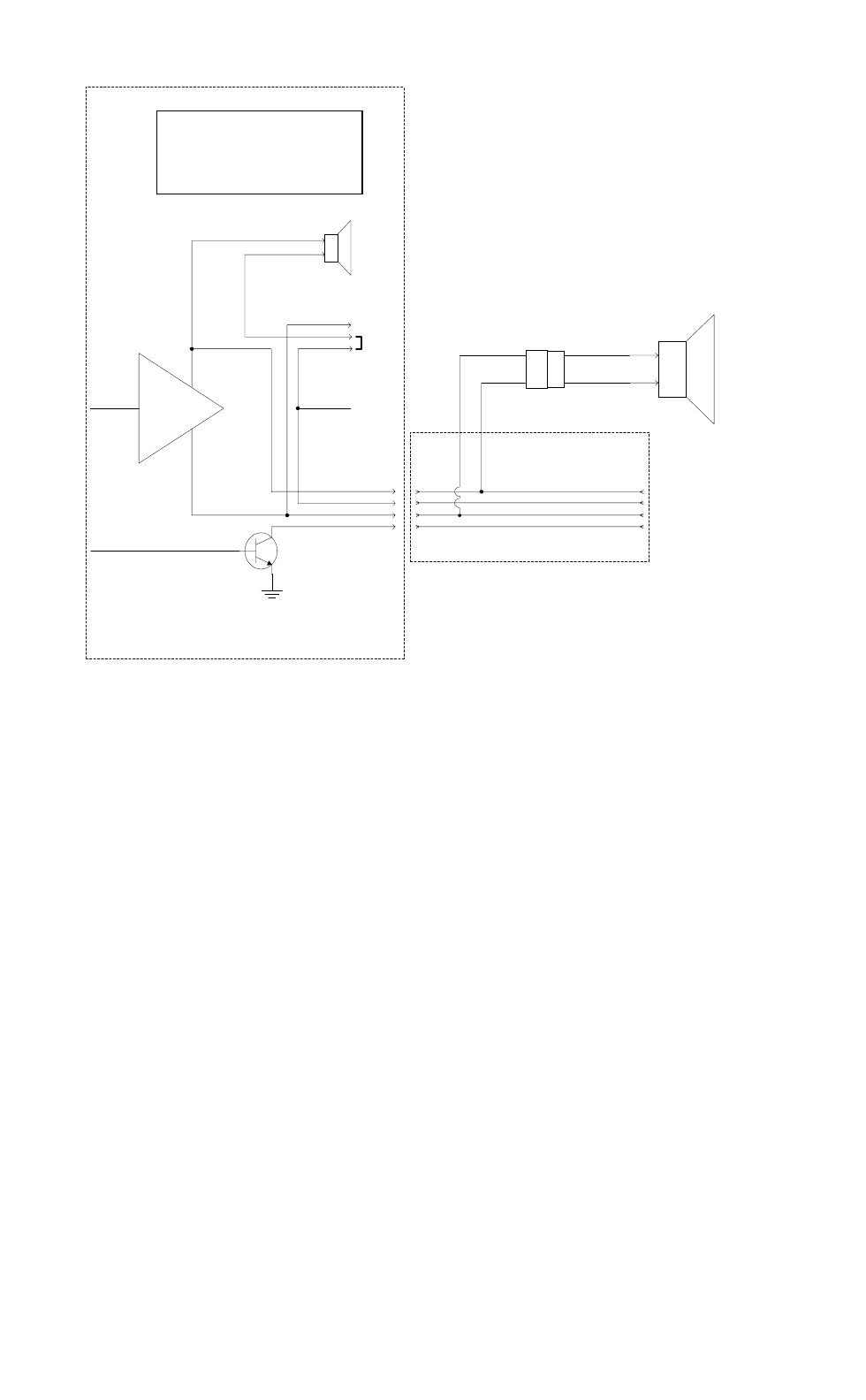
PANTHER 300M EXTERNAL
SPEAKER OPTION
WHEN THE EXTERNAL SPEAKER OPTION IS APPLIED,
AUDIO FROM THE SPEAKER AMP LEAVES THE RADIO
ON OPTION CONNECTOR PINS 3 AND 4 AND GOES TO
J101. THE EXTERNAL SPEAKER'S CABLE IS
CONNECTED TO J101.
JUMPER POSITIONS
1-2 USED WHEN THERE IS NO
EXTERNAL SPEAKER OPTION
2-3 USED WHEN THERE IS AN
EXTERNAL SPEAKER OPTION
-
+
AUDIO IN
RADIO AUDIO
AMP
INTERNAL
SPEAKER
3 PIN
JUMPER
uP PORT
OPEN COLLECTOR
TRANSISTOR
HORN/SPKR 15
SPKR 1 3
INT SPKR 1 2
SPKR 2 4
INT SPKR 1
3
2
SPKR 1 1
SPKR 2
SPKR 2
SPKR 1
8 OHM
5 WATT
INT
EXT
300M RADIO
RPM 113 7674/1
OPTION CABLE
RADIO
CONNECTOR DB 25
CONNECTOR
4
2
3
15
18
5
6
24
P3 J100
4 OHM
10 WATT
J101 SPKR 1
SPKR 2
Figure 11 – External Speaker Option
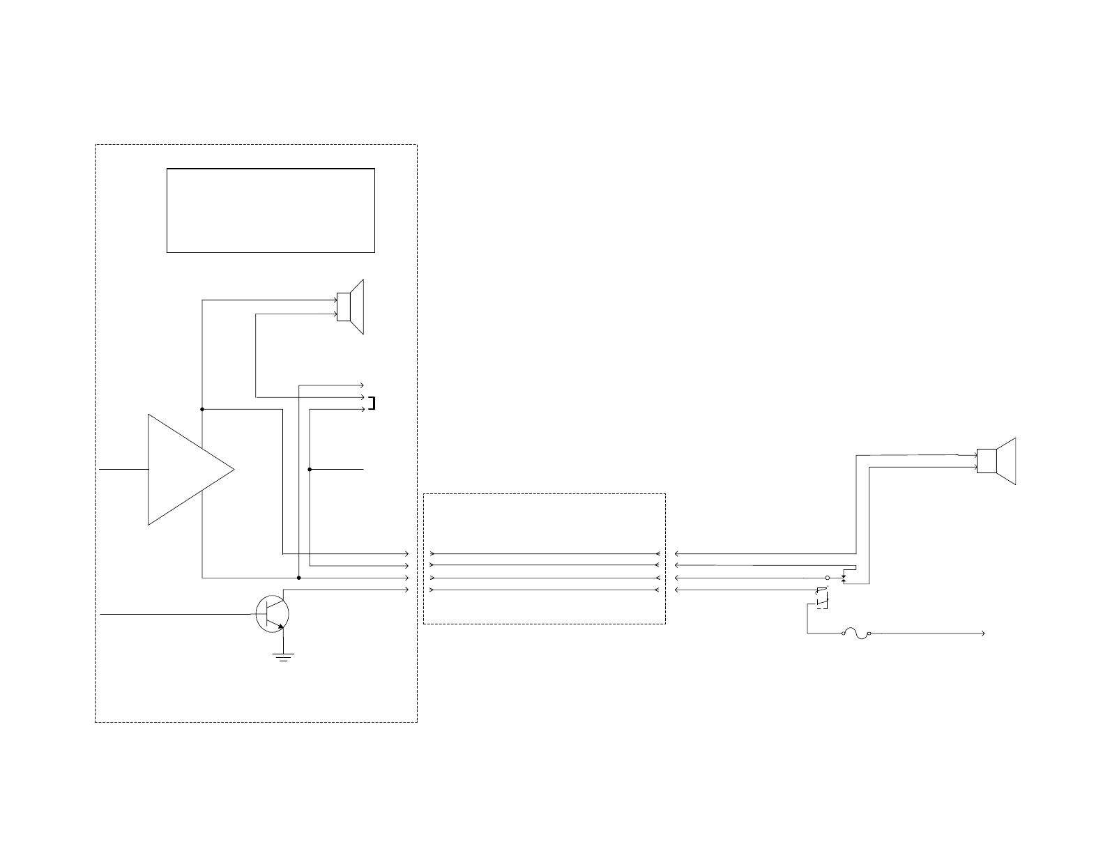
PANTHER 300M INTERNAL/EXTERNAL
SPEAKER OPTION
(THIS SCHEMATIC ALSO APPLIES TO PUBLIC ADDRESS)
WHEN THE INTERNAL/EXTERNAL SPEAKER OR PUBLIC ADDRESS OPTIONS ARE APPLIED. AUDIO FROM THE SPEAKER AMP
LEAVES THE RADIO ON OPTION CONNECTOR PIN 3 AND GOES TO THE COMMON SIDE OF AN SPDT RELAY.
WHEN INTERNAL SPEAKER IS SELECTED, THE RELAY FLOATS. THE NORMALLY CLOSED RELAY CONTACT APPLIES AUDIO
BACK INTO THE RADIO TO THE INTERNAL SPEAKER ON OPTION CONNECTOR PIN 2. (IT IS ASSUMED THE INTERNAL 3-PIN
JUMPER IS ON PINS 2 & 3.)
WHEN THE EXTERNAL SPEAKER IS SELECTED, THE RELAY IS ENGAGED. AUDIO IS APPLIED TO THE NORMALLY OPEN
CONTACT THAT THEN CONNECTS TO THE EXTERNAL SPEAKER.
ONLY THE SPKR_1 SIDE OF THE AUDIO AMP'S OUTPUT IS SWITCHED. THE SPKR_2 SIDE OF THE AUDIO AMP IS
CONNECTED TO BOTH SPEAKERS.
OUR SPEAKER RELAY KIT INCLUDES THE 19A149299P1 RELAY, WIRE, AND A FUSE. THE CUSTOMER IS RESPONSIBLE FOR
INSTALLING AND PROVIDING POWER TO THE RELAY.
JUMPER POSITIONS
1-2 USED WHEN THERE IS NO INTERNAL/
EXTERNAL SPEAKER OPTION
2-3 USED WHEN THERE IS AN INTERNAL/
EXTERNAL SPEAKER OPTION
-
+
AUDIO IN
RADIO AUDIO
AMP
INTERNAL
SPEAKER
3 PIN
JUMPER
uP PORT
OPEN COLLECTOR
TRANSISTOR
HORN/SPKR 15
SPKR 1 3
INT SPKR 1 2
SPKR 2 4
INT SPKR 1
3
2
SPKR 1 1
SPKR 2
SPKR 2
SPKR 1
8 OHM
5 WATT
INT
EXT
300M RADIO
RPM 113 7674/1
OPTION CABLE
RADIO
CONNECTOR DB 25
CONNECTOR
4
2
3
15
18
5
6
24
P3 J100
AUDIO OUT (SPKR_2 SIDE OF AUDIO AMP)
INTERNAL AUDIO BACK INTO RADIO
AUDIO OUT (SPKR_1 SIDE OF AUDIO AMP)
RELAY CONTROL LINE COM
SPDT RELAY
(19A149299P1)
SPEAKER RELAY
FUSE
1A
BATTERY A+
OR
IGNITION A+
EXTERNAL
SPEAKER
4 OHM
10 WATT
EXT SPEAKER AUDIO
SPKR 2
NO
NO
(LOW FOR EXTERNAL SPEAKER)
Figure 12 – Internal/External Speaker Relay

28
Alarm (Horn) Relay Kit - 19A705499P1
To connect the alarm relay kit, the radio option cable (RPM 113 7674/1)
must be installed and connected to the radio. The alarm relay kit option
consists of the following items:
• Relay (19A149299P1)
• Fuse holder
• Fuse, 1 amp, 250 volt
• 4 feet red wire, AWG #18 with Ring Tongue Terminal for 3/ 8 stud
• 6 feet black wire, AWG #18 with Molex #39- 00- 0060 terminal
• (5) Insulated 1/ 4 inch spade tab receptacles
• Ring Tongue Terminal for 3/ 8 inch stud
• #8 x 3/ 4 long Type A sheet metal screw
• Nut Plate for #8 screw
To install the Alarm (Horn) Relay Kit
1. Fasten the relay in the desired location, close to the voltage source,
using one #8 x 3/ 4 inch self- tapping screw.
2. Crimp an insulated 1/ 4 inch spade tab receptacle to one end of the #18
red wire.
3. Connect the receptacle to relay lug #86. Cut the red lead so the fuse
assembly is close to the voltage source. Install the fuse holder. Attach
the other end of the fuse lead to the voltage source with appropriate
hardware. See Figure 14.
4. From the radio option cable, take the green/white wire and crimp an
insulated 1/ 4 inch spade tab receptacle. Connect the receptacle to relay
lug #85.
5. Connect the horn or light circuit to lugs #30 and #87 (not 87a) using the
insulated 1/ 4 inch spade tab receptacles.
NOTE
The relay contact make/break current and voltage rating is 30
amps at 16 volts.
29
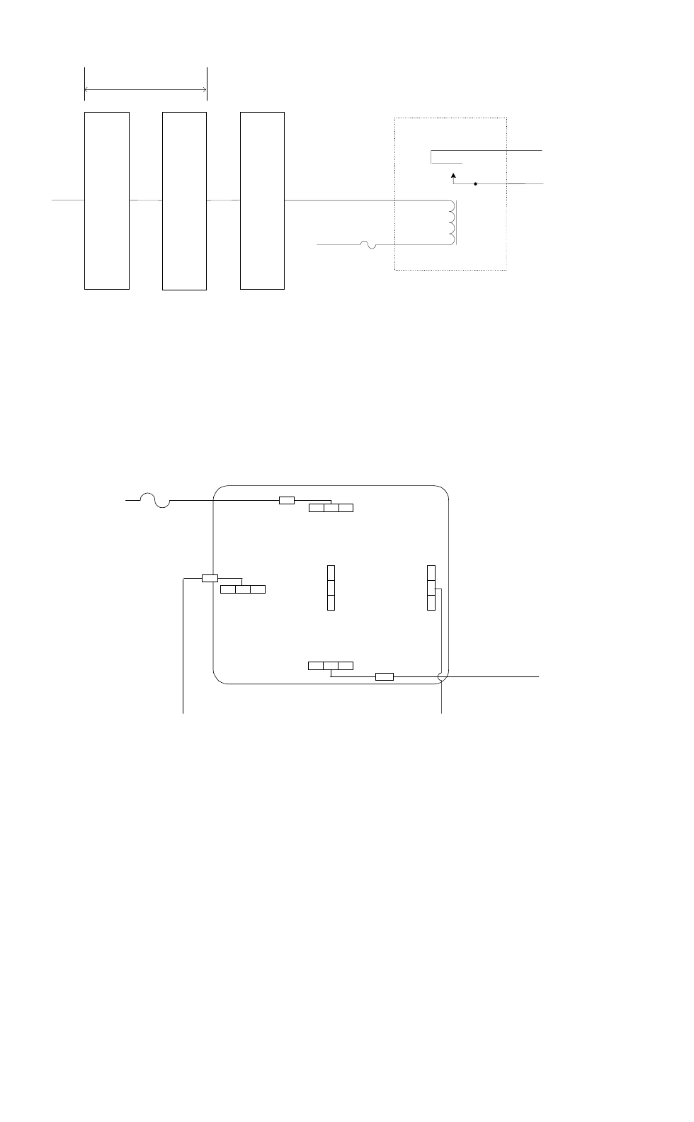
OPTION CABLE
RPM 113 7674/1
PIN 15
ON
18 PIN CONNECTOR
DB-25 CONNECTOR
(FEMALE)
P3 J100
PIN 24
DB-25 CONNECTOR (MALE)
TO BE SUPPLIED BY CUSTOMER
NO
COM To Horn Circuit
To Horn Circuit
RELAY
19A149299P1
30
87
85
FUSE
(1A) 86
BATTERY A+
Figure 13 - External Car Alert
86
87
87a
30
85
TO HORN CIRCUIT
TO RADIO OPTION CABLE
GREEN/WHITE WIRE
FUSE (1A)
BATTERY A+
Figure 14 - External Alarm Relay
30
OPTION CABLE
RPM 113 7674/1
PIN 18
IGNITION
SENSE
18 PIN CONNECTOR
DB-25 CONNECTOR
(FEMALE)
P3 J100
PIN 13
DB-25 CONNECTOR (MALE)
TO BE SUPPLIED BY CUSTOMER
FUSE 1A (OPTIONAL)
VEHICLE FUSE BLOCK
Figure 15 – Ignition Sense Option
Microphone Hanger/Hook Switch Mounting – 344A4678P1
The microphone hanger or Hook Switch should be mounted in a location
convenient to the operator where it will not interfere with the safe operation
of the vehicle or be a hazard to the vehicle passengers. The hanger or hook
switch is designed to mount with the open end of the mounting button slot
pointed upward.
1. Use the hanger or Hook Switch as a template to mark and drill the
mounting holes. Mount the hanger or hook switch with the self-tapping
screws provided.
2. Connect microphone connector to connector on control unit and secure
with captive screw.
NOTE
Do not torque microphone connector screw greater than 2 in-
lb. Alternatively, finger tight plus 1/4 turn is acceptable.
Antenna
Installation instructions for the antenna are packaged with the antenna. The
antenna must be installed in accordance with good engineering practice for
optimum results.

31
Typical Mobile Antenna Installation
A permanent mount-type antenna should be located in the center of the roof
or center of rear deck. Important Note: Rear deck mounting of an
antenna is only applicable when the installation provides at least 25
centimeters (10 inches) between the antenna and occupants of the vehicle.
This distance recommendation is made using a 50% duty cycle.
WARNING
See “Safety Training Information” section at the
beginning of this manual for further information
regarding Specific Absorption Rate (SAR) limits of RF
radiation absorption set by the FCC.
Try to route the cable away from locations where it will be exposed to heat,
sharp edges or mechanical damage, and where it will be out of the way of
the driver, passengers or vehicles mechanics. Wherever possible, existing
holes in the trunk wall, and the channels above or beneath doors and
window columns should be utilized.
Avoid routing the antenna cable near any electronic modules or along side
any vehicle wiring.
Connect the antenna cable to the TNC on the radio, being careful not to
twist the cable.
Typical Desktop Base Station Antenna Installation
For desktop base station configurations, a typical building roof top/tower
installation may be used.
Noise Suppression Kit - Option KMPD1A (19A148539G1)
Refer to the noise suppression kit option installation manual that is included
with this option.

Com-Net Ericsson Critical Radio Systems, Inc.
P.O. Box 2000
Lynchburg, Virginia 24501
1-800-528-7711 (Outside USA, 804-239-3028)
www.com-netericsson.com Printed in U.S.A.