HARRIS TR-0019-E VHF 110W Mobile Radio User Manual 6839 7

HARRIS CORPORATION VHF 110W Mobile Radio 6839 7

Contents

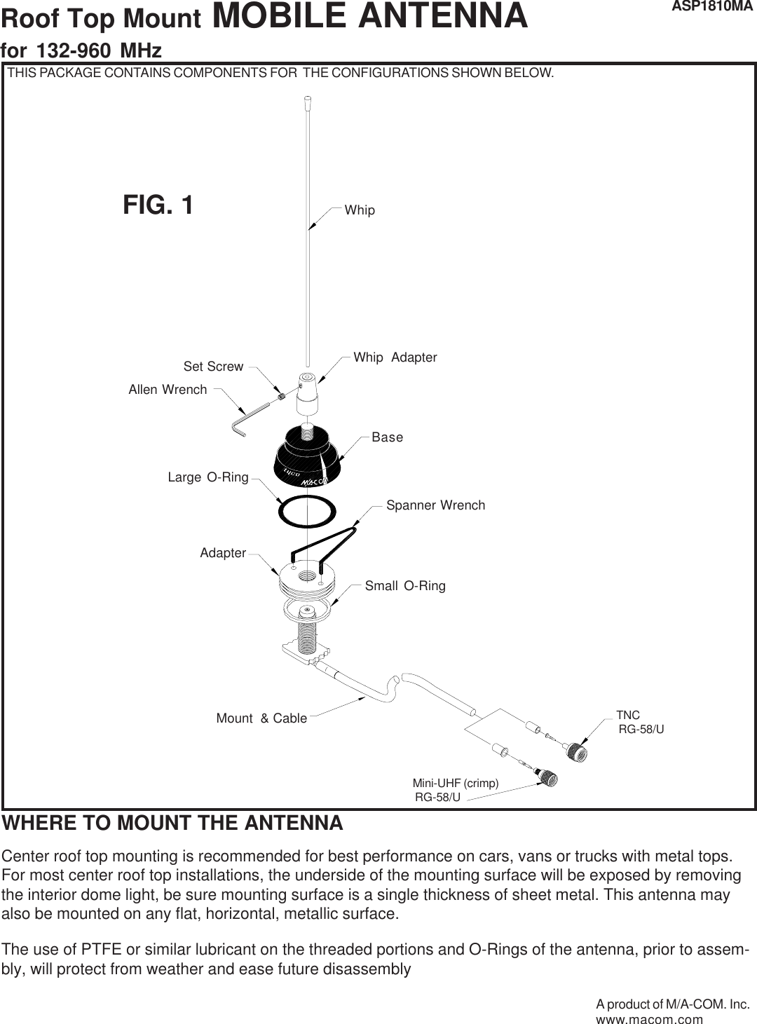
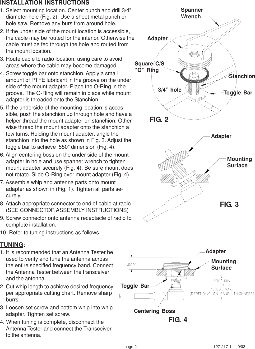
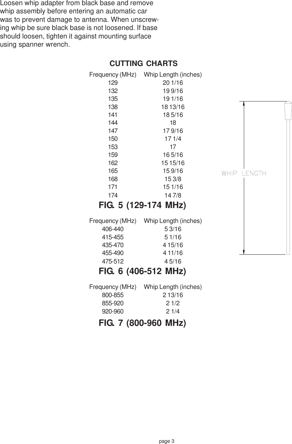
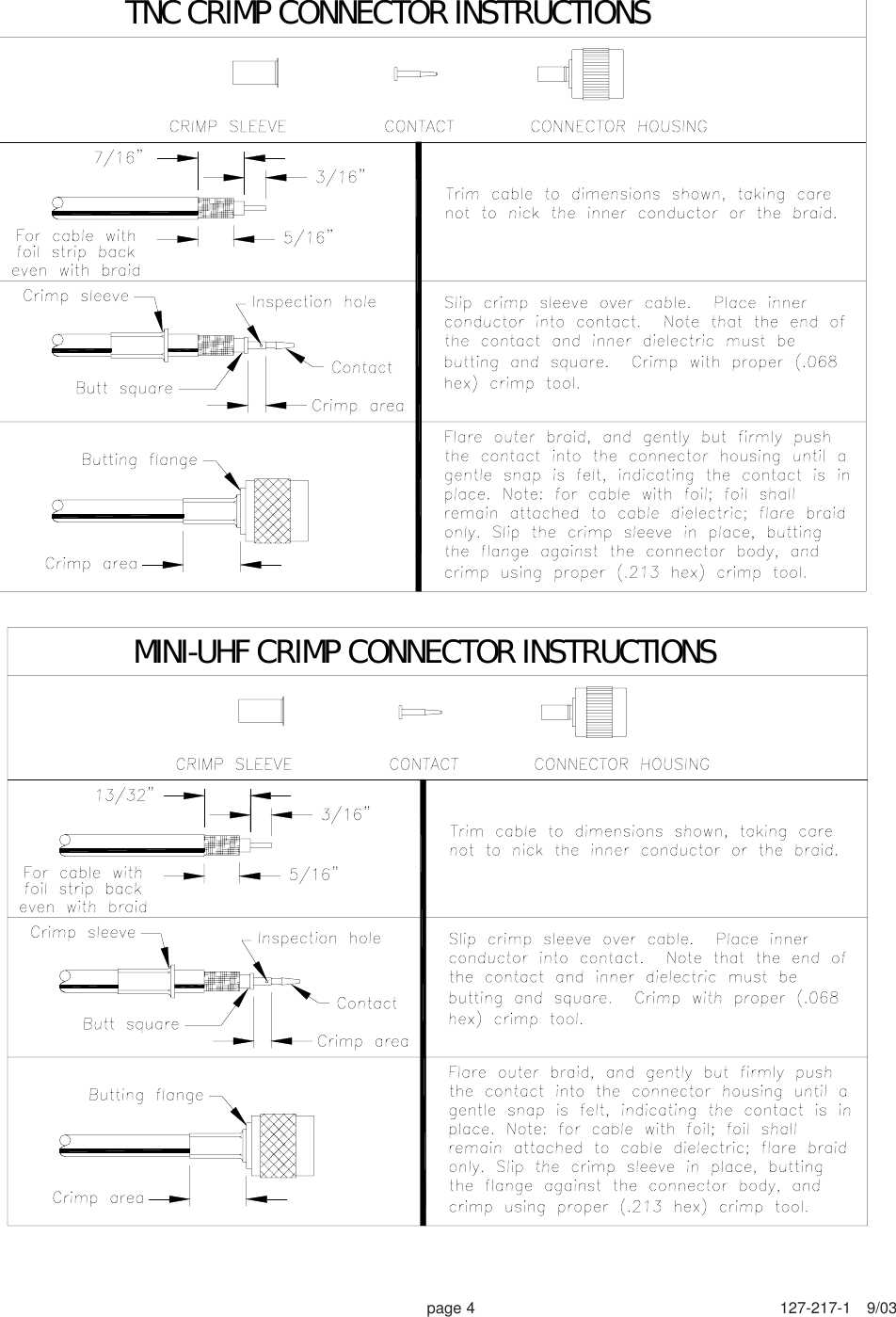
Antenna Install Info

Roof Top Mount MOBILE ANTENNAfor 132-960 MHzWHERE TO MOUNT THE ANTENNACenter roof top mounting is recommended for best performance on cars, vans or trucks with metal tops.For most center roof top installations, the underside of the mounting surface will be exposed by removingthe interior dome light, be sure mounting surface is a single thickness of sheet metal. This antenna mayalso be mounted on any flat, horizontal, metallic surface.The use of PTFE or similar lubricant on the threaded portions and O-Rings of the antenna, prior to assem-bly, will protect from weather and ease future disassemblyFIG. 1ASP1810MAAllen WrenchLarge O-RingBaseSpanner WrenchAdapterWhip  AdapterMount  & CableSmall O-RingWhipSet ScrewMini-UHF (crimp) RG-58/UTNC RG-58/UTHIS PACKAGE CONTAINS COMPONENTS FOR  THE CONFIGURATIONS SHOWN BELOW.A product of M/A-COM. Inc.www.macom.com
page 2 127-217-1     9/03MountingSurfaceToggle BarFIG. 2INSTALLATION INSTRUCTIONS1. Select mounting location. Center punch and drill 3/4”diameter hole (Fig. 2). Use a sheet metal punch orhole saw. Remove any burs from around hole.2. If the under side of the mount location is accessible,the cable may be routed for the interior. Otherwise thecable must be fed through the hole and routed fromthe mount location.3. Route cable to radio location, using care to avoidareas where the cable may become damaged.4. Screw toggle bar onto stanchion. Apply a smallamount of PTFE lubricant in the groove on the underside of the mount adapter. Place the O-Ring in thegroove. The O-Ring will remain in place while mountadapter is threaded onto the Stanchion.5. If the underside of the mounting location is acces-sible, push the stanchion up through hole and have ahelper thread the mount adapter on stanchion. Other-wise thread the mount adapter onto the stanchion afew turns. Holding the mount adapter, angle thestanchion into the hole as shown in Fig. 3. Adjust thetoggle bar to achieve .550” dimension (Fig. 4).6. Align centering boss on the under side of the mountadapter in hole and use spanner wrench to tightenmount adapter securely (Fig. 4). Be sure mount doesnot rotate. Slide O-Ring over mount adapter (Fig. 4).7. Assemble whip and antenna parts onto mountadapter as shown in (Fig, 1). Tighten all parts se-curely.8. Attach appropriate connector to end of cable at radio(SEE CONNECTOR ASSEMBLY INSTRUCTIONS)9. Screw connector onto antenna receptacle of radio tocomplete installation.10. Refer to tuning instructions as follows.TUNING:1. It is recommended that an Antenna Tester beused to verify and tune the antenna acrossthe entire specified frequency band. Connectthe Antenna Tester between the transceiverand the antenna.2. Cut whip length to achieve desired frequencyper appropriate cutting chart. Remove sharpburrs.3. Loosen set screw and bottom whip into whipadapter. Tighten set screw.4. When tuning is complete, disconnect theAntenna Tester and connect the Transceiverto the antenna.StanchionSpannerWrenchAdapterSquare C/S“O” Ring3/4” hole Toggle BarAdapterAdapterMountingSurfaceFIG. 4FIG. 3Centering Boss
page 3CUTTING CHARTSFIG. 7 (800-960 MHz)Loosen whip adapter from black base and removewhip assembly before entering an automatic carwas to prevent damage to antenna. When unscrew-ing whip be sure black base is not loosened. If baseshould loosen, tighten it against mounting surfaceusing spanner wrench.Frequency (MHz) Whip Length (inches)129 20 1/16132 19 9/16135 19 1/16138 18 13/16141 18 5/16144 18147 17 9/16150 17 1/4153 17159 16 5/16162 15 15/16165 15 9/16168 15 3/8171 15 1/16174 14 7/8Frequency (MHz) Whip Length (inches)406-440 5 3/16415-455 5 1/16435-470 4 15/16455-490 4 11/16475-512 4 5/16Frequency (MHz) Whip Length (inches)800-855 2 13/16855-920 2 1/2920-960 2 1/4FIG. 6 (406-512 MHz)FIG. 5 (129-174 MHz)
page 4 127-217-1   9/03TNC CRIMP CONNECTOR INSTRUCTIONSMINI-UHF CRIMP CONNECTOR INSTRUCTIONS

Navigation menu