HARRIS TR-0019-E VHF 110W Mobile Radio User Manual 6839 7
HARRIS CORPORATION VHF 110W Mobile Radio 6839 7
HARRIS >
Contents
- 1. Antenna Install Info
- 2. user manual
- 3. install manual
Antenna Install Info
Roof Top Mount MOBILE ANTENNA
for 132-960 MHz
WHERE TO MOUNT THE ANTENNA
Center roof top mounting is recommended for best performance on cars, vans or trucks with metal tops.
For most center roof top installations, the underside of the mounting surface will be exposed by removing
the interior dome light, be sure mounting surface is a single thickness of sheet metal. This antenna may
also be mounted on any flat, horizontal, metallic surface.
The use of PTFE or similar lubricant on the threaded portions and O-Rings of the antenna, prior to assem-
bly, will protect from weather and ease future disassembly
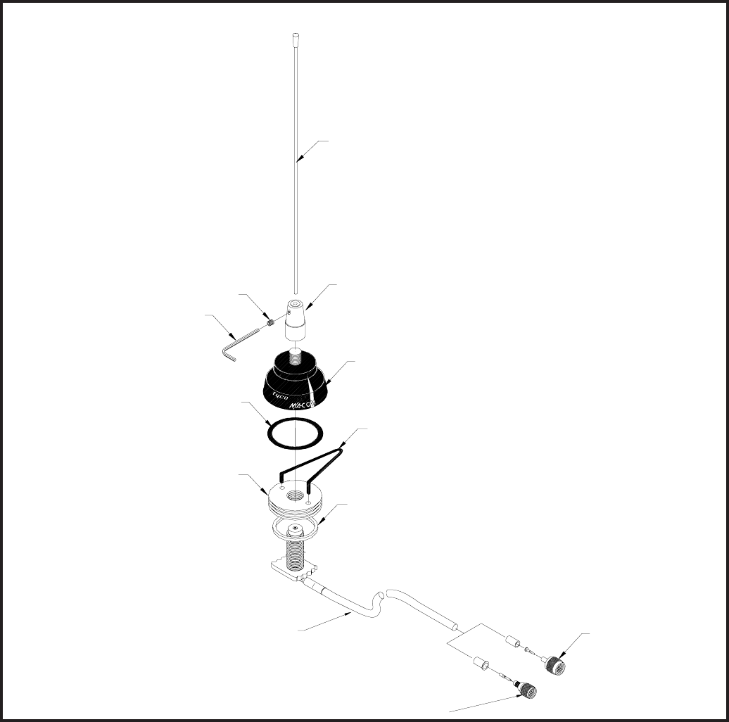
FIG. 1
ASP1810MA
Allen Wrench
Large O-Ring
Base
Spanner Wrench
Adapter
Whip Adapter
Mount & Cable
Small O-Ring
Whip
Set Screw
Mini-UHF (crimp)
RG-58/U
TNC
RG-58/U
THIS PACKAGE CONTAINS COMPONENTS FOR THE CONFIGURATIONS SHOWN BELOW.
A product of M/A-COM. Inc.
www.macom.com
page 2 127-217-1 9/03
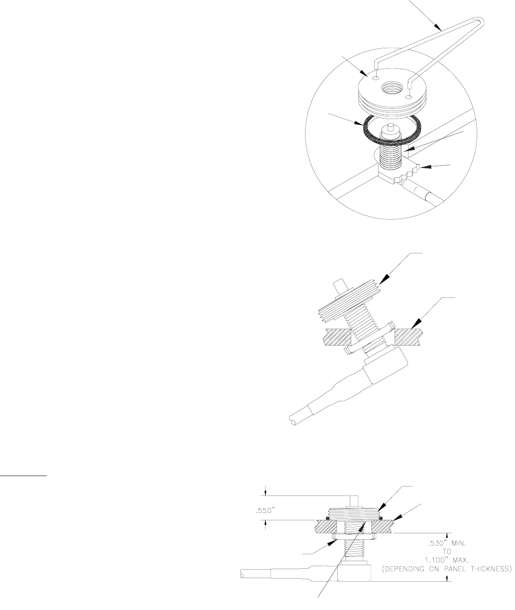
Mounting
Surface
Toggle Bar
FIG. 2
INSTALLATION INSTRUCTIONS
1. Select mounting location. Center punch and drill 3/4”
diameter hole (Fig. 2). Use a sheet metal punch or
hole saw. Remove any burs from around hole.
2. If the under side of the mount location is accessible,
the cable may be routed for the interior. Otherwise the
cable must be fed through the hole and routed from
the mount location.
3. Route cable to radio location, using care to avoid
areas where the cable may become damaged.
4. Screw toggle bar onto stanchion. Apply a small
amount of PTFE lubricant in the groove on the under
side of the mount adapter. Place the O-Ring in the
groove. The O-Ring will remain in place while mount
adapter is threaded onto the Stanchion.
5. If the underside of the mounting location is acces-
sible, push the stanchion up through hole and have a
helper thread the mount adapter on stanchion. Other-
wise thread the mount adapter onto the stanchion a
few turns. Holding the mount adapter, angle the
stanchion into the hole as shown in Fig. 3. Adjust the
toggle bar to achieve .550” dimension (Fig. 4).
6. Align centering boss on the under side of the mount
adapter in hole and use spanner wrench to tighten
mount adapter securely (Fig. 4). Be sure mount does
not rotate. Slide O-Ring over mount adapter (Fig. 4).
7. Assemble whip and antenna parts onto mount
adapter as shown in (Fig, 1). Tighten all parts se-
curely.
8. Attach appropriate connector to end of cable at radio
(SEE CONNECTOR ASSEMBLY INSTRUCTIONS)
9. Screw connector onto antenna receptacle of radio to
complete installation.
10. Refer to tuning instructions as follows.
TUNING:
1. It is recommended that an Antenna Tester be
used to verify and tune the antenna across
the entire specified frequency band. Connect
the Antenna Tester between the transceiver
and the antenna.
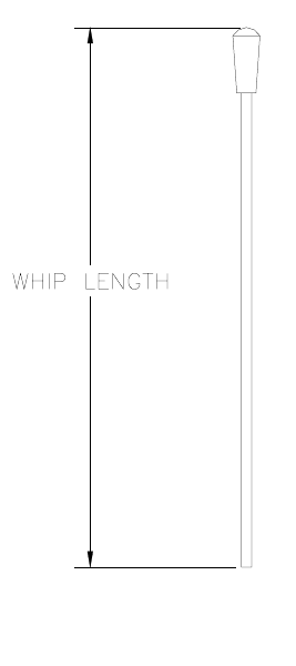
2. Cut whip length to achieve desired frequency
per appropriate cutting chart. Remove sharp
burrs.
3. Loosen set screw and bottom whip into whip
adapter. Tighten set screw.
4. When tuning is complete, disconnect the
Antenna Tester and connect the Transceiver
to the antenna.
Stanchion
Spanner
Wrench
Adapter
Square C/S
“O” Ring
3/4” hole Toggle Bar
Adapter
Adapter
Mounting
Surface
FIG. 4
FIG. 3
Centering Boss
page 3
CUTTING CHARTS
FIG. 7 (800-960 MHz)
Loosen whip adapter from black base and remove
whip assembly before entering an automatic car
was to prevent damage to antenna. When unscrew-
ing whip be sure black base is not loosened. If base
should loosen, tighten it against mounting surface
using spanner wrench.
Frequency (MHz) Whip Length (inches)
129 20 1/16
132 19 9/16
135 19 1/16
138 18 13/16
141 18 5/16
144 18
147 17 9/16
150 17 1/4
153 17
159 16 5/16
162 15 15/16
165 15 9/16
168 15 3/8
171 15 1/16
174 14 7/8
Frequency (MHz) Whip Length (inches)
406-440 5 3/16
415-455 5 1/16
435-470 4 15/16
455-490 4 11/16
475-512 4 5/16
Frequency (MHz) Whip Length (inches)
800-855 2 13/16
855-920 2 1/2
920-960 2 1/4
FIG. 6 (406-512 MHz)
FIG. 5 (129-174 MHz)
page 4 127-217-1 9/03
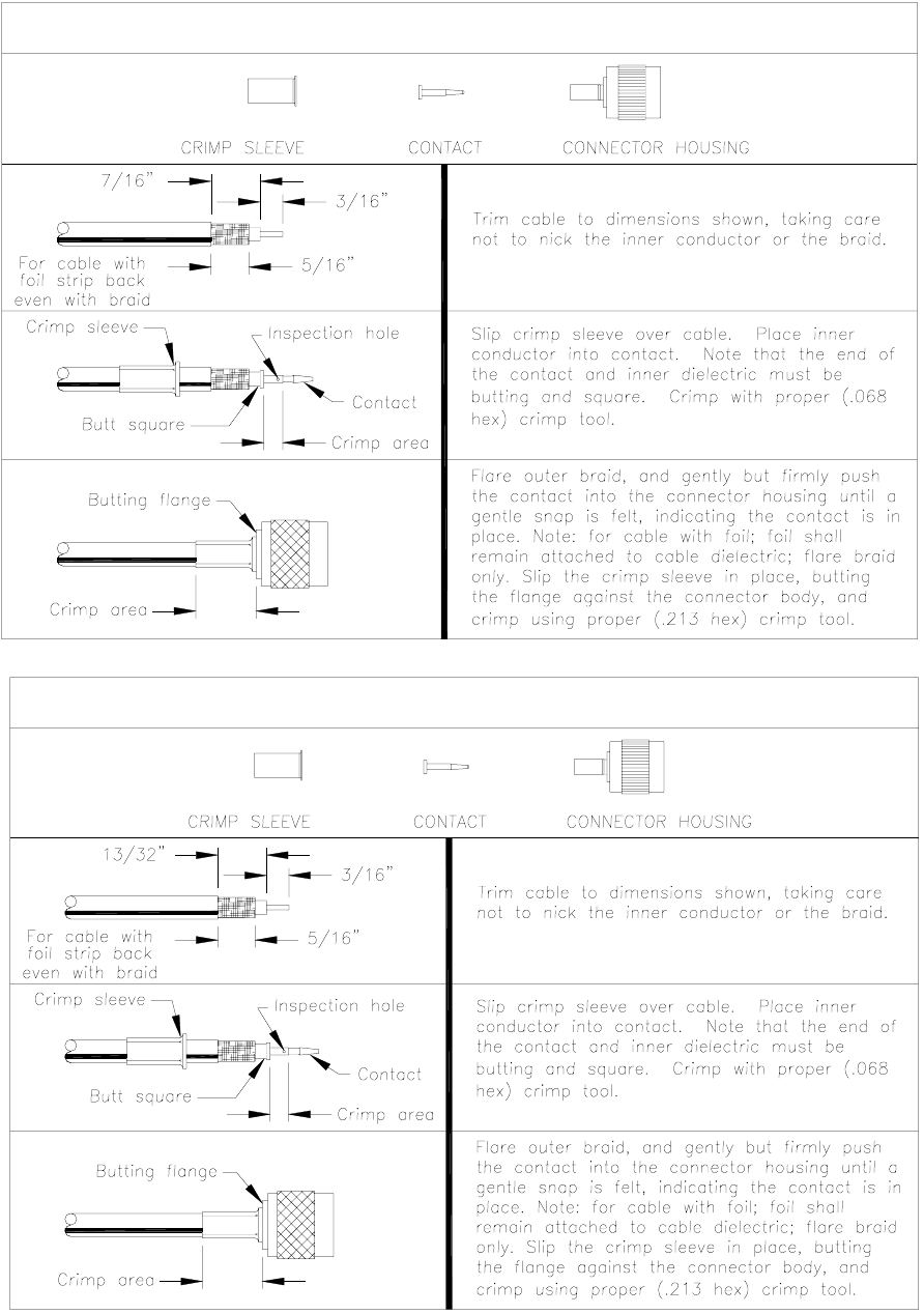
TNC CRIMP CONNECTOR INSTRUCTIONS
MINI-UHF CRIMP CONNECTOR INSTRUCTIONS