HARRIS TR-0022-E M7100 800 MHz Mobile Radio User Manual MM102342V1RevFp1 FCC
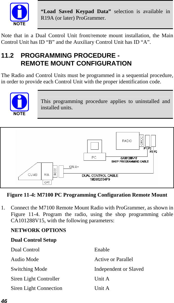
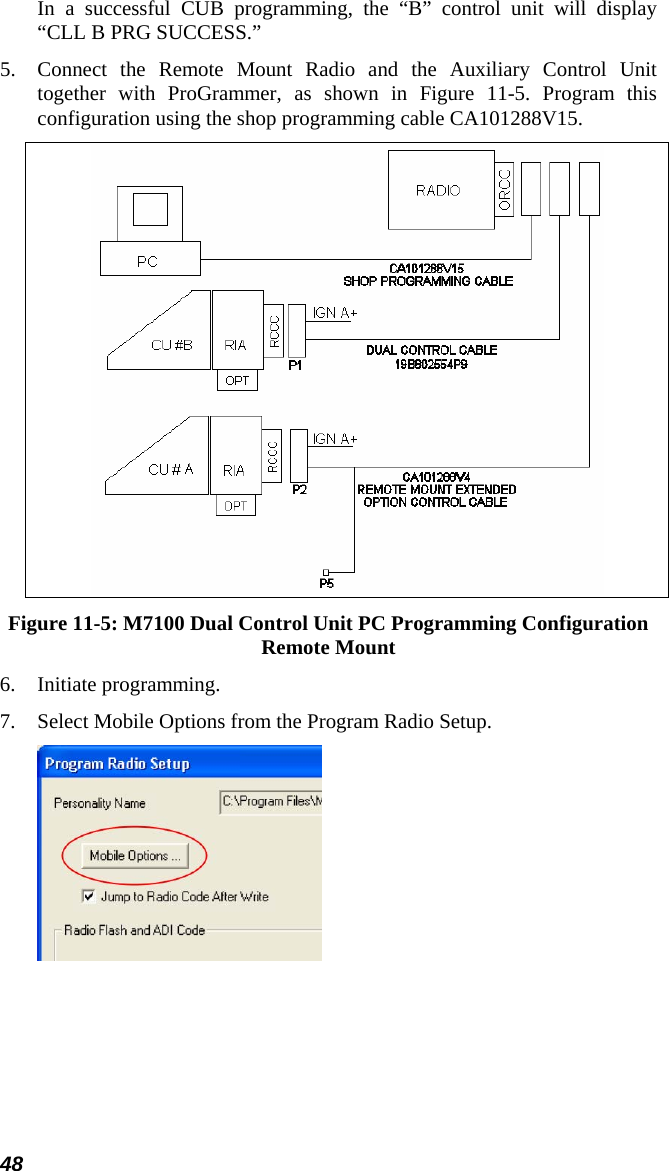
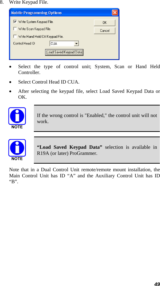
HARRIS CORPORATION M7100 800 MHz Mobile Radio MM102342V1RevFp1 FCC
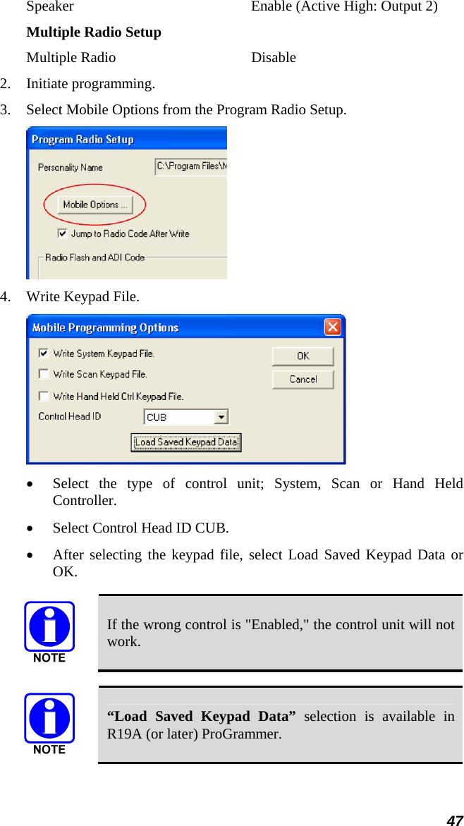
UserManual.wiki
>
HARRIS
>
TR-0022-E User Manual
>
Manual
Contents
1.
Operational Manual
2.
Users Manual Car Revised
3.
Users Manual Motorcycle Revised
4.
Manual
5.
Manual 2
Manual
Navigation menu
Upload a User Manual
Namespaces
Wiki Guide
HTML
PDF
Info
Views
User Manual
Discussion / Help
Navigation


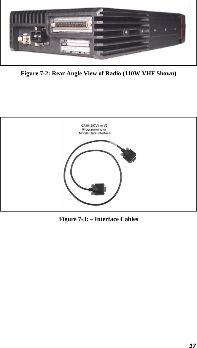
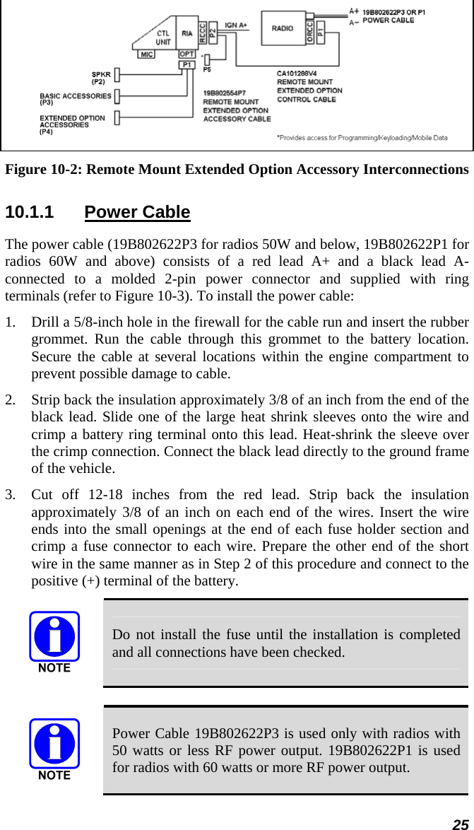
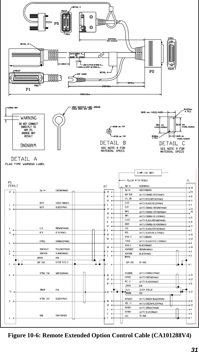
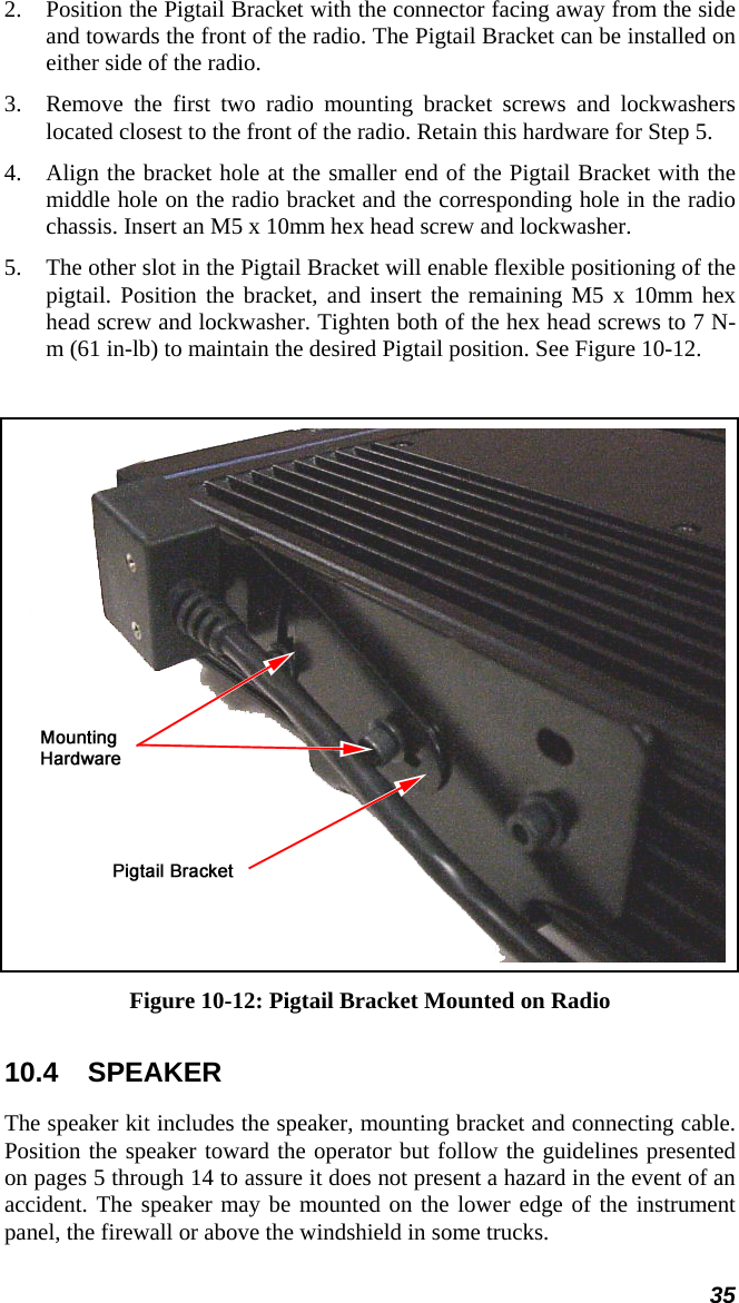
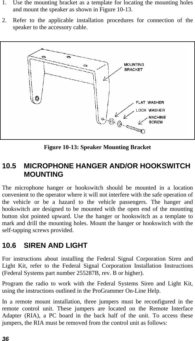
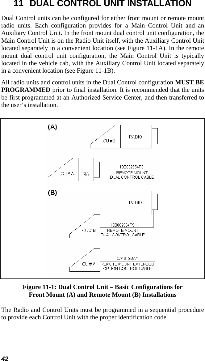
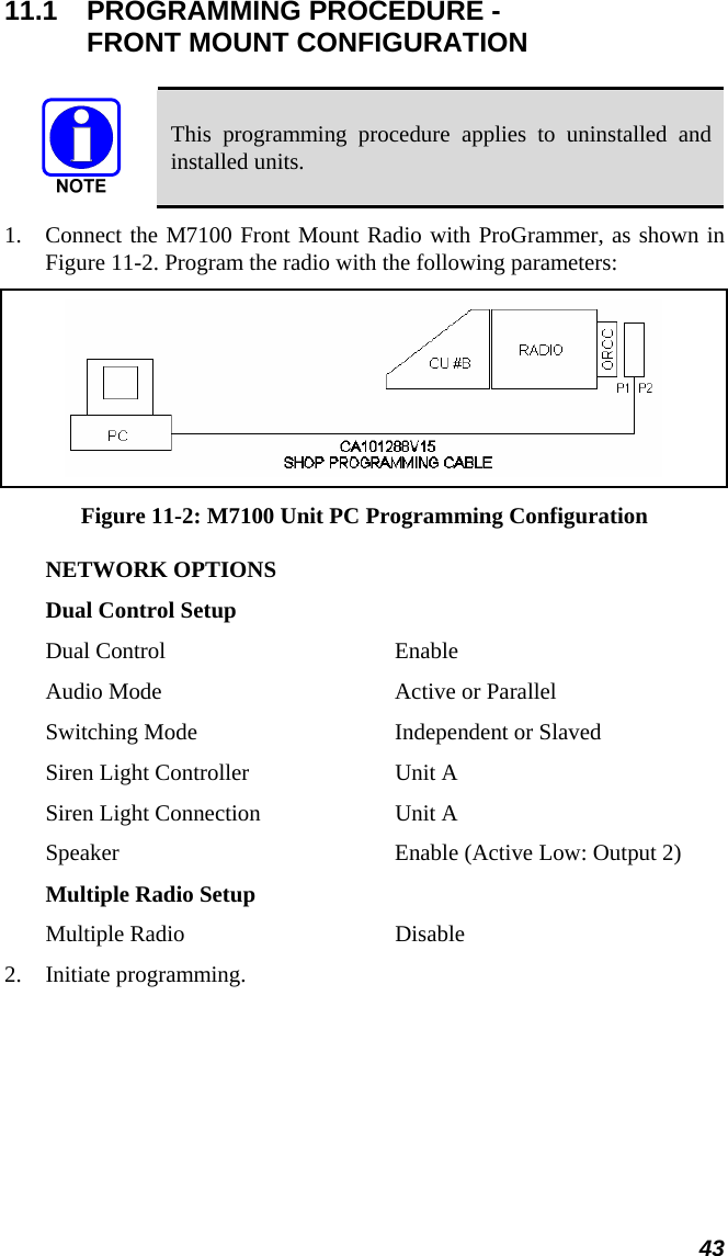
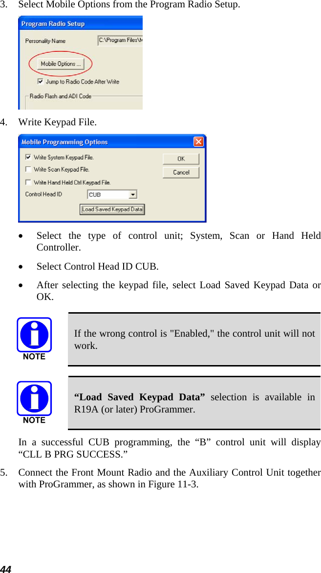
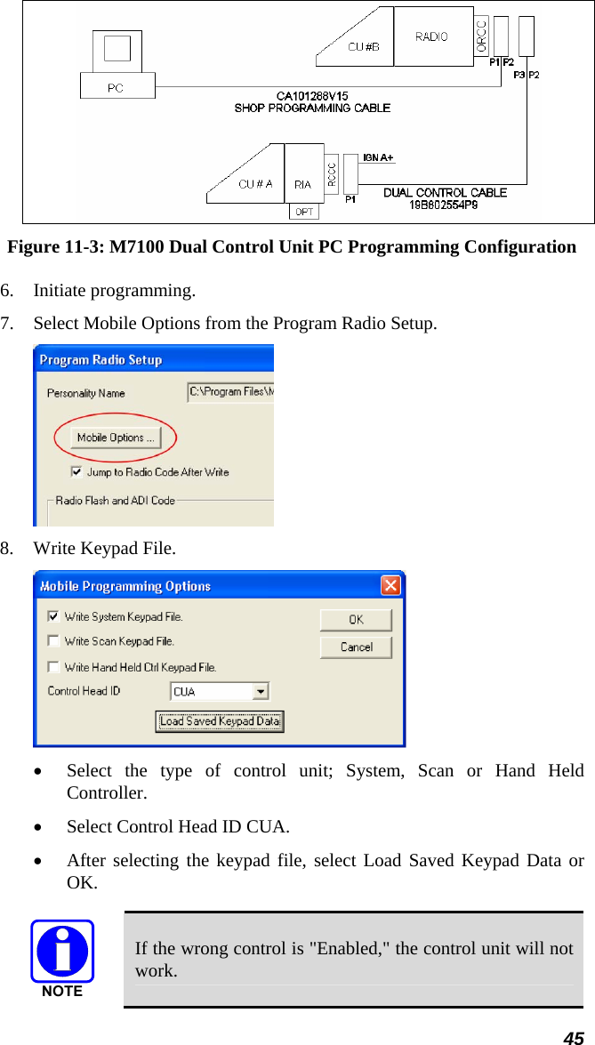
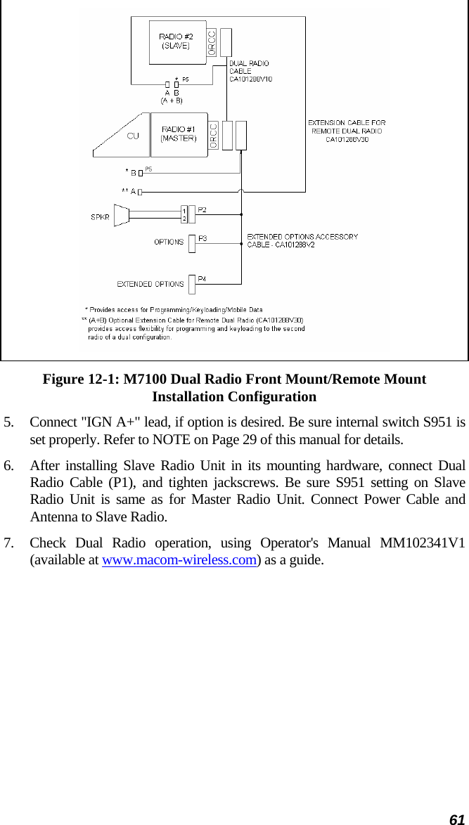
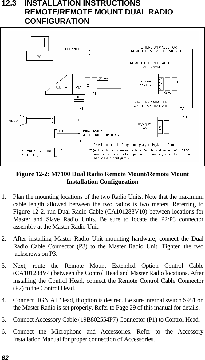
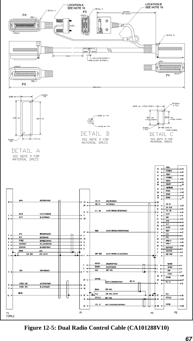
![29 10.1.3 Ignition Sense (All Applications) The radio, as shipped from the factory, has the "ignition sense" feature disabled. As such, the radio will be powered ON or OFF as determined by the front panel ON/OFF/VOLUME control only (assuming A+ and A- are connected). If it is desired to enable the "ignition sense" feature, open the top cover of the radio and remove the shield from logic PWB. Slide switch S951 from position 3-2 to 1-2. Replace shield and top cover. Be sure to apply correct torque to screws holding top cover in place (refer to the appropriate Maintenance Manual). The "Accessory" point should drop to ZERO volts when cranking the engine and return to +12 volts after the engine is started. If a point is chosen that drops to a voltage between zero and +12 volts, the radio might execute a power-up cycle several times during start up. It is recommended that the terminal be measured with a voltmeter to be sure it shuts off (goes to zero volts) during the cranking of the engine. The fuse holder must be attached to the yellow sense lead along with the ring terminal as follows: 1. Cut the yellow sense lead approximately 6-12" from the end that will be connected to the ignition sense point. 2. Strip the insulation from each end of the short lead and from the end of the long lead at least 3/8". 3. Insert the stripped end of the long lead and one end of the short lead into the narrow end of each fuse holder half. 4. Crimp the leads in the fuse holder halves with a crimping tool. 5. Insert the 3-amp fuse into one end of the fuse holder and join the two fuse holder halves firmly together. 6. Attach the ring terminal to the end of the short lead and connect this lead to the ignition "ON" sense point [preferably an "Accessory" point (in the vehicle fuse panel) that is switched on when the vehicle ignition switch is in the ACCESSORY and RUN positions].](https://usermanual.wiki/HARRIS/TR-0022-E.Manual/User-Guide-834933-Page-29.png)