HARRIS TR-0022-E M7100 800 MHz Mobile Radio User Manual MM102343V1RevA
HARRIS CORPORATION M7100 800 MHz Mobile Radio MM102343V1RevA
HARRIS >
Contents
- 1. Operational Manual
- 2. Users Manual Car Revised
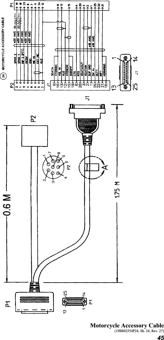
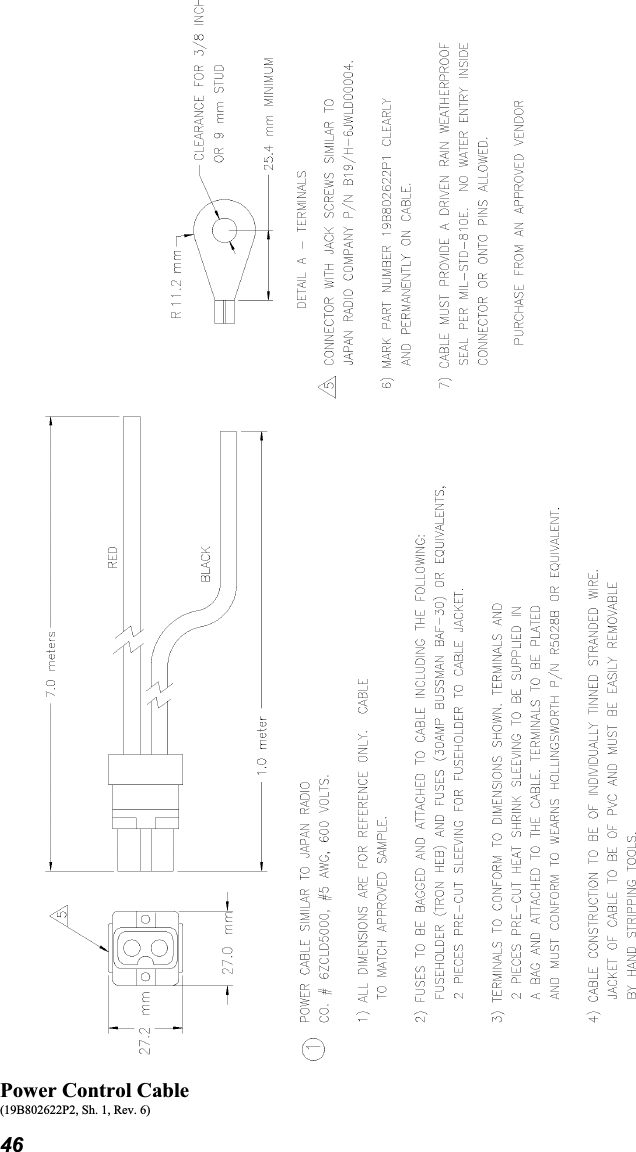
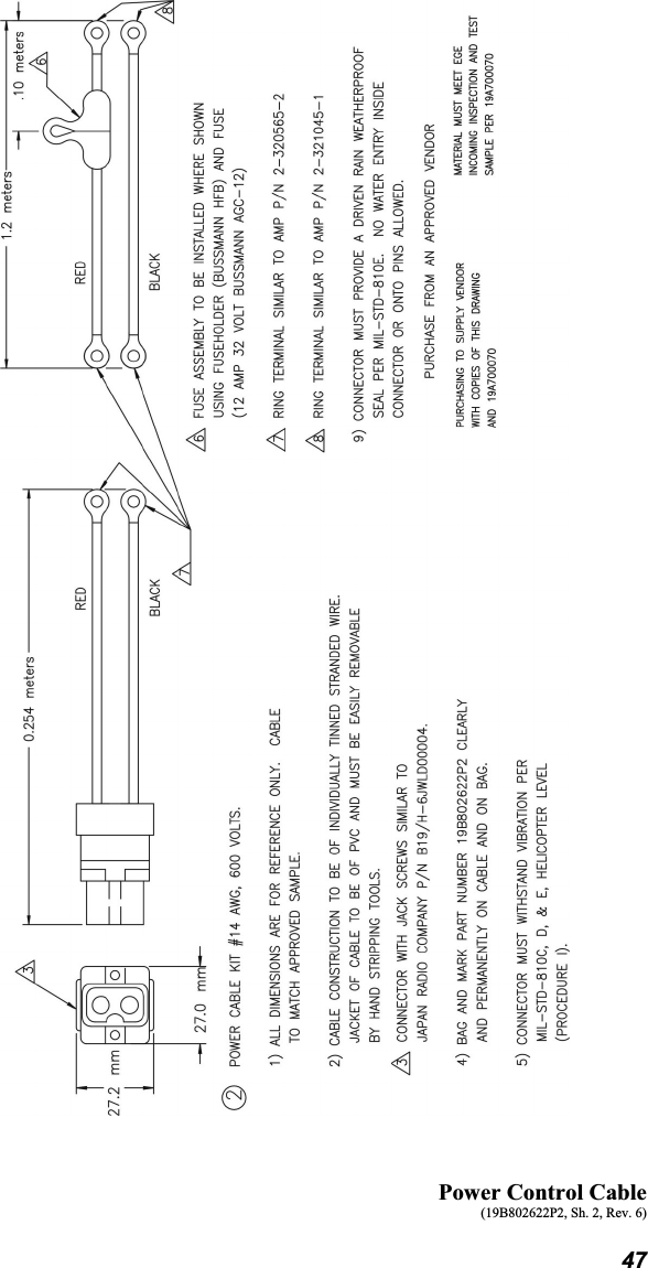
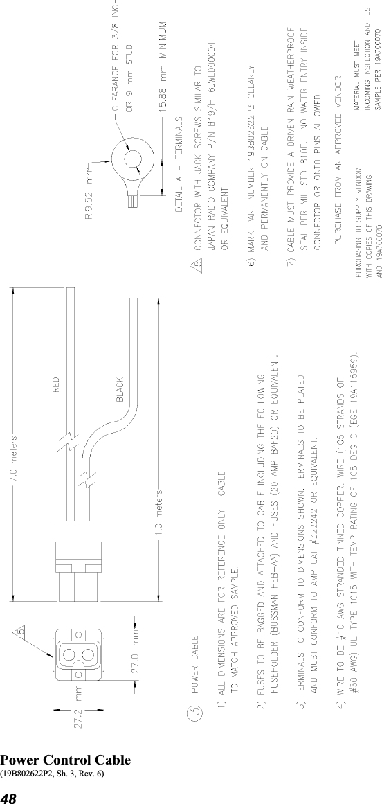
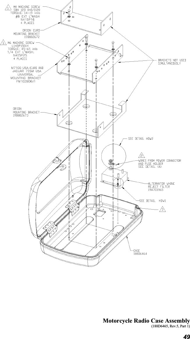
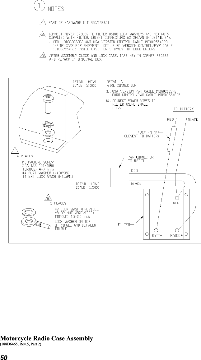
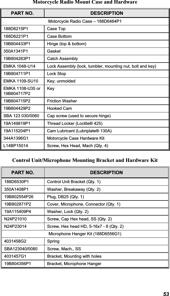
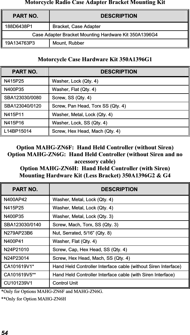
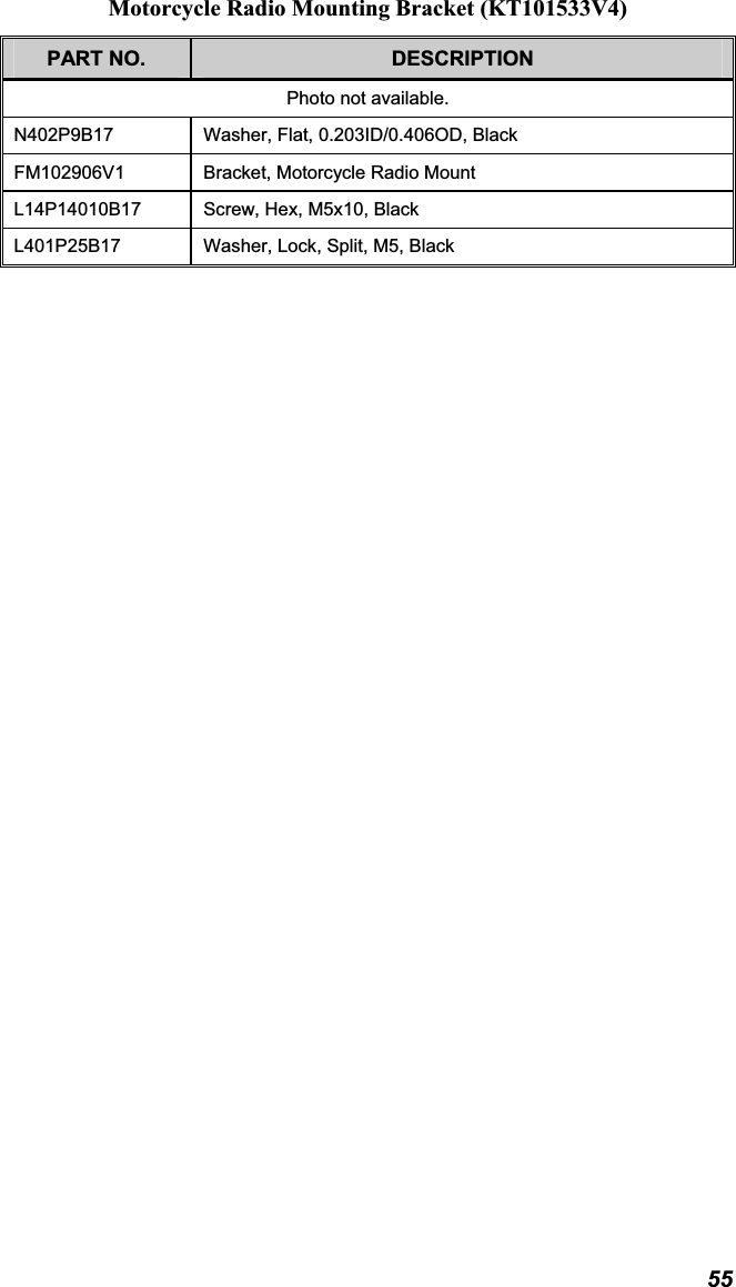
- 3. Users Manual Motorcycle Revised
- 4. Manual
- 5. Manual 2
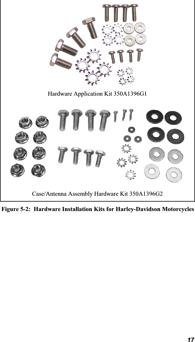
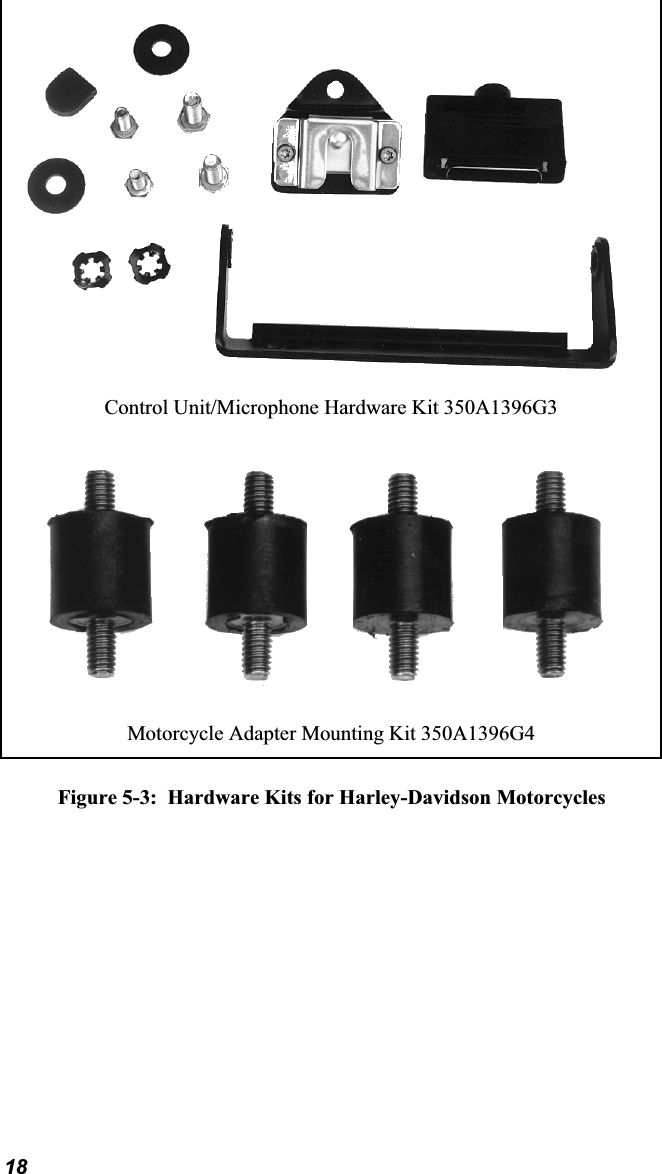
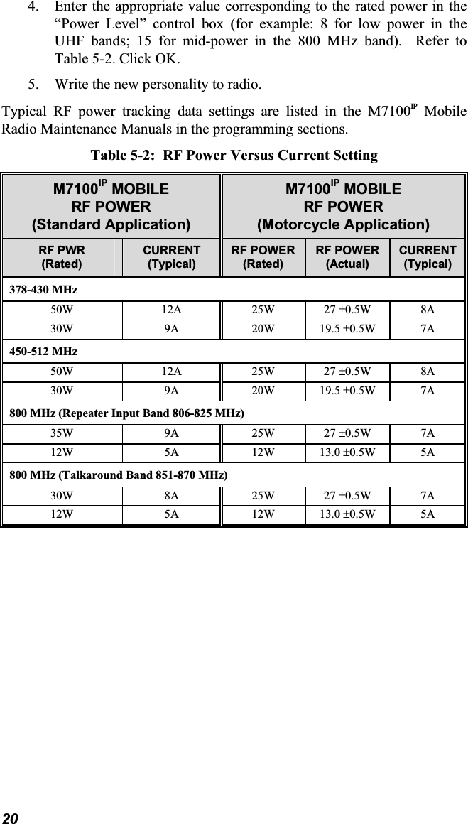
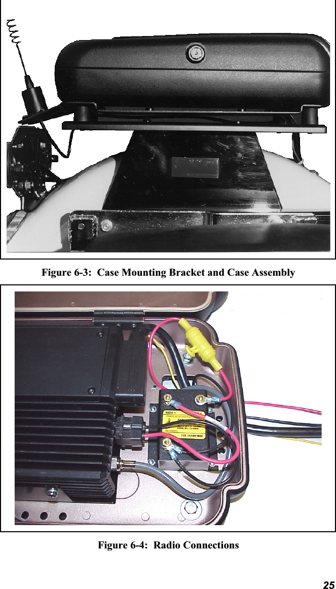
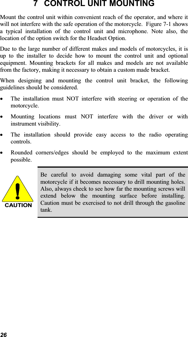
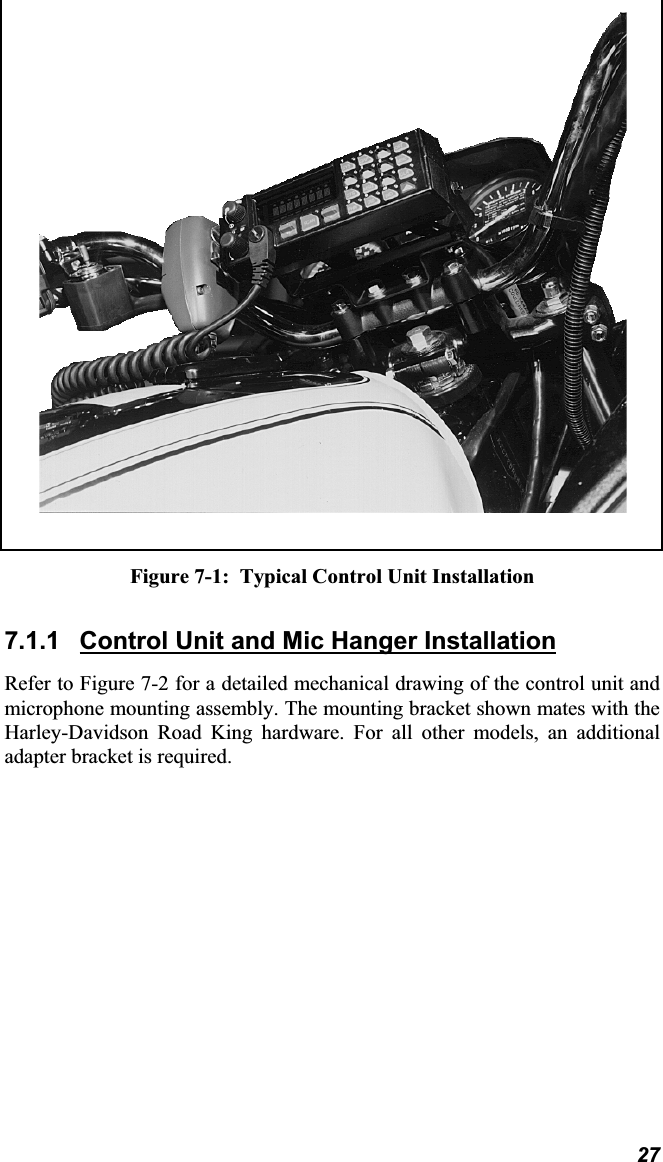
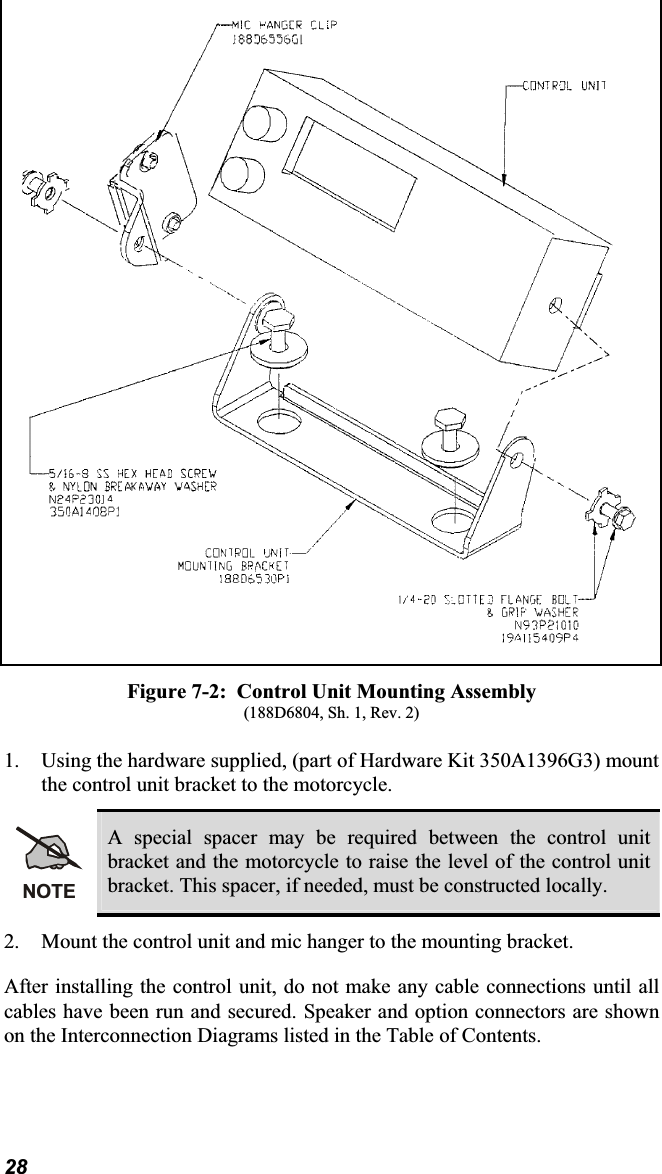
Users Manual Motorcycle Revised