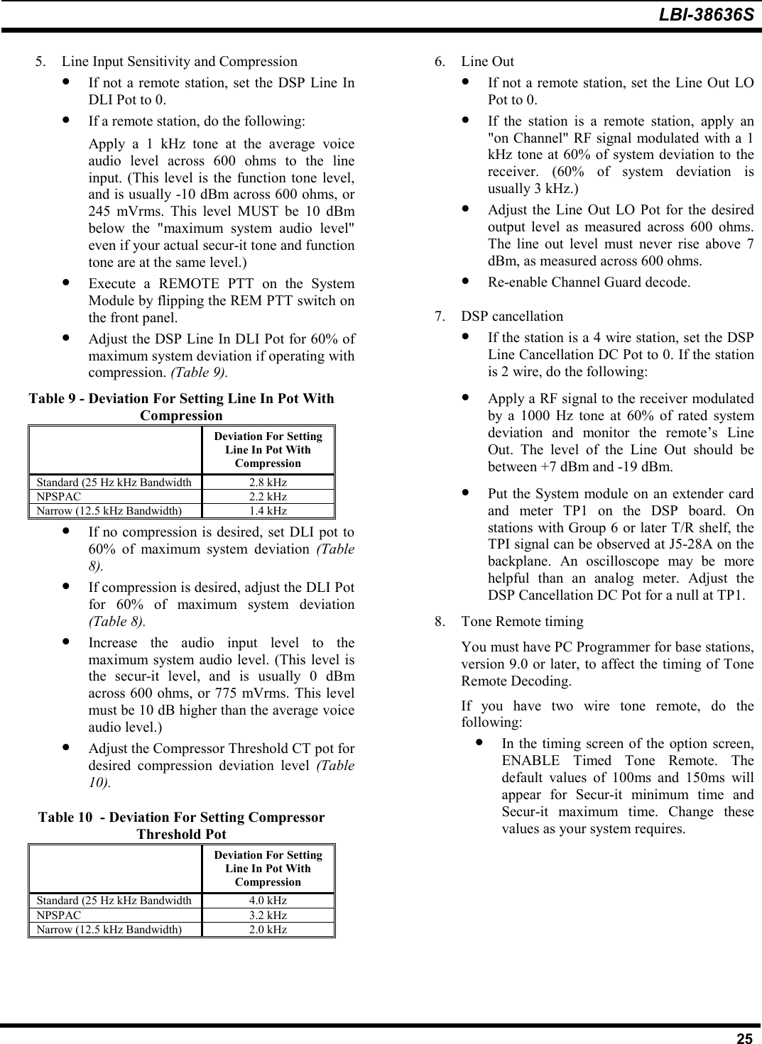
HARRIS TR-0024-E Land Mobile Base Station User Manual Part 90

HARRIS CORPORATION Land Mobile Base Station Part 90

Manual

Rhein Tech Laboratories                                                   Client: M/A COM, Inc. 360 Herndon Parkway                                                                       Model: MastrIII w/Sitepro Base Station Suite 1400                                                                        Standards: FCC Part 90/IC RSS-119 Herndon, VA 20170                                               Report Number: 2003083   http://www.rheintech.com                                                                                 Date: June 6, 2003  48 of 52        APPENDIX G:  MANUAL  Please refer to the following pages.
MASTR IIIConventional Base StationInstallation ManualLBI-38636SPreliminary
LBI-38636S2NOTERepairs to this equipment should be made only by an authorized service technician or facility designated by the supplier.Any repairs, alterations or substitution of recommended parts made by the user to this equipment not approved by themanufacturer could void the user’s authority to operate the equipment in addition to the manufacturer’s warranty.NOTICE!The software contained in this device is copyrighted by M/A-COM Private Radio Systems, Inc. Unpublished rights arereserved under the copyright laws of the United States.This manual is published by M/A-COM Private Radio Systems, Inc., without any warranty. Improvements and changes to this manual necessitated bytypographical errors, inaccuracies of current information, or improvements to programs and/or equipment, may be made  by  M/A-COM Private RadioSystems, Inc., at any time and without notice. Such changes will be incorporated into new editions of this manual. No part of this manual may bereproduced or transmitted in any form or by any means, electronic or mechanical, including photocopying and recording, for any purpose, without theexpress written permission of M/A-COM Private Radio Systems, Inc.Copyright  1992-2002 M/A-COM Private Radio Systems, Inc. All rights reserved.
LBI-38636S3TABLE OF CONTENTSPagePRODUCT SPECIFICATION FOR CE MARKED EQUIPMENT .................................................................................. 4MAXIMUM PERMISSIBLE EXPOSURE (MPE) LIMITS.............................................................................................. 5DETERMINING MPE RADIUS.................................................................................................................................... 5SAFETY TRAINING INFORMATION ............................................................................................................................ 5STATION SPECIFICATIONS (GENERAL) .................................................................................................................... 7PUBLICATIONS INDEX.................................................................................................................................................. 8SAFETY SUMMARY........................................................................................................................................................ 9GROUND THE EQUIPMENT ...................................................................................................................................... 9REPLACEMENT OF PLUG-IN CIRCUIT MODULES ............................................................................................... 9CAUTION .......................................................................................................................................................................... 9ELECTROSTATIC DISCHARGE - SENSITIVE COMPONENTS ............................................................................. 9DO NOT SUBSTITUTE PARTS OR MODIFY PRODUCT ...................................................................................... 10INTRODUCTION ............................................................................................................................................................ 10CABINET..................................................................................................................................................................... 10STATION POWER SUPPLY ...................................................................................................................................... 10TRANSMITTER/RECEIVER SHELF......................................................................................................................... 10TRANSMITTER POWER AMPLIFIER ..................................................................................................................... 10UNPACKING EQUIPMENT........................................................................................................................................... 10SITE PREPARATION AND INSTALLATION.............................................................................................................. 10CABINET INSTALLATION ....................................................................................................................................... 10Single 37-inch Cabinet Installation........................................................................................................................... 10Double Stacked 37-inch Cabinet installation............................................................................................................ 11ELECTRICAL CONNECTIONS................................................................................................................................. 12AC Power ................................................................................................................................................................. 12Microphone............................................................................................................................................................... 12Antenna..................................................................................................................................................................... 12TELEPHONE LINE CHARACTERISTICS................................................................................................................ 12Telephone Lines ....................................................................................................................................................... 12Types Of Voice Grade Lines .................................................................................................................................... 12Tone Remote Control Systems ................................................................................................................................. 14Voting System Considerations.................................................................................................................................. 15Ordering Voice Grade Telephone Lines................................................................................................................... 15Telephone Company Ordering Information.............................................................................................................. 16TELEPHONE LINE INSTALLATION ....................................................................................................................... 16DC Remote Installation ............................................................................................................................................ 16E & M Signaling....................................................................................................................................................... 16Tone Remote Installation.......................................................................................................................................... 17STATION SETUP............................................................................................................................................................ 21SETUP PROCEDURE ................................................................................................................................................. 21ALIGNMENT PROCEDURE...................................................................................................................................... 23AUDIO ROUTING AND ADJUSTMENTS ................................................................................................................... 26TX AUDIO LEVEL ADJUSTMENT .......................................................................................................................... 26REMOTE CONTROLLER TO STATION CONTROL PANEL ADJUSTMENTS ................................................... 30LINE OUT LEVEL ADJUSTMENT ........................................................................................................................... 30LINE IN LEVEL ADJUSTMENT ............................................................................................................................... 30DSP LEVEL ADJUSTMENTS .................................................................................................................................... 30REPEATER PANEL INSTALLATION ...................................................................................................................... 31CSI Model 32 Repeater Panel................................................................................................................................... 31Zetron 38A Repeater Panel....................................................................................................................................... 31ACCESSORIES................................................................................................................................................................ 33
LBI-38636S4TABLE OF CONTENTSPageILLUSTRATIONSFigure 1 - Typical 37-inch MASTR III Stations .................................................................................................................9Figure 2 - 37 Inch Mounting Footprint .............................................................................................................................11Figure 3 - 37-Inch Cabinet................................................................................................................................................11Figure 4 - Stacked 37-Inch Cabinets 11Figure 5 - Microphone Connections .................................................................................................................................12Figure 6 - T/R Shelf Connections .....................................................................................................................................13Figure 7 - Typical E & M Signaling Application..............................................................................................................18Figure 8 - METHOD 1 (Single Metallic Pair) .................................................................................................................. 19Figure 9 - METHOD 2 (Single Metallic, Earth Ground)..................................................................................................19Figure 10 - METHOD 3 (Metallic Control Pair, Audio Pair)...........................................................................................20Figure 11 - METHOD 4 (Full Duplex Metallic TX Pair) .................................................................................................20Figure 12 - Telephone Line Connections..........................................................................................................................21Figure 13 - 3-Wire Adapter...............................................................................................................................................21Figure 14 - Antenna Installation .......................................................................................................................................22Figure 15 - MASTR III System Module Pot Alignment................................................................................................... 24Figure 16 - T/R Shelf Interface Board ..............................................................................................................................27Figure 17 - T/R Shelf Interface Board (Rev. A) ...............................................................................................................28Figure 18 - T/R Shelf Interface Board ( Rev. C)...............................................................................................................29PRODUCT SPECIFICATION FOR CE MARKED EQUIPMENTThe MASTR® III Base Station and Auxiliary Receiver conform to the following Product Specifications.EUROPEAN STANDARDS:Safety: EN60065 (220 VAC applications only)EMC: prETS 300 279 (August 1995)TTD: Not ApplicableSUPPLEMENTARY INFORMATION:The MASTR III Base Station and Auxiliary Receiver may be used in both trunked and conventional applications. Neither theMASTR III Base Station nor the Auxiliary Receiver may be connected to leased lines in Europe without an additional line-barrier protection device.
LBI-38636S5MAXIMUM PERMISSIBLE EXPOSURE (MPE) LIMITSDo not transmit with this basestation and antenna when persons are within the MPE Radius of the antenna. The MPE Radiusis the minimum distance from the antenna axis that ALL persons should maintain in order to avoid RF exposure higher thanthe allowable MPE level set by the FCC.WARNINGFAILURE TO OBSERVE THESE LIMITS MAY ALLOW ALL PERSONS WITHINTHE MPE RADIUS TO EXPERIENCE RF RADIATION ABSORPTION, WHICHEXCEEDS THE FCC MAXIMUM PERMISSIBLE EXPOSURE (MPE) LIMIT. IT ISTHE RESPONSIBILITY OF THE BASESTATION OPERATOR TO ENSURE THATTHE MAXIMUM PERMISSIBLE EXPOSURE LIMITS ARE OBSERVED AT ALLTIMES DURING BASESTATION TRANSMISSION. THE BASESTATIONOPERATOR IS TO ENSURE THAT NO BYSTANDERS COME WITHIN THERADIUS OF THE MAXIMUM PERMISSIBLE EXPOSURE LIMITS SHOWN BELOW.DETERMINING MPE RADIUSTHE MAXIMUM PERMISSIBLE EXPOSURE RADIUS HAS BEEN ESTIMATED TO BE A RADIUS OF 24 FEETMAXIMUM ASSUMING THE HIGHEST EFFECTIVE RADIATED POWER (ERP) ALLOWABLE UNDER FCCRULES FOR BASESTATION ANTENNA INSTALLATIONS. THIS ESTIMATE IS MADE ASSUMINGMAXIMUM ALLOWABLE ERP LEVEL BY THE FCC AND 100 PERCENT DUTY CYCLE. THE MPECALCULATIONS WERE MADE ASSUMING WORST CASE IN EACH BAND WITH RESPECT TOFREQUENCY, ERP AND LIMIT. THE MAXIMUM ALLOWABLE ERP WAS DETERMINED FROM THEAPPLICABLE PART 90 RULES REGARDING POWER LIMITATION ( 90.205, 90.309, 90.635 ). THE LIMITUSED WAS FOR UNCONTROLLED EXPOSURE. THE FORMULA USED WAS DERIVED FROM OET 65,SECTION 2, EQUATION 4.SAFETY TRAINING INFORMATIONWARNINGYOUR M/A-COM MASTR III BASESTATION GENERATES RFELECTROMAGNETIC ENERGY DURING TRANSMIT MODE. THIS BASESTATIONIS DESIGNED FOR AND CLASSIFIED AS “OCCUPATIONAL USE ONLY”MEANING IT MUST BE USED ONLY IN THE COURSE OF EMPLOYMENT BYINDIVIDUALS AWARE OF THE HAZARDS AND THE WAYS TO MINIMIZE SUCHHAZARDS. THIS BASESTATION IS NOT INTENDED FOR USE BY THE “GENERALPOPULATION” IN AN UNCONTROLLED ENVIRONMENT. IT IS THERESPONSIBILITY OF THE BASESTATION OPERATOR TO ENSURE THAT THEMAXIMUM PERMISSIBLE EXPOSURE LIMITS DETERMINED IN THE PREVIOUSSECTION ARE OBSERVED AT ALL TIMES DURING TRANSMISSION. THEBASESTATION OPERATOR IS TO ENSURE THAT NO BYSTANDERS COMEWITHIN THE RADIUS OF THE MAXIMUM PERMISSIBLE EXPOSURE LIMITS.This basestation has been examined and complies with the FCC RF exposure limits when persons are beyond the MPE radiusof the antenna. In addition, your M/A-COM basestation complies with the following Standards and Guidelines with regard toRF energy and electromagnetic energy levels and evaluation of such levels for exposure to humans:• FCC OET Bulletin 65 Edition 97-01 Supplement C, Evaluating Compliance with FCC Guidelines for HumanExposure to Radio Frequency Electromagnetic Fields.• American National Standards Institute (C95.1 – 1992), IEEE Standard for Safety Levels with Respect to HumanExposure to Radio Frequency Electromagnetic Fields, 3 kHz to 300 GHz.
LBI-38636S6• American National Standards Institute (C95.3 – 1992), IEEE Recommended Practice for the Measurement ofPotentially Hazardous Electromagnetic Fields – RF and Microwave.CAUTIONTO ENSURE THAT YOUR EXPOSURE TO RF ELECTROMAGNETIC ENERGY ISWITHIN THE FCC ALLOWABLE LIMITS FOR OCCUPATIONAL USE, ALWAYSADHERE TO THE FOLLOWING GUIDELINES:DO NOT operate the basestation with an antenna that would cause an ERP in excess of thatallowable by the FCC.
LBI-38636S7STATION SPECIFICATIONS(GENERAL)CABINET 37-INCH 69-INCHHeight 37.0 inches 69.1 inchesWidth  21.5 inches 23.1 inchesDepth 18.25 inches 21.0 inchesWeight (note 1) 150 lbs (68 kg)Rack Units (RU) (note 2)Cabinet capacity  17 RU 33 RURadio  8 RU  8 RUDuty Cycle (EIA)  Tx and Rx at 100%(continuous)Operating Temperature -30°C to +60°CHumidity (EIA) 90% at 50°CAC Input Power  5 Amps at 120 Vac (-20%) 60 Hzor3 Amps at 230 Vac (-15%) 50 HzDC Input Power 33 Amps at 13.8 Vdc (transmit, full power)25 Amps at 13.8 Vdc (transmit, half power)1.6 Amps at 13.8 Vdc (receive only, standBy)1.75 Amps at 13.8 Vdc (receive only, 1 watt atservice speaker)Service Speaker  1 watt at 8 ohmsService Microphone DynamicNotes:1. Typical station consists of:a. One T/R Shelf with plug-in modules.b. One Power Amplifier.c. One power supply unit.d. One cabinet with doors.2. One rack unit equals 1.75 inches.INTERFACELine InterfaceLine Interface  2-wire or 4-wire (programmable)Line Cancellation  (2-wire) 20 dB amplitude only (programmable)Line Input (line to transmitter)Line Terminating Impedance 600 ohms (2-wire or 4-wire)Line Input Level (adjustable) -20 dBm to +11 dBmFrequency Response 300 Hz to 3000 HzLine Input (receiver to line)Line Terminating Impedance 600 ohms (2-wire or 4-wire)Line Output Level (adjustable) zero output to +11 dBm (ref at 1 kHz)Frequency Response 300 Hz to 3000 Hz, ±1 dBRemote Control (Tone)Control Tones (Hz) 1050, 1150, 1250, 1350, 1450, 1550, 1650, 1750,1850, 1950, 2050, & 2175Secur-it 2175 HzFunction ProgrammableHold 2175 HzDC Remote ControlControl currents -2.5 mA, ±6.0 mA, ±11.0 mA
LBI-38636S8PUBLICATIONS INDEXMASTR III BASE STATION Systems Combination Package ..............................................................LBI-38775T/R Shelf..........................................................................................................................................LBI-38637System Module ................................................................................................................................LBI-38764LBI-39176Power Module..................................................................................................................................LBI-38752MASTR III PC Programmer......................................................................................................................TQ-3353MASTR III Installation Manual..............................................................................................................LBI-38636RF Module Test Fixture..........................................................................................................................LBI-38805MASTR III Utility Handset ....................................................................................................................LBI-38599RF Package: High Band (136 - 174 MHz)..............................................................................................LBI-38754Transmit Synthesizer Module ..........................................................................................................LBI-38640Receive Synthesizer Module............................................................................................................LBI-38641Receiver Front End Module.............................................................................................................LBI-38642IF Module ........................................................................................................................................LBI-38643LBI-39123Power Amplifier ..............................................................................................................................LBI-38531Duplexer ..........................................................................................................................................LBI-38763RF Package: UHF (380 - 512 MHz) .......................................................................................................LBI-38675Transmit Synthesizer Module ..........................................................................................................LBI-38671Receive Synthesizer Module............................................................................................................LBI-38672Receiver Front End Module.............................................................................................................LBI-38673LBI-39129IF Module ........................................................................................................................................LBI-38643LBI-39123Power Amplifier ..............................................................................................................................LBI-38674Duplexer ..........................................................................................................................................LBI-38763RF Package: 800 MHz............................................................................................................................LBI-39025Transmit Synthesizer Module ..........................................................................................................LBI-39026Receive Synthesizer Module............................................................................................................LBI-39027Receive RF Module .........................................................................................................................LBI-39028IF Module ........................................................................................................................................LBI-39029Power Amplifier  ............................................................................................................... (100 W)LBI-39030AE/LZB 119 3521/1Power Amplifier ................................................................................................................ (110 W)LBI-39127Power Supply...................................................................................................................................LBI-38550Power Supply (800 MHz) .......................................................................................................................LBI-38551Emergency Power (Battery Charger)......................................................................................................LBI-38625Auxiliary Receiver VHF.........................................................................................................................LBI-39114UHF .................................................................................................................................................LBI-39115800 ...................................................................................................................................................LBI-39113Voice Guard System Manual ..................................................................................................................LBI-31600Voice Guard/Aegis .................................................................................................................................LBI-38879LBI-38880LBI-38881Adaptive Multipath Pop Filter (AMPF)...................................................................................AE/LZT 123 3244/1Antenna Systems.....................................................................................................................................LBI-38983NOTE: Indented maintenance manuals are included with the header (cover) maintenance manual.
LBI-38636S9Figure 1 - Typical 37-inch MASTR III StationsSAFETY SUMMARYThe following general safety precautions must beobserved during all phases of operation, service, andrepair of this product. Failure to comply with theseprecautions or with specific warnings elsewhere in thismanual violates safety standards of design, manufacture,and intended use of the product. M/A-COM assumes noliability for the customer’s failure to comply with thesestandards.GROUND THE EQUIPMENTTo minimize shock hazard, the station equipmentcabinet must be connected to an electrical ground. Theequipment supplied is equipped with a three-conductorAC power cord. The power cord must be plugged into anapproved three-contact electrical outlet with thegrounding wire firmly connected to an electrical ground(safety ground) at the power outlet. The power cord meetsInternational Electrotechnical Commission (IEC) safetystandards.REPLACEMENT OF PLUG-IN CIRCUITMODULESComponent or module replacement and internaladjustments must be made by qualified maintenancetechnicians.CAUTIONDo Not replace components or modules withpower applied.ELECTROSTATIC DISCHARGE -SENSITIVE COMPONENTSThis station contains CMOS and other circuitcomponents, which may be damaged by electrostaticdischarge. Proper precaution must be taken whenhandling circuit modules. As a minimum, grounded wriststraps should be used at all times when handling circuitmodules.
LBI-38636S10DO NOT SUBSTITUTE PARTS ORMODIFY PRODUCTBecause of the danger of introducing additionalhazards, do not install substitute parts or perform anyunauthorized modifications to the product.INTRODUCTIONThis manual describes the installation andconnections for a typical MASTR III station combination.Information provided includes suggested locations andinstallation of equipment and hardware, interconnectionand assembly diagrams, alignment instructions, andtroubleshooting suggestions.The MASTR III cabinet normally includes theTransmitter/Receiver Shelf, the Transmitter PowerAmplifier, and a Station Power Supply. The assembliesare mounted in a 37-inch cabinet. Optional 69- inch ortwo stacked 37-inch cabinets are available.CABINETThe system is contained in a 37-inch cabinet withimproved ventilation for greater reliability. The cabinetcan also house optional equipment such as a Duplexer,Charger, Gell Cell batteries, or Auxiliary Receiver.STATION POWER SUPPLYThe Station Power Supply provides all necessarypower to run the station. It provides 13.2 volts at 33 ampsto the station from an AC source. The source voltagedepends on the particular area and power sourcesavailable. The power supply is normally mounted beneaththe T/R Shelf.TRANSMITTER/RECEIVER SHELFThe MASTR III Transmitter/Receiver (T/R) Shelfcontains the station control electronics for dc/tone remote,re-mote/repeater, or repeater only applications. Thestation control electronics consists of a Backplane board,Power Module, System Module, and an Interface Board.The back-plane also connects the RF Section whichconsists of the Receiver Synthesizer Module, First IFModule, Second IF Module, and the Transmit SynthesizerModule.TRANSMITTER POWER AMPLIFIERThe Transmitter Power Amplifier is mounted directlybehind the T/R Shelf. Cabling from the output of PowerAmplifier will depend on the system configuration.UNPACKING EQUIPMENTUnpack the station and carefully inspect each item. Ifany damage has occurred to the equipment duringshipment, immediately file a claim with the freightcarrier. AC power adequate to meet system requirements,environmental control, and digital or voice grade phonelines must be available at the site prior to installation.SITE PREPARATION ANDINSTALLATIONCABINET INSTALLATIONThe MASTR III station cabinet is designed forservicing from the front. However, the system may alsobe serviced from the rear when adequate space isavailable. The cabinet should be mounted on a level, solidsurface.If rear servicing is desired, cabinets should be setupwith a minimum of 24-inches of clearance in the rear andbetween cabinets or wall to permit ventilation and roomfor the service-man to move between and behind thecabinets.If space is at a premium or if servicing is to be madefrom the front only, then cabinets should be setup with aminimum of 18-inches of clearance in the rear and 12-inches between cabinets to permit ventilation. However,access to the rear of the cabinets may still be necessary inorder to install or repair antenna or power cables.Single and double stacked 37-inch cabinets must besecurely anchored to the floor according to the footprintshown in Figure 2 and following single or double stackedinstallation instructions.Single 37-inch Cabinet InstallationThe station provides for front and rear door servicingor front door only servicing in tight space situations. Thefront and rear of the station must be kept clear ofobstructions so that the serviceman can easily remove thefront and rear doors for servicing. Also, the front and rearair vent louvers and rear cable outlets must be free ofobstructions.
LBI-38636S11Figure 2 - 37 Inch Mounting FootprintFigure 3 - 37-Inch CabinetUsing the four holes are provided in the bottomsurface of the cabinet, the cabinet must be securely boltedto the floor with 1/2" bolts and anchors as shown inFigures 2 and 3. It will be necessary to remove the frontand rear door covers and some internal components toallow access to the bottom securing holes.Double Stacked 37-inch Cabinet installationFor limited floor space situations, two 37-inchMASTR III cabinets may be stacked one upon the other.This requires that the bottom cabinet be securely bolted tothe floor surface and the top cabinet securely bolted to thetop surface of the bottom cabinet, as shown in Figure 4.Ensure first that the floor is strong enough to supportthe weight of the two cabinet configuration and thatadequate ceiling height is available. Ensure the front andrear, of the station cabinets are clear of obstructions soserviceman can easily remove the front and rear doors forservicing. Also, the front and rear air louvers and rearcable outlets must be free of obstructions. Leave aminimum of 12-inches of space on each side of thecabinets to avoid obstructing the louver air vents. Withthe bottom cabinet in position, secure it to the floor asshown in Figure 2 with 1/2-inch bolts and anchors.Remove the four plastic plugs in the top surface of thebottom cabinet (by squeezing the plastic retaining barbstogether from the inside of the cabinet and pushing theplug up and out).Position the top cabinet on the bottom cabinet. Alignthe fixing holes and bolt the cabinets securely togetherusing 1/2 inch bolts, washers, and locknuts (supplied inhardware kit 344A3450G7) as shown in Figure 4.It will be necessary to remove the front and rearcovers and some internal components to allow access tothe top and bottom securing holes.Figure 4 - Stacked 37-Inch Cabinets
LBI-38636S12ELECTRICAL CONNECTIONSAC PowerThe station will be received with the power cordbundled and stored in the bottom of the cabinet. Removethe twist tie from the AC power cord, unravel and feed thecord through one of the rear cable holes. It may be helpfulto remove the grommet from the hole before passing thecord through and reinstalling it afterwards.A separate 15 to 20 Ampere, 120 Vac, 60 Hertzelectrical circuit should be provided for the station. A 120volt grounded AC outlet for the station should be locatedwithin six feet of the lower rear of the cabinet. The powercord for the 120 Vac Power Supply comes with agrounded 120 Vac molded plug attached. Check theelectrical code to ensure the power outlet complies withlocal ordinances.If a 240 Vac, 60 Hz source is used for the station, anexternal step-down transformer (similar to 19C307148P1)must be used.For 230 Vac, 50 Hz applications, the station powersupply is equipped with a power cord, less connector, topermit connection to an acceptable electric circuit. A plugmeeting local electrical codes must be supplied by thecustomer. Make sure the station power supply isconnected to an outlet having the same configuration asthe plug. No adapters should be used in this configuration.The equipment should be connected to a good earthground using a ground wire of adequate size. A groundstud is provided for a separate cabinet ground. Use No. 14or larger wire (depending on local ordinances and systemrequirements) for connecting the cabinet to a goodbuilding ground. After the ground lead from the powercable is connected to the building ground, check forcontinuity between building ground and the cabinet.MicrophoneThe local microphone or utility handset may beattached to the station through the MIC port on the frontof the T/R Shelf (Figure 6), the connections are shown inFigure 5.AntennaThe antenna cable may be routed through the top rearor bottom rear of the cabinet directly to the appropriateconnector within the station, depending upon theconfiguration.TELEPHONE LINE CHARACTERISTICSTelephone LinesThe type of telephone lines required for theinstallation will depend on how the station is controlledand if it is being used for simplex or duplex operation.Generally, both 4-wire Audio and E & M Signalingoptions are used to interface between the radio and carriersystems. However, 2-wire Audio can be used in the two-way radio portion of the control system if hybrids areinstalled to provide transition between the 2-wire and 4-wire connections. Usually the E & M Signaling isseparated from the audio (separate line) in both 2-wireand 4-wire installations.Figure 5 - Microphone ConnectionsTypes Of Voice Grade LinesTelephone lines are normally obtained from acommunications common carrier ("telephone company"for our purposes here). When a voice grade (as contrastedto a "data line") telephone line is requested, there is noway of knowing just what type of line will be receivedfrom the phone company.In addition, the telephone company may supply onetype of line first, and later change it to another typewithout any notification to the user. One of the followingtypes of telephone line can be expected:1. Wire lines with no amplifiers2. Wire lines with amplifiers added to compensatefor line loss3. Facilities derived from carrier (multiplex)These lines have different operating characteristics,and each must be treated differently. In large systems, allthree types of lines can be provided. In long haulapplications, a system can consist of two or three of thesetypes of lines in tandem (tied together end-to-end).The first type is WIRE LINE WITH NOAMPLIFIERS. These are the same lines that have beenused for years to control dc systems. These are the easiestto work with since they include no problem-causingelectronic equipment. These lines are normally found in
LBI-38636S13less populated areas where the phone company has not yetswitched to carrier systems. These lines have a fixedamount of loss, which varies with frequency, temperature,from deterioration of splices, and from moisture gettinginto the cables. When these cables get old, the phonecompany sometimes applies DC current to improve thejoints and lower the line loss. In this case, the line is notusable for DC control.Normally, a +10 dBm test tone can be applied tothese lines. These lines do not normally include any typeof voice limiters.The second type of line is a WIRE LINE WITHAMPLIFIERS. These lines are normally supplied whenthe loss of available lines is too high. An amplifier orseveral amplifiers are added to the line to make up for theloss.One commonly used amplifier is the E-6 repeater.This amplifier will pass DC current and they have beenused on DC lines for years. These amplifiers includelimiters, which start limiting at somewhere around 0 dBminput to the amplifier. The limiters do not cause any realproblems on DC systems since only the voice peaks areclipped. However, special care must be used whenapplying them to tone remote control systems.Each amplifier can be adjusted for up to 12 dB ofgain. If the loss is more than 12 dB, one or moreamplifiers may be added. The amplifier(s) can be placedat any point in the line.The third type of telephone line is a Derived Facilityusing carrier equipment. Since this is the mostcomplicated, more care is required when connecting radioequipment. This type of line will be available more oftenin the future.The telephone company supplies two wires at eachend of the circuit. Each two-wire end goes to some pointin the circuit where it is converted to a four-wire circuitand then connected to the carrier equipment. A four-wirecircuit can be ordered if that is what is required. At theother end, it is taken out of the carrier equipment andconverted back to the two-wire circuit. The carrierequipment has a transmit path and a receive path. Thegain is adjustable each way.Figure 6 - T/R Shelf Connections
LBI-38636S14The telephone company wants to see a maximumthree-second level of -13 dBm at the carrier equipment asmeasured on a modified Western Electric 3-type NoiseMeasuring Set. The telephone equipment will limit theaudio if the signal is above -13 dBm at the carrier input.This does not mean that the maximum that can be appliedinto the two-wire end is -13 dBm. If the radio equipmentis a good distance from the carrier equipment, there willbe some line loss. If the loss is 5 dB, for instance, then -8dBm could be applied into the two-wire end. Therefore,the telephone company will have to be asked in each casewhat level is allowed to be applied at the two-wire end.If the telephone company checks and finds that toomuch audio is being applied into the carrier equipment,they will put a pad into the circuit to cut the audio down.When the phone company is asked what levels can beapplied to the line, they will either provide a level inVolume  Units (VU) or test tone. VU  is average voice,which is generally considered to be 10 dB below test tone.Test tone is a 1000 or 1004 Hz tone used to line up thecircuit. Test tone is normally given in dBm. If the radioinstaller isn’t careful, he and the phone company will betalking 10 dB apart. If the phone company says the limitis 0 VU, use +10 dBm for the line-up.The two wire ends of these lines are normallydesigned to work with a 600 ohm impedance in and out.The transmit and receive carrier equipment gains are setup for 600 ohm terminations. If the line to the carrierequipment is fairly long, the impedance at which at thetwo-wire end is not very critical.If the two-wire end is close to the carrier equipment,however, then the impedance is critical. If the impedanceis not 600 ohms, it can cause the gain of the carrierequipment to go up or down. In some cases, feedBack(oscillations) from the receive path to the transmit pathwill be present. A common problem that causesoscillations in the carrier equipment is gain change,whether from misalignment or other reasons.American Telephone and Telegraph Company haspublished a reference for Voice Grade Lines entitled,"Private Line Interconnections, Voice Applications"(Publication Number 43201). It covers several types ofprivate line interfaces. There is no publication that coversradio control alone. However, there are severalparameters provided in the publication that are importantto note.The 1000 Hz loss design objective is 0 to 10 dB. Ifthe loss is not specified, there will be a loss of 10 dB at1000 Hz in most cases. The phone company allows itselfa  SHORT-TERM  fluctuation of 3 dB and a LONG-TERM variation of 4 dB. If a 10 dB loss line at 1000 Hzis specified, up to 14 dB loss can be expected, and thephone company would still be within their design limits.The loss between 500 and 2500 Hz can be +2 dB and-8 dB relative to 1000 Hz loss. Note that the phone manmay refer to this as -2 and +8 in the telephone companyway of talking. The loss between 300 and 3000 Hz can be+3 dB to -12 dB relative to the 1000 Hz loss. This saysthat if there is a line with 10 dB of loss at 1000 Hz, a lossof as much as 18 dB at 2500 Hz, and 22 dB of loss at3000 Hz can be expected. A loss 4 dB of long-termvariation should be added to this.Noise on this type of line is measured at each endwith a Western Electric 3-type Noise Meter. Theallowable level of a line from 0 to 50 miles is 31 dBrnC,and for a line from 51 to 100 miles is 34 dBrnC. If thistype meter is not available, an AC- VTVM can be used. Ifthere is a noise reading of -50 dBm or less, generally thisis considered an acceptable circuit.Tone Remote Control SystemsIn contrast with DC systems, where audio levelsetting is not as critical, it is important that levels in toneapplications be set properly. Failure to do so results in thecontrol function not working properly. For example, afterthe installation when the user has gained a littleexperience, the user may find that they are not alwayspicking up the function selected. A little extra time spentat the installation will save many problems of this typelater.This equipment is designed so that the tone sequenceconsists of either two or three parts. The first part is the"Secur-it" tone (2175 Hz) which is sent at the highestlevel for approximately 125 milliseconds. This isfollowed by the "Function" tone which is sent at a level10 dB lower for approximately 40 ms. In the case of atransmit function, the "Function" tone is followed by2175 Hz "Hold" tone at a level 30 dB down from the"Secur-it" tone burst (therefore, it is 20 dB down from the"Function" tone burst). This tone continues for theduration of the transmit function. The average voice (0VU) is sent at the same level as the "Function" tone,therefore, the test tone for the voice is sent at the samelevel as the "Secur-it" tone.The "Secur-it" tone must arrive at the base station atno less than -20 dBm. The transmit "Hold" tone mustarrive at the base station at no less than -50 dBm. The testtone for the voice must arrive at the base station at no lessthan -20 dBm. Therefore, the limits of system operationare usually established by only three things:1. The maximum level at 2175 Hz that the phonecompany will allow to be sent from the mostdistant point in the system. Normally this willnot be higher than 0 dBm. In some cases it caneven be less, or on rare occasions it can be +5 or+10 dBm.
LBI-38636S152. The loss of the circuit at 2175 Hz. Do not forgetthe long-term variation of up to 4 dB more.3. The requirement that the "Secur-it" burst mustarrive at the base station at no less than -20 dBm.Normally, most systems will not crowd these limits.However, if the result is a few dB short, consider addingC-1 conditioning (at an added cost). Resist the naturaldesire to just turn up the tone sending level as this willcause improper system operation.Increasing the level will cause the "Secur-it" toneburst to go into limiting in the phone company equipment.The limited tone causes the "Secur-it" tone filter in thebase station to ring. This will result in picking up ordropping out functions, which were not selected. NEVERallow the "Se-cur-it" tone to be in limiting.There is an easy way to check and see if the "Secur-it" tone is in limiting. With the phone lines connected tothe equipment at both ends connect an AC voltmeteracross the phone line at the base station. Arrange to send aburst of "Secur-it" tone long enough to measure theincoming level on the AC voltmeter. Then arrange to senda burst of 1950 Hz "Function" tone long enough tomeasure the incoming level on the AC voltmeter. If the1950 Hz tone does not arrive 10 dB (1 dB) less than the"Secur-it" tone, then the "Secur-it" tone is in limiting. Itwill become necessary to lower the sending level at theremote controller until it is below limiting.If the audio is high enough to cause the telephoneequipment to go into limiting, it will cause amplitudedistortion. On a high loss line the amplitude distortionwill cause the "Hold" tone (2175 Hz) to vary and thetransmitter to drop out.On remote systems using tone control, care must beused when connecting two telephone lines in tandem. Forexample, for a base station and two remotes, a phone lineis ordered to connect the station to the first remote, and asecond line to connect the second remote to the firstremote. The loss of each line is now added together andthe tones from the second remote can not operate the basestation. The installer can either specify a low loss on eachline, or run each line directly to the base station.A check with the phone company can determinewhich approach is the least expensive over a period oftime; i. e., an analysis of non-recurring costs versusrecurring costs over the expected length of time the circuitwill be used.Voting System ConsiderationsA voting system uses a continuous 1950 Hz tone onthe telephone line when the receiver is squelched. Thisvoting tone is normally sent from the station to the votingselector 3 dB lower than the 1000 Hz test tone level. Mosttelephone lines have a frequency response whichattenuates the 1950 Hz tone with respect to a 1000 Hz testtone, therefore care should be taken to ensure that thecorrect levels are received at the voting selector.If the telephone company will not allow a continuoustone as high as -8 dBm to be sent, then a lower loss circuitshould be requested or C-1 conditioning added.When ordering phone lines for a voting system, ifpossible, all lines should be of the same type. Differenttelephone line responses will cause the voter to prefer onesignal over others.It is improper system design to have the receivedsignal selection biased by a "poorer" telephone circuit.Many telephone companies will add pads to build out thelines. If this is considered when the lines are ordered, itshould not be difficult to build all of the lines out to havethe same frequency response.Ordering Voice Grade Telephone LinesIf a standard voice grade circuit is ordered, and the loss isnot specified, the following will normally result:1. Loss at 1000 Hz will be 5 to 10 dB; normally 10dB2. Long-term variation 4 dB3. Amplitude distortion (frequency response)Referenced to 1000 Hz; + = more loss 300 to3000 Hz: -3 to +12 dB 500 to 2500 Hz: -2 to + 8dB4. Noise: 31 dBrnC maximum5. Frequency translation error: 5 Hz6. Normal impedance: 600 ohms7. Maximum permitted signal into the line: -6 dBmto -13 dBm in-band three second average (thelevel arriving at the carrier equipment cannot bemore than -13 dBm).By adding C-1 conditioning, the loss changes to:Amplitude distortion (frequency response) Referenced to1000 Hz; higher frequency = more loss 300 to 2700 Hz: -2 to +6 dB 1000 to 2400 Hz: -1 to +3 dBOne added advantage to C-1 conditioning is that thevoice quality will be improved by boosting the highfrequency components.
LBI-38636S16Telephone Company Ordering InformationWhen ordering a telephone line, the following mustbe considered:1. Type of circuit:Voice grade, 2-wire termination, for radiocontrol, and tone remote system - send/receive; voting system - receive only.2. DC continuity not required3. Impedance: 600 ohms 20%4. Line Loss:Tone remote system:Sends 2175 Hz tone for 125 milliseconds, andit must arrive at the base station at no less than-20 dBm including long-term variation.Average voice is 10 dB below the 2175 Hztone burst.Voting system:Sends a continuous 1950 Hz tone when thereceiver is squelched, and it must arrive at thevoting selector at no less than -30 dBmincluding the long-term variation.5. C-1 conditioning if necessary. (If two phonelines are to be tied in tandem, it is usually properto specify C-1 conditioning.)6. If more than one phone line is to be used, a blockdiagram showing locations and type ofequipment to be used should be provided thetelephone company.TELEPHONE LINE INSTALLATIONDC Remote InstallationTwo-Wire OperationFor two-wire operation, connect the pair to TB101-3and -4. If the remote control unit at the other end is anRCN 1000, use J3-3 (red) and -4 (green). Refer toMethods 1 and 2 in Table 1 and associated illustration forexamples (Figures 8 & 9). Jumpers should be placed onP104-1 to P104-2 and P105-1 to P105-2 on the InterfaceBoard. Figures 15 & 17 shows the location of InterfaceBoard connectors and jumpers.NOTEPolarity must be maintained, if the metalliccontrol pair is being used for DC control.Four-Wire OperationFor examples, refer to Methods 3 and 4 in Table 1,and the associated illustrations showing the differentmethods (Figures 10 & 11). Jumpers should be installedon P104-2 to P104-3 and P105-2 to P105-3 on theInterface Board.E & M SignalingE & M lead signaling systems derive their name fromcertain historical designations of the signaling leads oncircuit drawings. An "M" lead is associated with thetransMit function or Mouth, while the "E" lead isassociated with the recEive function or Ear. In two-wayradio systems with remote control, E & M Signaling canbe the only type of control offered by the available carriercircuits.Generally, both 4-Wire Audio and E & M Signalingoptions are used to interface between the radio and carriersystems. However, 2-Wire Audio can be used in the two-way radio portion of the control system if hybrids areinstalled to provide transition between the 2-Wire and 4-Wire connections. Usually the E & M Signaling isseparated from the audio (separate line) in both 2-Wireand 4-Wire installations.Figure 7 illustrates a typical interface between a two-way radio system and a multiplex/microwave system. TheRemote Control Console and Base Station are equippedwith the E & M Signaling Option and the 4-Wire AudioOption. The console provides a regulated -48 Vdc output(or -24 Vdc with minor modifications) to the "M" leadwhen the TRANSMIT  switch is pressed. This -48 Vdcactivates a tone encoder (usually 3825 Hz) in themultiplex rack. The tone encoder modulates the carrierfrequency, which is transmitted over the microwave link.At the station end of the microwave link, the signal isdemodulated and the 3825 Hz tone operates a tonedecoder in the multiplex rack. The output of the decoderresults in a contact closure, which applies +48 Vdc (or+24 Vdc) to the control shelf. This voltage should beconnected between TB101-1 and TB101-6 on theInterface board. Jumpers on P104 and P105 of theInterface Board should also be removed. If +48 Vdc isbeing used, resistors R116 and R118 on the InterfaceBoard should also be removed.When the system is configured in this manner,approximately +8 milliamperes flows through the DCcontrol decode circuitry on the backplane. This will causethe T/R Shelf to decode a +6mA control current to key thetransmitter and route line audio to the transmitter.
LBI-38636S17Tone Remote InstallationJumpers P104 and P105 located on the InterfaceBoard are not required and should be removed. Refer tothe sections on TELEPHONE LINECHARACTERISTICS and LEVEL ADJUSTMENTS foradditional installation information. Line connections aremade to TB101 or J101 on the T/R Shelf’s InterfaceBoard. TB101 and J101 are connected together and eachhas the same pin out.Two Wire Tone RemoteWhen the control shelf is used with a two wire tonere-mote/console, the remote control pair should beconnected to TB101-3 and TB101-4.Four Wire Tone RemoteWhen the control shelf is used with a four wire tonere-mote/console, the remote control transmit pair (whichmodulates the transmitter) should be connected to TB101-2 and -5. The remote control receive pair (which listens tothe receiver) should be connected to TB101-3 and TB101-4.ConnectionsTelephone line connections may be made on theterminal block (TB101) or with an RJ11 connector toJ101. The telephone line cable may be routed through thetop rear or bottom rear of the cabinet (AssemblyDiagram). The telephone line connections are shown inFigure 12.
LBI-38636S18Table 1 - Wire Line Installation MethodsMETHOD DESCRIPTION PROCEDURE ADVANTAGES ORDISADVANTAGES1 Single metallic pair (thecontrol currents are simplexedto line, a two wire cable isrequired).a. Connect the metallic pair to TB101-3and -4.b. Jumper P105-1 to P105-2, and P104-1 to P104-2 on the Interface Board.Economical: Dependable where earth groundcurrents may be large or good earth grounds cannotbe obtained. The keying clicks will be heard onparallel remotes.2 Single metallic pair (thecontrol currents are simplexedline to earth ground, a two wirecable is required).a. Connect the metallic pair to TB101-3and -4.b. Jumper P105-1 to P105-2 to P104-1on the Interface Board and connectTB101-6 to earth ground.Economical: Minimizes keying clicks in paralleledremotes but large ground currents may result ininterference with control function if located nearsub-stations.3 One voice grade circuit for bi-directional audio and the othera metallic pair of controlvoltages.a. Connect audio pair to TB101-3 andTB101-4.b. Remove jumpers from P104 andP105 on Interface Board.c. Connect control metallic pair toTB101-1 and -6 on Interface Board.Provides excellent performance by eliminatingkeying clicks and providing no path for groundloop current, but requires two pair.4 Single metallic pair fortransmit audio and controlCurrents. Single voice gradecircuit for receive audio. Afour wire line is required.a. Connect the transmit metallic pair toTB101-2 and -5 on Interface Board.b. Connect a jumper from P104-3 toP104-2, and P105-3 to P105-2.c. Connect the remote receive pair toTB101-3 and -4Provides full duplex operation in which the remotecan operate in receive and transmit simultaneously.But, requires two pair.Figure 7 - Typical E & M Signaling Application
LBI-38636S19Figure 8 - METHOD 1 (Single Metallic Pair)Figure 9 - METHOD 2 (Single Metallic, Earth Ground)
LBI-38636S20Figure 10 - METHOD 3 (Metallic Control Pair, Audio Pair)Figure 11 - METHOD 4 (Full Duplex Metallic TX Pair)
LBI-38636S21Figure 12 - Telephone Line ConnectionsSTATION SETUPThe MASTR III station comes pre-programmed andready to install, the only adjustments needed are therequired Line Output Level, the Line Input Levelnecessary to produce Standard Deviation, and the LineCancellation for 2-wire Tone Remote Orientation. Theseadjustments can be made using the PC Programmingoption TQ-3353, or Utility PC software TQ-0619 with theUtility Handset SPK9024.SETUP PROCEDUREUse the following procedures when setting up thestation using a Personal  Computer (PC). If the UtilityHandset is plugged into the MIC connector, it must beremoved prior to resetting the system and using the PCProgramming software. Levels may be adjusted using theMASTRUTL  program supplied with the PCProgramming package. A RESET (on the Power Module)should be initiated before programming starts.1. Ensure proper connections are made to receiveand transmit antenna(s). See interconnectdiagram.2. Plug the power cord from the base station into a120 Vac, 60 Hz power source.NOTEIf a 230 volt, 50 Hz source is used, connect thelocally required plug.3. Connect the PC computer’s serial COM port andthe DATA PORT on the front of the T/R Shelfusing the TQ-3356 Interconnect cable(19B801348P2).If the computer has a 25-pin connector instead ofa 9-pin connector, an adapter must be installed.The adapter may be either purchased or locallymanufactured. Making your own requires onlythree wire connections (Figure 13).Pin 2Pin 3Pin 5Pin 2Pin 3Pin 7DB9 DB25Figure 13 - 3-Wire Adapter4. If the system requires control by a remote unit,the following interconnection must be made.Connect the wires from the remote unit to thesix-pin terminal block (TB101). Use thefollowing information when makingconnections:TB101, Pins 3,4 - Line Input/Output for 2-wireDC and Tone control.orLine Output for 4-wire DC and Tone control.TB101, Pins 2,5 - Line Input for 4-wire DC andTone control.TB101, Pins 1,6 - Line Inputs for E & Msignaling, DC Remote Control.Table 2 - DC Remote ControlP104 P105 COMMENTS2-wire 1 to 2 1 to 2 Both jumpers back4-wire 2 to 3 2 to 3 Both jumpers forwardNOTEP104, Pin 1 and P105, Pin 1 are on the far sideof the connector if you are facing the front of thebase station. Refer to Figures 16 thru 18.5. The SQUELCH and VOLUME adjustmentsshould be made for proper operation. Unsquelchthe receiver by turning the SQUELCHadjustment counter-clockwise. (If your basestation has Channel Guard, also activate the CGswitch.) Verify that unsquelched noise is goingto the speaker by increasing the VOLUME(clockwise). Adjust the SQUELCH pot forcritical squelch (squelch just closes).6. Following the initial setup, the MIC port may beused for one of the following purposes:a. Connecting the local microphoneequipped with a modular connector.b. Connecting the multi-purpose UtilityHandset.
LBI-38636S22Table 3 - Station ConnectorsCONFIGURATION STATION TERMINATINGCONNECTORLOCATIONSimplex (T/R Relay) N-Type Female Antenna SwitchDuplex (Internal Duplexer) N-Type Female DuplexerDuplex (External Duplexer) BNC Female (Rx)N-Type Female (Tx)T/R ShelfLow Pass FilterCAUTIONTO ENSURE THAT YOUR EXPOSURE TO RF ELECTROMAGNETIC ENERGY ISWITHIN THE FCC ALLOWABLE LIMITS FOR OCCUPATIONAL USE, ALWAYSADHERE TO THE FOLLOWING GUIDELINES:DO NOT operate the basestation with an antenna that would cause an ERP in excess of thatallowable by the FCC.Figure 14 - Antenna Installation
LBI-38636S23ALIGNMENT PROCEDUREAlignment of the MASTR III base station wasperformed prior to shipment. The factory assumed thefollowing characteristics:1. There is no loss or gain for repeated audiodeviation.2. If a remote exists, it is connected to the basestation through a telephone line with 10 dB ofloss.3. The base station drives the line output at -10dBm with nominal receive deviation.The base station should deliver –10 dBm to the linewith a signal applied with 3kHz deviation. A –10 dBmaudio signal applied to the Station Line In should result intransmitter deviation of 3 kHz.These values may be altered by following one of thealignment procedures as provided. For minor adjustmentsyou may want to adjust only one or two digitalpotentiometers or leave the setting as set. In any case, it isimportant to carefully examine the ALIGNMENTDIAGRAM (Figure 15) which follows:NOTEIt is a good idea to record the potentiometersettings on paper, until you’re familiar with allthe digital potentiometer setting tools.Test Equipment RequiredThe following test equipment is required to align theMASTR III base station:• Audio Oscillator• AC Voltmeter• RF Signal Generator• Deviation Monitor• Handset or PC Computer (with diagnostic utilityTQ-0619)ProcedureTerminate both the Line Input (T101-3,4) and LineOutput (T101-2,5) with a 600 ohm load. This step must becompleted for all parts of the alignment to ensure properlevel setting (Table 4).1. Line In• Set Line Input digital potentiometer (Pot) LIto 0.Table 4 - Normal System DeviationSystem DeviationStandard (25 Hz kHz Bandwidth 3.0 kHzNPSPAC 2.4 kHzNarrow (12.5 kHz Bandwidth) 1.5 kHz2. Channel Guard (GC)• If the station is not programmed for CG, setCG Pot to 0.For a station programmed with CG encode followthese steps:• Execute a REMOTE PTT on the SystemModule by flipping the REM PTT switchon the front panel.• Adjust the CG Pot as needed (Table 5).Table 5 - Channel Guard DeviationChannel GuardDeviationStandard (25 Hz kHz Bandwidth 0.750 kHzNPSPAC 0.600 kHzNarrow (12.5 kHz Bandwidth) 0.500 kHz• Repeat for each channel.• Disable CG decode and encode for theremainder of the station alignment.3. TX Limiter• Preset the following digital potentiometervalues:Repeater Gain (RG) 1023Compressor Threshold (CT) 5000Compressor Gain (CP) 1023DSP Line In (DLI) 100• Apply a 1000 Hz tone, at the maximumsystem audio level, across the 600 ohm loadtermination to the Line Input.This level is the secur-it  level, and isusually 0 dBm across 600 ohms, (775mVrms). The "maximum system audiolevel" is the absolute highest signal levelthat will be present on the line and must be10 dB higher than average voice audio level.• Execute a REMOTE PTT on the SystemModule by flipping the REM PTT switchon the front panel.• Adjust the TX Pot to maximum systemdeviation (Table 6).
LBI-38636S24Table 6 - System DeviationSystemDeviationStandard (25 Hz kHz Bandwidth 3.75 kHzNPSPAC 3.0 kHzNarrow (12.5 kHz Bandwidth) 1.75 kHz• Remove the 1000 Hz tone from the LineInput and the REMOTE PTT.• Repeat this step for every channel.4. Repeater Gain• If the station is not  a repeater, leave theRepeater Gain pot RG at 1023.• If the station is  a repeater, apply an "onchannel" RF signal modulated with a 1000Hz tone at 60% of system deviation to thereceiver.• Adjust RG pot for 60% of system deviation(Table 8).Figure 15 - MASTR III System Module Pot AlignmentTable 7 - Digital Potentiometer SettingsLOPOTDCPOTLIPOTDLIPOTCPPOTCTPOTRGPOTTXPOTCGPOTLineOutDSP LineCancellationsLineInDSPLine InDSPCompressorGainCompThresholdRepeaterGainTransmit ChannelGuardHANDSETNUMBER 15 367 2 221POT PAGE(Note 3) P_1 P_1 P_1 P_1 P_1 P_2 P_3 P_1 P_1HANDSETDISPLAY P LO P DC P LI P DI CP CT RG P TX P CGDEFAULTVALUES45 75 (2W)0 (4W)034 (2W)28 (4W)1023 1890 1023 127150*1230**no Channel GuardNOTES: 1) VOL/SQ sensitivity: 1000 mV rms = 3 kHz peak deviation (System Module, Pin, B2)2) MOD sensitivity: 1000 mV rms = 5 kHz peak deviation (System Module, Pin, C3)3) Refer to Handset manual, LBI-38599, for instructions on page selection.Table 8 - 60% of System Deviation60% of SystemDeviationStandard (25 Hz kHz Bandwidth 3.0 kHzNPSPAC 2.4 kHzNarrow (12.5 kHz Bandwidth) 1.5 kHz• Remove the signal from the receiver.
LBI-38636S255. Line Input Sensitivity and Compression• If not a remote station, set the DSP Line InDLI Pot to 0.• If a remote station, do the following:Apply a 1 kHz tone at the average voiceaudio level across 600 ohms to the lineinput. (This level is the function tone level,and is usually -10 dBm across 600 ohms, or245 mVrms. This level MUST be 10 dBmbelow the "maximum system audio level"even if your actual secur-it tone and functiontone are at the same level.)• Execute a REMOTE PTT on the SystemModule by flipping the REM PTT switch onthe front panel.• Adjust the DSP Line In DLI Pot for 60% ofmaximum system deviation if operating withcompression. (Table 9).Table 9 - Deviation For Setting Line In Pot WithCompressionDeviation For SettingLine In Pot WithCompressionStandard (25 Hz kHz Bandwidth 2.8 kHzNPSPAC 2.2 kHzNarrow (12.5 kHz Bandwidth) 1.4 kHz• If no compression is desired, set DLI pot to60% of maximum system deviation (Table8).• If compression is desired, adjust the DLI Potfor 60% of maximum system deviation(Table 8).• Increase the audio input level to themaximum system audio level. (This level isthe secur-it level, and is usually 0 dBmacross 600 ohms, or 775 mVrms. This levelmust be 10 dB higher than the average voiceaudio level.)• Adjust the Compressor Threshold CT pot fordesired compression deviation level (Table10).Table 10  - Deviation For Setting CompressorThreshold PotDeviation For SettingLine In Pot WithCompressionStandard (25 Hz kHz Bandwidth 4.0 kHzNPSPAC 3.2 kHzNarrow (12.5 kHz Bandwidth) 2.0 kHz6. Line Out• If not a remote station, set the Line Out LOPot to 0.• If the station is a remote station, apply an"on Channel" RF signal modulated with a 1kHz tone at 60% of system deviation to thereceiver. (60% of system deviation isusually 3 kHz.)• Adjust the Line Out LO Pot for the desiredoutput level as measured across 600 ohms.The line out level must never rise above 7dBm, as measured across 600 ohms.• Re-enable Channel Guard decode.7. DSP cancellation• If the station is a 4 wire station, set the DSPLine Cancellation DC Pot to 0. If the stationis 2 wire, do the following:• Apply a RF signal to the receiver modulatedby a 1000 Hz tone at 60% of rated systemdeviation and monitor the remote’s LineOut. The level of the Line Out should bebetween +7 dBm and -19 dBm.• Put the System module on an extender cardand meter TP1 on the DSP board. Onstations with Group 6 or later T/R shelf, theTPI signal can be observed at J5-28A on thebackplane. An oscilloscope may be morehelpful than an analog meter. Adjust theDSP Cancellation DC Pot for a null at TP1.8. Tone Remote timingYou must have PC Programmer for base stations,version 9.0 or later, to affect the timing of ToneRemote Decoding.If you have two wire tone remote, do thefollowing:• In the timing screen of the option screen,ENABLE Timed Tone Remote. Thedefault values of 100ms and 150ms willappear for Secur-it minimum time andSecur-it maximum time. Change thesevalues as your system requires.
LBI-38636S26AUDIO ROUTING ANDADJUSTMENTSOnce the T/R Shelf is installed and programmedproperly, audio level adjustments may be made for propersystem operation. Level adjustments must be made with ahandset (LBI-38599). THERE ARE NO MANUALMECHANICAL ADJUSTMENTS IN THE T/R SHELF.Integrated circuits (IC's) U35 and U36 on the SystemBoard are dual electronic potentiometers that arecontrolled by the microprocessor. IC U15 on the DSPBoard is also a dual electronic potentiometer controlledby the DSP.TX AUDIO LEVEL ADJUSTMENTU36-0 is used to set the transmitter deviation byadjusting the TX AUDIO output level. Analog switchU15 selects, which audio source is routed to thetransmitter. Possible sources are LOCAL MIC, REPEATAUDIO, DSP LINE/TX AUDIO, DSP TX AUDIO,EXTERNAL High Speed Data, LINE IN AUDIO, OPEN(used for Morse code ID), and GROUND (used for notransmission. A battery alarm tone may also be summedin with whichever source is selected with the exception ofGROUND.Normally, LOCAL MIC, REPEAT AUDIO, DSP TXAUDIO, LINE IN AUDIO, OPEN, or GROUND will beselected. The gains in the circuitry are set such that 100mVrms in the MIC HI or 1 Vrms (3 kHz deviation) in onVOL/SQ HI (REPEAT AUDIO) will produce the sameout-put level on TX AUDIO HI. The gains for Morsecode ID and battery alarm are also designed to provide theproper levels without adjustments. The TX AUDIO HIoutput level should be adjusted with a 100 mVrms, 1 kHzsignal in on MIC HI or a 1 Vrms, 1 kHz signal in onVOL/SQ HI.
LBI-38636S27Figure 16 - T/R Shelf Interface Board
LBI-38636S28Figure 17 - T/R Shelf Interface Board (Rev. A)
LBI-38636S29Figure 18 - T/R Shelf Interface Board ( Rev. C)
LBI-38636N30REMOTE CONTROLLER TO STATIONCONTROL PANEL ADJUSTMENTSAlthough audio levels should be considered on asystem basis, it is appropriate to set the levels of theremote controller and the control station panel bythemselves with reference to the levels required by thetransmission path and then connect the controller(s) andstation to the path. The transmission path, if it is morethan just a simple twisted pair, is usually set up with a"test tone". The "average voice" level is defined as beinga certain number of decibels below the test tone. The testtone is normally the maximum level that can be sentthrough the path without clipping or being regulated.Although there is no definite agreement on the differencebetween the test tone and average voice levels, 10 dB isan appropriate level.In order to align the RCN 1000 Remote Controllerand T/R Shelf properly, it will be necessary to have someinformation on the transmission path. This will help todetermine the levels at each end required by the system.Specifications needed include:1. Loss at 1 kHz2. Test tone or maximum level3. Average voice level (if defined)4. Loss at 2175 Hz (if tone remote)The DSP Board performs tone detection in a toneremote installation. The "Secur-it" tone Decoder on thisboard has a dynamic range of approximately 9 dB. Thesystem must be set up such that the "Secur-it" tones fromall remotes in the system arrive at the T/R Shelf withinthis 9 dB window.LINE OUT LEVEL ADJUSTMENTU36-1 is used to set the line out level. Analog switchU14 selects which audio source is routed to the line.Possible sources are LOCAL MIC, VOL/SQ, auxiliaryreceiver audio, auxiliary receiver audio summed withVOL/SQ (simultaneous monitor), DSP LINE/TXAUDIO, MODEM LINE data, OPEN (used for batteryalarm), GROUND (used for no transmission, and LINEIN audio (used for four wire loop around). A batteryalarm tone and/or VG ALERT tone may also be summedin with whichever source is selected with the exception ofGROUND. Typically LOCAL MIC, VOL/SQ, DSPLINE/TX AUDIO, OPEN, GROUND, or LINE INAUDIO will be selected.The gains in the circuitry are set such that 100mVrms in on MIC HI or 1 Vrms (3 kHz deviation) in onVOL/SQ HI (REPEAT AUDIO) will produce the sameline output level. The gains for VG ALERT tone andbattery alarm are also designed to provide the properlevels without adjustments. The LINE output level shouldbe adjusted with a 100 mVrms, 1 kHz signal in on MICHI or a 1 Vrms, 1 kHz signal in on VOL/SQ HI.LINE IN LEVEL ADJUSTMENTTypically, the TX AUDIO and LINE OUT levelsshould be adjusted prior to adjusting the LINE IN level.DSP TX AUDIO and DSP LINE/TX AUDIO aretypically line audio or VOL/SQ HI audio that has beenprocessed by the DSP Board.A DSP Board is always present, this DSP processedline in audio will normally be selected by analog switchesU14 (DSP LINE/TX AUDIO to line out) and U15 (DSPTX AUDIO to transmit audio) on the System Modulewhen line in audio is selected. The level for DSP TXAUDIO and DSP LINE/TX AUDIO must be adjusted onthe DSP Board.DSP LEVEL ADJUSTMENTSThe LINE IN level into the DSP must be adjustedusing U15-0 (DSP line cancellation level) and U15-1(DSP line input level) located on the DSP Board. If two-wire audio is used then both electronic pots must beadjusted. If four-wire audio is used then only U15-1 needsto be adjusted.For two wire installations the DSP line cancellationlevel pot (U15-0) is used to remove what the T/R Shelf istransmitting on the line. While the T/R Shelf istransmitting received audio down the line, the linecancellation pot should be adjusted to minimize the signallevel at TP1 on the DSP Board. This leaves only what isreceived from the remote. This signal is then leveladjusted using the DSP line input level adjust pot (U15-1)and input into the DSP.NOTESystem modules 19D902590G2, G3, & G4 musthave their cover removed to gain access to TP1 onthe DSP board. Modules G6 & G7 have TP1extended to the board edge connector and may bemetered on the MASTR III backplane at J5, Pin28A.If four wire audio is used the DSP line cancellationpot must be set to zero.The DSP also performs a compressor function on itsline input. The threshold for this compressor must beadjusted as well. The line level should be adjusted on theDSP Board prior to setting the compressor threshold.
LBI-38636S31REPEATER PANEL INSTALLATIONCSI Model 32 Repeater PanelUse the following information in Table 11 toconfigure the MASTR III base station when installing theCSI-32 Repeater Panel.1. Cut the PWB pattern at JP-1 on the T/R Shelf’sbackplane 19D902948.2. Make the following connections between thebase station and the repeater panel. ConnectorsP2, P3, and P5 are located on the backplane.Connection to the repeater panel is made at J3,the rear panel DB9 subminiature "D" typeconnector.NOTESpecial Conditions for MUX and Carrier:1. Add a pad of approximately 15 dB in theconnection between the RCN output and theMUX input. It is common for the MUX inputto have a test tone level of -16 dB and anaverage voice level of -29 dB.2. Add a pad of approximately 15 dB in theconnection between the Station Control paneloutput and the MUX input.3. Program the base station using the standard PCprogramming software. For proper operation, thestation firmware must be 344A3307G12 (Group12) or higher (MASTR III System Board - U4).Program the following parameters:a. Repeater (Single Channel only)b. Repeater Panel (Community Repeater)optionc. RF Duplexd. No CG Encode/Decodee. No CCT or DODT Timersf. Remote Programming optional4. Set the Repeat RF Modulation and SubaudibleTone (CG) Modulation levels by adjusting theZetron 38A Repeater Panel Audio Output andCTCSS Output potentiometers or the MASTR IIIstation’s TX Audio or CG digital potentiometers.Use the CG pot (CTCSS pot for CSI-32) to adjustthe Subaudible Tone Modulation level and the TXAUDIO pot (Audio Output pot for CSI-32) toadjust the Normal Speech Modulation.NOTEIt may be necessary to decrease the value of R5 (orshort across) on the CSI Repeater Panel to obtainthe desired Subaudible Tone Modulation level.Zetron 38A Repeater PanelUse the following information in Table 12 toconfigure the MASTR III base station when installing theZetron 38A Repeater Panel.1. Cut the PWB pattern at JP-1 on the T/R Shelf’sbackplane 19D902948.2. Make the following connections between thebase station and the repeater panel. ConnectorsP2, P3, and P5 are located on the backplane.Connection to the repeater panel is made at the15 pin connector on the rear panel.3. Program the base station using the standard PCprogramming software. For proper operation, thestation firmware must be 344A3307G12 (Group12) or higher (MASTR III System Board - U4).Program the following parameters:a. Repeater (Single Channel only)b. Repeater Panel (Community Repeater)optionc. RF Duplexd. No CG Encode/Decodee. No CCT or DODT Timersf. Remote Programming option4. Set the Repeat RF Modulation and SubaudibleTone (CG) Modulation levels by adjusting theZetron 38A Repeater Panel Audio Output andCTCSS Output potentiometers or the MASTR IIIstation’s TX Audio or CG digital potentiometers.Use the CG pot (CTCSS pot for Zetron 38A) toadjust the Subaudible Tone Modulation level andthe TX AUDIO pot (Audio Output pot for Zetron38A) to adjust the Normal Speech Modulation.
LBI-38636S32Table 11 - CSI-32 Repeater Panel ConnectionsCSI-32J3 SIGNAL NAME FUNCTION MASTR IIICONNECTIONPin 1 A+/(DC Power) P5.1Pin 2 SYS_VOL \SQ_HI/Repeat Audio) P5.8Pin 3 RCVR_VOL\SQ_HI/ (Demodulated Audio) P2.5Pin 4 N/CPin 5 REPEAT_PTT_IN P2.13Pin 6 CAS/(Carrier Activated Squelch) P3.5Pins 7& 8 DGND/(Power Ground) P2.2Pin 9 EXT_LSD/(CTCSS Encode) P3.14Table 12 - Zetron 38A Repeater Panel ConnectionsZetron 38A SIGNAL NAME FUNCTION MASTR IIICONNECTIONPin 1 A+/(DC Power) P5.1Pin 2 N/CPins 3&4 DGND/(Power ground) P2.2Pins 5&6 N/CPin 7 REPEAT_PTT_IN P2.13Pins 8&9 N/CPin 10 CAS/(Carrier Activated Squelch) P3.5Pin 11 SYS_VOL\SQ_HI/(Repeat Audio) P5.8Pin 12 N/CPin 13 EXT_LSD/(CTCSS Encode) P3.14Pin 15 RCVR_VOL\SQ_HI/(Demodulated Audio) P2.5
LBI-38636S33ACCESSORIESThe following accessories for the MASTR III Station may be obtained from your local dealer or by calling M/A-COMAfter Market Services 24- hour Toll Free Number 1-800-368-3277 (USA only) or FAX 1-800-833-7592. Please provide thedescription and part number or package number when ordering.Service Microphone....................................................................................................................................................SXMC3BUtility Handset............................................................................................................................................................ SPK9024Antenna Switch....................................................................................................................................................19B235897P1RF Extender Card ...............................................................................................................................................19D903197G2System Module Extender Card...........................................................................................................................19D903197G1U-link (BNC-to-BNC Coax Link) .........................................................................................................................344A3052P1PC Programming .........................................................................................................................................................TQ-3353Programming Cable (DB9M-DB9F) ...........................................................................................................................TQ-3356RF Module Test Fixture...............................................................................................................................................TQ-0650Charger (120 Volt, 60 Hz).....................................................................................................................................344A3168P1Charger (230 Volt, 50 Hz).....................................................................................................................................344A3168P2Battery Backup, Gell Cell Tray .......................................................................................................................... 19D903719P1Battery Backup, Gell Cell Tray Front Panel........................................................................................................19C852193P1Rack Mount Duplexer (150-162 MHz) .................................................................................................................344A3371P1Rack Mount Duplexer (162-174 MHz) .................................................................................................................344A3371P2Rack Mount Duplexer (440-470 MHz) .................................................................................................................344A4047P1
LBI-38636S34This Page Intentionally Blank
INTERCONNECTION DIAGRAM LBI-38636S35MASTR III STATIONT/R SHELF INTERCONNECT(19D903635, Sh. 1, Rev. 4A)
LBI-38636S INTERCONNECTION DIAGRAM36MASTR III STATIONANTENNA CONFIGURATION INTERCONNECT(19D903635, Sh. 2, Rev. 6)MASTR III STATIONAUXILIARY RECEIVER INTERCONNECT(19B802439, Rev. 1)
INTERCONNECTION DIAGRAM LBI-38636S37MASTR III STATIONEMERGENCY POWER INTERCONNECT(19D903635, Sh. 3, Rev. 2)
LBI-38636S INTERCONNECTION DIAGRAM38MASTR III STATIONGETC/VG INTERCONNECT(19D904268, Rev. 4)
INTERCONNECTION DIAGRAM  LBI-38636S39MASTR III STATIONSCAT(188D5683, Rev. 2)
LBI-38636S INTERCONNECTION DIAGRAM40MASTR III STATIONBACK-TO-BACK REPEATER HARNESS(19B803976, Rev. 1)MASTR III STATIONBACK-TO-BACK REPEATER(19B804016, Rev. 1)
LBI-38636S41(Intentionally Left Blank)
M/A-COM Wireless Systems3315 Old Forest RoadLynchburg, Virginia 24501(Outside USA, 434-385-2400)Toll Free 800-528-7711www.macom-wireless.com Printed in U.S.A.
Maintenance ManualLBI-38812KEDACS Interface Panels19D904009G1-G32TABLE OF CONTENTSEDACS Interface Module ...................................... LBI-38813PTT Module............................................................. LBI-38816EDACS CTIS Module ........................................... LBI-38818Power Monitor for Simulcast ................................... LBI-38819EDACS Interface VAX Site Controller ................. LBI-38943Power Monitor / Channel Select Module................. LBI-38944Simulcast 150 Baud Interface Module..................... LBI-38945Euro EDACS Interface Board................................ LBI-38946RIC Transformer Signal In/Out Isolation................. LBI-38947EDACS Interface TUAI for Simulcast................... LBI-38948STN-Voter Interface Board...................................... LBI-39021RIC-Voter Interface Board....................................... LBI-39022Timing Interface Module ......................................... LBI-39099Serial Interface Module............................................ LBI-39136Power Sensor Interface Module ............................... LBI-39137Site Sentry/ELI/SIM Interface Board........EN/LZB 119 3775/1Prism ELI Audio Interface Module........... AE/LZB 119 4106/1
2LBI-38812KMANUAL REVISIONLBI-38812J – Added EDACS Interface Panels 19C904009G31 and G32 used in SitePro applications. Updatedparts list and all drawings to the latest revision (Revision 5). Reformatted manual for M/A-COMPrivate Radio Systems, Inc.LBI-38812K – Added revised drawing, 19D904009 ( Revision 7), and safety informationSAFETY NOTICE• The means of disconnecting power from a station cabinet is the cabinet power supply plug.• When conducting repair/maintenance, disconnect the cabinet power supply plug from the AC source.• In European applications, equipment must be installed in a closed cabinet.• Only replace components with components specified by M/A-COM Private Radio Systems, Inc.NOTICE!This manual covers M/A-COM Private Radio Systems, Inc., products manufactured and sold by M/A-COM PrivateRadio Systems, Inc.NOTICE!Repairs to this equipment should be made only by an authorized service technician or facility designated by the supplier. Anyrepairs, alterations or substitution of recommended parts made by the user to this equipment not approved by themanufacturer could void the user’s authority to operate the equipment in addition to the manufacturer’s warranty.NOTICE!The software contained in this device is copyrighted by M/A-COM Private Radio Systems, Inc. Unpublished rights arereserved under the copyright laws of the United States.This manual is published by M/A-COM Private Radio Systems, Inc., without any warranty. Improvements and changes to this manual necessitated bytypographical errors, inaccuracies of current information, or improvements to programs and/or equipment, may be made by M/A-COM Private RadioSystems, Inc., at any time and without notice. Such changes will be incorporated into new editions of this manual. No part of this manual may bereproduced or transmitted in any form or by any means, electronic or mechanical, including photocopying and recording, for any purpose, without theexpress written permission of M/A-COM Private Radio Systems, Inc.Copyright © 1994-2002 M/A-COM Private Radio Systems, Inc. All rights reserved.
TABLE OF CONTENTSLBI-38812K 3TABLE OF CONTENTSPage1.0 SPECIFICATIONS ................................................................................................................................................42.0 PANEL DESCRIPTIONS ......................................................................................................................................53.0 MODULE DESCRIPTIONS..................................................................................................................................94.0 PARTS LIST........................................................................................................................................................ 115.0 STATION ASSEMBLY DIAGRAMS:................................................................................................................12EDACS INTERFACE PANEL (G1) – STATION ASSEMBLY ..................................................................... 12EDACS INTERFACE PANEL (G2) - CTIS MAIN COMPUTER CABINET ................................................13EDACS INTERFACE PANEL (G3) – CTIS RIC CABINET.......................................................................... 14EDACS INTERFACE PANEL (G4) – SIMULCAST STATION.................................................................... 15EDACS INTERFACE PANEL (G5) – SIMULCAST TX COMMON EQUIPMENT .................................... 16EDACS INTERFACE PANEL (G6) – SITE CONTROLLER-PDP11 ............................................................17EDACS INTERFACE PANEL (G7) – AUXILIARY RECEIVER – MODEM............................................... 18EDACS INTERFACE PANEL (G8) – EURO EDACS ASSEMBLY .............................................................19EDACS INTERFACE PANEL (G9) – GETC SIMULCAST CONTROL POINT (1-12) ...............................20EDACS INTERFACE PANEL (G10) – GETC SIMULCAST CONTROL POINT (13-20) ........................... 21EDACS INTERFACE PANEL (G11) – VOTER INTERFACE PANEL ........................................................22EDACS INTERFACE PANEL (G12) – SITE CONTROLLER VAX-DEC (#1) ............................................23EDACS INTERFACE PANEL (G13) – SITE CONTROLLER VAX-DEC (#2) ............................................24EDACS INTERFACE PANEL (G14) – CTIS MAIN COMPUTER VAX-DEC............................................. 25EDACS INTERFACE PANEL (G15) – SIMULCAST CONTROL POINT ................................................... 26EDACS INTERFACE PANEL (G16) – EURO EDACS LEASED LINE INTERFACE.................................27EDACS INTERFACE PANEL (G17) – RIC TRANSFORMER PANEL........................................................ 28EDACS INTERFACE PANEL (G18) – JESSICA CONTROL ....................................................................... 29EDACS INTERFACE PANEL (G19) – DVIU INTERFACE PANEL............................................................ 30EDACS INTERFACE PANEL (G20) – STN VOTER INTERFACE.............................................................. 31EDACS INTERFACE PANEL (G21) – VOTER RIC INTERFACE...............................................................32EDACS INTERFACE PANEL (G22) – AUXILIARY RECEIVER RS-232...................................................33EDACS INTERFACE PANEL (G23) – AUXILIARY RECEIVER C0ONVENTIONAL.............................. 34EDACS INTERFACE PANEL (G25) – SIMULCAST TX STE (RS-232 DATA).......................................... 35EDACS INTERFACE PANEL (G26) – SIM INTERFACE PANEL............................................................... 36EDACS INTERFACE PANEL (G28) – SITE SENTRY/ELI/SIM (MASTR III)............................................ 37EDACS INTERFACE PANEL (G29) – PRISM SITE SENTRY/SIM ............................................................38EDACS INTERFACE PANEL (G30) – PRISM ELI AUDIO ......................................................................... 39EDACS INTERFACE PANEL (G31 & G32) – STATION ASSEMBLY WITH SITEPRO........................... 40
SPECIFICATIONS4LBI-38812K1.0 SPECIFICATIONS1DIMENSIONS...........................19” wide X 5 1/4” high (3 RU)MOUNTING..............................Fits standard 19-inch equipment rack.MODULES ................................Provides mounting space for one 1 7/8” wide X 5 1/8”high module, and up to five 3” wide X 5 1/8” highmodules. (Spaces may also be combined toaccommodate wider modules.)                                                          1 These specifications are intended primarily for the use of the service technician. Refer to the appropriate SpecificationsSheet in the applicable maintenance manual for the complete specifications.
PANEL DESCRIPTIONSLBI-38812K 52.0 PANEL DESCRIPTIONSThe 19D904009G1 through G30 (group 1 through group 30) Enhanced Digital AccessCommunications System (EDACS) Interface Panels are used as the connection pointsbetween cables outside and cables inside an EDACS equipment cabinet. The EDACSInterface Panels are intended to simplify the wiring between EDACS equipment cabinetsthrough the use of standard cables and easily accessible connection points.Each EDACS Interface Panel consists of a frame on which one or more interfacemodules are mounted. Each EDACS Interface Panel group number, representing onecombination of these interface modules, is described below. The Assembly Diagramslocated at the end of this manual, show where and which interface modules are mountedon the frame.19D904009G1 Station Assembly - This interface panel provides the connection pointsfor the standard EDACS Repeater cabinet to accommodate the IDA Local TelephoneInterconnect. See Assembly Diagram 19D904009, Sheet 1, Part 1 (number in circle).19D904009G2 CTIS Main Computer Cabinet - This interface panel provides theconnection points for the CTIS Main Computer cabinet to accommodate the PDPcomputer. See Assembly Diagram 19D904009, Sheet 2, Part 7 (number in circle).19D904009G3 CTIS RIC Cabinet - This interface panel provides the connection pointsfor the cabinet containing the CTIS RIC’s. See Assembly Diagram 19D904009, Sheet 3,Part 9 (number in circle).19D904009G4 Simulcast Station - This interface panel provides the connection pointsfor the Simulcast Station cabinet. See Assembly Diagram 19D904009, Sheet 4, Part 12(number in circle).19D904009G5 Simulcast Tx Common Equipment - This interface panel provides theconnection points for the cabinet containing the common equipment at a Simulcasttransmit site. See Assembly Diagram 19D904009, Sheet 5, Part 14 (number in circle).19D904009G6 Site Controller - PDP11 - This interface panel provides the connectionpoints for the Site Controller cabinet to accommodate the PDP computer. See AssemblyDiagram 19D904009, Sheet 6, Part 20 (number in circle).19D904009G7 Auxiliary Receiver - Modem - This interface panel provides theconnection points for voice and data circuits to a cabinet containing Auxiliary Receivers.See Assembly Diagram 19D904009, Sheet 7, Part 37 (number in circle).19D904009G8 Euro EDACS Assembly - This interface panel provides the connectionpoints for station audio and modem data circuits in some European EDACS applications.See Assembly Diagram 19D904009, Sheet 8, Part 38 (number in circle).19D904009G9 GETC Simulcast Control Point (1-12) - This interface panel providesthe connection points for the cabinet containing the GETC’s for channels 1 through 12 atthe Control Point location in a Simulcast System. See Assembly Diagram 19D904009,Sheet 9, Part 39 (number in circle).19D904009G10 GETC Simulcast Control Point (13-20) - This interface panelprovides the connection points for the cabinet containing the GETC’s for channels 13through 20 at the Control Point location in a Simulcast System. See Assembly Diagram19D904009, Sheet 10, Part 40 (number in circle).
SPECIFICATIONS6LBI-38812K19D904009G11 Voter Interface Panel - This interface panel provides the connectionpoints for the cabinet containing the Voter at the Main location in a Voted System or atthe Control Point location in a Simulcast System. See Assembly Diagram 19D904009,Sheet 11, Part 41 (number in circle).19D904009G12 Site Controller VAX-DEC (#1) - This interface panel (along with G13)provides the connection points for the Site Controller cabinet to accommodate the VAXcomputer. See Assembly Diagram 19D904009, Sheet 12, Part 42 (number in circle).19D904009G13 Site Controller VAX-DEC (#2) - This interface panel (along with G12)provides the connection points for the Site Controller cabinet to accommodate the VAXcomputer. See Assembly Diagram 19D904009, Sheet 13, Part 43 (number in circle).19D904009G14 CTIS Main Computer VAX-DEC - This interface panel replaces theG2 CTIS Main Computer Cabinet Panel, to accommodate a VAX computer, andprovides the connection points for the latest CTIS Main Computer cabinet. SeeAssembly Diagram 19D904009, Sheet 14, Part 44 (number in circle).19D904009G15 Simulcast Control Point - This interface panel is used to re-mapjackfield appearances of 150-Baud data at the Control Point location in a SimulcastSystem. See Assembly Diagram 19D904009, Sheet 15, Part 45 (number in circle).19D904009G16 Euro EDACS Lease Line Interface - This interface panel providesconnection points for some European EDACS applications requiring 8-pin modular RJ11type connectors. See Assembly Diagram 19D904009, Sheet 16, Part 46 (number incircle).19D904009G17 RIC Transformer Panel - This interface panel provides connectionpoints and isolation transformers for the RIC audio circuits to the cabinet containing theRIC Shelves at a CTIS site, or the Control Point location in a Simulcast System. SeeAssembly Diagram 19D904009, Sheet 17, Part 47 (number in circle).19D904009G18 Jessica Control - This interface panel provides connection points forthe EDACS Data Gateway cabinet in the Jessica centralized telephone interconnectsystem. See Assembly Diagram 19D904009, Sheet 18, Part 48 (number in circle).19D904009G19 DVIU Interface Panel - This interface panel provides connectionpoints for the Console Interface Unit. See Assembly Diagram 19D904009, Sheet 19, Part49 (number in circle).19D904009G20 STN Voter Interface - This interface panel provides the connectionpoints between modem shelves and the IMC switch (or the Voter Selector GETC) for aSimulcast System. See Assembly Diagram 19D904009, Sheet 20, Part 50 (number incircle).19D904009G21 Voter RIC Interface - This interface panel provides connection pointsat the Control Point location in a Simulcast System. See Assembly Diagram 19D904009,Sheet 21, Part 51 (number in circle).19D904009G22 Auxiliary Receiver RS-232 - This interface panel provides theconnection points for a cabinet containing trunked MASTR III Auxiliary Receivers. SeeAssembly Diagram 19D904009, Sheet 22, Part 52 (number in circle).
PANEL DESCRIPTIONSLBI-38812K 719D904009G23 Auxiliary Receiver Conventional - This interface panel provides theconnection points for a cabinet containing conventional MASTR III Auxiliary Receivers.When this interface panel is used in the Voter 95 application, see LBI-39075. SeeAssembly Diagram 19D904009, Sheet 23, Part 53 (number in circle).19D904009G24 Station Assembly with GTI - This interface panel provides theconnection points for the standard EDACS Repeater cabinet to accommodate the ELILocal Telephone Interconnect. See Assembly Diagram 19D904009, Sheet 1, Part 54(number in circle).19D904009G25 Simulcast Tx Site (RS-232 Data) - This interface panel provides theconnection points for the channel clock signal circuits between the Channel Bank, theUniversal Sync. Shelf, and the Digital Cross Connect Panel (at the Control Pointlocation) or the Transmit Cross Connect Panel (at a Transmit Site) in a SimulcastSystem. See Assembly Diagram 19D904009, Sheet 24, Part 55 (number in circle).19D904009G26 – SIM Interface Panel -  This interface panel provides the connectionpoints for the Site Interface Module (SIM) used in MASTR III station Hotline enhancedtelephone interconnect applications (Site Sentry & ELI). See Assembly Diagram19D904009, Sheet 26, Part 60 (number in circle).19D904009G27 – ELI/Site Controller Panel – This interface panel provides theconnection points for the Site Sentry module and Site Interface Module (SIM) used inEDACS PRISM station Hotline enhanced telephone interconnect applications. SeeAssembly Diagram 19D904009, Sheet 27, Part 61 (number in circle).19D904009G28 SITE SENTRY/ELI/SIM (MASTR III) – This Interface Panelprovides the connections points in a MASTR III system for the power sensor circuits inthe system to the Site Sentry module. It also connects the Site Sentry module to theOrion Test Unit module via the Site Interface module.19D904009G29 PRISM SITE SENTRY/ELI/SIM – This Interface Panel provides theconnection points in a Prism MASTR system for the system to the Site Sentry module tothe Orion Test Unit module via the Site Interface module. Connections between the PMBSL/FSL are made via the Serial Interface module to the SIM shelf.19D904009G30 PRISM ELI AUDIO – This Interface Panel provides the connectionpoints in a Prism MASTR system for the Tx audio and intercom audio from each channelto its appropriate ELI shelf. It also connects the ELI shelf to the telephone lines.19D904009G31 STATION ASSEMBLY W/SITEPRO (Cabinet w/SIM) – Thisinterface panel provides the connection points for the standard EDACS repeater cabinetw/SitePro. Connection points provided are BSL 0, BSL 1, Downlink Data, GTI Audio,Station Audio and Power Sensor. See Assembly drawing 19D904009, Sheet 29, Part 64(number in circle).19D904009G32 STATION ASSEMBLY W/SITEPRO (Cabinet wo/SIM) – Thisinterface panel provides the connection points for the standard EDACS repeater cabinetw/SitePro. Connection points provided are BSL 0, BSL1, Ethernet, GTI Audio, StationAudio and Power Sensor. See Assembly drawing 19D904009, Sheet 29, Part 64 (numberin circle).A summary of how many of which interface modules make up each EDACS InterfacePanel by group number is shown in Table 1.
PANEL DESCRIPTIONS8LBI-38812KTable 1 – Module Makeup of EDACS Interface Panels by Group NumberINTERFACEMODULE 19D904009G1 THROUGH G32 EDACS INTERFACE PANELDRAWING NO. 1234567891011121314151617181920212223242526272829303132 19C852204G1 52421222222 34 2 44 314 1112 3 2 19C852213G1 1 19C852215G1 1 19C852218G1 1 19C852226G1 1 2 19C852313G1 2 1 19C852327G1 2 1 1 1 1 1 1 1 1 1 19C852339G1 1 19C852349G1 2 19C852447G1 1 1 1 1 1 1 1 1 1 1 2 2 19D904427G1 1 19D904678G1 1 19D904833G1 1 188D5120G1 1 ROA1172209 1 ROA1172410/1 11 ROA1172442/1 1 ROA1172485/1 1 FM101263V1 1 CN101314V1 4Panel Names:19D904009G1 - Station Assembly19D904009G2 - CTIS Main Computer Cabinet19D904009G3 - CTIS RIC Cabinet19D904009G4 - Simulcast Station19D904009G5 - Simulcast Tx Common Equipment19D904009G6 - Site Controller - PDP1119D904009G7 - Auxiliary Receiver - Modem19D904009G8 - Euro EDACS Assembly19D904009G9 - GETC Simulcast Control Point (1-12)19D904009G10 - GETC Simulcast Control Point (13-20)19D904009G11 - Voter Interface Panel19D904009G12 - Site Controller VAX-DEC (#1)19D904009G13 - Site Controller VAX-DEC (#2)19D904009G14 - CTIS Main Computer VAX-DEC19D904009G15 - Simulcast Control Point19D904009G16 - Euro EDACS Lease Line Interface19D904009G17 - RIC Transformer Panel19D904009G18 - Jessica Control19D904009G19 - DVIU Interface Panel19D904009G20 - STN Voter Interface19D904009G21 - Voter RIC Interface19D904009G22 - Auxiliary Receiver RS-23219D904009G23 - Auxiliary Receiver Conventional19D904009G24 - Station Assembly with GTI19D904009G25 - Simulcast Tx Site (RS-232 Data)19D904009G26 – SIM Interface Panel19D904009G27 – ELI/Site Controller Panel19D904009G28 – UAS/ELI/SIM Panel (MASTR III)19D904009G29 – Prism Site Sentry/ELI/SIM Panel19D904009G30 – Prism ELI Audio Panel19D904009G31 – Station Assembly w/SitePro(cabinet w/SIM)19D904009G32 – Station Assembly w/SitePro(cabinet wo/SIM)Module Names:19C852204G1 - Interface Module19C852213G1 - Power Monitor Module19C852215G1 - PTT Module19C852218G1 - Power Monitor Module for Simulcast19C852226G1 - CTIS Module19C852313G1 - VAX Site Controller19C852327G1 - Euro EDACS Interface Board19C852339G1 - TUAI for SimulcastROA1172442/1 - ELI Interface ModuleROA1172485/1 - Prism ELI Audio Module19C852349G1 - RIC Transformer Signal In/Out Isolation19C852447G1 - Serial Interface Module19C852632G1 - Power Sensor Interface Module19D904427G1 - Simulcast 150 Baud Interface Module19D904678G1 - RIC-Voter Interface Board19D904833G1 - STN-Voter Interface Board188D5120G1 - Microwave Distribution PanelROA1172209 - Timing Interface ModuleROA1172410/1 - UAS/ELI/SIM Module (MASTR III)ROA1172485/1 - Prism ELI Audio Module
MODULE DESCRIPTIONSLBI-38812K 93.0 MODULE DESCRIPTIONSThe following descriptions for each interface module give the application and a referenceto the applicable instruction manual:19C852204G1 Interface Module - This is a general-purpose interface module thatconnects four wires from each of ten six-pin modular connectors (for inside connections)to two fifty-pin Telco connectors (for outside connections). See LBI-38813.19C852213G1 Power Monitor Module - This module provides the connection pointsfor transmitter and antenna power sensor circuits at the Site Controller cabinet whenusing the old DB8843-based Power Monitor Unit. (See the 19C852632G1 Power SensorInterface Module when using the new DB8860-based Power Monitor Unit.) See LBI-38815.19C852215G1 PTT Module - This module is used as a connection point and crossconnect for the PTT and Analog/Digital signaling circuits between the microwave linkand the station transmitters at a Remote Transmit Site in a Simulcast system. See LBI-38816.19C852218G1 EDACS Interface Power Monitor Module for Simulcast - Thismodule provides the connection points for transmitter and antenna power sensor circuitsat a Simulcast site. See LBI-38819.19C852226G1 EDACS CTIS Module - This module is used to collect and routetelephone interface analog/data for the Central Telephone Interconnect System (CTIS).See LBI-38818.19C852313G1 EDACS Interface VAX Site Controller - This module provides theconnection points for the GETC Data circuits in the EDACS Interface Panel for the VAXSite Controller. See LBI-38943.19C852323G1 EDACS Interface Serial Module - This module provides the connectionpoints for the Failsoft and RIC data links. This module has been replaced by the19C852447G1 module which adds connection points for GETC reset and status lines(used by Guardog). See LBI-38930.19C852327G1 Euro EDACS Interface Board - This is a general-purpose interfacemodule that provides inside connection points for six 8-pin modular connectors. SeeLBI-38946.19C852339G1 TUAI for Simulcast - This module replaces the earlier 19C852219G1TUAI Module, and provides alarm connection points for up to 25 TUAI channels and upto four Test Units. See LBI-38948.19C852349G1 EDACS Interface RIC Transformer Signal In/Out Isolation - Thismodule provides isolation transformers for eight telephone circuits. See LBI-38947.19C852379G1 EDACS Interface Power Monitor / Channel Select Module - Thisplug-in board provides grounding jumpers for the power sensor circuits connected to aPower Monitor Unit. This board is used with the 19C852632G1 Power Sensor InterfaceModule used with the new DB8860-based Power Monitor Unit. See LBI-38944.19C852427G1 EDACS Interface Simulcast 150-Baud Interface Module - Thismodule is used to re-map jackfield appearances of 150-Baud data. See LBI-38945.
MODULE DESCRIPTIONS10 LBI-38812K19C852447G1 Serial Interface Module - This module replaces the earlier19C852323G1 Serial Interface Module and adds connection points for the GETC resetand status lines (used by Guardog) to the previously provided connection points for theFailsoft and RIC data links. See LBI-39136.19C852632G1 Power Sensor Interface Module - This module provides the connectionpoints for transmitter and antenna power sensor circuits at the Site Controller cabinetwhen using the new DB8860-based Power Monitor Unit. This module is added to (but isnot a part of) the EDACS Interface Panel in the Site Controller cabinet when the newDB8860-based Power Monitor Unit is added. This module also comes with two plug-in19C852379G1 Power Sensor Termination Boards. See LBI-39137.19D904678G1 RIC-Voter Interface Board - This module provides the connectionpoints between the Voter Analog Cross Connect Panel, Analog Processing Shelf, andRIC Shelves at the Main Site of a Voted System (or the Control Point of a SimulcastSystem) with IDA Local Telephone Interconnect. See LBI-39022.19D904833G1 STN-Voter Interface Board - This module provides the connectionpoints between the Modem Shelves and the Voter Analog Cross Connect Panel (or theVoter Selector GETC when using Digital Dispatch) at the Main Site of a Voted System(or the Control Point of a Simulcast System). See LBI-39021.188D5120G1 Microwave Distribution Panel - This module provides the connectionpoints and cross connects to group all of low-speed data circuits on one connector, allalarm circuits on a second connector, and all sync tone circuits on a third connector,from ten other connectors connected to separate Microwave Cross Connect Panels at theControl Point of a Simulcast System.ROA1172209 Timing Interface Module (RS-232 Version) - This module provides thecross connects for the clock reference circuits between the Transmit (or Control Point)Cross Connect, Universal Sync Shelf, and Multiplex Cross Connect (or TimingConcentrator) at the Transmit (or Control Point) site of a Simulcast System. SeeMaintenance Manual LBI-39099.ROA1172410/1 UAS/ELI/SIM – This module provides the connection points betweenthe power sensor circuits in the system and the Universal Alarm system. SeeMaintenance Manual EN/LZB 119 3775/1.ROA1172485/1 PRISM ELI AUDIO – This module provides the connection points in aPrism MASTR system for the Tx audio and Intercom audio from each channel to itsappropriate ELI shelf. See Maintenance Manual AE/LZB 119 4601/1.
PARTS LISTLBI-38812K 114.0 PARTS LIST2EDACS INTERFACE PANELS(19D904009G1 – G32)SYMBOL PART NUMBER DESCRIPTION- - - - MODULES - - - -3 19C852204G1 Interface Modules (Used in G1-G11, G13, G14, G16,G18, G19, G22 - G24, G28, G29, G31 and G32).4 19C852447G1* Serial Interface Module (Used in G1, G2, G4-G6, G12,G14, G24, G29, G31 and G32).11 19C852226G1 CTIS Module (Used in G3 and G9).16 19C852213G1 Power Monitor Module (Used in G6).17 19C852215G1 PPT Module (Used in G5).19 19C852218G1 Power Monitor Module for Simulcast (Used in G5).21 19C852313G1 VAX Site Controller (Used in G12 and G14).22 19D904427G7 Simulcast 150-Baud Interface Module (Used in G15).23 19C852339* TUAI for Simulcast (Used in G5).24 19C852327G1 Euro EDACS Interface Board (Used in G16, G18, G24,G28, G29, G30, G31 and G32).25 19C852349G1 RIC Transformer Signal In/Out Isolation (Used in G17).27 19D904833G1 STN-Voter Interface Board (Used in G20).28 19D904678G1 RIC-Voter Interface Board (Used in G21).29 ROA1172209 Timing Interface Module (Used in G25).30 188D5120G1 Microwave Distribution Panel (Used in G21).58 ROA1172442/1 ELI/Site Controller Module (Used in G27).59 ROA1172410/1 UAS/ELI/SIM Interface Module (Used in G28 & G29).63 ROA1172485/1 Prism ELI Audio Interface Module (Used in G30).66 FM101263V1 Connector Panel (Used in G32).67 CN101314V1 RJ-11 Connectors J1 thru J4 (Used in G32).- - - - MISCELLANEOUS - - - -2 19D903881P1 Frame (One per EDACS Interface Panel).5 19A702381P506 Screw, Thread Forming, Torx Head, M3.5 – 0.6 x 6 (4per smaller modules, 8 per larger modules).6 344A4111P1 Label, Adhesive, Name, Assortment (One per EDACSInterface Panel).                                                          2 COMPONENTS ADDED, DELETED OR CHANGED BY PRODUCTION CHANGES
STATION ASSEMBLY DIAGRAM12 LBI-38812K5.0  STATION ASSEMBLY DIAGRAMS:EDACS INTERFACE PANEL (G1) – STATION ASSEMBLY (19D904009, Sh. 1, Rev.7)
STATION ASSEMBLY DIAGRAMLBI-38812K 13EDACS INTERFACE PANEL (G2) - CTIS MAIN COMPUTER CABINET(19D904009, Sh. 2, Rev. 7)
STATION ASSEMBLY DIAGRAM14 LBI-38812KEDACS INTERFACE PANEL (G3) – CTIS RIC CABINET(Part of 19D904009, Sh. 3, Rev. 7)
STATION ASSEMBLY DIAGRAMLBI-38812K 15EDACS INTERFACE PANEL (G4) – SIMULCAST STATION(19D904009, Sh. 4, Rev. 7)
STATION ASSEMBLY DIAGRAM16 LBI-38812KEDACS INTERFACE PANEL (G5) – SIMULCAST TX COMMON EQUIPMENT(19D904009, Sh. 5, Rev. 7)
STATION ASSEMBLY DIAGRAMLBI-38812K 17EDACS INTERFACE PANEL (G6) – SITE CONTROLLER-PDP11(Part of 19D904009, Sh. 6, Rev.7)
STATION ASSEMBLY DIAGRAM18 LBI-38812KEDACS INTERFACE PANEL (G7) – AUXILIARY RECEIVER – MODEM(19D904009, Sh. 7, Rev.7)
STATION ASSEMBLY DIAGRAMLBI-38812K 19EDACS INTERFACE PANEL (G8) – EURO EDACS ASSEMBLY(19D904009, Sh. 8, Rev. 7)
STATION ASSEMBLY DIAGRAM20 LBI-38812KEDACS INTERFACE PANEL (G9) – GETC SIMULCAST CONTROL POINT (1-12)(19D904009, Sh. 9, Rev.7)
STATION ASSEMBLY DIAGRAMLBI-38812K 21EDACS INTERFACE PANEL (G10) – GETC SIMULCAST CONTROL POINT (13-20)(19D904009, Sh. 10, Rev. 7)
STATION ASSEMBLY DIAGRAM22 LBI-38812JEDACS INTERFACE PANEL (G11) – VOTER INTERFACE PANEL(19D904009, Sh. 11, Rev.7)
STATION ASSEMBLY DIAGRAMLBI-38812K 23EDACS INTERFACE PANEL (G12) – SITE CONTROLLER VAX-DEC (#1)(19D904009, Sh. 12, Rev. 7)
STATION ASSEMBLY DIAGRAM24 LBI-38812KEDACS INTERFACE PANEL (G13) – SITE CONTROLLER VAX-DEC (#2)(19D904009, Sh. 13, Rev. 7)
STATION ASSEMBLY DIAGRAMLBI-38812K 25EDACS INTERFACE PANEL (G14) – CTIS MAIN COMPUTER VAX-DEC(19D904009, Sh. 14, Rev. 7
STATION ASSEMBLY DIAGRAM26 LBI-38812KEDACS INTERFACE PANEL (G15) – SIMULCAST CONTROL POINT(19D904009, Sh. 15, Rev. 7)
STATION ASSEMBLY DIAGRAMLBI-38812K 27EDACS INTERFACE PANEL (G16) – EURO EDACS LEASED LINE INTERFACE(10D904009, Sh. 16, Rev. 7)
STATION ASSEMBLY DIAGRAM28 LBI-38812KEDACS INTERFACE PANEL (G17) – RIC TRANSFORMER PANEL(19D904009, Sh. 17, Rev. 7)
STATION ASSEMBLY DIAGRAMLBI-38812K 29EDACS INTERFACE PANEL (G18) – JESSICA CONTROL19D904009, Sh. 18, Rev.7)
STATION ASSEMBLY DIAGRAM30 LBI-38812KEDACS INTERFACE PANEL (G19) – DVIU INTERFACE PANEL(19D904009, Sh. 19, Rev. 7)
STATION ASSEMBLY DIAGRAMLBI-38812K 31EDACS INTERFACE PANEL (G20) – STN VOTER INTERFACE(19D904009, Sh. 20, Rev.7)
STATION ASSEMBLY DIAGRAM32 LB-38812KEDACS INTERFACE PANEL (G21) – VOTER RIC INTERFACE19D904009, Sh. 21, Rev. 7)
STATION ASSEMBLY DIAGRAMLBI-38812K 33EDACS INTERFACE PANEL (G22) – AUXILIARY RECEIVER RS-232(19D904009, Sh. 22, Rev. 7)
STATION ASSEMBLY DIAGRAM34 LBI-38812KEDACS INTERFACE PANEL (G23) – AUXILIARY RECEIVER C0ONVENTIONAL(19D904009, Sh. 23, Rev.7)
STATION ASSEMBLY DIAGRAMLBI-38812K 35EDACS INTERFACE PANEL (G25) – SIMULCAST TX STE (RS-232 DATA)(19D904009, Sh. 24, Rev. 7)
STATION ASSEMBLY DIAGRAM36 LBI-38812KEDACS INTERFACE PANEL (G26) – SIM INTERFACE PANEL(19D904009, Sh. 25, Rev.7)
STATION ASSEMBLY DIAGRAMLBI-38812K 37EDACS INTERFACE PANEL (G28) – SITE SENTRY/ELI/SIM (MASTR III)(19D904009, Sh. 26, Rev.7)
STATION ASSEMBLY DIAGRAM38 LBI-38812KEDACS INTERFACE PANEL (G29) – PRISM SITE SENTRY/SIM(19D904009, Sh. 27, Rev. 7)
STATION ASSEMBLY DIAGRAMLBI-38812K 39EDACS INTERFACE PANEL (G30) – PRISM ELI AUDIO(19D904009, Sh. 28, Rev. 7)
STATION ASSEMBLY DIAGRAM40 LBI-38812KEDACS INTERFACE PANEL (G31 & G32) – STATION ASSEMBLY WITH SITEPRO(19D904009, Sh. 29, Rev. 7)
LBI-38812K 41(This page intentionally left blank)
M/A-COM Wireless Systems3315 Old Forest RoadLynchburg, Virginia 24501(Outside USA, 434-385-2400) Toll Free 800-528-7711www.macom-wireless.com Printed in U.S.A.

Navigation menu