HARRIS TR-0051-E M7300/M5300 Mobile Radio User Manual MM 014716 001 M7300 Series Digital Mobile Radio
HARRIS CORPORATION M7300/M5300 Mobile Radio MM 014716 001 M7300 Series Digital Mobile Radio
HARRIS >
Contents
- 1. Manual
- 2. Manual 1
- 3. Manual 2
- 4. Manual 3
Manual 3

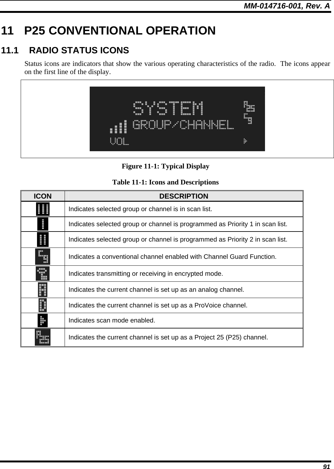
![MM-014716-001, Rev. A 21 PART FUNCTION SCAN Toggles the Scan Mode ON/OFF. • If the Scan Mode is Normal and the Scan Mode is toggled Off, when the Scan Mode is toggled On the Scan Mode will be set to Normal. • If the Scan Mode is Fixed and the Scan Mode is toggled Off when the Scan Mode is toggled On the Scan Mode will be set to Fixed . • If the Scan Mode is Off when the radio boots up when the Scan Mode is toggled On the Scan Mode will be set to Normal. 7.2 POWER UP AND VOLUME CONTROL 7.2.1 Power Up 1. Rotate the Power On-Off/Volume Control knob clockwise to power on the radio. The display will illuminate when the radio powers up. 2. Wait for the power-up sequence to complete, which takes approximately ten (10) seconds. During this time, if enabled for auto registration, the radio is provisioned with a customized user personality designed for the user’s specific needs by the OpenSky network administrator. If this personality contains encrypted talk groups or if the user is authorized for, and intends to use, manual encryption, User Login must be performed. This requires a system model control head so that the User ID and password can be entered. 3. When provisioning is complete, the radio will display the Dwell Display. If User Login is required, the bottom line of the Dwell Display will flash the message “Pls Login.” 7.2.2 Volume Control Turn the Power On-Off/Volume Control knob clockwise to increase the volume and counter-clockwise to decrease the volume. 7.3 SELF-TEST After power-up, the M7300 radio undergoes a multi-function automatic registration procedure. As many as sixteen (16) possible radio profiles are downloaded to the radio from the network in response to the User’s ID. 7.4 LOGIN TO THE NETWORK Login occurs either automatically (auto registration) if the radio has a valid registration or, if enabled and authorized for encryption (Section 7.30), requires the user to enter a User ID and password. If encryption is enabled and authorized on the radio, the user will be prompted to “Pls Login” with the *1 login command, a User ID, and password [System Model Control Head required]. 1. Press *1 (Login command). 2. Enter the full 10-digit User ID. 3. Press the # key. 4. Enter the password.](https://usermanual.wiki/HARRIS/TR-0051-E.Manual-3/User-Guide-992020-Page-21.png)
![MM-014716-001, Rev. A 30 7.14 KEYPAD 7.14.1 Keypad Commands (System Model Control Head) To perform a command from the keypad, press the * key followed by one of the pre-set function keys as follows: Table 7-5: Keypad Function Commands KEYPAD COMMAND FUNCTION *0 Log off command: *0## (logs the user off the system). See page 22 for additional information. *1 Login command: *1<User ID> # <Password> ## (required for encryption). See page 21 for additional information. *4 Enter Scene of Incident Mode (SOI) on specified channel and band: *4#<ccc>#<bb># where ccc is the SOI channel number and bb is the number assigned to each frequency band. Press *40# to exit SOI mode. *6 Go to default profile. *7 Initiate Selective Alert command: *7<Target ID>#[Choose Message]#. See page 40 for additional information. *8 Radio-to-Radio Call command: *8<Selective call number># (PTT to dial). *9 Public Switched Telephone Network (PSTN) Call command: *9 <telephone number># (PTT to dial). See page 42 for additional information. *32 Begin Manual Encryption command: *32<Pre-Determined Encryption Key ># 1 – 16 digit encryption key for 128 bit encryption; 17 – 32 digit encryption key for 256 bit encryption. See page 46 for additional information. *33 End Manual Encryption command: *33#](https://usermanual.wiki/HARRIS/TR-0051-E.Manual-3/User-Guide-992020-Page-30.png)
![MM-014716-001, Rev. A 47 7.31 PRESET BUTTONS The front panel contains three buttons labeled A, B, and C. By holding one of these buttons down for approximately three (3) seconds, the following current information is saved to the function of that button: • Selected talk group • Selected profile • Selected priority talk group • Lockouts • Scan mode • Intercom mode Presets are saved and restored to/from non-volatile memory. Changing the User ID (login as a different user) will clear the presets since they are stored on a per-user basis. Changing control heads will not recall presets for the previous control head. Preset button C can be configured via programming to reboot the radio into a particular application mode. Contact your system administrator to determine if this feature is enabled in your radio. 7.32 DYNAMIC REGROUPING Dynamic regrouping requires that the network administrator determine which radio users should be formed into an impromptu talk group to respond to particular emergency conditions. The administrator will edit the personalities of the affected radios to include an emergency profile and then page the affected radios to re-register with the network to receive their edited personalities. In response, affected radios automatically re-register to receive their edited personalities. During re-registration, subscriber equipment will default to the emergency profile selected by the administrator. 7.33 GPS COORDINATES The radio’s current latitude and longitude coordinates may be displayed using the “GPS” menu. The following procedure assumes a GPS antenna is connected to the radio and it is receiving adequate signals from GPS satellites: 1. Scroll through the menu until the “GPS” menu appears in the bottom line of the display. 2. Current GPS coordinate latitude and longitude data continuously scrolls in the top line of the display in a degrees:minutes:seconds format. If the internal GPS receiver’s data is expired (30 minutes or more) or unavailable, the radio uses the serving base station’s coordinates [GPS (Site) is displayed]. The GPS Menu will also indicate if the data is aged (2 minutes or more) [GPS (Aged) is displayed] 7.34 SCENE-OF-INCIDENT MODE The Scene-of-Incident mode (SOI) is user-selectable. The SOI mode provides a local repeater function (V-TAC) with no network connection](https://usermanual.wiki/HARRIS/TR-0051-E.Manual-3/User-Guide-992020-Page-47.png)
![MM-014716-001, Rev. A 70 9.9.2 ProScan™ The radio can be programmed for ProScan™ system scan operation for multi-site applications depending on the version of radio flash code. ProScan provides the radio with the ability to select a new system for the radio to communicate on, when the selected system drops below a predefined level. This is accomplished by enabling each radio to analyze the signal quality of its current control channel and compare it with the signal quality of the control channel for each site in its adjacency scan list. The signal quality metric used for the ProScan algorithm is based on a combination of both Received Signal Strength Indicator [RSSI] and Control Channel Verification [CCV] measurements. When the selected system’s signal quality level degrades below a pre-programmed level, the radio will begin to look for a better control channel. Once a control channel that exceeds the pre-programmed parameters is found, the radio will change to the new system and emit a tone. If the control channel is completely lost, the radio enters Wide Area System Scanning and search the programmed adjacent systems until a suitable control channel is found. 9.9.3 Priority System Scan The radio can also be programmed for Priority System Scan. (To ensure that this feature operates correctly, the control channel of the priority system must be located on channel one unless you are using the ProScan algorithm.) The priority system is the desired or preferred system. While receiving the control channel of the selected system, the radio will periodically leave the selected system and search for the control channel of the priority system at a programmable rate. The programmable rate is defined by the value in the Priority Scan Time control, (unless the ProSound/ProScan algorithm is enabled as explained below). This priority scan timer is reset each time the PTT button is pressed or when a call is received. If the priority system control channel is found, or meets the predefined ProScan criteria, the radio will automatically switch to the priority system. 9.9.4 When Wide Area System Scan Is Enabled If the radio cannot find the control channel of the selected system and begins Wide Area System Scan (WA Scan), the radio will only scan for the priority system control channel if the priority system is in the WA Scan list. 9.9.5 When ProScan Is Enabled The radio monitors the priority system and will switch to the priority system if the priority system meets the criteria defined in the “ProSound/ProScan Options” dialog box. If ProScan is enabled, the rate at which the radio will scan for the priority system is defined by the System Sample Time control. 9.9.6 Menu Selection Press MENU and then use the ramp control to scroll through the selections until SYS SCAN is displayed. Then press MENU to toggle the System Scan state. The SYSC ON or SYSC OFF display message is displayed for two seconds to show the new state. 9.9.7 Pre-Programmed Keypad Key Press the pre-programmed key and the SYSC ON or SYSC OFF display message is displayed for two seconds to show the new state.](https://usermanual.wiki/HARRIS/TR-0051-E.Manual-3/User-Guide-992020-Page-70.png)