HARRIS TR-0051-E M7300/M5300 Mobile Radio User Manual Manual
HARRIS CORPORATION M7300/M5300 Mobile Radio Manual
UserManual.wiki
>
HARRIS
>
TR-0051-E User Manual
>
Manual
Contents
1.
Manual
2.
Manual 1
3.
Manual 2
4.
Manual 3
Manual
Navigation menu
Upload a User Manual
Namespaces
Wiki Guide
HTML
PDF
Info
Views
User Manual
Discussion / Help
Navigation


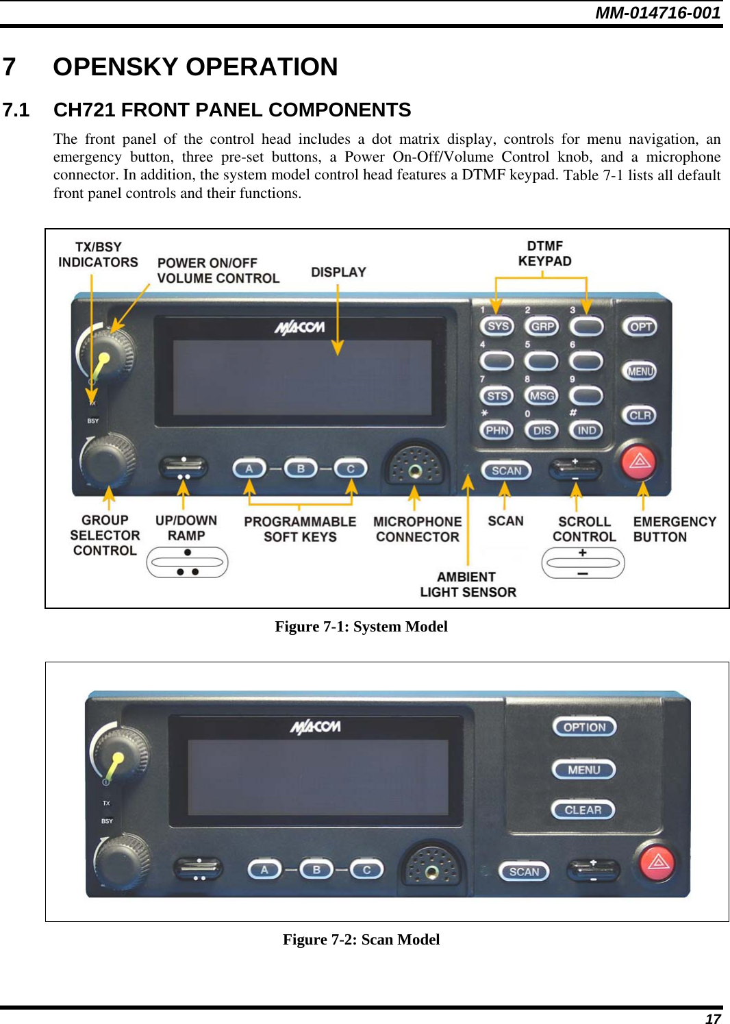
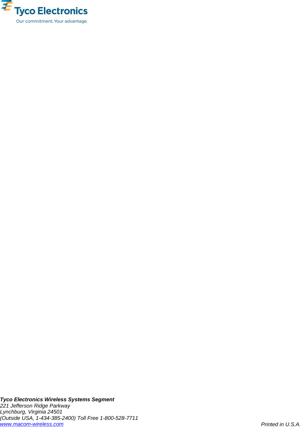
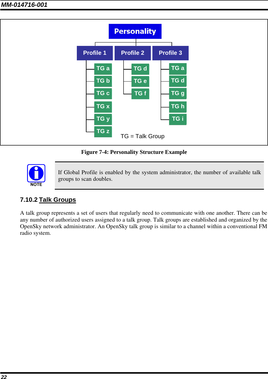
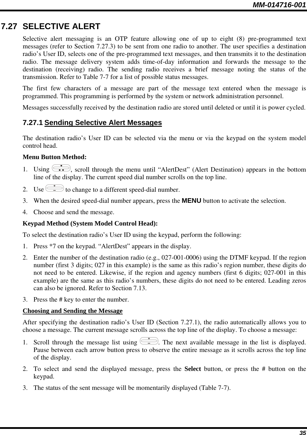
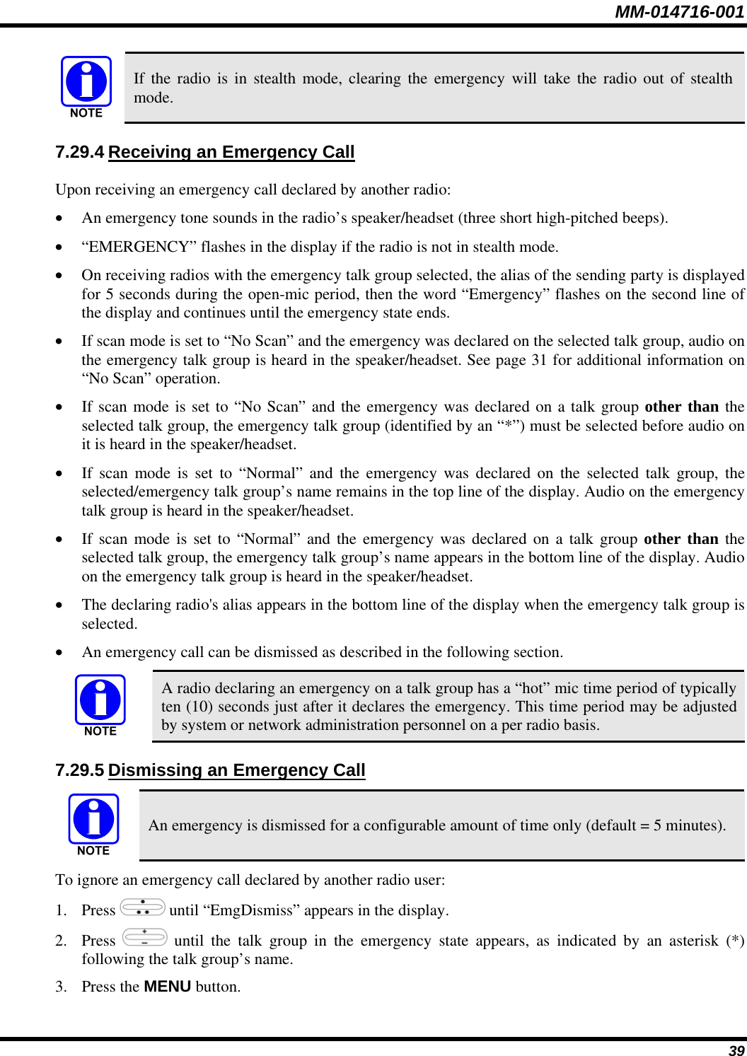
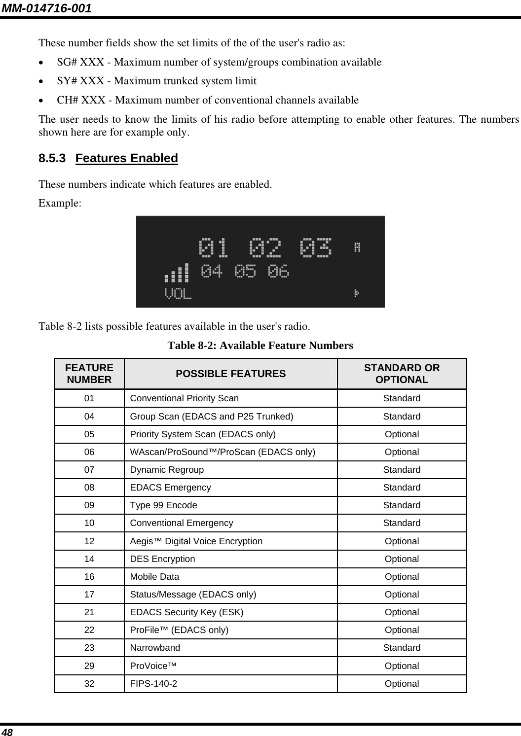
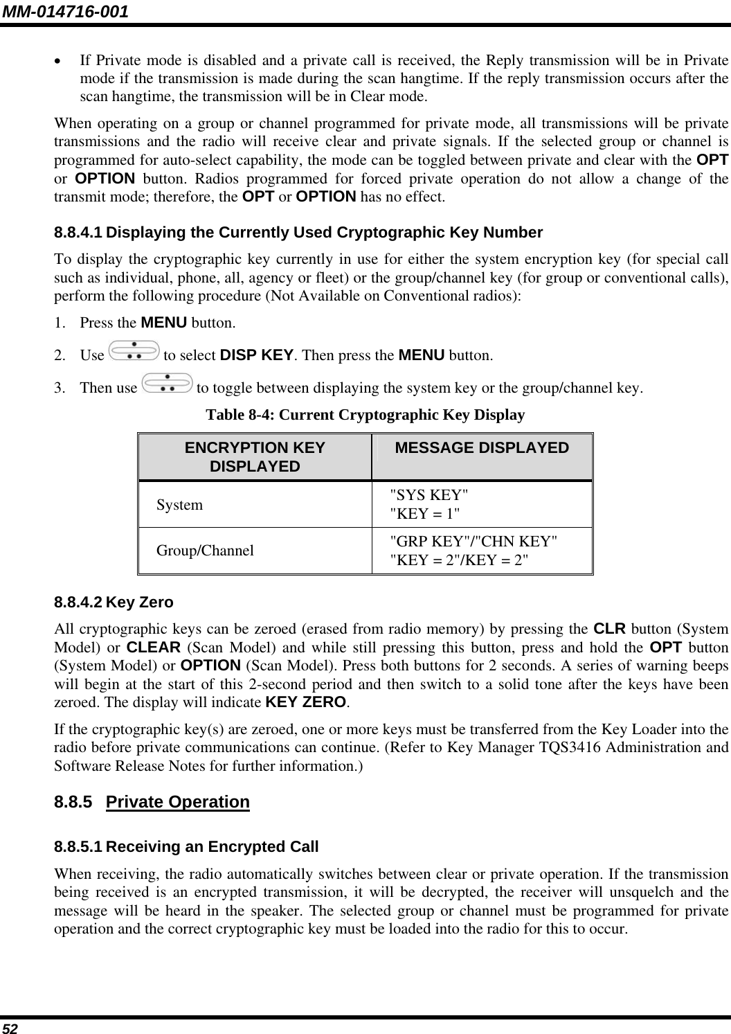
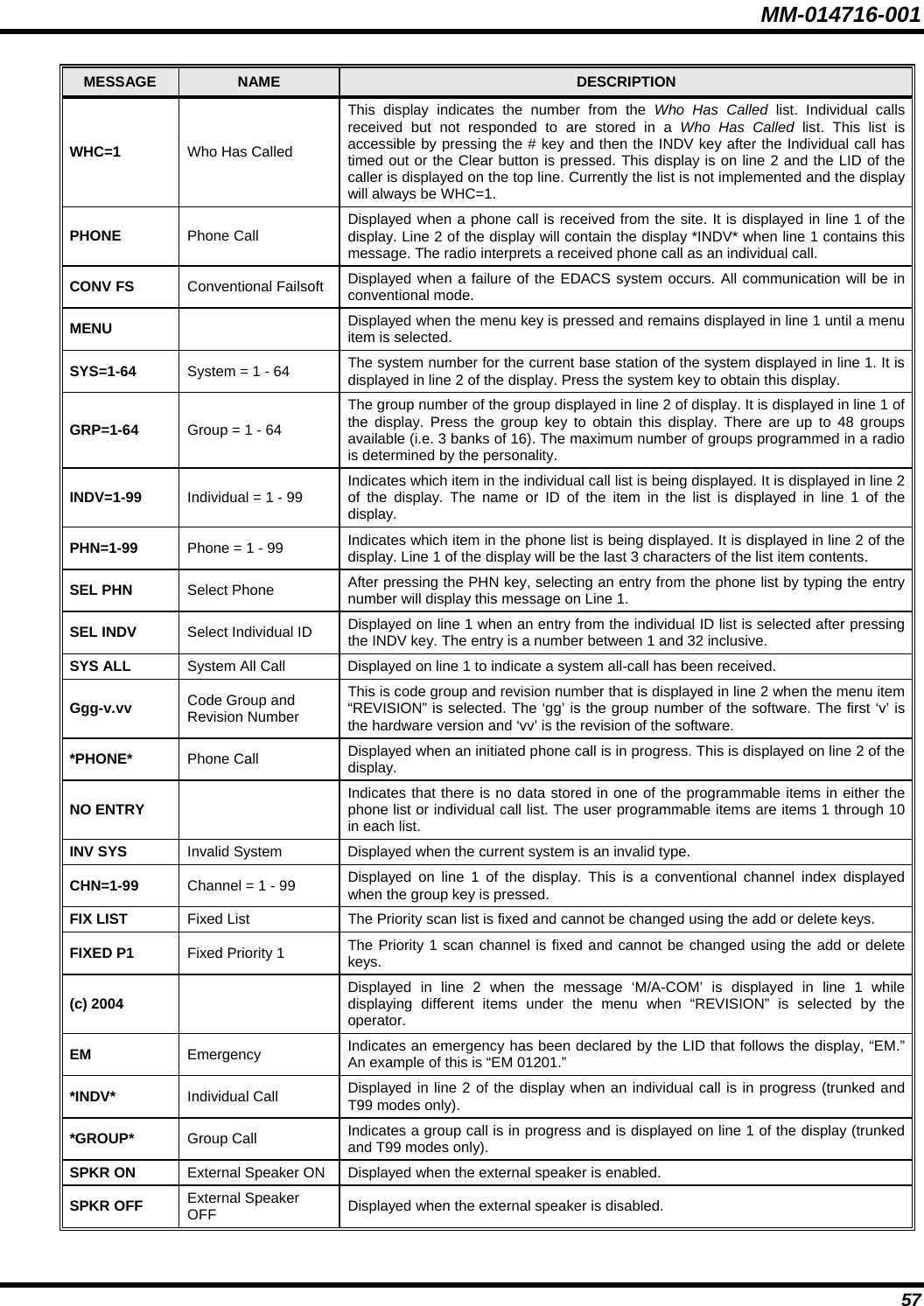
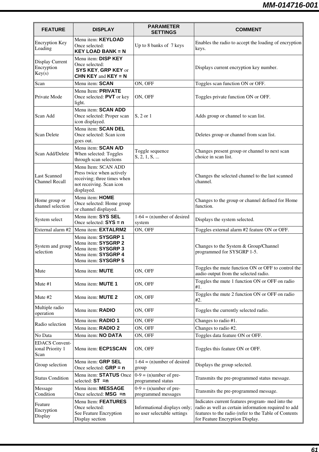
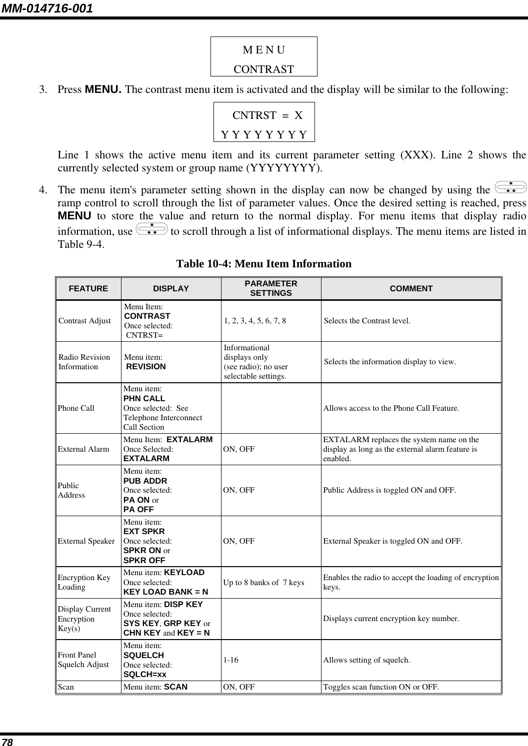
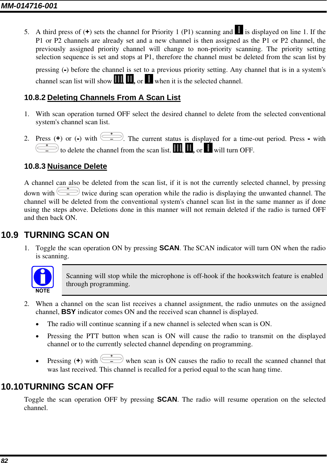
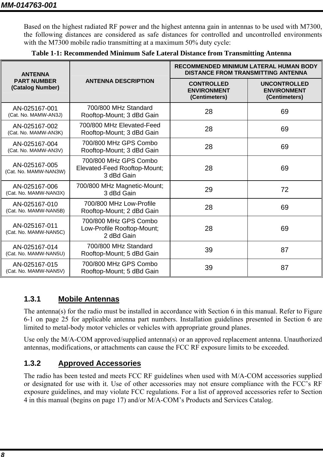
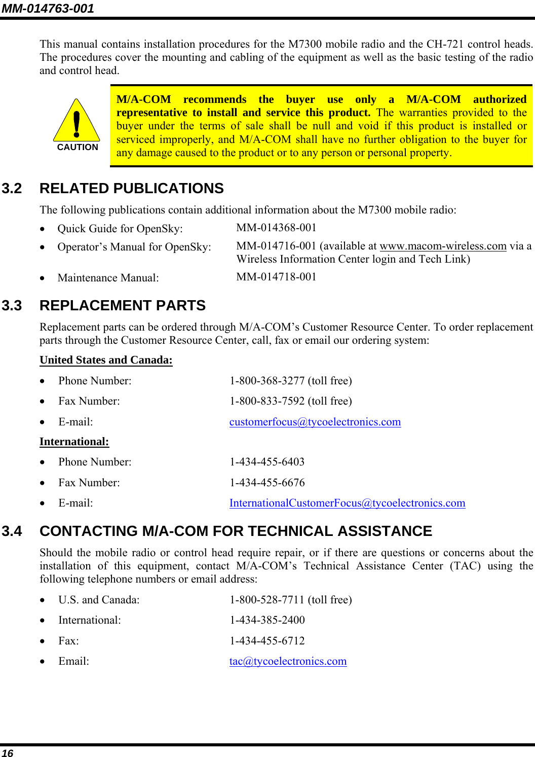
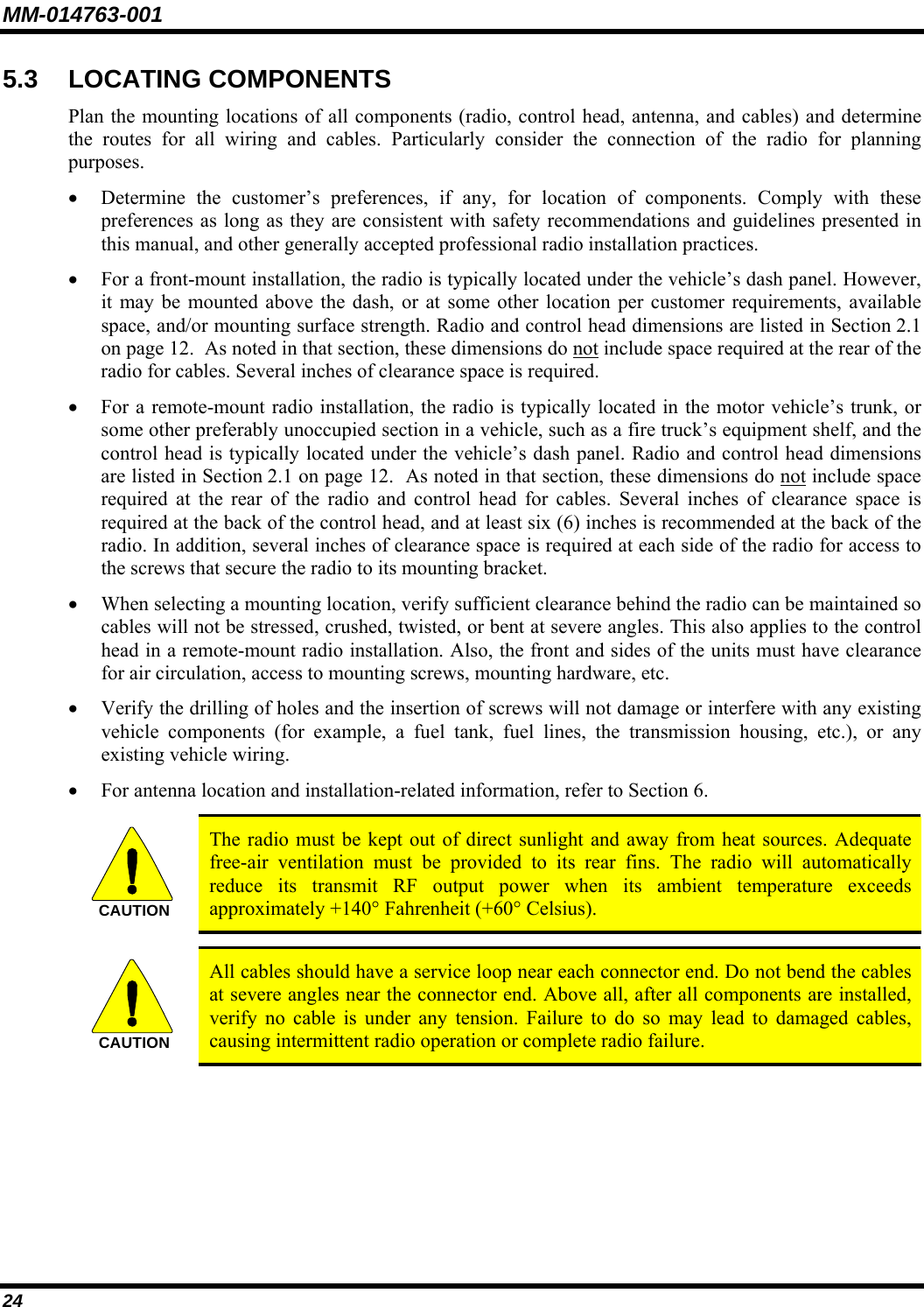
![MM-014716-001 19 2. Wait for the power-up sequence to complete, which takes approximately ten (10) seconds. During this time, if enabled for auto registration, the radio is provisioned with a customized user personality designed for the user’s specific needs by the OpenSky network administrator. If this personality contains encrypted talk groups or if the user is authorized for, and intends to use, manual encryption, User Login must be performed. This requires a system model control head so that the User ID and password can be entered. 3. When provisioning is complete, the radio will display the Dwell Display. If User Login is required, the bottom line of the Dwell Display will flash the message “Pls Login.” 7.2.2 Volume Control Turn the Power On-Off/Volume Control knob clockwise to increase the volume and counter-clockwise to decrease the volume. 7.3 SELF-TEST After power-up, the M7300 radio undergoes a multi-function automatic registration procedure. As many as sixteen (16) possible radio profiles are downloaded to the radio from the network in response to the User’s ID. 7.4 LOGIN TO THE NETWORK Login occurs either automatically (auto registration) if the radio has a valid registration or, if enabled and authorized for encryption (Section 7.30), requires the user to enter a User ID and password. If encryption is enabled and authorized on the radio, the user will be prompted to “Pls Login” with the *1 login command, a User ID, and password [System Model Control Head required]. 1. Press *1 (Login command). 2. Enter the full 10-digit User ID. 3. Press the # key. 4. Enter the password. • If the radio is configured for alpha-numeric passwords and the password has consecutive duplicate numbers (“MES33” for example), enter # between the consecutive duplicate numbers so the radio will not interpret the entry as a letter (“D” in this example). • If the radio is configured for numeric-only passwords, do not enter # between duplicated numbers. 5. Press the # key twice. The User ID may be remembered from the previous log-in. (Refer to Section 7.5 for further details regarding log-off commands.) The password will be established before the radio is put into operation. Contact the local OpenSky network administrator for more information. If necessary, contact radio system administration personnel for log-in assistance and/or radio-specific log-in instructions.](https://usermanual.wiki/HARRIS/TR-0051-E.Manual/User-Guide-949280-Page-20.png)
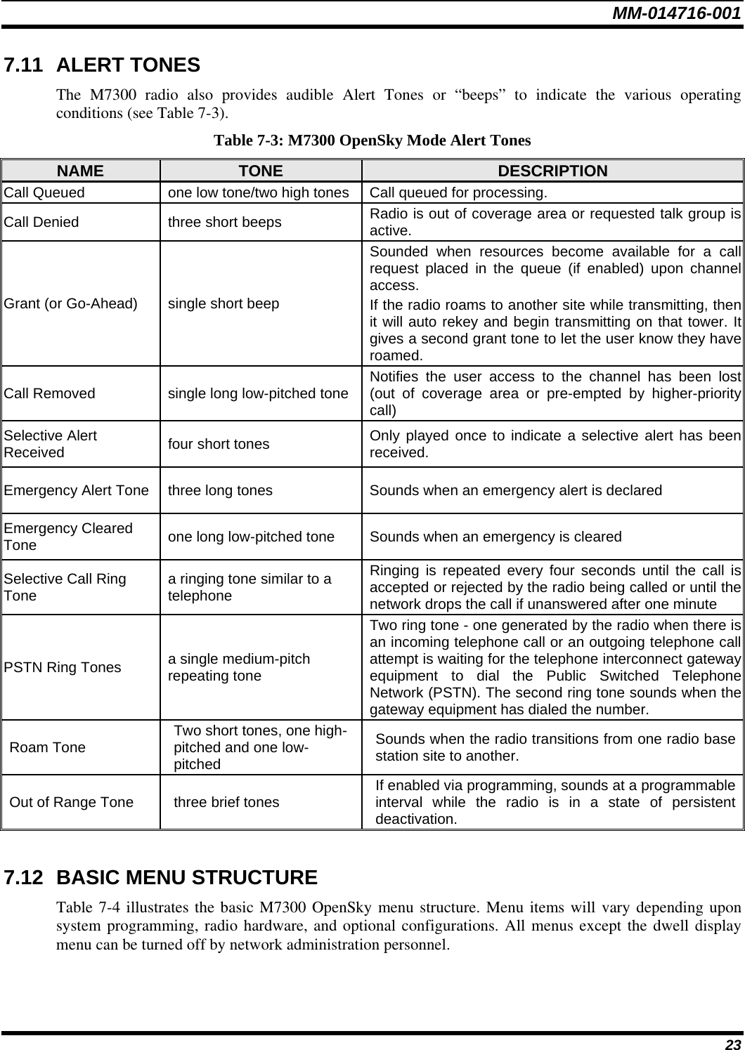
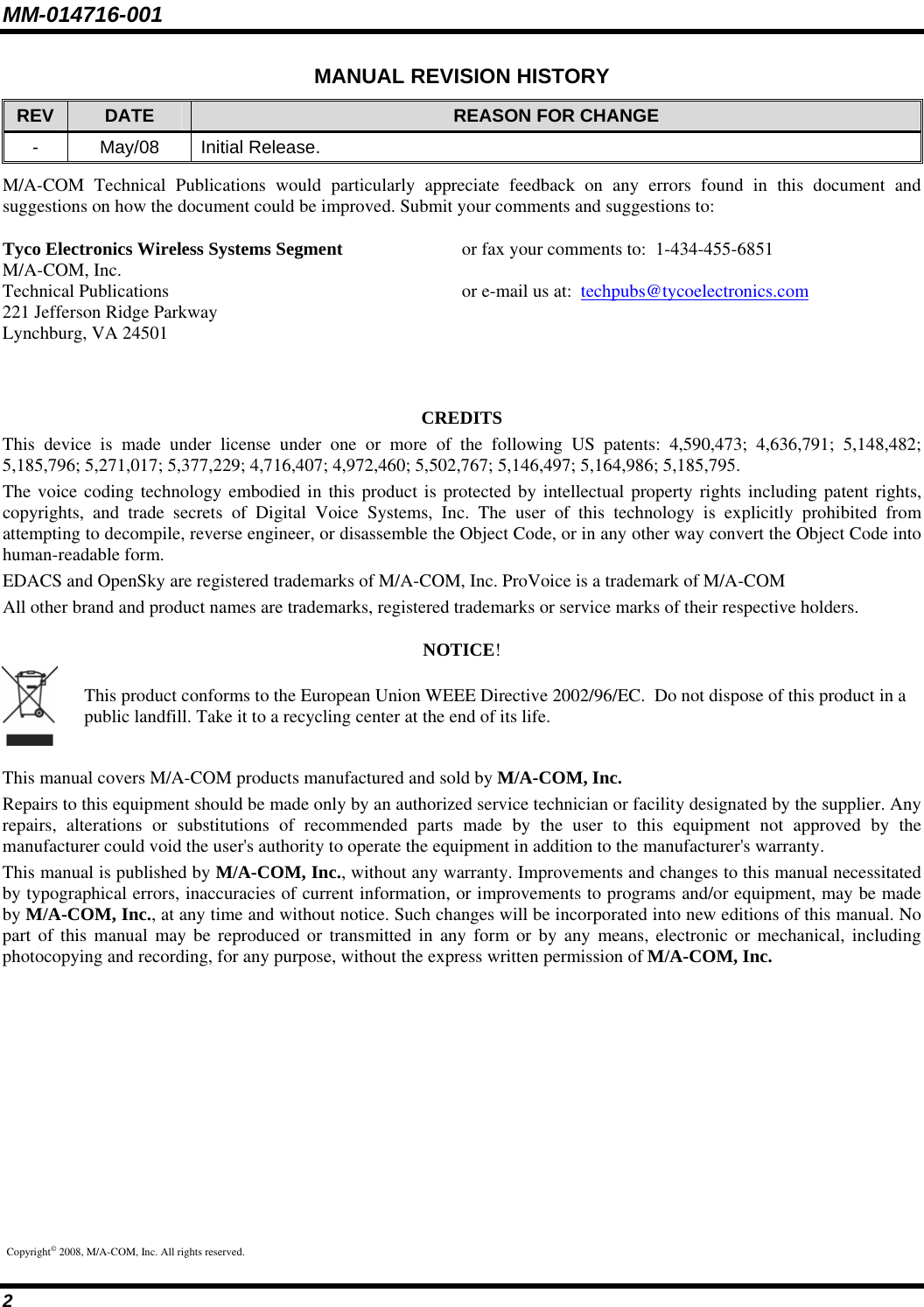
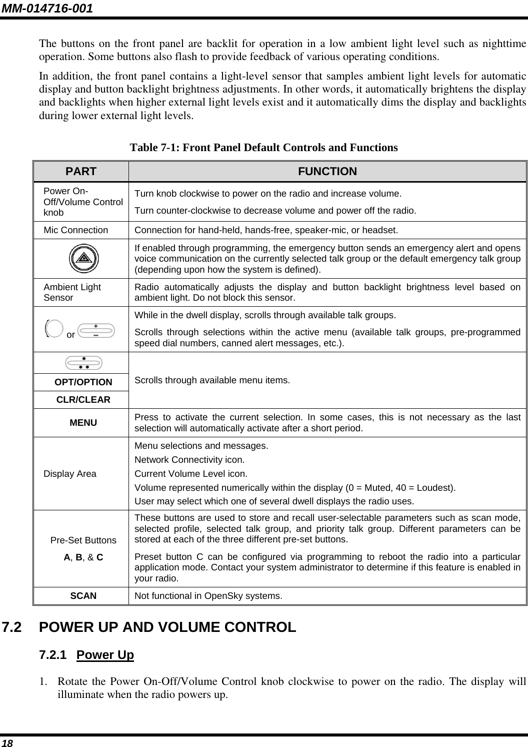
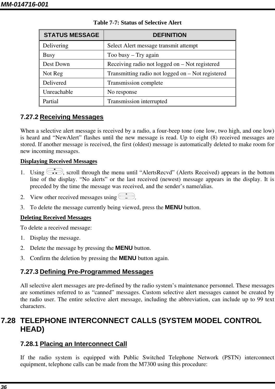
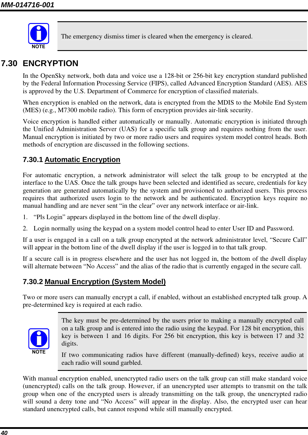
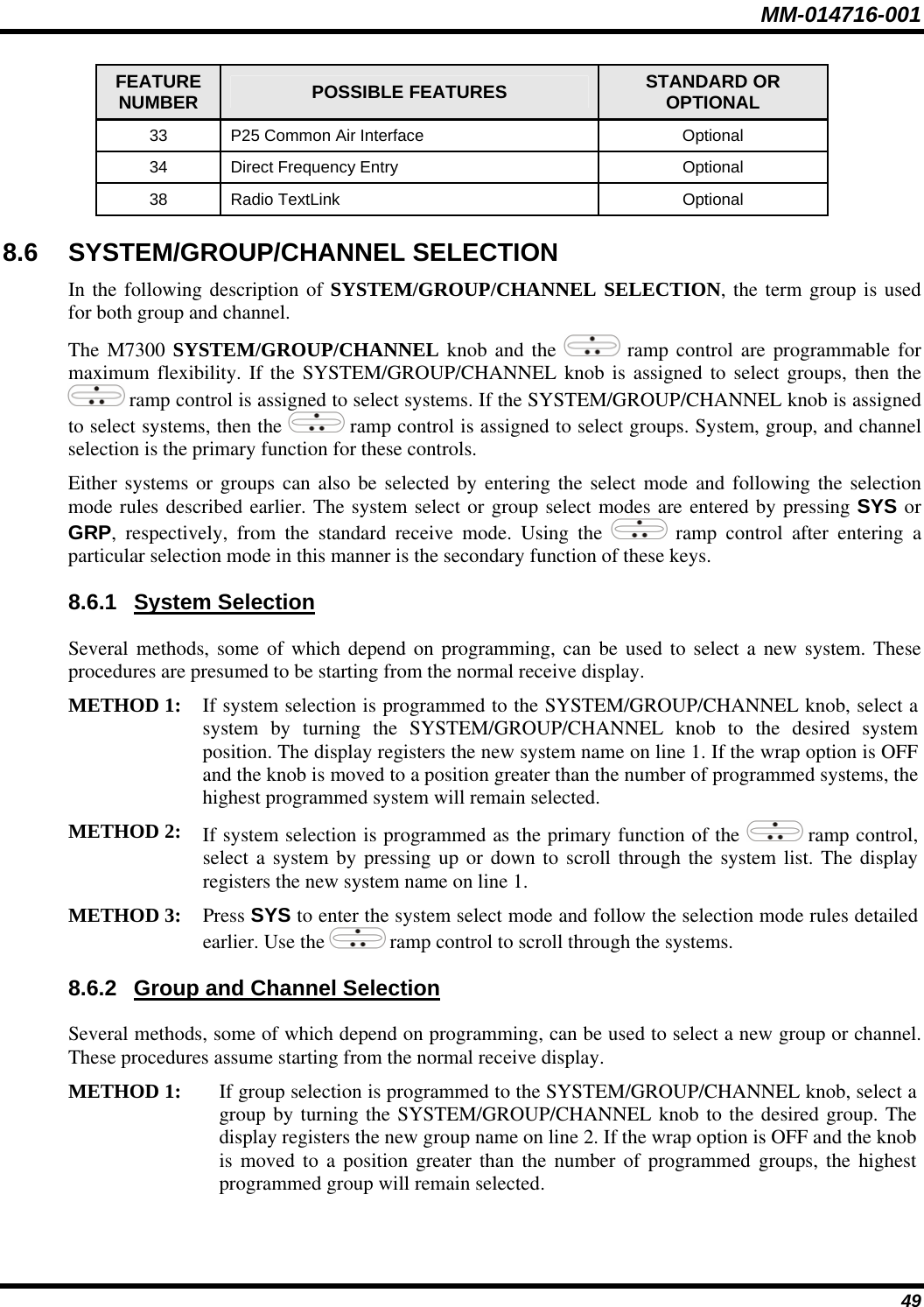
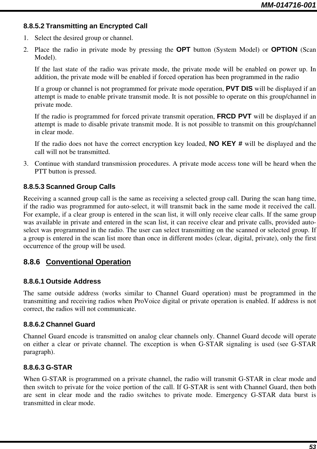
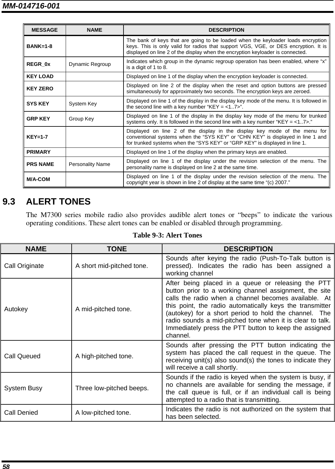
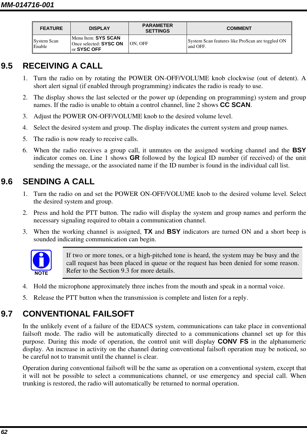
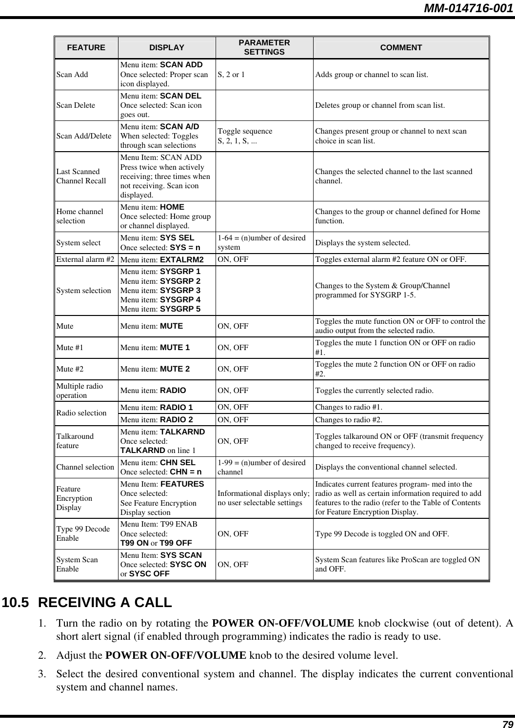
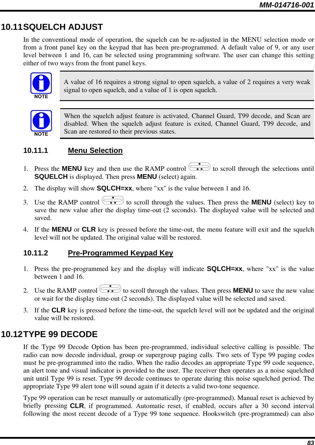
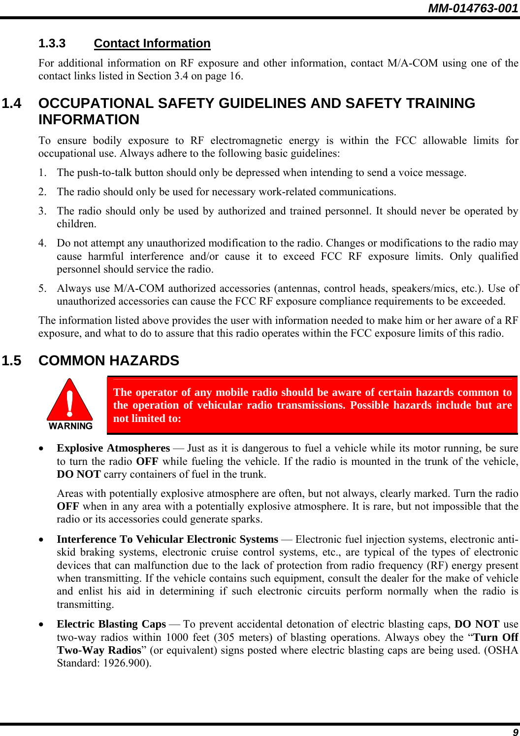
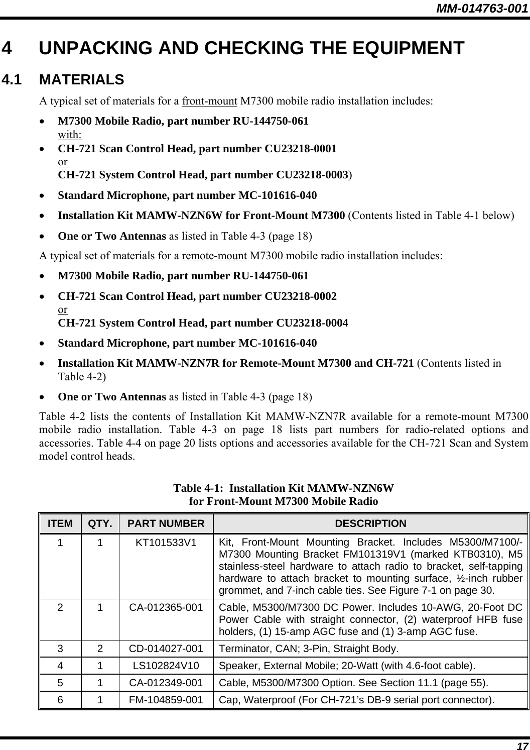
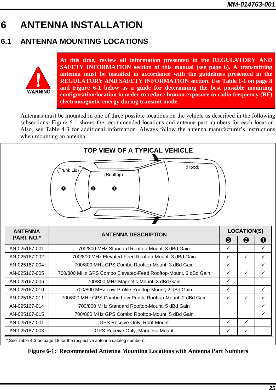
![MM-014716-001 26 7.13 DUAL-TONE MULTI-FREQUENCY Dual-Tone Multi-Frequency (DTMF) is the system used by touch-tone telephones. DTMF assigns a specific tone frequency to each key so a microprocessor can easily identify its activation. The radio supports DTMF with a system model control head (Figure 7-1). This allows for specific tasks such as entering a user ID and password, or selective calling. When a key on the DTMF keypad is pressed, the DTMF tone is played through the radio’s speaker. 7.14 KEYPAD COMMANDS (SYSTEM MODEL CONTROL HEAD) To perform a command from the keypad, press the * key followed by one of the pre-set function keys as follows: Table 7-5: Keypad Function Commands *0 Log-off command: *0## (logs the user off the system). See page 20 for additional information. *1 Log-in command: *1<User ID> # <Password> ## (required for encryption). See page 19 for additional information. *4 Enter Scene of Incident Mode (SOI) on specified channel and band: *4#<channel>#<Band># *4# Exit SOI Mode. *6 Go to default profile: Selects default profile if the radio is not voice registered. *7 Initiate Selective Alert command: *7<Target ID>#[Choose Message]#. See page 35 for additional information. *8 Radio-to-Radio Call command: Selective call number # (PTT to dial). *9 Public Switched Telephone Network (PSTN) Call command: See page 36 for additional information. *32 Begin Manual Encryption command: *32<Pre-Determined Encryption Key ># 1 – 16 digit encryption key for 128 bit encryption; 17 – 32 digit encryption key for 256 bit encryption. See page 40 for additional information. *33 End Manual Encryption command. 7.14.1 Password Entry Password entry requires a system model control head. Password characters are encrypted on the display using symbols to indicate the entry. The encryption symbols for each entry will appear in the display as they are scrolled through, for example: '-' and '+'. Press the # key twice to complete the entry process. If the password is wrong, the radio will not successfully register with the network for wide area voice reception. The radio can still be used in single-site mode.](https://usermanual.wiki/HARRIS/TR-0051-E.Manual/User-Guide-949280-Page-27.png)
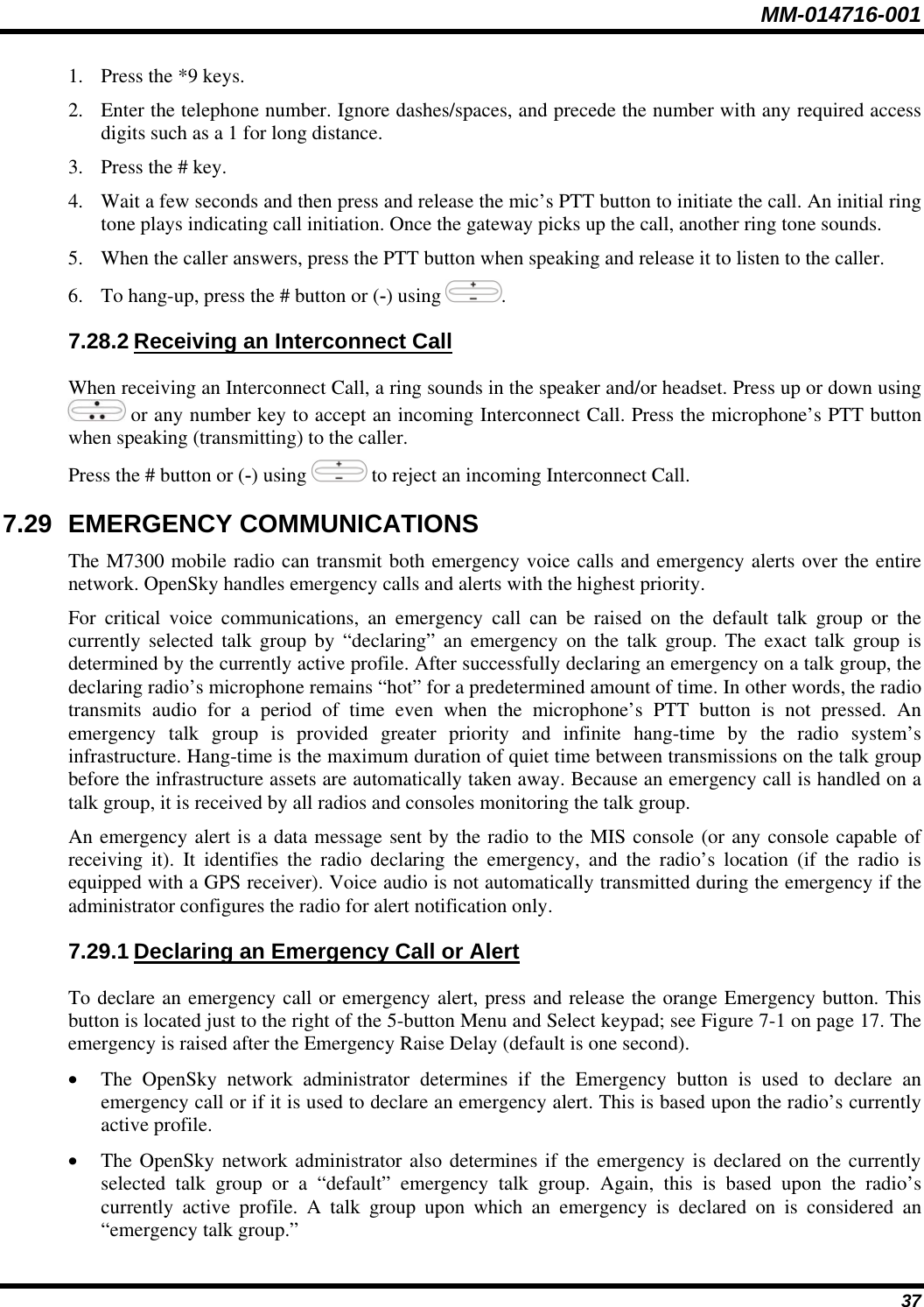
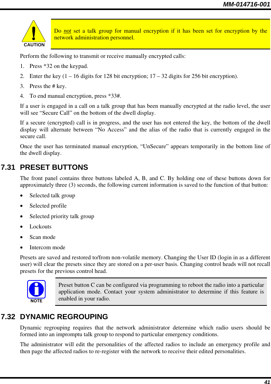
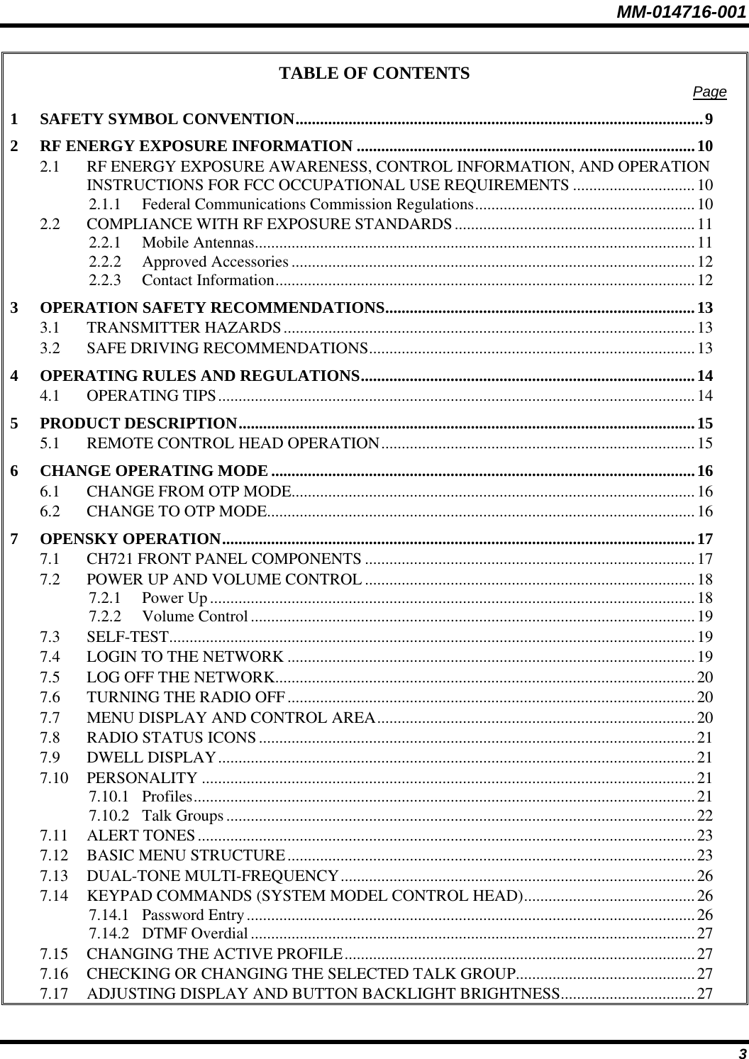
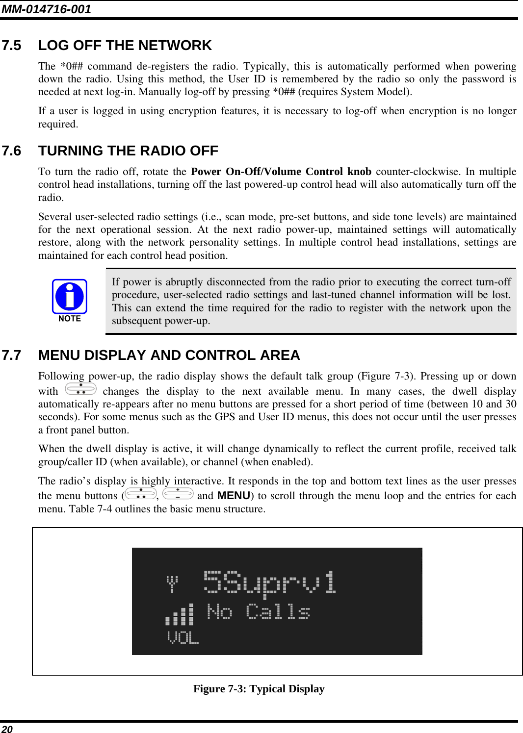
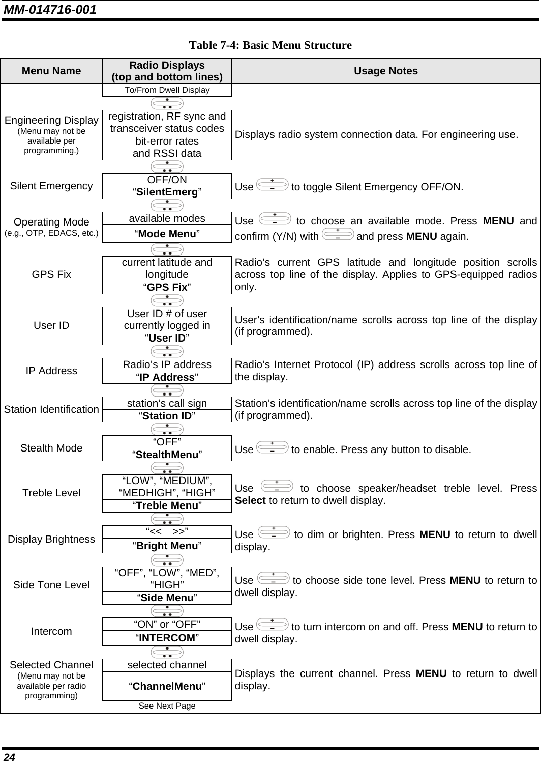
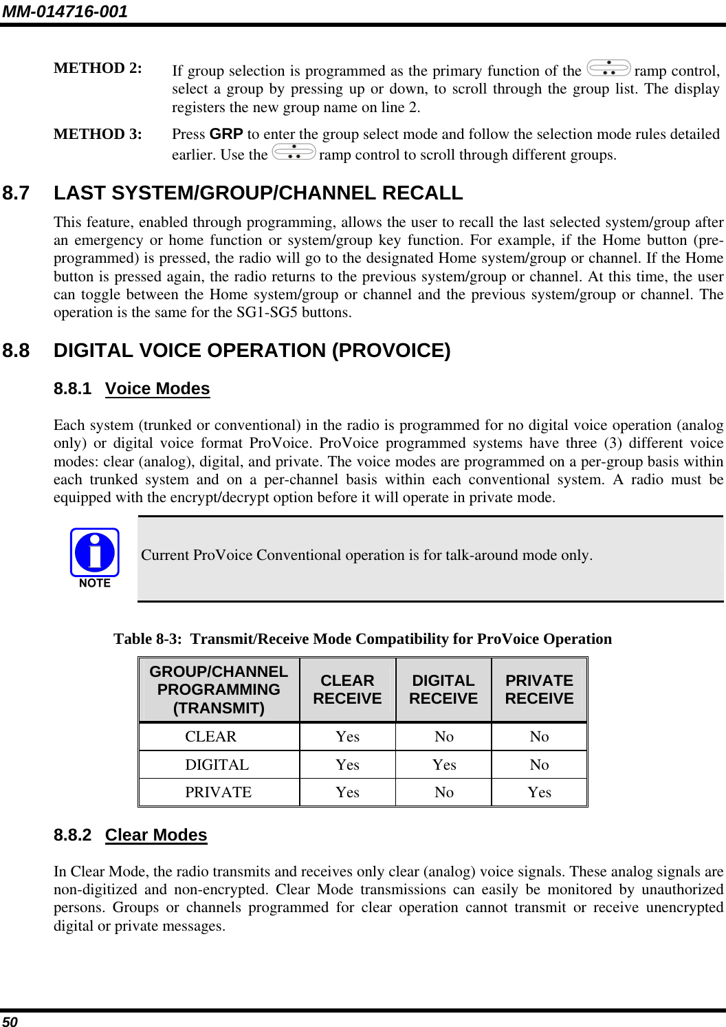
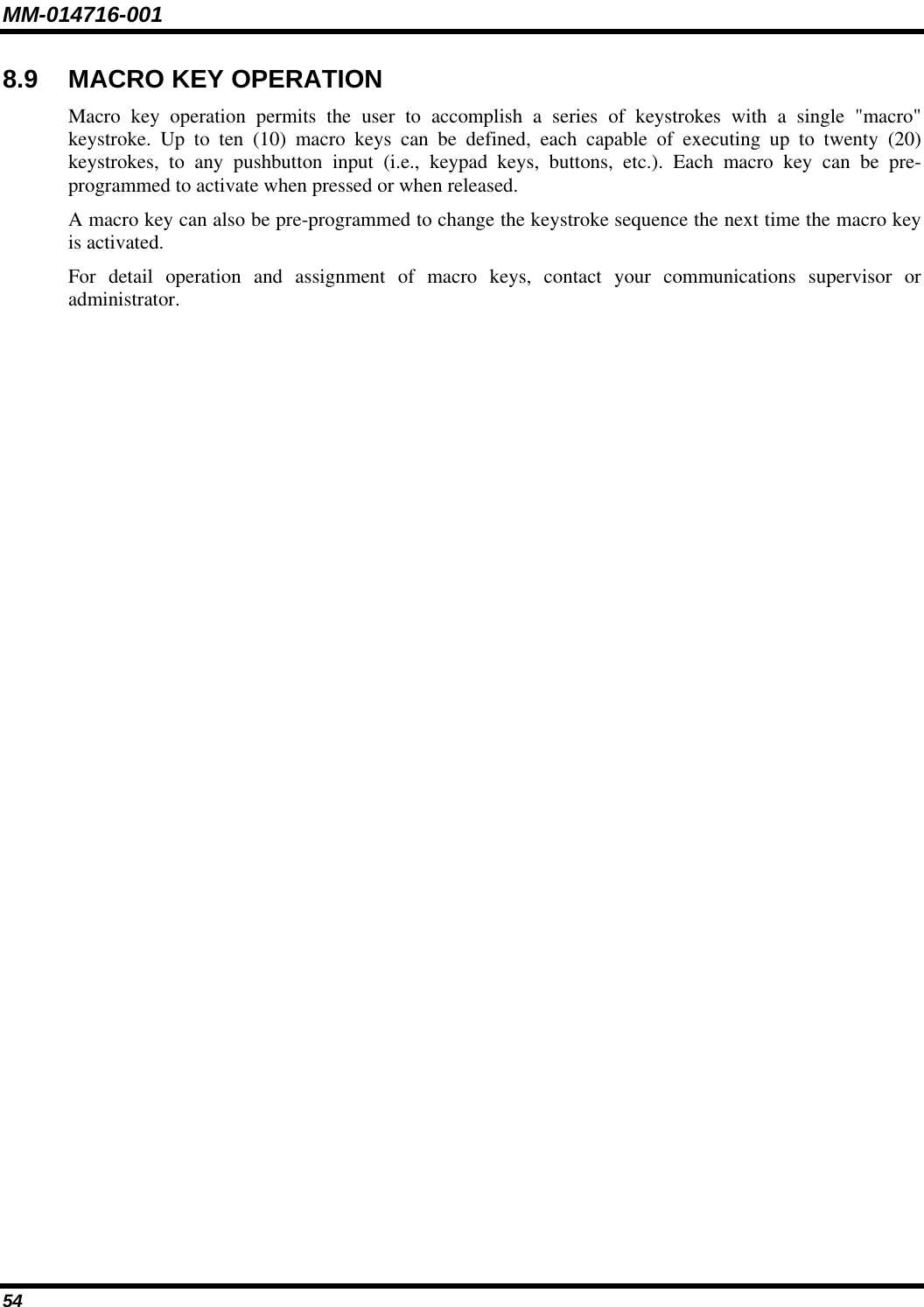
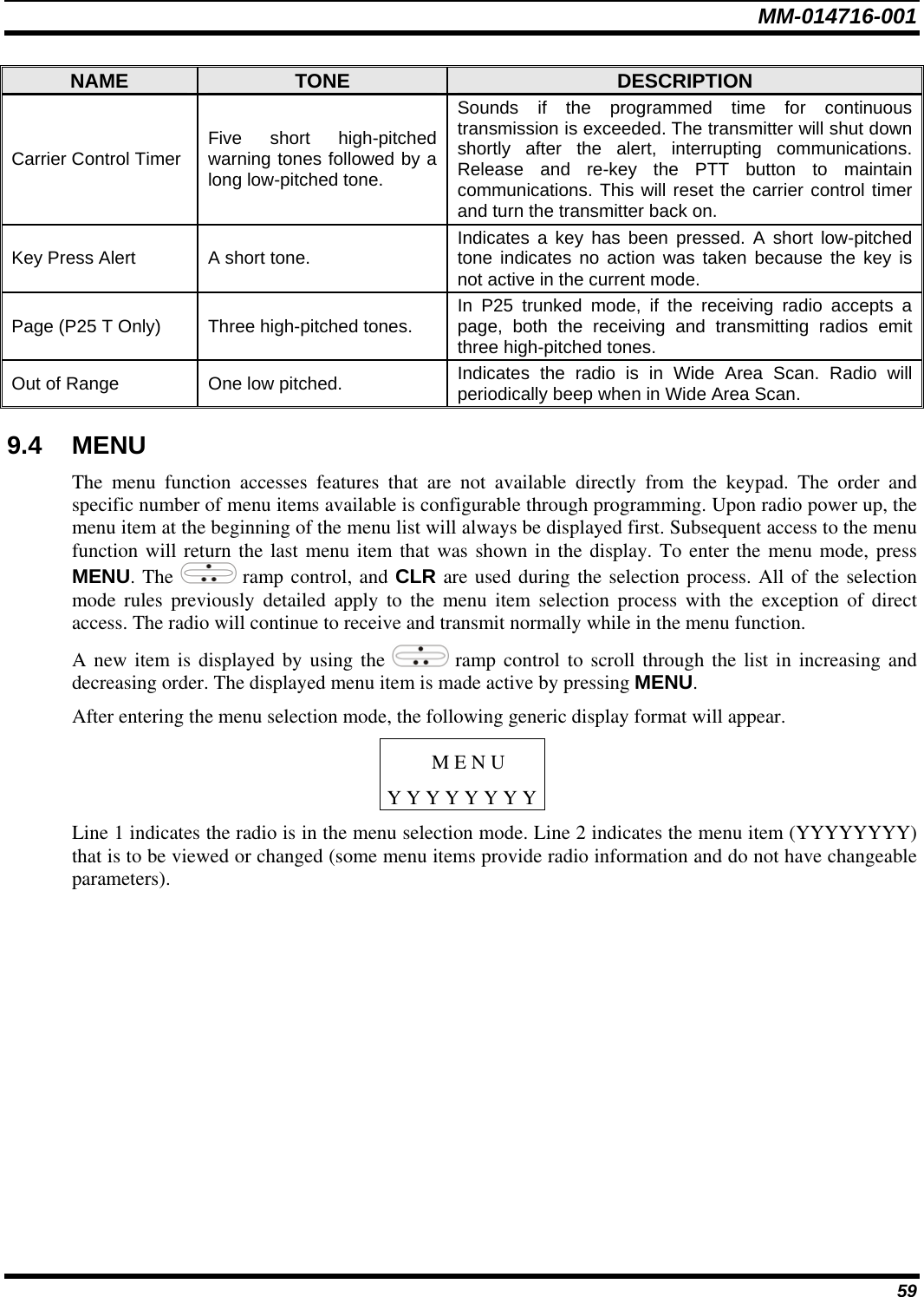
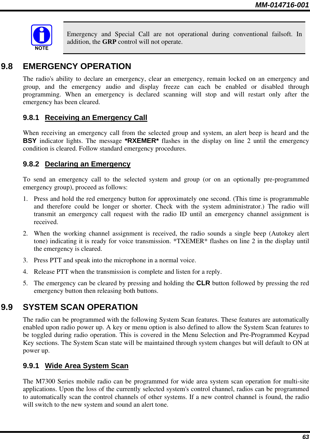
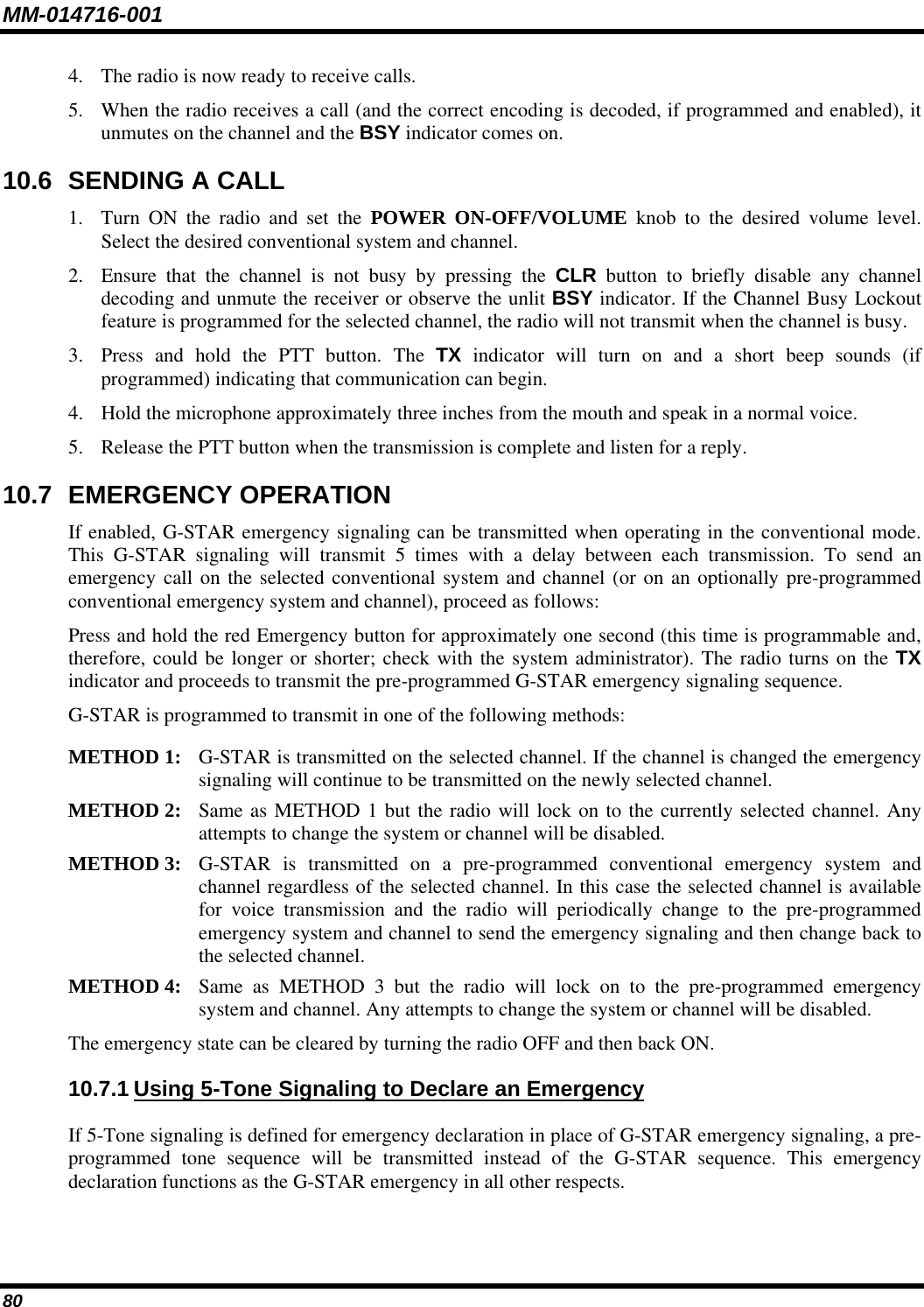
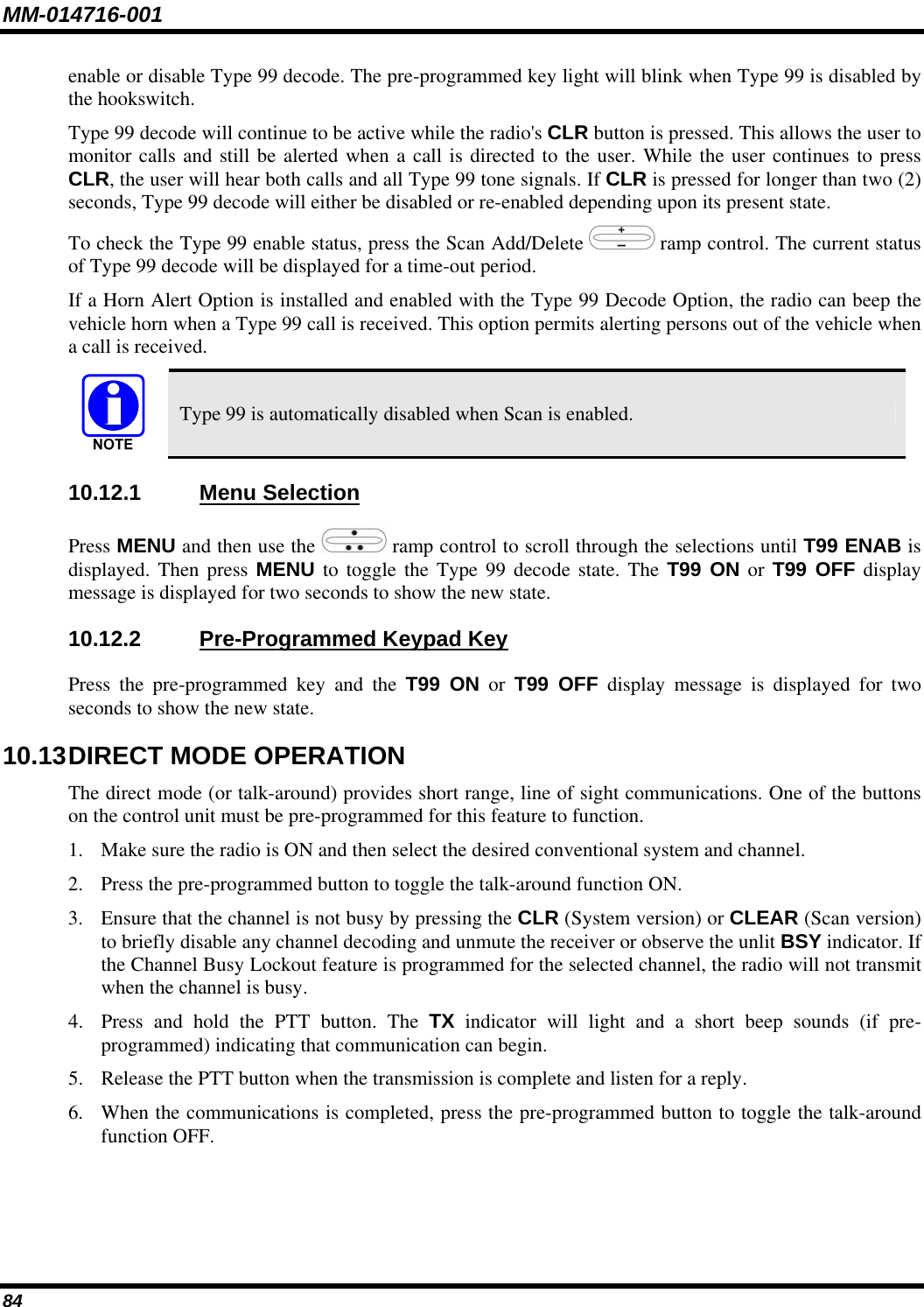
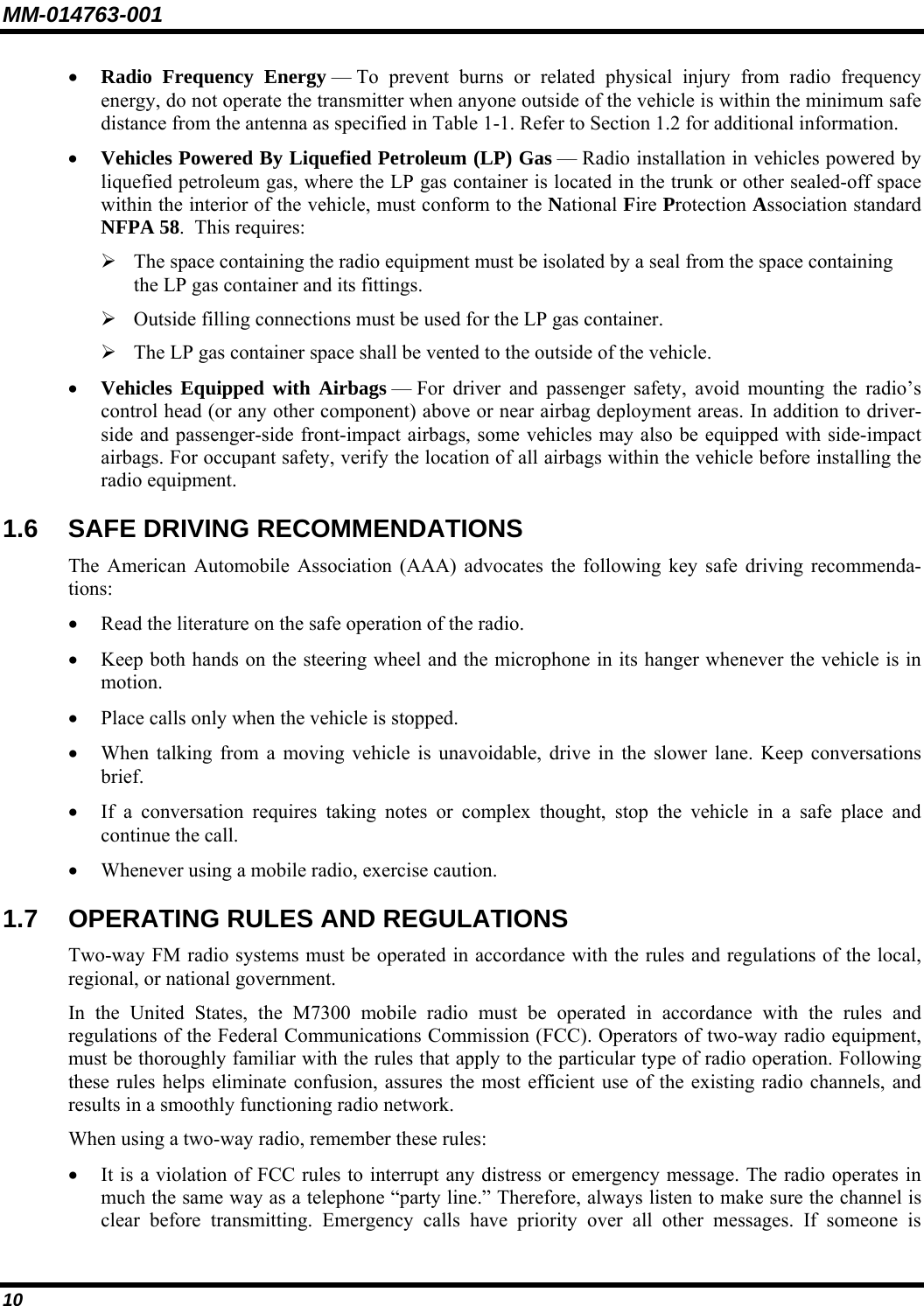
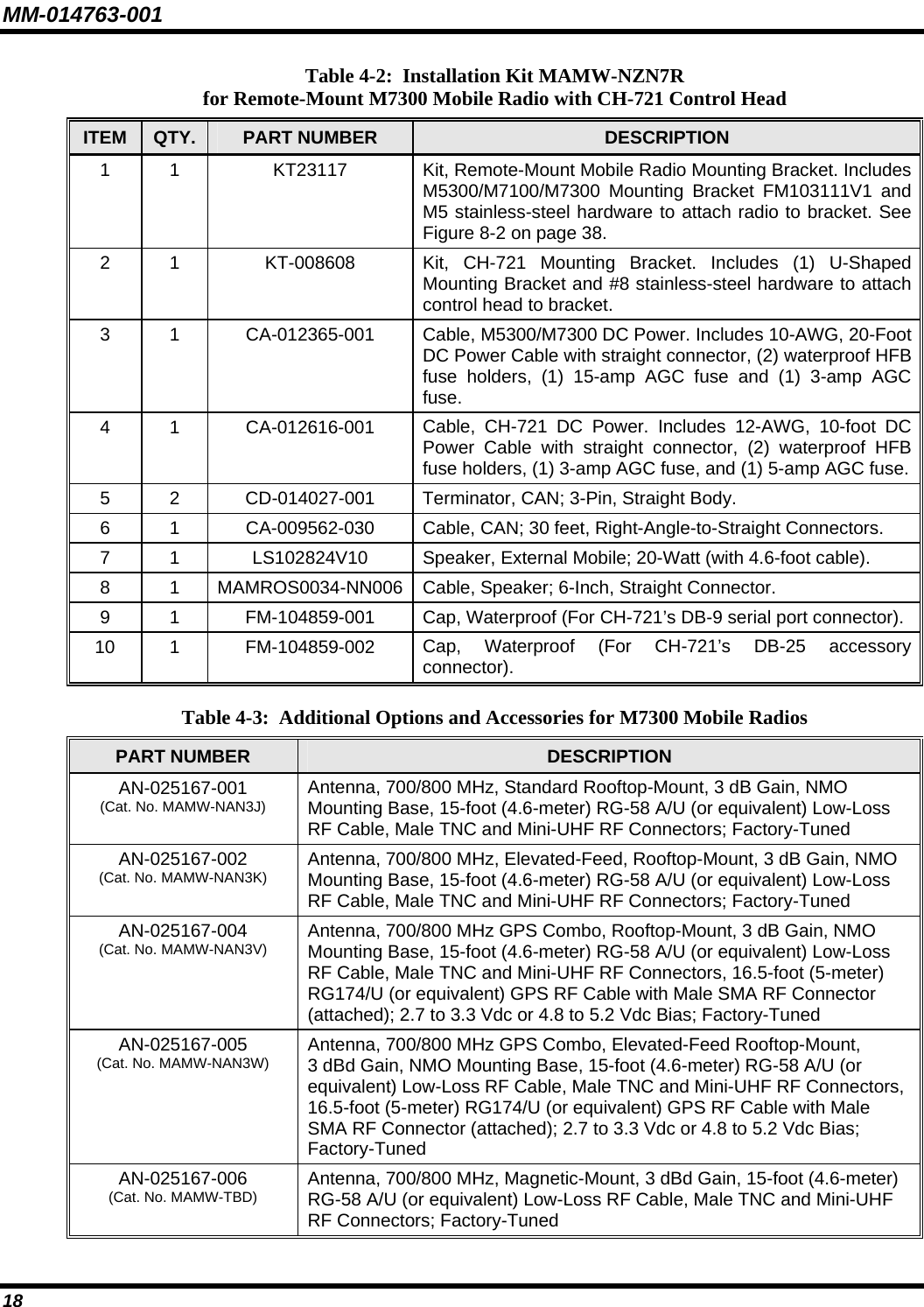
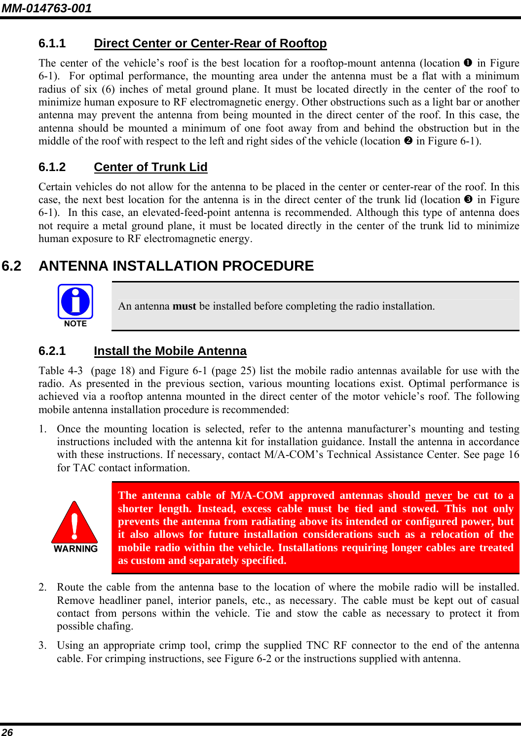
![MM-014716-001 42 In response, affected radios automatically re-register to receive their edited personalities. During re-registration, subscriber equipment will default to the emergency profile selected by the administrator. 7.33 GPS COORDINATES The radio’s current latitude and longitude coordinates may be displayed using the “GPS” menu. The following procedure assumes a GPS antenna is connected to the radio and it is receiving adequate signals from GPS satellites: 1. Press until the “GPS” menu appears in the bottom line of the display. Current GPS coordinate latitude and longitude data continuously scrolls in the top line of the display in a degrees:minutes:seconds format. 2. Use to change to another menu. If the internal GPS receiver’s data is expired (30 minutes or more) or unavailable, the radio uses the serving base station’s coordinates [GPS (Site) is displayed]. The GPS Menu will also indicate if the data is aged (2 minutes or more) [GPS (Aged) is displayed]](https://usermanual.wiki/HARRIS/TR-0051-E.Manual/User-Guide-949280-Page-43.png)
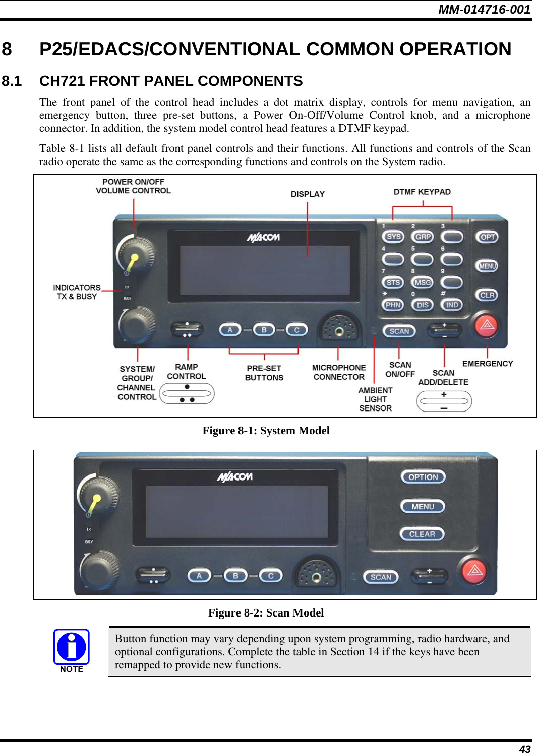
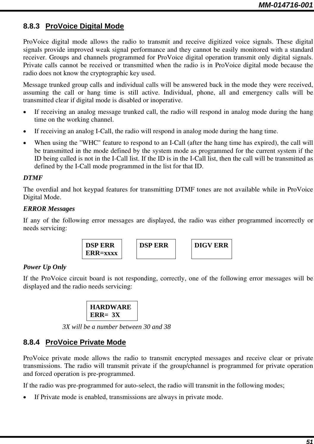
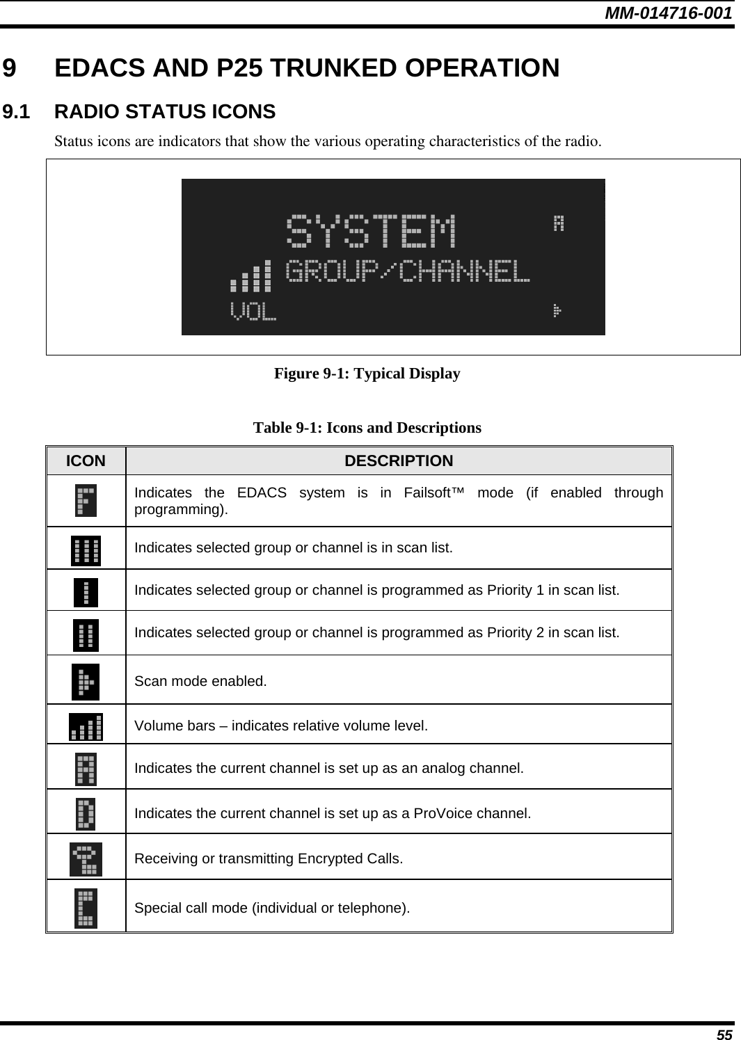

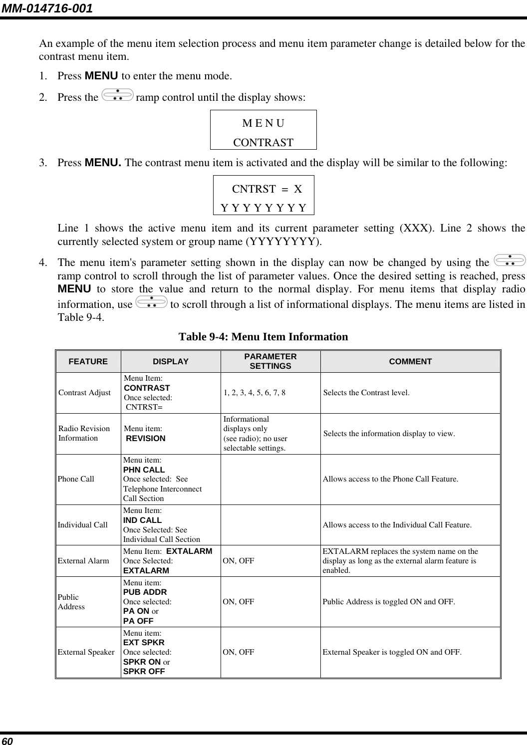
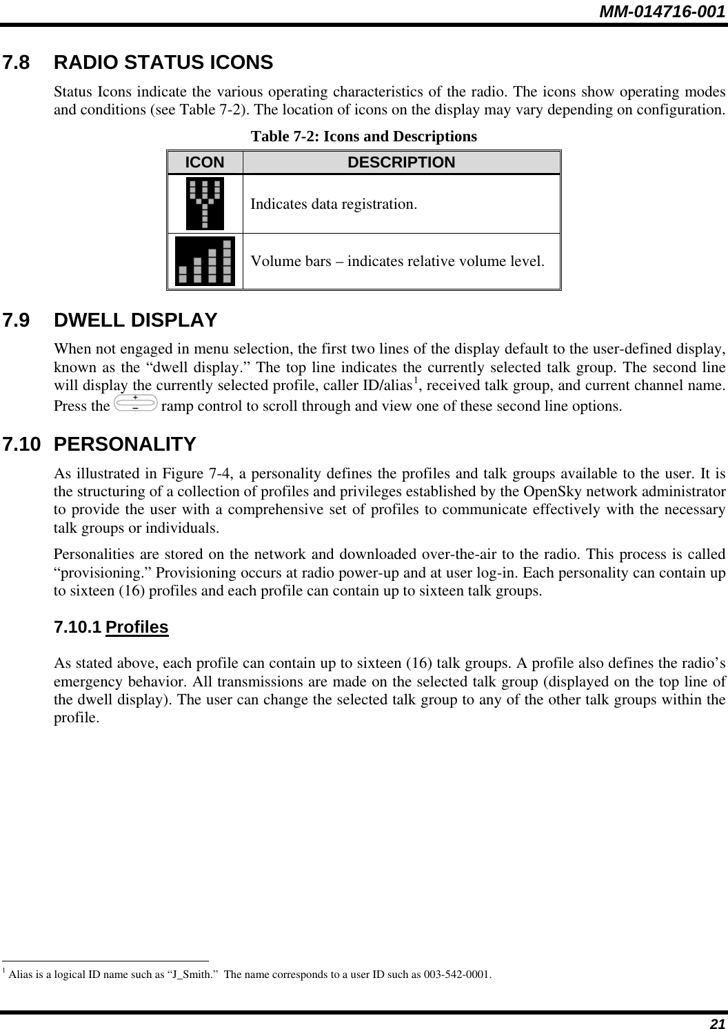
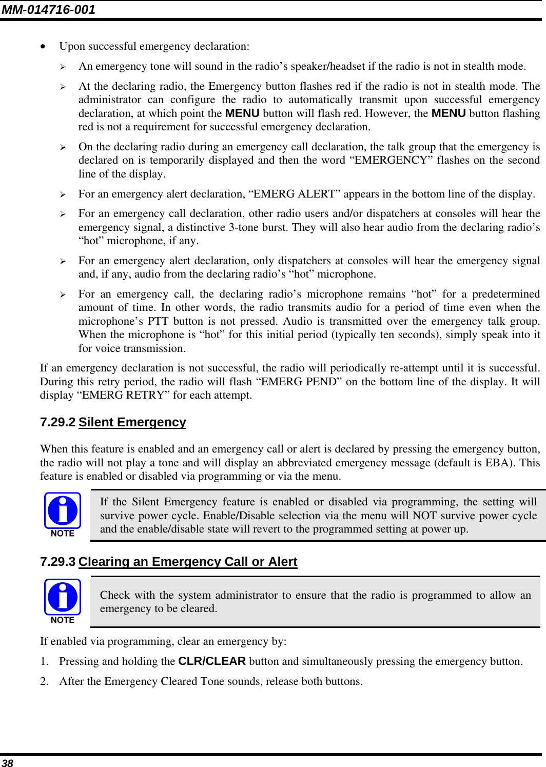
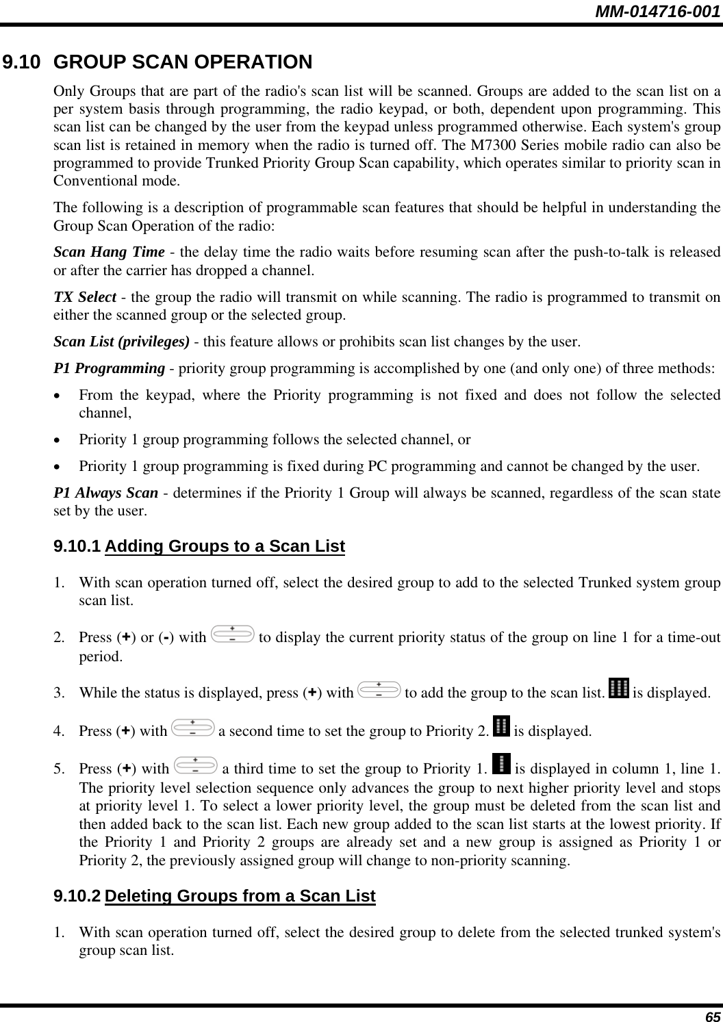
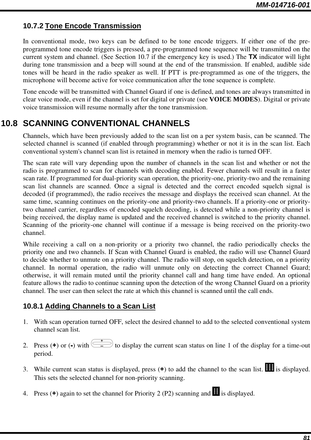
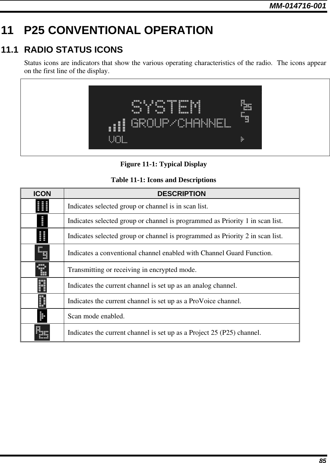
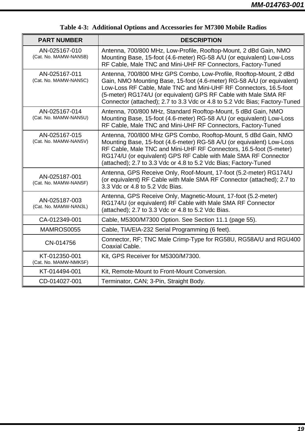
![MM-014716-001 64 9.9.2 ProScan The radio can be programmed for ProScan™ system scan operation for multi-site applications depending on the version of radio flash code. ProScan provides the radio with the ability to select a new system for the radio to communicate on, when the selected system drops below a predefined level. This is accomplished by enabling each radio to analyze the signal quality of its current control channel and compare it with the signal quality of the control channel for each site in its adjacency scan list. (The signal quality metric used for the ProScan algorithm is based on a combination of both Received Signal Strength Indicator [RSSI] and Control Channel Verification [CCV] measurements.) When the selected system’s signal quality level degrades below a pre-programmed level, the radio will begin to look for a better control channel. Once a control channel that exceeds the pre-programmed parameters is found, the radio will change to the new system and emit a tone. If the control channel is completely lost the radio, will enter Wide Area System Scanning and search the programmed adjacent systems until a suitable control channel is found. 9.9.3 Priority System Scan The radio can also be programmed for Priority System Scan. (To ensure that this feature operates correctly, the control channel of the priority system must be located on channel one unless you are using the ProScan algorithm.) The priority system is the desired or preferred system. While receiving the control channel of the selected system, the radio will periodically leave the selected system and search for the control channel of the priority system at a programmable rate. The programmable rate is defined by the value in the Priority Scan Time control, (unless the ProSound/ProScan algorithm is enabled as explained below). This priority scan timer is reset each time the PTT button is pressed or when a call is received. If the priority system control channel is found, or meets the predefined ProScan criteria, the radio will automatically switch to the priority system. 9.9.4 When Wide Area System Scan Is Enabled If the radio cannot find the control channel of the selected system and begins Wide Area System Scan (WA Scan), the radio will only scan for the priority system control channel if the priority system is in the WA Scan list. 9.9.5 When ProScan Is Enabled The radio monitors the priority system and will switch to the priority system if the priority system meets the criteria defined in the “ProSound/ProScan Options” dialog box. If ProScan is enabled, the rate at which the radio will scan for the priority system is defined by the System Sample Time control. 9.9.6 Menu Selection Press MENU and then use the ramp control to scroll through the selections until SYS SCAN is displayed. Then press MENU to toggle the System Scan state. The SYSC ON or SYSC OFF display message is displayed for two seconds to show the new state. 9.9.7 Pre-Programmed Keypad Key Press the pre-programmed key and the SYSC ON or SYSC OFF display message is displayed for two seconds to show the new state.](https://usermanual.wiki/HARRIS/TR-0051-E.Manual/User-Guide-949280-Page-65.png)


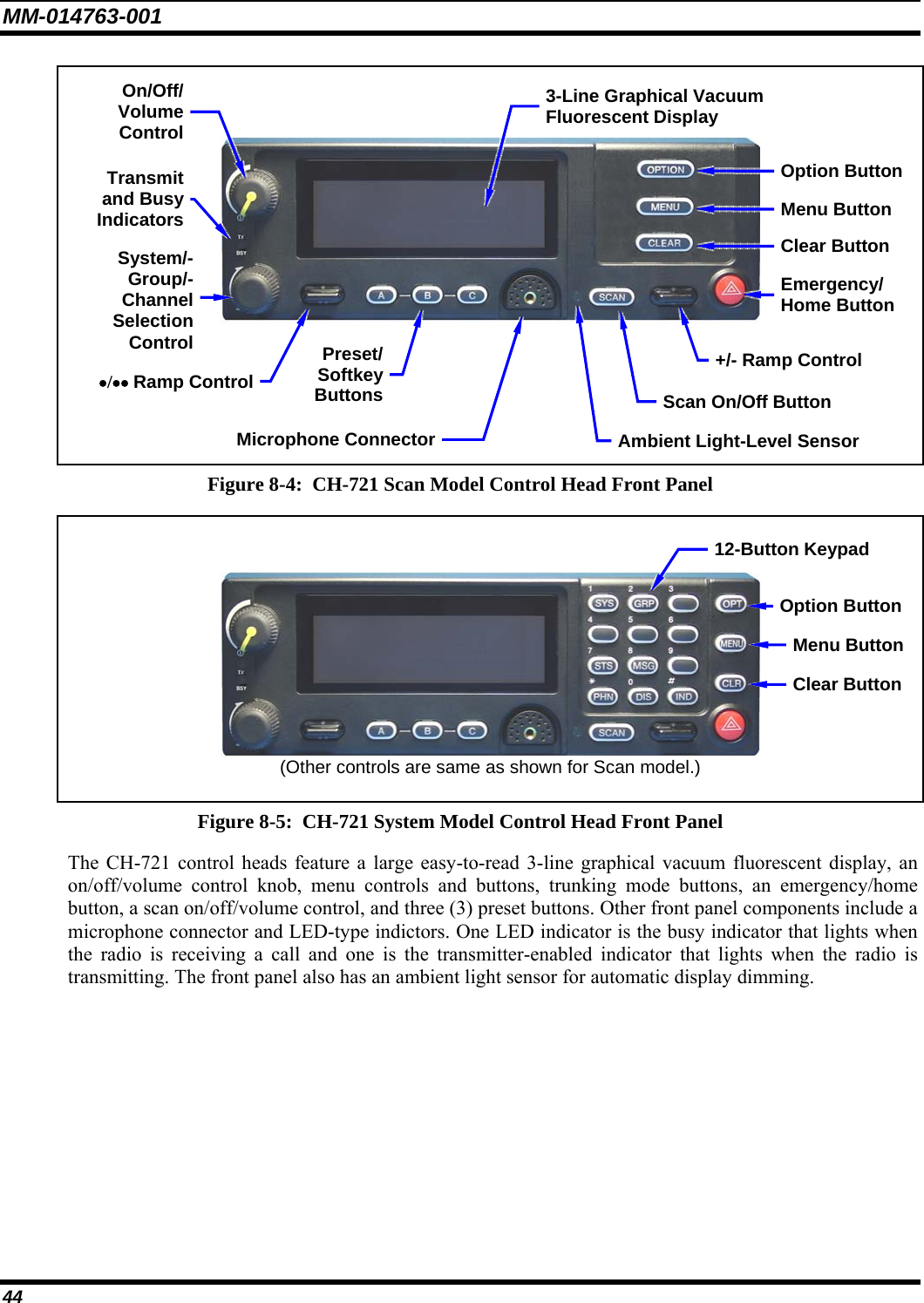
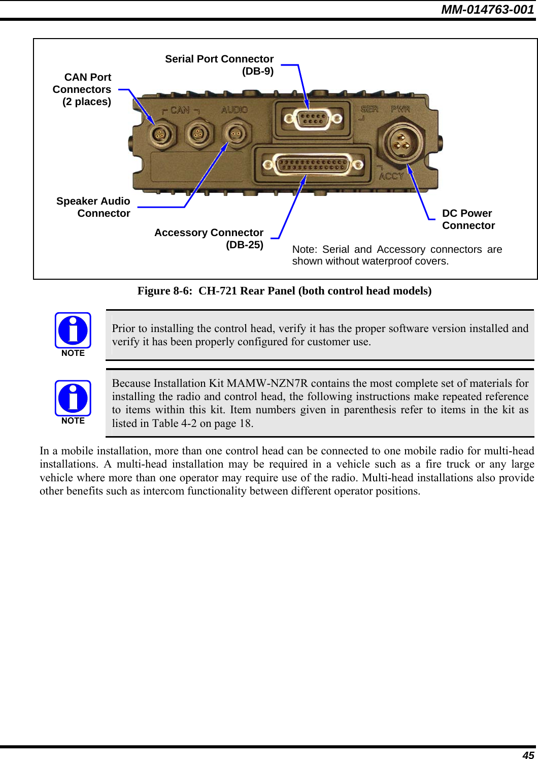
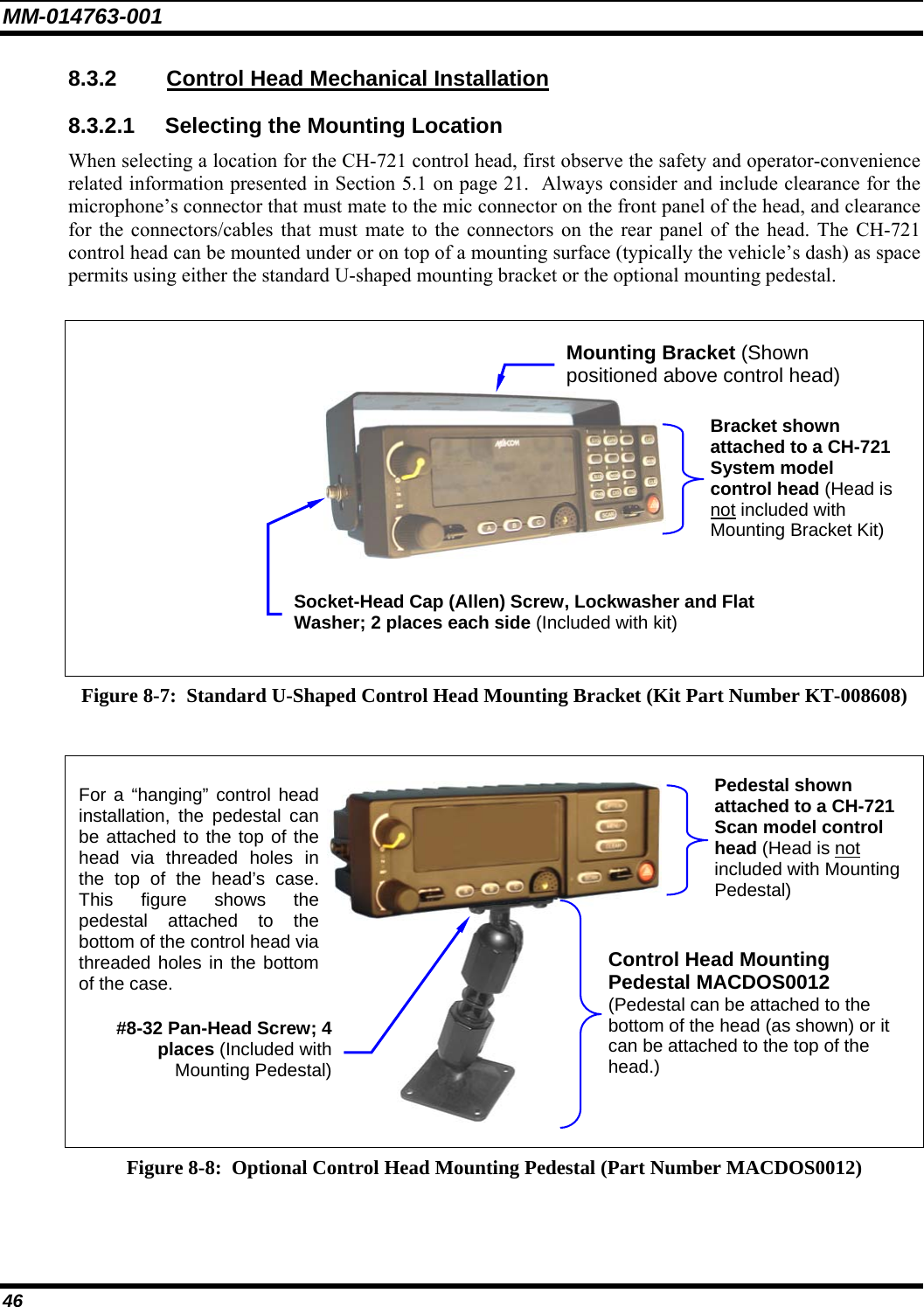
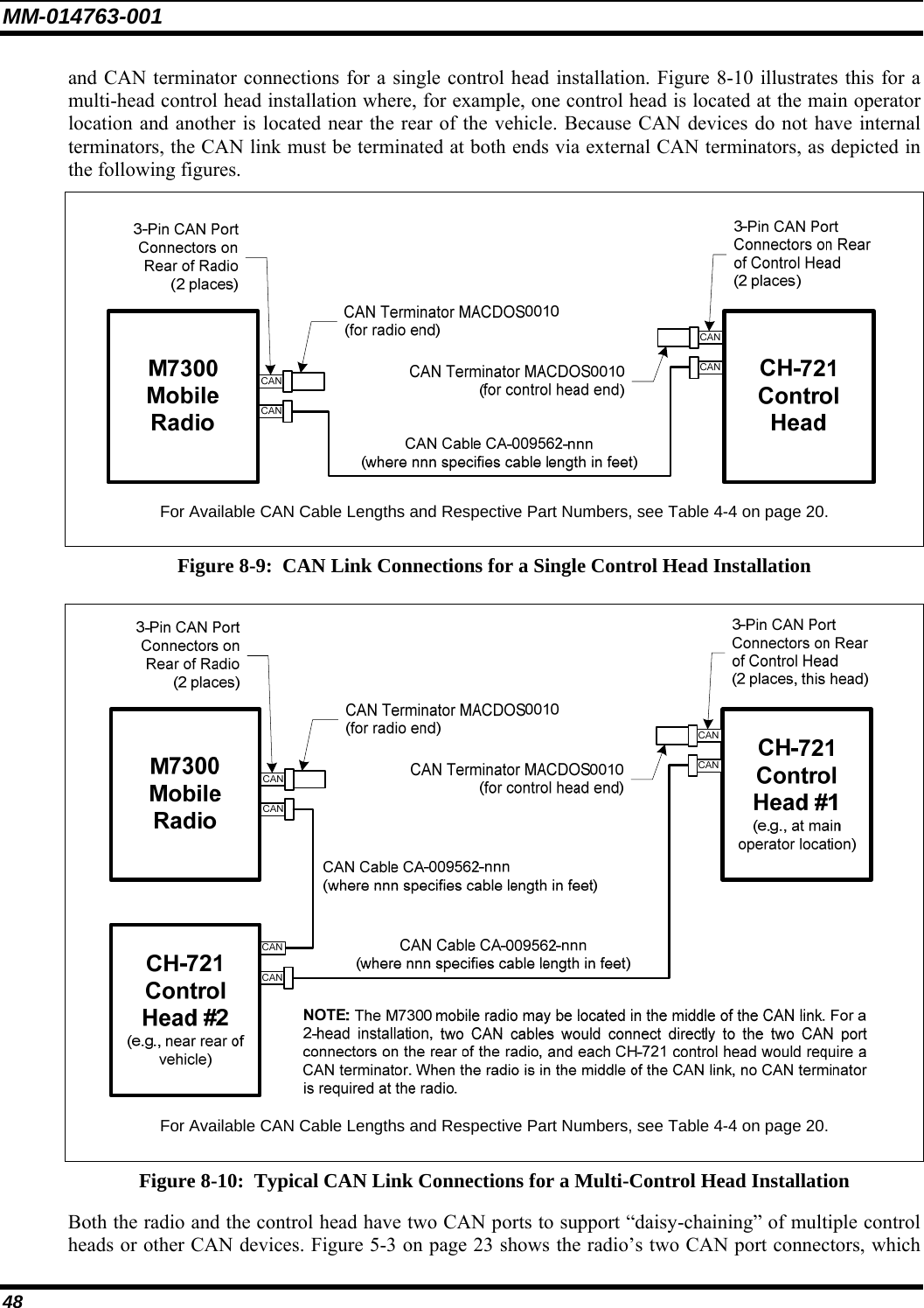
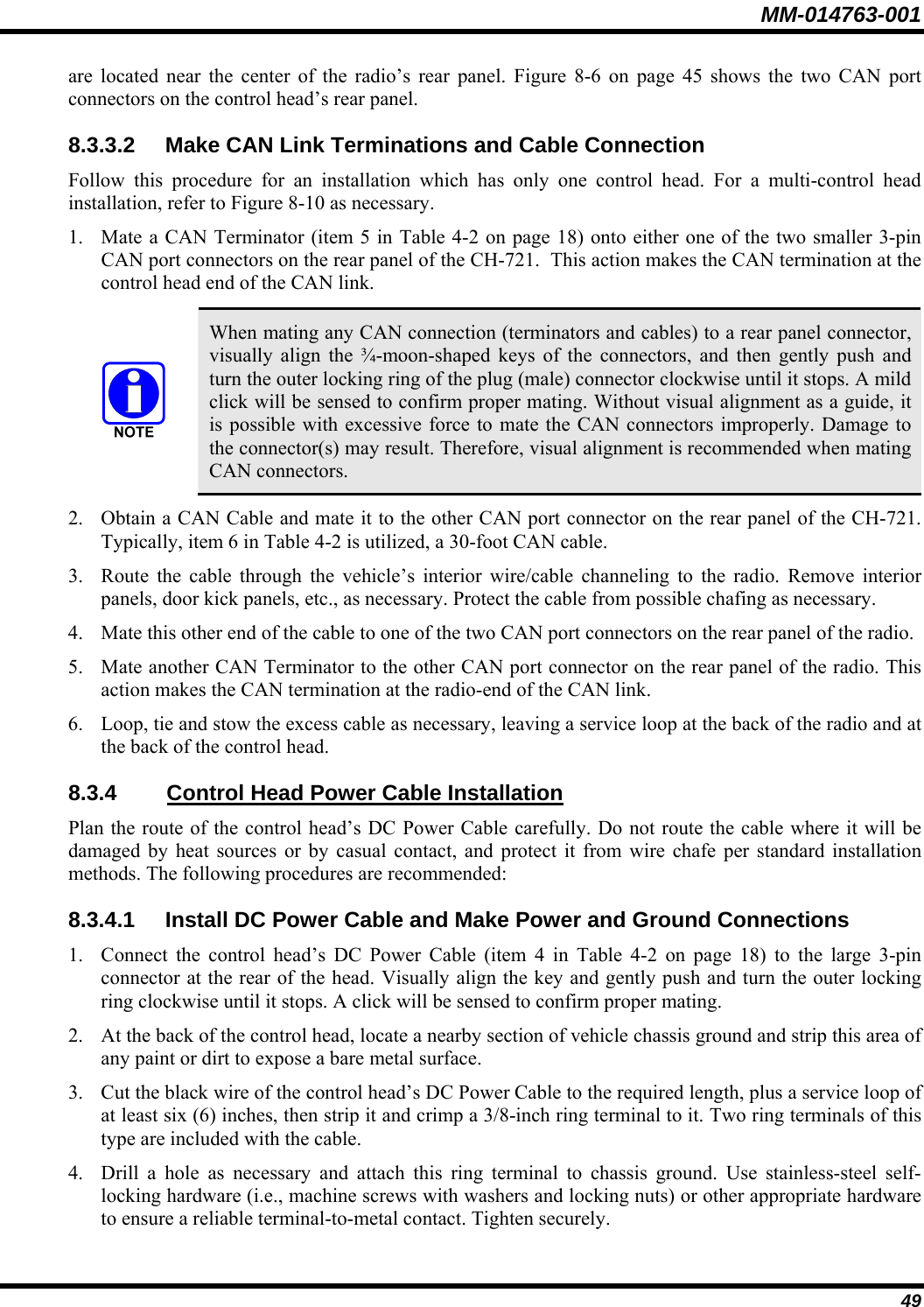
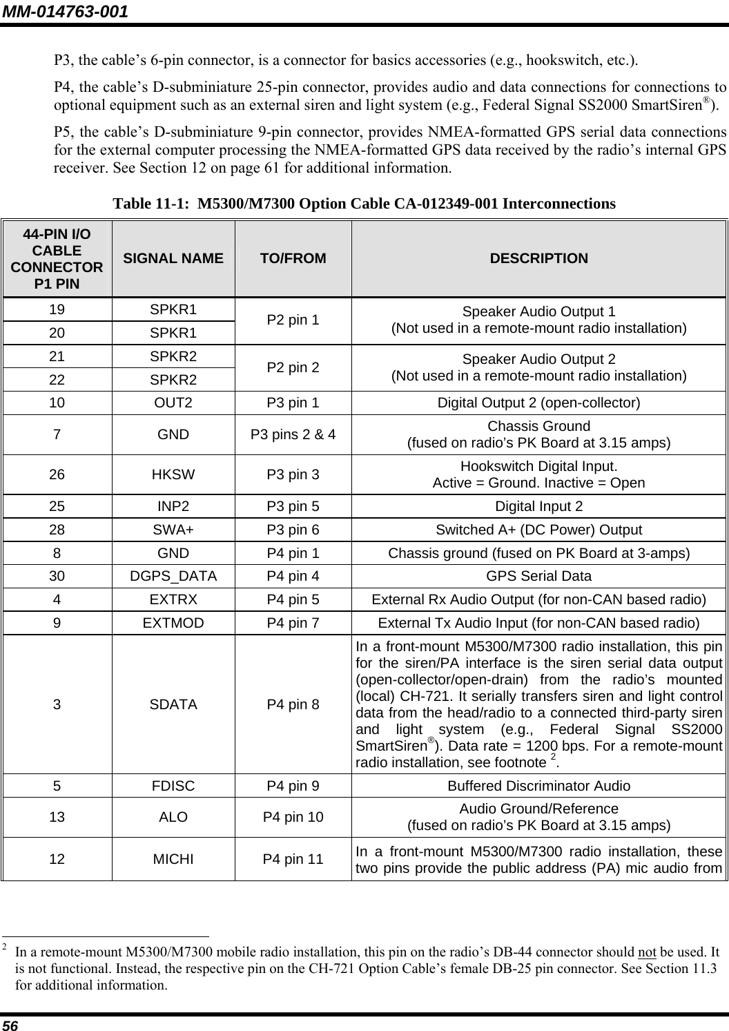
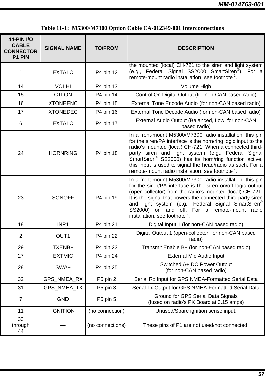
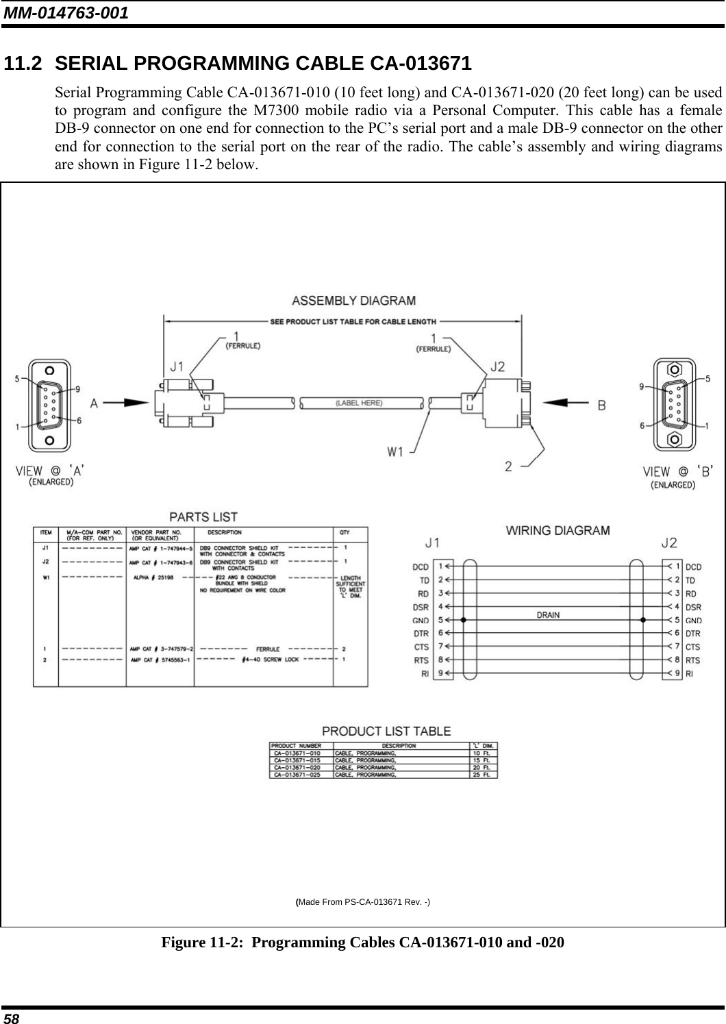
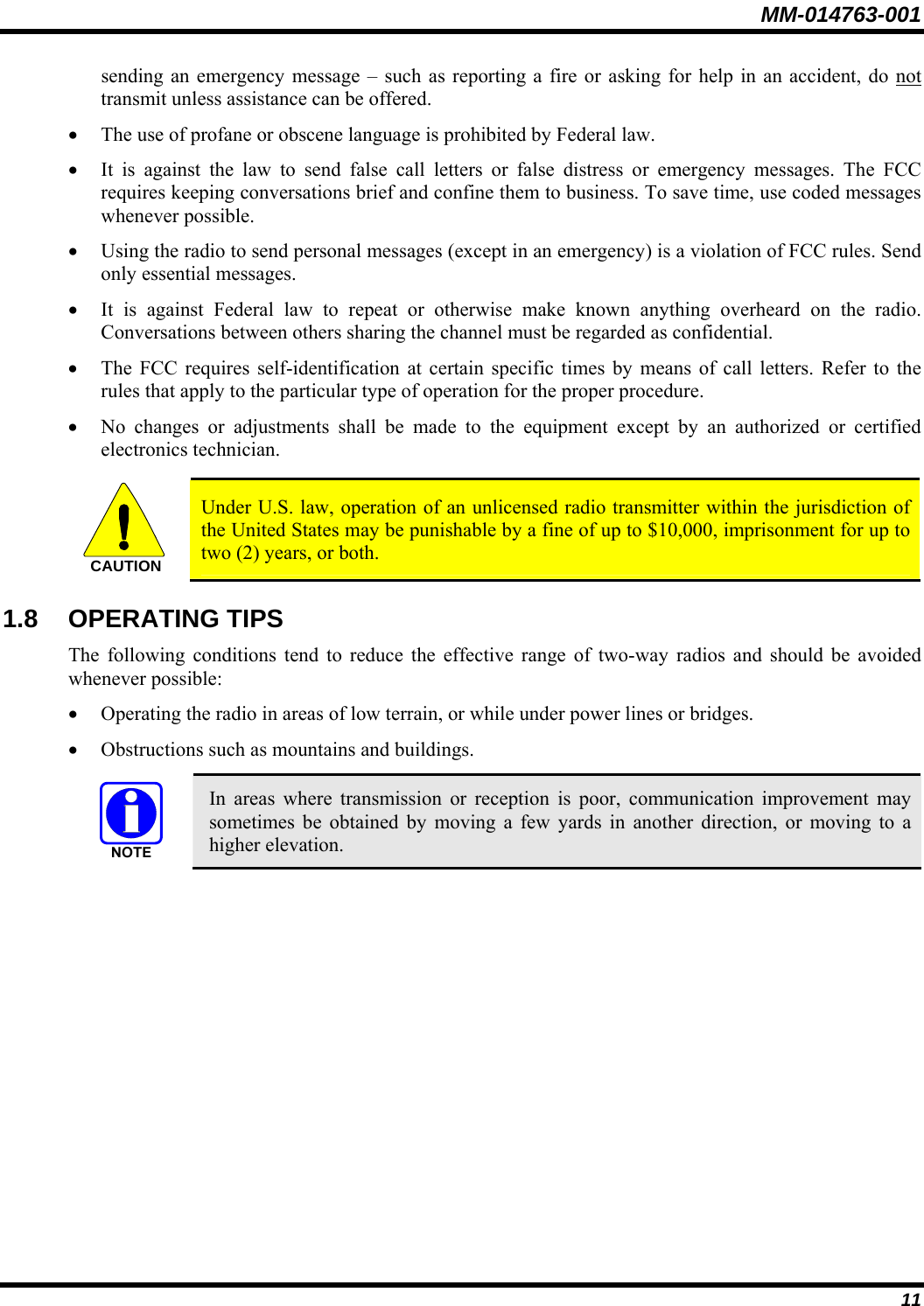
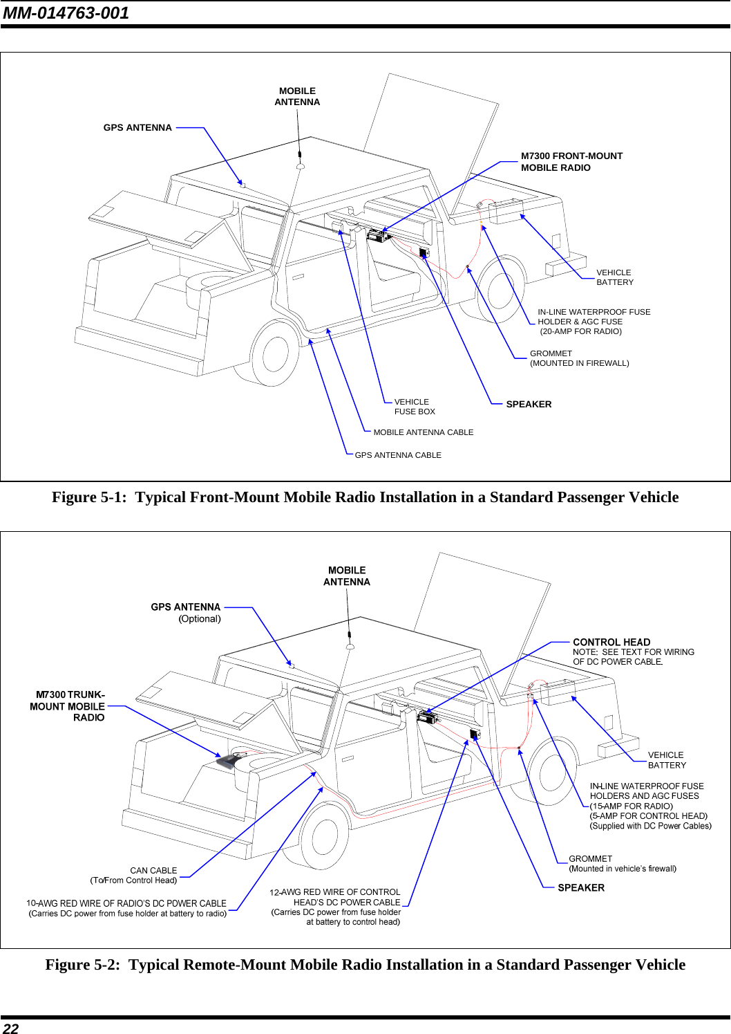
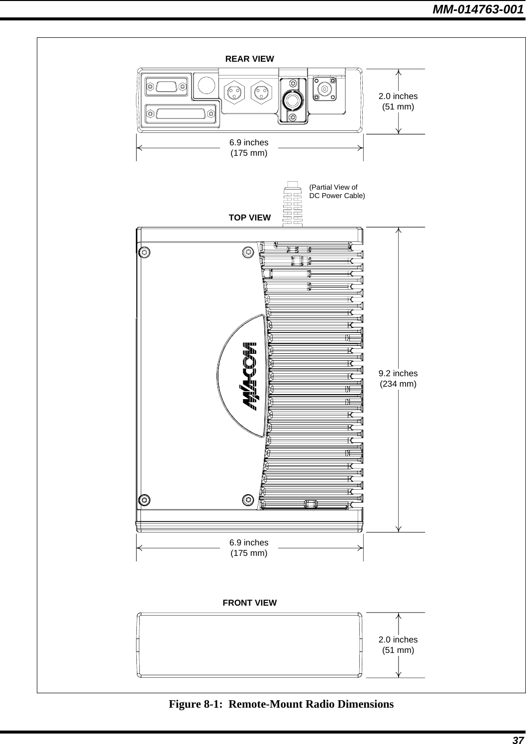
![MM-014763-001 5 FIGURES Page Figure 5-1: Typical Front-Mount Mobile Radio Installation in a Standard Passenger Vehicle ..........................22 Figure 5-2: Typical Remote-Mount Mobile Radio Installation in a Standard Passenger Vehicle....................... 22 Figure 5-3: M7300 Front-Mount and Remote-Mount Mobile Radios — Front and Rear Views........................ 23 Figure 6-1: Recommended Antenna Mounting Locations with Antenna Part Numbers.....................................25 Figure 6-2: Crimping Instructions for TNC RF Connector .................................................................................27 Figure 7-1: Front-Mount Mounting Bracket Kit KT101533V1 ..........................................................................30 Figure 7-2: Mounting Bracket FM101319V1 (Marked KTB0310) Dimensions [for Front-Mount M7300 Mobile Radio (Radio Not Shown)].............................................................................................. 31 Figure 8-1: Remote-Mount Radio Dimensions ...................................................................................................37 Figure 8-2: Remote-Mount Mounting Bracket Kit KT23117 .............................................................................38 Figure 8-3: Mounting Bracket FM103111V1 Dimensions [for Remote-Mount M7300 Mobile Radio (Radio Not Shown)].....................................................................................................................39 Figure 8-4: CH-721 Scan Model Control Head Front Panel ...............................................................................44 Figure 8-5: CH-721 System Model Control Head Front Panel ...........................................................................44 Figure 8-6: CH-721 Rear Panel (both control head models)............................................................................... 45 Figure 8-7: Standard U-Shaped Control Head Mounting Bracket (Kit Part Number KT-008608)..................... 46 Figure 8-8: Optional Control Head Mounting Pedestal (Part Number MACDOS0012).....................................46 Figure 8-9: CAN Link Connections for a Single Control Head Installation .......................................................48 Figure 8-10: Typical CAN Link Connections for a Multi-Control Head Installation .........................................48 Figure 10-1: Attaching the Microphone to the CH-721Control Head................................................................. 54 Figure 11-1: M5300/M7300 Option Cable CA-012349-001...............................................................................55 Figure 11-2: Programming Cables CA-013671-010 and -020 ............................................................................58 Figure 11-3: CH-721 Option Cable CA-011854-001..........................................................................................59 Figure 11-4: Programming Cable CA-104861 ....................................................................................................60 Figure 14-1: Wattmeter Connections for Antenna System Tests ........................................................................65 TABLES Page Table 1-1: Recommended Minimum Safe Lateral Distance from Transmitting Antenna......................................8 Table 4-1: Installation Kit MAMW-NZN6W for Front-Mount M7300 Mobile Radio.......................................17 Table 4-2: Installation Kit MAMW-NZN7R for Remote-Mount M7300 Mobile Radio with CH-721 Control Head................................................................................................................................18 Table 4-3: Additional Options and Accessories for M7300 Mobile Radios ....................................................... 18 Table 4-4: Additional Options and Accessories for CH-721 Control Heads.......................................................20 Table 11-1: M5300/M7300 Option Cable CA-012349-001 Interconnections.....................................................56 Table 14-1: Required Test Equipment ................................................................................................................64](https://usermanual.wiki/HARRIS/TR-0051-E.Manual/User-Guide-949280-Page-109.png)
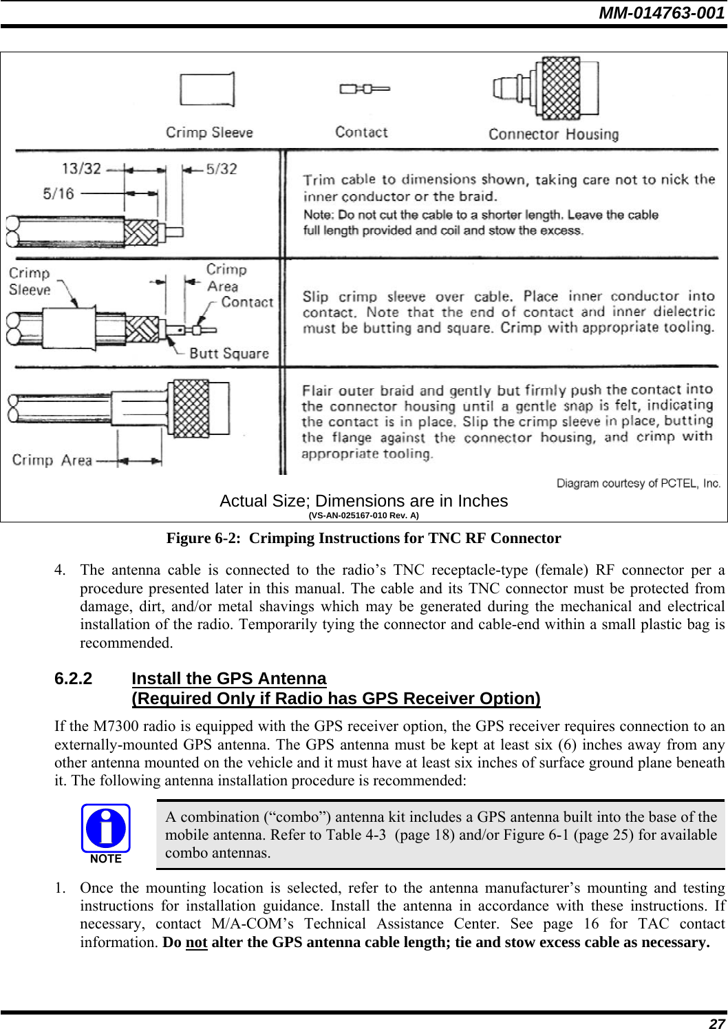
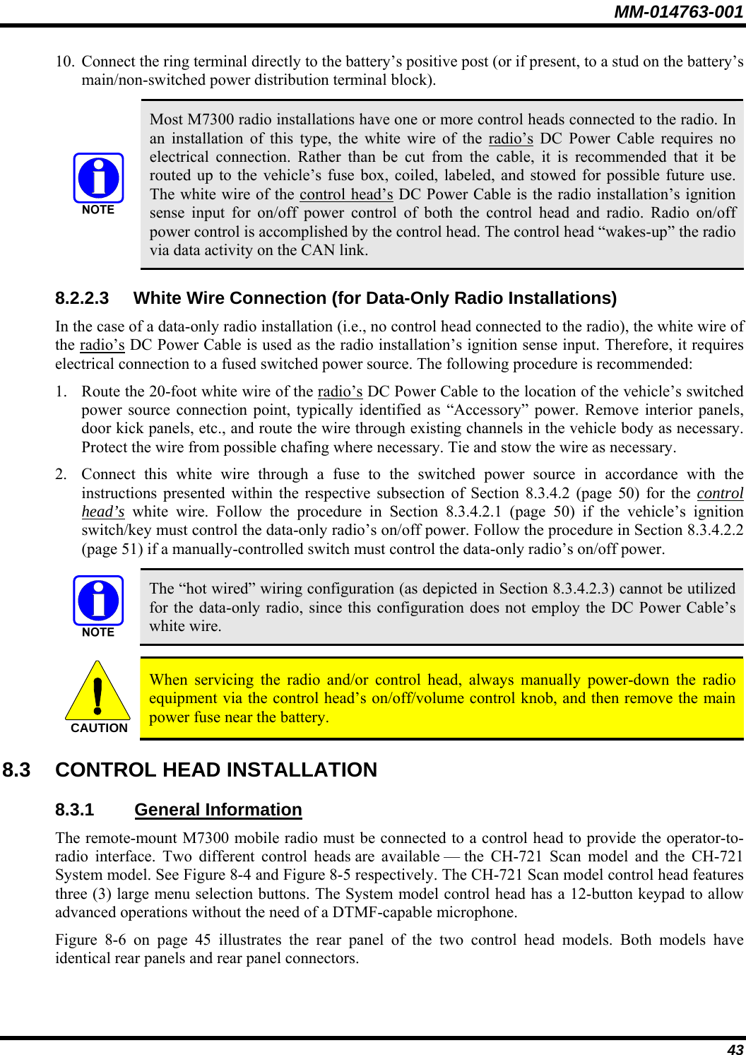
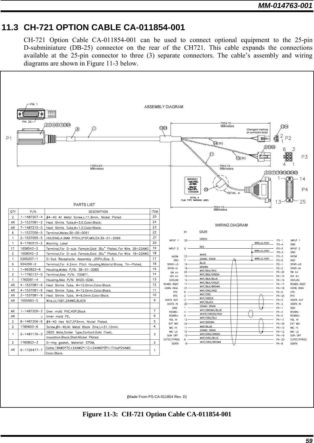
![MM-014763-001 31 TOP VIEW SIDE VIEW (Dimensions in Inches) FRONT/REAR VIEW (Dimensions in Inches) (Made From KBT0310B) Figure 7-2: Mounting Bracket FM101319V1 (Marked KTB0310) Dimensions [for Front-Mount M7300 Mobile Radio (Radio Not Shown)] 3. If the mounting surface is not flat (such as the top of a transmission hump), construct a suitable mounting wedge as necessary, and attach the wedge to the surface using an approved attachment method. Never mount the bracket directly to a non-flat surface. 4. On the mounting surface, mark the selected location for the bracket, and then remove the radio from the bracket. 5. Clean and remove any foreign material from the mounting surface. Bracket-To-Vehicle Screw Holes (11 places)Bracket-To-Radio Screw Holes(10 places,5 each side)](https://usermanual.wiki/HARRIS/TR-0051-E.Manual/User-Guide-949280-Page-135.png)

![MM-014763-001 39 5. Install and tighten the mounting screws/hardware. 6. Verify the bracket is firmly secured to the mounting surface. A secure mount prevents unreasonable vibration, which could damage the radio and/or cause its cable connections to loosen. TOP VIEW SIDE VIEW (Dimensions in Inches) FRONT VIEW (Dimensions in Inches) (Made From FM103111 Rev. B) Figure 8-3: Mounting Bracket FM103111V1 Dimensions [for Remote-Mount M7300 Mobile Radio (Radio Not Shown)] Bracket-To-Vehicle Screw Holes (4 places) Bracket-To-Radio Screw Holes(6 places,3 each side)Rear of Bracket Front of Bracket](https://usermanual.wiki/HARRIS/TR-0051-E.Manual/User-Guide-949280-Page-143.png)