HARRIS TR-0051-E M7300/M5300 Mobile Radio User Manual Manual
HARRIS CORPORATION M7300/M5300 Mobile Radio Manual
HARRIS >
Contents
- 1. Manual
- 2. Manual 1
- 3. Manual 2
- 4. Manual 3
Manual

Rhein Tech Laboratories, Inc. Client: M/A-COM, Inc.
360 Herndon Parkway Model: M7300/M5300 Mobile Radio
Suite 1400 FCC ID: OWDTR-0051-E/IC: 3636B-0051
Herndon, VA 20170 Standards: FCC Part 90/IC RSS-119
http://www.rheintech.com Report #: 2008095
Appendix L: Manual
Please refer to the following pages for the Operator’s Manual and the Installation Manual.
63 of 67

Operator’s Manual
MM-014716-001
May/08
M/A-COM
M7300 Series
Digital Mobile Radio

MM-014716-001
2
MANUAL REVISION HISTORY
REV DATE REASON FOR CHANGE
- May/08 Initial Release.
M/A-COM Technical Publications would particularly appreciate feedback on any errors found in this document and
suggestions on how the document could be improved. Submit your comments and suggestions to:
Tyco Electronics Wireless Systems Segment or fax your comments to: 1-434-455-6851
M/A-COM, Inc.
Technical Publications or e-mail us at: techpubs@tycoelectronics.com
221 Jefferson Ridge Parkway
Lynchburg, VA 24501
CREDITS
This device is made under license under one or more of the following US patents: 4,590,473; 4,636,791; 5,148,482;
5,185,796; 5,271,017; 5,377,229; 4,716,407; 4,972,460; 5,502,767; 5,146,497; 5,164,986; 5,185,795.
The voice coding technology embodied in this product is protected by intellectual property rights including patent rights,
copyrights, and trade secrets of Digital Voice Systems, Inc. The user of this technology is explicitly prohibited from
attempting to decompile, reverse engineer, or disassemble the Object Code, or in any other way convert the Object Code into
human-readable form.
EDACS and OpenSky are registered trademarks of M/A-COM, Inc. ProVoice is a trademark of M/A-COM
All other brand and product names are trademarks, registered trademarks or service marks of their respective holders.
NOTICE!
This product conforms to the European Union WEEE Directive 2002/96/EC. Do not dispose of this product in a
public landfill. Take it to a recycling center at the end of its life.
This manual covers M/A-COM products manufactured and sold by M/A-COM, Inc.
Repairs to this equipment should be made only by an authorized service technician or facility designated by the supplier. Any
repairs, alterations or substitutions of recommended parts made by the user to this equipment not approved by the
manufacturer could void the user's authority to operate the equipment in addition to the manufacturer's warranty.
This manual is published by M/A-COM, Inc., without any warranty. Improvements and changes to this manual necessitated
by typographical errors, inaccuracies of current information, or improvements to programs and/or equipment, may be made
by M/A-COM, Inc., at any time and without notice. Such changes will be incorporated into new editions of this manual. No
part of this manual may be reproduced or transmitted in any form or by any means, electronic or mechanical, including
photocopying and recording, for any purpose, without the express written permission of M/A-COM, Inc.
Copyright© 2008, M/A-COM, Inc. All rights reserved.

MM-014716-001
3
TABLE OF CONTENTS Page
1 SAFETY SYMBOL CONVENTION....................................................................................................9
2 RF ENERGY EXPOSURE INFORMATION ...................................................................................10
2.1 RF ENERGY EXPOSURE AWARENESS, CONTROL INFORMATION, AND OPERATION
INSTRUCTIONS FOR FCC OCCUPATIONAL USE REQUIREMENTS ..............................10
2.1.1 Federal Communications Commission Regulations......................................................10
2.2 COMPLIANCE WITH RF EXPOSURE STANDARDS...........................................................11
2.2.1 Mobile Antennas............................................................................................................11
2.2.2 Approved Accessories ...................................................................................................12
2.2.3 Contact Information.......................................................................................................12
3 OPERATION SAFETY RECOMMENDATIONS............................................................................13
3.1 TRANSMITTER HAZARDS.....................................................................................................13
3.2 SAFE DRIVING RECOMMENDATIONS................................................................................13
4 OPERATING RULES AND REGULATIONS..................................................................................14
4.1 OPERATING TIPS.....................................................................................................................14
5 PRODUCT DESCRIPTION................................................................................................................15
5.1 REMOTE CONTROL HEAD OPERATION.............................................................................15
6 CHANGE OPERATING MODE ........................................................................................................16
6.1 CHANGE FROM OTP MODE...................................................................................................16
6.2 CHANGE TO OTP MODE.........................................................................................................16
7 OPENSKY OPERATION....................................................................................................................17
7.1 CH721 FRONT PANEL COMPONENTS .................................................................................17
7.2 POWER UP AND VOLUME CONTROL .................................................................................18
7.2.1 Power Up.......................................................................................................................18
7.2.2 Volume Control.............................................................................................................19
7.3 SELF-TEST.................................................................................................................................19
7.4 LOGIN TO THE NETWORK ....................................................................................................19
7.5 LOG OFF THE NETWORK.......................................................................................................20
7.6 TURNING THE RADIO OFF....................................................................................................20
7.7 MENU DISPLAY AND CONTROL AREA..............................................................................20
7.8 RADIO STATUS ICONS...........................................................................................................21
7.9 DWELL DISPLAY.....................................................................................................................21
7.10 PERSONALITY .........................................................................................................................21
7.10.1 Profiles...........................................................................................................................21
7.10.2 Talk Groups...................................................................................................................22
7.11 ALERT TONES..........................................................................................................................23
7.12 BASIC MENU STRUCTURE....................................................................................................23
7.13 DUAL-TONE MULTI-FREQUENCY.......................................................................................26
7.14 KEYPAD COMMANDS (SYSTEM MODEL CONTROL HEAD)..........................................26
7.14.1 Password Entry..............................................................................................................26
7.14.2 DTMF Overdial.............................................................................................................27
7.15 CHANGING THE ACTIVE PROFILE......................................................................................27
7.16 CHECKING OR CHANGING THE SELECTED TALK GROUP............................................27
7.17 ADJUSTING DISPLAY AND BUTTON BACKLIGHT BRIGHTNESS.................................27

MM-014716-001
4
TABLE OF CONTENTS Page
7.18 STEALTH MODE ......................................................................................................................27
7.18.1 Enabling Stealth Mode ..................................................................................................28
7.18.2 Disabling Stealth Mode .................................................................................................28
7.19 ADJUSTING SIDE TONE AUDIO LEVEL..............................................................................28
7.20 CHANGE OPERATING MODE................................................................................................28
7.21 RECEIVING AND TRANSMITTING VOICE CALLS............................................................29
7.21.1 Receiving a Voice Call..................................................................................................29
7.21.2 Transmitting a Voice Call..............................................................................................29
7.22 ADJUSTING AUDIO TREBLE LEVEL ...................................................................................29
7.23 INTERCOM MODE ...................................................................................................................30
7.24 TALK GROUP LOCK OUT.......................................................................................................30
7.24.1 Lock Out a Talk Group..................................................................................................31
7.24.2 Unlock a Talk Group .....................................................................................................31
7.25 SCANNING ................................................................................................................................31
7.25.1 Checking or Changing Active Scan Mode ....................................................................32
7.25.2 Scanning Priority...........................................................................................................33
7.26 MAKING SELECTIVE CALLS ................................................................................................33
7.26.1 Manually Dialing a Selective Call (System Model Control Head)................................34
7.26.2 Speed Dialing a Selective Call ......................................................................................34
7.26.3 Receiving a Selective Call.............................................................................................34
7.26.4 Terminating a Selective Call .........................................................................................34
7.27 SELECTIVE ALERT..................................................................................................................35
7.27.1 Sending Selective Alert Messages.................................................................................35
7.27.2 Receiving Messages.......................................................................................................36
7.27.3 Defining Pre-Programmed Messages ............................................................................36
7.28 TELEPHONE INTERCONNECT CALLS (SYSTEM MODEL CONTROL HEAD) ..............36
7.28.1 Placing an Interconnect Call..........................................................................................36
7.28.2 Receiving an Interconnect Call......................................................................................37
7.29 EMERGENCY COMMUNICATIONS......................................................................................37
7.29.1 Declaring an Emergency Call or Alert ..........................................................................37
7.29.2 Silent Emergency...........................................................................................................38
7.29.3 Clearing an Emergency Call or Alert ............................................................................38
7.29.4 Receiving an Emergency Call .......................................................................................39
7.29.5 Dismissing an Emergency Call......................................................................................39
7.30 ENCRYPTION ...........................................................................................................................40
7.30.1 Automatic Encryption....................................................................................................40
7.30.2 Manual Encryption (System Model) .............................................................................40
7.31 PRESET BUTTONS...................................................................................................................41
7.32 DYNAMIC REGROUPING.......................................................................................................41
7.33 GPS COORDINATES ................................................................................................................42
8 P25/EDACS/CONVENTIONAL COMMON OPERATION ...........................................................43
8.1 CH721 FRONT PANEL COMPONENTS .................................................................................43
8.1.1 Primary Functions (Quick Access)................................................................................45
8.2 TURNING THE RADIO ON......................................................................................................45
8.3 SELECTION MODE RULES.....................................................................................................45
8.4 DIRECT ACCESS ......................................................................................................................46

MM-014716-001
5
TABLE OF CONTENTS Page
8.5 FEATURE ENCRYPTION DISPLAY.......................................................................................46
8.5.1 Serial Number ROM (12 Hex Digits)............................................................................47
8.5.2 Feature Encryption Data Stream....................................................................................47
8.5.3 Features Enabled............................................................................................................48
8.6 SYSTEM/GROUP/CHANNEL SELECTION............................................................................49
8.6.1 System Selection............................................................................................................49
8.6.2 Group and Channel Selection........................................................................................49
8.7 LAST SYSTEM/GROUP/CHANNEL RECALL.......................................................................50
8.8 DIGITAL VOICE OPERATION (PROVOICE) ........................................................................50
8.8.1 Voice Modes..................................................................................................................50
8.8.2 Clear Modes...................................................................................................................50
8.8.3 ProVoice Digital Mode..................................................................................................51
8.8.4 ProVoice Private Mode .................................................................................................51
8.8.5 Private Operation...........................................................................................................52
8.8.6 Conventional Operation.................................................................................................53
8.9 MACRO KEY OPERATION .....................................................................................................54
9 EDACS AND P25 TRUNKED OPERATION....................................................................................55
9.1 RADIO STATUS ICONS...........................................................................................................55
9.2 MESSAGES................................................................................................................................56
9.3 ALERT TONES..........................................................................................................................58
9.4 MENU.........................................................................................................................................59
9.5 RECEIVING A CALL................................................................................................................62
9.6 SENDING A CALL....................................................................................................................62
9.7 CONVENTIONAL FAILSOFT..................................................................................................62
9.8 EMERGENCY OPERATION ....................................................................................................63
9.8.1 Receiving an Emergency Call .......................................................................................63
9.8.2 Declaring an Emergency................................................................................................63
9.9 SYSTEM SCAN OPERATION..................................................................................................63
9.9.1 Wide Area System Scan ................................................................................................63
9.9.2 ProScan..........................................................................................................................64
9.9.3 Priority System Scan .....................................................................................................64
9.9.4 When Wide Area System Scan Is Enabled....................................................................64
9.9.5 When ProScan Is Enabled .............................................................................................64
9.9.6 Menu Selection..............................................................................................................64
9.9.7 Pre-Programmed Keypad Key.......................................................................................64
9.10 GROUP SCAN OPERATION....................................................................................................65
9.10.1 Adding Groups to a Scan List........................................................................................65
9.10.2 Deleting Groups from a Scan List .................................................................................65
9.10.3 Nuisance Delete.............................................................................................................66
9.10.4 Turning Scan On............................................................................................................66
9.10.5 Priority Group Scanning................................................................................................66
9.10.6 Turning Scan Off...........................................................................................................66
9.11 INDIVIDUAL CALLS ...............................................................................................................67
9.11.1 Receiving and Responding to an Individual Call ..........................................................67
9.11.2 Call Storage Lists...........................................................................................................67
9.11.3 Sending an Individual Call ............................................................................................68

MM-014716-001
6
TABLE OF CONTENTS Page
9.12 SCAT OPERATION...................................................................................................................68
9.13 TELEPHONE INTERCONNECT CALLS.................................................................................69
9.13.1 Receiving a Telephone Interconnect Call (Trunked Mode Only) .................................69
9.13.2 Sending a Telephone Interconnect Call (Trunked Mode Only).....................................69
9.13.3 DTMF Overdial/Conventional Mode Telephone Interconnect......................................69
9.13.4 Programmable Entries ...................................................................................................70
9.14 MOBILE DATA .........................................................................................................................70
9.14.1 Displays .........................................................................................................................71
9.14.2 DATA OFF Operation...................................................................................................71
9.14.3 DATA ON Operation ....................................................................................................71
9.14.4 Exiting Data Calls..........................................................................................................71
9.14.5 Scan Lockout Mode.......................................................................................................72
9.14.6 Data Lockout Mode.......................................................................................................72
9.15 STATUS/MESSAGE OPERATION ..........................................................................................72
9.15.1 Status Operation ............................................................................................................73
9.15.2 Message Operation ........................................................................................................73
9.16 EDACS CONVENTIONAL P1 SCAN ......................................................................................73
9.17 DYNAMIC REGROUP OPERATION.......................................................................................74
9.17.1 Emergency Operation....................................................................................................74
9.18 PAGE (P25 TRUNKED ONLY) ................................................................................................74
10 CONVENTIONAL OPERATION......................................................................................................75
10.1 RADIO STATUS ICONS...........................................................................................................75
10.2 MESSAGES................................................................................................................................75
10.3 ALERT TONES..........................................................................................................................77
10.4 MENU.........................................................................................................................................77
10.5 RECEIVING A CALL................................................................................................................79
10.6 SENDING A CALL....................................................................................................................80
10.7 EMERGENCY OPERATION ....................................................................................................80
10.7.1 Using 5-Tone Signaling to Declare an Emergency .......................................................80
10.7.2 Tone Encode Transmission............................................................................................81
10.8 SCANNING CONVENTIONAL CHANNELS .........................................................................81
10.8.1 Adding Channels to a Scan List.....................................................................................81
10.8.2 Deleting Channels From A Scan List............................................................................82
10.8.3 Nuisance Delete.............................................................................................................82
10.9 TURNING SCAN ON ................................................................................................................82
10.10 TURNING SCAN OFF...............................................................................................................82
10.11 SQUELCH ADJUST...................................................................................................................83
10.11.1 Menu Selection..............................................................................................................83
10.11.2 Pre-Programmed Keypad Key.......................................................................................83
10.12 TYPE 99 DECODE.....................................................................................................................83
10.12.1 Menu Selection..............................................................................................................84
10.12.2 Pre-Programmed Keypad Key.......................................................................................84
10.13 DIRECT MODE OPERATION..................................................................................................84
11 P25 CONVENTIONAL OPERATION...............................................................................................85
11.1 RADIO STATUS ICONS...........................................................................................................85

MM-014716-001
7
TABLE OF CONTENTS Page
11.2 MESSAGES................................................................................................................................86
11.3 ALERT TONES..........................................................................................................................87
11.4 MENU.........................................................................................................................................88
11.5 GROUP CALLS IN P25 MODE ................................................................................................90
11.5.1 Transmitting a Group Call.............................................................................................90
11.5.2 Receiving a Group Call .................................................................................................90
11.6 INDIVIDUAL CALLS IN P25 MODE ......................................................................................91
11.6.1 Transmitting an Individual Call.....................................................................................91
11.6.2 Receiving an Individual Call .........................................................................................91
11.7 EMERGENCY GROUP CALLS IN P25 MODE.......................................................................91
11.7.1 Declaring an Emergency Group Call.............................................................................91
11.7.2 Receiving an Emergency Group Call ............................................................................92
12 BASIC TROUBLESHOOTING..........................................................................................................93
13 TECHNICAL ASSISTANCE..............................................................................................................95
14 KEYPAD REMAPPING......................................................................................................................96
15 RADIO SETUP.....................................................................................................................................97
16 WARRANTY ......................................................................................................................................101

MM-014716-001
8
TABLE OF CONTENTS Page
FIGURES
Figure 7-1: System Model.......................................................................................................................17
Figure 7-2: Scan Model...........................................................................................................................17
Figure 7-3: Typical Display.....................................................................................................................20
Figure 7-4: Personality Structure Example .............................................................................................22
Figure 8-1: System Model.......................................................................................................................43
Figure 8-2: Scan Model...........................................................................................................................43
Figure 9-1: Typical Display.....................................................................................................................55
Figure 10-1: Typical Display...................................................................................................................75
Figure 11-1: Typical Display...................................................................................................................85
TABLES
Table 2-1: Rated Power and Recommended Minimum Safe Lateral Distance.......................................11
Table 7-1: Front Panel Default Controls and Functions..........................................................................18
Table 7-2: Icons and Descriptions...........................................................................................................21
Table 7-3: M7300 OpenSky Mode Alert Tones......................................................................................23
Table 7-4: Basic Menu Structure.............................................................................................................24
Table 7-5: Keypad Function Commands.................................................................................................26
Table 7-6: Scan Modes............................................................................................................................32
Table 7-7: Status of Selective Alert.........................................................................................................36
Table 8-1: Front Panel Default Controls and Functions..........................................................................44
Table 8-2: Available Feature Numbers ...................................................................................................48
Table 8-3: Transmit/Receive Mode Compatibility for ProVoice Operation..........................................50
Table 8-4: Current Cryptographic Key Display ......................................................................................52
Table 9-1: Icons and Descriptions...........................................................................................................55
Table 9-2: Display Messages...................................................................................................................56
Table 9-3: Alert Tones.............................................................................................................................58
Table 9-4: Menu Item Information..........................................................................................................60
Table 10-1: Icons and Descriptions.........................................................................................................75
Table 10-2: Display Messages.................................................................................................................75
Table 10-3: M7300 EDACS Mode Alert Tones......................................................................................77
Table 10-4: Menu Item Information........................................................................................................78
Table 11-1: Icons and Descriptions.........................................................................................................85
Table 11-2: Display Messages.................................................................................................................86
Table 11-3: M7300 EDACS Mode Alert Tones......................................................................................87
Table 11-4: Menu Item Information........................................................................................................88
Table 12-1: Basic Troubleshooting .........................................................................................................93
MM-014716-001
9
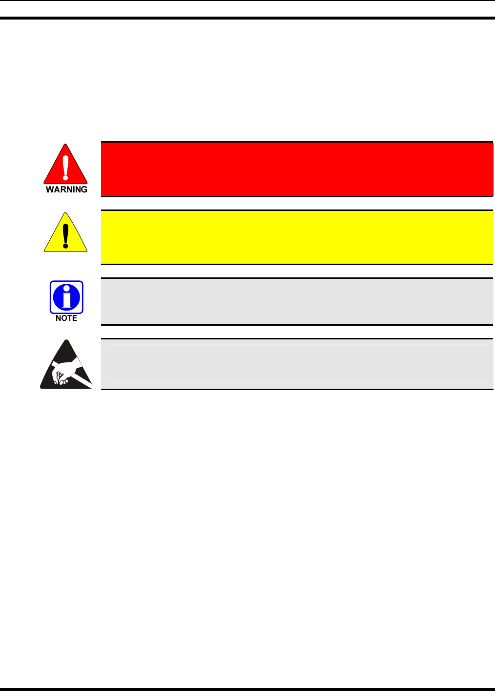
1 SAFETY SYMBOL CONVENTION
The following conventions are used throughout this manual to alert the user to general safety precautions
that must be observed during all phases of operation, service, and repair of this product. Failure to comply
with these precautions or with specific warnings elsewhere in this manual violates safety standards of
design, manufacture, and intended use of the product. M/A-COM, Inc. assumes no liability for the
customer’s failure to comply with these standards.
The WARNING symbol calls attention to a procedure, practice, or the like, which,
if not correctly performed or adhered to, could result in personal injury. Do not
proceed beyond a WARNING symbol until the conditions identified are fully
understood or met.
CAUTION
The CAUTION symbol calls attention to an operating procedure, practice, or the like,
which, if not performed correctly or adhered to, could result in a risk of danger, damage
to the equipment, or severely degrade the equipment performance.
The NOTE symbol calls attention to supplemental information, which may improve
system performance or clarify a process or procedure.
The ESD symbol calls attention to procedures, practices, or the like, which could expose
equipment to the effects of Electro-Static Discharge. Proper precautions must be taken
to prevent ESD when handling circuit modules.
MM-014716-001
10
2 RF ENERGY EXPOSURE INFORMATION
2.1 RF ENERGY EXPOSURE AWARENESS, CONTROL INFORMATION,
AND OPERATION INSTRUCTIONS FOR FCC OCCUPATIONAL USE
REQUIREMENTS
Before using your mobile two-way radio, read this important RF energy awareness and control
information and operational instructions to ensure compliance with the FCC’s RF exposure
guidelines.
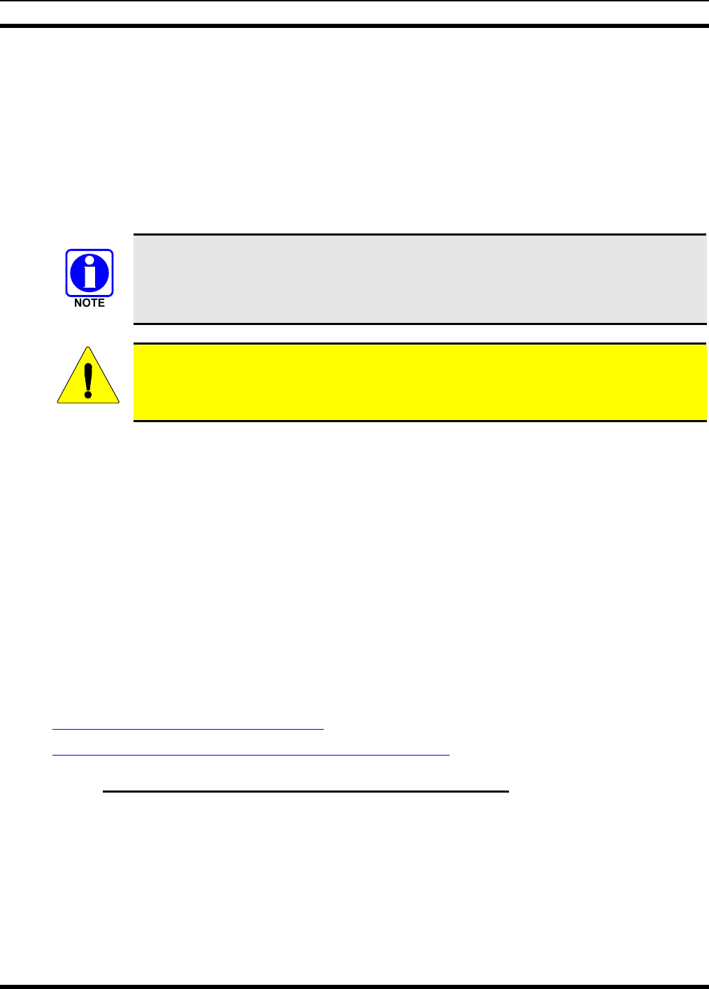
This radio is intended for use in occupational/controlled conditions, where users have full
knowledge of their exposure and can exercise control over their exposure to meet FCC
limits. This radio device is NOT authorized for general population, consumer, or any
other use.
CAUTION
Changes or modifications not expressly approved by M/A-COM, Inc. could void the
user's authority to operate the equipment.
This two-way radio uses electromagnetic energy in the radio frequency (RF) spectrum to provide
communications between two or more users over a distance. It uses RF energy or radio waves to send and
receive calls. RF energy is one form of electromagnetic energy. Other forms include, but are not limited
to, electric power, sunlight, and x-rays. RF energy, however, should not be confused with these other
forms of electromagnetic energy, which, when used improperly, can cause biological damage. Very high
levels of x-rays, for example, can damage tissues and genetic material.
Experts in science, engineering, medicine, health, and industry work with organizations to develop
standards for exposure to RF energy. These standards provide recommended levels of RF exposure for
both workers and the general public. These recommended RF exposure levels include substantial margins
of protection. All two-way radios marketed in North America are designed, manufactured, and tested to
ensure they meet government established RF exposure levels. In addition, manufacturers also recommend
specific operating instructions to users of two-way radios. These instructions are important because they
inform users about RF energy exposure and provide simple procedures on how to control it. Please refer
to the following websites for more information on what RF energy exposure is and how to control your
exposure to assure compliance with established RF exposure limits.
http://www.fcc.gov/oet/rfsafety/rf-faqs.html
http://www.osha.gov./SLTC/radiofrequencyradiation/index.html
2.1.1 Federal Communications Commission Regulations
Your M/A COM, Inc. M7300 mobile two-way radio is designed and tested to comply with the FCC RF
energy exposure limits for mobile two-way radios before it can be marketed in the United States. When
two-way radios are used as a consequence of employment, the FCC requires users to be fully aware of
and able to control their exposure to meet occupational requirements. Exposure awareness can be
facilitated by the use of a label directing users to specific user awareness information. Your M/A COM,
Inc. M7300 two-way radio has an RF exposure product label. Also, your M7300 Installation and
Operator’s Manuals include information and operating instructions required to control your RF exposure
and to satisfy compliance requirements.
MM-014716-001
11
2.2 COMPLIANCE WITH RF EXPOSURE STANDARDS
Your MA/COM, Inc. M7300 mobile two-way radio is designed and tested to comply with a number of
national and international standards and guidelines (listed below) regarding human exposure to RF
electromagnetic energy. This radio complies with the IEEE and ICNIRP exposure limits for
occupational/controlled RF exposure environment at duty factors of up to 50% talk-50% listen and is
authorized by the FCC for occupational use. In terms of measuring RF energy for compliance with the
FCC exposure guidelines, your radio antenna radiates measurable RF energy only while it is transmitting
(talking), not when it is receiving (listening) or in standby mode.
Your M/A COM, Inc. M7300 mobile two-way radio complies with the following RF energy exposure
standards and guidelines:
• United States Federal Communications Commission (FCC), Code of Federal Regulations; 47 CFR §§
2 sub-part J.
• American National Standards Institute (ANSI)/Institute of Electrical and Electronic Engineers (IEEE)
C95.1-2005.
• Institute of Electrical and Electronic Engineers (IEEE) C95.1-2005.
• IC standard RSS-102, Issue 2, 2005: “Spectrum Management and Telecommunications Radio
Standards Specification. Radiofrequency Exposure Compliance of Radiocommunication Apparatus
(All Frequency Bands).
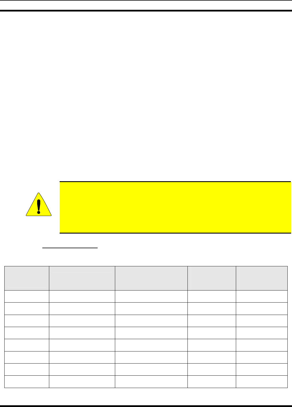
CAUTION
Table 2-1 lists the recommended minimum lateral distance for a controlled environment
and for unaware bystanders in an uncontrolled environment, from transmitting types of
antennas (i.e., monopoles over a ground plane, or dipoles) at rated radio power for
mobile radios installed in a vehicle. Transmit only when unaware bystanders are at least
the uncontrolled recommended minimum lateral distance away from the transmitting
antenna.
2.2.1 Mobile Antennas
Table 2-1: Rated Power and Recommended Minimum Safe Lateral Distance
MOBILE RADIO
FREQUENCY
SPLIT
ANTENNA PART
NUMBER DESCRIPTION
RSAFE
CONTROLLED
ENVIRONMENT
(CM)
RSAFE
UNCONTROLLED
ENVIRONMENT
(CM)
700/800 MHz AN-025167-002 Dual Band 700/800,
Elevated Feed, Roof Mount 28 69
700/800 MHz AN-025167-005 Combined GPS/700/800,
Elevated Feed, Roof Mount 28 69
700/800 MHz AN-025167-015 Combined GPS/764-870,
Roof Mount 39 87
700/800 MHz AN-025167-010 Dual Band 700/800, Low
Profile, Roof Mount 28 69
700/800 MHz AN-025167-006 Dual Band 700/800,
Magnetic Mount 29 72
700/800 MHz AN-025167-011 Combined GPS/700/800,
Low Profile, Roof Mount 28 69
700/800 MHz AN-025167-001 Dual Band 700/800, Roof
Mount 28 69
700/800 MHz AN-025167-004 Combined GPS/764-870,
Roof Mount 28 69

MM-014716-001
12
MOBILE RADIO
FREQUENCY
SPLIT
ANTENNA PART
NUMBER DESCRIPTION
RSAFE
CONTROLLED
ENVIRONMENT
(CM)
RSAFE
UNCONTROLLED
ENVIRONMENT
(CM)
700/800 MHz AN-025167-014 Dual Band 764-870, Roof
Mount 39 87
Install the radio’s antenna (refer to Table 2-1 for applicable antenna part numbers) in the center of the
vehicle’s roof. These mobile antenna installation guidelines are limited to metal body motor vehicles or
vehicles with appropriate ground planes. The antenna installation should additionally be in accordance
with the following:
• The requirements of the antenna manufacturer/supplier included with the antenna.
• Instructions in the M7300 Radio Installation Manual, including minimum antenna cable lengths.
• The installation manual providing specific information of how to install the antennas to facilitate
recommended operating distances to all potentially exposed persons.
Use only the M/A-COM approved/supplied antenna(s) or approved replacement antenna. Unauthorized
antennas, modifications, or attachments could damage the radio and may violate FCC regulations.
2.2.2 Approved Accessories
This radio has been tested and meets the FCC RF guidelines when used with the M/A-COM accessories
supplied or designated for use with this product. Use of other accessories may not ensure compliance with
the FCC’s RF exposure guidelines, and may violate FCC regulations.
For a list of M/A-COM approved accessories refer to the product manuals, M/A-COM’s Products and
Services Catalog, or contact M/A-COM at 1-800-368-3277.
2.2.3 Contact Information
For additional information on exposure requirements or other information, contact M/A-COM, Inc. at
1-800-528-7711 or at http://www.macom-wireless.com.

MM-014716-001
13
3 OPERATION SAFETY RECOMMENDATIONS
3.1 TRANSMITTER HAZARDS
The operator of any mobile radio should be aware of certain hazards common to
the operation of vehicular radio transmitters. A list of several possible hazards is
given:
• Explosive Atmospheres – Just as it is dangerous to fuel a vehicle with the motor running, similar
hazards exist when operating a mobile radio. Be sure to turn the radio off while fueling a vehicle. Do
not carry containers of fuel in the trunk of a vehicle if the radio is mounted in the trunk.
Areas with potentially explosive atmosphere are often, but not always, clearly marked. Turn OFF
your radio when in any area with a potentially explosive atmosphere. It is rare, but not impossible that
the radio or its accessories could generate sparks.
• Interference to Vehicular Electronics Systems – Electronic fuel injection systems, electronic anti-
skid braking systems, electronic cruise control systems, etc., are typical electronic systems that can
malfunction due to the lack of protection from radio frequency energy present when transmitting. If
the vehicle contains such equipment, consult the dealer and enlist their aid in determining the
expected performance of electronic circuits when the radio is transmitting.
• Electric Blasting Caps – To prevent accidental detonation of electric blasting caps, DO NOT use
two-way radios within 1000 feet of blasting operations. Always obey the “Turn off Two-Way
Radios” signs posted where electric blasting caps are being used. (OSHA Standard: 1926-900)
• Liquefied Petroleum (LP) Gas Powered Vehicles – Mobile radio installations in vehicles powered
by liquefied petroleum gas with the LP gas container in the trunk or other sealed-off space within the
interior of the vehicle must conform to the National Fire Protection Association standard NFPA 58
requiring:
¾ The LP gas container and its fittings.
¾ Outside filling connections shall be used for the LP gas container.
¾ The LP gas container shall be vented to the outside of the vehicle.
3.2 SAFE DRIVING RECOMMENDATIONS
(Recommended by AAA)
• Read the literature on the safe operation of the radio.
• Keep both hands on the steering wheel and the microphone in its hanger whenever the vehicle is in
motion.
• Place calls only when the vehicle is stopped.
• When talking from a moving vehicle is unavoidable, drive in the slower lane. Keep conversations
brief.
• If a conversation requires taking notes or complex thought, stop the vehicle in a safe place and
continue the call.
• Whenever using a mobile radio, exercise caution.
MM-014716-001
14
4 OPERATING RULES AND REGULATIONS
Two-way FM radio systems must be operated in accordance with the rules and regulations of the local,
regional, or national government.
In the United States, the M7300 mobile radio must be operated in accordance with the rules and
regulations of the Federal Communications Commission (FCC). As an operator of two-way radio
equipment, you must be thoroughly familiar with the rules that apply to your particular type of radio
operation. Following these rules helps eliminate confusion, assures the most efficient use of the existing
radio channels, and results in a smoothly functioning radio network.
When using your two-way radio, remember these rules:
• It is a violation of FCC rules to interrupt any distress or emergency message. As your radio operates
in much the same way as a telephone “party line,” always listen to make sure that the channel is clear
before transmitting. Emergency calls have priority over all other messages. If someone is sending an
emergency message – such as reporting a fire or asking for help in an accident – KEEP OFF THE
AIR!
• The use of profane or obscene language is prohibited by Federal law.
• It is against the law to send false call letters or false distress or emergency messages. The FCC
requires that you keep conversations brief and confine them to business. To save time, use coded
messages whenever possible.
• Using your radio to send personal messages (except in an emergency) is a violation of FCC rules.
You may send only those messages that are essential for the operation of your business.
• It is against Federal law to repeat or otherwise make known anything you overhear on your radio.
Conversations between others sharing your channel must be regarded as confidential.
• The FCC requires that you identify yourself at certain specific times by means of your call letters.
Refer to the rules that apply to your particular type of operation for the proper procedure.
• No changes or adjustments shall be made to the equipment except by an authorized or certified
electronics technician.
Under U.S. law, operation of an unlicensed radio transmitter within the jurisdiction of
the United States may be punishable by a fine of up to $10,000, imprisonment for up to
two (2) years, or both.
4.1 OPERATING TIPS
The following conditions tend to reduce the effective range of two-way radios and should be avoided
whenever possible:
• Operating the radio in areas of low terrain, or while under power lines or bridges.
• Obstructions such as mountains and buildings.
• In areas where transmission or reception is poor, some improvement can be obtained by moving a few
yards in another direction or moving to a higher elevation.

MM-014716-001
15
5 PRODUCT DESCRIPTION
The M7300 mobile is a state-of-the-art radio that operates seamlessly between the 800 MHz frequency
band and the 700 MHz frequency band. The M7300 is designed to meet the critical communications
demands of public service users and complies with MIL-STD-810F specifications.
The M7300 is capable of supporting multiple operating modes, including OpenSky digital operation,
EDACS or ProVoice trunked modes, P25 digital trunked mode, P25 digital conventional mode, and
conventional analog mode.
The M7300 uses Time Division Multiple Access (TDMA) technology in the OpenSky mode to allow
multiple users to share a single RF channel. In addition, a single RF channel can support simultaneous
digital voice and data communications.
The M7300 provides integrated voice and data services. Voice operation is provided using a microphone
and speaker included in the radio installation kit. For data transfers, the M7300 is constructed with an
industry-standard RS-232 interface serial port for connecting an optional laptop PC.
A PC, not included with the M7300, provides network connectivity through the standard serial
(DCE-type) interface.
The M7300 has an integrated Global Positioning System (GPS) receiver. This allows the M7300 to fully
support the Automatic Vehicular Locator (AVL) for fleet management and dispatch applications.
The OpenSky M7300 benefits from a flexible, software-based digital radio design. Features and user
profiles are software-defined and can be reprogrammed over the air. The optional over-the-air
programming feature allows communication protocols to be changed easily and added at any time.
5.1 REMOTE CONTROL HEAD OPERATION
For remote mount installations configured with a CH721 control head, all normal radio operations and
interfaces can be handled via the control head connected to the radio unit by a single twisted-pair
connection routed through a vehicle. Up to six control units may be attached to a trunk mount radio. Each
control head provides a serial access point for data and any one (only one at a time) can be connected to a
data device such as a personal computer.
Where multiple control heads are connected or where a dash-mount radio is installed with additional
remote control heads, the following features are available from each position:
• Outgoing voice calls can be initiated. Any control head can initiate a call but only one can talk at a
time. All other connected control heads will hear both sides of the conversation.
• Incoming and outgoing audio can be heard. Outgoing audio is not broadcast at the source position.
• Independent audio control is available.
• Radio settings such as talk group, scan mode etc., can be controlled. Any connected control head can
override the radio settings of other connected control heads.
• Comfort settings, such as volume and display brightness that are applicable to the individual control
head can be adjusted and cannot be overridden by other control heads.
• An optional intercom function is available between control units. Audio will be broadcast to ALL
connected control heads.

MM-014716-001
16
6 CHANGE OPERATING MODE
6.1 CHANGE FROM OTP MODE
To change from OTP operating mode to P25, EDACS, or Conventional:
1. Use to cycle through the menu until the “Mode Menu” appears in the bottom line of the
display.
2. Use to choose an available mode. Press MENU and confirm (Y/N) with and press
MENU again.
3. Press the MENU button to confirm.
6.2 CHANGE TO OTP MODE
1. Use to scroll through available systems until OpenSky is displayed.
2. The radio transitions to OTP mode.
MM-014716-001
17
7 OPENSKY OPERATION
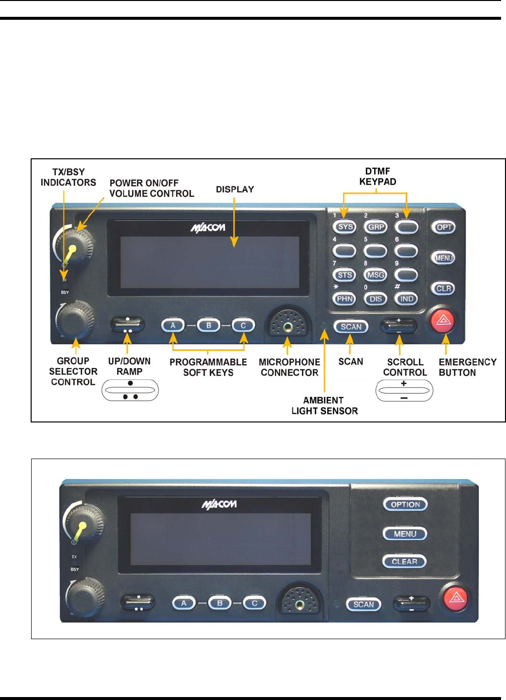
7.1 CH721 FRONT PANEL COMPONENTS
The front panel of the control head includes a dot matrix display, controls for menu navigation, an
emergency button, three pre-set buttons, a Power On-Off/Volume Control knob, and a microphone
connector. In addition, the system model control head features a DTMF keypad. Table 7-1 lists all default
front panel controls and their functions.
Figure 7-1: System Model
Figure 7-2: Scan Model
MM-014716-001
18
The buttons on the front panel are backlit for operation in a low ambient light level such as nighttime
operation. Some buttons also flash to provide feedback of various operating conditions.
In addition, the front panel contains a light-level sensor that samples ambient light levels for automatic
display and button backlight brightness adjustments. In other words, it automatically brightens the display
and backlights when higher external light levels exist and it automatically dims the display and backlights
during lower external light levels.
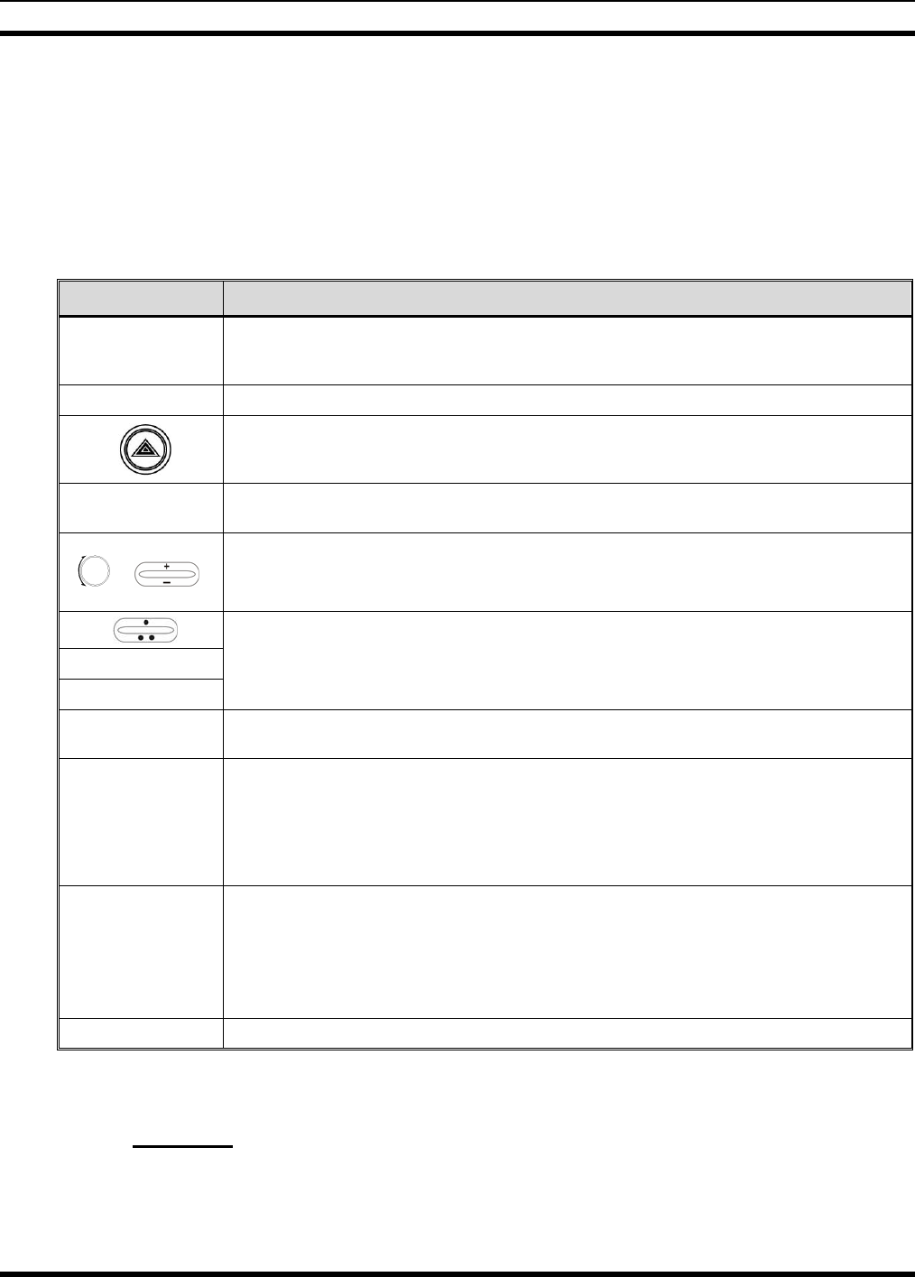
Table 7-1: Front Panel Default Controls and Functions
PART FUNCTION
Power On-
Off/Volume Control
knob
Turn knob clockwise to power on the radio and increase volume.
Turn counter-clockwise to decrease volume and power off the radio.
Mic Connection Connection for hand-held, hands-free, speaker-mic, or headset.
If enabled through programming, the emergency button sends an emergency alert and opens
voice communication on the currently selected talk group or the default emergency talk group
(depending upon how the system is defined).
Ambient Light
Sensor Radio automatically adjusts the display and button backlight brightness level based on
ambient light. Do not block this sensor.
or
While in the dwell display, scrolls through available talk groups.
Scrolls through selections within the active menu (available talk groups, pre-programmed
speed dial numbers, canned alert messages, etc.).
OPT/OPTION
CLR/CLEAR
Scrolls through available menu items.
MENU Press to activate the current selection. In some cases, this is not necessary as the last
selection will automatically activate after a short period.
Display Area
Menu selections and messages.
Network Connectivity icon.
Current Volume Level icon.
Volume represented numerically within the display (0 = Muted, 40 = Loudest).
User may select which one of several dwell displays the radio uses.
Pre-Set Buttons
A, B, & C
These buttons are used to store and recall user-selectable parameters such as scan mode,
selected profile, selected talk group, and priority talk group. Different parameters can be
stored at each of the three different pre-set buttons.
Preset button C can be configured via programming to reboot the radio into a particular
application mode. Contact your system administrator to determine if this feature is enabled in
your radio.
SCAN Not functional in OpenSky systems.
7.2 POWER UP AND VOLUME CONTROL
7.2.1 Power Up
1. Rotate the Power On-Off/Volume Control knob clockwise to power on the radio. The display will
illuminate when the radio powers up.

MM-014716-001
19
2. Wait for the power-up sequence to complete, which takes approximately ten (10) seconds.
During this time, if enabled for auto registration, the radio is provisioned with a customized user
personality designed for the user’s specific needs by the OpenSky network administrator.
If this personality contains encrypted talk groups or if the user is authorized for, and intends to use,
manual encryption, User Login must be performed. This requires a system model control head so that
the User ID and password can be entered.
3. When provisioning is complete, the radio will display the Dwell Display.
If User Login is required, the bottom line of the Dwell Display will flash the message “Pls Login.”
7.2.2 Volume Control
Turn the Power On-Off/Volume Control knob clockwise to increase the volume and counter-clockwise to
decrease the volume.
7.3 SELF-TEST
After power-up, the M7300 radio undergoes a multi-function automatic registration procedure. As many
as sixteen (16) possible radio profiles are downloaded to the radio from the network in response to the
User’s ID.
7.4 LOGIN TO THE NETWORK
Login occurs either automatically (auto registration) if the radio has a valid registration or, if enabled and
authorized for encryption (Section 7.30), requires the user to enter a User ID and password.
If encryption is enabled and authorized on the radio, the user will be prompted to “Pls Login” with the *1
login command, a User ID, and password [System Model Control Head required].
1. Press *1 (Login command).
2. Enter the full 10-digit User ID.
3. Press the # key.
4. Enter the password.
• If the radio is configured for alpha-numeric passwords and the password has consecutive
duplicate numbers (“MES33” for example), enter # between the consecutive duplicate numbers
so the radio will not interpret the entry as a letter (“D” in this example).
• If the radio is configured for numeric-only passwords, do not enter # between duplicated
numbers.
5. Press the # key twice.
The User ID may be remembered from the previous log-in. (Refer to Section 7.5 for further details
regarding log-off commands.) The password will be established before the radio is put into operation.
Contact the local OpenSky network administrator for more information.
If necessary, contact radio system administration personnel for log-in assistance and/or
radio-specific log-in instructions.
MM-014716-001
20
7.5 LOG OFF THE NETWORK
The *0## command de-registers the radio. Typically, this is automatically performed when powering
down the radio. Using this method, the User ID is remembered by the radio so only the password is
needed at next log-in. Manually log-off by pressing *0## (requires System Model).
If a user is logged in using encryption features, it is necessary to log-off when encryption is no longer
required.
7.6 TURNING THE RADIO OFF
To turn the radio off, rotate the Power On-Off/Volume Control knob counter-clockwise. In multiple
control head installations, turning off the last powered-up control head will also automatically turn off the
radio.
Several user-selected radio settings (i.e., scan mode, pre-set buttons, and side tone levels) are maintained
for the next operational session. At the next radio power-up, maintained settings will automatically
restore, along with the network personality settings. In multiple control head installations, settings are
maintained for each control head position.
If power is abruptly disconnected from the radio prior to executing the correct turn-off
procedure, user-selected radio settings and last-tuned channel information will be lost.
This can extend the time required for the radio to register with the network upon the
subsequent power-up.
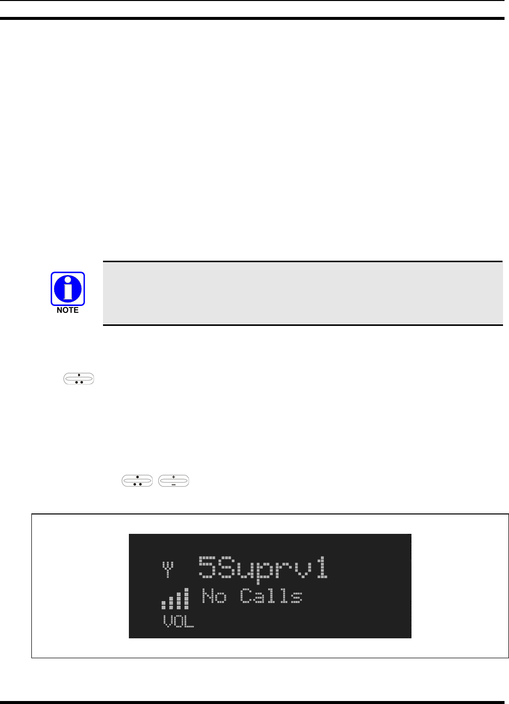
7.7 MENU DISPLAY AND CONTROL AREA
Following power-up, the radio display shows the default talk group (Figure 7-3). Pressing up or down
with changes the display to the next available menu. In many cases, the dwell display
automatically re-appears after no menu buttons are pressed for a short period of time (between 10 and 30
seconds). For some menus such as the GPS and User ID menus, this does not occur until the user presses
a front panel button.
When the dwell display is active, it will change dynamically to reflect the current profile, received talk
group/caller ID (when available), or channel (when enabled).
The radio’s display is highly interactive. It responds in the top and bottom text lines as the user presses
the menu buttons ( , and MENU) to scroll through the menu loop and the entries for each
menu. Table 7-4 outlines the basic menu structure.
Figure 7-3: Typical Display
MM-014716-001
21
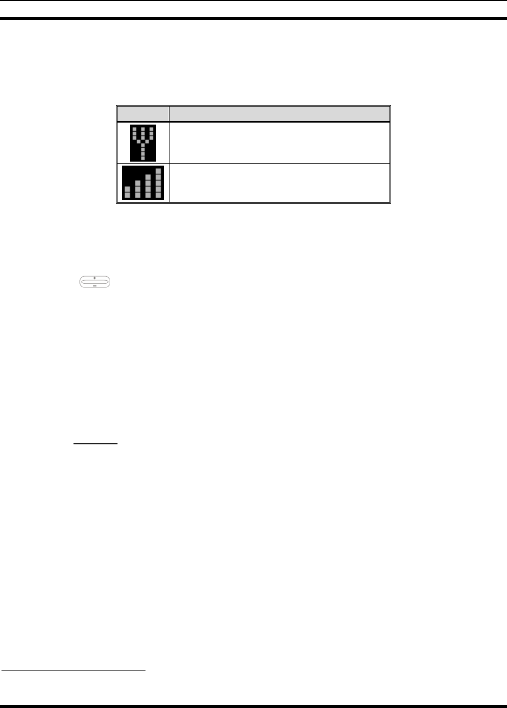
7.8 RADIO STATUS ICONS
Status Icons indicate the various operating characteristics of the radio. The icons show operating modes
and conditions (see Table 7-2). The location of icons on the display may vary depending on configuration.
Table 7-2: Icons and Descriptions
ICON DESCRIPTION
Indicates data registration.
Volume bars – indicates relative volume level.
7.9 DWELL DISPLAY
When not engaged in menu selection, the first two lines of the display default to the user-defined display,
known as the “dwell display.” The top line indicates the currently selected talk group. The second line
will display the currently selected profile, caller ID/alias1, received talk group, and current channel name.
Press the ramp control to scroll through and view one of these second line options.
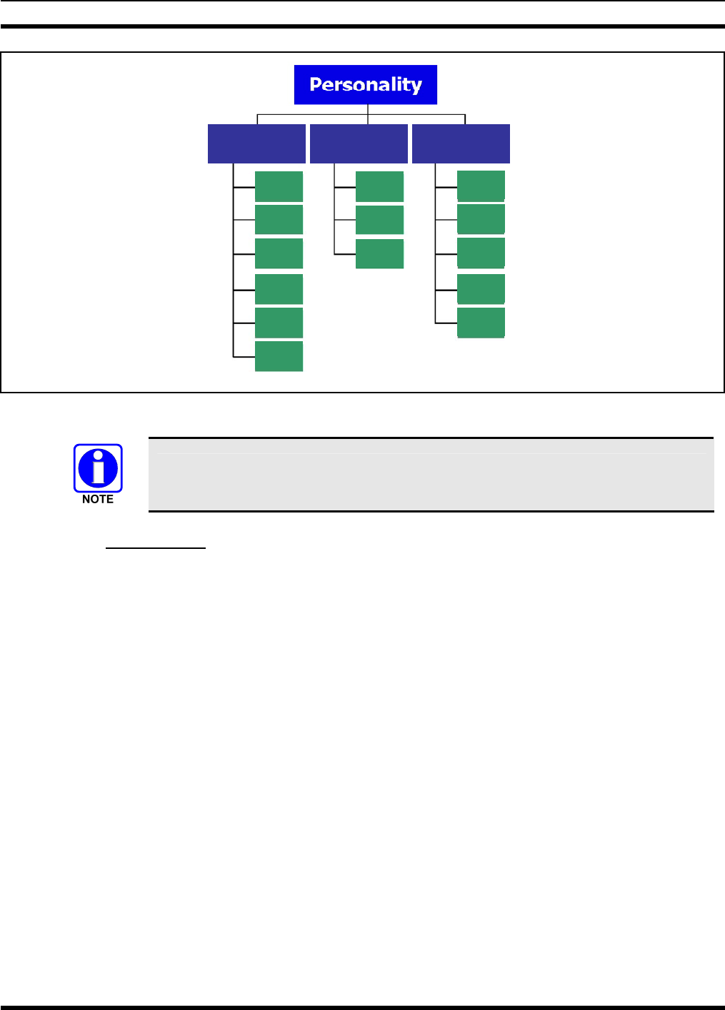
7.10 PERSONALITY
As illustrated in Figure 7-4, a personality defines the profiles and talk groups available to the user. It is
the structuring of a collection of profiles and privileges established by the OpenSky network administrator
to provide the user with a comprehensive set of profiles to communicate effectively with the necessary
talk groups or individuals.
Personalities are stored on the network and downloaded over-the-air to the radio. This process is called
“provisioning.” Provisioning occurs at radio power-up and at user log-in. Each personality can contain up
to sixteen (16) profiles and each profile can contain up to sixteen talk groups.
7.10.1 Profiles
As stated above, each profile can contain up to sixteen (16) talk groups. A profile also defines the radio’s
emergency behavior. All transmissions are made on the selected talk group (displayed on the top line of
the dwell display). The user can change the selected talk group to any of the other talk groups within the
profile.
1 Alias is a logical ID name such as “J_Smith.” The name corresponds to a user ID such as 003-542-0001.
MM-014716-001
22
TG a
TG b
TG c
TG x
TG y
TG z
TG d
TG e
TG f
TG a
TG d
TG g
TG h
TG i
TG = Talk Group
Profile 1 Profile 2 Profile 3
Figure 7-4: Personality Structure Example
If Global Profile is enabled by the system administrator, the number of available talk
groups to scan doubles.
7.10.2 Talk Groups
A talk group represents a set of users that regularly need to communicate with one another. There can be
any number of authorized users assigned to a talk group. Talk groups are established and organized by the
OpenSky network administrator. An OpenSky talk group is similar to a channel within a conventional FM
radio system.

MM-014716-001
23
7.11 ALERT TONES
The M7300 radio also provides audible Alert Tones or “beeps” to indicate the various operating
conditions (see Table 7-3).
Table 7-3: M7300 OpenSky Mode Alert Tones
NAME TONE DESCRIPTION
Call Queued one low tone/two high tones Call queued for processing.
Call Denied three short beeps Radio is out of coverage area or requested talk group is
active.
Grant (or Go-Ahead) single short beep
Sounded when resources become available for a call
request placed in the queue (if enabled) upon channel
access.
If the radio roams to another site while transmitting, then
it will auto rekey and begin transmitting on that tower. It
gives a second grant tone to let the user know they have
roamed.
Call Removed single long low-pitched tone Notifies the user access to the channel has been lost
(out of coverage area or pre-empted by higher-priority
call)
Selective Alert
Received four short tones Only played once to indicate a selective alert has been
received.
Emergency Alert Tone three long tones Sounds when an emergency alert is declared
Emergency Cleared
Tone one long low-pitched tone Sounds when an emergency is cleared
Selective Call Ring
Tone a ringing tone similar to a
telephone
Ringing is repeated every four seconds until the call is
accepted or rejected by the radio being called or until the
network drops the call if unanswered after one minute
PSTN Ring Tones a single medium-pitch
repeating tone
Two ring tone - one generated by the radio when there is
an incoming telephone call or an outgoing telephone call
attempt is waiting for the telephone interconnect gateway
equipment to dial the Public Switched Telephone
Network (PSTN). The second ring tone sounds when the
gateway equipment has dialed the number.
Roam Tone Two short tones, one high-
pitched and one low-
pitched
Sounds when the radio transitions from one radio base
station site to another.
Out of Range Tone three brief tones If enabled via programming, sounds at a programmable
interval while the radio is in a state of persistent
deactivation.
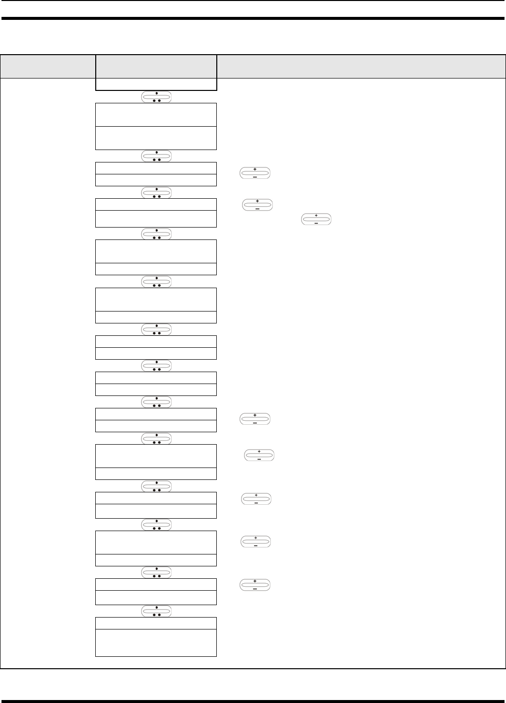
7.12 BASIC MENU STRUCTURE
Table 7-4 illustrates the basic M7300 OpenSky menu structure. Menu items will vary depending upon
system programming, radio hardware, and optional configurations. All menus except the dwell display
menu can be turned off by network administration personnel.
MM-014716-001
24
Table 7-4: Basic Menu Structure
Menu Name Radio Displays
(top and bottom lines) Usage Notes
To/From Dwell Display
registration, RF sync and
transceiver status codes
Engineering Display
(Menu may not be
available per
programming.) bit-error rates
and RSSI data
Displays radio system connection data. For engineering use.
OFF/ON
Silent Emergency “SilentEmerg” Use to toggle Silent Emergency OFF/ON.
available modes
Operating Mode
(e.g., OTP, EDACS, etc.) “Mode Menu” Use to choose an available mode. Press MENU and
confirm (Y/N) with and press MENU again.
current latitude and
longitude
GPS Fix “GPS Fix”
Radio’s current GPS latitude and longitude position scrolls
across top line of the display. Applies to GPS-equipped radios
only.
User ID # of user
currently logged in
User ID “User ID”
User’s identification/name scrolls across top line of the display
(if programmed).
Radio’s IP address
IP Address “IP Address” Radio’s Internet Protocol (IP) address scrolls across top line of
the display.
station’s call sign
Station Identification “Station ID” Station’s identification/name scrolls across top line of the display
(if programmed).
“OFF”
Stealth Mode “StealthMenu” Use to enable. Press any button to disable.
“LOW”, “MEDIUM”,
“MEDHIGH”, “HIGH”
Treble Level “Treble Menu”
Use to choose speaker/headset treble level. Press
Select to return to dwell display.
“<< >>”
Display Brightness “Bright Menu” Use to dim or brighten. Press MENU to return to dwell
display.
“OFF”, “LOW”, “MED”,
“HIGH”
Side Tone Level “Side Menu”
Use to choose side tone level. Press MENU to return to
dwell display.
“ON” or “OFF”
Intercom “INTERCOM” Use to turn intercom on and off. Press MENU to return to
dwell display.
selected channel Selected Channel
(Menu may not be
available per radio
programming) “ChannelMenu” Displays the current channel. Press MENU to return to dwell
display.
See Next Page
MM-014716-001
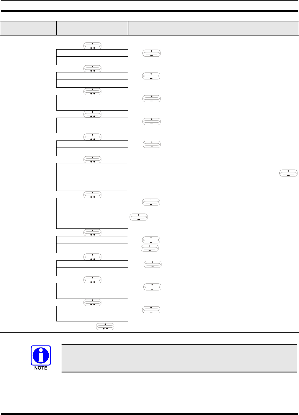
25
Menu Name Radio Displays
(top and bottom lines) Usage Notes
See Previous Page
current scan mode
Scan Mode “ScnModeMenu” Use to turn scan on and off. Press MENU to return to
dwell display.
talk group “<”
Talk group
Lock Out “LockOutMenu” Use to choose a talk group for locking/unlocking. Press
MENU to toggle “<” on (locked out) and off.
current priority talk group
Priority 1
Talk group “Priority2” Use to choose new priority talk group. Press MENU to
return to dwell display.
current priority talk group
Priority 2
Talk group “Priority1” Use to choose new priority talk group. Press MENU to
return to dwell display.
alert received
Emergency Dismiss “EmgDismiss” Use to choose emergency talk group. Press MENU to
dismiss.
time/sender’s name/
alias/message text
Alerts Received “AlertsRcvd”
or oldest message
“No alerts” or alert message text scrolls in display. Use
to view messages.
current speed dial #
Alert Destination “AlertDest”
Use to choose a speed-dial number. Press MENU to go
to “AlertMsg” menu. Scroll through canned messages with
. Press MENU to send message and return to dwell
display.
current speed dial #
Speed Dial “SpeedDial” Use to choose a speed-dial number. Press MENU, then
use to select canned message.
currently active profile
Profile Selection “ProfileMenu” Use to choose an available profile. Press MENU to
return to dwell display.
selected talk group
Talk group
Selection “TalkGrpMenu” Use to choose a talk group in current profile. Press
MENU to return to dwell display.
Selected talk group
Dwell Display (bottom line option) Use to scroll top line through talk groups. Press MENU
to change bottom line option.
Use , CLR, or OPT to scroll through menus.
Menus will vary depending upon system programming, radio hardware, and optional
configurations.
MM-014716-001
26
7.13 DUAL-TONE MULTI-FREQUENCY
Dual-Tone Multi-Frequency (DTMF) is the system used by touch-tone telephones. DTMF assigns a
specific tone frequency to each key so a microprocessor can easily identify its activation. The radio
supports DTMF with a system model control head (Figure 7-1). This allows for specific tasks such as
entering a user ID and password, or selective calling.
When a key on the DTMF keypad is pressed, the DTMF tone is played through the radio’s speaker.
7.14 KEYPAD COMMANDS (SYSTEM MODEL CONTROL HEAD)
To perform a command from the keypad, press the * key followed by one of the pre-set function keys as
follows:
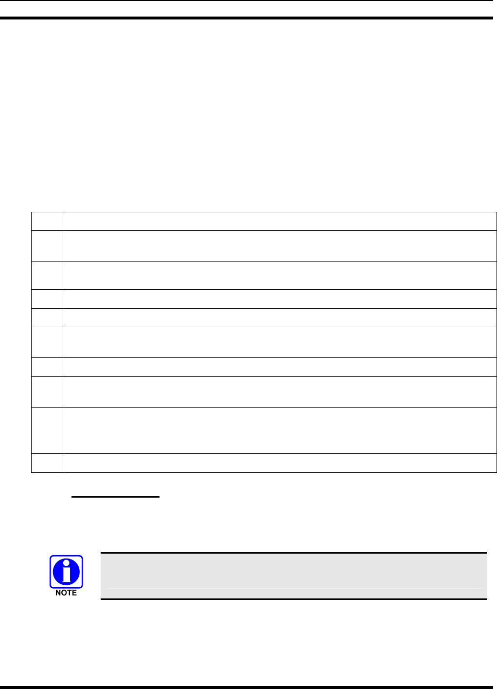
Table 7-5: Keypad Function Commands
*0 Log-off command: *0## (logs the user off the system). See page 20 for additional information.
*1 Log-in command: *1<User ID> # <Password> ## (required for encryption). See page 19 for
additional information.
*4 Enter Scene of Incident Mode (SOI) on specified channel and band:
*4#<channel>#<Band>#
*4# Exit SOI Mode.
*6 Go to default profile: Selects default profile if the radio is not voice registered.
*7 Initiate Selective Alert command: *7<Target ID>#[Choose Message]#. See page 35 for
additional information.
*8 Radio-to-Radio Call command: Selective call number # (PTT to dial).
*9 Public Switched Telephone Network (PSTN) Call command: See page 36 for additional
information.
*32 Begin Manual Encryption command: *32<Pre-Determined Encryption Key >#
1 – 16 digit encryption key for 128 bit encryption; 17 – 32 digit encryption key for 256 bit
encryption. See page 40 for additional information.
*33 End Manual Encryption command.
7.14.1 Password Entry
Password entry requires a system model control head. Password characters are encrypted on the display
using symbols to indicate the entry. The encryption symbols for each entry will appear in the display as
they are scrolled through, for example: '-' and '+'. Press the # key twice to complete the entry process.
If the password is wrong, the radio will not successfully register with the network for
wide area voice reception. The radio can still be used in single-site mode.

MM-014716-001
27
7.14.2 DTMF Overdial
Using the keypad on a System Model, the radio can transmit DTMF tones corresponding to
numbers/characters 0 — 9, * and # on the keypad. To overdial numbers/characters, transmit by pressing
and holding the PTT button and then, press the corresponding keys (one at a time) on the keypad.
7.15 CHANGING THE ACTIVE PROFILE
The radio can store up to sixteen (16) standard profiles, one of which is the currently active profile. To
change the currently active profile:
1. Scroll through the menu with until “ProfileMenu” is displayed.
2. Use to scroll through the list of available profiles.
3. Profile becomes active when selected for longer than 2 seconds, when the MENU is pressed, or when
the menu is changed using .
7.16 CHECKING OR CHANGING THE SELECTED TALK GROUP
Each profile stored in the radio can have up to sixteen (16) talk groups. One talk group within the
currently active profile is set as the “selected talk group.” For the radio user, the selected talk group is
typically the focus of most voice transmissions and receptions. There are two ways to change the selected
talk group:
First Method:
1. Use to scroll through the menu until “TalkGrpMenu” appears on the bottom line of the
display. The currently selected talk group appears in the top line of the display.
2. Use to scroll through the available list of talk groups in the active profile. This list is
determined by the OpenSky network administrator.
Second Method:
From the dwell display, use the talk group selection knob or to scroll through the available list of
talk groups in the active profile.
7.17 ADJUSTING DISPLAY AND BUTTON BACKLIGHT BRIGHTNESS
The radio uses a light sensor on the front panel to automatically adjust display brightness and button
backlight brightness to ambient light conditions. The display and backlights automatically brighten at
higher external light levels and automatically dim at lower external light levels. However, the “Bright
Menu” gives the user some manual brightness control as follows:
1. Using , scroll through the menu until “Bright Menu” appears.
2. Use to increase or decrease brightness. Display and button backlight brightness will
immediately dim or brighten.
7.18 STEALTH MODE
For some users, it is important to be able to turn off the radio’s display lights, button backlighting, volume
and side tones, but not the radio traffic. For example, in covert operations, lights and sounds could
inadvertently expose an otherwise unobservable radio user. For this purpose, the radio has a Stealth
feature that disables the radio display light, indicator light and audible side tones.
MM-014716-001
28
When stealth mode is on, the radio continues to scan the programmed list of talk groups and the user can
key-up on the selected talk group.
7.18.1 Enabling Stealth Mode
1. Using , scroll through the menu until “StealthMenu” appears.
2. To immediately turn stealth mode on, press (+) or (-) with .
3. To turn stealth mode off, press any button on the radio’s front panel.
7.18.2 Disabling Stealth Mode
Pressing any radio button other than the mic’s PTT button or the emergency button on front panel will
immediately turn stealth mode off. For example, pressing the MENU button on the front panel will turn
stealth mode off.
With stealth mode on, pressing any radio button (other than the mic’s PTT button
or the emergency button) on front panel will immediately turn stealth mode off.
7.19 ADJUSTING SIDE TONE AUDIO LEVEL
The radio sounds confirming tones called “side tones” when its buttons are pressed. Most users find this
audible confirmation helpful when navigating the menus. Side tone audio level can be adjusted or turned
completely off using the “Side Menu.”
For covert operations, it may be necessary to turn off side tones. For safety’s sake, turning off the radio
during covert operations is not recommended.
To temporarily disable the side tones that could expose the user’s presence and position, use the menu
buttons to access the “Side Menu” and select “Off” from the menu choices.
If the radio is operating properly but side tones are not heard when the menu buttons are pressed, the side
tones are probably turned off. To turn them back on, access the “Side Tone” menu and select a setting
other than “off.”
Use the following procedure set side tone level:
1. Use to cycle through the menu until the “Side Menu” appears in the bottom line of the
display.
2. Use to change to the desired level (Off, Low, Medium, and High). To turn side tones
completely off, use the “Off” setting.
7.20 CHANGE OPERATING MODE
4. Use to cycle through the menu until the “Mode Menu” appears in the bottom line of the
display.
5. Use to choose an available mode. Press MENU and confirm (Y/N) with and press
MENU again.

MM-014716-001
29
7.21 RECEIVING AND TRANSMITTING VOICE CALLS
As soon as the radio completes the startup/log-on/provision/self-test sequence and registers on the
OpenSky network, voice calls from talk groups in the active profile will be audible.
7.21.1 Receiving a Voice Call
No action is required to receive a voice call. The display responds to incoming voice calls as follows:
• When the dwell display is set to received talk group and the scan mode is Normal or Fixed:
a. If the received talk group matches the selected talk group, then the alias (if available) or user id of
the incoming caller is displayed.
b. If the received talk group does not match the selected talk group, then the received talk group
name is displayed
• When the dwell display is set to received talk group and the scan mode is None:
a. If the received talk group matches the selected talk group, then the alias (if available) or the user
id of the incoming caller is displayed.
b. If the received talk group does not match the selected talk group, then None is displayed.
• When the dwell display is not set to received talk group, then there is no display indication of an
incoming call.
Refer to Section 7.25 for detailed information on talk group scanning. Refer to Section 7.30 for detailed
information regarding sending and receiving encrypted calls.
7.21.2 Transmitting a Voice Call
Transmit a voice call as follows:
1. Turn the radio on.
2. If required, log-in to the network using a user ID and password (see Section 7.4).
3. Select the desired talk group for transmitting on.
4. Press and hold the Push-to-Talk (PTT) button on the hand-held microphone, pause for a moment,
and then speak normally. For maximum clarity, hold the microphone approximately 1 ½ inches from
the mouth and do not shout or whisper into it. If the call is queued by the network, wait for the grant
tone to sound before speaking.
5. Release the PTT button when finished speaking.
Refer to Section 7.30 for detailed information regarding sending and receiving encrypted calls.
7.22 ADJUSTING AUDIO TREBLE LEVEL
The tone of received signals can be adjusted using the radio’s “Treble Menu” as follows:
1. Use to scroll through the menu until “Treble Menu” appears. The radio’s current treble level
setting indicates in the top line of the display. There are four levels available: low, medium, medium-
high and high.
2. Use to increase or decrease.
3. Press the MENU button or wait a few seconds to return to the Dwell Display.
MM-014716-001
30
7.23 INTERCOM MODE
The optional intercom mode gives users at multiple control heads connected to the same radio the ability
to communicate with each other without transmitting over-the-air. Turn intercom mode on and off using
the “INTERCOM” menu as follows:
1. Use to cycle through the available menu items until “INTERCOM” appears in the display.
2. Use to toggle between “On” and “Off.”
When intercom mode is turned on:
• Incoming voice calls will override intercom communications for the duration of the voice call. The
radio and associated control heads will remain in intercom mode and intercom communications will
resume when the voice call ends.
• “TG: INTERCOM” appears in the control head’s display when talking on the intercom. This indicates
microphone audio is not sent out on the selected talk group; rather, it remains localized between the
radio control positions (i.e., the control heads connected to the mobile radio).
• If a call exists on the currently selected talk group when a PTT button is pressed at one of the control
heads, “TG: in use” appears in the display to indicate intercom mic audio cannot preempt the call on
the talk group.
CAUTION
A user at a radio with only one control head/front panel can turn intercom mode on. In
this case, pressing the microphone’s PTT button will not send microphone audio
anywhere.
7.24 TALK GROUP LOCK OUT
There are two ways of focusing voice communications by suppressing calls from talk groups in the
currently active profile:
1. No Scan. By turning scan off (selecting “No Scan” via the “ScnModeMenu”), only the selected talk
group is audible.
2. Lock Out. By locking out selected talk groups, the “chatter” of the locked-out talk groups cannot be
heard. This focuses the user’s scanning resources to calls only on desired talk groups.
Talk group lock out is a scan-related feature. With lock out, one or more talk groups in the active profile
can be temporarily disabled from being scanned. Calls are not received on locked-out talk groups. Lock
out settings are not retained between profile changes or when the radio is power cycled.
Lock out is a listening (receive) function and only blocks received calls on locked out
talk groups. Lock out does not affect transmit capability. The above methods do not
apply to recent emergency lock outs.
Only talk groups in the active profile can be locked out, since they are the only talk groups whose voice
calls can be heard on the radio.
P1 and P2 talk groups cannot be locked out.
MM-014716-001
31
The default emergency and emergency-capable talk groups can be locked out if they are NOT in an
emergency state. If a talk group is locked out and is subsequently changed to the currently selected talk
group, it will automatically be unlocked by the radio so the user can hear calls on the talk group. The
radio may be configured so all talk groups are automatically locked out by default. In this case, they must
be manually unlocked, if desired.
7.24.1 Lock Out a Talk Group
1. Use to scroll through the menu until “LockOutMenu” appears in the bottom line of the
display. The name of a talk group in the currently active profile will appear in the top line.
2. Use to scroll through the list of talk groups, if any, until the desired talk group for lock out
appears in the top line of the display.
3. Press the MENU button to lockout the displayed talk group. A less than symbol (<) appears next to
the talk group’s name.
4. Repeat steps 2 and 3, as needed, to lockout additional talk groups.
The dwell display will re-appear a few seconds after button presses end.
While scrolling through talk groups in the active profile, the only talk groups that appear in the
“LockOutMenu” are those in the active profile.
7.24.2 Unlock a Talk Group
1. Use to scroll through the menu until “LockOutMenu” appears in the bottom line of the
display. The name of a talk group in the currently active profile will appear in the top line.
2. Use to scroll through the list of talk groups, if any, until the talk group desired for unlocking
appears in the top line of the display. A less-than symbol (“<”) appears next to the name of a talk
group that is currently locked out.
3. Press the MENU button to unlock the talk group. The less-than symbol (“<”) next to the name of the
talk group disappears. The dwell display appears as soon as the radio acknowledges the selection.
• Changing the active profile removes any lockouts you have made.
• Turning off the radio removes any lockouts you have made.
7.25 SCANNING
Three scanning modes are available for the radio, but only one can be active at any time. Changing the
scanning mode changes the way the radio scans voice calls for all of profiles in the radio personality, no
matter which profile is or becomes active.
As described in Table 7-6, the choice of scanning mode changes the span of communications with all the
talk groups in the radio’s profiles, but does not affect interaction with the talk groups.
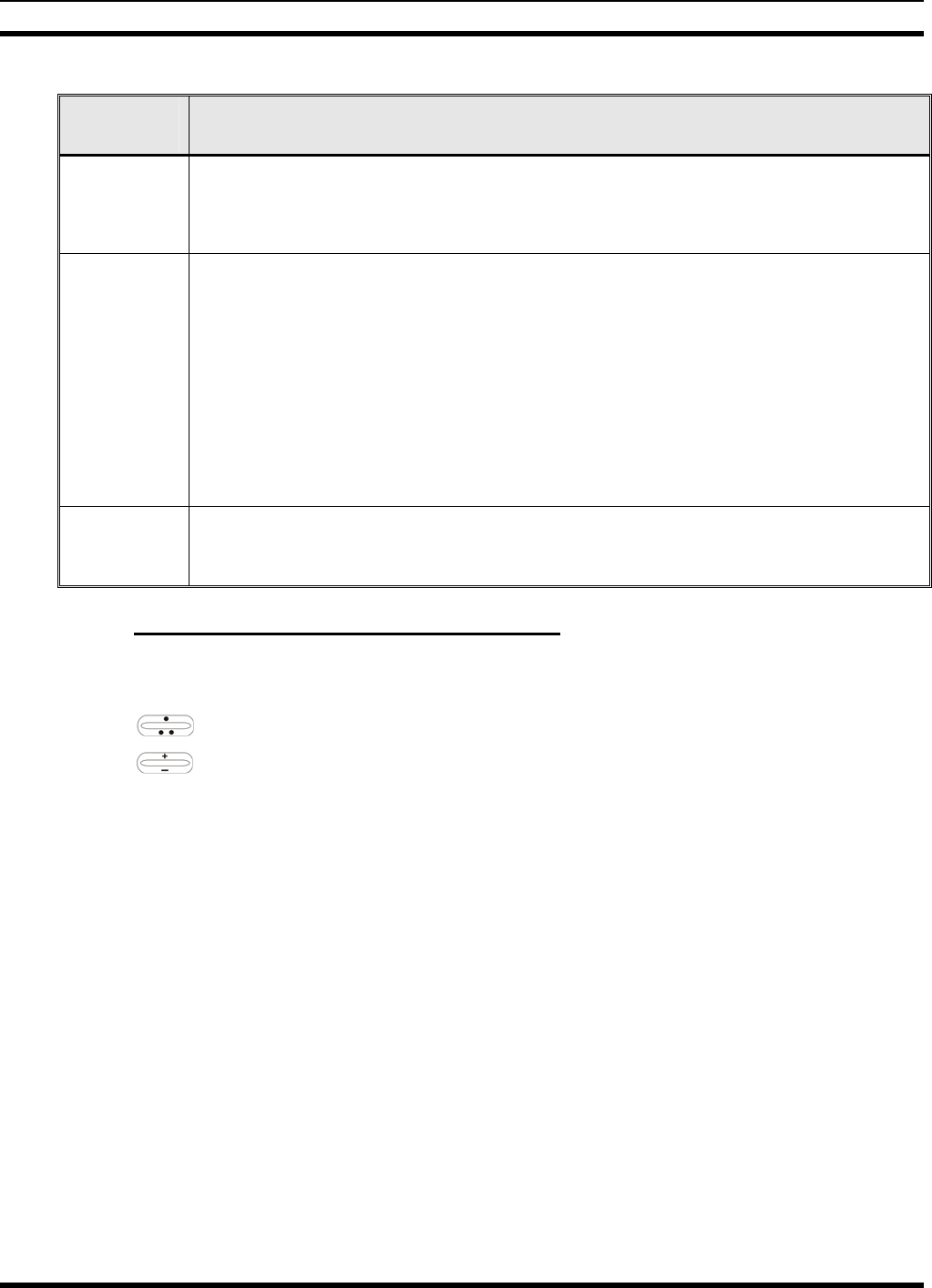
MM-014716-001
32
Table 7-6: Scan Modes
SCAN
MODE EXPLANATION
No Scan
Eliminates distractions.
Full communications (transmit and receive) on selected talk group.
No calls received from other talk groups.
Normal
(Default)
The user can scan all talk groups in the active profile that are not locked out as long as
there is demand on the site.
Priority (P1 and P2) groups are user selectable.
Receive calls from more than one talk group, if available from the current site.
Allows dragging of the selected talk group, P1, P2, and default emergency talk groups to
the site on which the radio is registered. (If other calls are available at the site, they also
can be heard but they will not be actively dragged.)
The default emergency talk group, as well as any emergency-enabled talk groups, is only
dragged if it is in emergency mode.
Fixed Functions the same as Normal Scan Mode except the priority groups are fixed to the
selected profile’s pre-defined P1 and P2 groups (configured via the UAS). In this mode,
P1 and P2 groups CANNOT be locked out.
7.25.1 Checking or Changing Active Scan Mode
The currently active scan mode does not appear in the dwell display. To check it, access “ScnModeMenu”
and observe it in the top line of the display. To change the active scan mode:
1. Use to scroll through the menus until “ScnModeMenu” appears in the display.
2. Use to scroll through the scan options until the desired mode appears. See Table 7-6.
MM-014716-001
33
7.25.2 Scanning Priority
The following lists the scanning priority order (from highest to lowest):
1. Selected talk group in emergency state.
2. Default emergency group in emergency state.
3. Selected talk group.
4. Emergency capable group in emergency state
5. Priority 1 talk group.
6. Priority 2 talk group.
7. Other (non-priority)
7.25.2.1 Changing Scanning Priority
Follow this procedure to set talk groups in the current profile as the Priority 1 or Priority 2 talk group:
1. Use to scroll through the menu until “Priority1” or “Priority2” appears in the bottom line of
the display (Priority1 group has higher priority than the Priorty2 group. The talk group currently set
as the priority talk group appears in the top line of the display.
2. Use to select a new priority talk group.
3. Press the MENU button to set the newly selected talk group as the priority talk group.
7.26 MAKING SELECTIVE CALLS
Selective calling is a feature that allows two radio units to obtain and utilize an independent voice path for
a private call. Radios can be configured to both initiate and receive selective calls or to only receive
selective calls.
In the OpenSky system, a source radio can be configured to initiate selective calls through a pre-
programmed list in memory. This method uses the “speed dial list” set up by the OpenSky network
administrator and provisioned as part of the registration process.
In addition, a properly equipped source radio can initiate a selective call to any radio in the system by
entering the ten-digit voice user ID (which looks like a telephone number) of the target device. Entering a
selective call number without using the speed dial feature requires a system model control head (Figure
7-1). See Section 7.13 for more detail.
Selective calls are terminated if an emergency is declared. The network limits selective
calls to ten (10) minutes maximum.
MM-014716-001
34
7.26.1 Manually Dialing a Selective Call (System Model Control Head)
1. Press *8 on the keypad.
2. Enter the number of the radio to be called (e.g., 027-001-0006). If the region number (first 3 digits;
027 in this example) is the same as this radio’s region number, these digits do not need to be entered.
Likewise, if the region and agency numbers (first 6 digits; 027-001 in this example) are the same as
this radio’s numbers, these digits do not need to be entered. Leading zeros can also be ignored.
3. Press and release the # key.
4. Wait approximately two (2) seconds.
5. Press and release the PTT button to initiate the selective call request. When the called party accepts
the call, press the PTT again and begin speaking.
7.26.2 Speed Dialing a Selective Call
Speed dial numbers are defined and provisioned by the OpenSky network administrator
and cannot be manually entered into the radio by the user. Contact the administrator if
changes to the speed dial list are required.
1. Scroll through the Menu options using until “SpeedDial” appears in the bottom line of the
display.
2. Using , scroll through the pre-programmed speed-dial numbers until the desired number
appears in the display.
3. Press and release the PTT button to ring the other user.
a. The ring tone is sounded.
b. If the other user accepts the call, the called user’s alias will appear in the initiating caller’s
display. The two are now in a private call until one ends the call, the call is terminated due to an
initiated emergency, or the maximum time limit of ten (10) minutes is reached.
4. To end the call, press the # button or (-) using .
7.26.3 Receiving a Selective Call
When someone calls in from another radio using the selective call function, a ring sounds in the speaker
and/or headset. Press up or down using or any number key to accept an incoming Selective Call.
Press the microphone’s PTT button when speaking (transmitting) to the caller.
Press the # button or (-) using to reject an incoming Selective Call.
A selective call will be interrupted if an emergency is declared on a monitored talk group.
7.26.4 Terminating a Selective Call
Press the # button or (-) using to terminate an incoming Selective Call.

MM-014716-001
35
7.27 SELECTIVE ALERT
Selective alert messaging is an OTP feature allowing one of up to eight (8) pre-programmed text
messages (refer to Section 7.27.3) to be sent from one radio to another. The user specifies a destination
radio’s User ID, selects one of the pre-programmed text messages, and then transmits it to the destination
radio. The message delivery system adds time-of-day information and forwards the message to the
destination (receiving) radio. The sending radio receives a brief message noting the status of the
transmission. Refer to Table 7-7 for a list of possible status messages.
The first few characters of a message are part of the message text entered when the message is
programmed. This programming is performed by the system or network administration personnel.
Messages successfully received by the destination radio are stored until deleted or until it is power cycled.
7.27.1 Sending Selective Alert Messages
The destination radio’s User ID can be selected via the menu or via the keypad on the system model
control head.
Menu Button Method:
1. Using , scroll through the menu until “AlertDest” (Alert Destination) appears in the bottom
line of the display. The current speed dial number scrolls on the top line.
2. Use to change to a different speed-dial number.
3. When the desired speed-dial number appears, press the MENU button to activate the selection.
4. Choose and send the message.
Keypad Method (System Model Control Head):
To select the destination radio’s User ID using the keypad, perform the following:
1. Press *7 on the keypad. “AlertDest” appears in the display.
2. Enter the number of the destination radio (e.g., 027-001-0006) using the DTMF keypad. If the region
number (first 3 digits; 027 in this example) is the same as this radio’s region number, these digits do
not need to be entered. Likewise, if the region and agency numbers (first 6 digits; 027-001 in this
example) are the same as this radio’s numbers, these digits do not need to be entered. Leading zeros
can also be ignored. Refer to Section 7.13.
3. Press the # key to enter the number.
Choosing and Sending the Message
After specifying the destination radio’s User ID (Section 7.27.1), the radio automatically allows you to
choose a message. The current message scrolls across the top line of the display. To choose a message:
1. Scroll through the message list using . The next available message in the list is displayed.
Pause between each arrow button press to observe the entire message as it scrolls across the top line
of the display.
2. To select and send the displayed message, press the Select button, or press the # button on the
keypad.
3. The status of the sent message will be momentarily displayed (Table 7-7).

MM-014716-001
36
Table 7-7: Status of Selective Alert
STATUS MESSAGE DEFINITION
Delivering Select Alert message transmit attempt
Busy Too busy – Try again
Dest Down Receiving radio not logged on – Not registered
Not Reg Transmitting radio not logged on – Not registered
Delivered Transmission complete
Unreachable No response
Partial Transmission interrupted
7.27.2 Receiving Messages
When a selective alert message is received by a radio, a four-beep tone (one low, two high, and one low)
is heard and “NewAlert” flashes until the new message is read. Up to eight (8) received messages are
stored. If another message is received, the first (oldest) message is automatically deleted to make room for
new incoming messages.
Displaying Received Messages
1. Using , scroll through the menu until “AlertsRecvd” (Alerts Received) appears in the bottom
line of the display. “No alerts” or the last received (newest) message appears in the display. It is
preceded by the time the message was received, and the sender’s name/alias.
2. View other received messages using .
3. To delete the message currently being viewed, press the MENU button.
Deleting Received Messages
To delete a received message:
1. Display the message.
2. Delete the message by pressing the MENU button.
3. Confirm the deletion by pressing the MENU button again.
7.27.3 Defining Pre-Programmed Messages
All selective alert messages are pre-defined by the radio system’s maintenance personnel. These messages
are sometimes referred to as “canned” messages. Custom selective alert messages cannot be created by
the radio user. The entire selective alert message, including the abbreviation, can include up to 99 text
characters.
7.28 TELEPHONE INTERCONNECT CALLS (SYSTEM MODEL CONTROL
HEAD)
7.28.1 Placing an Interconnect Call
If the radio system is equipped with Public Switched Telephone Network (PSTN) interconnect
equipment, telephone calls can be made from the M7300 using this procedure:

MM-014716-001
37
1. Press the *9 keys.
2. Enter the telephone number. Ignore dashes/spaces, and precede the number with any required access
digits such as a 1 for long distance.
3. Press the # key.
4. Wait a few seconds and then press and release the mic’s PTT button to initiate the call. An initial ring
tone plays indicating call initiation. Once the gateway picks up the call, another ring tone sounds.
5. When the caller answers, press the PTT button when speaking and release it to listen to the caller.
6. To hang-up, press the # button or (-) using .
7.28.2 Receiving an Interconnect Call
When receiving an Interconnect Call, a ring sounds in the speaker and/or headset. Press up or down using
or any number key to accept an incoming Interconnect Call. Press the microphone’s PTT button
when speaking (transmitting) to the caller.
Press the # button or (-) using to reject an incoming Interconnect Call.
7.29 EMERGENCY COMMUNICATIONS
The M7300 mobile radio can transmit both emergency voice calls and emergency alerts over the entire
network. OpenSky handles emergency calls and alerts with the highest priority.
For critical voice communications, an emergency call can be raised on the default talk group or the
currently selected talk group by “declaring” an emergency on the talk group. The exact talk group is
determined by the currently active profile. After successfully declaring an emergency on a talk group, the
declaring radio’s microphone remains “hot” for a predetermined amount of time. In other words, the radio
transmits audio for a period of time even when the microphone’s PTT button is not pressed. An
emergency talk group is provided greater priority and infinite hang-time by the radio system’s
infrastructure. Hang-time is the maximum duration of quiet time between transmissions on the talk group
before the infrastructure assets are automatically taken away. Because an emergency call is handled on a
talk group, it is received by all radios and consoles monitoring the talk group.
An emergency alert is a data message sent by the radio to the MIS console (or any console capable of
receiving it). It identifies the radio declaring the emergency, and the radio’s location (if the radio is
equipped with a GPS receiver). Voice audio is not automatically transmitted during the emergency if the
administrator configures the radio for alert notification only.
7.29.1 Declaring an Emergency Call or Alert
To declare an emergency call or emergency alert, press and release the orange Emergency button. This
button is located just to the right of the 5-button Menu and Select keypad; see Figure 7-1 on page 17. The
emergency is raised after the Emergency Raise Delay (default is one second).
• The OpenSky network administrator determines if the Emergency button is used to declare an
emergency call or if it is used to declare an emergency alert. This is based upon the radio’s currently
active profile.
• The OpenSky network administrator also determines if the emergency is declared on the currently
selected talk group or a “default” emergency talk group. Again, this is based upon the radio’s
currently active profile. A talk group upon which an emergency is declared on is considered an
“emergency talk group.”

MM-014716-001
38
• Upon successful emergency declaration:
¾ An emergency tone will sound in the radio’s speaker/headset if the radio is not in stealth mode.
¾ At the declaring radio, the Emergency button flashes red if the radio is not in stealth mode. The
administrator can configure the radio to automatically transmit upon successful emergency
declaration, at which point the MENU button will flash red. However, the MENU button flashing
red is not a requirement for successful emergency declaration.
¾ On the declaring radio during an emergency call declaration, the talk group that the emergency is
declared on is temporarily displayed and then the word “EMERGENCY” flashes on the second
line of the display.
¾ For an emergency alert declaration, “EMERG ALERT” appears in the bottom line of the display.
¾ For an emergency call declaration, other radio users and/or dispatchers at consoles will hear the
emergency signal, a distinctive 3-tone burst. They will also hear audio from the declaring radio’s
“hot” microphone, if any.
¾ For an emergency alert declaration, only dispatchers at consoles will hear the emergency signal
and, if any, audio from the declaring radio’s “hot” microphone.
¾ For an emergency call, the declaring radio’s microphone remains “hot” for a predetermined
amount of time. In other words, the radio transmits audio for a period of time even when the
microphone’s PTT button is not pressed. Audio is transmitted over the emergency talk group.
When the microphone is “hot” for this initial period (typically ten seconds), simply speak into it
for voice transmission.
If an emergency declaration is not successful, the radio will periodically re-attempt until it is successful.
During this retry period, the radio will flash “EMERG PEND” on the bottom line of the display. It will
display “EMERG RETRY” for each attempt.
7.29.2 Silent Emergency
When this feature is enabled and an emergency call or alert is declared by pressing the emergency button,
the radio will not play a tone and will display an abbreviated emergency message (default is EBA). This
feature is enabled or disabled via programming or via the menu.
If the Silent Emergency feature is enabled or disabled via programming, the setting will
survive power cycle. Enable/Disable selection via the menu will NOT survive power cycle
and the enable/disable state will revert to the programmed setting at power up.
7.29.3 Clearing an Emergency Call or Alert
Check with the system administrator to ensure that the radio is programmed to allow an
emergency to be cleared.
If enabled via programming, clear an emergency by:
1. Pressing and holding the CLR/CLEAR button and simultaneously pressing the emergency button.
2. After the Emergency Cleared Tone sounds, release both buttons.
MM-014716-001
39
If the radio is in stealth mode, clearing the emergency will take the radio out of stealth
mode.
7.29.4 Receiving an Emergency Call
Upon receiving an emergency call declared by another radio:
• An emergency tone sounds in the radio’s speaker/headset (three short high-pitched beeps).
• “EMERGENCY” flashes in the display if the radio is not in stealth mode.
• On receiving radios with the emergency talk group selected, the alias of the sending party is displayed
for 5 seconds during the open-mic period, then the word “Emergency” flashes on the second line of
the display and continues until the emergency state ends.
• If scan mode is set to “No Scan” and the emergency was declared on the selected talk group, audio on
the emergency talk group is heard in the speaker/headset. See page 31 for additional information on
“No Scan” operation.
• If scan mode is set to “No Scan” and the emergency was declared on a talk group other than the
selected talk group, the emergency talk group (identified by an “*”) must be selected before audio on
it is heard in the speaker/headset.
• If scan mode is set to “Normal” and the emergency was declared on the selected talk group, the
selected/emergency talk group’s name remains in the top line of the display. Audio on the emergency
talk group is heard in the speaker/headset.
• If scan mode is set to “Normal” and the emergency was declared on a talk group other than the
selected talk group, the emergency talk group’s name appears in the bottom line of the display. Audio
on the emergency talk group is heard in the speaker/headset.
• The declaring radio's alias appears in the bottom line of the display when the emergency talk group is
selected.
• An emergency call can be dismissed as described in the following section.
A radio declaring an emergency on a talk group has a “hot” mic time period of typically
ten (10) seconds just after it declares the emergency. This time period may be adjusted
by system or network administration personnel on a per radio basis.
7.29.5 Dismissing an Emergency Call
An emergency is dismissed for a configurable amount of time only (default = 5 minutes).
To ignore an emergency call declared by another radio user:
1. Press until “EmgDismiss” appears in the display.
2. Press until the talk group in the emergency state appears, as indicated by an asterisk (*)
following the talk group’s name.
3. Press the MENU button.

MM-014716-001
40
The emergency dismiss timer is cleared when the emergency is cleared.
7.30 ENCRYPTION
In the OpenSky network, both data and voice use a 128-bit or 256-bit key encryption standard published
by the Federal Information Processing Service (FIPS), called Advanced Encryption Standard (AES). AES
is approved by the U.S. Department of Commerce for encryption of classified materials.
When encryption is enabled on the network, data is encrypted from the MDIS to the Mobile End System
(MES) (e.g., M7300 mobile radio). This form of encryption provides air-link security.
Voice encryption is handled either automatically or manually. Automatic encryption is initiated through
the Unified Administration Server (UAS) for a specific talk group and requires nothing from the user.
Manual encryption is initiated by two or more radio users and requires system model control heads. Both
methods of encryption are discussed in the following sections.
7.30.1 Automatic Encryption
For automatic encryption, a network administrator will select the talk group to be encrypted at the
interface to the UAS. Once the talk groups have been selected and identified as secure, credentials for key
generation are generated automatically by the system and provisioned to authorized users. This process
requires that authorized users login to the network and be authenticated. Encryption keys require no
manual handling and are never sent “in the clear” over any network interface or air-link.
1. “Pls Login” appears displayed in the bottom line of the dwell display.
2. Login normally using the keypad on a system model control head to enter User ID and Password.
If a user is engaged in a call on a talk group encrypted at the network administrator level, “Secure Call”
will appear in the bottom line of the dwell display if the user is logged in to that talk group.
If a secure call is in progress elsewhere and the user has not logged in, the bottom of the dwell display
will alternate between “No Access” and the alias of the radio that is currently engaged in the secure call.
7.30.2 Manual Encryption (System Model)
Two or more users can manually encrypt a call, if enabled, without an established encrypted talk group. A
pre-determined key is required at each radio.
The key must be pre-determined by the users prior to making a manually encrypted call
on a talk group and is entered into the radio using the keypad. For 128 bit encryption, this
key is between 1 and 16 digits. For 256 bit encryption, this key is between 17 and 32
digits.
If two communicating radios have different (manually-defined) keys, receive audio at
each radio will sound garbled.
With manual encryption enabled, unencrypted radio users on the talk group can still make standard voice
(unencrypted) calls on the talk group. However, if an unencrypted user attempts to transmit on the talk
group when one of the encrypted users is already transmitting on the talk group, the unencrypted radio
will sound a deny tone and “No Access” will appear in the display. Also, the encrypted user can hear
standard unencrypted calls, but cannot respond while still manually encrypted.
MM-014716-001
41
CAUTION
Do not set a talk group for manual encryption if it has been set for encryption by the
network administration personnel.
Perform the following to transmit or receive manually encrypted calls:
1. Press *32 on the keypad.
2. Enter the key (1 – 16 digits for 128 bit encryption; 17 – 32 digits for 256 bit encryption).
3. Press the # key.
4. To end manual encryption, press *33#.
If a user is engaged in a call on a talk group that has been manually encrypted at the radio level, the user
will see “Secure Call” on the bottom of the dwell display.
If a secure (encrypted) call is in progress, and the user has not entered the key, the bottom of the dwell
display will alternate between “No Access” and the alias of the radio that is currently engaged in the
secure call.
Once the user has terminated manual encryption, “UnSecure” appears temporarily in the bottom line of
the dwell display.
7.31 PRESET BUTTONS
The front panel contains three buttons labeled A, B, and C. By holding one of these buttons down for
approximately three (3) seconds, the following current information is saved to the function of that button:
• Selected talk group
• Selected profile
• Selected priority talk group
• Lockouts
• Scan mode
• Intercom mode
Presets are saved and restored to/from non-volatile memory. Changing the User ID (login in as a different
user) will clear the presets since they are stored on a per-user basis. Changing control heads will not recall
presets for the previous control head.
Preset button C can be configured via programming to reboot the radio into a particular
application mode. Contact your system administrator to determine if this feature is
enabled in your radio.
7.32 DYNAMIC REGROUPING
Dynamic regrouping requires that the network administrator determine which radio users should be
formed into an impromptu talk group to respond to particular emergency conditions.
The administrator will edit the personalities of the affected radios to include an emergency profile and
then page the affected radios to re-register with the network to receive their edited personalities.
MM-014716-001
42
In response, affected radios automatically re-register to receive their edited personalities. During re-
registration, subscriber equipment will default to the emergency profile selected by the administrator.
7.33 GPS COORDINATES
The radio’s current latitude and longitude coordinates may be displayed using the “GPS” menu. The
following procedure assumes a GPS antenna is connected to the radio and it is receiving adequate signals
from GPS satellites:
1. Press until the “GPS” menu appears in the bottom line of the display. Current GPS coordinate
latitude and longitude data continuously scrolls in the top line of the display in a
degrees:minutes:seconds format.
2. Use to change to another menu.
If the internal GPS receiver’s data is expired (30 minutes or more) or unavailable, the
radio uses the serving base station’s coordinates [GPS (Site) is displayed]. The GPS Menu
will also indicate if the data is aged (2 minutes or more) [GPS (Aged) is displayed]
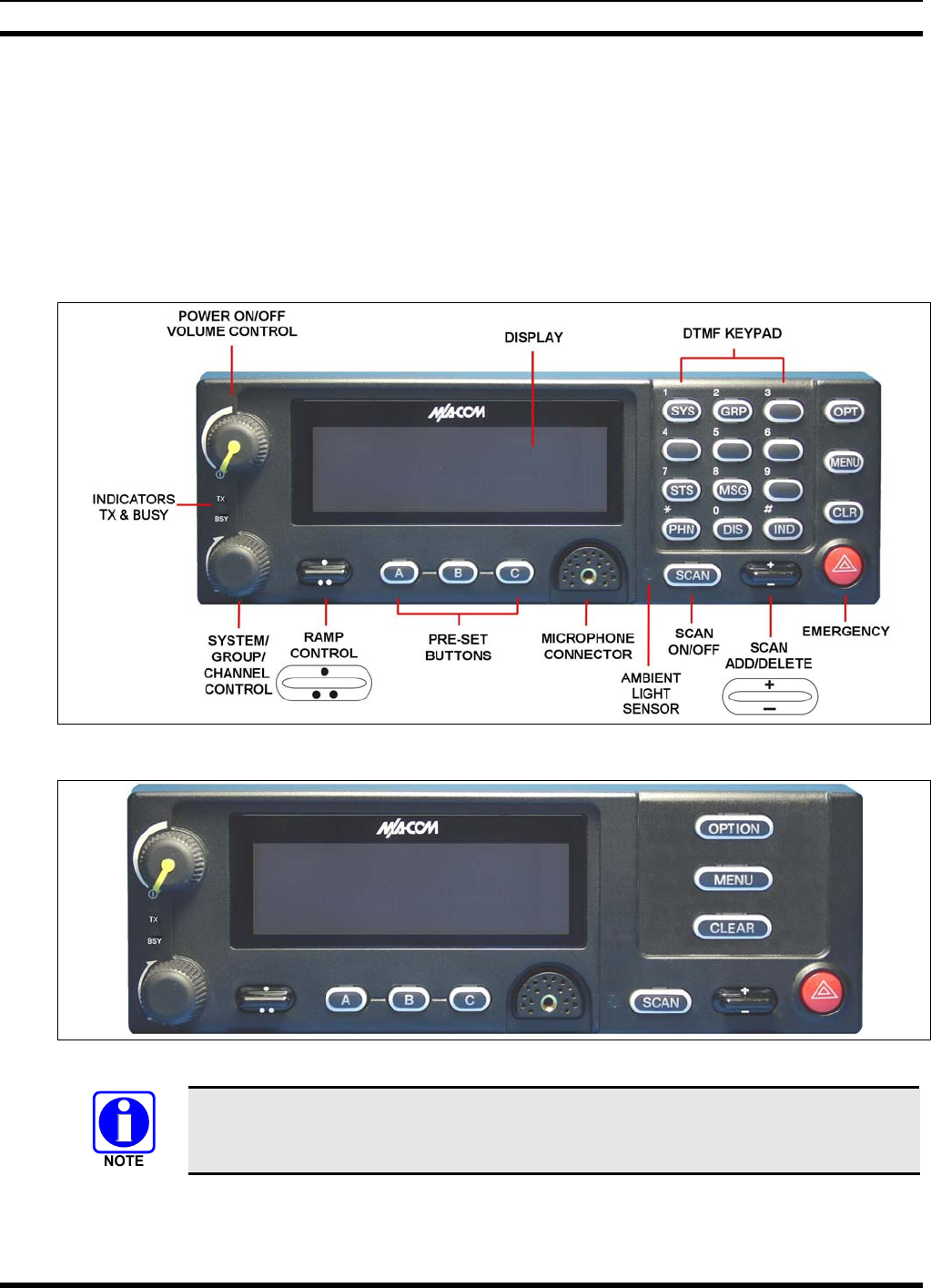
MM-014716-001
43
8 P25/EDACS/CONVENTIONAL COMMON OPERATION
8.1 CH721 FRONT PANEL COMPONENTS
The front panel of the control head includes a dot matrix display, controls for menu navigation, an
emergency button, three pre-set buttons, a Power On-Off/Volume Control knob, and a microphone
connector. In addition, the system model control head features a DTMF keypad.
Table 8-1 lists all default front panel controls and their functions. All functions and controls of the Scan
radio operate the same as the corresponding functions and controls on the System radio.
Figure 8-1: System Model
Figure 8-2: Scan Model
Button function may vary depending upon system programming, radio hardware, and
optional configurations. Complete the table in Section 14 if the keys have been
remapped to provide new functions.
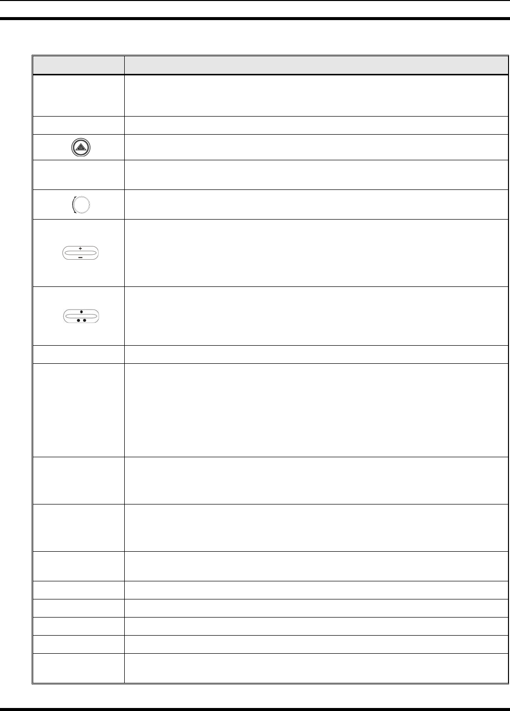
MM-014716-001
44
Table 8-1: Front Panel Default Controls and Functions
PART FUNCTION
Power On-
Off/Volume
Control knob
Turn knob clockwise to power on the radio and increase volume.
Turn counter-clockwise to decrease volume and power off the radio.
Mic Connection Connection for hand-held, hands-free, speaker-mic, or headset.
The Emergency button declares an emergency if enabled through programming.
Ambient Light
Sensor Radio automatically adjusts the display and button backlight brightness level based
on ambient light. Do not block this sensor.
This rotary switch selects the systems or groups/channels, depending upon
programming.
This rocker type button is used to display the current SCAN status for a
group/channel and then add or delete the group/channel from the system scan list.
Pressing the add/delete button twice while the radio is actively receiving or three
times when the radio is not receiving selects the last scanned channel (Last
Scanned Channel Recall).
The primary function of this rocker type button is to scroll through the System list or
the Group/Channel list depending upon programming.
The secondary function is to increment or decrement items within a list (phone list
for example).
OPT/OPTION Toggle a PC programmable feature ON and OFF.
CLR/CLEAR
In Trunked mode, the CLR button exits the current operation and removes all
displays associated with it. The radio and display then return to the group receive
state.
In Conventional mode, pressing this button unmutes the receiver so activity on the
selected channel can be monitored. When pressed and held for approximately 3
seconds, this button toggles conventional channel decoding (Channel Guard,
Digital Channel Guard, T99) ON and OFF if programmed for the selected channel.
MENU
Primary function - access the menu list. This is a list of additional features that are
not available directly from the keypad.
Secondary function - activate a selected item within a list, similar to an enter key.
SCAN
Primary function - toggle scan operation on and OFF.
Secondary function - toggle the keypad buttons between their primary function and
their secondary function.
Pre-Set buttons
(A, B, & C) Used to store and recall user-selectable parameters.
SYS Used to enter the System select mode.
GRP Used to enter the Group select mode.
STS Permits the transmission of a pre-programmed status message to an EDACS site.
MSG Permits the transmission of a pre-programmed message to an EDACS site.
PHN Used to place telephone calls through the radio by selecting the interconnect
special call function.
MM-014716-001
45
PART FUNCTION
DIS Used to adjust the current display intensity and the keypad backlight level.
IND Used to call an individual or make an all-call by selecting the individual call function.
8.1.1 Primary Functions (Quick Access)
The secondary function of the SCAN button is to toggle the keypad buttons between their primary
function and their secondary function. When the secondary keypad is active, i.e. entering phone digits for
an interconnect call, the SCAN button can be used to toggle the keypad buttons back to their primary
function, perform a task, and then toggle back to finish entering the digits for the phone number.
PRIMARY is displayed when the SCAN button is used to toggle the keypad keys back to their primary
functions. This provides quick access to the primary functions of the keypad. This is a programmable
feature of the SCAN button only. Careful consideration should be given to possible operational conflicts
before enabling this feature.
Several keys on the Scan version have a secondary function. The MENU key is the SELECT secondary
function with the CLEAR key remaining the same for the secondary function. On the System version, the
OPT has a secondary function of DELETE, MENU is SELECT, and CLR retains its CLEAR
functionality.
8.2 TURNING THE RADIO ON
Rotate the POWER ON-OFF/VOLUME knob clockwise, out of detent to turn the radio on. A short
beep (if enabled through programming) indicates the radio is ready for operation. The display indicates, if
programmed, the last selected system name on line 1 and the last selected group or channel name on line
2.
8.3 SELECTION MODE RULES
Many operations require selection from a list such as system, group or phone number. This selection
process is handled in the same manner for all lists. The ramp control, MENU, 0-9, *, #, and the
CLR button are used during the selection process. The following example systems list is used to explain
the process:
The hookswitch functions the same as the CLR key in I-Call, phone call, and menu
modes.
SYSTEM
1 NORTH
2 SOUTH
3 EAST
4 WEST
After entering a selection mode, the following generic display format will appear:
X X X X X X X X
Y Y Y = Z Z Z
MM-014716-001
46
Line 1 shows the currently selected item name (XXXXXXXX) from the list. Line 2 indicates the list
(YYY) that the selection is to be made from and the number of the selected item (ZZZ) within the list. (In
some cases the information on lines 1 and 2 will be exchanged.) Enter the system selection mode by
pressing the SYS key. If SYSTEM 2 is the current selection, the display appears as follows:
S O U T H
S Y S = 2
Line 1 contains the current system name, SOUTH; and line 2, SYS = 2, indicates that selection is from
the system list and it is the second system within the list.
A new system from the list is selected by using the ramp control or by directly entering the system
number with the numeric keys. The ramp control scrolls through the list in increasing and
decreasing order. In the previous example, pressing up with the ramp control selects the EAST
system as shown in the next display.
E A S T
S Y S = 3
The radio can be programmed to wrap around from one end of a list to the other end or to stop at the ends.
8.4 DIRECT ACCESS
To directly access a selection, enter the corresponding number (e.g. 4) followed by MENU to activate the
selection. The entered number is displayed on line 2 as shown below. Line 1 shows the current list being
used for selection.
S E L S Y S
4
If a mistake is made while entering the number, press the DEL button to backspace once and correct the
entry. If an invalid number is entered, a short low-pitched tone sounds when MENU is pressed.
To exit the selection mode, press the CLR button or wait for the time-out. If the selection mode is cleared
while an entry is pending (i.e., numbers are entered on line 2, but MENU has not been pressed), the entry
on line 2 will be disregarded and the previous selection will remain active. If the time-out activates while
an entry is pending, the entry on line 2 will be selected if it is within the valid range; if it is out of range,
the entry on line 2 will be disregarded and the previous selection will remain active.
While in system, group or channel selection mode, the radio continues to receive calls
normally and continues scanning, if it is enabled. If a call is received during the
selection mode process the radio will return to the normal receive mode display.
Continuing with the selection process will return the display to the same point in the
selection process if the selection mode time out has not yet expired. Any press of the
PTT button during the selection mode process will initiate transmission and exit the
selection mode.
8.5 FEATURE ENCRYPTION DISPLAY
Feature Encryption Display is available through the menu function and, if programmed, appears in the
menu as “FEATURES.” This data indicates current features programmed into the radio as well as
information required to add features to the radio.
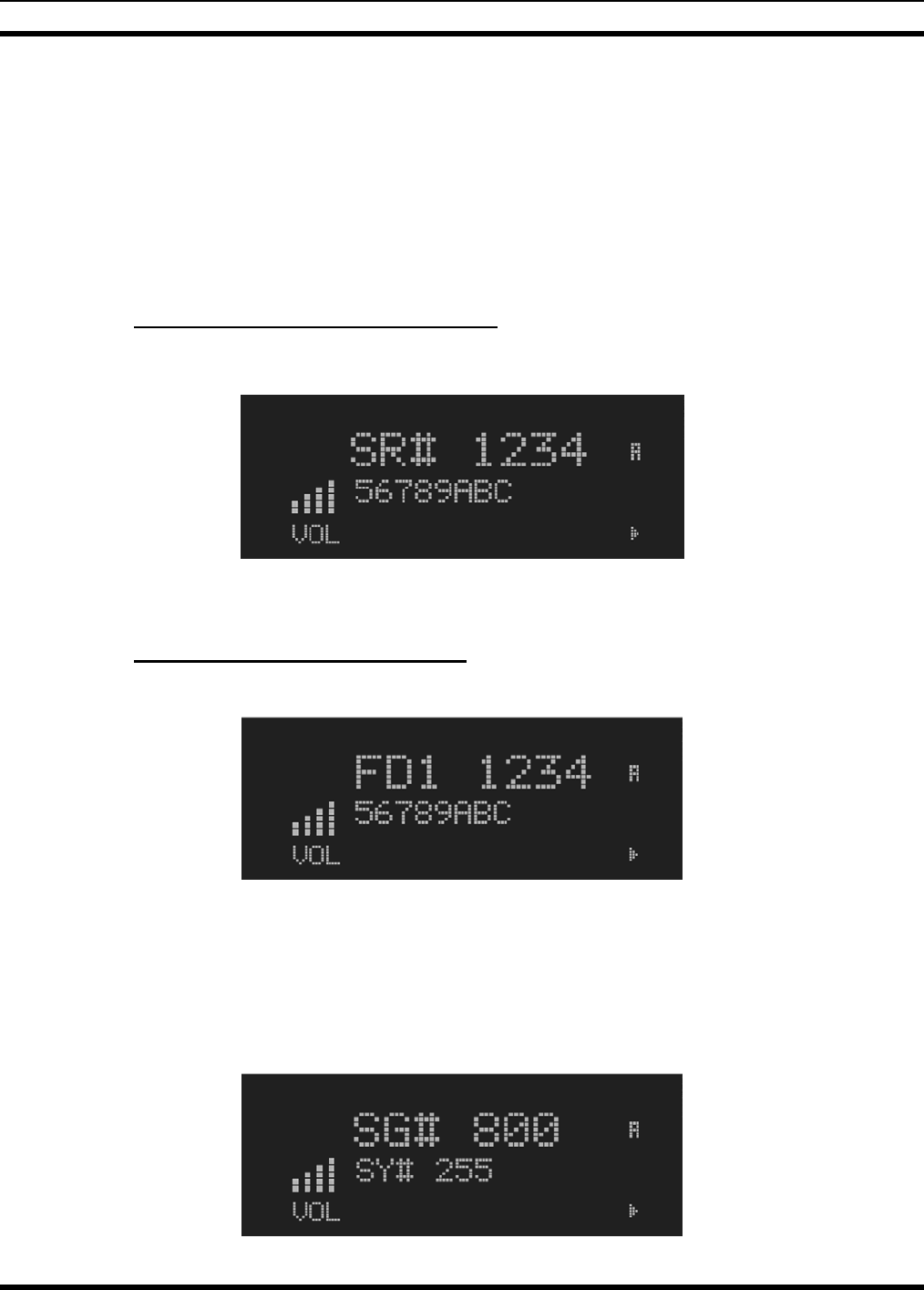
MM-014716-001
47
Once the feature has been accessed, all normal menu functions work. The user can scroll up or down
through all of the entries.
Feature Encryption Display provides the ability to view, in the order displayed, the following:
• Serial number ROM data - serial number of the ROM
• Feature encryption data stream - used to enable features
• Number Fields - defines limits
• Features enabled - displays bit fields of enabled features
8.5.1 Serial Number ROM (12 Hex Digits)
Example:
When the user wants to enable a feature in his radio, he will need to call M/A-COM, Inc. They will ask
for the ROM serial number. The serial number shown here is for example only.
8.5.2 Feature Encryption Data Stream
Example:
These data streams define the features the user has enabled in his radio and are required by M/A-COM,
Inc. to enable other features. The data streams shown here are for example only. Note: There are three
displays: FD1, FD2, and FD3. All three are required.
Number Fields
Example:
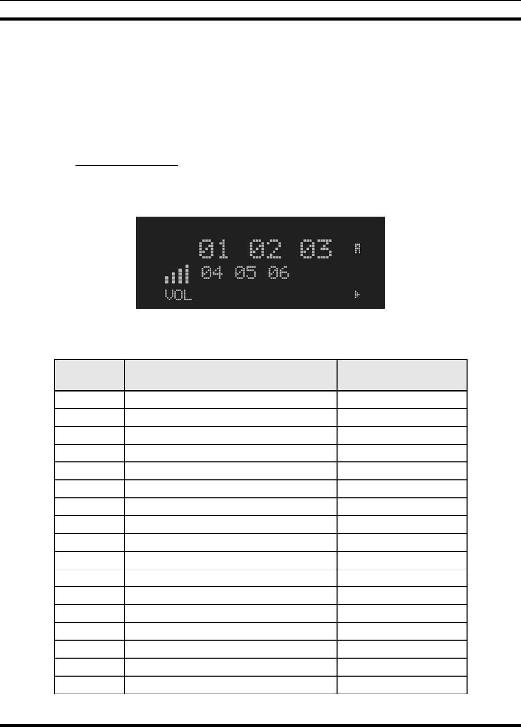
MM-014716-001
48
These number fields show the set limits of the of the user's radio as:
• SG# XXX - Maximum number of system/groups combination available
• SY# XXX - Maximum trunked system limit
• CH# XXX - Maximum number of conventional channels available
The user needs to know the limits of his radio before attempting to enable other features. The numbers
shown here are for example only.
8.5.3 Features Enabled
These numbers indicate which features are enabled.
Example:
Table 8-2 lists possible features available in the user's radio.
Table 8-2: Available Feature Numbers
FEATURE
NUMBER POSSIBLE FEATURES STANDARD OR
OPTIONAL
01 Conventional Priority Scan Standard
04 Group Scan (EDACS and P25 Trunked) Standard
05 Priority System Scan (EDACS only) Optional
06 WAscan/ProSound™/ProScan (EDACS only) Optional
07 Dynamic Regroup Standard
08 EDACS Emergency Standard
09 Type 99 Encode Standard
10 Conventional Emergency Standard
12 Aegis™ Digital Voice Encryption Optional
14 DES Encryption Optional
16 Mobile Data Optional
17 Status/Message (EDACS only) Optional
21 EDACS Security Key (ESK) Optional
22 ProFile™ (EDACS only) Optional
23 Narrowband Standard
29 ProVoice™ Optional
32 FIPS-140-2 Optional
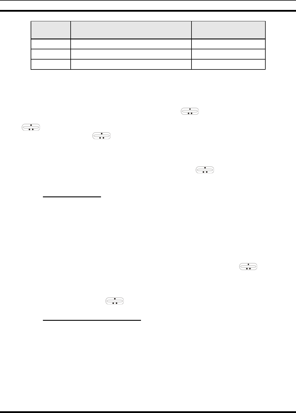
MM-014716-001
49
FEATURE
NUMBER POSSIBLE FEATURES STANDARD OR
OPTIONAL
33 P25 Common Air Interface Optional
34 Direct Frequency Entry Optional
38 Radio TextLink Optional
8.6 SYSTEM/GROUP/CHANNEL SELECTION
In the following description of SYSTEM/GROUP/CHANNEL SELECTION, the term group is used
for both group and channel.
The M7300 SYSTEM/GROUP/CHANNEL knob and the ramp control are programmable for
maximum flexibility. If the SYSTEM/GROUP/CHANNEL knob is assigned to select groups, then the
ramp control is assigned to select systems. If the SYSTEM/GROUP/CHANNEL knob is assigned
to select systems, then the ramp control is assigned to select groups. System, group, and channel
selection is the primary function for these controls.
Either systems or groups can also be selected by entering the select mode and following the selection
mode rules described earlier. The system select or group select modes are entered by pressing SYS or
GRP, respectively, from the standard receive mode. Using the ramp control after entering a
particular selection mode in this manner is the secondary function of these keys.
8.6.1 System Selection
Several methods, some of which depend on programming, can be used to select a new system. These
procedures are presumed to be starting from the normal receive display.
METHOD 1: If system selection is programmed to the SYSTEM/GROUP/CHANNEL knob, select a
system by turning the SYSTEM/GROUP/CHANNEL knob to the desired system
position. The display registers the new system name on line 1. If the wrap option is OFF
and the knob is moved to a position greater than the number of programmed systems, the
highest programmed system will remain selected.
METHOD 2: If system selection is programmed as the primary function of the ramp control,
select a system by pressing up or down to scroll through the system list. The display
registers the new system name on line 1.
METHOD 3: Press SYS to enter the system select mode and follow the selection mode rules detailed
earlier. Use the ramp control to scroll through the systems.
8.6.2 Group and Channel Selection
Several methods, some of which depend on programming, can be used to select a new group or channel.
These procedures assume starting from the normal receive display.
METHOD 1: If group selection is programmed to the SYSTEM/GROUP/CHANNEL knob, select a
group by turning the SYSTEM/GROUP/CHANNEL knob to the desired group. The
display registers the new group name on line 2. If the wrap option is OFF and the knob
is moved to a position greater than the number of programmed groups, the highest
programmed group will remain selected.
MM-014716-001
50
METHOD 2: If group selection is programmed as the primary function of the ramp control,
select a group by pressing up or down, to scroll through the group list. The display
registers the new group name on line 2.
METHOD 3: Press GRP to enter the group select mode and follow the selection mode rules detailed
earlier. Use the ramp control to scroll through different groups.
8.7 LAST SYSTEM/GROUP/CHANNEL RECALL
This feature, enabled through programming, allows the user to recall the last selected system/group after
an emergency or home function or system/group key function. For example, if the Home button (pre-
programmed) is pressed, the radio will go to the designated Home system/group or channel. If the Home
button is pressed again, the radio returns to the previous system/group or channel. At this time, the user
can toggle between the Home system/group or channel and the previous system/group or channel. The
operation is the same for the SG1-SG5 buttons.
8.8 DIGITAL VOICE OPERATION (PROVOICE)
8.8.1 Voice Modes
Each system (trunked or conventional) in the radio is programmed for no digital voice operation (analog
only) or digital voice format ProVoice. ProVoice programmed systems have three (3) different voice
modes: clear (analog), digital, and private. The voice modes are programmed on a per-group basis within
each trunked system and on a per-channel basis within each conventional system. A radio must be
equipped with the encrypt/decrypt option before it will operate in private mode.
Current ProVoice Conventional operation is for talk-around mode only.
Table 8-3: Transmit/Receive Mode Compatibility for ProVoice Operation
GROUP/CHANNEL
PROGRAMMING
(TRANSMIT)
CLEAR
RECEIVE DIGITAL
RECEIVE PRIVATE
RECEIVE
CLEAR Yes No No
DIGITAL Yes Yes No
PRIVATE Yes No Yes
8.8.2 Clear Modes
In Clear Mode, the radio transmits and receives only clear (analog) voice signals. These analog signals are
non-digitized and non-encrypted. Clear Mode transmissions can easily be monitored by unauthorized
persons. Groups or channels programmed for clear operation cannot transmit or receive unencrypted
digital or private messages.

MM-014716-001
51
8.8.3 ProVoice Digital Mode
ProVoice digital mode allows the radio to transmit and receive digitized voice signals. These digital
signals provide improved weak signal performance and they cannot be easily monitored with a standard
receiver. Groups and channels programmed for ProVoice digital operation transmit only digital signals.
Private calls cannot be received or transmitted when the radio is in ProVoice digital mode because the
radio does not know the cryptographic key used.
Message trunked group calls and individual calls will be answered back in the mode they were received,
assuming the call or hang time is still active. Individual, phone, all and emergency calls will be
transmitted clear if digital mode is disabled or inoperative.
• If receiving an analog message trunked call, the radio will respond in analog mode during the hang
time on the working channel.
• If receiving an analog I-Call, the radio will respond in analog mode during the hang time.
• When using the "WHC" feature to respond to an I-Call (after the hang time has expired), the call will
be transmitted in the mode defined by the system mode as programmed for the current system if the
ID being called is not in the I-Call list. If the ID is in the I-Call list, then the call will be transmitted as
defined by the I-Call mode programmed in the list for that ID.
DTMF
The overdial and hot keypad features for transmitting DTMF tones are not available while in ProVoice
Digital Mode.
ERROR Messages
If any of the following error messages are displayed, the radio was either programmed incorrectly or
needs servicing:
DSP ERR
ERR=xxxx DSP ERR DIGV ERR
Power Up Only
If the ProVoice circuit board is not responding, correctly, one of the following error messages will be
displayed and the radio needs servicing:
HARDWARE
ERR= 3X
3X will be a number between 30 and 38
8.8.4 ProVoice Private Mode
ProVoice private mode allows the radio to transmit encrypted messages and receive clear or private
transmissions. The radio will transmit private if the group/channel is programmed for private operation
and forced operation is pre-programmed.
If the radio was pre-programmed for auto-select, the radio will transmit in the following modes;
• If Private mode is enabled, transmissions are always in private mode.
MM-014716-001
52
• If Private mode is disabled and a private call is received, the Reply transmission will be in Private
mode if the transmission is made during the scan hangtime. If the reply transmission occurs after the
scan hangtime, the transmission will be in Clear mode.
When operating on a group or channel programmed for private mode, all transmissions will be private
transmissions and the radio will receive clear and private signals. If the selected group or channel is
programmed for auto-select capability, the mode can be toggled between private and clear with the OPT
or OPTION button. Radios programmed for forced private operation do not allow a change of the
transmit mode; therefore, the OPT or OPTION has no effect.
8.8.4.1 Displaying the Currently Used Cryptographic Key Number
To display the cryptographic key currently in use for either the system encryption key (for special call
such as individual, phone, all, agency or fleet) or the group/channel key (for group or conventional calls),
perform the following procedure (Not Available on Conventional radios):
1. Press the MENU button.
2. Use to select DISP KEY. Then press the MENU button.
3. Then use to toggle between displaying the system key or the group/channel key.
Table 8-4: Current Cryptographic Key Display
ENCRYPTION KEY
DISPLAYED MESSAGE DISPLAYED
System "SYS KEY"
"KEY = 1"
Group/Channel "GRP KEY"/"CHN KEY"
"KEY = 2"/KEY = 2"
8.8.4.2 Key Zero
All cryptographic keys can be zeroed (erased from radio memory) by pressing the CLR button (System
Model) or CLEAR (Scan Model) and while still pressing this button, press and hold the OPT button
(System Model) or OPTION (Scan Model). Press both buttons for 2 seconds. A series of warning beeps
will begin at the start of this 2-second period and then switch to a solid tone after the keys have been
zeroed. The display will indicate KEY ZERO.
If the cryptographic key(s) are zeroed, one or more keys must be transferred from the Key Loader into the
radio before private communications can continue. (Refer to Key Manager TQS3416 Administration and
Software Release Notes for further information.)
8.8.5 Private Operation
8.8.5.1 Receiving an Encrypted Call
When receiving, the radio automatically switches between clear or private operation. If the transmission
being received is an encrypted transmission, it will be decrypted, the receiver will unsquelch and the
message will be heard in the speaker. The selected group or channel must be programmed for private
operation and the correct cryptographic key must be loaded into the radio for this to occur.

MM-014716-001
53
8.8.5.2 Transmitting an Encrypted Call
1. Select the desired group or channel.
2. Place the radio in private mode by pressing the OPT button (System Model) or OPTION (Scan
Model).
If the last state of the radio was private mode, the private mode will be enabled on power up. In
addition, the private mode will be enabled if forced operation has been programmed in the radio
If a group or channel is not programmed for private mode operation, PVT DIS will be displayed if an
attempt is made to enable private transmit mode. It is not possible to operate on this group/channel in
private mode.
If the radio is programmed for forced private transmit operation, FRCD PVT will be displayed if an
attempt is made to disable private transmit mode. It is not possible to transmit on this group/channel
in clear mode.
If the radio does not have the correct encryption key loaded, NO KEY # will be displayed and the
call will not be transmitted.
3. Continue with standard transmission procedures. A private mode access tone will be heard when the
PTT button is pressed.
8.8.5.3 Scanned Group Calls
Receiving a scanned group call is the same as receiving a selected group call. During the scan hang time,
if the radio was programmed for auto-select, it will transmit back in the same mode it received the call.
For example, if a clear group is entered in the scan list, it will only receive clear calls. If the same group
was available in private and entered in the scan list, it can receive clear and private calls, provided auto-
select was programmed in the radio. The user can select transmitting on the scanned or selected group. If
a group is entered in the scan list more than once in different modes (clear, digital, private), only the first
occurrence of the group will be used.
8.8.6 Conventional Operation
8.8.6.1 Outside Address
The same outside address (works similar to Channel Guard operation) must be programmed in the
transmitting and receiving radios when ProVoice digital or private operation is enabled. If address is not
correct, the radios will not communicate.
8.8.6.2 Channel Guard
Channel Guard encode is transmitted on analog clear channels only. Channel Guard decode will operate
on either a clear or private channel. The exception is when G-STAR signaling is used (see G-STAR
paragraph).
8.8.6.3 G-STAR
When G-STAR is programmed on a private channel, the radio will transmit G-STAR in clear mode and
then switch to private for the voice portion of the call. If G-STAR is sent with Channel Guard, then both
are sent in clear mode and the radio switches to private mode. Emergency G-STAR data burst is
transmitted in clear mode.

MM-014716-001
54
8.9 MACRO KEY OPERATION
Macro key operation permits the user to accomplish a series of keystrokes with a single "macro"
keystroke. Up to ten (10) macro keys can be defined, each capable of executing up to twenty (20)
keystrokes, to any pushbutton input (i.e., keypad keys, buttons, etc.). Each macro key can be pre-
programmed to activate when pressed or when released.
A macro key can also be pre-programmed to change the keystroke sequence the next time the macro key
is activated.
For detail operation and assignment of macro keys, contact your communications supervisor or
administrator.
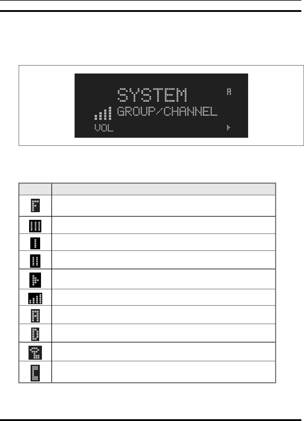
MM-014716-001
55
9 EDACS AND P25 TRUNKED OPERATION
9.1 RADIO STATUS ICONS
Status icons are indicators that show the various operating characteristics of the radio.
Figure 9-1: Typical Display
Table 9-1: Icons and Descriptions
ICON DESCRIPTION
Indicates the EDACS system is in Failsoft™ mode (if enabled through
programming).
Indicates selected group or channel is in scan list.
Indicates selected group or channel is programmed as Priority 1 in scan list.
Indicates selected group or channel is programmed as Priority 2 in scan list.
Scan mode enabled.
Volume bars – indicates relative volume level.
Indicates the current channel is set up as an analog channel.
Indicates the current channel is set up as a ProVoice channel.
Receiving or transmitting Encrypted Calls.
Special call mode (individual or telephone).

MM-014716-001
56
9.2 MESSAGES
During radio operation, various messages are displayed on either line 1 or line 2. Typical messages
include control channel status information, such as system busy or call denied, or messages associated
with the radio's operation, (i.e. volume adjust). These messages are described as follows:
Table 9-2: Display Messages
MESSAGE NAME DESCRIPTION
QUEUED Call Queued Indicates the system has placed the call in a request queue.
SYS BUSY System Busy Indicates the system is busy, no channels are currently available, the queue is full or
an individual call is being attempted to a radio that is currently transmitting.
DENIED Call Denied Indicates the radio is not authorized to operate on the selected system.
CC SCAN Control Channel Scan Indicates the control channel is lost and the radio has entered the Control Channel
Scan mode to search for the control channel.
WA SCAN Wide Area Scan Indicates the control channel is lost and the radio has entered the Wide Area Scan
mode to search for a new system (if enabled through programming).
*RXEMER* Receive Emergency Indicates an emergency call is being received. This message will be flashing on line 2.
*TXEMER* Transmit Emergency Indicates an emergency call has been transmitted. This message will be flashing on
line 2.
VOL=31 Volume Level Indicates the current volume level. The volume level display ranges from OFF (silent)
to 31 (loudest).
UNKNOWN Caller's ID Not
Received Indicates that an individual call is being received, but the caller's ID was not received.
TX DATA Transmit Data Indicates the radio is transmitting a data call.
RX DATA Receive Data Indicates the radio is receiving a data call. Displayed on line 2.
DATA OFF Data OFF Indicates the radio is in the data disabled state. Displayed on line 1.
DATA ON Data ON Indicates the radio has been toggled to the data enable state. Displayed for two
seconds on line 1 when toggled to enable state.
SYSC ON System Scan
Features ON Indicates the System Scan features are enabled.
SYSC OFF System Scan
Features OFF Indicates the System Scan features are disabled.
PA ON Public Address ON Indicates that the public address function of the radio is enabled.
PA OFF Public Address OFF Momentary (2 seconds) indicates that public address function of the radio was
disabled.
ALRM ON External Alarm
Enabled Indicates that the external alarm function of the radio is enabled.
ALRM OFF External Alarm
Disabled Momentary (2 seconds) indicates that the external alarm function of the radio was
disabled.
PVT DIS Private Mode
Disabled Indicates that private mode is disabled or no encryption key has been programmed for
the selected group/channel or special call.
FRCD PVT Forced Private
Operation Indicates that forced private operation has been pre-programmed into radio.
NO KEY # Encryption Key
Missing Flashing indicator indicates that no encryption key or an incorrect encryption key is
programmed into the radio.
BCKL=1-6 Backlight Indicates the display intensity and keypad backlight level.
GR Group ID Indicates that the call is a group call and is followed by the GID of the caller.
ID Individual ID Indicates the call is an individual call and the ID number of the caller, example "ID
2725."

MM-014716-001
57
MESSAGE NAME DESCRIPTION
WHC=1 Who Has Called
This display indicates the number from the Who Has Called list. Individual calls
received but not responded to are stored in a Who Has Called list. This list is
accessible by pressing the # key and then the INDV key after the Individual call has
timed out or the Clear button is pressed. This display is on line 2 and the LID of the
caller is displayed on the top line. Currently the list is not implemented and the display
will always be WHC=1.
PHONE Phone Call Displayed when a phone call is received from the site. It is displayed in line 1 of the
display. Line 2 of the display will contain the display *INDV* when line 1 contains this
message. The radio interprets a received phone call as an individual call.
CONV FS Conventional Failsoft Displayed when a failure of the EDACS system occurs. All communication will be in
conventional mode.
MENU Displayed when the menu key is pressed and remains displayed in line 1 until a menu
item is selected.
SYS=1-64 System = 1 - 64 The system number for the current base station of the system displayed in line 1. It is
displayed in line 2 of the display. Press the system key to obtain this display.
GRP=1-64 Group = 1 - 64
The group number of the group displayed in line 2 of display. It is displayed in line 1 of
the display. Press the group key to obtain this display. There are up to 48 groups
available (i.e. 3 banks of 16). The maximum number of groups programmed in a radio
is determined by the personality.
INDV=1-99 Individual = 1 - 99 Indicates which item in the individual call list is being displayed. It is displayed in line 2
of the display. The name or ID of the item in the list is displayed in line 1 of the
display.
PHN=1-99 Phone = 1 - 99 Indicates which item in the phone list is being displayed. It is displayed in line 2 of the
display. Line 1 of the display will be the last 3 characters of the list item contents.
SEL PHN Select Phone After pressing the PHN key, selecting an entry from the phone list by typing the entry
number will display this message on Line 1.
SEL INDV Select Individual ID Displayed on line 1 when an entry from the individual ID list is selected after pressing
the INDV key. The entry is a number between 1 and 32 inclusive.
SYS ALL System All Call Displayed on line 1 to indicate a system all-call has been received.
Ggg-v.vv Code Group and
Revision Number
This is code group and revision number that is displayed in line 2 when the menu item
“REVISION” is selected. The ‘gg’ is the group number of the software. The first ‘v’ is
the hardware version and ‘vv’ is the revision of the software.
*PHONE* Phone Call Displayed when an initiated phone call is in progress. This is displayed on line 2 of the
display.
NO ENTRY Indicates that there is no data stored in one of the programmable items in either the
phone list or individual call list. The user programmable items are items 1 through 10
in each list.
INV SYS Invalid System Displayed when the current system is an invalid type.
CHN=1-99 Channel = 1 - 99 Displayed on line 1 of the display. This is a conventional channel index displayed
when the group key is pressed.
FIX LIST Fixed List The Priority scan list is fixed and cannot be changed using the add or delete keys.
FIXED P1 Fixed Priority 1 The Priority 1 scan channel is fixed and cannot be changed using the add or delete
keys.
(c) 2004 Displayed in line 2 when the message ‘M/A-COM’ is displayed in line 1 while
displaying different items under the menu when “REVISION” is selected by the
operator.
EM Emergency Indicates an emergency has been declared by the LID that follows the display, “EM.”
An example of this is “EM 01201.”
*INDV* Individual Call Displayed in line 2 of the display when an individual call is in progress (trunked and
T99 modes only).
*GROUP* Group Call Indicates a group call is in progress and is displayed on line 1 of the display (trunked
and T99 modes only).
SPKR ON External Speaker ON Displayed when the external speaker is enabled.
SPKR OFF External Speaker
OFF Displayed when the external speaker is disabled.

MM-014716-001
58
MESSAGE NAME DESCRIPTION
BANK=1-8 The bank of keys that are going to be loaded when the keyloader loads encryption
keys. This is only valid for radios that support VGS, VGE, or DES encryption. It is
displayed on line 2 of the display when the encryption keyloader is connected.
REGR_0x Dynamic Regroup Indicates which group in the dynamic regroup operation has been enabled, where “x”
is a digit of 1 to 8.
KEY LOAD Displayed on line 1 of the display when the encryption keyloader is connected.
KEY ZERO Displayed on line 2 of the display when the reset and option buttons are pressed
simultaneously for approximately two seconds. The encryption keys are zeroed.
SYS KEY System Key Displayed on line 1 of the display in the display key mode of the menu. It is followed in
the second line with a key number “KEY = <1..7>”.
GRP KEY Group Key Displayed on line 1 of the display in the display key mode of the menu for trunked
systems only. It is followed in the second line with a key number “KEY = <1..7>.”
KEY=1-7 Displayed on line 2 of the display in the display key mode of the menu for
conventional systems when the “SYS KEY” or “CHN KEY” is displayed in line 1 and
for trunked systems when the “SYS KEY” or “GRP KEY” is displayed in line 1.
PRIMARY Displayed on line 1 of the display when the primary keys are enabled.
PRS NAME Personality Name Displayed on line 1 of the display under the revision selection of the menu. The
personality name is displayed on line 2 at the same time.
M/A-COM Displayed on line 1 of the display under the revision selection of the menu. The
copyright year is shown in line 2 of display at the same time “(c) 2007.”
9.3 ALERT TONES
The M7300 series mobile radio also provides audible alert tones or “beeps” to indicate the various
operating conditions. These alert tones can be enabled or disabled through programming.
Table 9-3: Alert Tones
NAME TONE DESCRIPTION
Call Originate A short mid-pitched tone. Sounds after keying the radio (Push-To-Talk button is
pressed). Indicates the radio has been assigned a
working channel
Autokey A mid-pitched tone.
After being placed in a queue or releasing the PTT
button prior to a working channel assignment, the site
calls the radio when a channel becomes available. At
this point, the radio automatically keys the transmitter
(autokey) for a short period to hold the channel. The
radio sounds a mid-pitched tone when it is clear to talk.
Immediately press the PTT button to keep the assigned
channel.
Call Queued A high-pitched tone.
Sounds after pressing the PTT button indicating the
system has placed the call request in the queue. The
receiving unit(s) also sound(s) the tones to indicate they
will receive a call shortly.
System Busy Three low-pitched beeps.
Sounds if the radio is keyed when the system is busy, if
no channels are available for sending the message, if
the call queue is full, or if an individual call is being
attempted to a radio that is transmitting.
Call Denied A low-pitched tone. Indicates the radio is not authorized on the system that
has been selected.
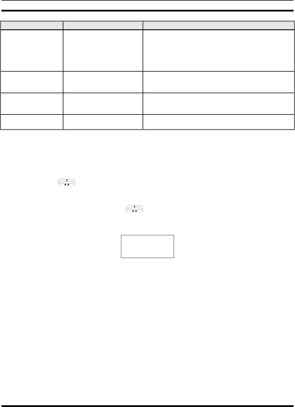
MM-014716-001
59
NAME TONE DESCRIPTION
Carrier Control Timer Five short high-pitched
warning tones followed by a
long low-pitched tone.
Sounds if the programmed time for continuous
transmission is exceeded. The transmitter will shut down
shortly after the alert, interrupting communications.
Release and re-key the PTT button to maintain
communications. This will reset the carrier control timer
and turn the transmitter back on.
Key Press Alert A short tone. Indicates a key has been pressed. A short low-pitched
tone indicates no action was taken because the key is
not active in the current mode.
Page (P25 T Only) Three high-pitched tones. In P25 trunked mode, if the receiving radio accepts a
page, both the receiving and transmitting radios emit
three high-pitched tones.
Out of Range One low pitched. Indicates the radio is in Wide Area Scan. Radio will
periodically beep when in Wide Area Scan.
9.4 MENU
The menu function accesses features that are not available directly from the keypad. The order and
specific number of menu items available is configurable through programming. Upon radio power up, the
menu item at the beginning of the menu list will always be displayed first. Subsequent access to the menu
function will return the last menu item that was shown in the display. To enter the menu mode, press
MENU. The ramp control, and CLR are used during the selection process. All of the selection
mode rules previously detailed apply to the menu item selection process with the exception of direct
access. The radio will continue to receive and transmit normally while in the menu function.
A new item is displayed by using the ramp control to scroll through the list in increasing and
decreasing order. The displayed menu item is made active by pressing MENU.
After entering the menu selection mode, the following generic display format will appear.
M E N U
Y Y Y Y Y Y Y Y
Line 1 indicates the radio is in the menu selection mode. Line 2 indicates the menu item (YYYYYYYY)
that is to be viewed or changed (some menu items provide radio information and do not have changeable
parameters).
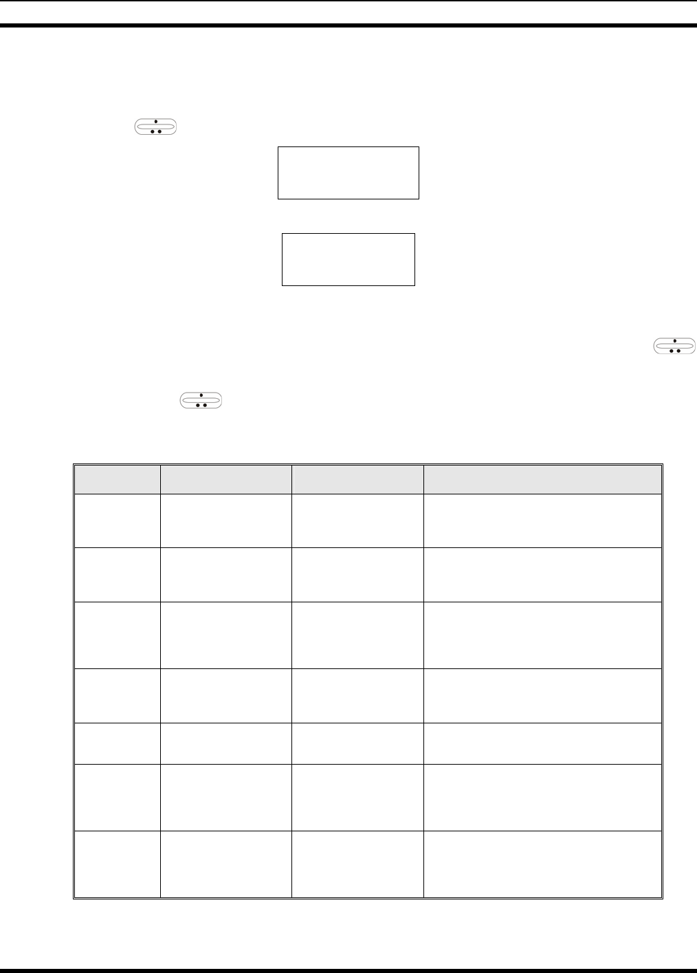
MM-014716-001
60
An example of the menu item selection process and menu item parameter change is detailed below for the
contrast menu item.
1. Press MENU to enter the menu mode.
2. Press the ramp control until the display shows:
M E N U
CONTRAST
3. Press MENU. The contrast menu item is activated and the display will be similar to the following:
CNTRST = X
Y Y Y Y Y Y Y Y
Line 1 shows the active menu item and its current parameter setting (XXX). Line 2 shows the
currently selected system or group name (YYYYYYYY).
4. The menu item's parameter setting shown in the display can now be changed by using the
ramp control to scroll through the list of parameter values. Once the desired setting is reached, press
MENU to store the value and return to the normal display. For menu items that display radio
information, use to scroll through a list of informational displays. The menu items are listed in
Table 9-4.
Table 9-4: Menu Item Information
FEATURE DISPLAY PARAMETER
SETTINGS COMMENT
Contrast Adjust
Menu Item:
CONTRAST
Once selected:
CNTRST=
1, 2, 3, 4, 5, 6, 7, 8 Selects the Contrast level.
Radio Revision
Information Menu item:
REVISION
Informational
displays only
(see radio); no user
selectable settings.
Selects the information display to view.
Phone Call
Menu item:
PHN CALL
Once selected: See
Telephone Interconnect
Call Section
Allows access to the Phone Call Feature.
Individual Call
Menu Item:
IND CALL
Once Selected: See
Individual Call Section
Allows access to the Individual Call Feature.
External Alarm Menu Item: EXTALARM
Once Selected:
EXTALARM ON, OFF EXTALARM replaces the system name on the
display as long as the external alarm feature is
enabled.
Public
Address
Menu item:
PUB ADDR
Once selected:
PA ON or
PA OFF
ON, OFF Public Address is toggled ON and OFF.
External Speaker
Menu item:
EXT SPKR
Once selected:
SPKR ON or
SPKR OFF
ON, OFF External Speaker is toggled ON and OFF.

MM-014716-001
61
FEATURE DISPLAY PARAMETER
SETTINGS COMMENT
Encryption Key
Loading
Menu item: KEYLOAD
Once selected:
KEY LOAD BANK = N Up to 8 banks of 7 keys Enables the radio to accept the loading of encryption
keys.
Display Current
Encryption
Key(s)
Menu item: DISP KEY
Once selected:
SYS KEY, GRP KEY or
CHN KEY and KEY = N
Displays current encryption key number.
Scan Menu item: SCAN ON, OFF Toggles scan function ON or OFF.
Private Mode Menu Item: PRIVATE
Once selected: PVT or key
light. ON, OFF Toggles private function ON or OFF.
Scan Add Menu item: SCAN ADD
Once selected: Proper scan
icon displayed. S, 2 or 1 Adds group or channel to scan list.
Scan Delete Menu item: SCAN DEL
Once selected: Scan icon
goes out. Deletes group or channel from scan list.
Scan Add/Delete Menu item: SCAN A/D
When selected: Toggles
through scan selections
Toggle sequence
S, 2, 1, S, ... Changes present group or channel to next scan
choice in scan list.
Last Scanned
Channel Recall
Menu Item: SCAN ADD
Press twice when actively
receiving; three times when
not receiving. Scan icon
displayed.
Changes the selected channel to the last scanned
channel.
Home group or
channel selection
Menu item: HOME
Once selected: Home group
or channel displayed. Changes to the group or channel defined for Home
function.
System select Menu item: SYS SEL
Once selected: SYS = n 1-64 = (n)umber of desired
system Displays the system selected.
External alarm #2 Menu item: EXTALRM2 ON, OFF Toggles external alarm #2 feature ON or OFF.
System and group
selection
Menu item: SYSGRP 1
Menu item: SYSGRP 2
Menu item: SYSGRP 3
Menu item: SYSGRP 4
Menu item: SYSGRP 5
Changes to the System & Group/Channel
programmed for SYSGRP 1-5.
Mute Menu item: MUTE ON, OFF Toggles the mute function ON or OFF to control the
audio output from the selected radio.
Mute #1 Menu item: MUTE 1 ON, OFF Toggles the mute 1 function ON or OFF on radio
#1.
Mute #2 Menu item: MUTE 2 ON, OFF Toggles the mute 2 function ON or OFF on radio
#2.
Multiple radio
operation Menu item: RADIO ON, OFF Toggles the currently selected radio.
Menu item: RADIO 1 ON, OFF Changes to radio #1.
Radio selection Menu item: RADIO 2 ON, OFF Changes to radio #2.
No Data Menu item: NO DATA ON, OFF Toggles data feature ON or OFF.
EDACS Convent-
ional Priority 1
Scan Menu item: ECP1SCAN ON, OFF Toggles this feature ON or OFF.
Group selection Menu item: GRP SEL
Once selected: GRP = n 1-64 = (n)umber of desired
group Displays the group selected.
Status Condition Menu item: STATUS Once
selected: ST =n 0-9 = (n)umber of pre-
programmed status Transmits the pre-programmed status message.
Message
Condition Menu item: MESSAGE
Once selected: MSG =n 0-9 = (n)umber of pre-
programmed messages Transmits the pre-programmed message.
Feature
Encryption
Display
Menu Item: FEATURES
Once selected:
See Feature Encryption
Display section
Informational displays only;
no user selectable settings
Indicates current features program- med into the
radio as well as certain information required to add
features to the radio (refer to the Table of Contents
for Feature Encryption Display.
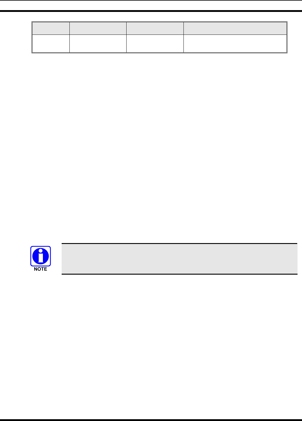
MM-014716-001
62
FEATURE DISPLAY PARAMETER
SETTINGS COMMENT
System Scan
Enable
Menu Item: SYS SCAN
Once selected: SYSC ON
or SYSC OFF ON, OFF System Scan features like ProScan are toggled ON
and OFF.
9.5 RECEIVING A CALL
1. Turn the radio on by rotating the POWER ON-OFF/VOLUME knob clockwise (out of detent). A
short alert signal (if enabled through programming) indicates the radio is ready to use.
2. The display shows the last selected or the power up (depending on programming) system and group
names. If the radio is unable to obtain a control channel, line 2 shows CC SCAN.
3. Adjust the POWER ON-OFF/VOLUME knob to the desired volume level.
4. Select the desired system and group. The display indicates the current system and group names.
5. The radio is now ready to receive calls.
6. When the radio receives a group call, it unmutes on the assigned working channel and the BSY
indicator comes on. Line 1 shows GR followed by the logical ID number (if received) of the unit
sending the message, or the associated name if the ID number is found in the individual call list.
9.6 SENDING A CALL
1. Turn the radio on and set the POWER ON-OFF/VOLUME knob to the desired volume level. Select
the desired system and group.
2. Press and hold the PTT button. The radio will display the system and group names and perform the
necessary signaling required to obtain a communication channel.
3. When the working channel is assigned, TX and BSY indicators are turned ON and a short beep is
sounded indicating communication can begin.
If two or more tones, or a high-pitched tone is heard, the system may be busy and the
call request has been placed in queue or the request has been denied for some reason.
Refer to the Section 9.3 for more details.
4. Hold the microphone approximately three inches from the mouth and speak in a normal voice.
5. Release the PTT button when the transmission is complete and listen for a reply.
9.7 CONVENTIONAL FAILSOFT
In the unlikely event of a failure of the EDACS system, communications can take place in conventional
failsoft mode. The radio will be automatically directed to a communications channel set up for this
purpose. During this mode of operation, the control unit will display CONV FS in the alphanumeric
display. An increase in activity on the channel during conventional failsoft operation may be noticed, so
be careful not to transmit until the channel is clear.
Operation during conventional failsoft will be the same as operation on a conventional system, except that
it will not be possible to select a communications channel, or use emergency and special call. When
trunking is restored, the radio will automatically be returned to normal operation.

MM-014716-001
63
Emergency and Special Call are not operational during conventional failsoft. In
addition, the GRP control will not operate.
9.8 EMERGENCY OPERATION
The radio's ability to declare an emergency, clear an emergency, remain locked on an emergency and
group, and the emergency audio and display freeze can each be enabled or disabled through
programming. When an emergency is declared scanning will stop and will restart only after the
emergency has been cleared.
9.8.1 Receiving an Emergency Call
When receiving an emergency call from the selected group and system, an alert beep is heard and the
BSY indicator lights. The message *RXEMER* flashes in the display on line 2 until the emergency
condition is cleared. Follow standard emergency procedures.
9.8.2 Declaring an Emergency
To send an emergency call to the selected system and group (or on an optionally pre-programmed
emergency group), proceed as follows:
1. Press and hold the red emergency button for approximately one second. (This time is programmable
and therefore could be longer or shorter. Check with the system administrator.) The radio will
transmit an emergency call request with the radio ID until an emergency channel assignment is
received.
2. When the working channel assignment is received, the radio sounds a single beep (Autokey alert
tone) indicating it is ready for voice transmission. *TXEMER* flashes on line 2 in the display until
the emergency is cleared.
3. Press PTT and speak into the microphone in a normal voice.
4. Release PTT when the transmission is complete and listen for a reply.
5. The emergency can be cleared by pressing and holding the CLR button followed by pressing the red
emergency button then releasing both buttons.
9.9 SYSTEM SCAN OPERATION
The radio can be programmed with the following System Scan features. These features are automatically
enabled upon radio power up. A key or menu option is also defined to allow the System Scan features to
be toggled during radio operation. This is covered in the Menu Selection and Pre-Programmed Keypad
Key sections. The System Scan state will be maintained through system changes but will default to ON at
power up.
9.9.1 Wide Area System Scan
The M7300 Series mobile radio can be programmed for wide area system scan operation for multi-site
applications. Upon the loss of the currently selected system's control channel, radios can be programmed
to automatically scan the control channels of other systems. If a new control channel is found, the radio
will switch to the new system and sound an alert tone.

MM-014716-001
64
9.9.2 ProScan
The radio can be programmed for ProScan™ system scan operation for multi-site applications depending
on the version of radio flash code. ProScan provides the radio with the ability to select a new system for
the radio to communicate on, when the selected system drops below a predefined level. This is
accomplished by enabling each radio to analyze the signal quality of its current control channel and
compare it with the signal quality of the control channel for each site in its adjacency scan list. (The signal
quality metric used for the ProScan algorithm is based on a combination of both Received Signal Strength
Indicator [RSSI] and Control Channel Verification [CCV] measurements.) When the selected system’s
signal quality level degrades below a pre-programmed level, the radio will begin to look for a better
control channel. Once a control channel that exceeds the pre-programmed parameters is found, the radio
will change to the new system and emit a tone. If the control channel is completely lost the radio, will
enter Wide Area System Scanning and search the programmed adjacent systems until a suitable control
channel is found.
9.9.3 Priority System Scan
The radio can also be programmed for Priority System Scan. (To ensure that this feature operates
correctly, the control channel of the priority system must be located on channel one unless you are using
the ProScan algorithm.) The priority system is the desired or preferred system. While receiving the
control channel of the selected system, the radio will periodically leave the selected system and search for
the control channel of the priority system at a programmable rate. The programmable rate is defined by
the value in the Priority Scan Time control, (unless the ProSound/ProScan algorithm is enabled as
explained below). This priority scan timer is reset each time the PTT button is pressed or when a call is
received. If the priority system control channel is found, or meets the predefined ProScan criteria, the
radio will automatically switch to the priority system.
9.9.4 When Wide Area System Scan Is Enabled
If the radio cannot find the control channel of the selected system and begins Wide Area System Scan
(WA Scan), the radio will only scan for the priority system control channel if the priority system is in the
WA Scan list.
9.9.5 When ProScan Is Enabled
The radio monitors the priority system and will switch to the priority system if the priority system meets
the criteria defined in the “ProSound/ProScan Options” dialog box. If ProScan is enabled, the rate at
which the radio will scan for the priority system is defined by the System Sample Time control.
9.9.6 Menu Selection
Press MENU and then use the ramp control to scroll through the selections until SYS SCAN is
displayed. Then press MENU to toggle the System Scan state. The SYSC ON or SYSC OFF display
message is displayed for two seconds to show the new state.
9.9.7 Pre-Programmed Keypad Key
Press the pre-programmed key and the SYSC ON or SYSC OFF display message is displayed for two
seconds to show the new state.

MM-014716-001
65
9.10 GROUP SCAN OPERATION
Only Groups that are part of the radio's scan list will be scanned. Groups are added to the scan list on a
per system basis through programming, the radio keypad, or both, dependent upon programming. This
scan list can be changed by the user from the keypad unless programmed otherwise. Each system's group
scan list is retained in memory when the radio is turned off. The M7300 Series mobile radio can also be
programmed to provide Trunked Priority Group Scan capability, which operates similar to priority scan in
Conventional mode.
The following is a description of programmable scan features that should be helpful in understanding the
Group Scan Operation of the radio:
Scan Hang Time - the delay time the radio waits before resuming scan after the push-to-talk is released
or after the carrier has dropped a channel.
TX Select - the group the radio will transmit on while scanning. The radio is programmed to transmit on
either the scanned group or the selected group.
Scan List (privileges) - this feature allows or prohibits scan list changes by the user.
P1 Programming - priority group programming is accomplished by one (and only one) of three methods:
• From the keypad, where the Priority programming is not fixed and does not follow the selected
channel,
• Priority 1 group programming follows the selected channel, or
• Priority 1 group programming is fixed during PC programming and cannot be changed by the user.
P1 Always Scan - determines if the Priority 1 Group will always be scanned, regardless of the scan state
set by the user.
9.10.1 Adding Groups to a Scan List
1. With scan operation turned off, select the desired group to add to the selected Trunked system group
scan list.
2. Press (+) or (-) with to display the current priority status of the group on line 1 for a time-out
period.
3. While the status is displayed, press (+) with to add the group to the scan list. is displayed.
4. Press (+) with a second time to set the group to Priority 2. is displayed.
5. Press (+) with a third time to set the group to Priority 1. is displayed in column 1, line 1.
The priority level selection sequence only advances the group to next higher priority level and stops
at priority level 1. To select a lower priority level, the group must be deleted from the scan list and
then added back to the scan list. Each new group added to the scan list starts at the lowest priority. If
the Priority 1 and Priority 2 groups are already set and a new group is assigned as Priority 1 or
Priority 2, the previously assigned group will change to non-priority scanning.
9.10.2 Deleting Groups from a Scan List
1. With scan operation turned off, select the desired group to delete from the selected trunked system's
group scan list.
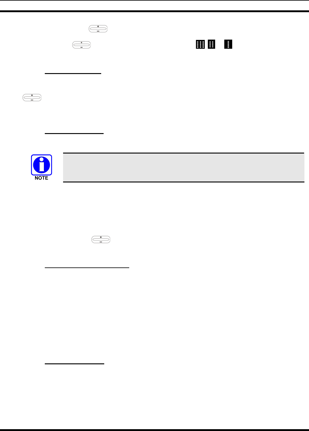
MM-014716-001
66
2. Press (+) or (-) with . The current scan status of the group is displayed for a time-out period.
3. Press (-) with to delete the group from the scan list. , or turns off. Any group that is
not in a trunked system group scan list will show a “blank” when it is the selected channel.
9.10.3 Nuisance Delete
A group can also be deleted from the scan list, if it is not the currently selected group by pressing (-) with
during scan operation while the radio is displaying the unwanted group. The group will be deleted
from the system's group scan list in the same manner as if done using the steps above. Deletions
performed in this manner will not remain deleted if the radio is turned off and then back on.
9.10.4 Turning Scan On
1. Toggle scan operation by pressing SCAN. The SCAN indicator turns on when the radio is scanning.
The SCAN key light blinks when temporarily disabled. Scanning will stop while
microphone is off-hook if the hookswitch feature is enabled through programming.
2. When a group on the scan list receives a channel assignment, the radio unmutes on the assigned
channel, the BSY indicator comes on and the received scan group is displayed.
• The radio will continue scanning if a new group is selected when scan is on.
• Pressing the PTT button when scan is on will cause the radio to transmit on the displayed group
or on the currently selected group depending on programming.
• Pressing up with when scan is on will cause the radio to recall the scanned group that was
last received. This group is recalled for a period equal to the scan hang time.
9.10.5 Priority Group Scanning
When scan is enabled and the Priority 1 and Priority 2 groups have been identified, the radio will listen to
calls on those groups and the selected group. While receiving a scanned group call, the radio will continue
to monitor the selected Priority 1 and Priority 2 groups and will drop the call if the selected group or other
higher priority call becomes active. During a Priority 2 call the radio will continue to monitor for a
Priority 1 group call.
The radio will monitor for Agency and Fleet calls that correspond to the Agency and Fleet associated with
the Priority 1 and Priority 2 groups. Priority Agency and Fleet calls will be indicated by displaying
AGENCY or FLEET on the System line of the display and associated Priority 1 or 2 group on the Group
line of the display.
9.10.6 Turning Scan Off
Toggle scan operation off by pressing SCAN. The radio will resume operation on the selected group.
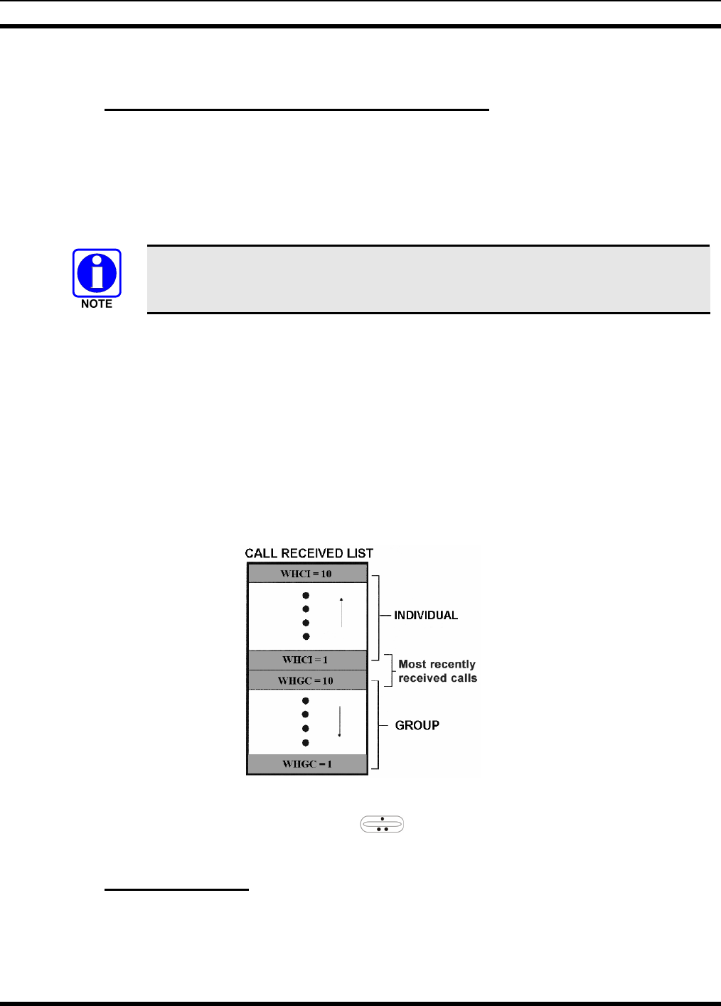
MM-014716-001
67
9.11 INDIVIDUAL CALLS
9.11.1 Receiving and Responding to an Individual Call
When the radio receives an individual call (a call directed only to the user's radio), it unmutes on the
assigned working channel and turns on the BSY indicator. Line 1 shows “ID” followed by the logical ID
number of the radio sending the message, or the associated name if the ID number is found in the
individual call list. The individual call indicator will display *INDV* on line 2. The radio can be
programmed to ring when an individual call is received. If enabled, the ring begins five seconds after the
caller unkeys and will continue until the PTT button, the CLR button, or IND is pressed.
Hookswitch functions the same as CLR key in I-CALL, phone call, and menu modes.
If a response is made to the call prior to the programmed call-back time-out, the call will automatically be
directed to the originating unit. If a response is not made before the call-back time-out, the radio will
return to normal receive mode, but * WHC * will be displayed. If the caller's ID is not received,
UNKNOWN will display for the duration of the call and there will be no call-back hang time.
To respond after the call-back time-out, press the IND key. The radio's display will show the callers ID on
the first line and WHCI=1 on the second line. Pressing the PTT button at this point will initiate an
individual call back to the original caller. (If the last call was a group call, the display will show
WHCG=1. Pressing the PTT button will place the call as an individual call.)
The radio stores the IDs of the last 10 callers in the Calls Received List as shown. Individual calls are
stored in the top half of the list (1-10) and group calls are stored in the bottom half of the list (1-10). The
most recent call is stored in position 1, the second most recent call is stored in position 2, etc.
To access the list, press the IND key twice. Use to scroll through the list. Press the MENU key to
display the time elapsed since the call was received.
9.11.2 Call Storage Lists
There are two lists available for call storage in the radio, the calls received list (1-10) and the personality
list (1-99 as defined by the user). When the individual call mode is entered by pressing IND, the calls
received list is available. The user can toggle to the personality list by selecting any key other than DIS or
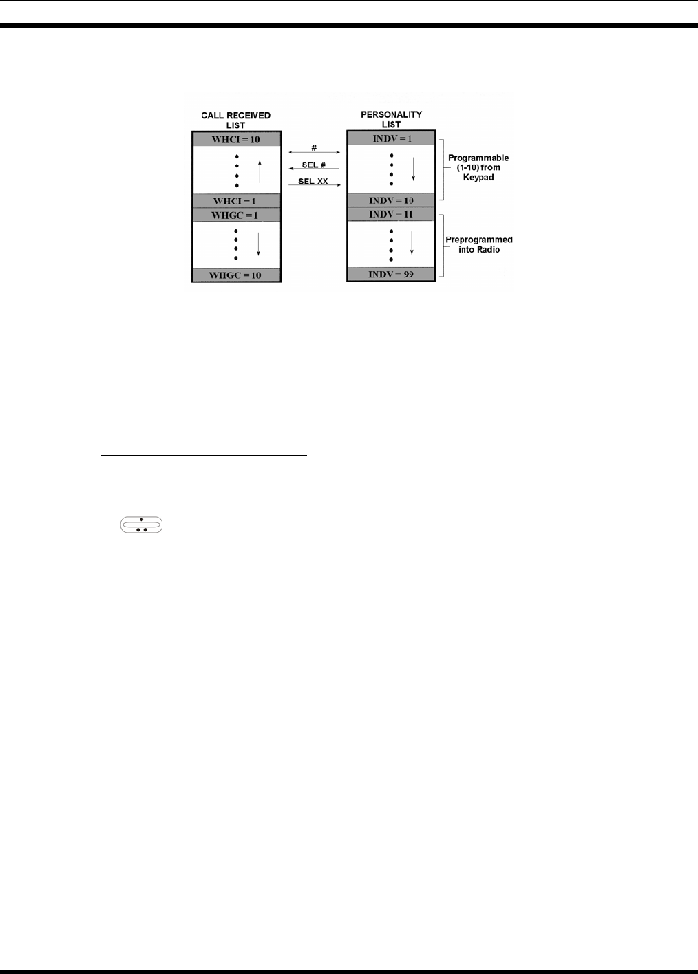
MM-014716-001
68
toggle between the two lists by pressing the IND key. If wrap is enabled, the calls received list wraps on
itself and not into the other list.
The saved call list shows all ten storage locations. If no calls have been received, the saved call list will be
empty and the pre-stored list will be available upon entering the individual call mode.
When in the saved call list, pressing MENU toggles the time stamp ON and OFF. The time stamp
indicates how long ago the call was received. The display indicates this information as HH:MM:SS where
HH = hours, MM = minutes and SS = seconds.
When in the pre-stored list, pressing MENU toggles the Logical IDentification (LID) ON and OFF.
9.11.3 Sending an Individual Call
The following procedures describe how to initiate and complete an individual call.
1. To select a previously stored individual, select the I-Call mode from the menu or press IND followed
by the ramp control to scroll through the list of stored individuals. The selection mode rules
apply. While in the individual call list, the menu key will toggle the display between the call name
and the unit ID number. If the individual is not stored in this list but the individual’s unit ID is known,
it can be entered directly from the keypad.
2. Press the PTT button; the radio performs the necessary signaling to obtain a communication channel.
When the signaling is complete and the radio is clear to transmit, TX indicator turns ON and the
channel access tone sounds. Line 1 shows the called individual's name if found in the list of stored
individuals or ID followed by the logical ID number of the unit being called. The message *INDV*
displays on line 2. Proceed with the message.
9.12 SCAT OPERATION
A SCAT™ (Single Channel Autonomous Trunking) System operates with the same set of features as a
standard EDACS system. The only significant user change relates to the BSY indicator. Since only one
channel, operating as both control and working channel, exists in a SCAT System, the BSY indicator will
be ON when the SCAT channel is in the working channel mode. When the transmission on the channel is
completed, the indicator turns OFF and indicates the return of SCAT control channel signaling.
MM-014716-001
69
9.13 TELEPHONE INTERCONNECT CALLS
9.13.1 Receiving a Telephone Interconnect Call (Trunked Mode Only)
Receiving a telephone interconnect call is identical to receiving an individual call. See the DTMF
Overdial Operation section if access to services requiring "over-dial" is needed. Overdial operations are
available for any special call whether it is an individual call or a telephone interconnect call.
9.13.2 Sending a Telephone Interconnect Call (Trunked Mode Only)
Use the following procedures to initiate and complete a Telephone Interconnect call:
1. To select a previously stored phone number, select phone call mode from the menu, press PHN and
use the ramp control to scroll through the list of stored phone numbers. The selection mode
rules apply. While in the phone call list, the MENU key will toggle the display between the phone
call name and the phone call number. If the phone number is not stored in this list but the phone
number is known, it can be entered directly from the keypad. If necessary, a pause can be entered by
pressing and holding 0-9, *, or # until an underscore appears in the display.
2. Press and release the PTT button; the radio performs the necessary signaling to obtain a
communication channel. When the signaling is complete and the radio is clear to transmit, TX
indicator turns on and the channel access tone sounds. Line 1 shows the accompanying name if
selected from the list of stored numbers or the phone number if entered directly. The message
*PHONE* is displayed on line 2. The radio then automatically transmits the programmed number
stored in the special call queue.
3. Telephone ringing will be heard. When someone answers the phone, press the PTT button and speak
into the microphone. Release the PTT button to listen to the caller. Unsuccessful interconnect
signaling returns the radio to the normal receive mode and the number remains displayed until the
special call is cleared by pressing the CLR button or the time-out expires or another group or system
is selected.
4. To terminate the call, momentarily press the CLR button.
The M7300 Series mobile radio is capable of half-duplex conversation only. The
caller’s message can only be sent if the PTT button is pressed (the radio is
transmitting) and the caller can only be heard by the person being called when the PTT
is released (the radio is receiving).
9.13.3 DTMF Overdial/Conventional Mode Telephone Interconnect
Once the radio has established a connection to the public telephone system, it may be necessary to "over-
dial" more digits to access banking services, answering machines, credit card calls or other types of
systems that require DTMF (Dual-Tone Multi-Frequency) access digits. Overdial operation can also be
used to initiate a telephone interconnect call via DTMF signaling if a dial tone has already been accessed
on the system. This is the method that is used for making a telephone interconnect call while operating in
the conventional mode but will also function in trunked mode if a dial tone is directly accessible.
Telephone numbers and other number sequences for overdialing can be stored in the phone list when
programming the radio or stored by the operator in the first ten phone list entries. These numbers are
accessed by pressing PHN then following the selection mode rules.
The following steps are required to dial these numbers:

MM-014716-001
70
1. Follow the procedure in Sending a Telephone Interconnect Call (Trunked Mode Only) to
establish a connection to the telephone system or consult the system administrator for the procedure
to access a dial tone on the trunked or conventional system.
2. Overdial numbers are transmitted using either method as follows:
METHOD 1: Press and hold PTT while entering the overdial number sequence from the keypad.
This method sends DTMF tones during individual, telephone interconnect, trunke
d
group, or conventional channel calls. Anytime the PTT button is pressed and held,
the keypad is enabled for DTMF entry.
METHOD 2: Press PHN to enter the overdial select/entry mode and follow the selection mode
rules to call up a stored number from the phone list or to directly enter the overdial
digits. Press PTT to send the overdial sequence once. If the number needs to be
transmitted again it must be selected or entered again (this prevents unwante
d
numbers from being sent the next time the PTT button is pressed during the call).
This overdial select/entry mode remains active until the call is dropped, cleared, or MENU is pressed. The
overdial select/entry mode can be re-entered if the call is still active by pressing PHN.
9.13.4 Programmable Entries
Individual call ID numbers, telephone numbers and other number sequences for overdialing are stored in
the special call lists when programming the radio. The first ten entry locations of these lists can be
changed by the radio operator. The keypad is used when adding, changing and storing numbers in these
entry locations.
Use the following procedure to store a number in one of the first ten entries of a special call list:
1. Press IND or PHN to enter the individual call list or the phone call list. The selection mode rules
apply.
2. Scroll through the list using the ramp control until one of the first ten entries is reached. NO
ENTRY is displayed if the location is empty.
3. Enter the desired number. If necessary, a pause can be entered by pressing and holding 0-9, (*), or (#)
until an underscore appears in the display. The individual call list entries will accept up to 5 digits.
The phone call list entries accept a combination of up to 31 digits and pauses.
4. Press and hold MENU until the display changes indicating that the number has been stored.
5. Repeat the steps above if the number stored in an entry location needs to be changed.
9.14 MOBILE DATA
The M7300 Series mobile radios, when operating in the EDACS configuration, permit either voice or data
calls to be transmitted or received. The radio can handle only one type of call at a time; however,
selection of either data or voice is selected transparently by the operator through normal usage of the
radio. Data communications is not supported in the conventional mode.
The mobile radios can be connected to Mobile Data Terminals (MDT) or to a host computer. Any RS-232
compatible device that supports the Radio Data Interface (RDI) protocol (Version 1.91 or greater) can be
connected to the mobile radio. Support for MDTs or host computers is a programmable option per radio.
Additionally, radios programmed for host computers can also be programmed for data only operation (no
voice calls transmitted or received).

MM-014716-001
71
Turn power to the radio OFF before connecting or disconnecting any cables, including
the data cable. Also, turn power to the radio OFF when docking or undocking a
connected laptop computer. Failure to turn the power OFF can damage the radio,
requiring service by a M/A-COM approved service center.
9.14.1 Displays
The following will be displayed on the control unit during the various states of data mode of operation.
TX DATA Displayed on bottom line of display when the radio is transmitting a data call.
RX DATA Displayed on bottom line of display when the radio is receiving a data call.
DATA OFF Displayed on top line of display when the radio is in the data disabled state.
DATA ON Displayed for two seconds on top line of display when the radio is toggled to the data
enabled state.
9.14.2 DATA OFF Operation
The radio can be placed in the data disable state by any of the following methods. When the data state is
disabled, the control unit displays "DATA OFF" on the top line. An ongoing data call is allowed to
complete except when an emergency is declared.
• Removing the microphone from the hookswitch (hookswitch option must be enabled by pre-
programming).
• Declaring an emergency (not to be used unless an actual emergency condition exists). Alert tone will
sound.
• Pressing the OPT button (System Model) or OPTION (Scan Model) (pre-programmed). Alert tone
will sound.
• Selecting the function using the MENU button (pre-programmed).
9.14.3 DATA ON Operation
The data state is enabled by one of the following (depending on how it was disabled). “DATA ON” will
be displayed top line of display for 2 seconds then the display returns to normal.
• Replacing the microphone into the hookswitch (going on-hook). Only valid if the “DATA OFF”
operation was entered by removing the microphone from the hookswitch (going off-hook).
• Clearing an emergency, but valid only if an emergency caused “DATA OFF” operation.
9.14.4 Exiting Data Calls
Under normal conditions, the radio enters the scan lockout mode and returns to the control channel after
completion of a data call (transmit or receive). If, during a data call, one of the following conditions
occurs, the data call is immediately terminated and the radio performs the desired function:
• The PTT is activated.
• The PTT is in Public Address mode.
• An emergency is declared by pressing the pre-programmed emergency button.
• A group or system change is made.

MM-014716-001
72
9.14.5 Scan Lockout Mode
Following the transmission or reception of a data call, if scan is enabled, scanning will stop temporarily
(duration pre-programmed). During this time the scan LED will flash to indicate that scan is enabled but
temporarily suspended. This mode is normally exited when the pre-programmed time expires; however,
the following actions will terminate the scan lockout mode before the timeout is completed.
• The CLR (System Model) or CLEAR (Scan Model) button is pressed.
• The PTT is pressed.
• A group or system change is made.
• Enter phone call mode.
• Enter individual call mode.
• A new emergency assignment has been received.
• The PTT is pressed in Public Address Mode.
• An emergency is declared or cleared.
• Microphone is removed from hookswitch (OFF-hook).
• Receiving an individual or phone call.
• Receiving an Agency, Fleet or System All Call.
• Pressing the SCAN button to turn scan ON or OFF.
9.14.6 Data Lockout Mode
The data lockout mode is a pre-programmed mode when the radio will not respond to any data channel
assignments and prevents receive data calls from interrupting voice calls. Transmit data calls will still be
initiated when needed by the operator. After a pre-programmed time, the radio will respond to receive
data calls; however, the following conditions will clear the data lockout mode:
• The CLR (System Model) or CLEAR (Scan Model) button is pressed.
• Transmitting a data call.
• Changing a system.
• An emergency is declared.
• Pressing the PTT while in Public Address mode.
• Turning scan ON with the SCAN button.
9.15 STATUS/MESSAGE OPERATION
Status and message operation is possible with either the Scan or System version of the M7300 Series
mobile radio unit. The following procedure is applicable for the System version. For operation with the
Scan version, the four primary keycaps must be reconfigured and pre-programmed for status/message
operation.

MM-014716-001
73
9.15.1 Status Operation
Status operation permits the transmission of a pre-programmed status condition to the EDACS site.
To send a status condition, press the STS button (keylight comes on) then press one of the number
buttons (0-9) to select the pre-programmed status. If no status has been programmed for the selected
number button, the radio will display NO ENTRY and the radio will sound a low tone. A valid selection
will permit the status text to appear in the display for a pre-programmed time. After the time-out expires
or the MENU button has been pressed (the MENU button will override the time-out period), the status is
selected and will be transmitted to the site or stored in the radio memory where it can be polled by the site
at a future time. If the site receives the status properly, when transmitted or polled by the site, a high-
pitched tone sounds and the keylight associated with that status will remain lit. If the site does not receive
the status properly, a low-pitched tone sounds and the keylight associated with the status will blink.
If an incorrect status was selected or the incorrect number button was pressed, the status can be changed
during the pre-programmed time-out period by pressing another number button. The status selection can
also be cancelled by pressing the CLR button prior to the time-out period.
To view the currently selected status after it has been transmitted, press the STS button. If the status was
not sent successfully to the site, the text associated with the status will flash in the display.
The radio can also be pre-programmed to redesignate the keypad buttons for ST0 thru ST9 to send status
condition. In this configuration the radio status operation will operate as previously described except the
STS button is not required. The keylight associated with ST0 thru ST9 will indicate which status is
selected.
9.15.2 Message Operation
Message operation permits the transmission of a pre-programmed message text to an EDACS site.
To send a message, press the MSG button (keylight comes on) then press one of the number buttons (0-9)
to select the pre-programmed message text. If no message text has been programmed for the selected
number button, the radio will display NO ENTRY and a low-pitched tone sounds. A valid selection will
permit the message text to appear in the display for a pre-programmed time. After the time-out expires or
the MENU button has been pressed (the MENU button will override the time-out period), the message
text is selected and will be transmitted to the site. If the site receives the message properly when
transmitted, a high pitched tone sounds and the MSG keylight remains lit. If the site does not receive the
message properly, a low-pitched tone sounds and the MSG keylight will blink.
If an incorrect message text was selected or the incorrect number button was pressed, the message text
can be changed during the pre-programmed time-out period by pressing another number button. The
message text selection can also be cancelled by pressing the CLR button prior to the time-out period.
To view the currently selected message text after it has been transmitted, press the MSG button and then
the CLR button prior to the time-out period. If the message text was not sent successfully to the site, the
text associated with the message will flash in the display.
9.16 EDACS CONVENTIONAL P1 SCAN
This feature permits the radio user to scan a pre-programmed conventional system and channel as a
Priority 1 (P1) channel while the radio is selected for EDACS trunked system. If activity is detected on
the conventional P1 channel, the radio will unmute and remain on this conventional channel for the
programmable hang time.
The radio must be pre-programmed to designate a button for scan ON/OFF operation.

MM-014716-001
74
9.17 DYNAMIC REGROUP OPERATION
Dynamic regroup operation permits multiple talk groups (up to eight) to be added to a radio via the
Communications Systems Director (CSD). The radio must be pre-programmed to respond to regrouping.
Dynamic regrouping will not be activated in a radio until an activation message is sent by the system
manager. Each radio that receives and acknowledges regrouping instructions is successfully regrouped.
Pressing and holding the CLEAR (Scan Model) or CLR (System Model) button for 2.5 seconds toggles
the user into and out of the dynamic regroup group set. A double beep will sound for entry or exit. The
display will indicate REGR_0x where "x" is a digit of 1 to 8 indicating the group when dynamic regroup
has been enabled by the user. If the radio is in dynamic regroup and the user selects a group that has not
been regrouped, the display will show NO ENTRY. The radio will be prevented from transmitting and
receiving calls in this condition except for scanned groups.
9.17.1 Emergency Operation
If the pre-programmed group set on the currently selected system contains an EMER/HOME group and
the radio is in dynamic regroup, the radio will exit dynamic regroup and declare the emergency on the
HOME group. If no EMER/HOME group is present, the radio will declare the emergency on the currently
selected dynamic regroup group.
9.18 PAGE (P25 TRUNKED ONLY)
Page sends a PING message to a radio and functions similar to Individual Call.
The following procedures describe how to initiate and complete a Page.
1. To select a previously stored individual, select the Page mode from the menu followed by the
ramp control to scroll through the list of stored individuals. The selection mode rules apply. While in
the individual call list, the menu key toggles the display between the call name and the unit ID
number. On System model radios, the individual’s unit ID can also be entered directly from the
keypad.
2. Press the PTT button; the radio performs the necessary signaling on the control channel. On the
calling radio, line 1 shows the called individual's name if found in the list of stored individuals or ID
followed by the logical ID number of the unit being called. If the receiving radio receives the Page
and responds, both radios will emit three high-pitched tones. The receiving radio will also display
PAGE and the ID of the calling radio.
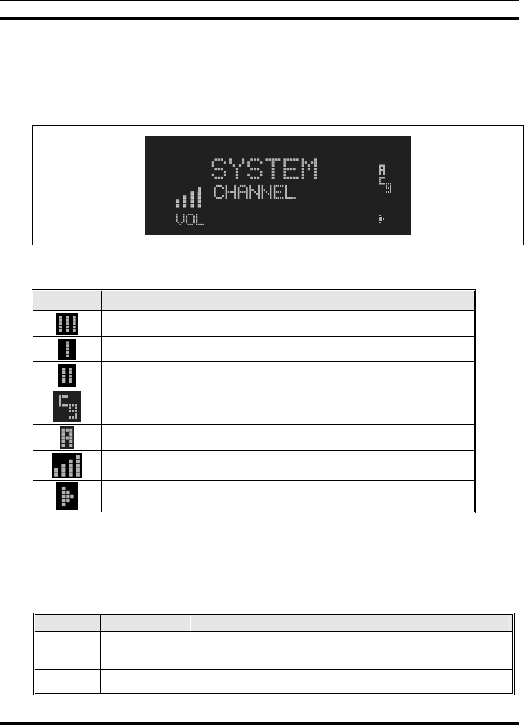
MM-014716-001
75
10 CONVENTIONAL OPERATION
10.1 RADIO STATUS ICONS
Status icons are indicators that show the various operating characteristics of the radio. The icons appear
on the first line of the display.
Figure 10-1: Typical Display
Table 10-1: Icons and Descriptions
ICON DESCRIPTION
Indicates selected group or channel is in scan list.
Indicates selected group or channel is programmed as Priority 1 in scan list.
Indicates selected group or channel is programmed as Priority 2 in scan list.
Indicates a conventional channel enabled with Channel Guard Function.
Indicates the current channel is set up as an analog channel.
Volume bars – indicates relative volume level.
Scan mode enabled.
10.2 MESSAGES
During radio operation, various messages are displayed on either line 1 or line 2. Typical messages
include control channel status information, such as system busy or call denied, or messages associated
with the radio's operation, (i.e. volume adjust). These messages are described as follows:
Table 10-2: Display Messages
MESSAGE NAME DESCRIPTION
TALKARND Talk-around Indicates the radio is operating on conventional channels in talk-around mode (no repeater).
VOL=31 Volume Level Indicates the current volume level. The volume level display ranges from OFF (silent) to 31
(loudest).
UNKNOWN Caller's ID Not
Received Indicates that an individual call is being received, but the caller's ID was not received.

MM-014716-001
76
MESSAGE NAME DESCRIPTION
T99 ON Type 99 Decode ON Indicates the Type 99 Decode feature is enabled.
T99 OFF Type 99 Decode OFF Indicates the Type 99 Decode feature is disabled.
PA ON Public Address ON Indicates that the public address function of the radio is enabled.
PA OFF Public Address OFF Momentary (2 seconds) indicates that public address function of the radio was disabled.
ALRM ON External Alarm Enabled Indicates that the external alarm function of the radio is enabled.
ALRM OFF External Alarm
Disabled Momentary (2 seconds) indicates that the external alarm function of the radio was disabled.
NO KEY # Encryption Key Missing Flashing indicator indicates that no encryption key or an incorrect encryption key is
programmed into the radio.
BCKL=1-6 Backlight Indicates the display intensity and keypad backlight level.
GR Group ID Indicates that the call is a group call and is followed by the GID of the caller.
MENU Displayed when the menu key is pressed and remains displayed in line 1 until a menu item is
selected.
SYS=1-64 System = 1 - 64 The system number for the current base station of the system displayed in line 1. It is displayed
in line 2 of the display. Press the system key to obtain this display.
SEL PHN Select Phone After pressing the PHN key, selecting an entry from the phone list by typing the entry number
will display this message on Line 1.
Ggg-v.vv Code Group and
Revision Number This is code group and revision number that is displayed in line 2 when the menu item
“REVISION” is selected. The ‘gg’ is the group number of the software. The first ‘v’ is the
hardware version and ‘vv’ is the revision of the software.
NO ENTRY Indicates that there is no data stored in one of the programmable items in either the phone list
or individual call list. The user programmable items are items 1 through 10 in each list.
INV SYS Invalid System Displayed when the current system is an invalid type.
CHN=1-99 Channel = 1 - 99 Displayed on line 1 of the display. This is a conventional channel index displayed when the
group key is pressed.
FIX LIST Fixed List The Priority scan list is fixed and cannot be changed using the add or delete keys.
FIXED P1 Fixed Priority 1 The Priority 1 scan channel is fixed and cannot be changed using the add or delete keys.
(c) 2004 Displayed in line 2 when the message ‘M/A-COM’ is displayed in line 1 while displaying
different items under the menu when “REVISION” is selected by the operator.
EM Emergency Indicates an emergency has been declared by the LID that follows the display, “EM.” An
example of this is “EM 01201.”
*INDV* Individual Call Displayed in line 2 of the display when an individual call is in progress (trunked and T99
modes only).
*GROUP* Group Call Indicates a group call is in progress and is displayed on line 1 of the display (trunked and T99
modes only).
SPKR ON External Speaker ON Displayed when the external speaker is enabled.
SPKR OFF External Speaker OFF Displayed when the external speaker is disabled.
BANK=1-8 The bank of keys that are going to be loaded when the keyloader loads encryption keys. This is
only valid for radios that support VGS, VGE, or DES encryption. It is displayed on line 2 of
the display when the encryption keyloader is connected.
KEY LOAD Displayed on line 1 of the display when the encryption keyloader is connected.
KEY ZERO Displayed on line 2 of the display when the reset and option buttons are pressed
simultaneously for approximately two seconds. The encryption keys are zeroed.
SYS KEY System Key Displayed on line 1 of the display in the display key mode of the menu. It is followed in the
second line with a key number “KEY = <1..7>”.
KEY=1-7 Displayed on line 2 of the display in the display key mode of the menu for conventional
systems when the “SYS KEY” or “CHN KEY” is displayed in line 1 and for trunked systems
when the “SYS KEY” or “GRP KEY” is displayed in line 1.
PRIMARY Displayed on line 1 of the display when the primary keys are enabled.
PRS NAME Personality Name Displayed on line 1 of the display under the revision selection of the menu. The personality
name is displayed on line 2 at the same time.
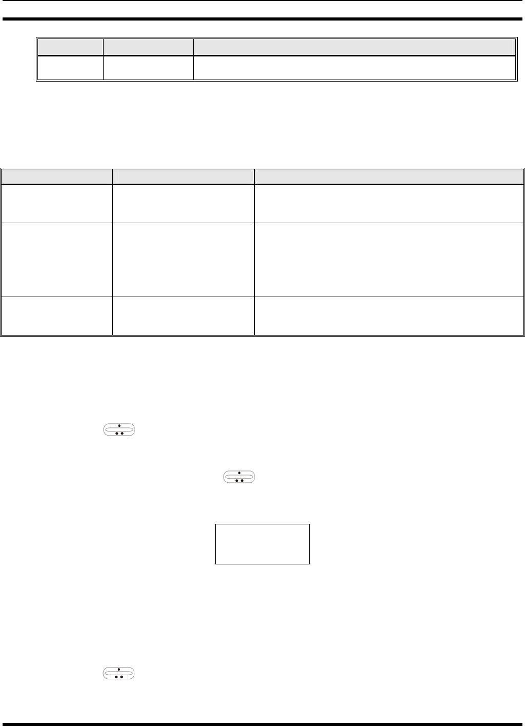
MM-014716-001
77
MESSAGE NAME DESCRIPTION
M/A-COM Displayed on line 1 of the display under the revision selection of the menu. The copyright year
is shown in line 2 of display at the same time “(c) 2007.”
10.3 ALERT TONES
The M7300 series mobile radio also provides audible alert tones or “beeps” to indicate the various
operating conditions. These alert tones can be enabled or disabled through programming.
Table 10-3: M7300 EDACS Mode Alert Tones
NAME TONE DESCRIPTION
Call Originate A short mid-pitched tone. Sounds after keying the radio (Push-To-Talk button is
pressed). Indicates the radio has been assigned a
working channel
Carrier Control Timer Five short high-pitched
warning tones followed by a
long low-pitched tone.
Sounds if the programmed time for continuous
transmission is exceeded. The transmitter will shut down
shortly after the alert, interrupting communications.
Release and re-key the PTT button to maintain
communications. This will reset the carrier control timer
and turn the transmitter back on.
Key Press Alert A short tone. Indicates a key has been pressed. A short low-pitched
tone indicates no action was taken because the key is
not active in the current mode.
10.4 MENU
The menu function accesses features that are not available directly from the keypad. The order and
specific number of menu items available is configurable through programming. Upon radio power up, the
menu item at the beginning of the menu list will always be displayed first. Subsequent access to the menu
function will return the last menu item that was shown in the display. To enter the menu mode, press
MENU. The ramp control, MENU, and CLR are used during the selection process. All of the
selection mode rules previously detailed apply to the menu item selection process with the exception of
direct access. The radio will continue to receive and transmit normally while in the menu function.
A new item is displayed by using the ramp control to scroll through the list in increasing and
decreasing order. The displayed menu item is made active by pressing MENU.
After entering the menu selection mode, the following generic display format will appear.
M E N U
Y Y Y Y Y Y Y Y
Line 1 indicates the radio is in the menu selection mode. Line 2 indicates the menu item (YYYYYYYY)
that is to be viewed or changed (some menu items provide radio information and do not have changeable
parameters).
An example of the menu item selection process and menu item parameter change is detailed below for the
contrast menu item.
1. Press MENU to enter the menu mode.
2. Press the ramp control until the display shows:
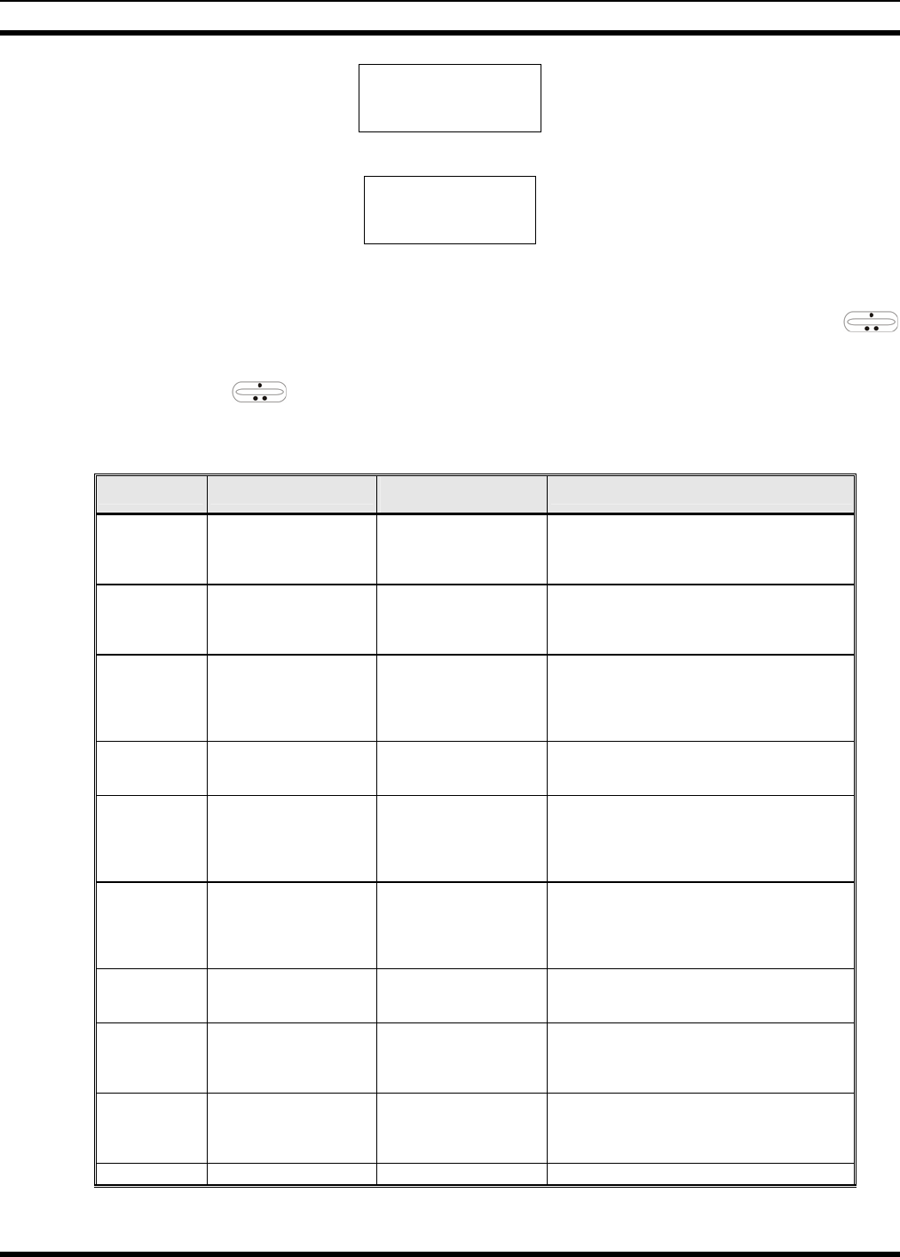
MM-014716-001
78
M E N U
CONTRAST
3. Press MENU. The contrast menu item is activated and the display will be similar to the following:
CNTRST = X
Y Y Y Y Y Y Y Y
Line 1 shows the active menu item and its current parameter setting (XXX). Line 2 shows the
currently selected system or group name (YYYYYYYY).
4. The menu item's parameter setting shown in the display can now be changed by using the
ramp control to scroll through the list of parameter values. Once the desired setting is reached, press
MENU to store the value and return to the normal display. For menu items that display radio
information, use to scroll through a list of informational displays. The menu items are listed in
Table 9-4.
Table 10-4: Menu Item Information
FEATURE DISPLAY PARAMETER
SETTINGS COMMENT
Contrast Adjust
Menu Item:
CONTRAST
Once selected:
CNTRST=
1, 2, 3, 4, 5, 6, 7, 8 Selects the Contrast level.
Radio Revision
Information Menu item:
REVISION
Informational
displays only
(see radio); no user
selectable settings.
Selects the information display to view.
Phone Call
Menu item:
PHN CALL
Once selected: See
Telephone Interconnect
Call Section
Allows access to the Phone Call Feature.
External Alarm Menu Item: EXTALARM
Once Selected:
EXTALARM ON, OFF EXTALARM replaces the system name on the
display as long as the external alarm feature is
enabled.
Public
Address
Menu item:
PUB ADDR
Once selected:
PA ON or
PA OFF
ON, OFF Public Address is toggled ON and OFF.
External Speaker
Menu item:
EXT SPKR
Once selected:
SPKR ON or
SPKR OFF
ON, OFF External Speaker is toggled ON and OFF.
Encryption Key
Loading
Menu item: KEYLOAD
Once selected:
KEY LOAD BANK = N Up to 8 banks of 7 keys Enables the radio to accept the loading of encryption
keys.
Display Current
Encryption
Key(s)
Menu item: DISP KEY
Once selected:
SYS KEY, GRP KEY or
CHN KEY and KEY = N
Displays current encryption key number.
Front Panel
Squelch Adjust
Menu item:
SQUELCH
Once selected:
SQLCH=xx
1-16 Allows setting of squelch.
Scan Menu item: SCAN ON, OFF Toggles scan function ON or OFF.

MM-014716-001
79
FEATURE DISPLAY PARAMETER
SETTINGS COMMENT
Scan Add Menu item: SCAN ADD
Once selected: Proper scan
icon displayed. S, 2 or 1 Adds group or channel to scan list.
Scan Delete Menu item: SCAN DEL
Once selected: Scan icon
goes out. Deletes group or channel from scan list.
Scan Add/Delete Menu item: SCAN A/D
When selected: Toggles
through scan selections
Toggle sequence
S, 2, 1, S, ... Changes present group or channel to next scan
choice in scan list.
Last Scanned
Channel Recall
Menu Item: SCAN ADD
Press twice when actively
receiving; three times when
not receiving. Scan icon
displayed.
Changes the selected channel to the last scanned
channel.
Home channel
selection
Menu item: HOME
Once selected: Home group
or channel displayed. Changes to the group or channel defined for Home
function.
System select Menu item: SYS SEL
Once selected: SYS = n 1-64 = (n)umber of desired
system Displays the system selected.
External alarm #2 Menu item: EXTALRM2 ON, OFF Toggles external alarm #2 feature ON or OFF.
System selection
Menu item: SYSGRP 1
Menu item: SYSGRP 2
Menu item: SYSGRP 3
Menu item: SYSGRP 4
Menu item: SYSGRP 5
Changes to the System & Group/Channel
programmed for SYSGRP 1-5.
Mute Menu item: MUTE ON, OFF Toggles the mute function ON or OFF to control the
audio output from the selected radio.
Mute #1 Menu item: MUTE 1 ON, OFF Toggles the mute 1 function ON or OFF on radio
#1.
Mute #2 Menu item: MUTE 2 ON, OFF Toggles the mute 2 function ON or OFF on radio
#2.
Multiple radio
operation Menu item: RADIO ON, OFF Toggles the currently selected radio.
Menu item: RADIO 1 ON, OFF Changes to radio #1.
Radio selection Menu item: RADIO 2 ON, OFF Changes to radio #2.
Talkaround
feature
Menu item: TALKARND
Once selected:
TALKARND on line 1 ON, OFF Toggles talkaround ON or OFF (transmit frequency
changed to receive frequency).
Channel selection Menu item: CHN SEL
Once selected: CHN = n 1-99 = (n)umber of desired
channel Displays the conventional channel selected.
Feature
Encryption
Display
Menu Item: FEATURES
Once selected:
See Feature Encryption
Display section
Informational displays only;
no user selectable settings
Indicates current features program- med into the
radio as well as certain information required to add
features to the radio (refer to the Table of Contents
for Feature Encryption Display.
Type 99 Decode
Enable
Menu Item: T99 ENAB
Once selected:
T99 ON or T99 OFF ON, OFF Type 99 Decode is toggled ON and OFF.
System Scan
Enable
Menu Item: SYS SCAN
Once selected: SYSC ON
or SYSC OFF ON, OFF System Scan features like ProScan are toggled ON
and OFF.
10.5 RECEIVING A CALL
1. Turn the radio on by rotating the POWER ON-OFF/VOLUME knob clockwise (out of detent). A
short alert signal (if enabled through programming) indicates the radio is ready to use.
2. Adjust the POWER ON-OFF/VOLUME knob to the desired volume level.
3. Select the desired conventional system and channel. The display indicates the current conventional
system and channel names.

MM-014716-001
80
4. The radio is now ready to receive calls.
5. When the radio receives a call (and the correct encoding is decoded, if programmed and enabled), it
unmutes on the channel and the BSY indicator comes on.
10.6 SENDING A CALL
1. Turn ON the radio and set the POWER ON-OFF/VOLUME knob to the desired volume level.
Select the desired conventional system and channel.
2. Ensure that the channel is not busy by pressing the CLR button to briefly disable any channel
decoding and unmute the receiver or observe the unlit BSY indicator. If the Channel Busy Lockout
feature is programmed for the selected channel, the radio will not transmit when the channel is busy.
3. Press and hold the PTT button. The TX indicator will turn on and a short beep sounds (if
programmed) indicating that communication can begin.
4. Hold the microphone approximately three inches from the mouth and speak in a normal voice.
5. Release the PTT button when the transmission is complete and listen for a reply.
10.7 EMERGENCY OPERATION
If enabled, G-STAR emergency signaling can be transmitted when operating in the conventional mode.
This G-STAR signaling will transmit 5 times with a delay between each transmission. To send an
emergency call on the selected conventional system and channel (or on an optionally pre-programmed
conventional emergency system and channel), proceed as follows:
Press and hold the red Emergency button for approximately one second (this time is programmable and,
therefore, could be longer or shorter; check with the system administrator). The radio turns on the TX
indicator and proceeds to transmit the pre-programmed G-STAR emergency signaling sequence.
G-STAR is programmed to transmit in one of the following methods:
METHOD 1: G-STAR is transmitted on the selected channel. If the channel is changed the emergency
signaling will continue to be transmitted on the newly selected channel.
METHOD 2: Same as METHOD 1 but the radio will lock on to the currently selected channel. Any
attempts to change the system or channel will be disabled.
METHOD 3: G-STAR is transmitted on a pre-programmed conventional emergency system and
channel regardless of the selected channel. In this case the selected channel is available
for voice transmission and the radio will periodically change to the pre-programmed
emergency system and channel to send the emergency signaling and then change back to
the selected channel.
METHOD 4: Same as METHOD 3 but the radio will lock on to the pre-programmed emergency
system and channel. Any attempts to change the system or channel will be disabled.
The emergency state can be cleared by turning the radio OFF and then back ON.
10.7.1 Using 5-Tone Signaling to Declare an Emergency
If 5-Tone signaling is defined for emergency declaration in place of G-STAR emergency signaling, a pre-
programmed tone sequence will be transmitted instead of the G-STAR sequence. This emergency
declaration functions as the G-STAR emergency in all other respects.

MM-014716-001
81
10.7.2 Tone Encode Transmission
In conventional mode, two keys can be defined to be tone encode triggers. If either one of the pre-
programmed tone encode triggers is pressed, a pre-programmed tone sequence will be transmitted on the
current system and channel. (See Section 10.7 if the emergency key is used.) The TX indicator will light
during tone transmission and a beep will sound at the end of the transmission. If enabled, audible side
tones will be heard in the radio speaker as well. If PTT is pre-programmed as one of the triggers, the
microphone will become active for voice communication after the tone sequence is complete.
Tone encode will be transmitted with Channel Guard if one is defined, and tones are always transmitted in
clear voice mode, even if the channel is set for digital or private (see VOICE MODES). Digital or private
voice transmission will resume normally after the tone transmission.
10.8 SCANNING CONVENTIONAL CHANNELS
Channels, which have been previously added to the scan list on a per system basis, can be scanned. The
selected channel is scanned (if enabled through programming) whether or not it is in the scan list. Each
conventional system's channel scan list is retained in memory when the radio is turned OFF.
The scan rate will vary depending upon the number of channels in the scan list and whether or not the
radio is programmed to scan for channels with decoding enabled. Fewer channels will result in a faster
scan rate. If programmed for dual-priority scan operation, the priority-one, priority-two and the remaining
scan list channels are scanned. Once a signal is detected and the correct encoded squelch signal is
decoded (if programmed), the radio receives the message and displays the received scan channel. At the
same time, scanning continues on the priority-one and priority-two channels. If a priority-one or priority-
two channel carrier, regardless of encoded squelch decoding, is detected while a non-priority channel is
being received, the display name is updated and the received channel is switched to the priority channel.
Scanning of the priority-one channel will continue if a message is being received on the priority-two
channel.
While receiving a call on a non-priority or a priority two channel, the radio periodically checks the
priority one and two channels. If Scan with Channel Guard is enabled, the radio will use Channel Guard
to decide whether to unmute on a priority channel. The radio will stop, on squelch detection, on a priority
channel. In normal operation, the radio will unmute only on detecting the correct Channel Guard;
otherwise, it will remain muted until the priority channel call and hang time have ended. An optional
feature allows the radio to continue scanning upon the detection of the wrong Channel Guard on a priority
channel. The user can then select the rate at which this channel is scanned until the call ends.
10.8.1 Adding Channels to a Scan List
1. With scan operation turned OFF, select the desired channel to add to the selected conventional system
channel scan list.
2. Press (+) or (-) with to display the current scan status on line 1 of the display for a time-out
period.
3. While current scan status is displayed, press (+) to add the channel to the scan list. is displayed.
This sets the selected channel for non-priority scanning.
4. Press (+) again to set the channel for Priority 2 (P2) scanning and is displayed.
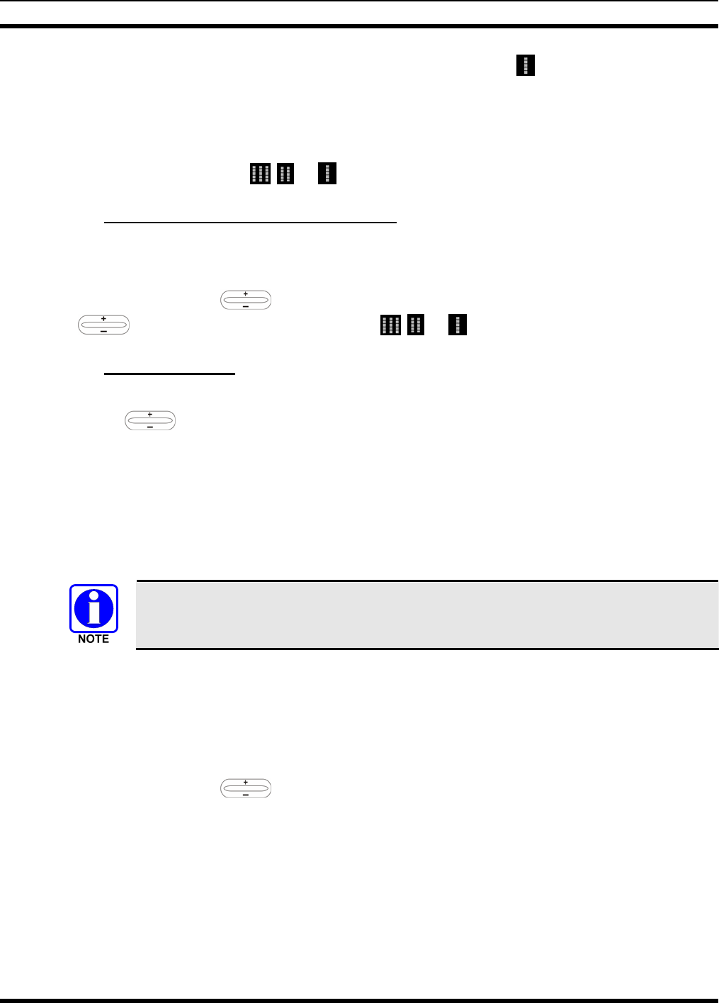
MM-014716-001
82
5. A third press of (+) sets the channel for Priority 1 (P1) scanning and is displayed on line 1. If the
P1 or P2 channels are already set and a new channel is then assigned as the P1 or P2 channel, the
previously assigned priority channel will change to non-priority scanning. The priority setting
selection sequence is set and stops at P1, therefore the channel must be deleted from the scan list by
pressing (-) before the channel is set to a previous priority setting. Any channel that is in a system's
channel scan list will show , , or when it is the selected channel.
10.8.2 Deleting Channels From A Scan List
1. With scan operation turned OFF select the desired channel to delete from the selected conventional
system's channel scan list.
2. Press (+) or (-) with . The current status is displayed for a time-out period. Press - with
to delete the channel from the scan list. , , or will turn OFF.
10.8.3 Nuisance Delete
A channel can also be deleted from the scan list, if it is not the currently selected channel, by pressing
down with twice during scan operation while the radio is displaying the unwanted channel. The
channel will be deleted from the conventional system's channel scan list in the same manner as if done
using the steps above. Deletions done in this manner will not remain deleted if the radio is turned OFF
and then back ON.
10.9 TURNING SCAN ON
1. Toggle the scan operation ON by pressing SCAN. The SCAN indicator will turn ON when the radio
is scanning.
Scanning will stop while the microphone is off-hook if the hookswitch feature is enabled
through programming.
2. When a channel on the scan list receives a channel assignment, the radio unmutes on the assigned
channel, BSY indicator comes ON and the received scan channel is displayed.
• The radio will continue scanning if a new channel is selected when scan is ON.
• Pressing the PTT button when scan is ON will cause the radio to transmit on the displayed
channel or to the currently selected channel depending on programming.
• Pressing (+) with when scan is ON causes the radio to recall the scanned channel that
was last received. This channel is recalled for a period equal to the scan hang time.
10.10 TURNING SCAN OFF
Toggle the scan operation OFF by pressing SCAN. The radio will resume operation on the selected
channel.
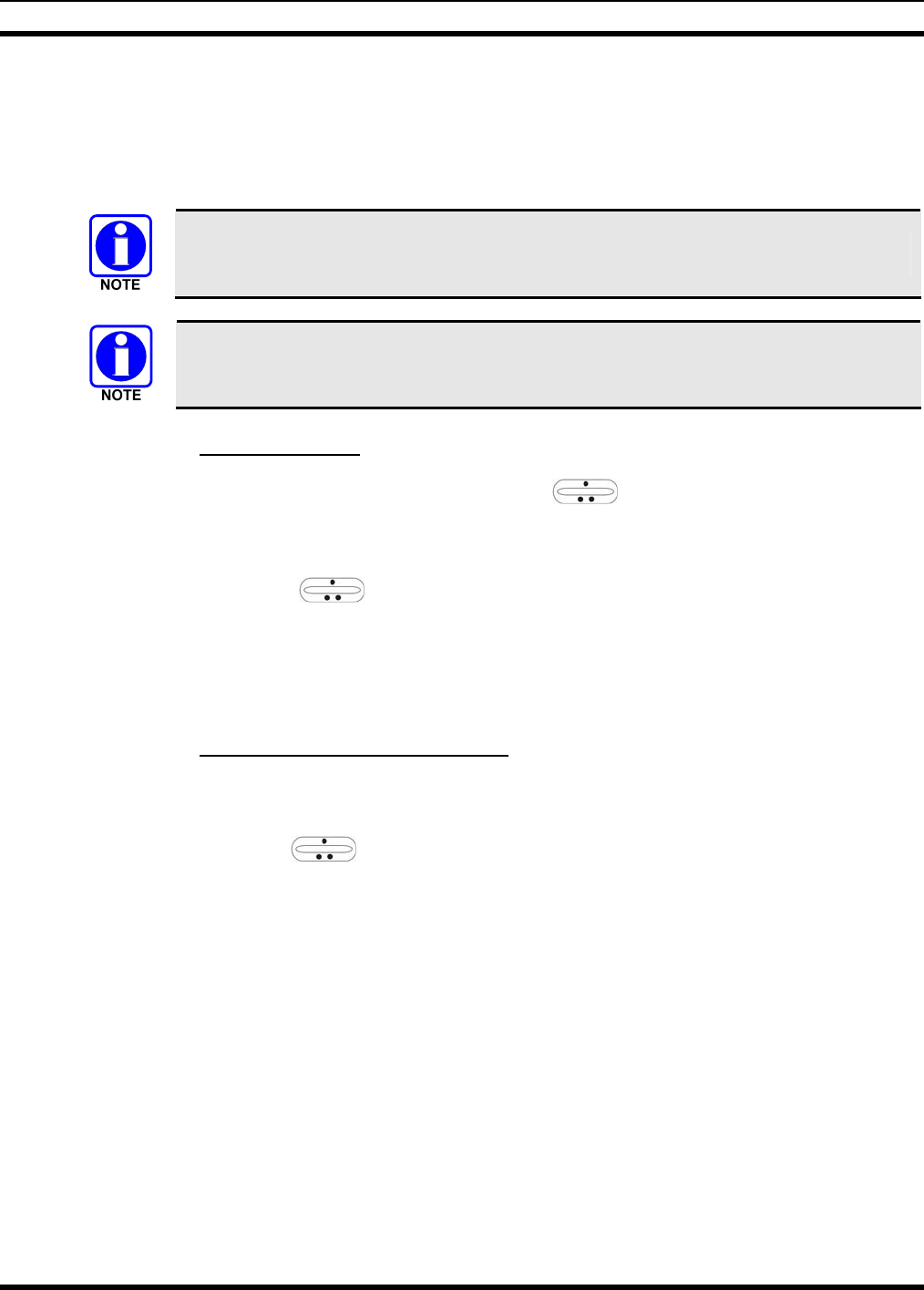
MM-014716-001
83
10.11 SQUELCH ADJUST
In the conventional mode of operation, the squelch can be re-adjusted in the MENU selection mode or
from a front panel key on the keypad that has been pre-programmed. A default value of 9, or any user
level between 1 and 16, can be selected using programming software. The user can change this setting
either of two ways from the front panel keys.
A value of 16 requires a strong signal to open squelch, a value of 2 requires a very weak
signal to open squelch, and a value of 1 is open squelch.
When the squelch adjust feature is activated, Channel Guard, T99 decode, and Scan are
disabled. When the squelch adjust feature is exited, Channel Guard, T99 decode, and
Scan are restored to their previous states.
10.11.1 Menu Selection
1. Press the MENU key and then use the RAMP control to scroll through the selections until
SQUELCH is displayed. Then press MENU (select) again.
2. The display will show SQLCH=xx, where "xx" is the value between 1 and 16.
3. Use the RAMP control to scroll through the values. Then press the MENU (select) key to
save the new value after the display time-out (2 seconds). The displayed value will be selected and
saved.
4. If the MENU or CLR key is pressed before the time-out, the menu feature will exit and the squelch
level will not be updated. The original value will be restored.
10.11.2 Pre-Programmed Keypad Key
1. Press the pre-programmed key and the display will indicate SQLCH=xx, where "xx" is the value
between 1 and 16.
2. Use the RAMP control to scroll through the values. Then press MENU to save the new value
or wait for the display time-out (2 seconds). The displayed value will be selected and saved.
3. If the CLR key is pressed before the time-out, the squelch level will not be updated and the original
value will be restored.
10.12 TYPE 99 DECODE
If the Type 99 Decode Option has been pre-programmed, individual selective calling is possible. The
radio can now decode individual, group or supergroup paging calls. Two sets of Type 99 paging codes
must be pre-programmed into the radio. When the radio decodes an appropriate Type 99 code sequence,
an alert tone and visual indicator is provided to the user. The receiver then operates as a noise squelched
unit until Type 99 is reset. Type 99 decode continues to operate during this noise squelched period. The
appropriate Type 99 alert tone will sound again if it detects a valid two-tone sequence.
Type 99 operation can be reset manually or automatically (pre-programmed). Manual reset is achieved by
briefly pressing CLR, if programmed. Automatic reset, if enabled, occurs after a 30 second interval
following the most recent decode of a Type 99 tone sequence. Hookswitch (pre-programmed) can also
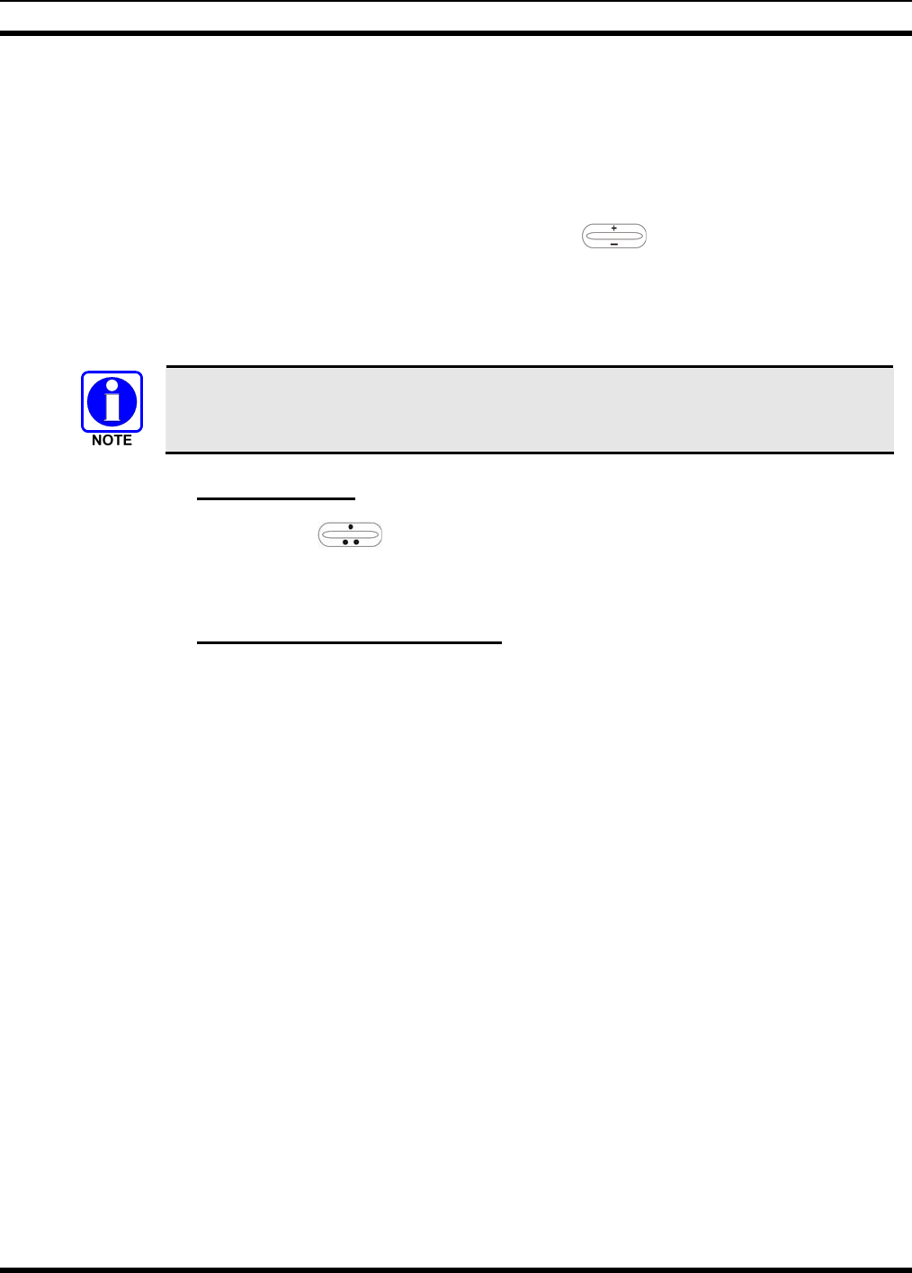
MM-014716-001
84
enable or disable Type 99 decode. The pre-programmed key light will blink when Type 99 is disabled by
the hookswitch.
Type 99 decode will continue to be active while the radio's CLR button is pressed. This allows the user to
monitor calls and still be alerted when a call is directed to the user. While the user continues to press
CLR, the user will hear both calls and all Type 99 tone signals. If CLR is pressed for longer than two (2)
seconds, Type 99 decode will either be disabled or re-enabled depending upon its present state.
To check the Type 99 enable status, press the Scan Add/Delete ramp control. The current status
of Type 99 decode will be displayed for a time-out period.
If a Horn Alert Option is installed and enabled with the Type 99 Decode Option, the radio can beep the
vehicle horn when a Type 99 call is received. This option permits alerting persons out of the vehicle when
a call is received.
Type 99 is automatically disabled when Scan is enabled.
10.12.1 Menu Selection
Press MENU and then use the ramp control to scroll through the selections until T99 ENAB is
displayed. Then press MENU to toggle the Type 99 decode state. The T99 ON or T99 OFF display
message is displayed for two seconds to show the new state.
10.12.2 Pre-Programmed Keypad Key
Press the pre-programmed key and the T99 ON or T99 OFF display message is displayed for two
seconds to show the new state.
10.13 DIRECT MODE OPERATION
The direct mode (or talk-around) provides short range, line of sight communications. One of the buttons
on the control unit must be pre-programmed for this feature to function.
1. Make sure the radio is ON and then select the desired conventional system and channel.
2. Press the pre-programmed button to toggle the talk-around function ON.
3. Ensure that the channel is not busy by pressing the CLR (System version) or CLEAR (Scan version)
to briefly disable any channel decoding and unmute the receiver or observe the unlit BSY indicator. If
the Channel Busy Lockout feature is programmed for the selected channel, the radio will not transmit
when the channel is busy.
4. Press and hold the PTT button. The TX indicator will light and a short beep sounds (if pre-
programmed) indicating that communication can begin.
5. Release the PTT button when the transmission is complete and listen for a reply.
6. When the communications is completed, press the pre-programmed button to toggle the talk-around
function OFF.
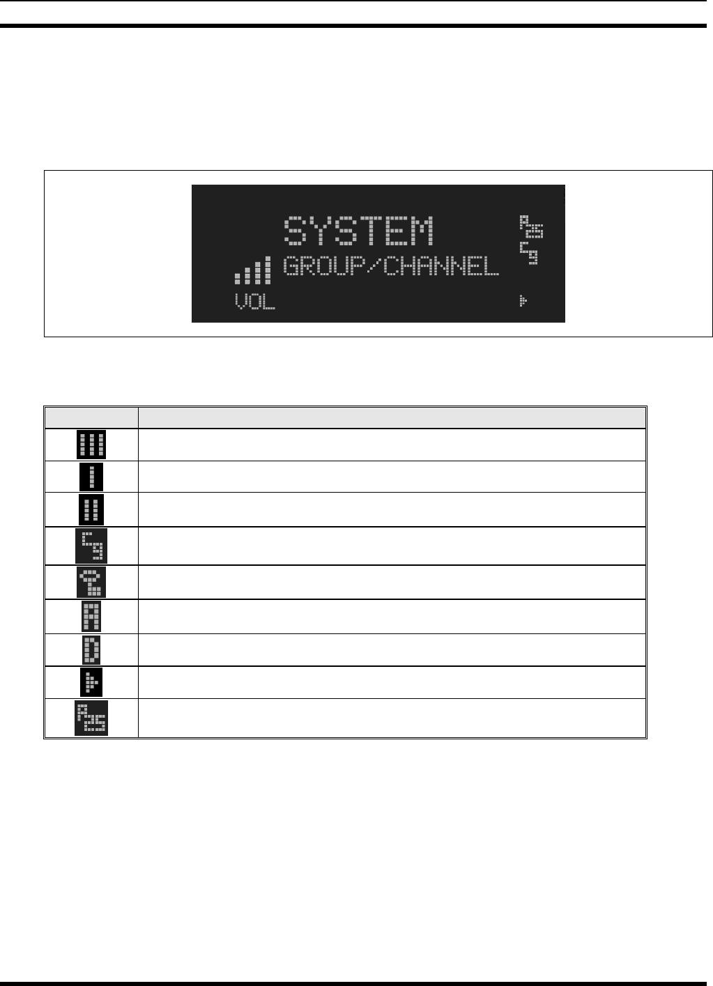
MM-014716-001
85
11 P25 CONVENTIONAL OPERATION
11.1 RADIO STATUS ICONS
Status icons are indicators that show the various operating characteristics of the radio. The icons appear
on the first line of the display.
Figure 11-1: Typical Display
Table 11-1: Icons and Descriptions
ICON DESCRIPTION
Indicates selected group or channel is in scan list.
Indicates selected group or channel is programmed as Priority 1 in scan list.
Indicates selected group or channel is programmed as Priority 2 in scan list.
Indicates a conventional channel enabled with Channel Guard Function.
Transmitting or receiving in encrypted mode.
Indicates the current channel is set up as an analog channel.
Indicates the current channel is set up as a ProVoice channel.
Scan mode enabled.
Indicates the current channel is set up as a Project 25 (P25) channel.

MM-014716-001
86
11.2 MESSAGES
During radio operation, various messages are displayed on either line 1 or line 2. Typical messages
include control channel status information, such as system busy or call denied, or messages associated
with the radio's operation, (i.e. volume adjust). These messages are described as follows:
Table 11-2: Display Messages
MESSAGE NAME DESCRIPTION
TALKARND Talk-around Indicates the radio is operating on conventional channels in talk-around mode (no repeater).
VOL=31 Volume Level Indicates the current volume level. The volume level display ranges from OFF (silent) to 31
(loudest).
UNKNOWN Caller's ID Not
Received Indicates that an individual call is being received, but the caller's ID was not received.
T99 ON Type 99 Decode ON Indicates the Type 99 Decode feature is enabled.
T99 OFF Type 99 Decode OFF Indicates the Type 99 Decode feature is disabled.
PA ON Public Address ON Indicates that the public address function of the radio is enabled.
PA OFF Public Address OFF Momentary (2 seconds) indicates that public address function of the radio was disabled.
ALRM ON External Alarm Enabled Indicates that the external alarm function of the radio is enabled.
ALRM OFF External Alarm
Disabled Momentary (2 seconds) indicates that the external alarm function of the radio was disabled.
PVT DIS Private Mode Disabled Indicates that private mode is disabled or no encryption key has been programmed for the
selected group/channel or special call.
FRCD PVT Forced Private
Operation Indicates that forced private operation has been pre-programmed into radio.
NO KEY # Encryption Key Missing Flashing indicator indicates that no encryption key or an incorrect encryption key is
programmed into the radio.
BCKL=1-6 Backlight Indicates the display intensity and keypad backlight level.
GR Group ID Indicates that the call is a group call and is followed by the GID of the caller.
WHC=1 Who Has Called This display indicates the number from the Who Has Called list. Individual calls received but
not responded to are stored in a Who Has Called list. This list is accessible by pressing the #
key and then the INDV key after the Individual call has timed out or the Clear button is
pressed. This display is on line 2 and the LID of the caller is displayed on the top line.
Currently the list is not implemented and the display will always be WHC=1.
PHONE Phone Call Displayed when a phone call is received from the site. It is displayed in line 1 of the display.
Line 2 of the display will contain the display *INDV* when line 1 contains this message. The
radio interprets a received phone call as an individual call.
MENU Displayed when the menu key is pressed and remains displayed in line 1 until a menu item is
selected.
SYS=1-64 System = 1 - 64 The system number for the current base station of the system displayed in line 1. It is displayed
in line 2 of the display. Press the system key to obtain this display.
INDV=1-99 Individual = 1 - 99 Indicates which item in the individual call list is being displayed. It is displayed in line 2 of the
display. The name or ID of the item in the list is displayed in line 1 of the display.
PHN=1-99 Phone = 1 - 99 Indicates which item in the phone list is being displayed. It is displayed in line 2 of the display.
Line 1 of the display will be the last 3 characters of the list item contents.
SEL PHN Select Phone After pressing the PHN key, selecting an entry from the phone list by typing the entry number
will display this message on Line 1.
Ggg-v.vv Code Group and
Revision Number This is code group and revision number that is displayed in line 2 when the menu item
“REVISION” is selected. The ‘gg’ is the group number of the software. The first ‘v’ is the
hardware version and ‘vv’ is the revision of the software.
*PHONE* Phone Call Displayed when an initiated phone call is in progress. This is displayed on line 2 of the display.
NO ENTRY Indicates that there is no data stored in one of the programmable items in either the phone list
or individual call list. The user programmable items are items 1 through 10 in each list.
INV SYS Invalid System Displayed when the current system is an invalid type.

MM-014716-001
87
MESSAGE NAME DESCRIPTION
CHN=1-99 Channel = 1 - 99 Displayed on line 1 of the display. This is a conventional channel index displayed when the
group key is pressed.
FIX LIST Fixed List The Priority scan list is fixed and cannot be changed using the add or delete keys.
FIXED P1 Fixed Priority 1 The Priority 1 scan channel is fixed and cannot be changed using the add or delete keys.
(c) 2004 Displayed in line 2 when the message ‘M/A-COM’ is displayed in line 1 while displaying
different items under the menu when “REVISION” is selected by the operator.
EM Emergency Indicates an emergency has been declared by the LID that follows the display, “EM.” An
example of this is “EM 01201.”
*INDV* Individual Call Displayed in line 2 of the display when an individual call is in progress (trunked and T99
modes only).
*GROUP* Group Call Indicates a group call is in progress and is displayed on line 1 of the display (trunked and T99
modes only).
SPKR ON External Speaker ON Displayed when the external speaker is enabled.
SPKR OFF External Speaker OFF Displayed when the external speaker is disabled.
BANK=1-8 The bank of keys that are going to be loaded when the keyloader loads encryption keys. This is
only valid for radios that support VGS, VGE, or DES encryption. It is displayed on line 2 of
the display when the encryption keyloader is connected.
KEY LOAD Displayed on line 1 of the display when the encryption keyloader is connected.
KEY ZERO Displayed on line 2 of the display when the reset and option buttons are pressed
simultaneously for approximately two seconds. The encryption keys are zeroed.
SYS KEY System Key Displayed on line 1 of the display in the display key mode of the menu. It is followed in the
second line with a key number “KEY = <1..7>”.
KEY=1-7 Displayed on line 2 of the display in the display key mode of the menu for conventional
systems when the “SYS KEY” or “CHN KEY” is displayed in line 1 and for trunked systems
when the “SYS KEY” or “GRP KEY” is displayed in line 1.
PRIMARY Displayed on line 1 of the display when the primary keys are enabled.
PRS NAME Personality Name Displayed on line 1 of the display under the revision selection of the menu. The personality
name is displayed on line 2 at the same time.
M/A-COM Displayed on line 1 of the display under the revision selection of the menu. The copyright year
is shown in line 2 of display at the same time “(c) 2007.”
11.3 ALERT TONES
The M7300 series mobile radio also provides audible alert tones or “beeps” to indicate the various
operating conditions. These alert tones can be enabled or disabled through programming.
Table 11-3: M7300 EDACS Mode Alert Tones
NAME TONE DESCRIPTION
Call Originate A short mid-pitched tone. Sounds after keying the radio (Push-To-Talk button is
pressed). Indicates the radio has been assigned a
working channel
Carrier Control Timer Five short high-pitched
warning tones followed by a
long low-pitched tone.
Sounds if the programmed time for continuous
transmission is exceeded. The transmitter will shut down
shortly after the alert, interrupting communications.
Release and re-key the PTT button to maintain
communications. This will reset the carrier control timer
and turn the transmitter back on.
Key Press Alert A short tone. Indicates a key has been pressed. A short low-pitched
tone indicates no action was taken because the key is
not active in the current mode.
MM-014716-001
88
11.4 MENU
The menu function accesses features that are not available directly from the keypad. The order and
specific number of menu items available is configurable through programming. Upon radio power up, the
menu item at the beginning of the menu list will always be displayed first. Subsequent access to the menu
function will return the last menu item that was shown in the display. To enter the menu mode, press
MENU. The ramp control, MENU, and CLR are used during the selection process. All of the
selection mode rules previously detailed apply to the menu item selection process with the exception of
direct access. The radio will continue to receive and transmit normally while in the menu function.
A new item is displayed by using the ramp control to scroll through the list in increasing and
decreasing order. The displayed menu item is made active by pressing MENU.
After entering the menu selection mode, the following generic display format will appear.
M E N U
Y Y Y Y Y Y Y Y
Line 1 indicates the radio is in the menu selection mode. Line 2 indicates the menu item (YYYYYYYY)
that is to be viewed or changed (some menu items provide radio information and do not have changeable
parameters).
An example of the menu item selection process and menu item parameter change is detailed below for the
contrast menu item.
1. Press MENU to enter the menu mode.
2. Press the ramp control until the display shows:
M E N U
CONTRAST
3. Press MENU. The contrast menu item is activated and the display will be similar to the following:
CNTRST = X
Y Y Y Y Y Y Y Y
Line 1 shows the active menu item and its current parameter setting (XXX). Line 2 shows the
currently selected system or group name (YYYYYYYY).
4. The menu item's parameter setting shown in the display can now be changed by using the
ramp control to scroll through the list of parameter values. Once the desired setting is reached, press
MENU to store the value and return to the normal display. For menu items that display radio
information, use to scroll through a list of informational displays. The menu items are listed in
Table 9-4.
Table 11-4: Menu Item Information
FEATURE DISPLAY PARAMETER
SETTINGS COMMENT
Contrast Adjust
Menu Item:
CONTRAST
Once selected:
CNTRST=
1, 2, 3, 4, 5, 6, 7, 8 Selects the Contrast level.

MM-014716-001
89
FEATURE DISPLAY PARAMETER
SETTINGS COMMENT
Radio Revision
Information Menu item:
REVISION
Informational displays only
(see radio); no user
selectable settings. Selects the information display to view.
Phone Call
Menu item:
PHN CALL
Once selected: See
Telephone Interconnect
Call Section
Allows access to the Phone Call Feature.
External Alarm Menu Item: EXTALARM
Once Selected:
EXTALARM ON, OFF EXTALARM replaces the system name on the
display as long as the external alarm feature is
enabled.
Public Address
Menu item:
PUB ADDR
Once selected:
PA ON or
PA OFF
ON, OFF Public Address is toggled ON and OFF.
External Speaker
Menu item:
EXT SPKR
Once selected:
SPKR ON or
SPKR OFF
ON, OFF External Speaker is toggled ON and OFF.
Encryption Key
Loading
Menu item: KEYLOAD
Once selected:
KEY LOAD BANK = N Up to 8 banks of 7 keys Enables the radio to accept the loading of encryption
keys.
Display Current
Encryption
Key(s)
Menu item: DISP KEY
Once selected:
SYS KEY, GRP KEY or
CHN KEY and KEY = N
Displays current encryption key number.
Scan Menu item: SCAN ON, OFF Toggles scan function ON or OFF.
Private Mode Menu Item: PRIVATE
Once selected: PVT or key
light. ON, OFF Toggles private function ON or OFF.
Front Panel
Squelch Adjust
Menu Item: SQUELCH
Once selected:
SQLCH=xx 1-16 Allows setting of squelch.
Scan Add Menu item: SCAN ADD
Once selected: Proper scan
icon displayed. S, 2 or 1 Adds group or channel to scan list.
Scan Delete Menu item: SCAN DEL
Once selected: Scan icon
goes out. Deletes channel from scan list.
Scan Add/Delete Menu item: SCAN A/D
When selected: Toggles
through scan selections
Toggle sequence
S, 2, 1, S, ... Changes present group or channel to next scan
choice in scan list.
Last Scanned
Channel Recall
Menu Item: SCAN ADD
Press twice when actively
receiving; three times when
not receiving. Scan icon
displayed.
Changes the selected channel to the last scanned
channel.
Home channel
selection
Menu item: HOME
Once selected: Home group
or channel displayed. Changes to the group or channel defined for Home
function.
System select Menu item: SYS SEL
Once selected: SYS = n 1-64 = (n)umber of desired
system Displays the system selected.
External alarm #2 Menu item: EXTALRM2 ON, OFF Toggles external alarm #2 feature ON or OFF.
System and
Channel selection
Menu item: SYSGRP 1
Menu item: SYSGRP 2
Menu item: SYSGRP 3
Menu item: SYSGRP 4
Menu item: SYSGRP 5
Changes to the System & Channel programmed for
SYSGRP 1-5.
MM-014716-001
90
FEATURE DISPLAY PARAMETER
SETTINGS COMMENT
Mute Menu item: MUTE ON, OFF Toggles the mute function ON or OFF to control the
audio output from the selected radio.
Mute #1 Menu item: MUTE 1 ON, OFF Toggles the mute 1 function ON or OFF on radio
#1.
Mute #2 Menu item: MUTE 2 ON, OFF Toggles the mute 2 function ON or OFF on radio
#2.
Multiple radio
operation Menu item: RADIO ON, OFF Toggles the currently selected radio.
Menu item: RADIO 1 ON, OFF Changes to radio #1.
Radio selection Menu item: RADIO 2 ON, OFF Changes to radio #2.
Talkaround
feature
Menu item: TALKARND
Once selected:
TALKARND on line 1 ON, OFF Toggles talkaround ON or OFF (transmit frequency
changed to receive frequency).
Feature
Encryption
Display
Menu Item: FEATURES
Once selected:
See Feature Encryption
Display section
Informational displays only;
no user selectable settings
Indicates current features program- med into the
radio as well as certain information required to add
features to the radio (refer to the Table of Contents
for Feature Encryption Display.
System Scan
Enable
Menu Item: SYS SCAN
Once selected: SYSC ON
or SYSC OFF ON, OFF System Scan features like ProScan are toggled ON
and OFF.
Type 99 Decode
Enable
Menu Item: T99 ENAB
Once selected:
T99 ON or T99 OFF ON, OFF Type 99 Decode is toggled ON and OFF.
11.5 GROUP CALLS IN P25 MODE
11.5.1 Transmitting a Group Call
1. Select the desired P25 system.
2. Select the Talk Group/Conventional Channel. (Selected simultaneously using either the
system/group/channel knob or the group key.)
3. Press and hold the PTT.
4. When a grant tone is received (if enabled through programming), speak into the microphone.
5. Release PTT and wait for response.
11.5.2 Receiving a Group Call
The radio will unmute according to the squelch mode defined in the radio personality (monitor, normal,
selective).
1. Select the desired P25 system and Talk Group/Channel or turn scan on and make sure the desired
channel is in the scan list.
2. When the radio receives a P25 call, the radio will unmute and the channel name will appear in the
display.
3. Press the PTT button to respond.
MM-014716-001
91
11.6 INDIVIDUAL CALLS IN P25 MODE
11.6.1 Transmitting an Individual Call
1. Select the desired P25 system.
2. Select the radio unit to call (callee source ID) from the pre-programmed individual call list or enter
the ID number on the radio keypad.
3. Press and hold the PTT.
4. When grant tone is received (if enabled through programming) speak into the microphone.
5. Release the PTT.
11.6.2 Receiving an Individual Call
The radio will unmute according to the squelch mode defined in the radio personality (monitor, normal,
selective).
1. Select the desired P25 system and Talk Group/Channel or turn scan on and make sure the desired
channel is in the scan list.
2. When the radio receives a P25 call, the radio will unmute and the ID of the transmitting radio will
appear in the display.
3. Press the PTT button to respond.
Unanswered calls will appear in the Who Has Called (WHC) list.
11.7 EMERGENCY GROUP CALLS IN P25 MODE
There is no method available for a system-wide Emergency clear. An emergency group call
must be cleared on each individual radio.
11.7.1 Declaring an Emergency Group Call
1. Select the desired P25 system and Talk Group/Channel.
2. Press the red emergency button on the top of the radio. The radio will broadcast a short emergency
transmission with the emergency bit set. “TXEMER” will appear in the display of the transmitting
radio.
3. To send a voice message, press the PTT and speak into the microphone.
4. To clear an emergency from the transmitting radio, perform one of the following steps:
a. Change systems.
b. Change channels (if not prohibited by programming).
c. Cycle power by turning radio off and then back on.
d. Press the Clear and Emergency buttons simultaneously, providing the Clear Emergency option is
enabled in the Supervisory Options in the personality.

MM-014716-001
92
11.7.2 Receiving an Emergency Group Call
1. Select the desired P25 System and Talk Group/Channel.
2. When the radio detects an incoming Emergency Group Call, the radio will sound an alert tone and
“RXEMER” will appear in the display.
3. Voice or emergency transmissions will be heard at the receiving radio.
4. To clear an emergency from the receiving radio, perform one of the following steps:
a. Change systems.
b. Change channels (if not prohibited by programming).
c. Cycle power by turning radio off and then back on.
d. Press the Clear and Emergency buttons simultaneously, providing the Clear Emergency option is
enabled in the Supervisory Options in the personality.

MM-014716-001
93
12 BASIC TROUBLESHOOTING
If the radio is not operating properly, check Table 12-1 for likely causes. For additional assistance,
contact a qualified service technician.
Table 12-1: Basic Troubleshooting
SYMPTOM CAUSE SOLUTION
Radio will not turn on. No power. Test the connection to the vehicle power
supply.
Radio will not turn off. If in multiple control head
configuration, one of the attached
control heads is still powered up. Power off all control heads.
Radio will not register
or does not receive
provisioning data. Bad logon credentials. Check logon and password.
No audio. Speaker volume is muted. Increase the volume level.
Poor audio. Transmitting or receiving in a
poor coverage area or subject to
interference.
Check network connectivity and move to a
better coverage area if possible. Report the
area without coverage to an authorized
network technician.
Poor display visibility. Ambient Light Sensor is
obstructed. Clear the obstruction and give the sensor a
clear path to ambient light.
No network
connectivity icon in
display.
Radio is out-of-range or cannot
connect with the OpenSky
network.
Base station network connection
has failed.
Return to coverage area if possible and
wait for condition to clear.
Use single-site trunking or switch to an
alternate channel.
Radio will not
transmit. Radio may be out of coverage
area or may be overheated.
Return to coverage area if possible. If
overheated, let radio cool before retrying
transmission. Report this failure to an
authorized technician.
“Warning: No MRU”
Message.
Radio control head is unable to
communicate with mobile radio
unit (radio transceiver).
Have the radio connections checked by an
authorized technician.
Control head
randomly changes
display.
In multiple control head
configurations, another user is
operating the radio from another
control head.
None
Encrypted calls cannot
be made. Not authorized to use. Contact system administrator to request
encryption privileges.
Screen displays:
UNAUTH3
The radio network ID has not
been added to the network. Contact system administrator.
Screen displays:
NOAUTHV
Radio authentication of the
VNIC failed. Contact system administrator.

MM-014716-001
94
SYMPTOM CAUSE SOLUTION
Screen displays:
NOAUTHM
VNIC authentication of the radio
failed. Contact system administrator.
Screen displays:
NOSUPRT
The voice authentication security
policy is set to only allow
authenticated users. Contact system administrator.
Encrypted calls cannot
be made. User not logged in. Log in (refer to Section 7.14.1).

MM-014716-001
95
13 TECHNICAL ASSISTANCE
The Technical Assistance Center's (TAC) resources are available to help with overall system operation,
maintenance, upgrades and product support. TAC is the point of contact when answers are needed to
technical questions.
Product specialists, with detailed knowledge of product operation, maintenance and repair provide
technical support via a toll-free (in North American) telephone number. Support is also available through
mail, fax and e-mail.
For more information about technical assistance services, contact your sales representative, or call the
Technical Assistance Center at:
North America: 1-800-528-7711
International: 1-434-385-2400
Fax: 1-434-455-6712
E-mail: tac@tycoelectronics.com

MM-014716-001
96
14 KEYPAD REMAPPING
If the keys have been remapped to provide new functions, fill in the following template for future reference.
Button Function Button Function
Emergency 1
Preset A 2
Preset B 3
Preset C 4
Rocker • 5
Rocker •• 6
Rocker + 7
Rocker - 8
MENU 9
OPT/OPTION *
CLR/CLEAR 0
SCAN #

MM-014716-001
97
15 RADIO SETUP
RADIO TYPE:
FREQUENCY BAND:
OPERATOR'S NAME:
EMERGENCY GROUP:
SYSTEM NUMBER SYSTEM NAME TRK/CNV GRP/CHN NUMBER GRP/CHN NAME USE

MM-014716-001
98
SYSTEM NUMBER SYSTEM NAME TRK/CNV GRP/CHN NUMBER GRP/CHN NAME USE

MM-014716-001
99
SYSTEM NUMBER SYSTEM NAME TRK/CNV GRP/CHN NUMBER GRP/CHN NAME USE

MM-014716-001
100
SYSTEM NUMBER SYSTEM NAME TRK/CNV GRP/CHN NUMBER GRP/CHN NAME USE

MM-014716-001
101
16 WARRANTY
A. M/A-COM, Inc. (hereinafter "Seller") warrants to the original purchaser for use (hereinafter "Buyer") that Equipment manufactured
by or for the Seller shall be free from defects in material and workmanship, and shall conform to its published specifications. With
respect to all non-M/A-COM Equipment, Seller gives no warranty, and only the warranty, if any, given by the manufacturer shall
apply. Rechargeable batteries are excluded from this warranty but are warranted under a separate Rechargeable Battery
Warranty (ECR-7048).
B. Seller’s obligations set forth in Paragraph C below shall apply only to failures to meet the above warranties occurring within the
following periods of time from date of sale to the Buyer and are conditioned on Buyer’s giving written notice to Seller within thirty
(30) days of such occurrence:
1. for fuses and non-rechargeable batteries, operable on arrival only.
2. for parts and accessories (except as noted in B.1) sold by Seller’s Service Parts Operation, ninety (90) days.
3. for P7200, P7100IP, P5400, P5300, P5200, P5100, P3300, PANTHER™ 405P and 605P, M7300, M7200 (including V-TAC),
M7100 IP, M5300 and M3300 radios, two (2) years.
4. for all other equipment of Seller’s manufacture, one (1) year.
C. If any Equipment fails to meet the foregoing warranties, Seller shall correct the failure at its option (i) by repairing any defective or
damaged part or parts thereof, (ii) by making available at Seller’s factory any necessary repaired or replacement parts, or (iii) by
replacing the failed Equipment with equivalent new or refurbished Equipment. Any repaired or replacement part furnished
hereunder shall be warranted for the remainder of the warranty period of the Equipment in which it is installed. Where such
failure cannot be corrected by Seller’s reasonable efforts, the parties will negotiate an equitable adjustment in price. Labor to
perform warranty service will be provided at no charge during the warranty period only for the Equipment covered under
Paragraph B.3 and B.4. To be eligible for no-charge labor, service must be performed at a M/A-COM factory, by an Authorized
Service Center (ASC) or other Servicer approved for these purposes either at its place of business during normal business hours,
for mobile or personal equipment, or at the Buyer’s location, for fixed location equipment. Service on fixed location equipment
more than thirty (30) miles from the Service Center or other approved Servicer’s place of business will include a charge for
transportation.
D. Seller’s obligations under Paragraph C shall not apply to any Equipment, or part thereof, which (i) has been modified or otherwise
altered other than pursuant to Seller’s written instructions or written approval or, (ii) is normally consumed in operation or, (iii) has
a normal life inherently shorter than the warranty periods specified in Paragraph B, or (iv) is not properly stored, installed, used,
maintained or repaired, or, (v) has been subjected to any other kind of misuse or detrimental exposure, or has been involved in
an accident.
E. The preceding paragraphs set forth the exclusive remedies for claims based upon defects in or nonconformity of the Equipment,
whether the claim is in contract, warranty, tort (including negligence), strict liability or otherwise, and however instituted. Upon the
expiration of the warranty period, all such liability shall terminate. The foregoing warranties are exclusive and in lieu of all other
warranties, whether oral, written, expressed, implied or statutory. NO IMPLIED OR STATUTORY WARRANTIES OF
MERCHANTABILITY OR FITNESS FOR PARTICULAR PURPOSE SHALL APPLY. IN NO EVENT SHALL THE SELLER BE
LIABLE FOR ANY INCIDENTAL, CONSEQUENTIAL, SPECIAL, INDIRECT OR EXEMPLARY DAMAGES.
This warranty applies only within the United States.
M/A-COM, Inc. M/A-COM, Inc.
1011 Pawtucket Blvd. 221 Jefferson Ridge Parkway
Lowell, MA 01853 Lynchburg, VA 24501
1-877-OPENSKY 1-800-528-7711
ECR-7047E

MM-014716-001
102
This page intentionally left blank.

Tyco Electronics Wireless Systems Segment
221 Jefferson Ridge Parkway
Lynchburg, Virginia 24501
(Outside USA, 1-434-385-2400) Toll Free 1-800-528-7711
www.macom-wireless.com Printed in U.S.A.

Installation and Product Safety Manual
MM-014763-001
May/08
M/A-COM
M7300
700 and 800 MHz
Dual-Band Half-Duplex
Front and Remote-Mount Mobile Radios
with CH-721 Scan and System
Control Heads

MM-014763-001
2
MANUAL REVISION HISTORY
REV. DATE REASON FOR CHANGE
- May/08 PRELIMINARY manual (5/27/2008).
M/A-COM Technical Publications would particularly appreciate feedback on any errors found in this document and
suggestions on how the document could be improved. Submit your comments and suggestions to:
Tyco Electronics Wireless Systems Segment
M/A-COM, Inc. or fax your comments to: 1-434-455-6851
Technical Publications
221 Jefferson Ridge Parkway or e-mail us at: techpubs@tycoelectronics.com
Lynchburg, VA 24501
CREDITS
OpenSky and EDACS are registered trademarks of M/A-COM, Inc.
ProVoice is a trademark of M/A-COM, Inc.
AMBE and IMBE are registered trademarks of Digital Voice Systems, Inc.
Bird is a registered trademark of Bird Electronic Corporation.
Microsoft and Windows are registered trademarks of Microsoft Corporation.
SmartSiren is a registered trademark of Federal Signal Corporation.
All other brand and product names are trademarks, registered trademarks, or service marks of their respective holders.
NOTICE
This device is made under license under one or more of the following U.S. Patents: 4,590,473; 4,636,791; 5,148,482;
5,185,796; 5,271,017; 5,377,229; 4,716,407; 4,972,460; 5,502,767; 5,146,497; 5,164,986; 5,185,795.
The voice coding technology embodied in this product is protected by intellectual property rights including patent rights,
copyrights, and trade secrets of Digital Voice Systems, Inc. The user of this technology is explicitly prohibited from
attempting to decompile, reverse engineer, or disassemble the Object Code, or in any other way convert the Object Code into
human-readable form.
This manual covers M/A-COM products manufactured and sold by M/A-COM, Inc.
Repairs to this equipment should be made only by an authorized service technician or facility designated by the supplier. Any
repairs, alterations or substitution of recommended parts made by the user to this equipment not approved by the
manufacturer could void the user’s authority to operate the equipment in addition to the manufacturer’s warranty.
The software contained in this device is copyrighted by M/A-COM, Inc. Unpublished rights are reserved under the copyright
laws of the United States.
This product conforms to the European Union WEEE Directive 2002/96/EC. Do not dispose of this product in a
public landfill. Take it to a recycling center at the end of its life.
This manual is published by M/A-COM, Inc. without any warranty. Improvements and changes to this manual necessitated by typographical errors,
inaccuracies of current information, or improvements to programs and/or equipment, may be made by M/A-COM, Inc., at any time and without notice. Such
changes will be incorporated into new editions of this manual. No part of this manual may be reproduced or transmitted in any form or by any means,
electronic or mechanical, including photocopying and recording, for any purpose, without the express written permission of M/A-COM, Inc.
Copyright© 2008, M/A-COM, Inc. All rights reserved.

MM-014763-001
3
TABLE OF CONTENTS Page
1 REGULATORY AND SAFETY INFORMATION....................................................................................6
1.1 SAFETY SYMBOL CONVENTIONS.................................................................................................6
1.2 RF ENERGY EXPOSURE AWARENESS AND CONTROL INFORMATION FOR FCC
OCCUPATIONAL USE REQUIREMENTS........................................................................................ 6
1.2.1 Federal Communications Commission Regulations...............................................................7
1.3 COMPLIANCE WITH RF EXPOSURE STANDARDS...................................................................... 7
1.3.1 Mobile Antennas ....................................................................................................................8
1.3.2 Approved Accessories............................................................................................................8
1.3.3 Contact Information................................................................................................................9
1.4 OCCUPATIONAL SAFETY GUIDELINES AND SAFETY TRAINING INFORMATION .............9
1.5 COMMON HAZARDS ........................................................................................................................9
1.6 SAFE DRIVING RECOMMENDATIONS........................................................................................10
1.7 OPERATING RULES AND REGULATIONS ..................................................................................10
1.8 OPERATING TIPS............................................................................................................................. 11
2 SPECIFICATIONS.....................................................................................................................................12
2.1 GENERAL..........................................................................................................................................12
2.2 TRANSCEIVER.................................................................................................................................12
2.3 REGULATORY .................................................................................................................................13
3 INTRODUCTION.......................................................................................................................................14
3.1 GENERAL DESCRIPTION ...............................................................................................................14
3.2 RELATED PUBLICATIONS.............................................................................................................16
3.3 REPLACEMENT PARTS ..................................................................................................................16
3.4 CONTACTING M/A-COM FOR TECHNICAL ASSISTANCE .......................................................16
4 UNPACKING AND CHECKING THE EQUIPMENT...........................................................................17
4.1 MATERIALS .....................................................................................................................................17
4.2 MATERIAL INSPECTION................................................................................................................ 20
5 PLANNING THE INSTALLATION.........................................................................................................21
5.1 GENERAL INFORMATION .............................................................................................................21
5.2 TOOLS REQUIRED...........................................................................................................................21
5.3 LOCATING COMPONENTS ............................................................................................................24
6 ANTENNA INSTALLATION....................................................................................................................25
6.1 ANTENNA MOUNTING LOCATIONS ...........................................................................................25
6.1.1 Direct Center or Center-Rear of Rooftop .............................................................................26
6.1.2 Center of Trunk Lid..............................................................................................................26
6.2 ANTENNA INSTALLATION PROCEDURE...................................................................................26
6.2.1 Install the Mobile Antenna ...................................................................................................26
6.2.2 Install the GPS Antenna (Required Only if Radio has GPS Receiver Option).................... 27
7 FRONT-MOUNT RADIO INSTALLATION...........................................................................................29
7.1 MOUNTING THE FRONT-MOUNT RADIO ................................................................................... 29
7.1.1 Mounting Bracket Installation ..............................................................................................30
7.1.2 Inserting the Radio into the Mounting Bracket ....................................................................32
7.2 FRONT-MOUNT RADIO’S DC POWER INSTALLATION............................................................32
7.2.1 Overview of On/Off Power Wiring Configurations ............................................................. 32
7.2.2 DC Power Cable and Main Fuse Holder Installation............................................................33
8 REMOTE-MOUNT RADIO INSTALLATION.......................................................................................36
8.1 MOUNTING THE REMOTE-MOUNT RADIO................................................................................36

MM-014763-001
4
TABLE OF CONTENTS Page
8.1.1 Mounting Bracket Installation ..............................................................................................36
8.1.2 Inserting the Radio into the Mounting Bracket.....................................................................40
8.2 REMOTE-MOUNT RADIO’S DC POWER INSTALLATION.........................................................40
8.2.1 Overview of On/Off Power Wiring Configurations..............................................................40
8.2.2 DC Power Cable and Main Fuse Holder Installation............................................................41
8.3 CONTROL HEAD INSTALLATION ................................................................................................43
8.3.1 General Information..............................................................................................................43
8.3.2 Control Head Mechanical Installation ..................................................................................46
8.3.3 Control Head-to-Radio CAN Cable Connections.................................................................47
8.3.4 Control Head Power Cable Installation ................................................................................49
9 SPEAKER INSTALLATION.....................................................................................................................53
9.1 FRONT-MOUNT RADIO INSTALLATION.....................................................................................53
9.2 REMOTE-MOUNT RADIO INSTALLATION .................................................................................53
10 MICROPHONE ATTACHMENT.............................................................................................................54
11 OPTIONAL CABLES.................................................................................................................................55
11.1 M5300/M7300 OPTION CABLE CA-012349-001 ............................................................................55
11.2 SERIAL PROGRAMMING CABLE CA-013671 ..............................................................................58
11.3 CH-721 OPTION CABLE CA-011854-001........................................................................................59
11.4 CH-721 SERIAL PROGRAMMING CABLE CA-104861.................................................................60
12 GPS NMEA-FORMATTED SERIAL DATA CONNECTION...............................................................61
13 INITIAL POWER-UP TEST......................................................................................................................62
14 PERFORMANCE TESTS...........................................................................................................................63
14.1 CHANGING OPERATING MODE FOR TESTS...............................................................................63
14.1.1 Changing from OpenSky to Conventional............................................................................63
14.1.2 Changing from Conventional to OpenSky............................................................................64
14.2 REQUIRED TEST EQUIPMENT ......................................................................................................64
14.3 TRANSMITTING INTO A DUMMY LOAD.....................................................................................65
14.4 TRANSMITTING INTO THE MOBILE ANTENNA........................................................................66
14.5 TEST PERFORMANCE DATA FORM.............................................................................................69
15 COMPLETE THE INSTALLATION........................................................................................................70
16 WARRANTY ...............................................................................................................................................71
(Continued)

MM-014763-001
5
FIGURES
Page
Figure 5-1: Typical Front-Mount Mobile Radio Installation in a Standard Passenger Vehicle ..........................22
Figure 5-2: Typical Remote-Mount Mobile Radio Installation in a Standard Passenger Vehicle....................... 22
Figure 5-3: M7300 Front-Mount and Remote-Mount Mobile Radios — Front and Rear Views........................ 23
Figure 6-1: Recommended Antenna Mounting Locations with Antenna Part Numbers.....................................25
Figure 6-2: Crimping Instructions for TNC RF Connector .................................................................................27
Figure 7-1: Front-Mount Mounting Bracket Kit KT101533V1 ..........................................................................30
Figure 7-2: Mounting Bracket FM101319V1 (Marked KTB0310) Dimensions [for Front-Mount M7300
Mobile Radio (Radio Not Shown)].............................................................................................. 31
Figure 8-1: Remote-Mount Radio Dimensions ...................................................................................................37
Figure 8-2: Remote-Mount Mounting Bracket Kit KT23117 .............................................................................38
Figure 8-3: Mounting Bracket FM103111V1 Dimensions [for Remote-Mount M7300 Mobile Radio
(Radio Not Shown)].....................................................................................................................39
Figure 8-4: CH-721 Scan Model Control Head Front Panel ...............................................................................44
Figure 8-5: CH-721 System Model Control Head Front Panel ...........................................................................44
Figure 8-6: CH-721 Rear Panel (both control head models)............................................................................... 45
Figure 8-7: Standard U-Shaped Control Head Mounting Bracket (Kit Part Number KT-008608)..................... 46
Figure 8-8: Optional Control Head Mounting Pedestal (Part Number MACDOS0012).....................................46
Figure 8-9: CAN Link Connections for a Single Control Head Installation .......................................................48
Figure 8-10: Typical CAN Link Connections for a Multi-Control Head Installation .........................................48
Figure 10-1: Attaching the Microphone to the CH-721Control Head................................................................. 54
Figure 11-1: M5300/M7300 Option Cable CA-012349-001...............................................................................55
Figure 11-2: Programming Cables CA-013671-010 and -020 ............................................................................58
Figure 11-3: CH-721 Option Cable CA-011854-001..........................................................................................59
Figure 11-4: Programming Cable CA-104861 ....................................................................................................60
Figure 14-1: Wattmeter Connections for Antenna System Tests ........................................................................65
TABLES
Page
Table 1-1: Recommended Minimum Safe Lateral Distance from Transmitting Antenna......................................8
Table 4-1: Installation Kit MAMW-NZN6W for Front-Mount M7300 Mobile Radio.......................................17
Table 4-2: Installation Kit MAMW-NZN7R for Remote-Mount M7300 Mobile Radio with CH-721
Control Head................................................................................................................................18
Table 4-3: Additional Options and Accessories for M7300 Mobile Radios ....................................................... 18
Table 4-4: Additional Options and Accessories for CH-721 Control Heads.......................................................20
Table 11-1: M5300/M7300 Option Cable CA-012349-001 Interconnections.....................................................56
Table 14-1: Required Test Equipment ................................................................................................................64
MM-014763-001
6
1 REGULATORY AND SAFETY INFORMATION
1.1 SAFETY SYMBOL CONVENTIONS
The following conventions are used in this manual to alert the user to general safety precautions that must
be observed during all phases of operation, installation, service, and repair of this product. Failure to
comply with these precautions or with specific warnings elsewhere violates safety standards of design,
manufacture, and intended use of the product. M/A-COM, Inc. assumes no liability for the customer's
failure to comply with these standards.
The WARNING symbol calls attention to a procedure, practice, or the like, which,
if not correctly performed or adhered to, could result in personal injury. Do not
proceed beyond a WARNING symbol until the conditions identified are fully
understood or met.
CAUTION
The CAUTION symbol calls attention to an operating procedure, practice, or the like,
which, if not performed correctly or adhered to, could result in damage to the
equipment or severely degrade equipment performance.
The NOTE symbol calls attention to supplemental information, which may improve
system performance or clarify a process or procedure.
1.2 RF ENERGY EXPOSURE AWARENESS AND CONTROL
INFORMATION FOR FCC OCCUPATIONAL USE REQUIREMENTS
Before using the two-way mobile radio, read this important RF energy awareness and control
information and operational instructions to ensure compliance with RF exposure guidelines.
This radio is intended for use in occupational/controlled conditions, where users
have full knowledge of their exposure and can exercise control over their
exposure to remain below RF exposure limits. This radio is NOT authorized for
general population, consumer, or any other use.
CAUTION
Changes or modifications not expressly approved by M/A-COM, Inc. could void the
user's authority to operate the equipment.
This two-way radio uses electromagnetic energy in the radio frequency (RF) spectrum to provide
communications between two or more users over a distance. It uses RF energy or radio waves to send and
receive calls. RF energy is one form of electromagnetic energy. Other forms include, but are not limited
to, electric power, sunlight, and x-rays. RF energy, however, should not be confused with these other
forms of electromagnetic energy, which, when used improperly, can cause biological damage. Very high
levels of x-rays, for example, can damage tissues and genetic material.
Experts in science, engineering, medicine, health, and industry work with organizations to develop
standards for exposure to RF energy. These standards provide recommended levels of RF exposure for

MM-014763-001
7
both workers and the general public. These recommended RF exposure levels include substantial margins
of protection. All two-way radios marketed in North America are designed, manufactured, and tested to
ensure they meet government-established RF exposure levels. In addition, manufacturers also recommend
specific operating instructions to users of two-way radios. These instructions are important because they
inform users about RF energy exposure and provide simple procedures on how to control it. Refer to the
following websites for more information on what RF energy exposure is and how to control exposure to
assure compliance with established RF exposure limits:
http://www.fcc.gov/oet/rfsafety/rf-faqs.html
http://www.osha.gov./SLTC/radiofrequencyradiation/index.html
1.2.1 Federal Communications Commission Regulations
Before it was marketed in the United States, the M7300 two-way mobile radio was tested to ensure
compliance with FCC RF energy exposure limits for mobile two-way radios. When two-way radios are
used as a consequence of employment, the FCC requires users to be fully aware of and able to control
their exposure to meet occupational requirements. Exposure awareness can be facilitated by the use of a
label directing users to specific user awareness information. The radio has an RF exposure product label.
Also, this Installation and Product Safety Manual and the applicable Operator’s Manual include
information and operating instructions required to control RF exposure and to satisfy compliance
requirements.
1.3 COMPLIANCE WITH RF EXPOSURE STANDARDS
The M7300 two-way mobile radio is designed and tested to comply with a number of national and
international standards and guidelines regarding human exposure to RF electromagnetic energy. This
radio complies with the IEEE and ICNIRP exposure limits for occupational/controlled RF exposure
environment at duty-cycle times of up to 50% (50% transmit, 50% receive), and it is authorized by the
FCC for occupational use. In terms of measuring RF energy for compliance with the FCC exposure
guidelines, the radio’s antenna radiates measurable RF energy only while it is transmitting (talking), not
when it is receiving (listening), or in a standby mode.
The M7300 mobile two-way radio complies with the following RF energy exposure standards and
guidelines:
• United States Federal Communications Commission (FCC), Code of Federal Regulations; 47 CFR
§ 2 sub-part J.
• American National Standards Institute (ANSI)/Institute of Electrical and Electronic Engineers (IEEE)
C95.1-2005.
• Institute of Electrical and Electronic Engineers (IEEE) C95.1-2005.
• IC Standard RSS-102, Issue 2, 2005: “Spectrum Management and Telecommunications Radio
Standards Specification. Radiofrequency Exposure Compliance of Radiocommunication Apparatus
(All Frequency Bands).
CAUTION
Table 1-1 lists the recommended minimum safe lateral distances for a controlled
environment and for unaware bystanders in an uncontrolled environment, from
transmitting antennas (i.e., monopoles over a ground plane, or dipoles) at rated radio
power for mobile radios installed in a vehicle. Transmit only when unaware bystanders
are at least the uncontrolled recommended minimum safe lateral distance away from
the transmitting antenna. Based on the highest radiated RF power and with respect to
the cables supplied with the antennas, the distances listed in Table 1-1 are considered
as safe distances for controlled and uncontrolled environments for the listed antennas.

MM-014763-001
8
Based on the highest radiated RF power and the highest antenna gain in antennas to be used with M7300,
the following distances are considered as safe distances for controlled and uncontrolled environments
with the M7300 mobile radio transmitting at a maximum 50% duty cycle:
Table 1-1: Recommended Minimum Safe Lateral Distance from Transmitting Antenna
RECOMMENDED MINIMUM LATERAL HUMAN BODY
DISTANCE FROM TRANSMITTING ANTENNA
ANTENNA
PART NUMBER
(Catalog Number) ANTENNA DESCRIPTION CONTROLLED
ENVIRONMENT
(Centimeters)
UNCONTROLLED
ENVIRONMENT
(Centimeters)
AN-025167-001
(Cat. No. MAMW-AN3J) 700/800 MHz Standard
Rooftop-Mount; 3 dBd Gain 28 69
AN-025167-002
(Cat. No. MAMW-AN3K) 700/800 MHz Elevated-Feed
Rooftop-Mount; 3 dBd Gain 28 69
AN-025167-004
(Cat. No. MAMW-AN3V) 700/800 MHz GPS Combo
Rooftop-Mount; 3 dBd Gain 28 69
AN-025167-005
(Cat. No. MAMW-NAN3W)
700/800 MHz GPS Combo
Elevated-Feed Rooftop-Mount;
3 dBd Gain 28 69
AN-025167-006
(Cat. No. MAMW-NAN3X) 700/800 MHz Magnetic-Mount;
3 dBd Gain 29 72
AN-025167-010
(Cat. No. MAMW-NAN5B) 700/800 MHz Low-Profile
Rooftop-Mount; 2 dBd Gain 28 69
AN-025167-011
(Cat. No. MAMW-NAN5C)
700/800 MHz GPS Combo
Low-Profile Rooftop-Mount;
2 dBd Gain 28 69
AN-025167-014
(Cat. No. MAMW-NAN5U) 700/800 MHz Standard
Rooftop-Mount; 5 dBd Gain 39 87
AN-025167-015
(Cat. No. MAMW-NAN5V) 700/800 MHz GPS Combo
Rooftop-Mount; 5 dBd Gain 39 87
1.3.1 Mobile Antennas
The antenna(s) for the radio must be installed in accordance with Section 6 in this manual. Refer to Figure
6-1 on page 25 for applicable antenna part numbers. Installation guidelines presented in Section 6 are
limited to metal-body motor vehicles or vehicles with appropriate ground planes.
Use only the M/A-COM approved/supplied antenna(s) or an approved replacement antenna. Unauthorized
antennas, modifications, or attachments can cause the FCC RF exposure limits to be exceeded.
1.3.2 Approved Accessories
The radio has been tested and meets FCC RF guidelines when used with M/A-COM accessories supplied
or designated for use with it. Use of other accessories may not ensure compliance with the FCC’s RF
exposure guidelines, and may violate FCC regulations. For a list of approved accessories refer to Section
4 in this manual (begins on page 17) and/or M/A-COM’s Products and Services Catalog.

MM-014763-001
9
1.3.3 Contact Information
For additional information on RF exposure and other information, contact M/A-COM using one of the
contact links listed in Section 3.4 on page 16.
1.4 OCCUPATIONAL SAFETY GUIDELINES AND SAFETY TRAINING
INFORMATION
To ensure bodily exposure to RF electromagnetic energy is within the FCC allowable limits for
occupational use. Always adhere to the following basic guidelines:
1. The push-to-talk button should only be depressed when intending to send a voice message.
2. The radio should only be used for necessary work-related communications.
3. The radio should only be used by authorized and trained personnel. It should never be operated by
children.
4. Do not attempt any unauthorized modification to the radio. Changes or modifications to the radio may
cause harmful interference and/or cause it to exceed FCC RF exposure limits. Only qualified
personnel should service the radio.
5. Always use M/A-COM authorized accessories (antennas, control heads, speakers/mics, etc.). Use of
unauthorized accessories can cause the FCC RF exposure compliance requirements to be exceeded.
The information listed above provides the user with information needed to make him or her aware of a RF
exposure, and what to do to assure that this radio operates within the FCC exposure limits of this radio.
1.5 COMMON HAZARDS
The operator of any mobile radio should be aware of certain hazards common to
the operation of vehicular radio transmissions. Possible hazards include but are
not limited to:
• Explosive Atmospheres — Just as it is dangerous to fuel a vehicle while its motor running, be sure
to turn the radio OFF while fueling the vehicle. If the radio is mounted in the trunk of the vehicle,
DO NOT carry containers of fuel in the trunk.
Areas with potentially explosive atmosphere are often, but not always, clearly marked. Turn the radio
OFF when in any area with a potentially explosive atmosphere. It is rare, but not impossible that the
radio or its accessories could generate sparks.
• Interference To Vehicular Electronic Systems — Electronic fuel injection systems, electronic anti-
skid braking systems, electronic cruise control systems, etc., are typical of the types of electronic
devices that can malfunction due to the lack of protection from radio frequency (RF) energy present
when transmitting. If the vehicle contains such equipment, consult the dealer for the make of vehicle
and enlist his aid in determining if such electronic circuits perform normally when the radio is
transmitting.
• Electric Blasting Caps — To prevent accidental detonation of electric blasting caps, DO NOT use
two-way radios within 1000 feet (305 meters) of blasting operations. Always obey the “Turn Off
Two-Way Radios” (or equivalent) signs posted where electric blasting caps are being used. (OSHA
Standard: 1926.900).

MM-014763-001
10
• Radio Frequency Energy — To prevent burns or related physical injury from radio frequency
energy, do not operate the transmitter when anyone outside of the vehicle is within the minimum safe
distance from the antenna as specified in Table 1-1. Refer to Section 1.2 for additional information.
• Vehicles Powered By Liquefied Petroleum (LP) Gas — Radio installation in vehicles powered by
liquefied petroleum gas, where the LP gas container is located in the trunk or other sealed-off space
within the interior of the vehicle, must conform to the National Fire Protection Association standard
NFPA 58. This requires:
¾ The space containing the radio equipment must be isolated by a seal from the space containing
the LP gas container and its fittings.
¾ Outside filling connections must be used for the LP gas container.
¾ The LP gas container space shall be vented to the outside of the vehicle.
• Vehicles Equipped with Airbags — For driver and passenger safety, avoid mounting the radio’s
control head (or any other component) above or near airbag deployment areas. In addition to driver-
side and passenger-side front-impact airbags, some vehicles may also be equipped with side-impact
airbags. For occupant safety, verify the location of all airbags within the vehicle before installing the
radio equipment.
1.6 SAFE DRIVING RECOMMENDATIONS
The American Automobile Association (AAA) advocates the following key safe driving recommenda-
tions:
• Read the literature on the safe operation of the radio.
• Keep both hands on the steering wheel and the microphone in its hanger whenever the vehicle is in
motion.
• Place calls only when the vehicle is stopped.
• When talking from a moving vehicle is unavoidable, drive in the slower lane. Keep conversations
brief.
• If a conversation requires taking notes or complex thought, stop the vehicle in a safe place and
continue the call.
• Whenever using a mobile radio, exercise caution.
1.7 OPERATING RULES AND REGULATIONS
Two-way FM radio systems must be operated in accordance with the rules and regulations of the local,
regional, or national government.
In the United States, the M7300 mobile radio must be operated in accordance with the rules and
regulations of the Federal Communications Commission (FCC). Operators of two-way radio equipment,
must be thoroughly familiar with the rules that apply to the particular type of radio operation. Following
these rules helps eliminate confusion, assures the most efficient use of the existing radio channels, and
results in a smoothly functioning radio network.
When using a two-way radio, remember these rules:
• It is a violation of FCC rules to interrupt any distress or emergency message. The radio operates in
much the same way as a telephone “party line.” Therefore, always listen to make sure the channel is
clear before transmitting. Emergency calls have priority over all other messages. If someone is
MM-014763-001
11
sending an emergency message – such as reporting a fire or asking for help in an accident, do not
transmit unless assistance can be offered.
• The use of profane or obscene language is prohibited by Federal law.
• It is against the law to send false call letters or false distress or emergency messages. The FCC
requires keeping conversations brief and confine them to business. To save time, use coded messages
whenever possible.
• Using the radio to send personal messages (except in an emergency) is a violation of FCC rules. Send
only essential messages.
• It is against Federal law to repeat or otherwise make known anything overheard on the radio.
Conversations between others sharing the channel must be regarded as confidential.
• The FCC requires self-identification at certain specific times by means of call letters. Refer to the
rules that apply to the particular type of operation for the proper procedure.
• No changes or adjustments shall be made to the equipment except by an authorized or certified
electronics technician.
CAUTION
Under U.S. law, operation of an unlicensed radio transmitter within the jurisdiction of
the United States may be punishable by a fine of up to $10,000, imprisonment for up to
two (2) years, or both.
1.8 OPERATING TIPS
The following conditions tend to reduce the effective range of two-way radios and should be avoided
whenever possible:
• Operating the radio in areas of low terrain, or while under power lines or bridges.
• Obstructions such as mountains and buildings.
In areas where transmission or reception is poor, communication improvement may
sometimes be obtained by moving a few yards in another direction, or moving to a
higher elevation.

MM-014763-001
12
2 SPECIFICATIONS1
2.1 GENERAL
Dimensions, Front-Mount Mobile Radio: 2.4 x 6.9 x 11.3 inches (6.1 x 17.5 x 28.7 centimeters)
(Height x Width x Depth) (Includes knobs but not space required for mounting
bracket and cables at rear of radio)
Dimensions, Remote-Mount Mobile Radio: 2.0 x 6.9 x 9.2 inches (5.1 x 17.5 x 23.4 centimeters)
(Height x Width x Depth) (Does not include space required for mounting bracket
and cables at rear of radio)
Dimensions, Control Head: 2.4 x 6.9 x 3.9 inches (6 x 17.5 x 10 centimeters)
(Height x Width x Depth) (Does not include bracket and mounting screws)
Weight, Front-Mount Mobile Radio: 5.9 pounds (2.68 kilograms), less bracket
Weight, Remote-Mount Mobile Radio: 5.25 pounds (3.69 kilograms), less bracket
Weight, Control Head: 1.25 pounds (0.57 kilograms), less bracket
Operating Ambient Temperature Range: -22 to +140° Fahrenheit (-30 to +60° Celsius)
Storage Temperature Range: -40 to +185° Fahrenheit (-40 to +85° Celsius)
Altitude: 15,000 feet (4572 meters) maximum
DC Supply Voltage Operating Range: +13.6 Vdc ±10% (Normal range per TIA-603)
DC Supply Current Requirements:
Receive (includes control head):
With Speaker Muted: 1.1 amps maximum
With 0.5-Watt Speaker Output Power: 1.5 amps maximum
With 10-Watt Speaker Output Power: 3.5 amps maximum
With 15-Watt Speaker Output Power: 4.0. amps maximum
Transmit (includes control head):
With 12-Watt RF Output Power: 8 amps maximum, 6 amps typical
With 30-Watt RF Output Power: 15 amps maximum, 12 amps typical
Quiescent/Off Current:
Mobile Radio: 100 microamps maximum
Control Head: 100 microamps maximum
2.2 TRANSCEIVER
Frequency Ranges:
Receive:
700 MHz Narrow Bands: 764 to 767 MHz, 769 to 775 MHz and 773 to 776 MHz
800 MHz Band: 851 to 869 MHz
Transmit:
700 MHz Narrow Bands: 794 to 797 MHz, 799 to 805 MHz and 803 to 806 MHz
800 MHz Band: 806 to 824 MHz
1 These specifications are primarily intended for the use of the installation technician. See the appropriate Specifications
Sheet for the complete specifications.

MM-014763-001
13
Transmit Output Power:
OpenSky Trunking Protocol (OTP) Mode: 15 watts
EDACS/ProVoice/Conventional Modes: 35 watts
Channel Spacing: 12.5 kHz or 25 kHz (mode dependent)
Voice and Data Communications Modes: Half-Duplex
Frequency Stability: ±1.5 ppm with AFC disabled; ±0.5 ppm with AFC
Receiver Sensitivity:
700 MHz OTP Mode: -111 dBm minimum at 1% BER (static)
800 MHz OTP Mode: -111 dBm minimum at 1% BER (static)
700 MHz P25 Mode (TIA-102 Method): -116 dBm minimum at 5% BER (static)
800 MHz P25 Mode (TIA-102 Method): -116 dBm minimum at 5% BER (static)
700 MHz EDACS Mode: -119 dBm minimum at 12 dB SINAD
800 MHz EDACS Mode: -118 dBm minimum at 12 dB SINAD
Receiver Intermodulation Rejection: 77 dB minimum at 12.5 kHz
Audio Frequency Response: 300 to 3000 Hz
Audio Output Power (Control Head): 15 watts RMS maximum into 4-ohm external speaker;
1 watt into 4-ohm headset
Voice-Coding Method:
OTP Mode: Advanced Multi-Band Excitation (AMBE™)
EDACS, ProVoice and P25 Modes: Improved Multi-Band Excitation (IMBE™)
P25 Phase 1 Mode: Advanced Multi-Band Excitation Plus (AMBE+™)
OpenSky Data Rate: 9.6 kbps
OpenSky Compressed Voice
Relative Data Rate: 2400 bps
2.3 REGULATORY
FCC Type Acceptance: OWDTR-0051-E
Applicable FCC Rules: Part 15 and Part 90
Industry Canada Certification: 3636B-0051
Applicable Industry Canada Rules: RSS-119

MM-014763-001
14
3 INTRODUCTION
3.1 GENERAL DESCRIPTION
The M7300 mobile radio is a high-performance dual-band digital mobile radio. Shown in Figure 5-3 on
page 23, the M7300 radio provides standard and advanced mobile radio communication functions. It can
operate with the following radio systems/standards:
• 700 MHz and 800 MHz OpenSky trunked radio networks using the OpenSky Trunking Protocol
(OTP);
• 800 MHz Enhanced Digital Access Communications System (EDACS) trunked radio networks;
• 800 MHz ProVoice trunked radio networks;
• 800 MHz APCO Project 25 Phase I compliant Common Air Interface (P25 CAI) trunked radio
networks;
• 700 MHz talk-around communications in accordance with the APCO Project 25 Phase I standard;
and,
• Conventional FM repeater-based and FM talk-around voice communications in 700 and 800 MHz
bands in accordance with the TIA/EIA-603 conventional land-mobile radio standard.
The M7300 is designed to operate in a mobile environment, typically within a motor vehicle. It must be
connected to an external transmit/receive antenna such as one mounted to the vehicle’s rooftop or trunk
lid. In high-power mode, the radio’s 800 MHz RF transmit output power is rated at 15 watts maximum
when operating in OpenSky mode, and 35 watts maximum when operating in an EDACS, conventional or
P25 mode. Several different types of external-mount antennas are approved and available for use with the
radio, as listed in Table 1-1 and Table 4-3.
Front-mount and remote-mount configurations are available. In the front-mount configuration, the control
head is an integral part of the mobile radio. In the remote-mount configuration of the M7300, the control
head is located near the radio operator’s position and the radio is mounted remotely from the control head,
typically in the vehicle’s trunk. The remote-mount radio is shown in Figure 5-3 on page 23.
Control heads used with the M7300 radio include the CH-721 Scan and the CH-721 System model
control heads. See Figure 8-4 (page 44) through Figure 8-6. Both heads feature a large 3-line graphical
vacuum-florescent display, front panel controls and buttons for user control of the mobile radio, an
internal high-power audio amplifier to drive an externally-connected speaker, and a front panel
microphone connector. The CH-721 System control head also has a 12-button numeric keypad that
provides Dual-Tone Multi-Frequency (DTMF) functionality and easier operator system/group selection
control at the control head’s front panel.
The remote-mount M7300 radio is designed for remote mounting in a motor vehicle’s trunk, or some
other preferably unoccupied section in a vehicle, such as a fire truck’s equipment shelf. Up to four (4)
control heads can be connected to a front-mount M7300, and up to five (5) control heads can be
connected to a remote-mount M7300. The radio is remotely controlled by a control head(s) connected to
it via 3-wire Controller Area Network (CAN) cables. Between the radio and control head(s), the CAN
link carries digitized microphone and speaker audio, controlling data such as button presses and radio
messages, and user data such as that for a mobile data terminal connected to the serial port of the radio or
control head. For proper operation, the CAN link must be terminated appropriately on each end. In
multiple control head installations, two or more control heads are interconnected to the mobile radio in a
series (“daisy-chain”) fashion via CAN link cables.
As shown in Figure 8-6 on page 45, the CH-721 Scan and System model control heads used in remote-
mount radio installations have several connectors located on the head’s rear panel. These connectors
include a DC power connector, two (2) CAN port connectors used for CAN link interconnections, an

MM-014763-001
15
external speaker connector, a 9-pin serial port connector for connecting optional equipment such as a
mobile data terminal, and a 25-pin accessory connector. Both CH-721 models can interface to an optional
Federal Signal Electronic siren/light control system for broadcasting via a public address (PA) speaker.
The radio must be powered by an external +13.6-volt (nominal) DC power source. In mobile applications,
the motor vehicle’s electrical system is utilized as the source of DC power. In a remote-mount radio
installation, the control head(s) connected to the radio is also powered by the same DC power source, but
separately fused. When the control head is powered-up by the operator, it “wakes up” the radio by
transmitting data to the radio via the CAN link.
The radio provides half-duplex voice and data communications. Voice communications are accomplished
via a “push-to-talk” (PTT) type microphone and a speaker connected to the control head.
For data communications, the radio has an industry-standard 9-pin serial interface port for connecting
optional data-type equipment, such as a Mobile Data Terminal (MDT), a laptop PC, an external display,
or a key-entry device. This port works seamlessly with equipment from popular manufacturers and off-
the-shelf applications. OpenSky employs User Datagram Protocol over Internet Protocol (UDP/IP) data
packet transfers, providing “plug and play” connectivity for data-type devices.
700 MHz operating bands of the radio include the repeater output bands (mobile receive) from 764 to
767 MHz, 769 to 775 MHz and 773 to 776 MHz, and the repeater input bands (mobile transmit) from 794
to 797 MHz, 799 to 805 MHz and 803 to 806 MHz.
800 MHz operating bands of the radio include 806 to 824 MHz repeater input band (mobile transmit) and
the 851 to 869 MHz band used for repeater output and talk-around communications.
The radio has an optional built-in Global Positioning System (GPS) tracking receiver. GPS provides
quick and accurate unit location information to dispatchers via the radio network. The GPS receiver
determines the unit’s location and the radio transmits it to the radio network. The GPS antenna can be
integrated into the mobile transmit/receive antenna (i.e., a “combination” antenna). Alternately, the GPS
antenna can be located/mounted completely separate from the mobile transmit/receive antenna.
The radio and control head exceed tough environmental specifications included within military standard
MIL-STD-810F, the radio industry standard TIA/EIA-603, and the radio standard established by the U.S.
Forest Service.
An M7300 radio operating on an OpenSky radio network uses Time-Division Multiple-Access (TDMA)
digital modulation technology on the radio frequency link. TDMA allows multiple radio users to share a
single RF channel. In addition, a single RF channel can support simultaneous digital voice and data
communications.
OpenSky employs Advanced Multi-Band Excitation (AMBE) speech and data compression technology
developed by Digital Voice Systems, Inc. When operating on an OpenSky radio network, AMBE gives
an M7300 the ability to provide exceptional voice quality via the limited bandwidth of the radio
frequency path, even when the received RF signal is weak (i.e., even in “fringe” areas). AMBE is
performed by a Digital Signal Processor (DSP) integrated circuit within the radio programmed to perform
an AMBE compression algorithm during mobile transmissions, and an AMBE expansion algorithm
during mobile reception.
Speech compression electronic circuitry—be it AMBE or another type such as IMBE—is sometimes
referred to as “vocoding” circuitry for voice coding, or simply a “vocoder” circuit.
Future M7300 radio upgrades will also support radio operation on 800 MHz APCO Project 25 phase I
compliant Common Air Interface (P25 CAI) trunked radio networks, and operation in a talk-around mode
in accordance with the APCO Project 25 phase I standard. P25 radio systems utilize Improved Multi-
Band Excitation Plus (IMBE) speech and data compression technology, also developed by Digital Voice
Systems, Inc.

MM-014763-001
16
This manual contains installation procedures for the M7300 mobile radio and the CH-721 control heads.
The procedures cover the mounting and cabling of the equipment as well as the basic testing of the radio
and control head.
CAUTION
M/A-COM recommends the buyer use only a M/A-COM authorized
representative to install and service this product. The warranties provided to the
buyer under the terms of sale shall be null and void if this product is installed or
serviced improperly, and M/A-COM shall have no further obligation to the buyer for
any damage caused to the product or to any person or personal property.
3.2 RELATED PUBLICATIONS
The following publications contain additional information about the M7300 mobile radio:
• Quick Guide for OpenSky: MM-014368-001
• Operator’s Manual for OpenSky: MM-014716-001 (available at www.macom-wireless.com via a
Wireless Information Center login and Tech Link)
• Maintenance Manual: MM-014718-001
3.3 REPLACEMENT PARTS
Replacement parts can be ordered through M/A-COM’s Customer Resource Center. To order replacement
parts through the Customer Resource Center, call, fax or email our ordering system:
United States and Canada:
• Phone Number: 1-800-368-3277 (toll free)
• Fax Number: 1-800-833-7592 (toll free)
• E-mail: customerfocus@tycoelectronics.com
International:
• Phone Number: 1-434-455-6403
• Fax Number: 1-434-455-6676
• E-mail: InternationalCustomerFocus@tycoelectronics.com
3.4 CONTACTING M/A-COM FOR TECHNICAL ASSISTANCE
Should the mobile radio or control head require repair, or if there are questions or concerns about the
installation of this equipment, contact M/A-COM’s Technical Assistance Center (TAC) using the
following telephone numbers or email address:
• U.S. and Canada: 1-800-528-7711 (toll free)
• International: 1-434-385-2400
• Fax: 1-434-455-6712
• Email: tac@tycoelectronics.com
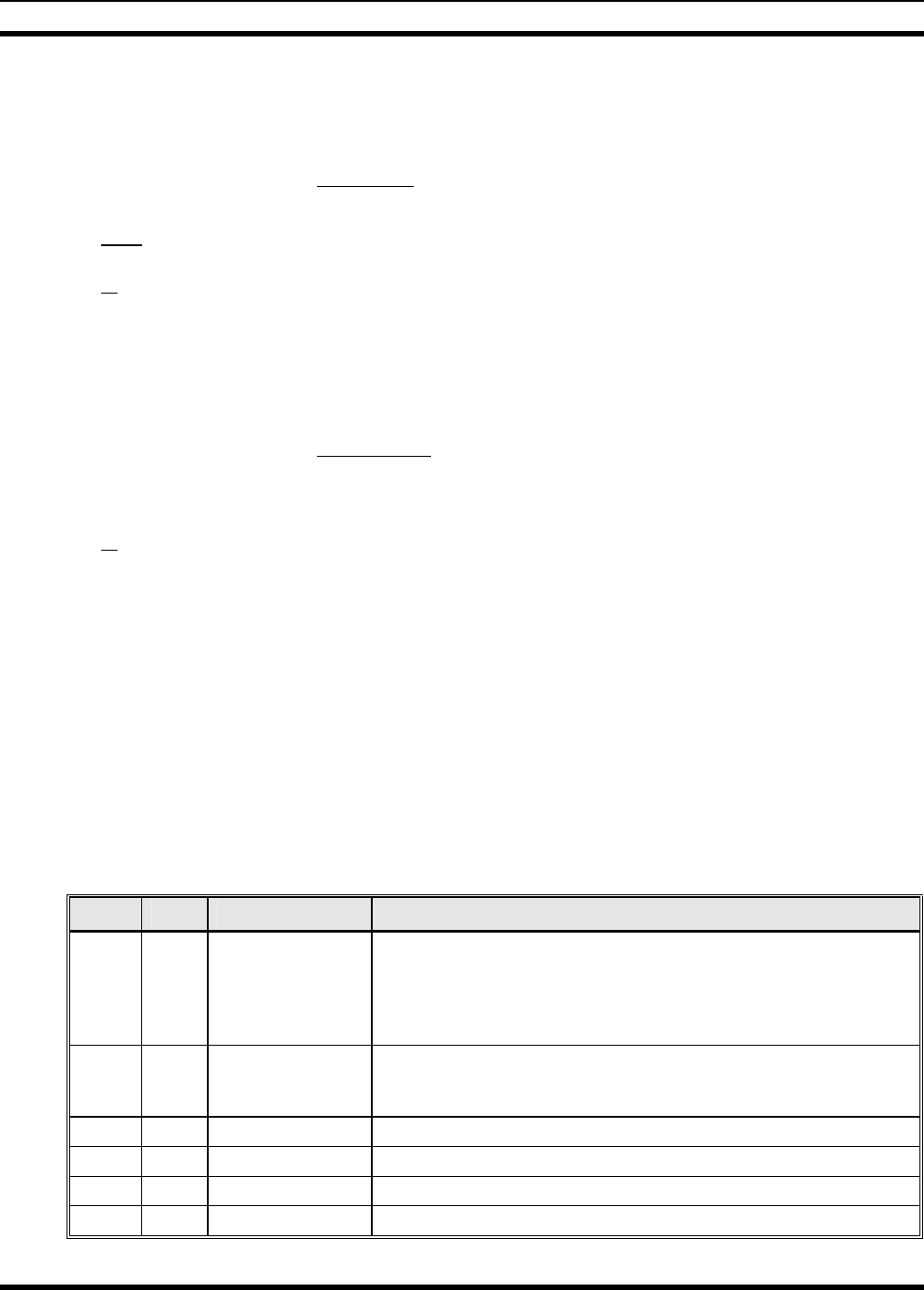
MM-014763-001
17
4 UNPACKING AND CHECKING THE EQUIPMENT
4.1 MATERIALS
A typical set of materials for a front-mount M7300 mobile radio installation includes:
• M7300 Mobile Radio, part number RU-144750-061
with:
• CH-721 Scan Control Head, part number CU23218-0001
or
CH-721 System Control Head, part number CU23218-0003)
• Standard Microphone, part number MC-101616-040
• Installation Kit MAMW-NZN6W for Front-Mount M7300 (Contents listed in Table 4-1 below)
• One or Two Antennas as listed in Table 4-3 (page 18)
A typical set of materials for a remote-mount M7300 mobile radio installation includes:
• M7300 Mobile Radio, part number RU-144750-061
• CH-721 Scan Control Head, part number CU23218-0002
or
CH-721 System Control Head, part number CU23218-0004
• Standard Microphone, part number MC-101616-040
• Installation Kit MAMW-NZN7R for Remote-Mount M7300 and CH-721 (Contents listed in
Table 4-2)
• One or Two Antennas as listed in Table 4-3 (page 18)
Table 4-2 lists the contents of Installation Kit MAMW-NZN7R available for a remote-mount M7300
mobile radio installation. Table 4-3 on page 18 lists part numbers for radio-related options and
accessories. Table 4-4 on page 20 lists options and accessories available for the CH-721 Scan and System
model control heads.
Table 4-1: Installation Kit MAMW-NZN6W
for Front-Mount M7300 Mobile Radio
ITEM QTY. PART NUMBER DESCRIPTION
1 1 KT101533V1
Kit, Front-Mount Mounting Bracket. Includes M5300/M7100/-
M7300 Mounting Bracket FM101319V1 (marked KTB0310), M5
stainless-steel hardware to attach radio to bracket, self-tapping
hardware to attach bracket to mounting surface, ½-inch rubber
grommet, and 7-inch cable ties. See Figure 7-1 on page 30.
2 1 CA-012365-001
Cable, M5300/M7300 DC Power. Includes 10-AWG, 20-Foot DC
Power Cable with straight connector, (2) waterproof HFB fuse
holders, (1) 15-amp AGC fuse and (1) 3-amp AGC fuse.
3 2 CD-014027-001 Terminator, CAN; 3-Pin, Straight Body.
4 1 LS102824V10 Speaker, External Mobile; 20-Watt (with 4.6-foot cable).
5 1 CA-012349-001 Cable, M5300/M7300 Option. See Section 11.1 (page 55).
6 1 FM-104859-001 Cap, Waterproof (For CH-721’s DB-9 serial port connector).
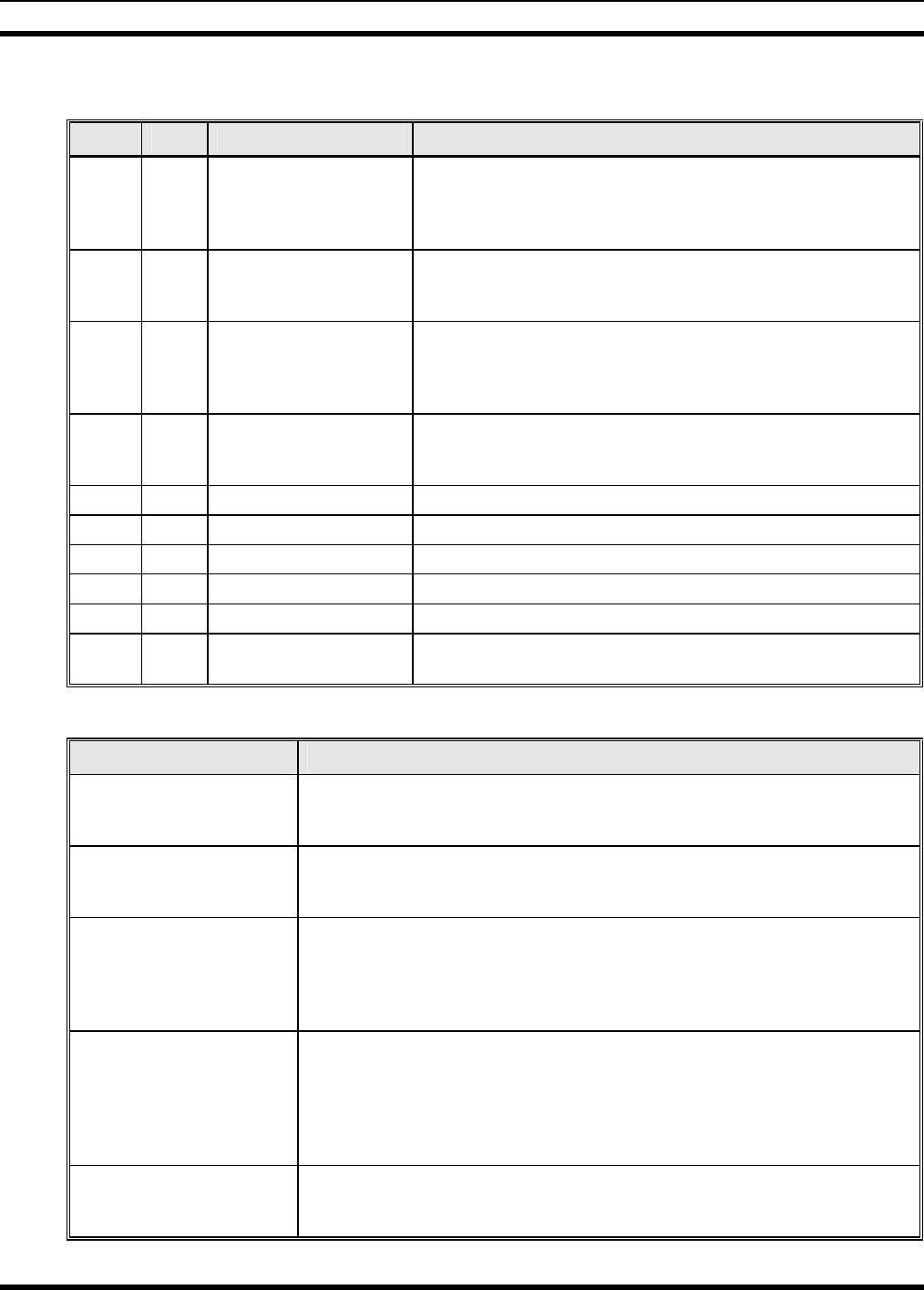
MM-014763-001
18
Table 4-2: Installation Kit MAMW-NZN7R
for Remote-Mount M7300 Mobile Radio with CH-721 Control Head
ITEM QTY. PART NUMBER DESCRIPTION
1 1 KT23117 Kit, Remote-Mount Mobile Radio Mounting Bracket. Includes
M5300/M7100/M7300 Mounting Bracket FM103111V1 and
M5 stainless-steel hardware to attach radio to bracket. See
Figure 8-2 on page 38.
2 1 KT-008608 Kit, CH-721 Mounting Bracket. Includes (1) U-Shaped
Mounting Bracket and #8 stainless-steel hardware to attach
control head to bracket.
3 1 CA-012365-001
Cable, M5300/M7300 DC Power. Includes 10-AWG, 20-Foot
DC Power Cable with straight connector, (2) waterproof HFB
fuse holders, (1) 15-amp AGC fuse and (1) 3-amp AGC
fuse.
4 1 CA-012616-001
Cable, CH-721 DC Power. Includes 12-AWG, 10-foot DC
Power Cable with straight connector, (2) waterproof HFB
fuse holders, (1) 3-amp AGC fuse, and (1) 5-amp AGC fuse.
5 2 CD-014027-001 Terminator, CAN; 3-Pin, Straight Body.
6 1 CA-009562-030 Cable, CAN; 30 feet, Right-Angle-to-Straight Connectors.
7 1 LS102824V10 Speaker, External Mobile; 20-Watt (with 4.6-foot cable).
8 1 MAMROS0034-NN006 Cable, Speaker; 6-Inch, Straight Connector.
9 1 FM-104859-001 Cap, Waterproof (For CH-721’s DB-9 serial port connector).
10 1 FM-104859-002
Cap, Waterproof (For CH-721’s DB-25 accessory
connector).
Table 4-3: Additional Options and Accessories for M7300 Mobile Radios
PART NUMBER DESCRIPTION
AN-025167-001
(Cat. No. MAMW-NAN3J) Antenna, 700/800 MHz, Standard Rooftop-Mount, 3 dB Gain, NMO
Mounting Base, 15-foot (4.6-meter) RG-58 A/U (or equivalent) Low-Loss
RF Cable, Male TNC and Mini-UHF RF Connectors; Factory-Tuned
AN-025167-002
(Cat. No. MAMW-NAN3K) Antenna, 700/800 MHz, Elevated-Feed, Rooftop-Mount, 3 dB Gain, NMO
Mounting Base, 15-foot (4.6-meter) RG-58 A/U (or equivalent) Low-Loss
RF Cable, Male TNC and Mini-UHF RF Connectors; Factory-Tuned
AN-025167-004
(Cat. No. MAMW-NAN3V) Antenna, 700/800 MHz GPS Combo, Rooftop-Mount, 3 dB Gain, NMO
Mounting Base, 15-foot (4.6-meter) RG-58 A/U (or equivalent) Low-Loss
RF Cable, Male TNC and Mini-UHF RF Connectors, 16.5-foot (5-meter)
RG174/U (or equivalent) GPS RF Cable with Male SMA RF Connector
(attached); 2.7 to 3.3 Vdc or 4.8 to 5.2 Vdc Bias; Factory-Tuned
AN-025167-005
(Cat. No. MAMW-NAN3W) Antenna, 700/800 MHz GPS Combo, Elevated-Feed Rooftop-Mount,
3 dBd Gain, NMO Mounting Base, 15-foot (4.6-meter) RG-58 A/U (or
equivalent) Low-Loss RF Cable, Male TNC and Mini-UHF RF Connectors,
16.5-foot (5-meter) RG174/U (or equivalent) GPS RF Cable with Male
SMA RF Connector (attached); 2.7 to 3.3 Vdc or 4.8 to 5.2 Vdc Bias;
Factory-Tuned
AN-025167-006
(Cat. No. MAMW-TBD) Antenna, 700/800 MHz, Magnetic-Mount, 3 dBd Gain, 15-foot (4.6-meter)
RG-58 A/U (or equivalent) Low-Loss RF Cable, Male TNC and Mini-UHF
RF Connectors; Factory-Tuned

MM-014763-001
19
Table 4-3: Additional Options and Accessories for M7300 Mobile Radios
PART NUMBER DESCRIPTION
AN-025167-010
(Cat. No. MAMW-NAN5B) Antenna, 700/800 MHz, Low-Profile, Rooftop-Mount, 2 dBd Gain, NMO
Mounting Base, 15-foot (4.6-meter) RG-58 A/U (or equivalent) Low-Loss
RF Cable, Male TNC and Mini-UHF RF Connectors, Factory-Tuned
AN-025167-011
(Cat. No. MAMW-NAN5C) Antenna, 700/800 MHz GPS Combo, Low-Profile, Rooftop-Mount, 2 dBd
Gain, NMO Mounting Base, 15-foot (4.6-meter) RG-58 A/U (or equivalent)
Low-Loss RF Cable, Male TNC and Mini-UHF RF Connectors, 16.5-foot
(5-meter) RG174/U (or equivalent) GPS RF Cable with Male SMA RF
Connector (attached); 2.7 to 3.3 Vdc or 4.8 to 5.2 Vdc Bias; Factory-Tuned
AN-025167-014
(Cat. No. MAMW-NAN5U) Antenna, 700/800 MHz, Standard Rooftop-Mount, 5 dBd Gain, NMO
Mounting Base, 15-foot (4.6-meter) RG-58 A/U (or equivalent) Low-Loss
RF Cable, Male TNC and Mini-UHF RF Connectors, Factory-Tuned
AN-025167-015
(Cat. No. MAMW-NAN5V) Antenna, 700/800 MHz GPS Combo, Rooftop-Mount, 5 dBd Gain, NMO
Mounting Base, 15-foot (4.6-meter) RG-58 A/U (or equivalent) Low-Loss
RF Cable, Male TNC and Mini-UHF RF Connectors, 16.5-foot (5-meter)
RG174/U (or equivalent) GPS RF Cable with Male SMA RF Connector
(attached); 2.7 to 3.3 Vdc or 4.8 to 5.2 Vdc Bias; Factory-Tuned
AN-025187-001
(Cat. No. MAMW-NAN5F)
Antenna, GPS Receive Only, Roof-Mount, 17-foot (5.2-meter) RG174/U
(or equivalent) RF Cable with Male SMA RF Connector (attached); 2.7 to
3.3 Vdc or 4.8 to 5.2 Vdc Bias.
AN-025187-003
(Cat. No. MAMW-NAN3L)
Antenna, GPS Receive Only, Magnetic-Mount, 17-foot (5.2-meter)
RG174/U (or equivalent) RF Cable with Male SMA RF Connector
(attached); 2.7 to 3.3 Vdc or 4.8 to 5.2 Vdc Bias.
CA-012349-001 Cable, M5300/M7300 Option. See Section 11.1 (page 55).
MAMROS0055 Cable, TIA/EIA-232 Serial Programming (6 feet).
CN-014756 Connector, RF; TNC Male Crimp-Type for RG58U, RG58A/U and RGU400
Coaxial Cable.
KT-012350-001
(Cat. No. MAMW-NMK5F) Kit, GPS Receiver for M5300/M7300.
KT-014494-001 Kit, Remote-Mount to Front-Mount Conversion.
CD-014027-001 Terminator, CAN; 3-Pin, Straight Body.
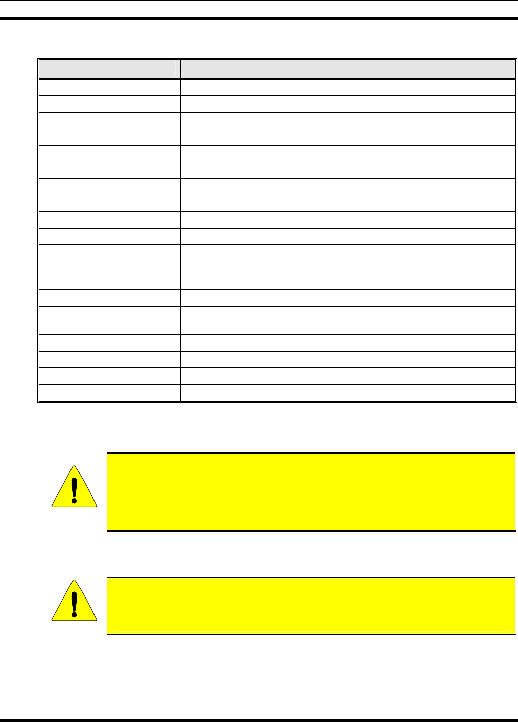
MM-014763-001
20
Table 4-4: Additional Options and Accessories for CH-721 Control Heads
PART NUMBER DESCRIPTION
CA-009562-006 Cable, CAN; 6 feet, Right-Angle-to-Straight Connectors
CA-009562-030 Cable, CAN; 30 feet, Right-Angle-to-Straight Connectors
CA-009562-090 Cable, CAN; 90 feet, Right-Angle-to-Straight Connectors
CA-009562-250 Cable, CAN; 250 feet, Right-Angle-to-Straight Connectors
CA-011854-001 Cable, CH-721 Option
CA-104861 Cable, CH-721 Programming
MAMROS0075-N1210 Cable, DC Power; 12-AWG, 10-Foot, Straight Connector
MAMROS0075-N1220 Cable, DC Power; 12-AWG, 20-Foot, Straight Connector
MAMROS0075-R1210 Cable, DC Power; 12-AWG, 10-Foot, Right-Angle Connector
MAMROS0075-R1220 Cable, DC Power; 12-AWG, 20-Foot, Right-Angle Connector
MACDOS0012 Kit, Control Head Pedestal Mounting. Includes Pedestal Mount and
Mounting Screws
MACDOS0013-CN004 Kit, Speaker; 20-Watt, Straight Connector
MACDOS0013-CR004 Kit, Speaker; 20-Watt, Right-Angle Connector
MC-101616-040 Microphone, Standard with Conxall Flush-Mount Connector
(Included with catalog number MAMW-NMC7Z)
MC-103334-040 Microphone, DTMF with Conxall Flush-Mount Connector
MC-103334-050 Microphone, Noise-Canceling with Conxall Flush-Mount Connector
344A4678P1 Microphone Hanger. (Included with catalog number MAMW-NMC7Z)
MACDOS0010 Terminator, CAN; 3-Pin, Right-Angle Body
4.2 MATERIAL INSPECTION
CAUTION
After removal from the carton, examine the radio, control head and other components
for broken, damaged, loose or missing parts. If any are noted, contact M/A-COM’s
Customer Resource Center (see page 16) immediately to discuss and arrange the return
of the equipment to M/A-COM for replacement. Any unauthorized attempts to repair or
modify this equipment will void the warranty and could create a safety hazard.
Upon removing items from the carton and verifying that all equipment is accounted for, proceed with the
installation.
CAUTION
Mounting of the radio, control head, and/or antenna in ways other than those described
in this manual may adversely affect performance, violate FCC rules on RF exposure,
and even damage the unit, posing a potential safety hazard.
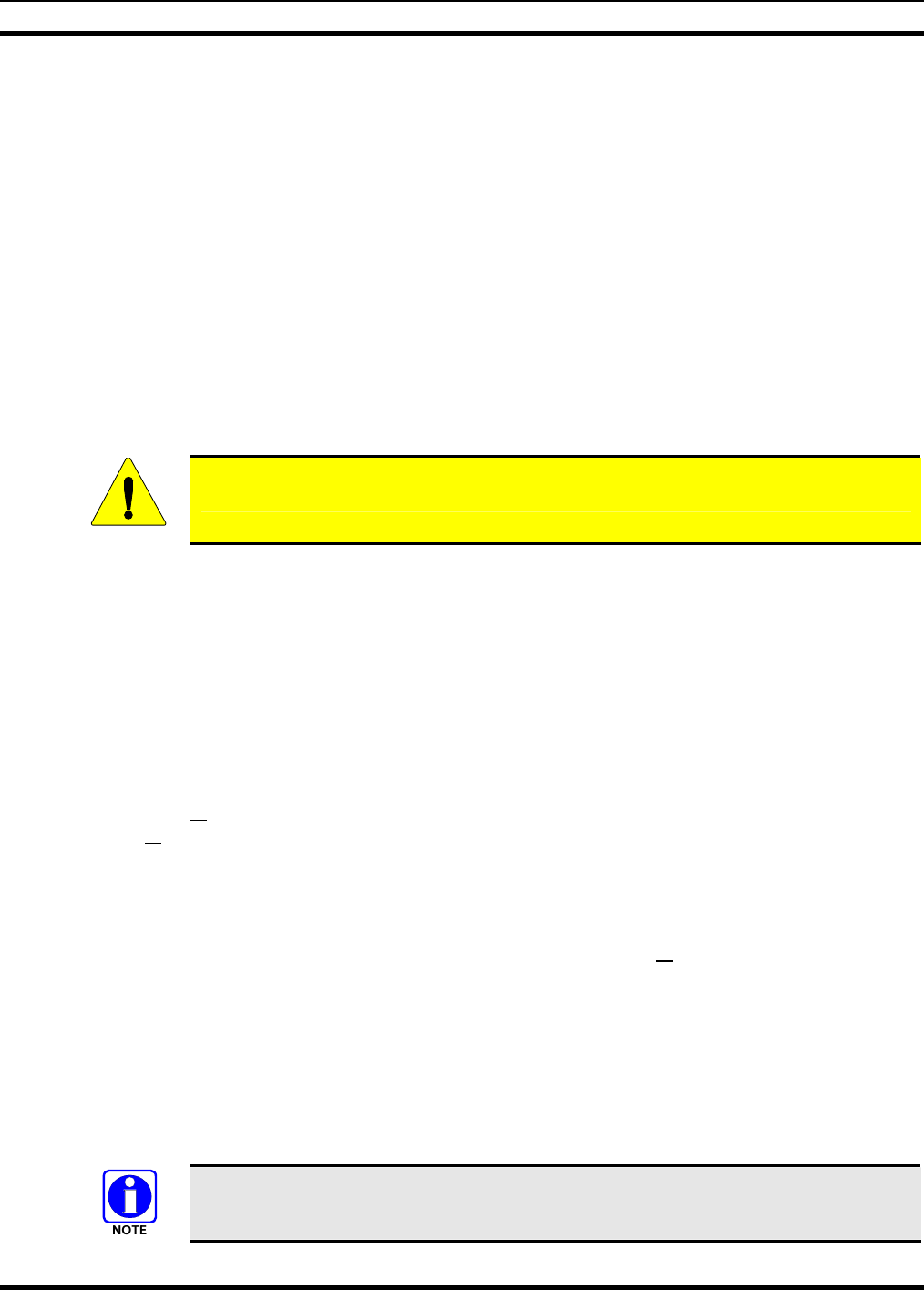
MM-014763-001
21
5 PLANNING THE INSTALLATION
5.1 GENERAL INFORMATION
Figure 5-1 on page 22 illustrates a typical front-mount radio installation, and Figure 5-2 on page 22
illustrates a typical remote-mount radio installation. Before starting, plan the installation carefully so it
will meet the following requirements:
• The installation is safe for the operator and passengers within the vehicle.
• The equipment is installed away from the airbag deployment areas.
• The installation allows for convenient access by the operator, as applicable (i.e., the control head).
• The equipment is protected from water damage.
• The installation is neat and allows easy service access.
• The mobile radio is mounted in a location assuring the vehicle occupant’s safety and out of the way
of passengers and auto mechanics.
CAUTION
A professional radio installer should perform the installation!
5.2 TOOLS REQUIRED
The following tools are recommended to complete the installation. Where specific vendor names and
model or part numbers are given, equivalent substitutes may be used:
• Non-Insulated Crimp Tool: Thomas & Betts
WT-111-M
• Phillips-Head Screwdrivers, #1 and #2
• Insulated Terminal Crimp Tool: Klein 1005 • Flat-Blade Screwdrivers, #1 and #2
• Fuse Holder Crimp Tool: Thomas & Betts –
WT-112M or California Terminal Products No.
1250 or Channelock No. 909
• 4-Millimeter Hex Key Wrench
• 1/8-Inch Hex Key Wrench (Allen Wrench)
• Ratcheting Coaxial Crimp Tool: Cambridge
24-9960P
• Two 5/16-Inch Combination or Open-End
Wrenches (Needed for GPS Receiver Option)
• Non-Metallic Fish Tape, 25-Foot: Klein-Lite
50156
• ¾-Inch Hole Saw with Depth Protection:
Ripley HSK 19 or Antenex HS34
• Various Socket and Driver Sets • Clutch-Type Screw Cordless Gun/Drill with
Driver Bits: Makita #6096DWE
• Soft-Jaw Pliers: Tessco 450520 or equivalent • Cordless Electric Drill with Bits
• Various Fasteners (e.g., machine screws and
nuts, Tek screws, etc.)
• Deburring Tool (for ⅜-inch and smaller holes)
• Tie Wraps: 6-inches or larger • Flush-Cut and Large Wire Cutters
A separate list of test equipment is included in Section 14.2 on page 64.
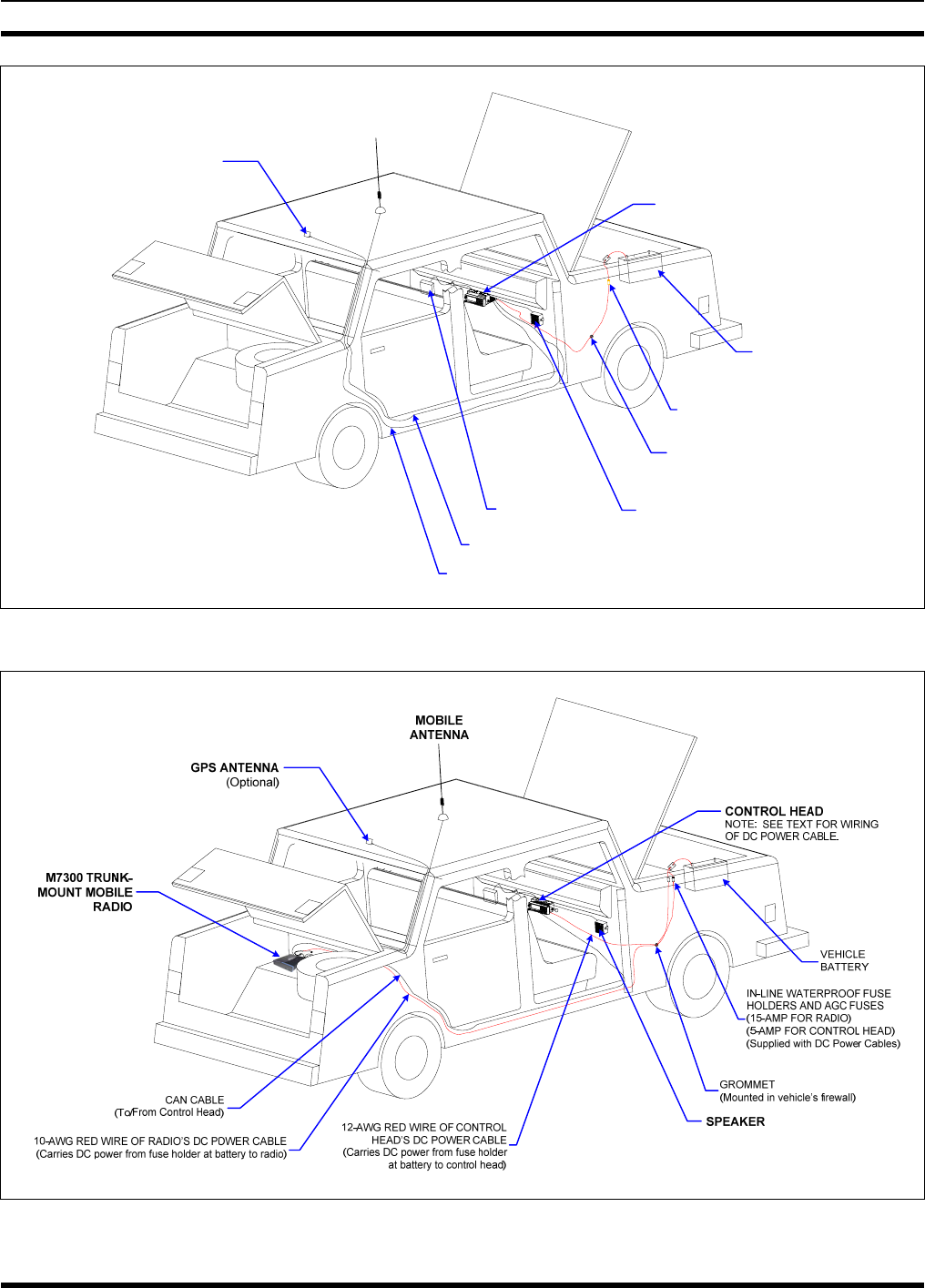
MM-014763-001
22
VEHICLE
BATTERY
GROMMET
(MOUNTED IN FIREWALL)
SPEAKER
IN-LINE WATERPROOF FUSE
HOLDER & AGC FUSE
(20-AMP FOR RADIO)
MOBILE
ANTENNA
GPS ANTENNA
M7300 FRONT-MOUNT
MOBILE RADIO
VEHICLE
FUSE BOX
GPS ANTENNA CABLE
MOBILE ANTENNA CABLE
Figure 5-1: Typical Front-Mount Mobile Radio Installation in a Standard Passenger Vehicle
Figure 5-2: Typical Remote-Mount Mobile Radio Installation in a Standard Passenger Vehicle
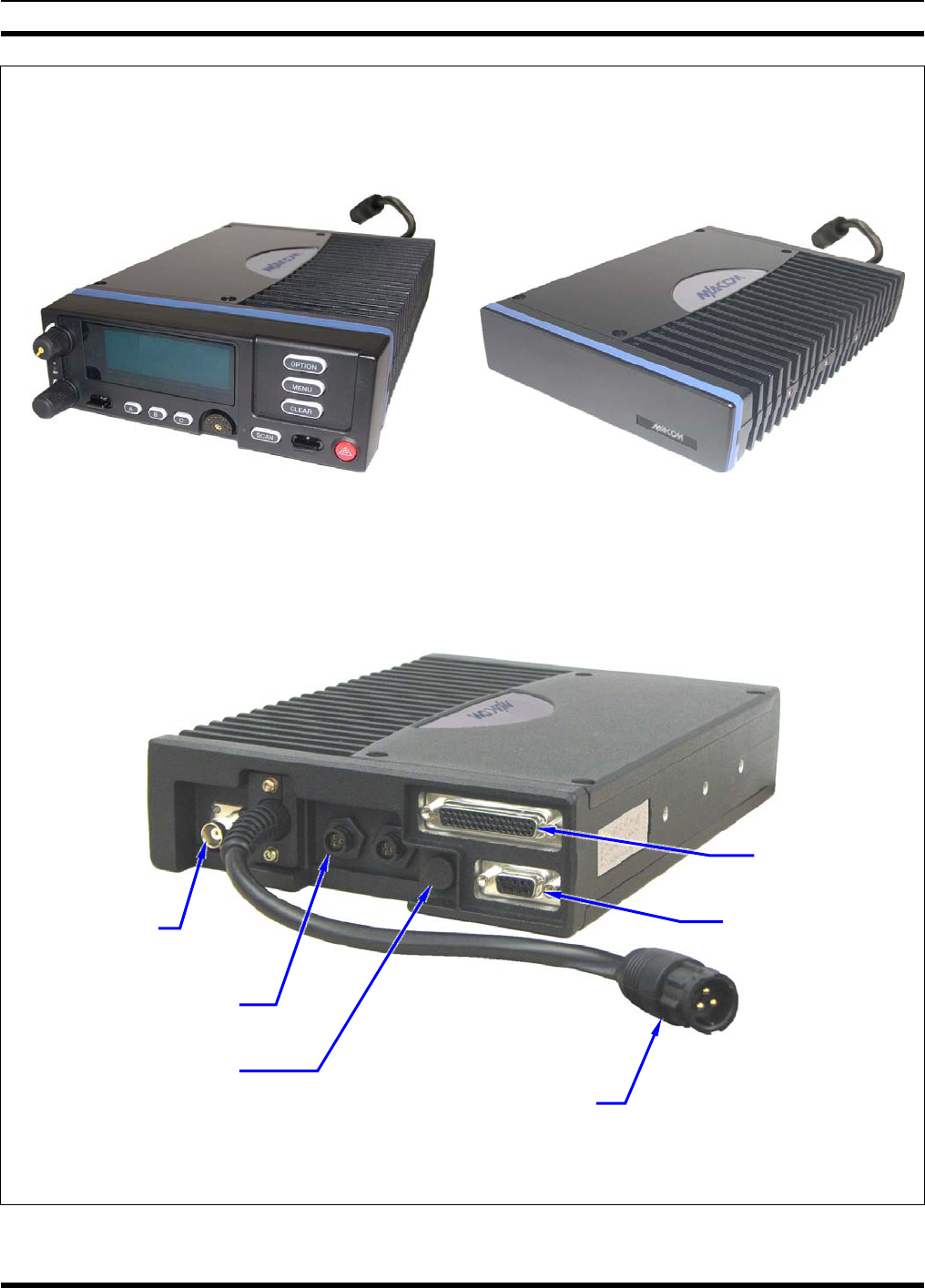
MM-014763-001
23
FRONT VIEWS
Front-Mount M7300 Mobile Radio Remote-Mount M7300 Radio
(With Scan Control Head)
REAR VIEW
(Enlarged)
Figure 5-3: M7300 Front-Mount and Remote-Mount Mobile Radios — Front and Rear Views
CAN Port Connectors
(2 places)
Antenna
Connector
(female TNC)
DC Power Cable
(with 3-Pin Connector)
GPS Antenna Port
(optional)
44-Pin I/O
Connector
9-Pin Serial Port
Connector
MM-014763-001
24
5.3 LOCATING COMPONENTS
Plan the mounting locations of all components (radio, control head, antenna, and cables) and determine
the routes for all wiring and cables. Particularly consider the connection of the radio for planning
purposes.
• Determine the customer’s preferences, if any, for location of components. Comply with these
preferences as long as they are consistent with safety recommendations and guidelines presented in
this manual, and other generally accepted professional radio installation practices.
• For a front-mount installation, the radio is typically located under the vehicle’s dash panel. However,
it may be mounted above the dash, or at some other location per customer requirements, available
space, and/or mounting surface strength. Radio and control head dimensions are listed in Section 2.1
on page 12. As noted in that section, these dimensions do not include space required at the rear of the
radio for cables. Several inches of clearance space is required.
• For a remote-mount radio installation, the radio is typically located in the motor vehicle’s trunk, or
some other preferably unoccupied section in a vehicle, such as a fire truck’s equipment shelf, and the
control head is typically located under the vehicle’s dash panel. Radio and control head dimensions
are listed in Section 2.1 on page 12. As noted in that section, these dimensions do not include space
required at the rear of the radio and control head for cables. Several inches of clearance space is
required at the back of the control head, and at least six (6) inches is recommended at the back of the
radio. In addition, several inches of clearance space is required at each side of the radio for access to
the screws that secure the radio to its mounting bracket.
• When selecting a mounting location, verify sufficient clearance behind the radio can be maintained so
cables will not be stressed, crushed, twisted, or bent at severe angles. This also applies to the control
head in a remote-mount radio installation. Also, the front and sides of the units must have clearance
for air circulation, access to mounting screws, mounting hardware, etc.
• Verify the drilling of holes and the insertion of screws will not damage or interfere with any existing
vehicle components (for example, a fuel tank, fuel lines, the transmission housing, etc.), or any
existing vehicle wiring.
• For antenna location and installation-related information, refer to Section 6.
CAUTION
The radio must be kept out of direct sunlight and away from heat sources. Adequate
free-air ventilation must be provided to its rear fins. The radio will automatically
reduce its transmit RF output power when its ambient temperature exceeds
approximately +140° Fahrenheit (+60° Celsius).
CAUTION
All cables should have a service loop near each connector end. Do not bend the cables
at severe angles near the connector end. Above all, after all components are installed,
verify no cable is under any tension. Failure to do so may lead to damaged cables,
causing intermittent radio operation or complete radio failure.
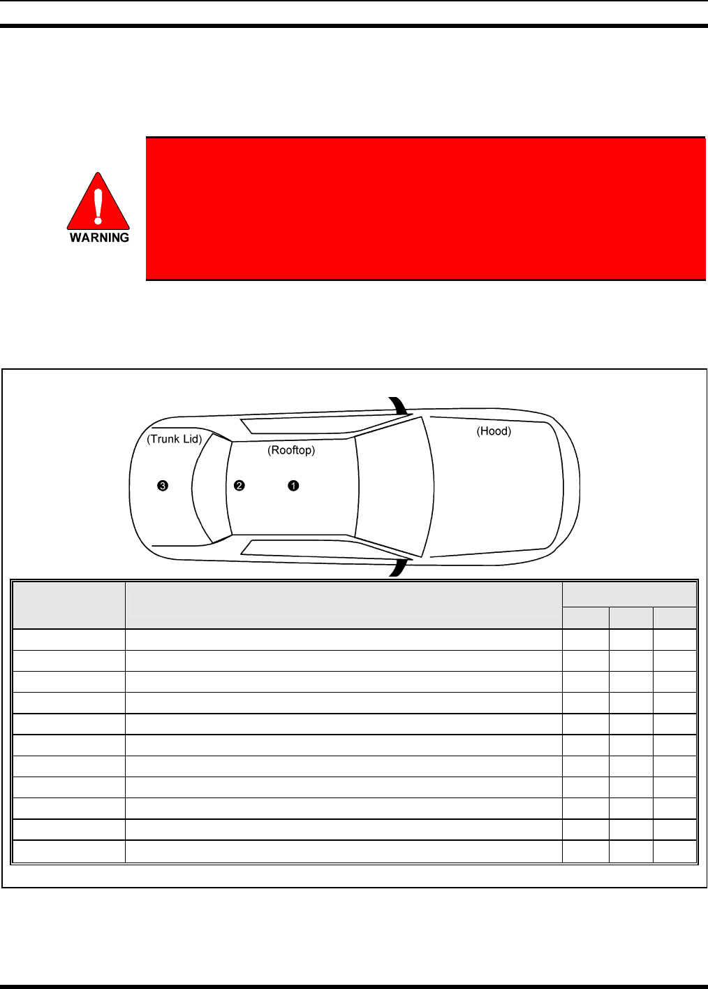
MM-014763-001
25
6 ANTENNA INSTALLATION
6.1 ANTENNA MOUNTING LOCATIONS
At this time, review all information presented in the REGULATORY AND
SAFETY INFORMATION section of this manual (see page 6). A transmitting
antenna must be installed in accordance with the guidelines presented in the
REGULATORY AND SAFETY INFORMATION section. Use Table 1-1 on page 8
and Figure 6-1 below as a guide for determining the best possible mounting
configuration/location in order to reduce human exposure to radio frequency (RF)
electromagnetic energy during transmit mode.
Antennas must be mounted in one of three possible locations on the vehicle as described in the following
subsections. Figure 6-1 shows the recommended locations and antenna part numbers for each location.
Also, see Table 4-3 for additional information. Always follow the antenna manufacturer’s instructions
when mounting an antenna.
TOP VIEW OF A TYPICAL VEHICLE
LOCATION(S)
ANTENNA
PART NO.* ANTENNA DESCRIPTION p o n
AN-025167-001 700/800 MHz Standard Rooftop-Mount, 3 dBd Gain 9 9
AN-025167-002 700/800 MHz Elevated-Feed Rooftop-Mount, 3 dBd Gain 9 9 9
AN-025167-004 700/800 MHz GPS Combo Rooftop-Mount, 3 dBd Gain 9 9
AN-025167-005 700/800 MHz GPS Combo Elevated-Feed Rooftop-Mount, 3 dBd Gain 9 9 9
AN-025167-006 700/800 MHz Magnetic-Mount, 3 dBd Gain 9
AN-025167-010 700/800 MHz Low-Profile Rooftop-Mount, 2 dBd Gain 9 9
AN-025167-011 700/800 MHz GPS Combo Low-Profile Rooftop-Mount, 2 dBd Gain 9 9 9
AN-025167-014 700/800 MHz Standard Rooftop-Mount, 5 dBd Gain
9
AN-025167-015 700/800 MHz GPS Combo Rooftop-Mount, 5 dBd Gain
9
AN-025187-001 GPS Receive Only, Roof-Mount 9 9
AN-025187-003 GPS Receive Only, Magnetic-Mount 9 9
* See Table 4-3 on page 18 for the respective antenna catalog numbers.
Figure 6-1: Recommended Antenna Mounting Locations with Antenna Part Numbers
MM-014763-001
26
6.1.1 Direct Center or Center-Rear of Rooftop
The center of the vehicle’s roof is the best location for a rooftop-mount antenna (location n in Figure
6-1). For optimal performance, the mounting area under the antenna must be a flat with a minimum
radius of six (6) inches of metal ground plane. It must be located directly in the center of the roof to
minimize human exposure to RF electromagnetic energy. Other obstructions such as a light bar or another
antenna may prevent the antenna from being mounted in the direct center of the roof. In this case, the
antenna should be mounted a minimum of one foot away from and behind the obstruction but in the
middle of the roof with respect to the left and right sides of the vehicle (location o in Figure 6-1).
6.1.2 Center of Trunk Lid
Certain vehicles do not allow for the antenna to be placed in the center or center-rear of the roof. In this
case, the next best location for the antenna is in the direct center of the trunk lid (location p in Figure
6-1). In this case, an elevated-feed-point antenna is recommended. Although this type of antenna does
not require a metal ground plane, it must be located directly in the center of the trunk lid to minimize
human exposure to RF electromagnetic energy.
6.2 ANTENNA INSTALLATION PROCEDURE
An antenna must be installed before completing the radio installation.
6.2.1 Install the Mobile Antenna
Table 4-3 (page 18) and Figure 6-1 (page 25) list the mobile radio antennas available for use with the
radio. As presented in the previous section, various mounting locations exist. Optimal performance is
achieved via a rooftop antenna mounted in the direct center of the motor vehicle’s roof. The following
mobile antenna installation procedure is recommended:
1. Once the mounting location is selected, refer to the antenna manufacturer’s mounting and testing
instructions included with the antenna kit for installation guidance. Install the antenna in accordance
with these instructions. If necessary, contact M/A-COM’s Technical Assistance Center. See page 16
for TAC contact information.
The antenna cable of M/A-COM approved antennas should never be cut to a
shorter length. Instead, excess cable must be tied and stowed. This not only
prevents the antenna from radiating above its intended or configured power, but
it also allows for future installation considerations such as a relocation of the
mobile radio within the vehicle. Installations requiring longer cables are treated
as custom and separately specified.
2. Route the cable from the antenna base to the location of where the mobile radio will be installed.
Remove headliner panel, interior panels, etc., as necessary. The cable must be kept out of casual
contact from persons within the vehicle. Tie and stow the cable as necessary to protect it from
possible chafing.
3. Using an appropriate crimp tool, crimp the supplied TNC RF connector to the end of the antenna
cable. For crimping instructions, see Figure 6-2 or the instructions supplied with antenna.
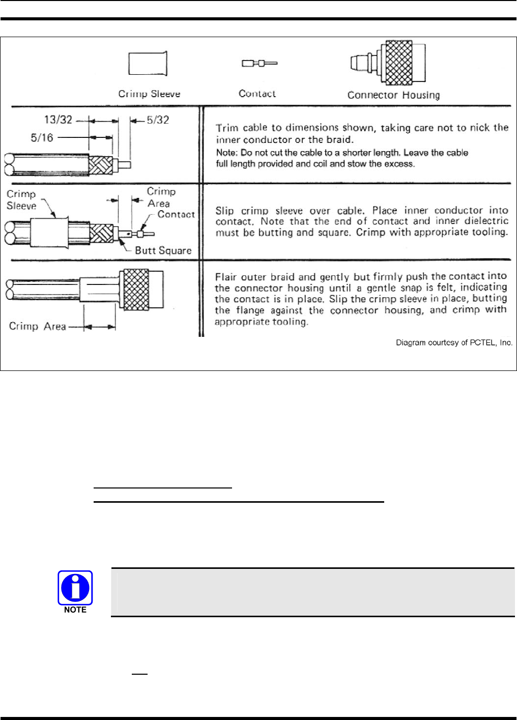
MM-014763-001
27
Actual Size; Dimensions are in Inches
(VS-AN-025167-010 Rev. A)
Figure 6-2: Crimping Instructions for TNC RF Connector
4. The antenna cable is connected to the radio’s TNC receptacle-type (female) RF connector per a
procedure presented later in this manual. The cable and its TNC connector must be protected from
damage, dirt, and/or metal shavings which may be generated during the mechanical and electrical
installation of the radio. Temporarily tying the connector and cable-end within a small plastic bag is
recommended.
6.2.2 Install the GPS Antenna
(Required Only if Radio has GPS Receiver Option)
If the M7300 radio is equipped with the GPS receiver option, the GPS receiver requires connection to an
externally-mounted GPS antenna. The GPS antenna must be kept at least six (6) inches away from any
other antenna mounted on the vehicle and it must have at least six inches of surface ground plane beneath
it. The following antenna installation procedure is recommended:
A combination (“combo”) antenna kit includes a GPS antenna built into the base of the
mobile antenna. Refer to Table 4-3 (page 18) and/or Figure 6-1 (page 25) for available
combo antennas.
1. Once the mounting location is selected, refer to the antenna manufacturer’s mounting and testing
instructions for installation guidance. Install the antenna in accordance with these instructions. If
necessary, contact M/A-COM’s Technical Assistance Center. See page 16 for TAC contact
information. Do not alter the GPS antenna cable length; tie and stow excess cable as necessary.

MM-014763-001
28
2. Route the cable from the antenna base to the location of where the radio will be installed. Remove
headliner panel, interior panels, etc., as necessary. The cable must be kept out of casual contact from
persons within the vehicle. Tie and stow it as necessary to protect it from possible chafing.
3. The antenna cable is connected to the radio’s SMA receptacle-type (female) RF connector per a
procedure presented later in this manual. The cable and its (male) SMA connector must be protected
from damage, dirt, and/or metal shavings which may be generated during the mechanical and
electrical installation of the radio. Temporarily tying the connector and cable-end within a small
plastic bag is recommended.
MM-014763-001
29
7 FRONT-MOUNT RADIO INSTALLATION
This section includes detailed instructions for mechanically installing and wiring a
front-mount M7300 mobile radio. For remote-mount M7300 mobile radio installation
procedures, refer to Section 8 which begins on page 36.
7.1 MOUNTING THE FRONT-MOUNT RADIO
The Mounting Bracket Kit for the front-mount M7300 mobile radio includes a heavy-gauge steel
U-shaped mounting bracket. The radio should be attached to a mounting surface using this bracket. The
bracket can be mounted above or below the radio. Kit contents are shown in Figure 7-1, and bracket
dimensions are shown in Figure 7-2.
Both the radio and the mounting bracket have multiple holes in both sides for adjusting the radio within
the bracket. The design allows for both front-to-rear tilting of the radio within the bracket for best viewing
angle, and a front-to-rear position offset. The radio has six (6) threaded mounting holes, three (3) per side,
and the mounting bracket has ten (10) corresponding holes, five (5) per side. The radio must be secured to
the bracket using at least four of the six M5 socket-head screws included in the Mounting Bracket Kit (2
screws per side).
Typically, the radio is front-to-rear centered within the bracket. However, it can be front-to-rear offset by
approximately 2 inches (5.1 centimeters), if required. Also, the radio can be positioned straight in the
bracket (i.e., parallel with the bottom surface of the bracket), or it can be tilted up or down at an angle of
between approximately 10 to 20 degrees. When positioned straight and centered front-to-rear within the
bracket, the radio extends approximately 2.5 inches (6.4 centimeters) from the front and rear edges of the
bracket. In the rear, additional clearance must be included for cables. The area directly at the front of the
radio must be completely clear of all objects (e.g., gear shift, other radio equipment, etc.) so the operator
can easily access and visualize the radio’s control head.
The mounting bracket must be attached to a secure metal surface that meets or exceeds the minimum
1/16-inch-thick steel sheet metal requirement in accordance with the following WARNING. For example,
it can be attached directly to the bottom of the dash if the gauge of the sheet metal is high and the surface
is firm and flat, or it can be attached to the transmission hump, etc., if a mounting wedge (not included) is
utilized. The front-mount M7300 radio weighs approximately 9.2 pounds (4.17 kilograms).
At a minimum, the mounting surface should be 16-guage (approximately 1/16-inch
thick) steel sheet metal. Mounting to plastic or other material with low tensile and
shear strength could lead to an unsafe and/or failed mounting condition, turning
the radio and its mounting bracket into a projectile during a high-shock incident
such as a motor vehicle accident. If the selected mounting surface does not meet
the minimum 16-guage steel sheet metal requirement, the surface should be
reinforced with a metal backing plate (not supplied) or it should be reinforced
using some other approved mounting method.
CAUTION
In addition to improving safety of the installation, firm mounting also prevents
unreasonable vibration that could damage the radio, adversely affect transceiver
performance and/or cause its cable connections to loosen. An improperly mounted
M7300 radio may experience degradation in the quality of voice and data
communications.
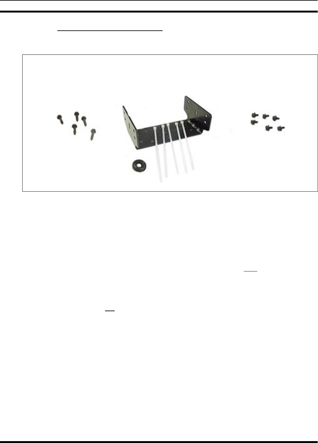
MM-014763-001
30
7.1.1 Mounting Bracket Installation
The front-mount M7300 radio’s mounting bracket is included with the Remote-Mount Mounting Bracket
Kit KT101533V1. Kit contents are shown in Figure 7-1. This kit is Item 1 listed in Table 4-1 (page 17).
Mounting Bracket
Self-Tapping Screws for FM101319V1
Securing Bracket (Marked KTB0310), M5 Hardware for
to Mounting Surface Ties and Grommet Securing Radio to Bracket
Figure 7-1: Front-Mount Mounting Bracket Kit KT101533V1
When selecting a mounting location for the radio, verify sufficient clearance can be maintained around
the radio for installation and service access. A minimum clearance of approximately 4 inches
(10 centimeters) is recommended at the rear, left and right sides of the radio. As previously stated, the
area directly at the front of the radio must be completely clear of objects so the operator can easily access
and visualize the radio’s control head.
As illustrated in Figure 7-2, the bracket is both left-to-right and front-to-rear symmetrical. It has eleven
(11) holes for securing it to a mounting surface. At least four (4) of these holes must be used to secure the
bracket to the mounting surface. Five 20-millimeter-long self-tapping screws are included in the
Mounting Bracket Kit for this purpose. However, some other type of hardware (not supplied) may be
used, such as #10-32 stainless-steel self-locking hardware (i.e., machine screws with washers and locking
nuts), or self-drilling screws. Self-drilling screws such as “TEK” screws do not require drilling of a pilot
hole prior to installation. Do not use common self-threading sheet metal screws because they will loosen
over time with vehicle vibrations.
The following mounting procedure is recommended:
1. Determine the best radio-to-bracket position and angle by test-fitting the radio into the mounting
bracket at the selected vehicle mounting location. Slide the radio between the sides of the bracket and
temporarily secure it to the bracket with several of the M5 socket-head screws from the bracket kit.
When positioned straight and centered front-to-rear within the bracket, the radio extends
approximately 2.5 inches (6.4 centimeters) from the front and rear edges of the bracket. In the rear,
additional clearance must be included for cables. The area directly at the front of the radio must be
completely clear of all objects (e.g., gear shift, other radio equipment, etc.) so the operator can easily
access and visualize the radio’s control head.
2. At the rear of the radio, verify sufficient clearance is available for cables and service access.
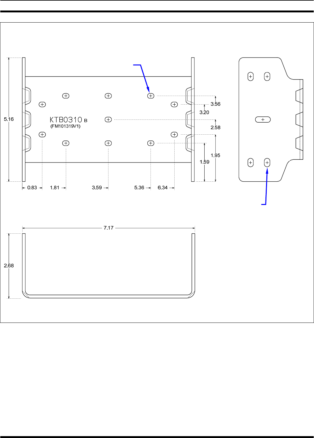
MM-014763-001
31
TOP VIEW SIDE VIEW
(Dimensions in Inches)
FRONT/REAR VIEW
(Dimensions in Inches)
(Made From KBT0310B)
Figure 7-2: Mounting Bracket FM101319V1 (Marked KTB0310) Dimensions
[for Front-Mount M7300 Mobile Radio (Radio Not Shown)]
3. If the mounting surface is not flat (such as the top of a transmission hump), construct a suitable
mounting wedge as necessary, and attach the wedge to the surface using an approved attachment
method. Never mount the bracket directly to a non-flat surface.
4. On the mounting surface, mark the selected location for the bracket, and then remove the radio from
the bracket.
5. Clean and remove any foreign material from the mounting surface.
Bracket-To-Vehicle
Screw Holes (11 places)
Bracket-To-Radio Screw Holes
(10 places,5 each side)
MM-014763-001
32
6. Using the bracket as a template, and/or the dimensional information shown in Figure 8-3, mark and
drill at least four (4) mounting holes into the mounting surface as required per the type of hardware
used.
CAUTION
Before drilling holes and/or installing mounting screws, verify these operations will not
damage or interfere with any existing vehicle component (the fuel tank, a fuel line, the
transmission housing, existing vehicle wiring, etc.). Always check to see how far the
mounting screws will extend below the mounting surface prior to installation. Always
deburr drilled holes before installing screws.
7. Temporarily remove the bracket and deburr all of the newly drilled holes.
8. If necessary, apply an approved paint or rust-inhibitor at the holes in the mounting surface.
9. Set the bracket back into place.
10. Install and tighten the mounting screws/hardware.
11. Verify the bracket is firmly secured to the mounting surface. A secure mount prevents unreasonable
vibration, which could damage the radio and/or cause its cable connections to loosen.
12. If the rear of the radio is easily accessible when the radio is positioned in the selected position within
the bracket, it is recommended that the radio be temporarily inserted into the bracket. Otherwise, do
not mount the radio into the bracket at this time, because several cable connections must be made at
the rear of the radio.
7.1.2 Inserting the Radio into the Mounting Bracket
The radio should now be inserted into the mounting bracket according to this procedure:
1. Lay the radio into the mounting bracket with the front of the radio facing in the correct direction
(usually towards the rear of the vehicle).
2. Secure the radio to the bracket using at least four (4) of the six (6) M5 x 10 mm stainless-steel socket-
head screws included with the Mounting Bracket Kit. These screws have captive lockwashers. Kit
contents are shown in Figure 7-1. This kit is Item 1 listed in Table 4-1 (page 17).
3. Tighten all screws using a 4-millimeter hex key wrench until each lockwasher is fully compressed
and the radio is firm and flush in between the brackets.
4. Check the mounting area for proper clearance for cable service looping and for air circulation, plus an
area to secure and rest the excess cable lengths.
Proper mounting is one factor that ensures optimal radio performance. An improperly
mounted radio may experience degradation in the quality of voice and data
communications.
7.2 FRONT-MOUNT RADIO’S DC POWER INSTALLATION
7.2.1 Overview of On/Off Power Wiring Configurations
The following power wiring configurations are supported:
• Radio turns on and off automatically with vehicle’s ignition switch/key — This configuration
allows the on/off state of the vehicle’s ignition switch/key to control the on/off power state of the

MM-014763-001
33
radio. The white wire of the radio’s DC Power Cable is connected to a fused switched power source,
typically identified as vehicle “Accessory” power. This source must switch on (up to positive (+)
battery voltage potential) when the vehicle’s ignition switch/key turns on, and it must switch off (to
near zero volts) when the ignition switch/key turns off. The required fuse rating is 3 amperes. When
using this configuration, the on/off/volume control must be left in the on position for automatic
power-up/down to function properly.
In a front-mount M7300 radio installation, to fuse the white wire of the radio’s DC
Power Cable, a waterproof (HFB type) fuse holder and a 3-amp AGC fuse are included
with the cable.
• Radio turns on and off with a manual switch — This configuration is used when, for example, the
radio must remain on even when the ignition key must be removed from the vehicle and a separate
on/off switch is acceptable. The white wire of the radio’s DC Power Cable is connected to one side of
a manually-controlled switch, and the other side of this switch is connected to unswitched and fused
vehicle power. The required fuse rating is 3 amperes. When using this configuration, the
on/off/volume control must be left in the on position for automatic power-up/down to function
properly.
• Radio turns on with its on/off/volume control (“hot wired”) — This configuration allows radio
on/off power control only via its on/off/volume control. It may be desired if, for example, the radio
must remain on even when the ignition key must be removed from the vehicle and a separate on/off
switch is not desired and/or not acceptable. The white wire of the radio’s DC Power Cable must be
connected to unswitched and fused vehicle power. The required fuse rating is 3 amperes.
In all of the above cases, the radio’s main DC power input (red wire) must be connected through an in-
line fuse to unswitched vehicle DC power. The red wire must be connected to raw battery power (positive
battery terminal) via the supplied fuse.
7.2.2 DC Power Cable and Main Fuse Holder Installation
The radio’s DC Power Cable has a 3-pin connector, a 20-foot red wire (for the main power connection), a
20-foot white wire (for the switched power source connection), and a 4-foot black wire (for the ground
connection). It is supplied with waterproof fuse holders, two AGC-type fuses, and non-insulated ring
terminals. The following installation procedures are recommended:
7.2.2.1 Black Wire Connection (Ground Wire)
1. Connect the radio’s DC Power Cable to the radio by mating its 3-pin connector to the radio’s 3-pin
power cable connector as follows: Visually align the key and firmly push and turn the outer locking
ring clockwise until it stops. A click will be sensed to confirm proper mating.
2. Prepare to connect the cable’s black wire to vehicle ground by locating an area of vehicle metal
within approximately two (2) feet of the radio. This surface must have a solid and stable connection
to vehicle ground. If not, add grounding strap(s) as necessary.
3. Strip the area of any paint or dirt to expose a bare metal surface, approximately ¾-inch square.
4. Drill a hole in the approximate center of the bare metal surface, and deburr it. A ⅜-inch non-
insulated ring terminal is supplied with the cable to make this ground connection. Therefore, hole
diameter should be appropriate for the utilized grounding screw/bolt size and type used to connect the
ring terminal to the bare metal surface. This hardware is not supplied.
5. Cut the black wire to the required length plus some additional length for a service loop, then strip
insulation back approximately ¼-inch.
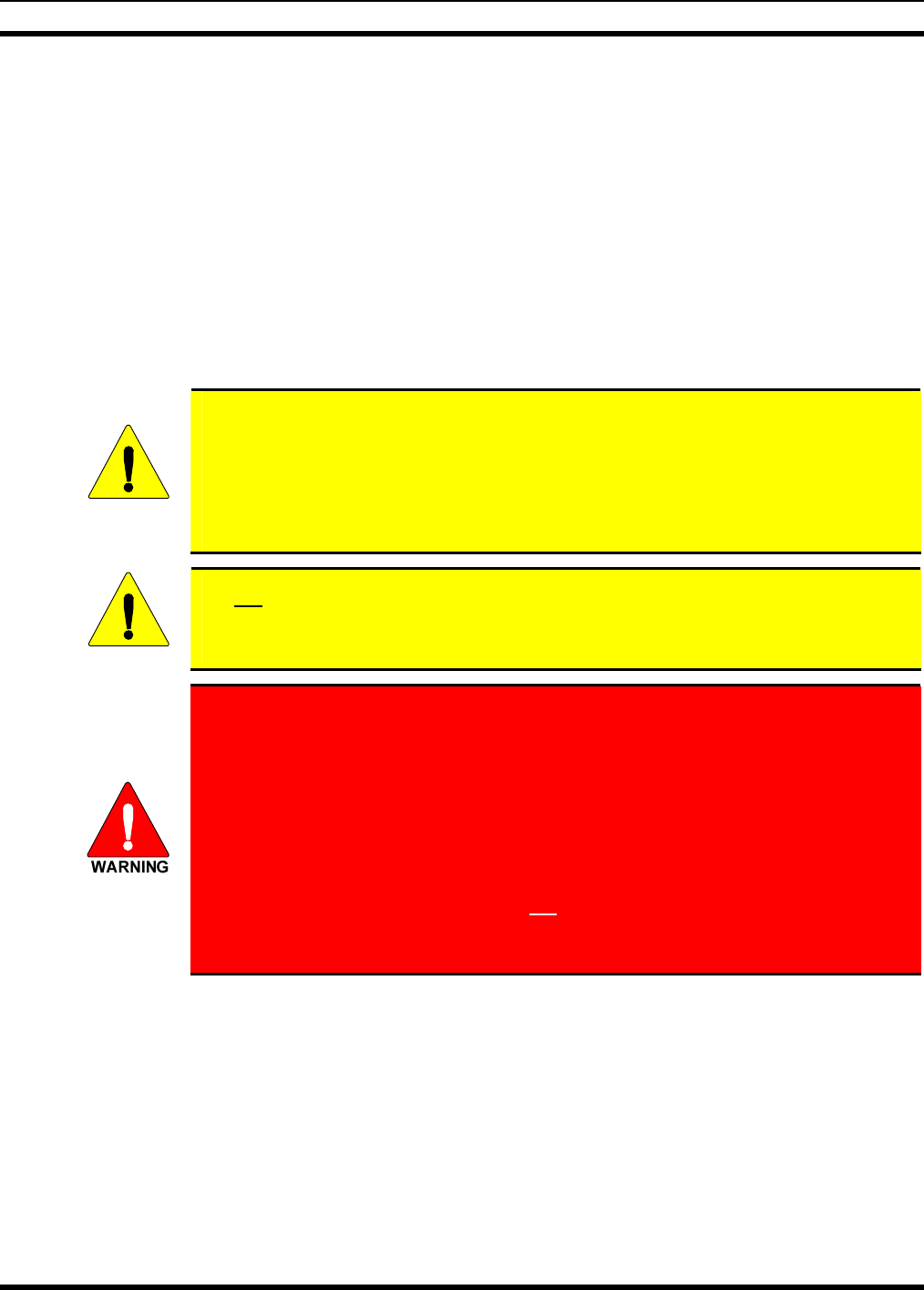
MM-014763-001
34
6. Crimp a ⅜-inch non-insulated ring terminal (supplied with the cable) to the end of the black wire.
7. Attach the ring terminal and black wire to the bare metal surface using stainless-steel self-locking
hardware (i.e., machine screws with washers and locking nuts) or other appropriate hardware to
ensure a reliable terminal-to-metal contact. Tighten securely.
8. Apply an approved paint or rust-inhibitor over the remaining exposed bare metal surface and around
the ring terminal.
7.2.2.2 Red Wire and Main Fuse Holder Connection (Radio’s Main Power Wire)
1. Continue installation of the radio’s DC Power Cable by routing its 20-foot 10-AWG red wire to the
location of the vehicle’s battery (or its main DC bus bar or stud). Remove interior panels, door kick
panels, etc., and route the wire through existing channels in the vehicle body as necessary. Protect the
wire from possible chafing where necessary. Tie and stow the wire as necessary.
CAUTION
Plan the routing of the 10-AWG red wire carefully, using an existing access hole in the
vehicle’s firewall if possible. Alternately, drill a new hole approximately ½-inch in
diameter and install a small rubber grommet (one supplied with the bracket kit) to
protect the wire from chafing at the hole’s sharp metal edge. To prevent fumes from
entering the passenger compartment, this hole/grommet/wire combination must
also be sealed with a silicon-based sealer before completing the installation.
CAUTION
Do not install any wiring or fuse holder over or in the near vicinity of the vehicle’s
engine. Excessive engine heat can cause permanent damage to these components and
can lead to intermittent electrical connection to the battery.
Before making connections to the battery’s positive post, carefully disconnect the
battery’s negative (ground) cable(s). This will prevent tools or other metallic
objects which come in contact with the battery’s positive terminal from shorting to
vehicle ground, causing sparks or even a fire or an explosion! When disconnecting
the negative cable(s), cover/insulate the positive post(s) if it is not already so a tool
cannot short between the posts. Some vehicles, such as those with diesel engines
have more than one battery; in this case, disconnect the negative cables at all
batteries.
Radio and control head fuses should not be installed until all wiring is complete.
This will prevent the radio from powering up prematurely and/or causing an in-
rush of current that could lead to shorting of the battery, sparks, or even fire.
2. Obtain one of the waterproof (HFB type) fuse holders included with the DC Power Cable.
3. Observe and follow the previously presented WARNING!
4. Cut the red wire to the required length for connection to the battery’s positive (+) battery terminal (or
the main DC bus bar or stud).
5. Prepare to splice the waterproof fuse holder into the red wire by cutting it again, at approximately
three (3) to six (6) inches from the end.
6. Strip all three (3) wire ends back approximately ⅜-inch, place a fuse holder shell on each wire, and
securely crimp a fuse holder terminal to each wire end. Before crimping, verify fuse holder shells are
oriented in the correct directions (i.e., with each large end towards the wire end).
MM-014763-001
35
7. Label this fuse holder and red wire appropriately (e.g., “M7300 Main Power: 15-AMP FUSE”)
8. Do NOT install a fuse into the fuse holder at this time.
9. Crimp an appropriate electrical terminal to the short red wire. A corrosion-resistant ⅜-inch ring
terminal is included with the cable for this purpose, but another size corrosion-resistant terminal type
(not supplied) may be used if required.
10. Connect the ring terminal directly to the battery’s positive post (or if present, to a stud on the battery’s
main/non-switched power distribution terminal block).
11. Continue with the speaker installation procedures presented in Section 9.1 on page 53.
A front-mount M7300 mobile radio installation may be equipped with additional CH-721
control heads in a multi-head installation. In this case, refer to Section 8.3 (begins on page
43 for control head installation procedures.
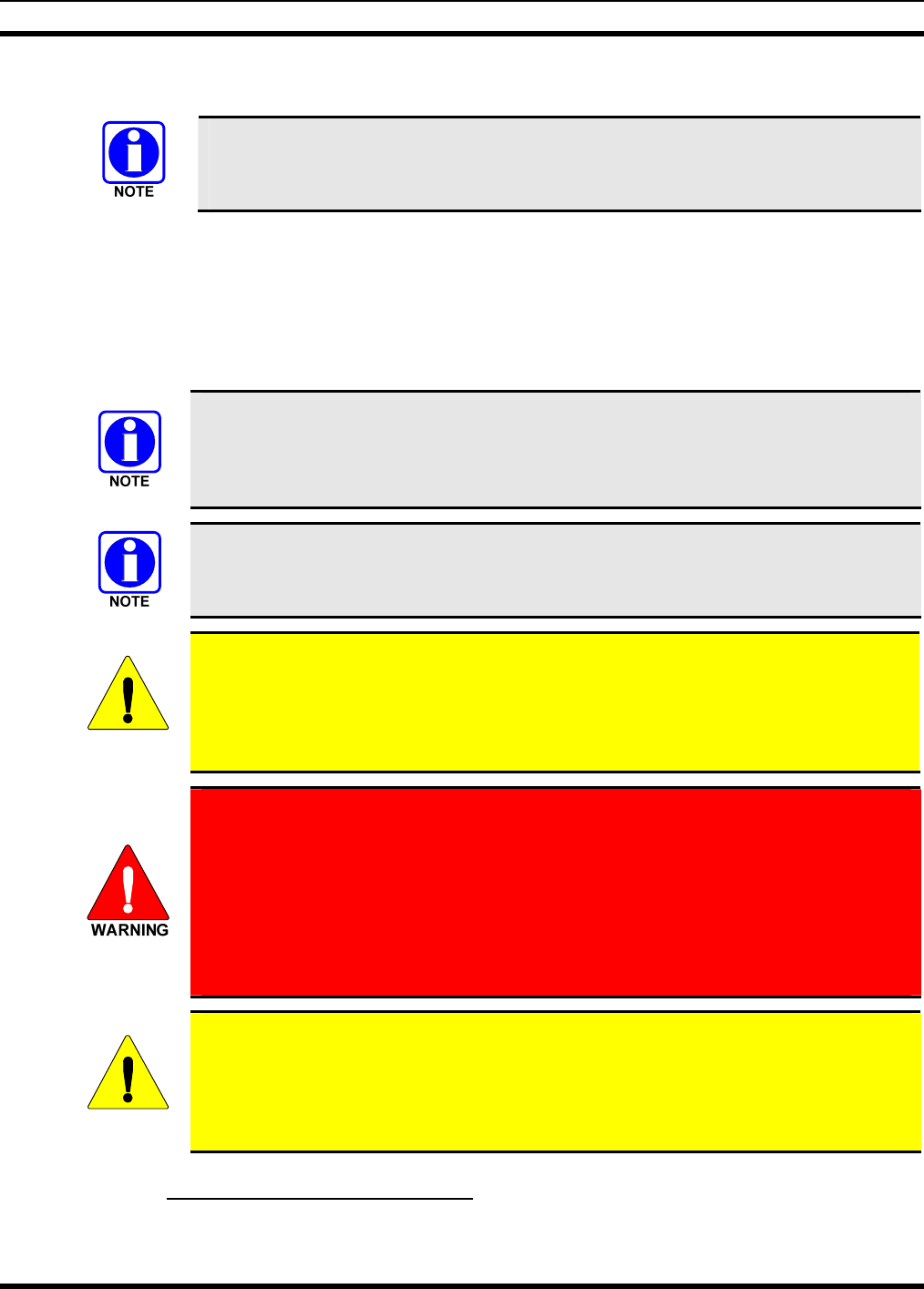
MM-014763-001
36
8 REMOTE-MOUNT RADIO INSTALLATION
This section includes detailed instructions for mechanically installing and wiring a
remote-mount M7300 mobile radio. For front-mount M7300 mobile radio installation
procedures, refer to Section 7 which begins on page 29.
8.1 MOUNTING THE REMOTE-MOUNT RADIO
This section provides details on mounting a remote-mount M7300 mobile radio in the vehicle. Control
head installation procedures are included in Section 8.3 which begins on page 43.
As an assembled unit, the radio weighs approximately 8 pounds (3.63 kilograms). The preferred mounting
of the radio is on top of a firm, flat surface. Radio dimensions are shown in Figure 8-1.
Installation Kit MAMW-NZN7R (contents listed in Table 4-2 on page 18) contains the
most complete set of materials for installing the remote-mount M7300 mobile radio.
Therefore, the following instructions make repeated reference to this kit. Item numbers
given in parenthesis refer to items in the kit.
Prior to beginning the installation, verify the radio has the proper version of software
and verify it has been configured properly for customer usage. Consult with the radio
system network administration personnel as necessary.
CAUTION
Though generally mounted in a trunk or remote location, the remote-mount mobile
radio must be kept away from heat sources. Mounting it in a location which is out of
direct sunlight is recommended but not required. Adequate ventilation space must be
provided to the rear and side fins. The radio reduces its RF output power when its
ambient temperature exceeds approximately +140 o Fahrenheit (+60o Celsius).
At a minimum, the mounting surface should be 16-guage (approximately 1/16-inch
thick) steel sheet metal. Mounting to plastic or other material with low tensile and
shear strength could lead to an unsafe and/or failed mounting condition, turning
the radio and its mounting bracket into a projectile during a high-shock incident
such as a motor vehicle accident. If the selected mounting surface does not meet
the minimum 16-guage steel sheet metal requirement, the surface should be
reinforced with a metal backing plate (not supplied) or it should be reinforced
using some other approved mounting method.
CAUTION
Before drilling holes and/or installing mounting screws, verify these operations will not
damage or interfere with any existing vehicle component (the fuel tank, a fuel line, the
transmission housing, existing vehicle wiring, etc.). Always check to see how far the
mounting screws will extend below the mounting surface prior to installation. Always
deburr drilled holes before installing screws.
8.1.1 Mounting Bracket Installation
The remote-mount radio’s mounting bracket is included with the Remote-Mount Mounting Bracket Kit
KT23117. Kit contents are shown in Figure 8-2. This kit is Item 1 listed in Table 4-2 (page 18).
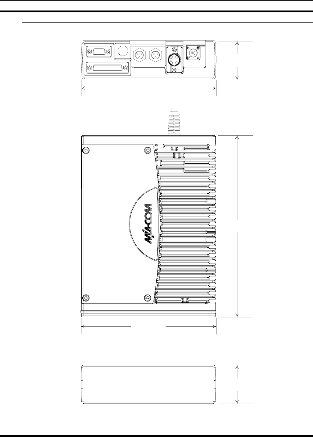
MM-014763-001
37
REAR VIEW
TOP VIEW
6.9 inches
(175 mm)
9.2 inches
(234 mm)
2.0 inches
(51 mm)
2.0 inches
(51 mm)
FRONT VIEW
6.9 inches
(175 mm)
(Partial View of
DC Power Cable)
Figure 8-1: Remote-Mount Radio Dimensions
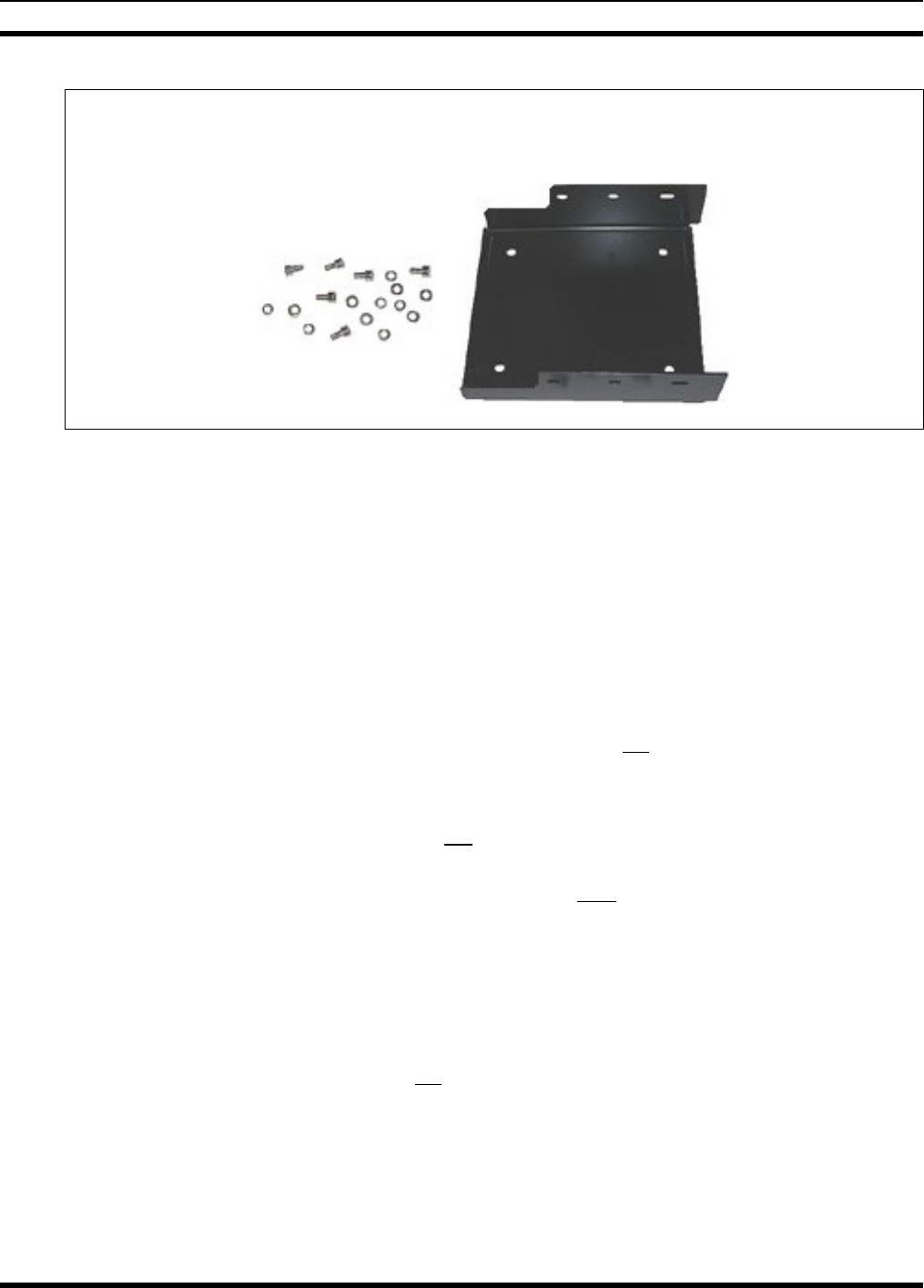
MM-014763-001
38
Mounting Bracket
M5 Hardware for FM103111V1
Securing Radio to Bracket
Figure 8-2: Remote-Mount Mounting Bracket Kit KT23117
Typically, the radio’s mounting bracket is mounted in the vehicle’s trunk, on the top surface of the trunk
tray or the trunk floor. However, it can be suspended from the trunk’s rear deck if the surface is
completely flat and the thickness of deck’s sheet metal is adequate.
When selecting a mounting location for the radio, verify sufficient clearance can be maintained around
the radio for installation and service access. A minimum clearance of 4 inches (approximately
10 centimeters) is recommended at the rear, left and right sides of the radio, and at least 2 inches
(approximately 5 centimeters) of clearance is recommended at the front of the radio.
As illustrated in Figure 8-3, the bracket is left-to-right symmetrical and the shortest portion of its side
rails are at the rear.
As all installations differ, bracket-to-vehicle mounting screws are not included. Utilization of ¼-inch-
diameter, 28-thread-per-inch (¼-28) stainless-steel self-locking hardware (i.e., machine screws with
washers and locking nuts) is highly recommended. However, ¼-inch stainless-steel self-drilling screws
may be employed to speed installation time. Self-drilling screws such as “TEK” screws do not require
drilling of a pilot hole prior to installation. Do not use common self-threading sheet metal screws because
they will loosen over time with vehicle vibrations.
The bracket has four (4) available mounting holes. All four must be used to secure the bracket to its
mounting surface.
The following mounting procedure is recommended:
1. Using the mounting bracket as a template, and/or the dimensional information shown in Figure 8-3,
mark and drill four (4) mounting holes into the mounting surface as required per the type of hardware
used. When the radio is installed in the bracket, it will extend approximately one (1) inch past the
front edge bracket, and at the rear, it will extend approximately ½-inch past the rear edge of the
bracket. This distance at the rear does not include space required for cable connections at the rear of
the radio. As previously stated, a clearance of least 4 inches (approximately 10 centimeters) at the
rear of the radio is recommended.
2. Temporarily remove the bracket and deburr all of the newly drilled holes.
3. If necessary, apply an approved paint or rust-inhibitor at the holes in the mounting surface.
4. Set the bracket back into place, and verify front-to-rear orientation.
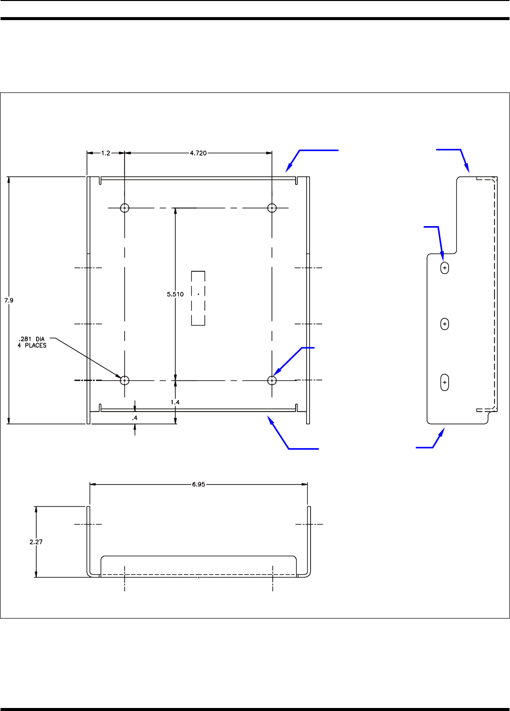
MM-014763-001
39
5. Install and tighten the mounting screws/hardware.
6. Verify the bracket is firmly secured to the mounting surface. A secure mount prevents unreasonable
vibration, which could damage the radio and/or cause its cable connections to loosen.
TOP VIEW SIDE VIEW
(Dimensions in Inches)
FRONT VIEW
(Dimensions in Inches)
(Made From FM103111 Rev. B)
Figure 8-3: Mounting Bracket FM103111V1 Dimensions
[for Remote-Mount M7300 Mobile Radio (Radio Not Shown)]
Bracket-To-
V
ehicle
Screw Holes
(4 places)
Bracket-To-Radio
Screw Holes
(6 places,
3 each side)
Rear of Bracket
Front of Bracket
MM-014763-001
40
8.1.2 Inserting the Radio into the Mounting Bracket
The radio should now be inserted into the bracket according to this procedure:
1. Lay the radio down into the mounting bracket with the front of the radio at the front of the mounting
bracket.
2. Attach the radio into the mounting bracket using the six (6) Torx® drive M5 x 10 mm stainless-steel
socket-head screws, and flatwashers and lockwashers included with the Mounting Bracket Kit (item 1
in Table 4-2). Tighten all six screws using a 4-millimeter hex key wrench until each lockwasher is
fully compressed and the radio is firm and flush in between the brackets.
3. Check the mounting area for proper clearance for cable service looping and for air circulation, plus an
area to secure and rest the excess cable lengths.
Proper mounting is one factor that ensures optimal radio performance. An improperly
mounted radio may experience degradation in the quality of voice and data
communications.
8.2 REMOTE-MOUNT RADIO’S DC POWER INSTALLATION
8.2.1 Overview of On/Off Power Wiring Configurations
Radio on/off power control is accomplished by the control head, except in the case of a data-only radio
installation which has no control head. In a standard installation, when the control head is turned on, it
“wakes-up” the radio via data activity on the CAN link. The following power wiring configurations are
supported:
• Radio turns on and off automatically with vehicle’s ignition switch/key — This configuration
allows the on/off state of the vehicle’s ignition switch/key to control the on/off power state of the
radio. The white wire of the control head’s DC Power Cable is connected to a fused switched power
source, typically identified as vehicle “Accessory” power. This source must switch on (up to positive
(+) battery voltage potential) when the vehicle’s ignition switch/key turns on, and it must switch off
(to near zero volts) when the ignition switch/key turns off. The required fuse rating is 3 amperes.
When using this configuration, the CH-721 control head’s on/off/volume control must be left in the
on position for automatic power-up/down to function properly.
In a remote-mount radio installation, to fuse the white wire of the control head’s DC
Power Cable, a waterproof (HFB type) fuse holder and a 3-amp AGC fuse are included
with the cable.
• Radio turns on and off with a manual switch — This configuration is used when, for example, the
radio must remain on even when the ignition key must be removed from the vehicle and a separate
on/off switch is acceptable. The white wire of the control head’s DC Power Cable is connected to one
side of a manually-controlled switch, and the other side of this switch is connected to unswitched and
fused vehicle power. The required fuse rating is 3 amperes. When using this configuration, the
CH-721 control head’s on/off/volume control must be left in the on position for automatic power-
up/down to function properly.
• Radio turns on with control head’s on/off/volume control (“hot wired”) — This configuration
allows radio on/off power control only via the control head’s on/off/volume control. It may be desired
if, for example, the radio must remain on even when the ignition key must be removed from the
vehicle and a separate on/off switch is not desired and/or not acceptable. The white wire of the
MM-014763-001
41
control head’s DC Power Cable must be connected to unswitched and fused vehicle power. The
required fuse rating is 3 amperes.
In all of the above cases, both the radio’s main DC power input (red wire) and the control head’s main
DC power input (also a red wire) must each be connected through an in-line fuse to unswitched vehicle
DC power. The red wire of the radio’s DC Power Cable must be connected to raw battery power (positive
battery terminal) via the supplied fuse. Likewise, the red wire of the control head’s DC Power Cable must
also be connected to unswitched vehicle DC power via another supplied fuse. The white ignition wire of
the radio’s DC Power Cable is only used for the data-only radio (i.e., no control head), and it is the only
means for turning its power on in the data-only radio installation.
8.2.2 DC Power Cable and Main Fuse Holder Installation
The radio’s DC Power Cable has a 3-pin connector, a 20-foot red wire (for the main power connection), a
20-foot white wire (only connected in a data-only radio installation), and a 4-foot black wire (for the
ground connection). It is supplied with waterproof fuse holders, two AGC-type fuses, and non-insulated
ring terminals. The following installation procedures are recommended:
8.2.2.1 Black Wire Connection (Ground Wire)
1. Connect the radio’s DC Power Cable to the radio by mating its 3-pin connector to the radio’s 3-pin
power cable connector as follows: Visually align the key and firmly push and turn the outer locking
ring clockwise until it stops. A click will be sensed to confirm proper mating.
CAUTION
Do not confuse the radio’s DC Power Cable which has a 10-AWG red wire with the
control head’s DC Power Cable which has a 12-AWG red wire. The radio requires
much more DC operating current than the control head. Therefore, it requires the
larger wire size of 10-AWG. The part number of the radio’s DC Power Cable is
CA-012365-001.
2. Prepare to connect the cable’s black wire to vehicle ground by locating an area of vehicle metal
within approximately two (2) feet of the radio. This surface must have a solid and stable connection
to vehicle ground. If not, add grounding strap(s) as necessary.
3. Strip the area of any paint or dirt to expose a bare metal surface, approximately ¾-inch square.
4. Drill a hole in the approximate center of the bare metal surface, and deburr it. A ⅜-inch non-
insulated ring terminal is supplied with the cable to make this ground connection. Therefore, hole
diameter should be appropriate for the utilized grounding screw/bolt size and type used to connect the
ring terminal to the bare metal surface. This hardware is not supplied.
5. Cut the black wire to the required length plus some additional length for a service loop, then strip
insulation back approximately ¼-inch.
6. Crimp a ⅜-inch non-insulated ring terminal (supplied with the cable) to the end of the black wire.
7. Attach the ring terminal and black wire to the bare metal surface using stainless-steel self-locking
hardware (i.e., machine screws with washers and locking nuts) or other appropriate hardware to
ensure a reliable terminal-to-metal contact. Tighten securely.
8. Apply an approved paint or rust-inhibitor over the remaining exposed bare metal surface and around
the ring terminal.
MM-014763-001
42
8.2.2.2 Red Wire and Main Fuse Holder Connection (Radio’s Main Power Wire)
1. Continue installation of the radio’s DC Power Cable by routing its 20-foot 10-AWG red wire to the
location of the vehicle’s battery (or its main DC bus bar or stud). Remove interior panels, door kick
panels, etc., and route the wire through existing channels in the vehicle body as necessary. Protect the
wire from possible chafing where necessary. Tie and stow the wire as necessary.
CAUTION
Plan the routing of the 10-AWG red wire carefully, using an existing access hole in the
vehicle’s firewall if possible. Alternately, drill a new hole approximately 3/8-inch in
diameter and install a small rubber grommet to protect the wire from chafing on the
hole’s sharp metal edge. To prevent fumes from entering the passenger
compartment, this hole/grommet/wire combination must also be sealed with a
silicon-based sealer before completing the installation.
CAUTION
Do not install any wiring or fuse holder over or in the near vicinity of the vehicle’s
engine. Excessive engine heat can cause permanent damage to these components and
can lead to intermittent electrical connection to the battery.
Before making connections to the battery’s positive post, carefully disconnect the
battery’s negative (ground) cable(s). This will prevent tools or other metallic
objects which come in contact with the battery’s positive terminal from shorting to
vehicle ground, causing sparks or even a fire or an explosion! When disconnecting
the negative cable(s), cover/insulate the positive post(s) if it is not already so a tool
cannot short between the posts. Some vehicles, such as those with diesel engines
have more than one battery; in this case, disconnect the negative cables at all
batteries.
Radio and control head fuses should not be installed until all wiring is complete.
This will prevent the radio from powering up prematurely and/or causing an in-
rush of current that could lead to shorting of the battery, sparks, or even fire.
2. Obtain one of the waterproof (HFB type) fuse holders included with the DC Power Cable.
3. Observe and follow the previously presented WARNING!
4. Cut the red wire to the required length for connection to the battery’s positive (+) battery terminal (or
the main DC bus bar or stud).
5. Prepare to splice the waterproof fuse holder into the red wire by cutting it again, at approximately
three (3) to six (6) inches from the end.
6. Strip all three (3) wire ends back approximately ⅜-inch, place a fuse holder shell on each wire, and
securely crimp a fuse holder terminal to each wire end. Before crimping, verify fuse holder shells are
oriented in the correct directions (i.e., with each large end towards the wire end).
7. Label this fuse holder and red wire appropriately (e.g., “M7300 Main Power: 15-AMP FUSE”).
8. Do NOT install a fuse into the fuse holder at this time.
9. Crimp an appropriate electrical terminal to the short red wire. A corrosion-resistant ⅜-inch ring
terminal is included with the cable for this purpose, but another size corrosion-resistant terminal type
(not supplied) may be used if required.
MM-014763-001
43
10. Connect the ring terminal directly to the battery’s positive post (or if present, to a stud on the battery’s
main/non-switched power distribution terminal block).
Most M7300 radio installations have one or more control heads connected to the radio. In
an installation of this type, the white wire of the radio’s DC Power Cable requires no
electrical connection. Rather than be cut from the cable, it is recommended that it be
routed up to the vehicle’s fuse box, coiled, labeled, and stowed for possible future use.
The white wire of the control head’s DC Power Cable is the radio installation’s ignition
sense input for on/off power control of both the control head and radio. Radio on/off
power control is accomplished by the control head. The control head “wakes-up” the radio
via data activity on the CAN link.
8.2.2.3 White Wire Connection (for Data-Only Radio Installations)
In the case of a data-only radio installation (i.e., no control head connected to the radio), the white wire of
the radio’s DC Power Cable is used as the radio installation’s ignition sense input. Therefore, it requires
electrical connection to a fused switched power source. The following procedure is recommended:
1. Route the 20-foot white wire of the radio’s DC Power Cable to the location of the vehicle’s switched
power source connection point, typically identified as “Accessory” power. Remove interior panels,
door kick panels, etc., and route the wire through existing channels in the vehicle body as necessary.
Protect the wire from possible chafing where necessary. Tie and stow the wire as necessary.
2. Connect this white wire through a fuse to the switched power source in accordance with the
instructions presented within the respective subsection of Section 8.3.4.2 (page 50) for the control
head’s white wire. Follow the procedure in Section 8.3.4.2.1 (page 50) if the vehicle’s ignition
switch/key must control the data-only radio’s on/off power. Follow the procedure in Section 8.3.4.2.2
(page 51) if a manually-controlled switch must control the data-only radio’s on/off power.
The “hot wired” wiring configuration (as depicted in Section 8.3.4.2.3) cannot be utilized
for the data-only radio, since this configuration does not employ the DC Power Cable’s
white wire.
CAUTION
When servicing the radio and/or control head, always manually power-down the radio
equipment via the control head’s on/off/volume control knob, and then remove the main
power fuse near the battery.
8.3 CONTROL HEAD INSTALLATION
8.3.1 General Information
The remote-mount M7300 mobile radio must be connected to a control head to provide the operator-to-
radio interface. Two different control heads are available — the CH-721 Scan model and the CH-721
System model. See Figure 8-4 and Figure 8-5 respectively. The CH-721 Scan model control head features
three (3) large menu selection buttons. The System model control head has a 12-button keypad to allow
advanced operations without the need of a DTMF-capable microphone.
Figure 8-6 on page 45 illustrates the rear panel of the two control head models. Both models have
identical rear panels and rear panel connectors.
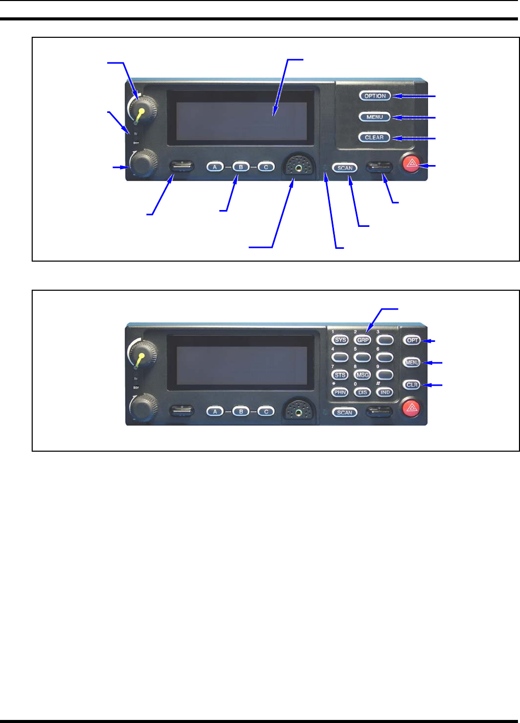
MM-014763-001
44
Figure 8-4: CH-721 Scan Model Control Head Front Panel
(Other controls are same as shown for Scan model.)
Figure 8-5: CH-721 System Model Control Head Front Panel
The CH-721 control heads feature a large easy-to-read 3-line graphical vacuum fluorescent display, an
on/off/volume control knob, menu controls and buttons, trunking mode buttons, an emergency/home
button, a scan on/off/volume control, and three (3) preset buttons. Other front panel components include a
microphone connector and LED-type indictors. One LED indicator is the busy indicator that lights when
the radio is receiving a call and one is the transmitter-enabled indicator that lights when the radio is
transmitting. The front panel also has an ambient light sensor for automatic display dimming.
3-Line Graphical Vacuum
Fluorescent Display
Microphone Connecto
r
On/Off/
Volume
Control
System/-
Group/-
Channel
Selection
Control
•/•• Ramp Control
Preset/
Softkey
Buttons
Emergency/
Home Button
+/- Ramp Control
Ambient Light-Level Sensor
Transmit
and Busy
Indicators
Scan On/Off Button
Clear Button
Menu Button
Option Button
12-Button Keypad
Clear Button
Menu Button
Option Button
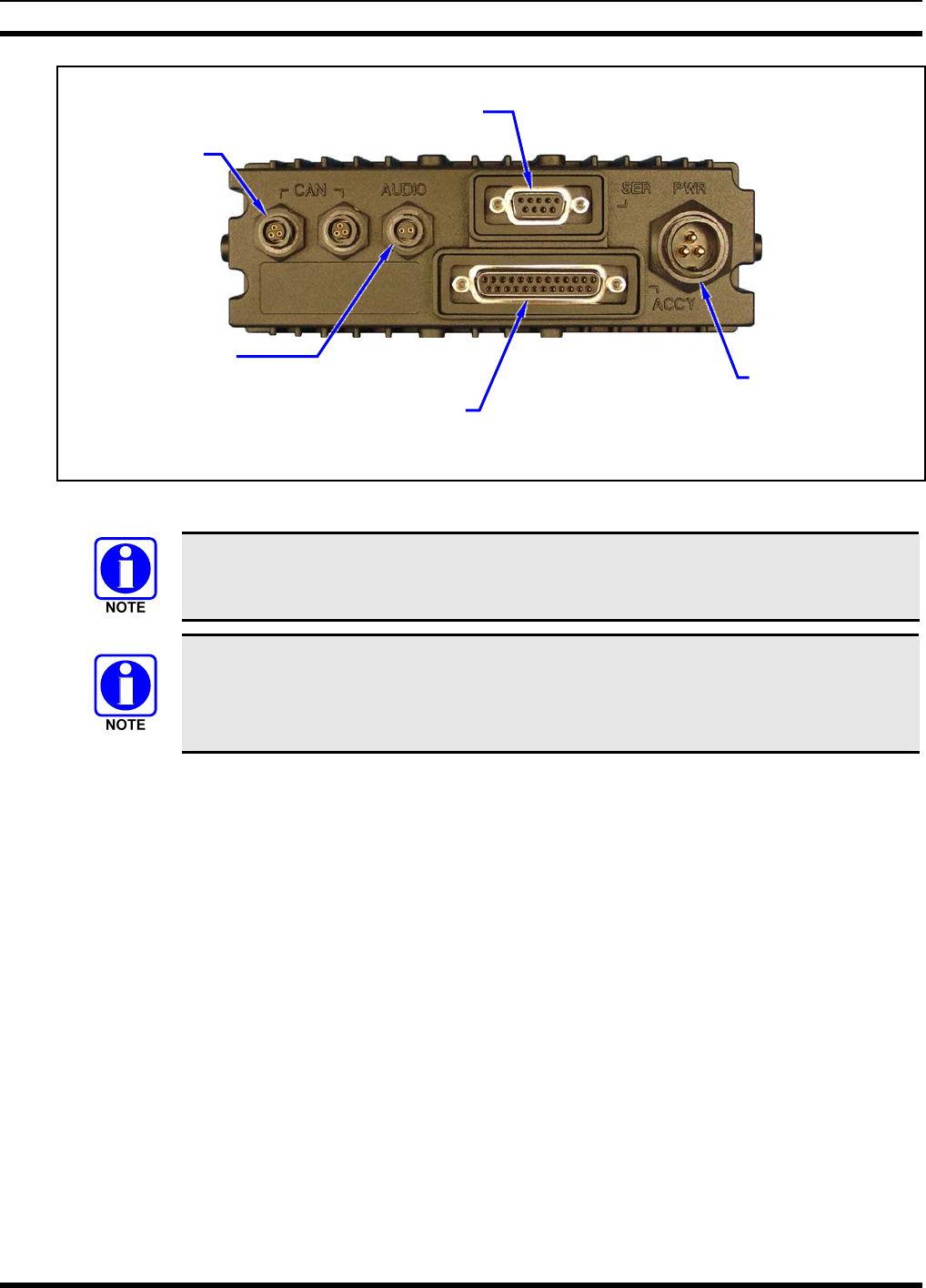
MM-014763-001
45
Figure 8-6: CH-721 Rear Panel (both control head models)
Prior to installing the control head, verify it has the proper software version installed and
verify it has been properly configured for customer use.
Because Installation Kit MAMW-NZN7R contains the most complete set of materials for
installing the radio and control head, the following instructions make repeated reference
to items within this kit. Item numbers given in parenthesis refer to items in the kit as
listed in Table 4-2 on page 18.
In a mobile installation, more than one control head can be connected to one mobile radio for multi-head
installations. A multi-head installation may be required in a vehicle such as a fire truck or any large
vehicle where more than one operator may require use of the radio. Multi-head installations also provide
other benefits such as intercom functionality between different operator positions.
CAN Port
Connectors
(2 places)
Speaker Audio
Connecto
r
Serial Port Connecto
r
(DB-9)
DC Power
Connector
Accessory Connecto
r
(DB-25) Note: Serial and Accessory connectors are
shown without waterproof covers.
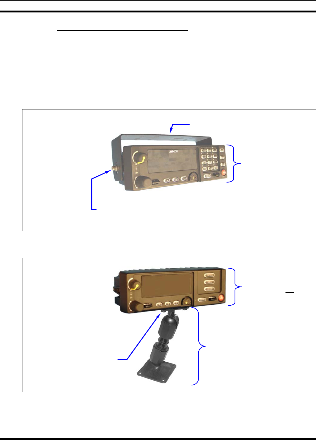
MM-014763-001
46
8.3.2 Control Head Mechanical Installation
8.3.2.1 Selecting the Mounting Location
When selecting a location for the CH-721 control head, first observe the safety and operator-convenience
related information presented in Section 5.1 on page 21. Always consider and include clearance for the
microphone’s connector that must mate to the mic connector on the front panel of the head, and clearance
for the connectors/cables that must mate to the connectors on the rear panel of the head. The CH-721
control head can be mounted under or on top of a mounting surface (typically the vehicle’s dash) as space
permits using either the standard U-shaped mounting bracket or the optional mounting pedestal.
Figure 8-7: Standard U-Shaped Control Head Mounting Bracket (Kit Part Number KT-008608)
Figure 8-8: Optional Control Head Mounting Pedestal (Part Number MACDOS0012)
Mounting Bracket (Shown
positioned above control head)
Control Head Mounting
Pedestal MACDOS0012
(Pedestal can be attached to the
bottom of the head (as shown) or it
can be attached to the top of the
head.)
Bracket shown
attached to a CH-721
System model
control head (Head is
not included with
Mounting Bracket Kit)
Pedestal shown
attached to a CH-721
Scan model control
head (Head is not
included with Mounting
Pedestal)
Socket-Head Cap (Allen) Screw, Lockwasher and Flat
Washer; 2 places each side (Included with kit)
#8-32 Pan-Head Screw; 4
places (Included with
Mounting Pedestal)
For a “hanging” control head
installation, the pedestal can
be attached to the top of the
head via threaded holes in
the top of the head’s case.
This figure shows the
pedestal attached to the
bottom of the control head via
threaded holes in the bottom
of the case.
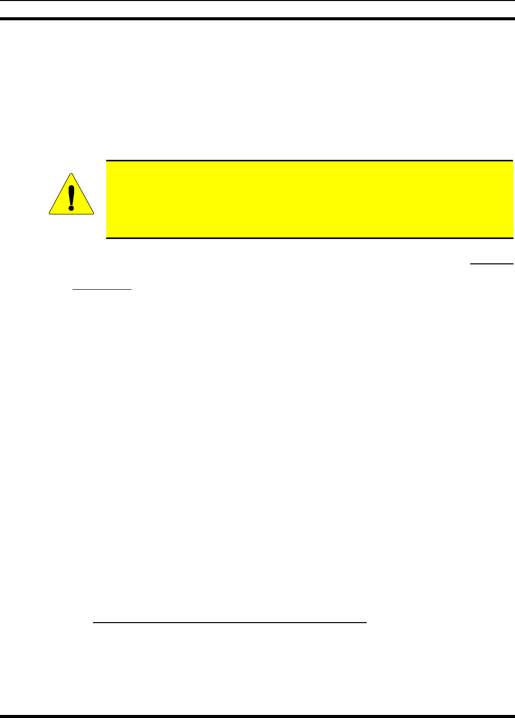
MM-014763-001
47
8.3.2.2 Using the Standard U-Shaped Mounting Bracket
If the standard U-shaped mounting bracket will be used to mount the control head, the following
mounting procedure is recommended. As listed in Table 4-2 on page 18, this bracket is item 2 in the
Installation Kit.
1. Using the mounting bracket as a template, mark and drill mounting holes into the mounting surface as
required. The round and elliptical holes in the bracket’s vehicle mounting surface are symmetrical, so
forwards/backwards positioning is not important during this step. However, positioning is important
in the next step.
CAUTION
Before drilling holes and/or installing mounting screws, verify these operations will not
damage or interfere with any existing vehicle component (the fuel tank, a fuel line, the
transmission housing, existing vehicle wiring, etc.). Always check to see how far the
mounting screws will extend below the mounting surface prior to installation. Always
deburr drilled holes before installing screws.
2. Postion the bracket at the mounting surface so the two round holes in its two side “ears” are nearest to
the normal location of the operator (typically towards the rear of the vehicle) and the two slotted holes
are furthest from the normal location of the operator (typically towards the front of the vehicle).
3. Install and tighten the mounting screws. Screws for mounting the bracket to the mounting vehicle’s
surface are not included, as all installations differ. Self-threading screws are recommended. Use of
self-drilling screws may cause damage to some mounting surfaces, such as a plastic dash panel.
4. Verify the bracket is held firmly to the mounting surface. Firm mounting prevents unreasonable
vibration, which could damage the control head and/or cause its cable connections to loosen.
5. Slide the control head into the bracket, placing the two pegs protruding from its left and right sides
into the respective round holes in the bracket’s two side “ears.”
6. In each side “ear” of the mounting bracket, start a #8-32 hex-socket-head cap (Allen) head screw with
a lockwasher and a flat washer by inserting the screw through the slotted hole in the bracket and then
into the threaded hole in the side of the control head. This hardware is included with Mounting
Bracket Kit. The lockwasher should be adjacent to the screw head and the flat washer should be
adjacent to the bracket. Turn each screw clockwise as observed from the head of the screw.
7. The control head can be positioned at various angles for best display viewing at the normal position
of the operator. As necessary, turn it on the pegs to a good position and tighten both screws using an
1/8-inch hex key (Allen) wrench until the control head is held firmly in place. Do not over-tighten.
8.3.2.3 Using the Mounting Pedestal (Optional)
An optional Mounting Pedestal, part number MACDOS0012, may be purchased separately to replace the
standard U-shaped mounting bracket. This pedestal can be attached to the bottom of the control head as
shown in Figure 8-8, and then mounted to a mounting surface below the two. It can also be attached to the
top of the head and then mounted to a mounting surface above the two.
8.3.3 Control Head-to-Radio CAN Cable Connections
8.3.3.1 General Information
A remote-mount radio installation requires a CAN cable between every two “CAN devices” and CAN
terminators on each end of the CAN link. The M7300 mobile radio is considered a CAN device, and each
CH-721 control head in the installation is also considered a CAN device. Figure 8-9 illustrates CAN cable
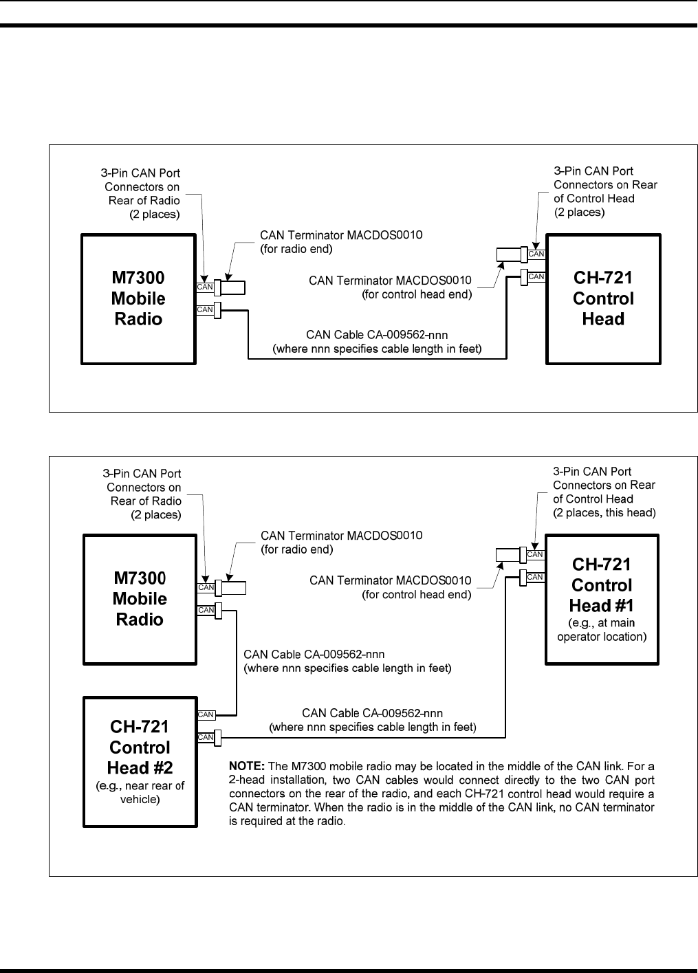
MM-014763-001
48
and CAN terminator connections for a single control head installation. Figure 8-10 illustrates this for a
multi-head control head installation where, for example, one control head is located at the main operator
location and another is located near the rear of the vehicle. Because CAN devices do not have internal
terminators, the CAN link must be terminated at both ends via external CAN terminators, as depicted in
the following figures.
For Available CAN Cable Lengths and Respective Part Numbers, see Table 4-4 on page 20.
Figure 8-9: CAN Link Connections for a Single Control Head Installation
For Available CAN Cable Lengths and Respective Part Numbers, see Table 4-4 on page 20.
Figure 8-10: Typical CAN Link Connections for a Multi-Control Head Installation
Both the radio and the control head have two CAN ports to support “daisy-chaining” of multiple control
heads or other CAN devices. Figure 5-3 on page 23 shows the radio’s two CAN port connectors, which
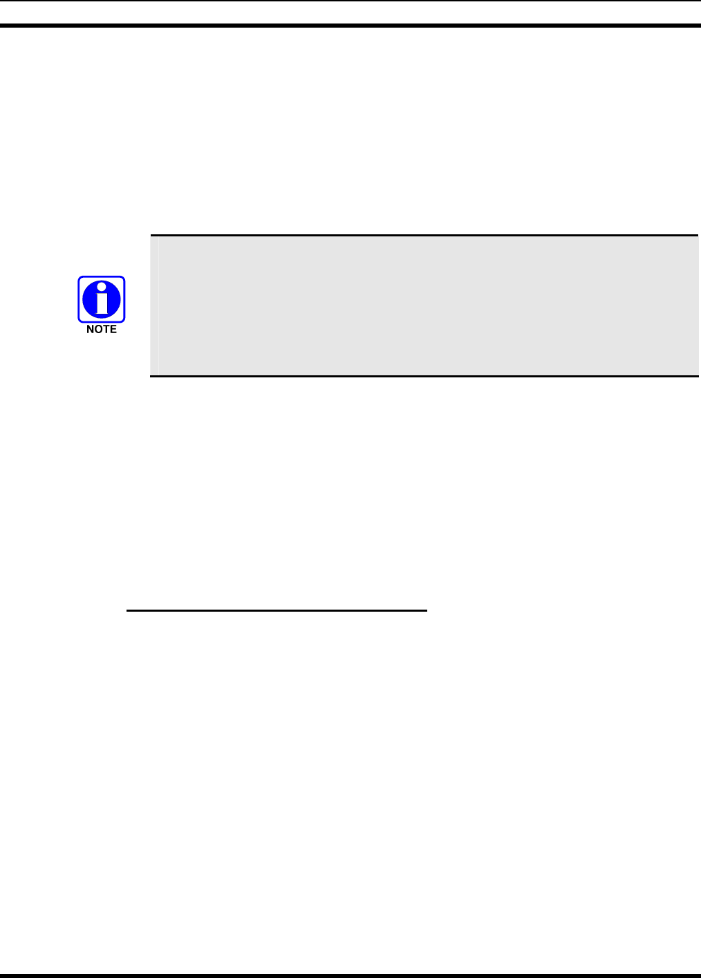
MM-014763-001
49
are located near the center of the radio’s rear panel. Figure 8-6 on page 45 shows the two CAN port
connectors on the control head’s rear panel.
8.3.3.2 Make CAN Link Terminations and Cable Connection
Follow this procedure for an installation which has only one control head. For a multi-control head
installation, refer to Figure 8-10 as necessary.
1. Mate a CAN Terminator (item 5 in Table 4-2 on page 18) onto either one of the two smaller 3-pin
CAN port connectors on the rear panel of the CH-721. This action makes the CAN termination at the
control head end of the CAN link.
When mating any CAN connection (terminators and cables) to a rear panel connector,
visually align the ¾-moon-shaped keys of the connectors, and then gently push and
turn the outer locking ring of the plug (male) connector clockwise until it stops. A mild
click will be sensed to confirm proper mating. Without visual alignment as a guide, it
is possible with excessive force to mate the CAN connectors improperly. Damage to
the connector(s) may result. Therefore, visual alignment is recommended when mating
CAN connectors.
2. Obtain a CAN Cable and mate it to the other CAN port connector on the rear panel of the CH-721.
Typically, item 6 in Table 4-2 is utilized, a 30-foot CAN cable.
3. Route the cable through the vehicle’s interior wire/cable channeling to the radio. Remove interior
panels, door kick panels, etc., as necessary. Protect the cable from possible chafing as necessary.
4. Mate this other end of the cable to one of the two CAN port connectors on the rear panel of the radio.
5. Mate another CAN Terminator to the other CAN port connector on the rear panel of the radio. This
action makes the CAN termination at the radio-end of the CAN link.
6. Loop, tie and stow the excess cable as necessary, leaving a service loop at the back of the radio and at
the back of the control head.
8.3.4 Control Head Power Cable Installation
Plan the route of the control head’s DC Power Cable carefully. Do not route the cable where it will be
damaged by heat sources or by casual contact, and protect it from wire chafe per standard installation
methods. The following procedures are recommended:
8.3.4.1 Install DC Power Cable and Make Power and Ground Connections
1. Connect the control head’s DC Power Cable (item 4 in Table 4-2 on page 18) to the large 3-pin
connector at the rear of the head. Visually align the key and gently push and turn the outer locking
ring clockwise until it stops. A click will be sensed to confirm proper mating.
2. At the back of the control head, locate a nearby section of vehicle chassis ground and strip this area of
any paint or dirt to expose a bare metal surface.
3. Cut the black wire of the control head’s DC Power Cable to the required length, plus a service loop of
at least six (6) inches, then strip it and crimp a 3/8-inch ring terminal to it. Two ring terminals of this
type are included with the cable.
4. Drill a hole as necessary and attach this ring terminal to chassis ground. Use stainless-steel self-
locking hardware (i.e., machine screws with washers and locking nuts) or other appropriate hardware
to ensure a reliable terminal-to-metal contact. Tighten securely.
MM-014763-001
50
5. At the back of the control head, tie and stow the cable as necessary.
6. For the positive 12-volt DC main power source connection, route the cable’s red wire to the location
of an unswitched 12-volt DC power source, typically near the vehicle’s battery. Remove interior
panels, door kick panels, etc. Protect the wire from possible chafing as necessary. This is the control
head’s main DC power source.
7. Obtain one of the waterproof (HFB-type) fuse holders included with the control head’s DC Power
Cable.
8. Cut excess length from the red wire and splice the fuse holder into it, near the location of the
unswitched 12-volt DC power source connection point.
9. Using an appropriate electrical terminal, connect the red wire to the unswitched DC power source. A
3/8-inch ring terminal is included with the cable for this purpose, but another terminal type (not
supplied) may be used if required.
10. Obtain the 5-amp AGC-type fuse included with the cable, and install it into the fuse holder.
Do not share the control head’s fuse with any other device. Doing so can cause excess
current to flow through the fuse, causing it to blow unnecessarily.
CAUTION
The fuse for the control head’s red wire is rated at 5 amperes. The 3-amp fuse included
with the cable must not be used for fusing the control head’s main DC power. It fuses
the head’s white wire.
8.3.4.2 Connect DC Power Cable’s White Wire
A review of the information presented in Section 8.2.1 (page 40) may be beneficial at this time. As
required per the chosen power-up configuration, connect the white wire by following one of the three
procedures presented in the respective sub-section that follows.
8.3.4.2.1 Control Head and Radio Turn on with Vehicle’s Ignition Switch/Key
With this wiring configuration, the control head and radio automatically turn on and off with the vehicle’s
ignition switch/key. The white wire of the control head’s DC Power Cable is sometimes referred to as the
“white ignition switch wire” or the “ignition sense input wire.” In this configuration, the white wire
connects to a switched power source, typically identified as “Accessory” power, that switches on and off
with the vehicle’s ignition switch/key. When using this configuration, the CH-721 control head’s
on/off/volume control must be left in the on position for automatic power-up/down to function properly.
The white ignition sense wire must be connected to a fused power source that switches
from approximately zero volts to approximately +13.6 volts when the vehicle’s ignition
switch/key is turned from the OFF position to the ACCESSORY and RUN positions.
Use of a switched power source that is subject to voltage changes as a result of other
actions, such as opening a vehicle door, may result in undesirable radio operation and/or
a degradation of radio performance.
1. Locate the vehicle’s switched ignition or “Accessory” power connection point that will be used for
the switched ignition 12-volt DC power source. This point is typically located at or near the vehicle’s
fuse panel. It may be necessary to consult the vehicle manufacturer’s wiring diagram.

MM-014763-001
51
2. Route the white wire of the control head’s DC Power Cable from the back of the head to the area near
this connection point. Protect the wire from possible chafing as necessary.
3. Obtain one of the waterproof (HFB-type) fuse holders included with the control head’s DC Power
Cable.
4. Cut excess length from the white wire and splice the fuse holder into it, near the location of the
connection point.
5. Using an appropriate electrical terminal, connect the white wire to the switched power connection
point. An open-barrel spade terminal is included with the cable for this purpose, but another type of
terminal (not supplied) may be used as required.
6. Obtain the 3-amp AGC-type fuse included with the cable, and install it into the fuse holder.
7. Tie and stow all wiring as necessary so it remains out of the way of casual contact and wire chafe is
avoided.
8.3.4.2.2 Control Head and Radio Turn On with a Manual Switch
With this wiring configuration, the control head and radio are manually turned on and off via an on/off
switch mounted separately from the control head and radio, not through the vehicle’s ignition switch/key.
This configuration is used when, for example, the radio must remain on even when the ignition key must
be removed from the vehicle and a separate on/off switch is acceptable and/or required. In this
configuration, the white wire connects to a fused switched power source such as that provided by a toggle
switch mounted on the vehicle’s dash panel. When using this configuration, the CH-721 control head’s
on/off/volume control must be left in the on position for automatic power-up/down to function properly.
1. Route the white wire of the control head’s DC Power Cable from the back of the head to an area near
the location of the panel-mounted on/off switch. Protect the wire from possible chafing as necessary.
2. Cut a short section (6 to 8 inches) off the end of the white wire and strip the ends.
3. Obtain one of the waterproof (HFB-type) fuse holders included with the control head’s DC Power
Cable, and crimp one half of it to one end of the short section of wire.
4. Using an appropriate electrical terminal, connect this short white wire to unswitched 12-volt DC
power source at or near the vehicle’s fuse box.
5. Cut another section of white wire from the cable. This wire must be long enough to reach from this
fuse holder to the location of the panel-mounted on/off switch.
6. Strip one end of this wire and crimp the other half of the waterproof fuse holder to this wire end.
7. Strip the other end of this wire and, using an appropriate electrical terminal, connect it to the common
terminal of the switch.
8. Connect the white wire of the power cable to the load (switched) side of the switch.
9. If not already, mount the switch to the vehicle’s dash panel, or other customer-selected location.
10. Obtain the 3-amp AGC-type fuse included with the cable, and install it into the fuse holder.
11. Tie and stow these wires as necessary so they remain out of the way of casual contact and wire chafe
is avoided.
12. Label this power switch accordingly. For example: “RADIO ON/OFF.”

MM-014763-001
52
8.3.4.2.3 Control Head and Radio Are “Hot Wired”
In the “hot-wired” configuration, the control head and radio are turned on and off only by the control
head’s on/off/volume control located on the front panel of the control head. In this configuration, the
control head’s white wire must be connected to unswitched and fused 12-volt vehicle power. Follow the
procedure presented in Section 8.3.4.2.1, except connect the white wire to unswitched battery power
instead of switched (“Accessory”) power.

MM-014763-001
53
9 SPEAKER INSTALLATION
9.1 FRONT-MOUNT RADIO INSTALLATION
In a front-mount radio installation, total speaker cable length (of both cables) is approximately 10 feet
(308 centimeters). Therefore, to include service loops in these cables, the speaker must be mounted within
approximately 9.5 feet (290 centimeters) of the M7300 mobile radio.
1. Select a location for the speaker that will allow for proper listening range with a moderate volume
setting.
2. Install the speaker using the hardware and mounting bracket supplied with it. For the speaker’s part
number, see Table 4-1 (page 17).
3. Route the speaker cable to the rear of the M7300 mobile radio.
4. Connect the M5300/M7300 Option Cable CA-012349-001 (item 5 in Table 4-1) to the DB-44
connector on the rear of the radio. Tighten the cable’s two (2) jackscrews securely. See Section 11.1
for additional information on this cable.
5. Mate the Option Cable’s 2-pin connector (identified P2) to the 2-pin connector on the end of the
speaker cable. A mild click will be sensed to confirm proper mating.
6. Route the cables out of the way of casual contact. Tie and stow as necessary.
9.2 REMOTE-MOUNT RADIO INSTALLATION
In a remote-mount radio installation, total speaker cable length (of both cables) is approximately five (5)
feet. Therefore, to include service loops in these cables, the speaker must be mounted within
approximately 4.5 feet of the installation’s CH-721 control head.
1. Select a location for the speaker that will allow for proper listening range with a moderate volume
setting.
2. Install the speaker using the hardware and mounting bracket supplied with it. For the speaker’s part
number, see Table 4-2 (page 18).
3. Route the speaker cable to the rear of the CH-721 control head.
4. Mate the 6-inch speaker cable (item 8 in Table 4-2) to the 2-pin connector at the rear of the control
head by visually aligning the ¾-moon-shaped keys of the connectors, and then pushing and turning
the outer locking ring of the cable connector clockwise until it stops. A mild click will be sensed to
confirm proper mating.
5. Connect the speaker cable’s 2-pin plastic connector to the respective mating connector on the 6-inch
speaker cable.
6. Route the cables out of the way of casual contact. Tie and stow as necessary.
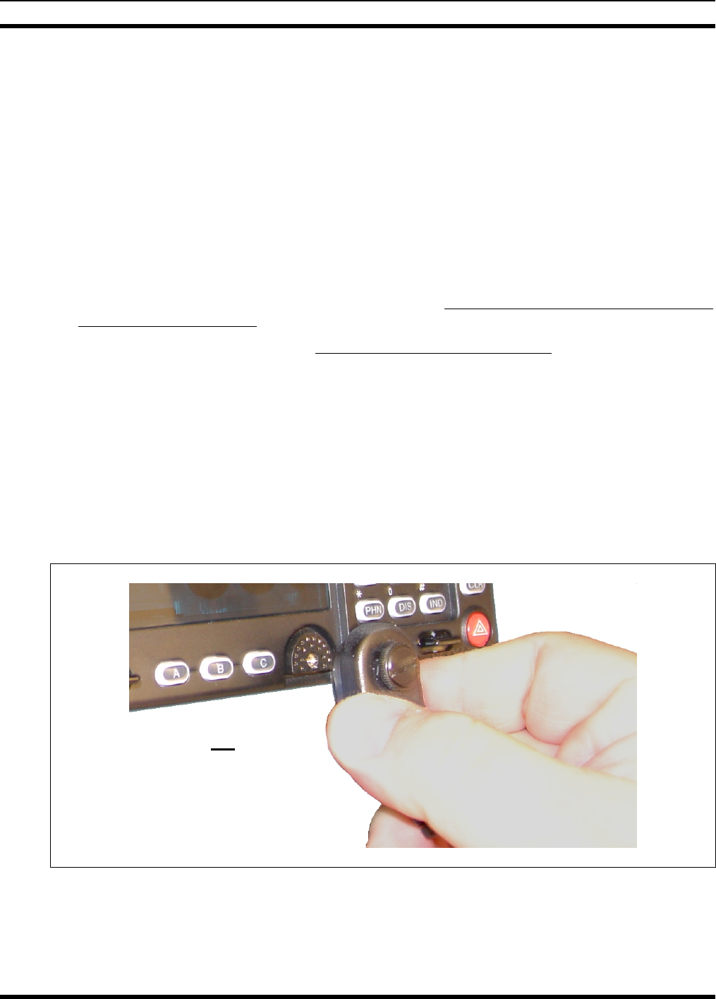
MM-014763-001
54
10 MICROPHONE ATTACHMENT
There are several versions of microphones available for use with the radio. Each has a 17-pin flush-mount
type connector that mates with the mic connector on the front panel of the control head. The mic’s
connector includes a captive thumbscrew that secures it to the mic connector on the front panel of the
control head. A microphone clip is included with each microphone. The radio can be configured to
provide a monitor function when the microphone is cradled in the clip. Connect the mic to the control
head and install the clip as follows:
1. As illustrated in Figure 10-1, grasp the mic’s connector with a thumb and index finger on the sides of
the connector just adjacent to the thumbscrew.
2. Position the connector in front of the control head’s mic connector so the mic cable’s stain relief is
hanging down and out at an approximate 45 degree angle.
3. Mate the two connectors by pressing them fully together. Do not apply any force to the thumbscrew
when mating the connectors.
4. Tighten the thumbscrew finger-tight. Do not use a screwdriver to tighten it.
5. Using the microphone clip as a template, drill mounting holes in the surface of the selected location.
6. Select a mounting surface location that has clearance for the mic when it is clipped to the clip, and
then attach the microphone clip to the surface. Use self-locking hardware (i.e., machine screws with
washers and locking nuts), self-drilling screws, or other appropriate hardware as necessary. Tighten
securely.
7. The microphone clip must be grounded to the vehicle’s chassis. If not mounted to a grounded metal
surface, complete this requirement by adding a jumper wire attached from chassis ground to the clip.
8. Clip the microphone to the clip.
Figure 10-1: Attaching the Microphone to the CH-721Control Head
As illustrated, do not apply any
force to the thumbscrew when
mating the mic connectors.
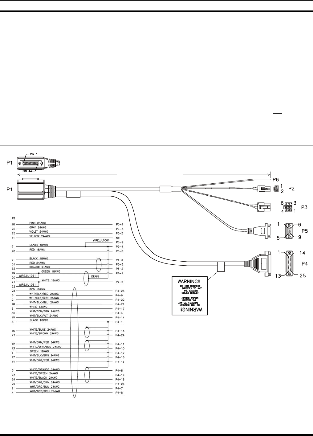
MM-014763-001
55
11 OPTIONAL CABLES
11.1 M5300/M7300 OPTION CABLE CA-012349-001
M5300/M7300 Option Cable CA-012349-001 connects to the 44-pin I/O cable connector on the rear of
the radio. It breaks out into several smaller standardized connectors, allowing straightforward access to
external I/O interfaces provided by the radio. The cable also shortens radio removal and re-installation
time when required. The cable is shown in Figure 11-1 below. The cable’s 44-pin D-subminiature
connector that mates with the connector on the rear of the radio is identified P1.
P2, the cable’s 2-pin connector, provides connections for an external speaker in a front-mount M7300
mobile radio installation. See Section 9.1 (page 53) for connection instructions. P2 is not used in a
remote-mount radio installation. In a remote-mount radio installation, the audio amplifier in the CH-721
control head drives the external speaker. In this case, the speaker connection is made at the rear of the
control head.
Approximately 66 inches
(170 centimeters)
(Pin-Out
View)
(Side View)
WIRING DIAGRAM
ASSEMBLY DIAGRAM
(Made From PS-CA-012349 Rev. -)
Figure 11-1: M5300/M7300 Option Cable CA-012349-001

MM-014763-001
56
P3, the cable’s 6-pin connector, is a connector for basics accessories (e.g., hookswitch, etc.).
P4, the cable’s D-subminiature 25-pin connector, provides audio and data connections for connections to
optional equipment such as an external siren and light system (e.g., Federal Signal SS2000 SmartSiren®).
P5, the cable’s D-subminiature 9-pin connector, provides NMEA-formatted GPS serial data connections
for the external computer processing the NMEA-formatted GPS data received by the radio’s internal GPS
receiver. See Section 12 on page 61 for additional information.
Table 11-1: M5300/M7300 Option Cable CA-012349-001 Interconnections
44-PIN I/O
CABLE
CONNECTOR
P1 PIN
SIGNAL NAME TO/FROM DESCRIPTION
19 SPKR1
20 SPKR1
P2 pin 1 Speaker Audio Output 1
(Not used in a remote-mount radio installation)
21 SPKR2
22 SPKR2
P2 pin 2 Speaker Audio Output 2
(Not used in a remote-mount radio installation)
10 OUT2 P3 pin 1 Digital Output 2 (open-collector)
7 GND P3 pins 2 & 4 Chassis Ground
(fused on radio’s PK Board at 3.15 amps)
26 HKSW P3 pin 3 Hookswitch Digital Input.
Active = Ground. Inactive = Open
25 INP2 P3 pin 5 Digital Input 2
28 SWA+ P3 pin 6 Switched A+ (DC Power) Output
8 GND P4 pin 1 Chassis ground (fused on PK Board at 3-amps)
30 DGPS_DATA P4 pin 4 GPS Serial Data
4 EXTRX P4 pin 5 External Rx Audio Output (for non-CAN based radio)
9 EXTMOD P4 pin 7 External Tx Audio Input (for non-CAN based radio)
3 SDATA P4 pin 8
In a front-mount M5300/M7300 radio installation, this pin
for the siren/PA interface is the siren serial data output
(open-collector/open-drain) from the radio’s mounted
(local) CH-721. It serially transfers siren and light control
data from the head/radio to a connected third-party siren
and light system (e.g., Federal Signal SS2000
SmartSiren®). Data rate = 1200 bps. For a remote-mount
radio installation, see footnote 2.
5 FDISC P4 pin 9 Buffered Discriminator Audio
13 ALO P4 pin 10 Audio Ground/Reference
(fused on radio’s PK Board at 3.15 amps)
12 MICHI P4 pin 11 In a front-mount M5300/M7300 radio installation, these
two pins provide the public address (PA) mic audio from
2 In a remote-mount M5300/M7300 mobile radio installation, this pin on the radio’s DB-44 connector should not be used. It
is not functional. Instead, the respective pin on the CH-721 Option Cable’s female DB-25 pin connector. See Section 11.3
for additional information.

MM-014763-001
57
Table 11-1: M5300/M7300 Option Cable CA-012349-001 Interconnections
44-PIN I/O
CABLE
CONNECTOR
P1 PIN
SIGNAL NAME TO/FROM DESCRIPTION
1 EXTALO P4 pin 12
the mounted (local) CH-721 to the siren and light system
(e.g., Federal Signal SS2000 SmartSiren®). For a
remote-mount radio installation, see footnote 2.
14 VOLHI P4 pin 13 Volume High
15 CTLON P4 pin 14 Control On Digital Output (for non-CAN based radio)
16 XTONEENC P4 pin 15 External Tone Encode Audio (for non-CAN based radio)
17 XTONEDEC P4 pin 16 External Tone Decode Audio (for non-CAN based radio)
6 EXTALO P4 pin 17 External Audio Output (Balanced, Low; for non-CAN
based radio)
24 HORNRING P4 pin 18
In a front-mount M5300/M7300 radio installation, this pin
for the siren/PA interface is the horn/ring logic input to the
radio’s mounted (local) CH-721. When a connected third-
party siren and light system (e.g., Federal Signal
SmartSiren® SS2000) has its horn/ring function active,
this input is used to signal the head/radio as such. For a
remote-mount radio installation, see footnote 2.
23 SONOFF P4 pin 19
In a front-mount M5300/M7300 radio installation, this pin
for the siren/PA interface is the siren on/off logic output
(open-collector) from the radio’s mounted (local) CH-721.
It is the signal that powers the connected third-party siren
and light system (e.g., Federal Signal SmartSiren®
SS2000) on and off. For a remote-mount radio
installation, see footnote 2.
18 INP1 P4 pin 21 Digital Input 1 (for non-CAN based radio)
2 OUT1 P4 pin 22 Digital Output 1 (open-collector; for non-CAN based
radio)
29 TXENB+ P4 pin 23 Transmit Enable B+ (for non-CAN based radio)
27 EXTMIC P4 pin 24 External Mic Audio Input
28 SWA+ P4 pin 25 Switched A+ DC Power Output
(for non-CAN based radio)
32 GPS_NMEA_RX P5 pin 2 Serial Rx Input for GPS NMEA-Formatted Serial Data
31 GPS_NMEA_TX P5 pin 3 Serial Tx Output for GPS NMEA-Formatted Serial Data
7 GND P5 pin 5 Ground for GPS Serial Data Signals
(fused on radio’s PK Board at 3.15 amps)
11 IGNITION (no connection) Unused/Spare ignition sense input.
33
through
44 — (no connections) These pins of P1 are not used/not connected.
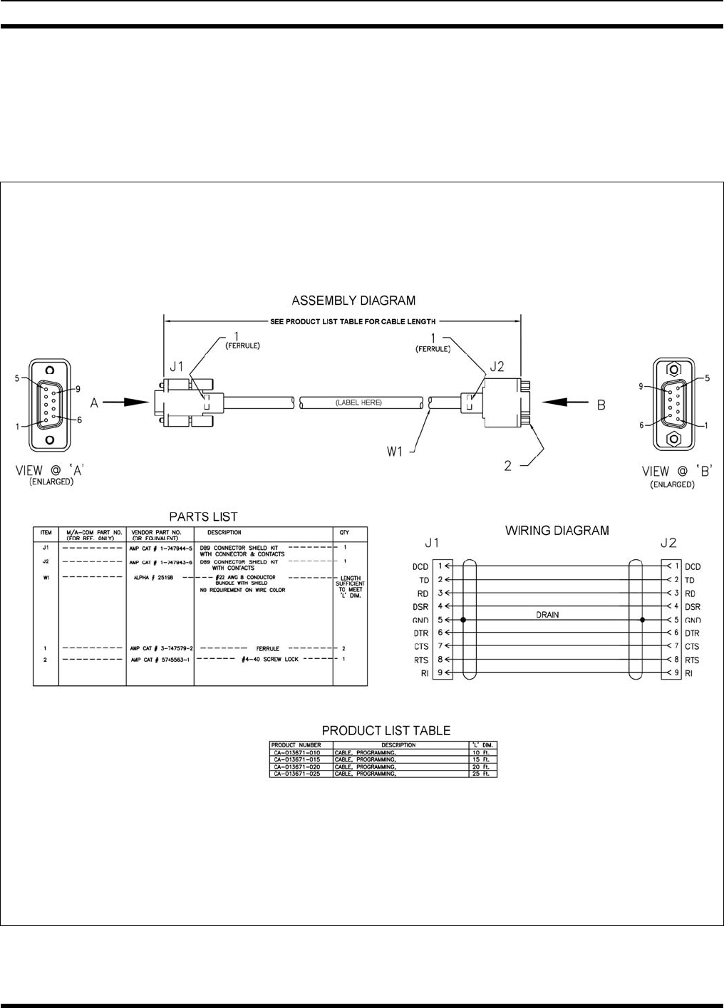
MM-014763-001
58
11.2 SERIAL PROGRAMMING CABLE CA-013671
Serial Programming Cable CA-013671-010 (10 feet long) and CA-013671-020 (20 feet long) can be used
to program and configure the M7300 mobile radio via a Personal Computer. This cable has a female
DB-9 connector on one end for connection to the PC’s serial port and a male DB-9 connector on the other
end for connection to the serial port on the rear of the radio. The cable’s assembly and wiring diagrams
are shown in Figure 11-2 below.
(Made From PS-CA-013671 Rev. -)
Figure 11-2: Programming Cables CA-013671-010 and -020
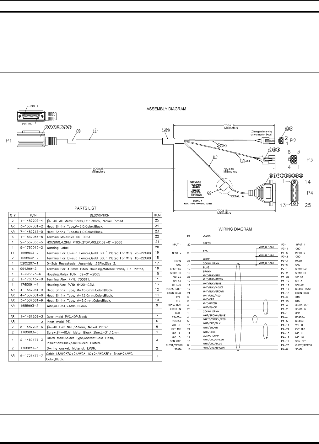
MM-014763-001
59
11.3 CH-721 OPTION CABLE CA-011854-001
CH-721 Option Cable CA-011854-001 can be used to connect optional equipment to the 25-pin
D-subminiature (DB-25) connector on the rear of the CH721. This cable expands the connections
available at the 25-pin connector to three (3) separate connectors. The cable’s assembly and wiring
diagrams are shown in Figure 11-3 below.
(Made From PS-CA-011854 Rev. D)
Figure 11-3: CH-721 Option Cable CA-011854-001
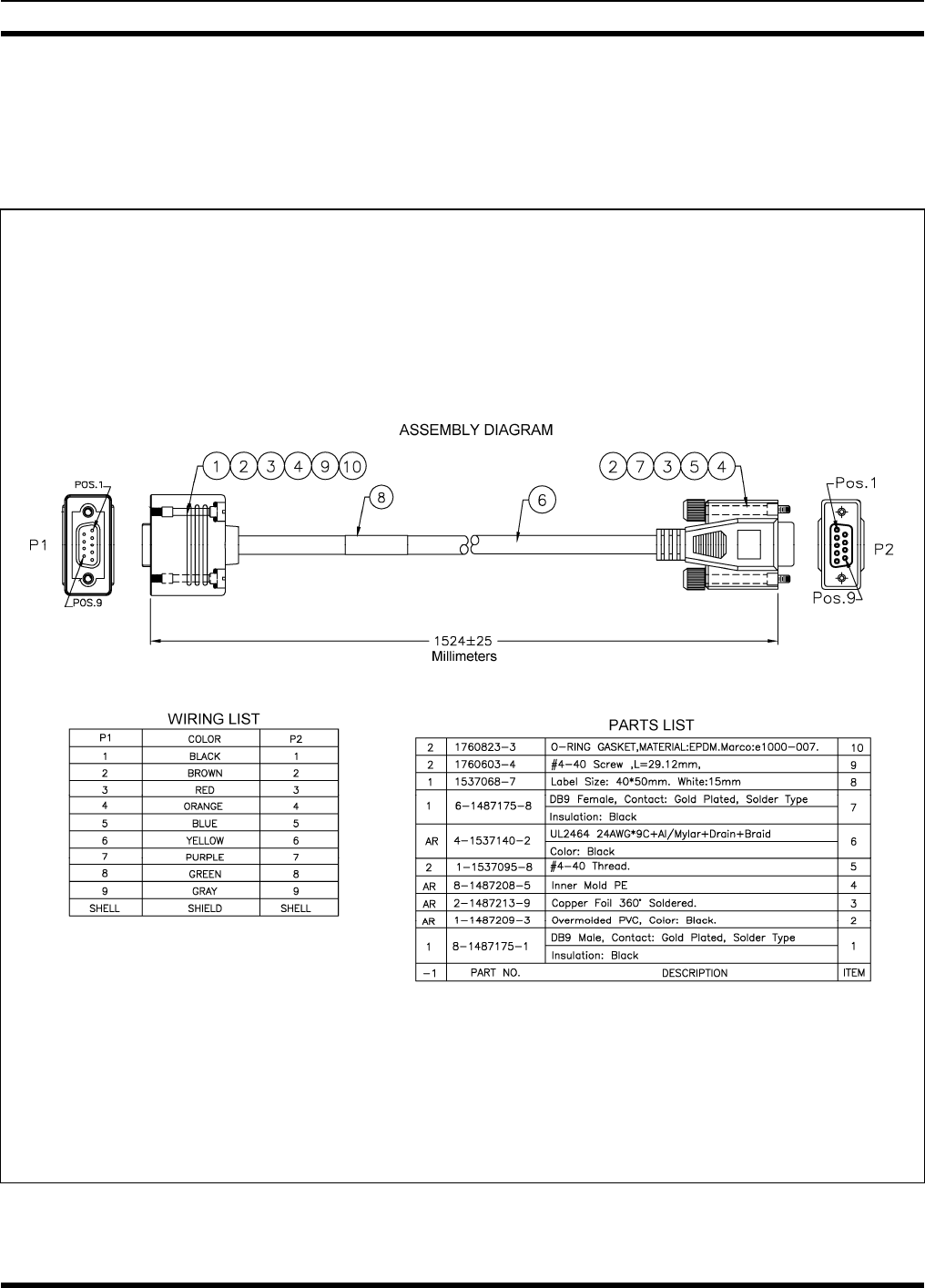
MM-014763-001
60
11.4 CH-721 SERIAL PROGRAMMING CABLE CA-104861
Serial Programming Cable CA-104861 (5 feet) can be used to program and configure the CH-721 control
head via a Personal Computer. This cable has a female DB-9 connector on one end for connection to the
PC’s serial port and a male DB-9 connector on the other end for connection to the serial port on the rear
of the head. The cable’s assembly and wiring diagrams are shown in Figure 11-4 below.
(Made From PS-CA-104861 Rev. A)
Figure 11-4: Programming Cable CA-104861
MM-014763-001
61
12 GPS NMEA-FORMATTED SERIAL DATA
CONNECTION
To obtain GPS NMEA-formatted serial data from the radio, use of the M5300/M7300 Option Cable
CA-012349-001 is required. Follow this procedure to complete the GPS NMEA-formatted serial data
connections:
1. Obtain M5300/M7300 Option Cable CA-012349-001. Each “leg” of this cable is approximately
65 inches long (166 centimeters).
2. Connect the cable’s 44-pin D-subminiature (DB-44) male connector to the DB-44 female connector
on the rear panel of the radio. Tighten the two jackscrews with a small flathead screwdriver. Do not
over-tighten.
3. Connect the cable’s DB-9 female connector to the computer’s serial port DB-9 male connector —
either directly or with an optional MAMROS0055 serial cable — and tighten the screws until firm.
Route the cabling as required.
4. Follow the manufacturer’s instructions on processing the NMEA-formatted GPS data from the radio.
If the M5300/M7300 Option Cable is not available, a 3-wire serial cable can be field-
fabricated. On the radio end, this cable must interface to the three GPS-related signals of
the radio’s 44-pin I/O Cable connector (pins 7, 31 and 32). See Table 11-1 for additional
information.
Industry software to process GPS information through this interface is not supported by
M/A-COM.
MM-014763-001
62
13 INITIAL POWER-UP TEST
1. At the radio’s main waterproof (HFB-type) fuse holder installed near the vehicle battery, insert the
15-amp AGC-type fuse that was included with the radio’s DC Power Cable.
2. Tie and stow all fuse holders at this location to prevent excess vibration/movement.
3. Carefully reconnect the vehicle’s battery ground cable.
4. If not already, temporarily connect the mobile antenna cable from the vehicle-mounted 900 MHz
antenna to the female TNC RF connector on the rear panel of the radio. This is a temporary
connection until test procedures in Section 14 are complete.
5. If the radio is equipped with the GPS receiver option, permanently connect the antenna cable from the
GPS antenna (or mobile/GPS combo antenna) to the female SMA connector on the rear panel of the
radio. The male SMA connector on most GPS antenna cables has a 5/16-inch hex collar, so the use of
a wrench of this same size is normally required for tightening. However, some may have collars with
only knurled surfaces, so a standard wrench or torque wrench cannot be used. In either case, do not
over tighten the connector and do not twist the cable when tightening.
6. If the installation is wired so the vehicle’s ignition key/switch turns the radio on and off, turn the
switch to the Accessory or Run position.
7. If the control head is not already powered up, do so by rotating its on/off/volume control clockwise
out of the detent position.
8. Verify the control head has powered-up by observing its display. If the display is not lit, refer to
Section 8.2.1 as necessary.
Unlike many mobile radio products, the radio powers-up to the state of last control.
As long as the software configuration parameters have been loaded, successful installation is almost
immediately realized:
• After a short boot-up sequence, the control head displays login information and/or a talk group.
• If no errors are displayed, the installation is most-likely properly wired.
• If an error is displayed, recheck all cable connections, verify all fuses are properly installed, and
verify battery power on the load side of the fuses, etc. If problems persist, contact M/A-COM’s
Technical Assistance Center (see page 16).
• Consult the Operator’s Manual for operational information.
Refer to the following section for performance test information.
MM-014763-001
63
14 PERFORMANCE TESTS
This section includes procedures to verify the performance of the installation’s mobile antenna system.
There are three (3) procedures in this section:
• Changing Operating Mode for Tests
• Testing by Transmitting into a Dummy Load (a 50-Ohm RF Terminator)
• Testing by Transmitting into the Mobile Antenna
CAUTION
The accuracy of test results depends upon a DC power source in the range of 13.8 to
16 volts DC, with a current capacity of greater than 8 amps. Make sure the vehicle’s
battery is fully charged by running the engine for a few minutes before the test, and
keep the engine running during the test procedures. Abide by the following
WARNING!
If the vehicle’s engine must remain running, the vehicle location should be well
ventilated so exhaust fumes from the engine do not cause harm!
CAUTION
If a vehicle equipped with this radio requires jump-starting, the radio installation’s
main AGC fuse (15-amp) should be removed from the holder prior to jump-starting.
Doing so will prevent damage to the radio system.
Prior to installation, the radio’s power level should be configured appropriately. The
wide range of power levels indicated in the following procedures takes into account
such things as: customer’s requirements; measurement errors, especially to include
uncalibrated equipment; cabling losses; and voltage and temperature variations. By no
means should the result from Performance Testing in this section be construed as the
exact value of power level output from the radio, as the value is set and more
accurately measured in the factory. The values obtained in these test procedures
determine a successful installation only.
14.1 CHANGING OPERATING MODE FOR TESTS
To complete tests in this section, placing the radio in a conventional mode and using an average-
responding wattmeter to measure RF transmit power is recommended. However, if the radio is not
programmed for conventional mode operations (i.e., OTP mode is available but ECP mode is not), tests
will require a peak-reading RF wattmeter to measure RF transmit power. To select either conventional or
OpenSky mode, use one of the following procedures:
14.1.1 Changing from OpenSky to Conventional
1. If necessary, apply power to the radio and turn it on.
2. Use the control head’s •/•• Ramp Control to scroll through the menu until Mode Menu appears in
the middle line of the display. This control is shown in Figure 8-4 and in Figure 8-5 on page 44.
3. Use the +/- Ramp Control to select an available conventional channel/system.
MM-014763-001
64
4. Confirm the selection by pressing the MENU button, then toggling the Ramp Control once (to
select Y for Yes), followed by pressing the MENU button again. The radio will enter the selected
mode as indicated by the display.
5. Select a conventional channel for test transmissions using either the •/•• Ramp Control or the
System/Group/Channel Selection Control (required control per programming).
14.1.2 Changing from Conventional to OpenSky
1. If necessary, apply power to the radio and turn it on.
2. Use the control head’s •/•• Ramp Control to scroll through the menu until an OpenSky system’s
name is displayed.
3. After a few seconds, the radio will automatically transition to OTP mode for operations on the
selected OpenSky system.
4. If the radio is not programmed for auto-login, login to the OpenSky system. For login instructions,
refer to the Operator’s Manual (publication MM-014716-001) or the respective Quick-Guide
(publication MM-014368-001) as necessary. The Quick-Guide is included with the radio when it
shipped from the factory.
5. Select a talk group for test transmissions using either the •/•• Ramp Control or the System/-
Group/Channel Selection Control (required control per programming).
14.2 REQUIRED TEST EQUIPMENT
Table 14-1: Required Test Equipment
TEST EQUIPMENT MODEL / PART NUMBER & DESCRIPTION
Average-Responding
Wattmeter
(for conv. measurements)
Bird Electronic Corp. Model 43 (or equivalent) with Type N female
connectors at input and output ports.
Peak-Reading
Wattmeter
(for OpenSky measurements)
Bird Electronic Corp. Model 4314B (or equivalent) with Type N female
connectors at input and output ports.
Wattmeter
Slug Bird Electronic Corp. Element 25E, 25 watts, 400 - 1000 MHz (or
equivalent).
RF Coaxial
Jumper Cable
Pasternack Enterprises PE3661-36 (or equivalent) 50-Ohm Coaxial Cable
with TNC male connector and Type N male connector, approximately three
(3) feet in length. The utilized cable must have VSWR below 1.5:1 within
the RF passband.
N-to-TNC
RF Adapter
Pasternack Enterprises PE9090 (or equivalent) Type N male to TNC female
adapter. Required to connect the cable of the vehicle-mounted
700/800 MHz antenna to the wattmeter.
50-Ohm RF Terminator
(“Dummy Load”) Pasternack Enterprises PE6106 (or equivalent) 50-ohm RF terminator rated
at greater than 50 watts power, with Type N male connector.
Vehicle-Mounted
Antenna Tests are performed with the vehicle-mounted 700/800 MHz antenna per
the installation described in Section 6 of this manual.
or
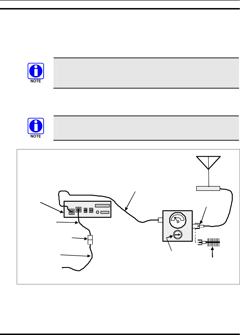
MM-014763-001
65
14.3 TRANSMITTING INTO A DUMMY LOAD
1. Using the Type N male to TNC male RF coaxial jumper cable, connect the radio’s antenna connector
to the wattmeter’s input connector. Refer to Figure 14-1 as necessary.
2. Connect the 50-ohm dummy load to the wattmeter’s output connector, in place of the antenna cable
from the vehicle-mounted 700/800 MHz antenna.
As previously stated, if conventional mode is not available per radio programming
(i.e., OTP mode is available but ECP mode is not), a peak-reading RF wattmeter is
required to measure RF transmit power. Otherwise, the use of an average-responding
wattmeter is recommended. Recommended wattmeter types are listed in Table 14-1.
3. If not already, turn the radio on and set it to the required operating mode (based upon available radio
programming and test equipment). Refer to Section 14.1 as necessary.
4. Set the radio to a test talk group or conventional channel, if available.
It is recommended that a test talk group/channel be allocated for this testing. This
same group should be used during the antenna test procedure which is presented in the
subsequent section.
Wattmeter
Type N-to-TNC
RF Ada ptor
TNC Male-to-Type N Female
Coaxial Jumper Cable
Slug
(25 W, 400–
1000 MHz) Dummy
Load
V
ehicle-Mounted
700/800 MHz
Antenna
IN
OUT
M7300
Mobile Radio
(Rear View)
Radio’s DC
Power Cable
Installation’s DC
Power Cable
From 13.8-Volt
Fused Power Source
3
-Pin
Connectors
NOTE: CAN cable
connections not indicated.
Figure 14-1: Wattmeter Connections for Antenna System Tests
5. Position the wattmeter’s slug to measure forward RF output power. Rotate it if necessary. The arrow
on the face of the slug must point away from the radio and towards the dummy load for forward
power measurements.
MM-014763-001
66
6. For conventional mode transmissions, set the wattmeter to measure average RF power.
For OpenSky mode transmissions, set the wattmeter to measure peak RF power.
7. Key the radio’s transmitter via the microphone’s PTT button.
8. For an OpenSky mode transmission, compare the wattmeter’s reading with the target RF output
power range of between 11.8 and 18.9 watts (15 watts ±1 dB). This transmit output power range
assumes the radio is currently configured for high-power transmit.
For a conventional mode transmission, compare the wattmeter’s read with the target RF output power
range of between 27.7 and 44.2 watts (35 watts ±1 dB). This transmit output power range assumes
the radio is currently configured for the high-power transmit.
Transmit only for as long as needed to take the measurement, then immediately
disable the transmission.
9. If the wattmeter reading is within the range, record the measured value in the appropriate space on
the data collection form near the end of this manual.
If the wattmeter reading is outside the range, verify the radio’s power supply voltage (i.e., battery
voltage) is within the specified range, recheck all connections and measure the RF output power
again. If this fails to produce a reading within the range, replace it and repeat this procedure. If
problems persist, contact M/A-COM’s Technical Assistance Center (see page 16).
14.4 TRANSMITTING INTO THE MOBILE ANTENNA
1. Connect the antenna cable from the vehicle-mounted 700/800 MHz antenna to the wattmeter as
shown in Figure 14-1.
2. If not already, turn the radio on and set it to the required operating mode (based upon available radio
programming and test equipment). Refer to Section 14.1 as necessary.
3. Set the radio to a test talk group or conventional channel, if available.
It is recommended that a test talk group/channel be allocated for this testing.
Otherwise, interference with other radio users in the system may occur. Also, during
transmissions, always observe the RF exposure-related safety information
presented in Section 1.2 (begins on page 6).
4. Position the wattmeter’s slug to measure forward RF output power. Rotate it if necessary. The arrow
on the face of the slug must point away from the radio and towards the antenna for forward power
measurements.
5. For conventional mode transmissions, set the wattmeter to measure average RF power.
For OpenSky mode transmissions, set the wattmeter to measure peak RF power.
6. Key the radio’s transmitter via the microphone’s PTT button.
7. For an OpenSky mode transmission, compare the wattmeter’s reading with the target RF output
power range of between 11.8 and 18.9 watts (15 watts ±1 dB). This transmit output power range
assumes the radio is currently configured for high-power transmit.
For a conventional mode transmission, compare the wattmeter’s read with the target RF output power
range of between 27.7 and 44.2 watts (35 watts ±1 dB). This transmit output power range assumes
the radio is currently configured for the high-power transmit.
MM-014763-001
67
Transmit only for as long as needed to take the measurement, then immediately
disable the transmission.
8. If the wattmeter reading is within the range, record the value in the appropriate space on the data
collection form near the end of this manual.
If the wattmeter reading is outside the range, verify the radio’s power supply voltage (i.e., battery
voltage) is within the specified range, recheck all connections, and measure the forward power again.
If these checks/corrections fail to produce a reading within the range, check all cabling and
connections and repeat the testing procedure to this point. In the event the wattmeter reading still falls
outside the range, replace the antenna, make sure all connections are seated firmly, and repeat the
testing procedure. If problems persist, contact M/A-COM’s Technical Assistance Center (see page
16).
9. Position the wattmeter’s slug to measure reverse (reflected) RF power from the antenna. The arrow
on the face of the slug must point away from the antenna and to the radio to measure reverse power.
10. Key the radio’s transmitter via the microphone’s PTT button.
11. Compare the wattmeter reading with the RF power output range of 2 watts or less.
Transmit only for as long as needed to take the measurement, then immediately disable
the transmission.
12. If the wattmeter reading is within the range, record the value in the appropriate space on the data
collection form near the end of this manual.
If the wattmeter reading is outside the range, make sure the antenna is consistent with the specified
frequency range of the radio. Recheck all antenna connections, and measure the reverse power again.
If the installation employs a ¼-wave unity-gain antenna, observe the NOTE that follows step 8. If
these checks/corrections fail to produce a reading within the range, replace the antenna and repeat the
entire antenna test procedure. Any value exceeding the maximum allowable reflected power value
will result in a diminished RF output signal. If problems persist, contact M/A-COM’s Technical
Assistance Center (see page 16).
13. Disconnect the coaxial cable jumper and wattmeter.
14. Permanently connect the cable from the vehicle-mounted 700/800 MHz antenna to the radio’s
antenna cable by mating the two TNC connectors together. Use two pairs of soft-jaw pliers to gently
tighten this connection. Do not over tighten and do not twist either cable.
15. Make several test calls on the radio system to verify operation of the mobile radio. Before making the
calls, select other talk groups or conventional channels, as required to verify operation.
To prevent RF leakage and ensure peak performance, make sure the RF connectors are
tight, but do not over-tighten so connector damage will not occur.
Improper installation of the RF cables may lead not only to poor radio
performance but also to harmful exposure to RF electromagnetic energy.

MM-014763-001
68
Testing is complete. The radio is now ready for normal communications.
MM-014763-001
69
14.5 TEST PERFORMANCE DATA FORM
Enter the information requested on this data collection form. Clip this form and file it as a permanent record of
the tested performance of the M7300 mobile radio installation.
Clip
Here
Company Performing Installation Technician Performing Test
Date of Test
(mm/dd/yyyy)
Mobile Radio Serial Number Antenna Make and Model Numbers
Power into a Dummy
Load
Watts
Forward Power with
Antenna Reflected Power
with Antenna
Watts
Watts

MM-014763-001
70
15 COMPLETE THE INSTALLATION
Double-check the following items before considering the installation completed:
• Verify all newly installed mechanical hardware is mounted securely and all respective mounting
hardware is tight.
• Verify all electrical interconnections are connected properly and the associated connector attachment
hardware is tight. Pay special attention to all RF antenna cables!
• Verify all related fuses are correctly installed and properly rated.
• Verify all electrical cables and wiring are tied, stowed, and protected so they are out of the way of
casual contact, away from sources of extreme heat, and wire chafing cannot occur. Pay special
attention to all RF antenna cables!
• To prevent fumes from entering the vehicle’s passenger compartment, seal the hole/grommet/wire
combination at the firewall with a silicon-based sealer.
• Verify all vehicle components are properly reinstalled such as kick panels, headliners, and seats.
• If the installation includes a separately-mounted on/off power switch for manually turning the radio
(and possibly others systems) on and off, verify it is labelled accordingly. For example: “Radio
ON/OFF.”
• Remove all tools and unused hardware from the vehicle.
• Verify the test performance data has been recorded on the data collection form shown in this manual.

MM-014763-001
71
16 WARRANTY
A. M/A-COM, Inc. (hereinafter "Seller") warrants to the original purchaser for use (hereinafter "Buyer")
that Equipment manufactured by or for the Seller shall be free from defects in material and
workmanship, and shall conform to its published specifications. With respect to all non-M/A-COM
Equipment, Seller gives no warranty, and only the warranty, if any, given by the manufacturer shall
apply. Rechargeable batteries are excluded from this warranty but are warranted under a separate
Rechargeable Battery Warranty (ECR-7048).
B. Seller’s obligations set forth in Paragraph C below shall apply only to failures to meet the above
warranties occurring within the following periods of time from date of sale to the Buyer and are
conditioned on Buyer’s giving written notice to Seller within thirty (30) days of such occurrence:
1. for fuses and non-rechargeable batteries, operable on arrival only.
2. for parts and accessories (except as noted in B.1) sold by Seller’s Service Parts Operation, ninety
(90) days.
3. for P7200, P7100IP, P5400, P5300, P5200, P5100, P3300, PANTHER™ 405P and 605P, M7300,
M7200 (including V-TAC), M7100IP, M7300 and M3300 radios, two (2) years, effective
10/01/2007.
4. for all other equipment of Seller’s manufacture, one (1) year.
C. If any Equipment fails to meet the foregoing warranties, Seller shall correct the failure at its option (i)
by repairing any defective or damaged part or parts thereof, (ii) by making available at Seller’s factory
any necessary repaired or replacement parts, or (iii) by replacing the failed Equipment with equivalent
new or refurbished Equipment. Any repaired or replacement part furnished hereunder shall be
warranted for the remainder of the warranty period of the Equipment in which it is installed. Where
such failure cannot be corrected by Seller’s reasonable efforts, the parties will negotiate an equitable
adjustment in price. Labor to perform warranty service will be provided at no charge during the
warranty period only for the Equipment covered under Paragraph B.3 and B.4. To be eligible for no-
charge labor, service must be performed at a M/A-COM factory, by an Authorized Service Center
(ASC) or other Servicer approved for these purposes either at its place of business during normal
business hours, for mobile or personal equipment, or at the Buyer’s location, for fixed location
equipment. Service on fixed location equipment more than thirty (30) miles from the Service Center or
other approved Servicer’s place of business will include a charge for transportation.
D. Seller’s obligations under Paragraph C shall not apply to any Equipment, or part thereof, which (i) has
been modified or otherwise altered other than pursuant to Seller’s written instructions or written
approval or, (ii) is normally consumed in operation or, (iii) has a normal life inherently shorter than the
warranty periods specified in Paragraph B, or (iv) is not properly stored, installed, used, maintained or
repaired, or, (v) has been subjected to any other kind of misuse or detrimental exposure, or has been
involved in an accident.
E. The preceding paragraphs set forth the exclusive remedies for claims based upon defects in or
nonconformity of the Equipment, whether the claim is in contract, warranty, tort (including
negligence), strict liability or otherwise, and however instituted. Upon the expiration of the warranty
period, all such liability shall terminate. The foregoing warranties are exclusive and in lieu of all other
warranties, whether oral, written, expressed, implied or statutory. NO IMPLIED OR STATUTORY
WARRANTIES OF MERCHANTABILITY OR FITNESS FOR PARTICULAR PURPOSE SHALL
APPLY. IN NO EVENT SHALL THE SELLER BE LIABLE FOR ANY INCIDENTAL,
CONSEQUENTIAL, SPECIAL, INDIRECT OR EXEMPLARY DAMAGES.
This warranty applies only within the United States.
M/A-COM, Inc. M/A-COM, Inc.
1011 Pawtucket Blvd. 221 Jefferson Ridge Parkway
Lowell, MA 01853 Lynchburg, VA 24501
1-877-OPENSKY 1-800-528-7711 ECR-7047F

Tyco Electronics Wireless Systems Segment
221 Jefferson Ridge Parkway
Lynchburg, Virginia 24501
(Outside USA, 1-434-385-2400) Toll Free 1-800-528-7711
www.macom-wireless.com Printed in U.S.A.