HARRIS TR-0051-E M7300/M5300 Mobile Radio User Manual Manual 2
HARRIS CORPORATION M7300/M5300 Mobile Radio Manual 2
HARRIS >
Contents
- 1. Manual
- 2. Manual 1
- 3. Manual 2
- 4. Manual 3
Manual 2
MM-015371-001
33
7 ANTENNA(S) INSTALLATION
7.1 MOBILE ANTENNA INSTALLATION
7.1.1 Install the Mobile Antenna
Table 4-2 (page 22) lists the mobile antenna available for M7300 mobile radio motorcycle installations.
This antenna is a voltage/end-fed high-impedance antenna that provides the proper VSWR and radiation
pattern without the use of a ground plane. Typical antenna gain without a ground plane is 0 dBd.
The following mobile antenna installation procedure is recommended:
1. Review the information presented in Section 1.2 (page 6), taking note on the Recommended
Minimum Safe Lateral Distance for Controlled Environments presented in Table 1-1 (page 8).
2. Verify the antenna’s mounting location on the triangular-shaped end of the Case/Antenna Bracket
places motorcycle operator outside of the Minimum Safe Lateral Distance for Controlled
Environments. If it does not, the bracket(s) must be repositioned on the motorcycle. If necessary,
contact M/A-COM’s Technical Assistance Center. See page 17 for TAC contact information.
3. Mount the antenna in accordance with the instructions supplied with it.
4. Calculate the required antenna coax cable length using the information presented in the following
section.
CAUTION
Since the antenna is a high-impedance, voltage/end-fed antenna, the length of the
coaxial cable from the base of the antenna to the radio’s TNC antenna connector
is critical. It cannot be an arbitrary length. To prevent possible extraneous
radiation, RFI feedback from the antenna to the radio, high VSWR, or antenna ground
currents, select an antenna coaxial cable length that is close to a multiple of an odd
quarter-wavelength. Refer to the following information for details on calculating the
correct cable length.
7.1.2 Calculating the Antenna Cable Length
Typically, an antenna coax cable length of approximately 32 inches will be required to reach from the
base of the antenna, inside the case, to the TNC RF antenna connector at the rear of the radio. This length
includes appropriately 6 inches for a service loop inside the case. To calculate the proper antenna coax
cable length, proceed as follows:
1. Determine the center frequency of the majority of programmed transmit channel frequencies.
2. Use the following formula to calculate the ¼-wavelength, in inches:
MHzinFrequency
inchesin 2805
¼=
λ
Example: Assume the customer has an M7300 radio with all transmit frequencies between 816 and
821 MHz. Therefore, the center frequency is 818.5 MHz. Applying the above formula results in:
5.818
2805
¼=inchesin
λ
= 3.43 inches
3. Calculate the ½-wavelength by multiplying the ¼-wavelength by 2:
Example: = 3.43 x 2 = 6.86 inches
MM-015371-001
4. Pick a value of N then use the following formula to calculate an antenna cable length that will result
in a cable length long enough for the installation:
(N x ½λ in inches + ¼λ in inches) x 0.66 = required cable length in inches
Example: Choose N = 7. Therefore, the cable length in inches calculates to be:
(7 x 6.86 inches + 3.43 inches) x 0.66 = 33.96 inches
5. Verify the calculated cable length is long enough to route it from the base of the antenna, into the
radio’s weather-resistant case, to the TNC RF connector on the rear of the radio, and leaving some
cable length for service loops. If not, recalculate the length per the formula in the previous step, using
a greater value of N.
6. Shorten the cable buy cutting it to the calculated length.
7.1.3 Route Cable, Crimp-On TNC RF Connector and Connect It to the Radio
1. Route the antenna coax cable from the base of the antenna to the radio’s weather-resistant case.
2. Route the cable into the case by passing it through the hole in the bottom of the case.
3. Outside the case, tie and stow the cable.
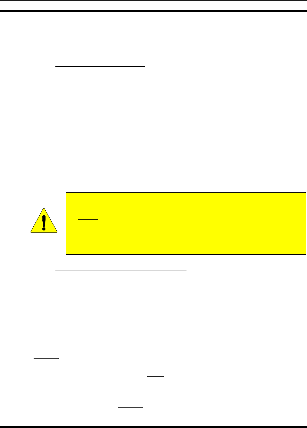
4. Using an appropriate crimp tool, crimp the supplied TNC RF connector to the end of the antenna
cable. For crimping instructions, see Figure 7-1 or the instructions supplied with antenna.
Actual Size; Dimensions are in Inches
(VS-AN-025167-010 Rev. A)
Figure 7-1: Crimping Instructions for TNC RF Connector
5. The antenna cable is connected to the radio’s TNC receptacle-type (female) RF connector per a
procedure presented later in this manual. The cable and its TNC connector must be protected from
34

MM-015371-001
damage, dirt, and/or metal shavings which may be generated during the mechanical and electrical
installation of the radio. Temporarily tying the connector and cable-end within a small plastic bag is
recommended.
To properly use a thru-line wattmeter with a high-impedance voltage/end-fed antenna,
one of the following two conditions must be met:
• If the wattmeter is located at the radio and the odd multiple of a quarter-wavelength
of coax to the antenna is used, correct readings will result. Any other length of coax
will result in improper readings.
• If a length of coax equal to a multiple of a half-wave length is installed between the
radio’s antenna port (TNC RF connector on rear panel) and the thru-line wattmeter
and an odd multiple of a quarter-wavelength of coax to the antenna is used, correct
readings will also result. Any other length of coax will result in improper readings.
7.2 GPS ANTENNA INSTALLATION
(REQUIRED ONLY FOR GPS RECEIVER OPTION)
If the M7300 mobile radio is equipped with the GPS receiver option, the GPS receiver requires
connection to an externally-mounted GPS antenna. The following antenna installation procedure is
recommended:
1. Refer to the GPS antenna manufacturer’s mounting and testing instructions for installation guidance.
Install the antenna in accordance with these instructions. As a general rule, it should be mounted on a
mechanically-secure surface where it will have an unobstructed view of the sky, down to 50% view.
If necessary, contact M/A-COM’s Technical Assistance Center. See page 17 for TAC contact
information. Do not alter the GPS antenna cable length; tie and stow excess cable as necessary.
2. Route the cable from the antenna to the radio case, and pass it through the square holes in
case/antenna bracket and in the bottom of the case. The cable must be kept out of casual contact.
Outside the case, tie and stow this cable as necessary to protect it from possible chafing. Nylon (or
equivalent) cable/wire ties should be used at least every six (6) inches.
3. Permanently connect the antenna cable from the GPS antenna (or mobile/GPS combo antenna) to the
female SMA-type RF connector on the rear panel of the radio. The male SMA-type RF connector on
most GPS antenna cables has a 5/16-inch hex collar, so the use of a wrench of this same size is
normally required for tightening. However, some may have collars with only knurled surfaces, so a
standard wrench or torque wrench cannot be used. In either case, do not over tighten the connector
and do not twist the cable when tightening.
4. Loop excess cable length inside the case and tie and stow it at one side of the radio’s mounting
bracket.
35
MM-015371-001
8 CONTROL HEAD MECHANICAL INSTALLATION
8.1 GENERAL INFORMATION
The M7300 mobile radio must be connected to a control head to provide the operator-to-radio interface.
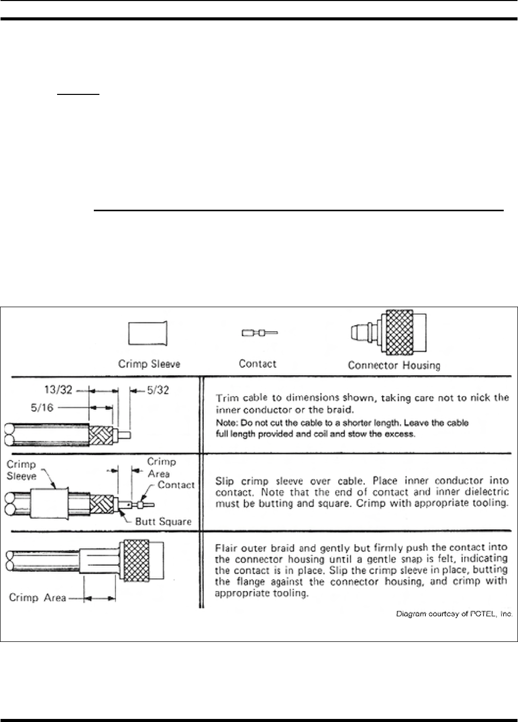
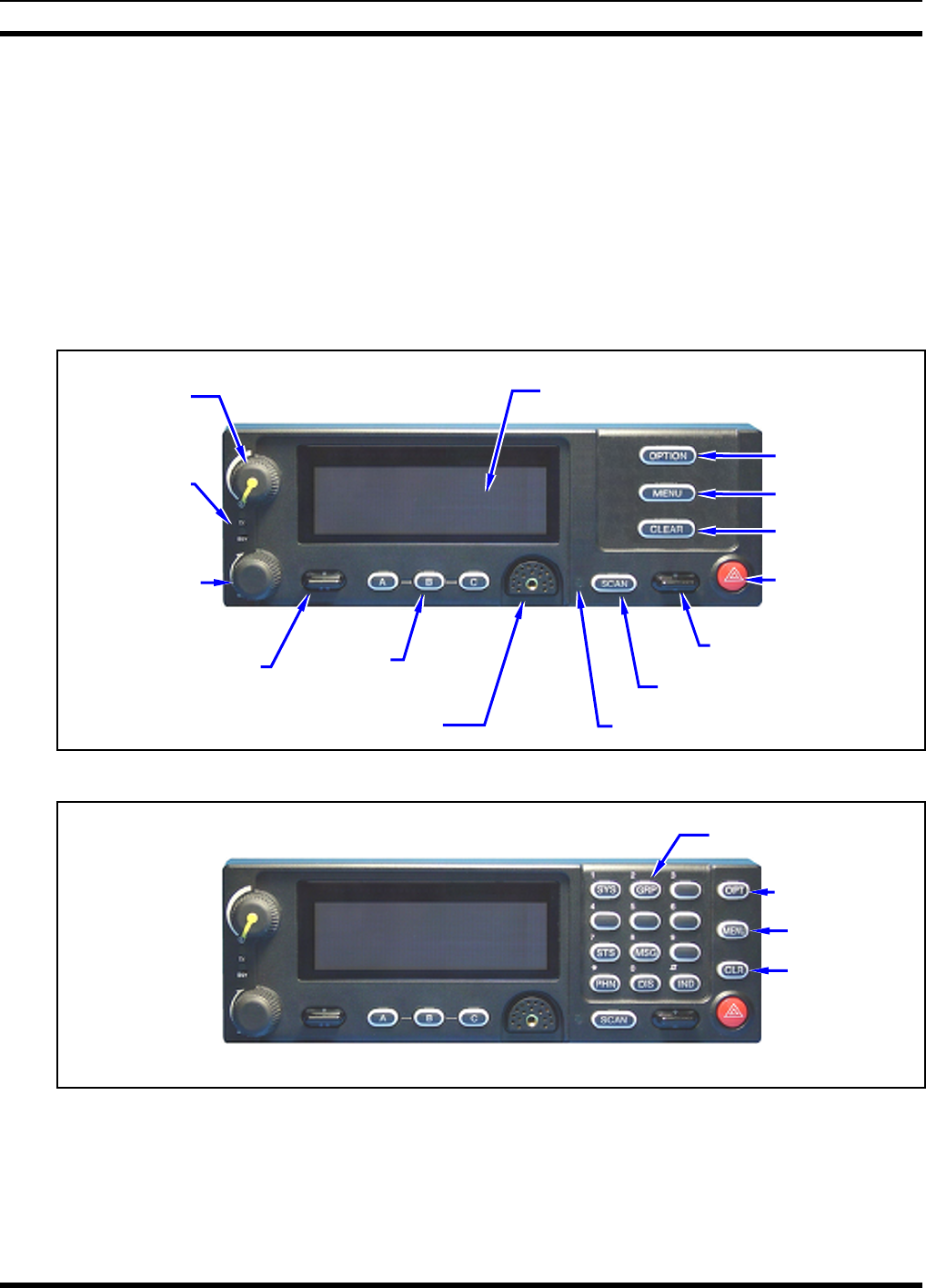
Two different control heads are available — the CH-721 Scan model and the CH-721 System model. See
Figure 8-1 and Figure 8-2 respectively. The CH-721 Scan model control head features three (3) large
menu selection buttons. The System model control head has a 12-button keypad to allow advanced
operations without the need of a DTMF-capable microphone.
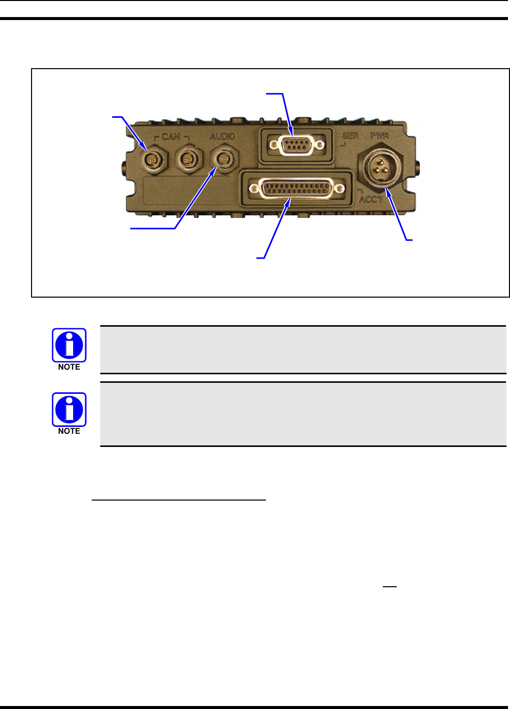
Figure 8-3 on page 37 illustrates the rear panel of the two control head models. Both models have
identical rear panels and rear panel connectors.
Transmit
and Busy
Indicators
On/Off/
Volume
Control
3-Line Graphical Vacuum
Fluorescent Display
Option Button
Menu Button
Clear Button
System/-
Group/-
Channel
Selection
Control
Emergency/
Home Button
Preset/
Softkey
Buttons
+/- Ramp Control
•/•• Ramp Control Scan On/Off Button
Microphone Connecto
r
Ambient Light-Level Sensor
Figure 8-1: CH-721 Scan Model Control Head Front Panel
(Other controls are same as shown for Scan model.)
12-Button Keypad
Option Button
Menu Button
Clear Button
Figure 8-2: CH-721 System Model Control Head Front Panel
The CH-721 control heads feature a large easy-to-read 3-line graphical vacuum fluorescent display, an
on/off/volume control knob, menu controls and buttons, trunking mode buttons, an emergency/home
button, a scan on/off/volume control, and three (3) preset buttons. Other front panel components include a
microphone connector and LED-type indictors. One LED indicator is the busy indicator that lights when
36
MM-015371-001
the radio is receiving a call and one is the transmitter-enabled indicator that lights when the radio is
transmitting. The front panel also has an ambient light sensor for automatic display dimming.
Serial Port Connecto
r
(DB-9)
CAN Port
Connectors
(2 places)
Speaker Audio
Connecto
r
DC Power
Connector
Accessory Connecto
r
(DB-25) Note: Serial and Accessory connectors are
shown without waterproof covers.
Figure 8-3: CH-721 Rear Panel (both control head models)
Prior to installing the control head, verify it has the proper software version installed and
verify it has been properly configured for customer use.
Because Installation Kit MAMW-NZN7X contains the most complete set of materials
for installing the radio and control head, the following instructions make repeated
reference to items within this kit. References to item numbers refer to items in the kit as
listed in Table 4-1 on page 20.
8.2 MOUNTING THE CONTROL HEAD
8.2.1 Selecting a Mounting Location
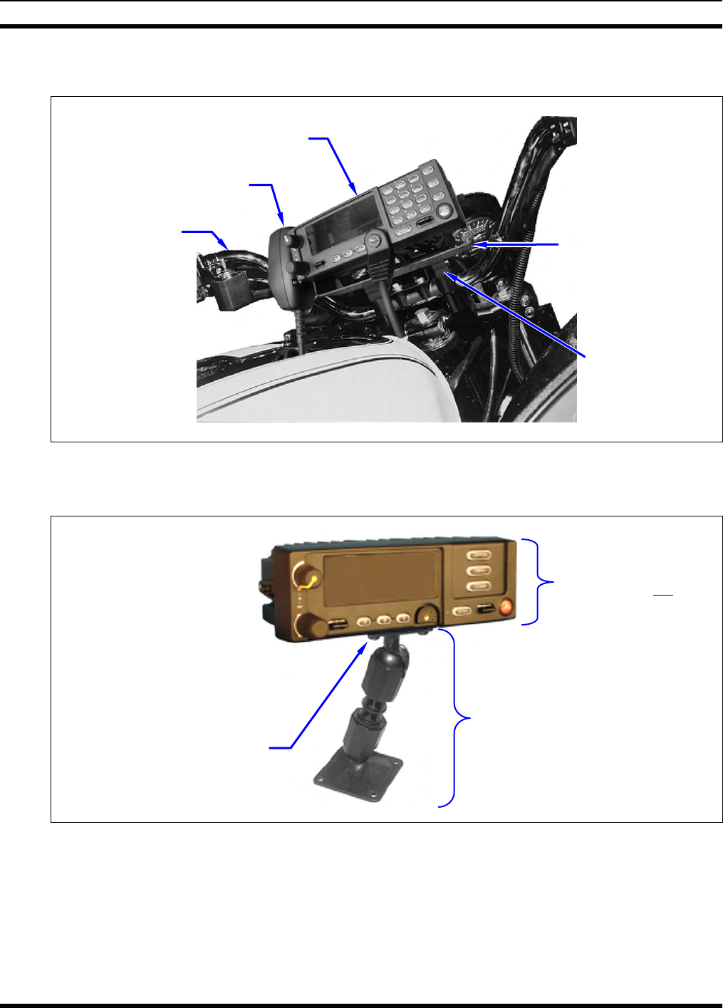
Typically, the CH-721 control head is mounted at the centerline of the motorcycle between the steering
handlebars, and secured to the handlebars or to the frame just below the handlebars. A typical installation
is shown in Figure 8-4. The CH-721 control head can be mounted using either the standard U-shaped
mounting bracket or the optional mounting pedestal. See Figure 8-4 and Figure 8-5 respectively. The
selected mounting location must:
• Be safe for the motorcycle operator (e.g., the head must located so it does not interfere with
motorcycle steering or any other motorcycle controls);
• Allow convenient access by the operator;
• Be neat;
• Include clearance for the microphone’s connector that mates to the mic connector on the front of the
head;
• Include clearance for the connectors/cables that mate to the connectors on the rear of the head; and,
37
MM-015371-001
• Have a relatively easy access for servicing.
CH-721 Control Head
Microphone Control Head
Mounting Bracket
FM24841-0001
(Included with
Mounting Bracket
Kit KT-008608)
Control Head
Adapter
Bracket
(Not Supplied)
Motorcycle’s
Left Handleba
r
(partial view)
Figure 8-4: Typical CH-721 Control Head Installation on a Motorcycle
(Using the Standard U-Shaped Mounting Bracket)
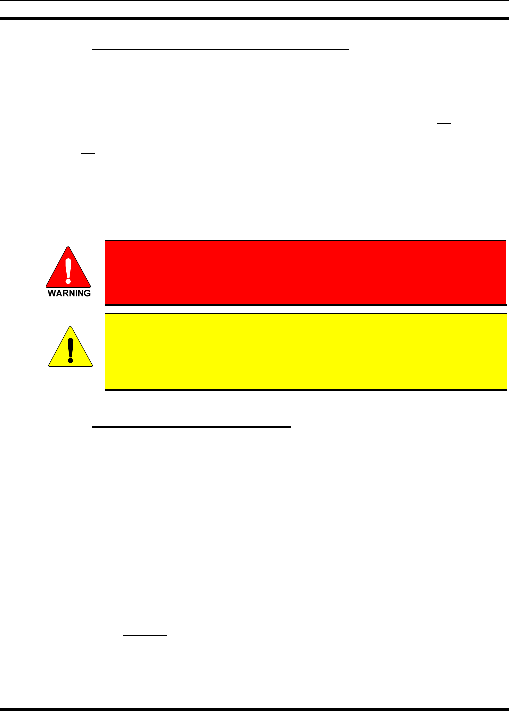
Pedestal shown
attached to a CH-721
Scan model control
head (Head is not
included with Mounting
Pedestal)
For a “hanging” control head
installation, the pedestal can
be attached to the top of the
head via threaded holes in
the top of the head’s case.
This figure shows the
pedestal attached to the
bottom of the control head via
threaded holes in the bottom
of the case.
Control Head Mounting
Pedestal MACDOS0012
(Pedestal can be attached to the
bottom of the head (as shown) or it
can be attached to the top of the
head.)
#8-32 Pan-Head Screw; 4
places (Included with
Mounting Pedestal)
Figure 8-5: Optional Control Head Mounting Pedestal (Part Number MACDOS0012)
Due to the large number of different makes and models of motorcycles, it is the installer’s responsibility
to determine how to mount the control head and other related equipment such as the microphone hanger
and speaker.
38
MM-015371-001
39
8.2.2 Control Head Adapter Bracket (Not Supplied)
In some cases, a control adapter bracket (not supplied) may be required to attach the supplied U-shaped
control head mounting bracket (or the optional mounting pedestal) to the motorcycle. Control head
adapter brackets for all makes and models are not available from the factory. Therefore, obtaining or
field-fabricating an adapter bracket will be required in some cases. All utilized bracketry:
• Must be mounted in a location that is safe for the motorcycle operator (e.g., so it does not interfere
with steering and other motorcycle controls);
• Must not interfere with the motorcycle operator’s visibility, including the view of all motorcycle
instruments;
• Provide a secure mount for the control head;
• Must utilized rounded corners/edges to the maximum extent possible; and,
• Must not be mounted in a way that compromises the strength of the motorcycle’s frame or other key
components.
Never comprise the strength of a motorcycle’s frame, handlebars, or other key
components by drilling or grinding holes in these components. Use clamps or
another method approved by the motorcycle manufacturer to attach radio
components.
CAUTION
Before drilling holes and/or installing mounting screws, verify these operations will not
damage or interfere with any existing vehicle components such as the fuel tank, a fuel
line, engine, transmission, wiring, etc. Always check to see how far the mounting
screws will extend below the mounting surface prior to installation. Always deburr
drilled holes before installing screws.
8.2.3 Mounting the CH-721 Control Head
8.2.3.1 Using the Standard U-Shaped Mounting Bracket
The following CH-721 control head mounting procedure is recommended:
1. Obtain CH-721 Mounting Bracket FM24841-0001 included in Mounting Bracket Kit KT-008608
(item 8 in Table 4-1).
2. Obtain or field-fabricate a suitable adapter bracket. Mount this bracket to the motorcyle according to
the manufacture’s instructions and/or industry-standard practices. Observe and follow the require-
ments listed in Section 8.2.2.
3. Using the CH-721 Mounting Bracket as a template, mark and drill mounting holes into the adapter
bracket as required. The round and elliptical holes in the mounting bracket’s mounting surface are
symmetrical, so forwards/backwards positioning is not important during this step. However,
positioning is important in the next step.
4. Postion the mounting bracket on the surface of the adapter bracket so the two round holes in its two
side “ears” are nearest to the normal location of the operator (towards the rear of the motorcycle) and
the two slotted holes are furthest from the normal location of the operator.
5. Attach the mounting bracket to the adapter bracket using suitable mounting hardware (not supplied).
The use of #12-24 stainless-steel self-locking hardware (i.e., machine screws with washers and self-
locking nuts) is recommended, in at least six (6) locations.

MM-015371-001
6. Verify the mounting bracket is held firmly mounted. Firm mounting prevents unreasonable vibration,
which could damage the control head and/or cause its cable connections to loosen.
7. Slide the control head into the bracket, placing the two pegs protruding from its left and right sides
into the respective round holes in the bracket’s two side “ears.”
8. In each side “ear” of the mounting bracket, start a #8-32 hex-socket-head cap (Allen) head screw with
a lockwasher and a flat washer by inserting the screw through the slotted hole in the bracket and then
into the threaded hole in the side of the control head. This hardware is included with Mounting
Bracket Kit. The lockwasher should be adjacent to the screw head and the flat washer should be
adjacent to the bracket. Turn each screw clockwise as observed from the head of the screw.
9. The control head can be positioned at various angles for best display viewing at the normal position
of the motorcycle operator. As necessary, turn it on the pegs to a good position and tighten both
screws using an 1/8-inch hex key (Allen) wrench until the control head is held firmly in place. Do not
over-tighten.
8.2.3.2 Using the Mounting Pedestal (Optional)
An optional Mounting Pedestal, part number MACDOS0012, may be purchased separately to replace the
standard U-shaped mounting bracket. This pedestal can be attached to the bottom of the control head as
shown in Figure 8-5, and then mounted to a mounting surface below the two. It can also be attached to the
top of the head and then mounted to a mounting surface above the two.
40

MM-015371-001
9 SPEAKER INSTALLATION
9.1.1 Selecting a Mounting Location
Typically, the radio’s speaker is mounted on the motorcycle’s steering handlebars. The selected mounting
location:
• Must be in a location that is safe for the motorcycle operator (e.g., so it does not interfere with
steering and other motorcycle controls);
• Must not interfere with the motorcycle operator’s visibility, including the view of all motorcycle
instruments;
• Must allow for proper listening range with a moderate volume setting;
• Must be mounted securely; and,
• Must not be mounted in a way that compromises the strength of the motorcycle’s frame or other key
components.
9.1.2 Mounting the Speaker
The following mounting procedure is recommended:
1. Obtain External Speaker LS102824V10 (item 15 in Table 4-1) included in Motorcycle Installation Kit
MAMW-NZN7X.
2. Using the above listed guidelines, select a mounting location for the speaker.
3. Install the speaker using the hardware and mounting bracket supplied with it. In some case, an
appropriate adapter bracket will be required (not supplied).
4. Route the speaker cable to the rear of the CH-721 control head.
5. Mate the 6-inch speaker cable (item 16 in Table 4-1) to the 2-pin connector at the rear of the control
head by visually aligning the ¾-moon-shaped keys of the connectors, and then pushing and turning
the outer locking ring of the cable connector clockwise until it stops. A mild click will be sensed to
confirm proper mating.
6. Connect the speaker cable’s 2-pin plastic connector to the respective mating connector on the 6-inch
speaker cable.
7. Route the cables out of the way of casual contact. Tie and stow as necessary.
41
MM-015371-001
10 CABLE CONNECTIONS
10.1 RADIO’S DC POWER INSTALLATION
10.1.1 Overview of On/Off Power Wiring Configurations
Radio on/off power control is accomplished by the control head. In a standard installation, when the
control head is turned on, it “wakes-up” the radio via data activity on the CAN link. The following power
wiring configurations are supported:
• Radio turns on and off automatically with vehicle’s ignition switch/key — This configuration
allows the on/off state of the vehicle’s ignition switch/key to control the on/off power state of the
radio. The white wire of the control head’s DC Power Cable is connected to a fused switched power
source, typically identified as vehicle “Accessory” power. This source must switch on (up to positive
(+) battery voltage potential) when the vehicle’s ignition switch/key turns on, and it must switch off
(to near zero volts) when the ignition switch/key turns off. The required fuse rating is 3 amperes.
When using this configuration, the CH-721 control head’s on/off/volume control must be left in the
on position for automatic power-up/down to function properly.
A waterproof (HFB type) fuse holder and a 3-amp AGC fuse are included with the
control head’s DC Power Cable to fuse this cable’s white wire.
• Radio turns on and off with a manual switch — This configuration is used when, for example, the
radio must remain on even when the ignition key must be removed from the vehicle and a separate
on/off switch is acceptable. The white wire of the control head’s DC Power Cable is connected to one
side of a manually-controlled switch, and the other side of this switch is connected to unswitched and
fused vehicle power. The required fuse rating is 3 amperes. When using this configuration, the
CH-721 control head’s on/off/volume control must be left in the on position for automatic power-
up/down to function properly.
• Radio turns on with control head’s on/off/volume control (“hot wired”) — This configuration
allows radio on/off power control only via the control head’s on/off/volume control. It may be desired
if, for example, the radio must remain on even when the ignition key must be removed from the
vehicle and a separate on/off switch is not desired and/or not acceptable. The white wire of the
control head’s DC Power Cable must be connected to unswitched and fused vehicle power. The
required fuse rating is 3 amperes.
In all of the above cases, both the radio’s main DC power input (red wire) and the control head’s main
DC power input (also a red wire) must be connected to unswitched vehicle DC power (12-volts nominal)
via an Alternator Whine Reject Filter located in the motorcycle radio case. DC power supplied to this
filter is over-current protected by a fuse installed near the DC power source (i.e., near the motorcycle’s
positive battery terminal). The white ignition wire of the radio’s DC Power Cable is not used/not
connected in motorcycle applications.
10.1.2 Alternator Whine Reject Filter Installation
Install the Alternator Whine Reject Filter in the weatherproof radio case as follows:
1. Obtain Alternator Whine Reject Filter 19A703965P2.
2. Using a T20 Torx screwdriver, mount the filter to the inside bottom floor of the radio case using the
four (4) stainless-steel M4 x 12-millimeter-long screws supplied in Hardware Kit 350A1396G1. As
42
MM-015371-001
43
shown in Figure 5-3, position it so its two positive (+) studs are nearest the square hole in the floor,
and its ground stud is furthest from the hole. Tighten the screws securely.
10.1.3 DC Power Cable and Main Fuse Holder Installation
The radio’s DC Power Cable has a 3-pin connector, a 20-foot red wire (for the main power connection), a
20-foot white wire (not connected), and a 4-foot black wire (for the ground connection). It is supplied
with waterproof fuse holders, two AGC-type fuses, and ring terminals. The following installation
procedures are recommended:
10.1.3.1 Black Wire Connection (Ground Wire)
1. Connect the radio’s DC Power Cable to the radio by mating its 3-pin connector to the radio’s 3-pin
power cable connector as follows: Visually align the key and firmly push and turn the outer locking
ring clockwise until it stops. A click will be sensed to confirm proper mating.
CAUTION
Do not confuse the radio’s DC Power Cable which has a 10-AWG red wire with the
control head’s DC Power Cable which has a 12-AWG red wire. The radio requires
much more DC operating current than the control head. Therefore, it requires the
larger wire size of 10-AWG. The part number of the radio’s DC Power Cable is
CA-012365-001.
2. Cut the white wire approximately three (3) inches from the cable’s connector, and insulate its end
using an approved method.
3. Route the cable’s black wire from the connector at the rear of the radio to the Alternator Whine
Reject Filter near the square hole in the bottom floor of the radio case. Leaving a service loop at the
rear of the radio, cut this wire to a length long enough to reach the ground stud on the filter. Save the
excess-length black wire to make the ground connection.
4. Strip approximately ¼-inch of insulation from both the end of the black wire from the cable connector
and one end of the excess-length black wire, then crimp a #10-stud ring terminal to each stripped wire
end.
5. Remove the nut from filter’s ground stud (stud labeled “NEG”) and attach both ring terminals to this
stud. Reinstall the nut. It is not necessary to tighten the nut at this time, since a control head ground
wire will be added to this stud in a later procedure.
6. Route the excess-length black wire out of the square hole in the bottom floor of the radio case.
7. Prepare to connect this end of the black wire to vehicle ground by locating an area of metal within
approximately two (2) feet of the radio, and drilling a hole in it if necessary. This surface must have a
solid and stable connection to vehicle ground. If a new hole must be drilled, it should not be in a
structural part of the motorcycle’s frame, which could weaken the frame and cause it to crack. If
possible, use an existing hole to ground the black wire.
If an existing hole cannot be located, locate a non-structural metal area of the motorcycle that has a
solid and stable ground connection to the motorcycle’s frame. Drill a ⅜-inch hole in this metal area,
deburr it, and strip this area of all paint and dirt to expose a bare metal surface, approximately ¾-inch
square. A ⅜-inch-stud non-insulated ring terminal is supplied with the cable to make this ground
connection. Hole diameter must be appropriate for the utilized grounding screw/bolt size and type
used to connect the ring terminal to the bare metal surface. This hardware is not supplied.
MM-015371-001
Never comprise the strength of a motorcycle’s frame, handlebars, or other key
components by drilling or grinding holes in these components. Use clamps or
another method approved by the motorcycle manufacturer to attach radio
components.
8. Cut the excess-length black wire to the required length then strip insulation back approximately
¼-inch.
9. Crimp a ⅜-inch non-insulated ring terminal (supplied with the cable) to the end of the black wire,
crimp-on another terminal appropriate for the type of connection hardware being used.
10. Attach the ring terminal and black wire to the bare metal surface using stainless-steel self-locking
hardware (i.e., machine screws with washers and locking nuts) or other appropriate hardware to
ensure a reliable terminal-to-metal contact. Tighten securely.
11. Apply an approved paint or rust-inhibitor over the remaining exposed bare metal surface and around
the ring terminal.
10.1.3.2 Red Wire and Main Fuse Holder Connection (Radio’s Main Power Wire)
1. Route the cable’s red wire from the connector at the rear of the radio to the Alternator Whine Reject
Filter near the square hole in the bottom floor of the radio case. Leaving a service loop/slack at the
rear of the radio, cut this wire to a length long enough to reach the DC output stud (stud labeled
“RADIO +”) on the filter. Save the excess-length red wire to make the battery connection.
2. Strip approximately ¼-inch of insulation from both the end of the red wire from the cable connector
and one end of the excess-length red wire, then crimp a #10-stud ring terminal to each stripped wire
end.
3. Remove the nut from filter’s DC output stud (stud labeled “RADIO +”) and attach both ring terminals
to this stud. Reinstall the nut. It is not necessary to tighten the nut at this time, since a control head
power wire will be added to this stud in a later procedure.
4. Route the excess-length red wire out of the square hole in the bottom floor of the radio case.
5. Route the excess-length red wire to the location of the vehicle’s battery (or its main DC bus bar or
stud). Protect the wire from possible chafing where necessary. Tie and stow the wire as necessary.
Do not install any wiring or fuse holders over or in the near vicinity of the motorcycle’s
engine, or near other hot items such as exhaust pipes and mufflers. Excessive heat can
cause permanent damage to these components.
CAUTION
Before making connections to the battery’s positive post, carefully disconnect the
battery’s negative (ground) cable(s). This will prevent tools or other metallic
objects which come in contact with the battery’s positive terminal from shorting to
vehicle ground, causing sparks or even a fire or an explosion! When disconnecting
the negative cable(s), cover/insulate the positive post if it is not already so a tool
cannot short between the posts.
Radio and control head fuses should not be installed until all wiring is complete.
This will prevent the radio from powering up prematurely and/or causing an in-
rush of current that could lead to shorting of the battery, sparks, or even fire.
44
MM-015371-001
45
6. Obtain one of the waterproof (HFB type) fuse holders included with the DC Power Cable.
7. Observe and follow the previously presented WARNING!
8. Cut the red wire to the required length for connection to the battery’s positive (+) battery terminal (or
to the main DC bus bar or stud).
9. Prepare to splice the waterproof fuse holder into the red wire by cutting it again, at approximately
three (3) to six (6) inches from the end.
10. Strip all three (3) wire ends back approximately ⅜-inch, place a fuse holder shell on each wire, and
securely crimp a fuse holder terminal to each wire end. Before crimping, verify fuse holder shells are
oriented in the correct directions (i.e., with each large end towards the wire end).
11. Label this fuse holder and red wire appropriately (e.g., “M7300 Main Power: 15-AMP FUSE”).
12. Do NOT install a fuse into the fuse holder at this time.
13. Crimp an appropriate electrical terminal to the short red wire. A corrosion-resistant ⅜-inch ring
terminal is included with the cable for this purpose, but another size corrosion-resistant terminal type
(not supplied) may be used if required.
14. Connect the ring terminal directly to the battery’s positive post (or if present, to a stud on the battery’s
main/non-switched power distribution terminal block).
CAUTION
When servicing the radio and/or control head, always manually power-down the radio
equipment via the control head’s on/off/volume control knob, and then remove the main
power fuse near the battery.
10.1.4 Control Head-to-Radio CAN Cable Connections
10.1.4.1 General Information
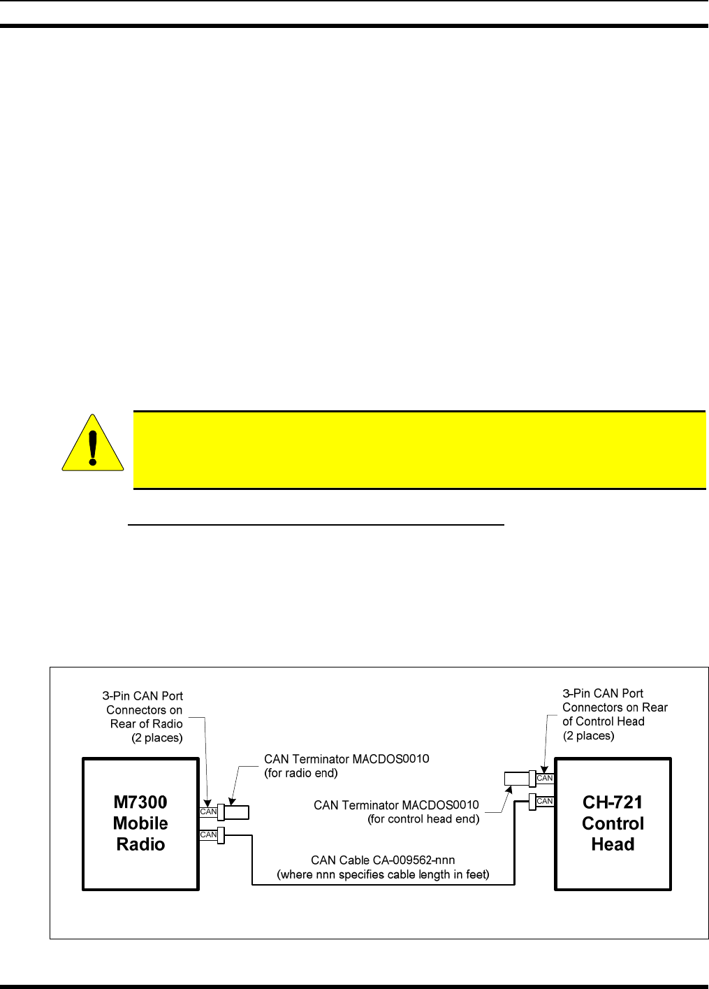
As illustrated in Figure 10-1 below, the motorcycle radio installation requires a CAN cable between the
radio and the control head, a CAN terminator at the radio, and a CAN terminator at the control head.
Figure 5-4 on page 27 shows the radio’s two CAN port connectors, which are located near the center of
the radio’s rear panel. Figure 8-3 on page 37 shows the two CAN port connectors on the control head’s
rear panel.
For Available CAN Cable Lengths and Respective Part Numbers, see Table 4-3 on page 23.
Figure 10-1: CAN Link Connections for a Single Control Head Installation
MM-015371-001
10.1.4.2 Make CAN Link Terminations and Cable Connection
Follow this procedure to make the CAN line interconnections:
1. Mate a CAN terminator (item 14 in Table 4-1) onto either one of the two smaller 3-pin CAN port
connectors on the rear panel of the CH-721. This action makes the CAN termination at the control
head end of the CAN link.
When mating any CAN connection (terminators and cables) to a rear panel connector,
visually align the ¾-moon-shaped keys of the connectors, and then gently push and
turn the outer locking ring of the plug (male) connector clockwise until it stops. A mild
click will be sensed to confirm proper mating. Without visual alignment as a guide, it
is possible with excessive force to mate the CAN connectors improperly. Damage to
the connector(s) may result. Therefore, visual alignment is recommended when mating
CAN connectors.
2. Obtain a CAN cable and mate it to the other CAN port connector on the rear panel of the CH-721.
Typically, item 13 in Table 4-1 is utilized.
3. Make a service loop in the cable near the back of the control head.
4. Route the cable from the rear of the control head to the weather-resistant motorcycle radio case. If the
control head is mounted on the motorcycle’s handlebars, leave sufficient slack in the cable to allow
for full handlebar steering/travel without any stretching of the cable. Protect the cable from chafing.
5. Route the CAN cable it into the case by passing it through the square hole in the bottom floor case
6. Mate this end of the cable to one of the two CAN port connectors on the rear panel of the radio.
7. Mate another CAN terminator to the other CAN port connector on the rear panel of the radio. This
action makes the CAN termination at the radio-end of the CAN link.
8. Loop, tie and stow the excess cable as necessary, leaving a service loop at the back of the radio and at
the back of the control head.
10.1.5 Control Head Power Cable Installation
Plan the route of the control head’s DC Power Cable carefully. Do not route the cable where it will be
damaged by heat sources or by casual contact, and protect it from wire chafe per standard installation
methods. The following procedures are recommended:
10.1.5.1 Install DC Power Cable and Make Power and Ground Connections
1. Connect the control head’s DC Power Cable (item 10 in Table 4-1) to the large 3-pin connector at the
rear of the head. Visually align the key and gently push and turn the outer locking ring clockwise until
it stops. A click will be sensed to confirm proper mating.
2. Protect the wires of this cable by inserting them into an appropriate-length high-temperature tubing,
loom or wrap (not supplied). Typically, a 4 to 5-foot length of tubing/loom/wrap is required.
3. Make a service loop in the cable near the back of the control head.
4. Route the cable (within the tubing/loom/wrap) to the frame of the motorcycle. If the control head is
mounted on the motorcycle’s handlebars, leave sufficient slack to allow for full handlebar
steering/travel without any stretching of the cable. This length of the cable must be in
tubing/loom/wrap. Tie and stow as necessary.
46
MM-015371-001
47
5. Route the cable to the radio case at the rear of the motorcycle and then pass it through the square hole
in the bottom floor of the case.
CAUTION
Do not install any wiring or fuse holders over or in the near vicinity of the motorcycle’s
engine, or near other hot items such as exhaust pipes and mufflers. Excessive heat can
cause permanent damage to these components.
6. Cut excess length from the red and black wires of the cable, leaving enough length for a service loop
inside the radio case, near the Alternator Whine Reject Filter. The red and black wires connect to two
(2) studs on the filter. The white wire is connected in the procedure that follows.
7. Strip approximately ¼-inch of insulation from the end of the black wire and crimp a #10-stud ring
terminal to it.
8. Remove the nut from the filter’s ground stud (stud labeled “NEG”) and slip the ring terminal with the
black wire onto this stud. Three (3) black wires should be connected to this stud. Reinstall the nut
and tighten it securely.
9. Strip approximately ¼-inch of insulation from the end of the red wire and crimp a #10-stud ring
terminal to it.
10. Obtain one of the waterproof (HFB-type) fuse holders included with the control head’s DC Power
Cable.
11. Prepare to splice this waterproof fuse holder into the red wire by cutting it again, approximately three
(3) to six (6) inches from the end with the ring terminal.
12. Strip both wire ends back approximately ⅜-inch, place a fuse holder shell on each wire, and securely
crimp a fuse holder terminal to each wire end. Before crimping, verify fuse holder shells are oriented
in the correct directions (i.e., with each large end towards the wire end).
13. Remove the nut from the filter’s DC output stud (stud labeled “RADIO +”) and slip the red wire’s
ring terminal onto the stud. Three (3) red wires should be connected to this stud. Reinstall the nut and
tighten it securely.
14. Obtain the 5-amp AGC-type fuse included with the cable, and install it into the fuse holder.
15. Label this fuse holder and red wire appropriately (e.g., “Control Head Main Power: 5-AMP FUSE”).
CAUTION
The fuse for the control head’s red wire is rated at 5 amperes. The 3-amp fuse included
with the cable must not be used for fusing the control head’s main DC power. It fuses
the head’s white wire.
10.1.5.2 Connect DC Power Cable’s White Wire
A review of the information presented in Section 10.1.1 (page 42) may be beneficial at this time. As
required per the chosen power-up configuration, connect the white wire by following one of the three
procedures presented in the respective sub-section that follows.
10.1.5.2.1 Control Head and Radio Turn on with Vehicle’s Ignition Switch/Key
With this wiring configuration, the control head and radio automatically turn on and off with the vehicle’s
ignition switch/key. The white wire of the control head’s DC Power Cable is sometimes referred to as the
“white ignition switch wire” or the “ignition sense input wire.” In this configuration, the white wire
connects to a switched power source, typically identified as “Accessory” power, that switches on and off

MM-015371-001
with the vehicle’s ignition switch/key. When using this configuration, the CH-721 control head’s
on/off/volume control must be left in the on position for automatic power-up/down to function properly.
The white ignition sense wire must be connected to a fused power source that switches
from approximately zero volts to approximately +13.6 volts when the vehicle’s ignition
switch/key is turned from the OFF position to the ACCESSORY and RUN positions.
Use of a switched power source that is subject to voltage changes as a result of other
actions may result in undesirable radio operation and/or a degradation of radio
performance.
1. Locate the vehicle’s switched ignition or “Accessory” power connection point that will be used for
the switched ignition 12-volt DC power source. This point is typically located at or near the vehicle’s
fuse panel. Consult the motorcycle manufacturer’s wiring diagram as necessary.
2. Route the white wire of the control head’s DC Power Cable to the area near this connection point.
Protect the wire from heat and chafing as necessary.
3. Obtain one of the waterproof (HFB-type) fuse holders included with the control head’s DC Power
Cable.
4. Cut excess length from the white wire and splice the fuse holder into it, near the location of the
connection point.
5. Using an appropriate electrical terminal, connect the white wire to the switched power connection
point. An open-barrel spade terminal is included with the cable for this purpose, but another type of
terminal (not supplied) may be used as required.
6. Obtain the 3-amp AGC-type fuse included with the cable, and install it into the fuse holder.
7. Tie and stow all wiring as necessary so it remains out of the way of casual contact and wire chafe is
avoided.
10.1.5.2.2 Control Head and Radio Turn On with a Manual Switch
With this wiring configuration, the control head and radio are manually turned on and off via an on/off
switch mounted separately from the control head and radio, not through the vehicle’s ignition switch/key.
This configuration is used when, for example, the radio must remain on even when the ignition key must
be removed from the vehicle and a separate on/off switch is acceptable and/or required. In this
configuration, the white wire connects to a fused switched power source such as that provided by a toggle
switch mounted on the vehicle’s instrument panel. When using this configuration, the CH-721 control
head’s on/off/volume control must be left in the on position for automatic power-up/down to function
properly.
1. Route the white wire of the control head’s DC Power Cable to an area near the location of the panel-
mounted on/off switch. Protect the wire from heat and chafing as necessary.
2. Cut a short section (6 to 8 inches) off the end of the white wire and strip the ends.
3. Obtain one of the waterproof (HFB-type) fuse holders included with the control head’s DC Power
Cable, and crimp one half of it to one end of the short section of wire.
4. Using an appropriate electrical terminal, connect this short white wire to unswitched 12-volt DC
power source at or near the vehicle’s fuse box.
5. Cut another section of white wire from the cable. This wire must be long enough to reach from this
fuse holder to the location of the panel-mounted on/off switch.
6. Strip one end of this wire and crimp the other half of the waterproof fuse holder to this wire end.
48

MM-015371-001
7. Strip the other end of this wire and, using an appropriate electrical terminal, connect it to the common
terminal of the switch.
8. Connect the white wire of the power cable to the load (switched) side of the switch.
9. If not already, mount the switch to the motorcycle’s instrument panel, or other customer-selected
location.
10. Obtain the 3-amp AGC-type fuse included with the cable, and install it into the fuse holder.
11. Tie and stow these wires as necessary so they remain out of the way of casual contact and wire chafe
is avoided.
12. Label this power switch accordingly. For example: “RADIO ON/OFF.”
10.1.5.2.3 Control Head and Radio Are “Hot Wired”
In the “hot-wired” configuration, the control head and radio are turned on and off only by the control
head’s on/off/volume control located on the front panel of the control head. In this configuration, the
control head’s white wire must be connected to unswitched and fused 12-volt vehicle power. Follow the
procedure presented in Section 10.1.5.2.1, except connect the white wire to unswitched battery power
instead of switched (“Accessory”) power.
49
MM-015371-001
11 MICROPHONE ATTACHMENT
There are several versions of microphones available for use with the radio. Each has a 17-pin flush-mount
type connector that mates with the mic connector on the front panel of the control head. The mic’s
connector includes a captive thumbscrew that secures it to the mic connector on the front panel of the
control head. A microphone clip is included with each microphone. The radio can be configured to
provide a monitor function when the microphone is cradled in the clip. Connect the mic to the control
head and install the clip as follows:
1. Select a mounting surface location that has clearance for the mic when it is clipped to the clip, and
then attach the microphone clip to the surface. The use of self-locking hardware (i.e., machine screws
with washers and self-locking nuts) is recommended. Tighten securely.
2. Using the microphone clip as a template, drill mounting holes in the surface of the selected location.
3. The microphone clip must be grounded to the vehicle’s chassis. If not mounted to a grounded metal
surface, complete this requirement by adding a jumper wire attached from chassis ground to the clip.
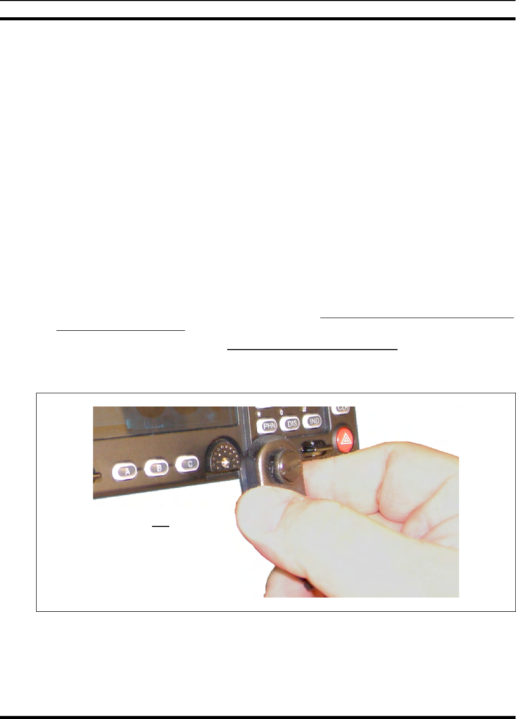
4. As illustrated in Figure 11-1, grasp the mic’s connector with a thumb and index finger on the sides of
the connector just adjacent to the thumbscrew.
5. Position the connector in front of the control head’s mic connector so the mic cable’s stain relief is
hanging down and out at an approximate 45 degree angle.
6. Mate the two connectors by pressing them fully together. Do not apply any force to the thumbscrew
when mating the connectors.
7. Tighten the thumbscrew finger-tight. Do not use a screwdriver to tighten it.
8. Clip the microphone to the clip.
As illustrated, do not apply any
force to the thumbscrew when
mating the mic connectors.
Figure 11-1: Attaching the Microphone to the CH-721Control Head
50
MM-015371-001
51
12 OPTIONAL CABLES
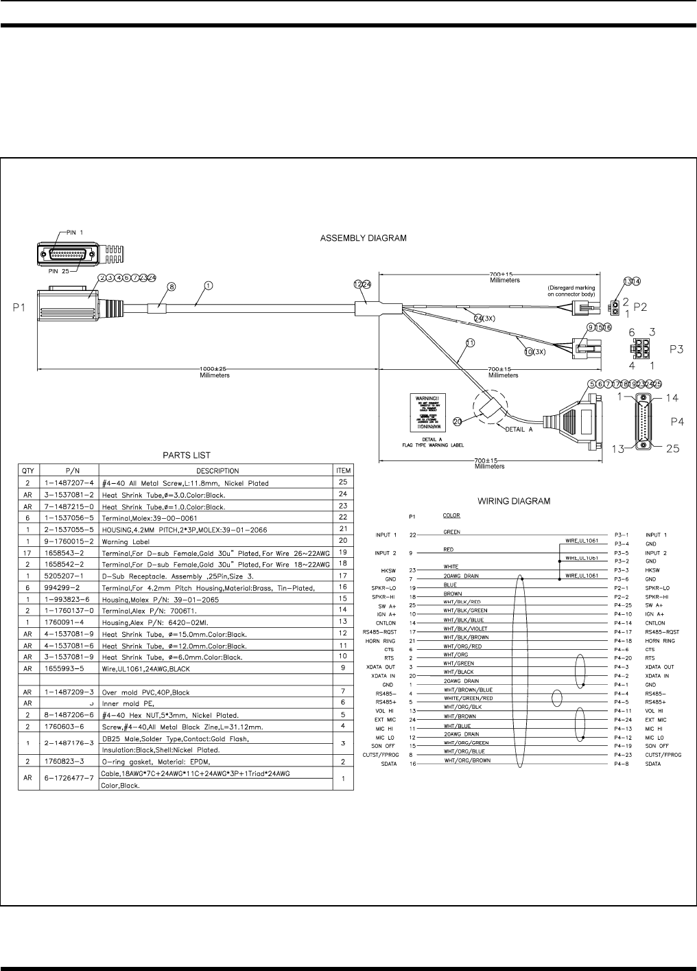
12.1 M5300/M7300 OPTION CABLE CA-012349-001
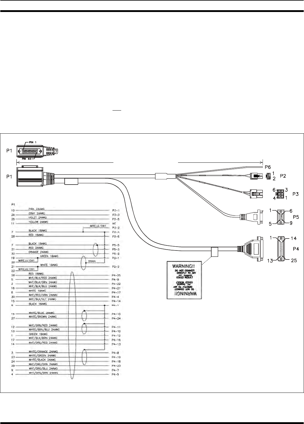
M5300/M7300 Option Cable CA-012349-001 connects to the 44-pin I/O cable connector on the rear of
the radio. It breaks out into several smaller standardized connectors, allowing straightforward access to
external I/O interfaces provided by the radio. The cable also shortens radio removal and re-installation
time when required. The cable is shown in Figure 12-1 below. Its 44-pin D-subminiature connector that
mates with the connector on the rear of the radio is identified P1.
P2, the cable’s 2-pin connector, provides connections for an external speaker in a front-mount M7300
mobile radio installation. P2 is not used in motorcycle installations, which employ a remote-mount
M5300/M7300 mobile radio. In this case, the speaker connection is made at the rear of the CH-721
control head as the audio amplifier in the control head drives the external speaker.
Approximately 66 inches
(170 centimeters)
(Pin-Out
View)
(Side View)
WIRING DIAGRAM
ASSEMBLY DIAGRAM
(Made From PS-CA-012349 Rev. -)
Figure 12-1: M5300/M7300 Option Cable CA-012349-001
MM-015371-001
52
P3, the cable’s 6-pin connector, is a connector for basics accessories (e.g., hookswitch, etc.).
P4, the cable’s 25-pin D-subminiature (DB-25) connector, provides audio and data connections for
connections to optional equipment such as an external siren and light system (e.g., Federal Signal SS2000
SmartSiren®).
P5, the cable’s 9-pin D-subminiature (DB-9) connector, provides NMEA-formatted GPS serial data
connections for the external computer processing the NMEA-formatted GPS data received by the radio’s
internal GPS receiver. See Section 13 on page 57 for additional information.
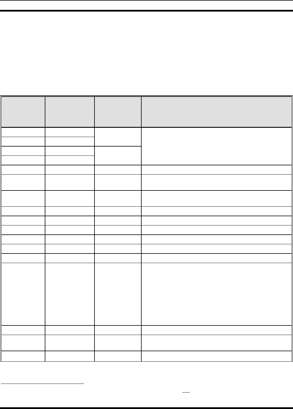
Table 12-1: M5300/M7300 Option Cable CA-012349-001 Interconnections
44-PIN I/O
CABLE
CONNECTOR
P1 PIN
SIGNAL NAME TO/FROM DESCRIPTION
19 SPKR1
20 SPKR1
P2 pin 1
21 SPKR2
22 SPKR2
P2 pin 2
Speaker Audio Outputs 1 and 2
(These outputs are not used in a motorcycle installation,
since the audio amplifier in the CH-721 control head
drives the external speaker.)
10 OUT2 P3 pin 1 Digital Output 2 (open-collector)
7 GND P3 pins 2 & 4 Chassis Ground
(fused on radio’s PK Board at 3.15 amps)
26 HKSW P3 pin 3 Hookswitch Digital Input.
Active = Ground. Inactive = Open
25 INP2 P3 pin 5 Digital Input 2
28 SWA+ P3 pin 6 Switched A+ (DC Power) Output
8 GND P4 pin 1 Chassis ground (fused on PK Board at 3-amps)
30 DGPS_DATA P4 pin 4 GPS Serial Data
4 EXTRX P4 pin 5 External Rx Audio Output (for non-CAN based radio)
9 EXTMOD P4 pin 7 External Tx Audio Input (for non-CAN based radio)
3 SDATA P4 pin 8
For a motorcycle installation which employs a remote-
mount M5300/M7300 radio, see footnote 2. In a front-
mount M5300/M7300 radio installation, this pin for the
siren/PA interface is the siren serial data output (open-
collector/open-drain) from the radio’s mounted (local)
CH-721. It serially transfers siren and light control data
from the head/radio to a connected third-party siren and
light system (e.g., Federal Signal SS2000 SmartSiren®).
Data rate = 1200 bps.
5 FDISC P4 pin 9 Buffered Discriminator Audio
13 ALO P4 pin 10 Audio Ground/Reference
(fused on radio’s PK Board at 3.15 amps)
12 MICHI P4 pin 11 For a motorcycle installation which employs a remote-
2 In a motorcycle installation, this pin on the radio’s DB-44 connector should not be used. It is not functional. Instead, the
respective pin on the CH-721 Option Cable’s female DB-25 pin connector. See Section 12.3 for additional information.

MM-015371-001
53
Table 12-1: M5300/M7300 Option Cable CA-012349-001 Interconnections
44-PIN I/O
CABLE
CONNECTOR
P1 PIN
SIGNAL NAME TO/FROM DESCRIPTION
1 EXTALO P4 pin 12
mount M5300/M7300 radio installation, see footnote 2. In
a front-mount M5300/M7300 radio installation, these two
pins provide the public address (PA) mic audio from the
mounted (local) CH-721 to the siren and light system
(e.g., Federal Signal SS2000 SmartSiren®).
14 VOLHI P4 pin 13 Volume High
15 CTLON P4 pin 14 Control On Digital Output (for non-CAN based radio)
16 XTONEENC P4 pin 15 External Tone Encode Audio (for non-CAN based radio)
17 XTONEDEC P4 pin 16 External Tone Decode Audio (for non-CAN based radio)
6 EXTALO P4 pin 17 External Audio Output (Balanced, Low; for non-CAN
based radio)
24 HORNRING P4 pin 18
For a motorcycle installation which employs a remote-
mount M5300/M7300 radio, see footnote 2. In a front-
mount M5300/M7300 radio installation, this pin for the
siren/PA interface is the horn/ring logic input to the
radio’s mounted (local) CH-721. When a connected third-
party siren and light system (e.g., Federal Signal
SmartSiren® SS2000) has its horn/ring function active,
this input is used to signal the head/radio as such.
23 SONOFF P4 pin 19
For a motorcycle installation which employs a remote-
mount M5300/M7300 radio, see footnote 2. In a front-
mount M5300/M7300 radio installation, this pin for the
siren/PA interface is the siren on/off logic output (open-
collector) from the radio’s mounted (local) CH-721. It is
the signal that powers the connected third-party siren and
light system (e.g., Federal Signal SmartSiren®SS2000)
on and off.
18 INP1 P4 pin 21 Digital Input 1 (for non-CAN based radio)
2 OUT1 P4 pin 22 Digital Output 1 (open-collector; for non-CAN based
radio)
29 TXENB+ P4 pin 23 Transmit Enable B+ (for non-CAN based radio)
27 EXTMIC P4 pin 24 External Mic Audio Input
28 SWA+ P4 pin 25 Switched A+ DC Power Output
(for non-CAN based radio)
32 GPS_NMEA_RX P5 pin 2 Serial Rx Input for GPS NMEA-Formatted Serial Data
31 GPS_NMEA_TX P5 pin 3 Serial Tx Output for GPS NMEA-Formatted Serial Data
7 GND P5 pin 5 Ground for GPS Serial Data Signals
(fused on radio’s PK Board at 3.15 amps)
11 IGNITION (no connection) Unused/Spare ignition sense input.
33
through
44 — (no connections) These pins of P1 are not used/not connected.
MM-015371-001
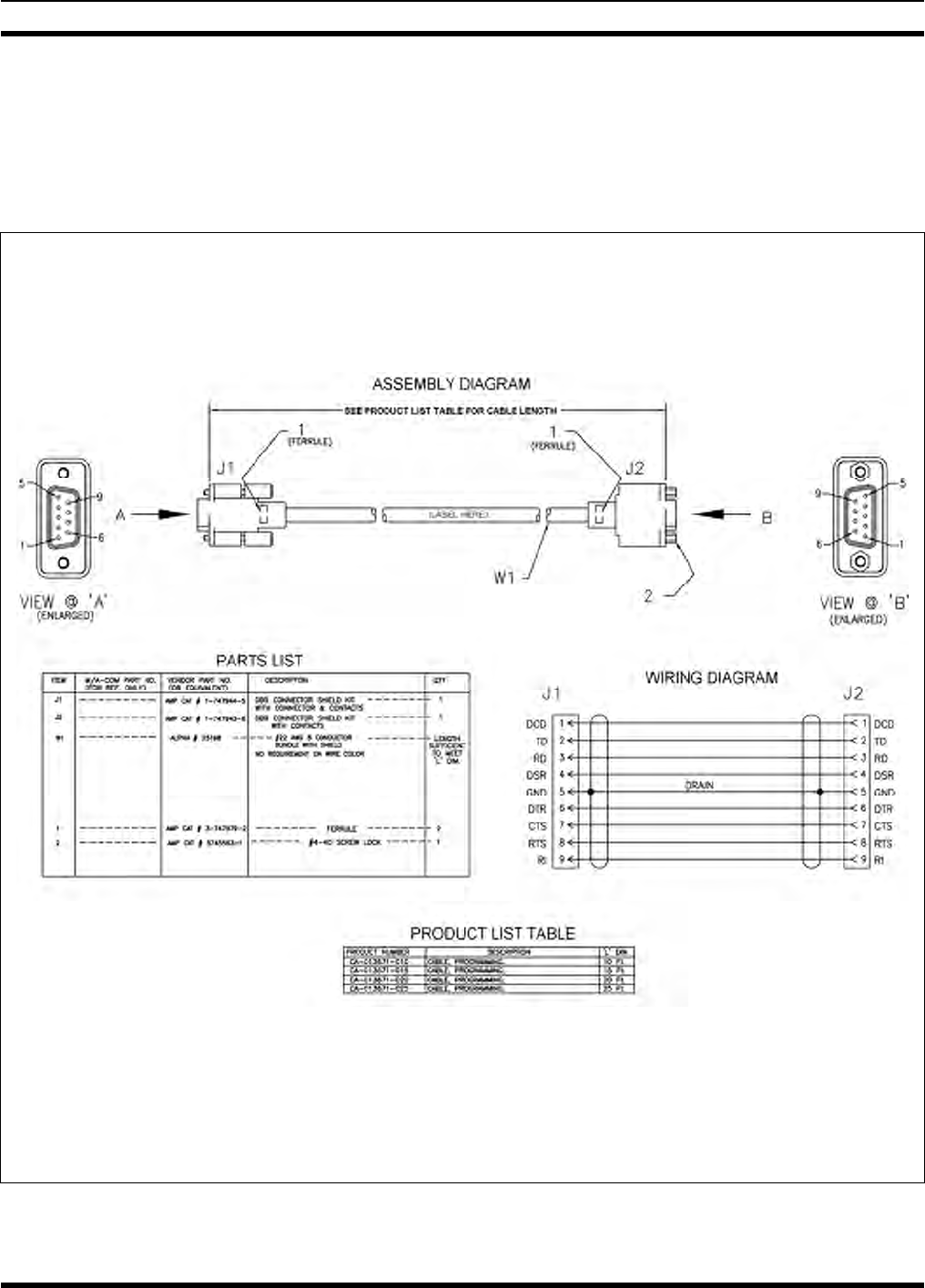
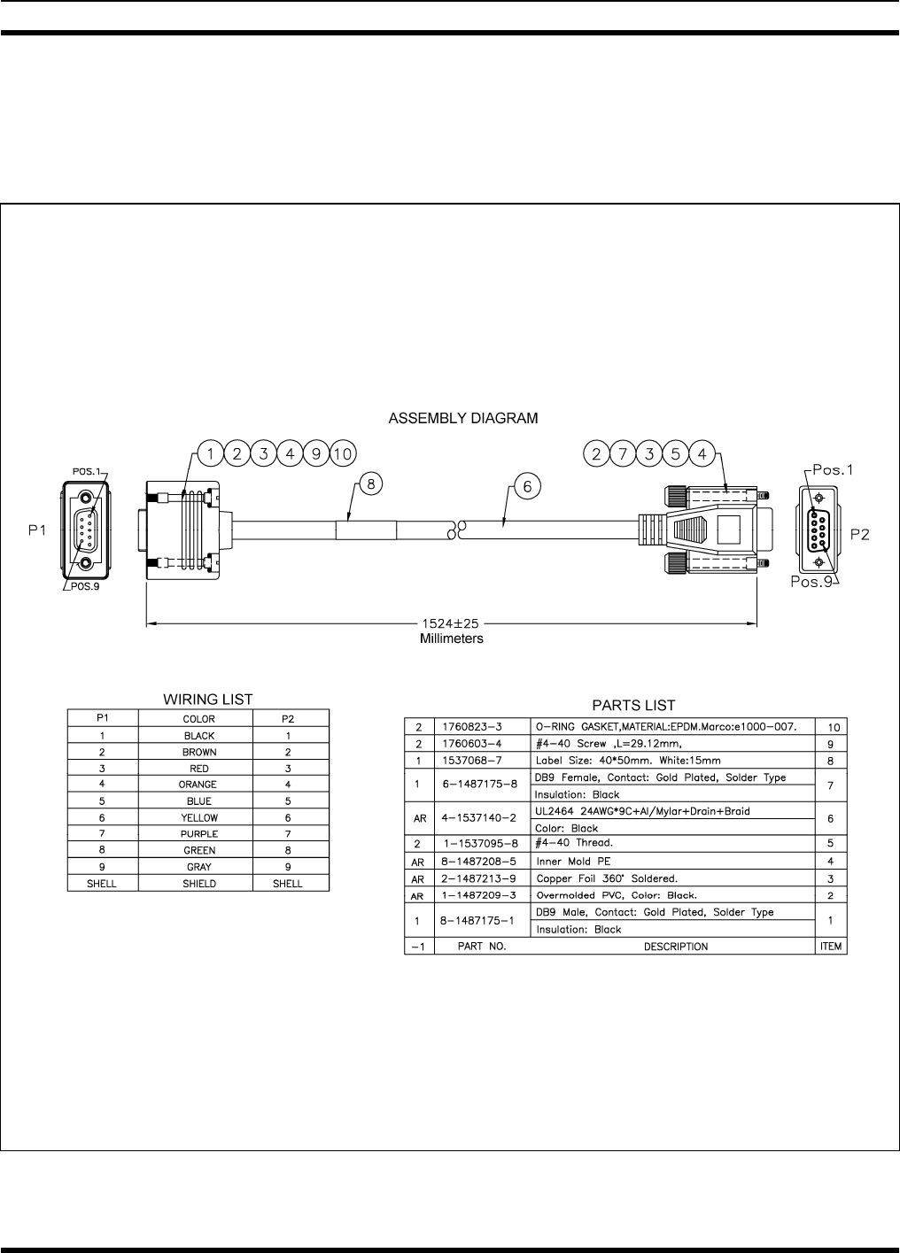
12.2 SERIAL PROGRAMMING CABLE CA-013671
Serial Programming Cable CA-013671-010 (10 feet long) and CA-013671-020 (20 feet long) can be used
to program and configure the M7300 mobile radio via a Personal Computer. This cable has a female
DB-9 connector on one end for connection to the PC’s serial port and a male DB-9 connector on the other
end for connection to the serial port on the rear of the radio. The cable’s assembly and wiring diagrams
are shown in Figure 12-2 below.
(Made From PS-CA-013671 Rev. -)
Figure 12-2: Programming Cables CA-013671-010 and -020
54
MM-015371-001
12.3 CH-721 OPTION CABLE CA-011854-001
CH-721 Option Cable CA-011854-001 can be used to connect optional equipment to the 25-pin
D-subminiature (DB-25) connector on the rear of the CH721. This cable expands the connections
available at the 25-pin connector to three (3) separate connectors. The cable’s assembly and wiring
diagrams are shown in Figure 12-3 below.
(Made From PS-CA-011854 Rev. D)
Figure 12-3: CH-721 Option Cable CA-011854-001
55
MM-015371-001
12.4 CH-721 SERIAL PROGRAMMING CABLE CA-104861
Serial Programming Cable CA-104861 (5 feet) can be used to program and configure the CH-721 control
head via a Personal Computer. This cable has a female DB-9 connector on one end for connection to the
PC’s serial port and a male DB-9 connector on the other end for connection to the serial port on the rear
of the head. The cable’s assembly and wiring diagrams are shown in Figure 12-4 below.
(Made From PS-CA-104861 Rev. A)
Figure 12-4: Programming Cable CA-104861
56
MM-015371-001
13 GPS NMEA-FORMATTED SERIAL DATA
CONNECTION
To obtain GPS NMEA-formatted serial data from the radio, use of the M5300/M7300 Option Cable
CA-012349-001 is required. Follow this procedure to complete the GPS NMEA-formatted serial data
connections:
1. Obtain M5300/M7300 Option Cable CA-012349-001. Each “leg” of this cable is approximately
65 inches long (166 centimeters).
2. Connect the cable’s 44-pin D-subminiature (DB-44) male connector to the DB-44 female connector
on the rear panel of the radio. Tighten the two jackscrews with a small flathead screwdriver. Do not
over-tighten.
3. Connect the cable’s DB-9 female connector to the computer’s serial port DB-9 male connector —
either directly or with an optional MAMROS0055 serial cable — and tighten the screws until firm.
Route the cabling as required.
4. Follow the manufacturer’s instructions on processing the NMEA-formatted GPS data from the radio.
If the M5300/M7300 Option Cable is not available, a 3-wire serial cable can be field-
fabricated. On the radio end, this cable must interface to the three GPS-related signals of
the radio’s 44-pin I/O Cable connector (pins 7, 31 and 32). See Table 12-1 for additional
information.
Industry software to process GPS information through this interface is not supported by
M/A-COM.
57
MM-015371-001
14 INITIAL POWER-UP TEST
1. At the radio’s main waterproof (HFB-type) fuse holder installed near the vehicle battery, insert the
15-amp AGC-type fuse that was included with the radio’s DC Power Cable.
2. Tie and stow all fuse holders at this location to prevent excess vibration/movement.
3. Carefully reconnect the vehicle’s battery ground cable.
4. If not already, temporarily connect the mobile antenna cable from the vehicle-mounted mobile
antenna to the female TNC RF connector on the rear panel of the radio. This is a temporary
connection until test procedures in Section 15 are complete.
5. If the installation is wired so the vehicle’s ignition key/switch turns the radio on and off, turn the
switch to the Accessory or Run position.
6. If the control head is not already powered up, do so by rotating its on/off/volume control clockwise
out of the detent position.
7. Verify the control head has powered-up by observing its display. If the display is not lit, refer to
Section 10.1.1 as necessary.
Unlike many mobile radio products, the radio powers-up to the state of last control.
As long as the software configuration parameters have been loaded, successful installation is almost
immediately realized:
• After a short boot-up sequence, the control head displays login information and/or a talk group.
• If no errors are displayed, the installation is most-likely properly wired.
• If an error is displayed, recheck all cable connections, verify all fuses are properly installed, and
verify battery power on the load side of the fuses, etc. If problems persist, contact M/A-COM’s
Technical Assistance Center (see page 17).
• Consult the Operator’s Manual for operational information.
Refer to the following section for performance test information.
58
MM-015371-001
15 PERFORMANCE TESTS
This section includes procedures to verify the performance of the installation’s mobile antenna system.
There are three (3) procedures in this section:
• Changing Operating Mode for Tests
• Testing by Transmitting into a Dummy Load (a 50-Ohm RF Terminator)
• Testing by Transmitting into the Mobile Antenna
The accuracy of test results depends upon a DC power source in the range of 13.8 to
16 volts DC, with a current capacity of greater than 8 amps. Make sure the vehicle’s
battery is fully charged by running the engine for a few minutes before the test, and
keep the engine running during the test procedures. Abide by the following
WARNING!
CAUTION
If the vehicle’s engine must remain running, the vehicle location should be well
ventilated so exhaust fumes from the engine do not cause harm!
If a vehicle equipped with this radio requires jump-starting, the radio installation’s
main AGC fuse (15-amp) should be removed from the holder prior to jump-starting.
Doing so will prevent damage to the radio system.
CAUTION
Prior to installation, the radio’s power level should be configured appropriately. The
wide range of power levels indicated in the following procedures takes into account
such things as: customer’s requirements; measurement errors, especially to include
uncalibrated equipment; cabling losses; and voltage and temperature variations. By no
means should the result from Performance Testing in this section be construed as the
exact value of power level output from the radio, as the value is set and more
accurately measured in the factory. The values obtained in these test procedures
determine a successful installation only.
15.1 CHANGING OPERATING MODE FOR TESTS
To complete tests in this section, placing the radio in a conventional mode and using an average-
responding wattmeter to measure RF transmit power is recommended. However, if the radio is not
programmed for conventional mode operations (i.e., OTP mode is available but ECP mode is not), tests
will require a peak-reading RF wattmeter to measure RF transmit power. To select either conventional or
OpenSky mode, use one of the following procedures:
15.1.1 Changing from OpenSky to Conventional
1. If necessary, apply power to the radio and turn it on.
2. Use the control head’s •/•• Ramp Control to scroll through the menu until Mode Menu appears in
the middle line of the display. This control is shown in Figure 8-1 and in Figure 8-2 on page 36.
3. Use the +/- Ramp Control to select an available conventional channel/system.
59
MM-015371-001
4. Confirm the selection by pressing the MENU button, then toggling the Ramp Control once (to
select Y for Yes), followed by pressing the MENU button again. The radio will enter the selected
mode as indicated by the display.
5. Select a conventional channel for test transmissions using either the •/•• Ramp Control or the
System/Group/Channel Selection Control (required control per programming).
15.1.2 Changing from Conventional to OpenSky
1. If necessary, apply power to the radio and turn it on.
2. Use the control head’s •/•• Ramp Control to scroll through the menu until an OpenSky system’s
name is displayed.
3. After a few seconds, the radio will automatically transition to OTP mode for operations on the
selected OpenSky system.
4. If the radio is not programmed for auto-login, login to the OpenSky system. For login instructions,
refer to the Operator’s Manual (publication MM-014716-001) or the respective Quick-Guide
(publication MM-014368-001) as necessary. The Quick-Guide is included with the radio when it
shipped from the factory.
5. Select a talk group for test transmissions using either the •/•• Ramp Control or the System/-
Group/Channel Selection Control (required control per programming).
15.2 REQUIRED TEST EQUIPMENT
Table 15-1: Required Test Equipment
TEST EQUIPMENT MODEL / PART NUMBER & DESCRIPTION
Average-Responding
Wattmeter
(for conv. measurements)
Bird Electronic Corp. Model 43 (or equivalent) with Type N female
connectors at input and output ports, and with wattmeter slugs appropriate
for the radio’s transmit RF output power capability.
Peak-Reading
Wattmeter
(for OpenSky measurements)
Bird Electronic Corp. Model 4314B (or equivalent) with Type N female
connectors at input and output ports.
RF Coaxial
Jumper Cable
Pasternack Enterprises PE3661-36 (or equivalent) 50-Ohm Coaxial Cable
with TNC male connector and Type N male connector, approximately three
(3) feet in length. The utilized cable must have VSWR below 1.5:1 within
the RF passband.
N-to-TNC
RF Adapter
Pasternack Enterprises PE9090 (or equivalent) Type N male to TNC female
adapter. Required to connect the cable of the vehicle-mounted 800 MHz
antenna to the wattmeter.
50-Ohm RF Terminator
(“Dummy Load”) Pasternack Enterprises PE6106 (or equivalent) 50-ohm RF terminator rated
at greater than 50 watts power, with Type N male connector.
Vehicle-Mounted
Antenna Tests are performed with the vehicle-mounted 800 MHz antenna per the
installation described in Section 7 of this manual.
or
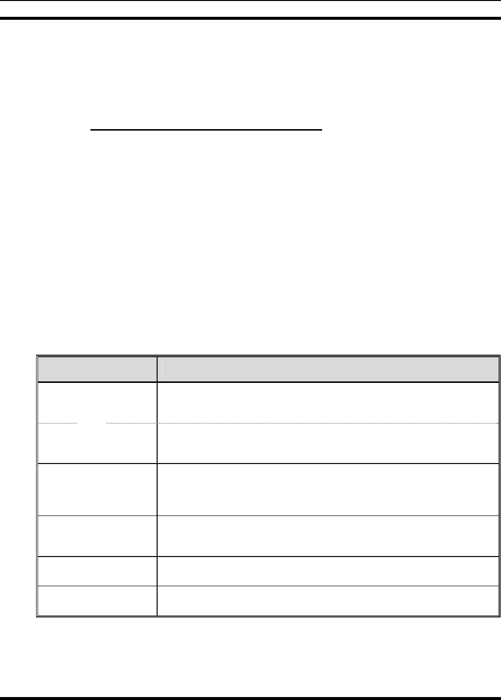
15.3 TRANSMITTING INTO A DUMMY LOAD
1. Using the Type N male to TNC male RF coaxial jumper cable, connect the radio’s antenna connector
to the wattmeter’s input connector. Refer to Figure 15-1 as necessary.
60
MM-015371-001
61
2. Connect the 50-ohm dummy load to the wattmeter’s output connector, in place of the antenna cable
from the mounted mobile antenna.
As previously stated, if conventional mode is not available per radio programming
(i.e., OTP mode is available but ECP mode is not), a peak-reading RF wattmeter is
required to measure RF transmit power. Otherwise, the use of an average-responding
wattmeter is recommended. Recommended wattmeter types are listed in Table 15-1.
3. If not already, turn the radio on and set it to the required operating mode (based upon available radio
programming and test equipment). Refer to Section 15.1 as necessary.
4. Set the radio to a test talk group or conventional channel, if available.
It is recommended that a test talk group/channel be allocated for this testing. This
same group should be used during the antenna test procedure which is presented in the
subsequent section.
Wattmeter
Type N-to-TNC
RF Ada ptor
TNC Male-to-Type N Female
Coaxial Jumper Cable
Slug
(25 W, 400–
1000 MHz) Dummy
Load
V
ehicle-Mounted
700/800 MHz
Antenna
IN
OUT
M7300
Mobile Radio
(Rear View)
Radio’s DC
Power Cable
Installation’s DC
Power Cable
From 13.8-Volt
Fused Power Source
3
-Pin
Connectors
NOTE: CAN cable
connections not indicated.
Figure 15-1: Wattmeter Connections for Antenna System Tests
5. Position the wattmeter’s slug to measure forward RF output power. Rotate it if necessary. The arrow
on the face of the slug must point away from the radio and towards the dummy load for forward
power measurements.
6. For conventional mode transmissions, set the wattmeter to measure average RF power.
For OpenSky mode transmissions, set the wattmeter to measure peak RF power.
7. Key the radio’s transmitter via the microphone’s PTT button.
MM-015371-001
8. For an OpenSky mode transmission, compare the wattmeter’s reading with the target RF output
power range of between 11.8 and 18.9 watts (15 watts ±1 dB). This transmit output power range
assumes the radio is currently configured for high-power transmit.
For a conventional mode transmission, compare the wattmeter’s read with the target RF output power
range of between 27.7 and 44.2 watts (35 watts ±1 dB). This transmit output power range assumes
the radio is currently configured for the high-power transmit.
Transmit only for as long as needed to take the measurement, then immediately
disable the transmission.
9. If the wattmeter reading is within the range, record the measured value in the appropriate space on
the data collection form near the end of this manual.
If the wattmeter reading is outside the range, verify the radio’s power supply voltage (i.e., battery
voltage) is within the specified range, recheck all connections and measure the RF output power
again. If this fails to produce a reading within the range, replace it and repeat this procedure. If
problems persist, contact M/A-COM’s Technical Assistance Center (see page 17).
15.4 TRANSMITTING INTO THE MOBILE ANTENNA
1. Connect the antenna cable from the vehicle-mounted 800 MHz antenna to the wattmeter as shown in
Figure 15-1.
2. If not already, turn the radio on and set it to the required operating mode (based upon available radio
programming and test equipment). Refer to Section 15.1 as necessary.
3. Set the radio to a test talk group or conventional channel, if available.
It is recommended that a test talk group/channel be allocated for this testing.
Otherwise, interference with other radio users in the system may occur. Also, during
transmissions, always observe the RF exposure-related safety information
presented in Section 1.2 (begins on page 6).
4. Position the wattmeter’s slug to measure forward RF output power. Rotate it if necessary. The arrow
on the face of the slug must point away from the radio and towards the antenna for forward power
measurements.
5. For conventional mode transmissions, set the wattmeter to measure average RF power.
For OpenSky mode transmissions, set the wattmeter to measure peak RF power.
6. Key the radio’s transmitter via the microphone’s PTT button.
7. For an OpenSky mode transmission, compare the wattmeter’s reading with the target RF output
power range of between 11.8 and 18.9 watts (15 watts ±1 dB). This transmit output power range
assumes the radio is currently configured for high-power transmit.
For a conventional mode transmission, compare the wattmeter’s read with the target RF output power
range of between 27.7 and 44.2 watts (35 watts ±1 dB). This transmit output power range assumes
the radio is currently configured for the high-power transmit.
Transmit only for as long as needed to take the measurement, then immediately
disable the transmission.
62
MM-015371-001
8. If the wattmeter reading is within the range, record the value in the appropriate space on the data
collection form near the end of this manual.
If the wattmeter reading is outside the range, verify the radio’s power supply voltage (i.e., battery
voltage) is within the specified range, recheck all connections, and measure the forward power again.
If these checks/corrections fail to produce a reading within the range, check all cabling and
connections and repeat the testing procedure to this point. In the event the wattmeter reading still falls
outside the range, replace the antenna, make sure all connections are seated firmly, and repeat the
testing procedure. If problems persist, contact M/A-COM’s Technical Assistance Center (see page
17).
9. Position the wattmeter’s slug to measure reverse (reflected) RF power from the antenna. The arrow
on the face of the slug must point away from the antenna and to the radio to measure reverse power.
10. Key the radio’s transmitter via the microphone’s PTT button.
11. Compare the wattmeter reading with the RF power output range of 2 watts or less.
Transmit only for as long as needed to take the measurement, then immediately disable
the transmission.
12. If the wattmeter reading is within the range, record the value in the appropriate space on the data
collection form near the end of this manual.
If the wattmeter reading is outside the range, make sure the antenna is consistent with the specified
frequency range of the radio. Recheck all antenna connections, and measure the reverse power again.
If the installation employs a ¼-wave unity-gain antenna, observe the NOTE that follows step 8. If
these checks/corrections fail to produce a reading within the range, replace the antenna and repeat the
entire antenna test procedure. Any value exceeding the maximum allowable reflected power value
will result in a diminished RF output signal. If problems persist, contact M/A-COM’s Technical
Assistance Center (see page 17).
13. Disconnect the coaxial cable jumper and wattmeter.
14. Permanently connect the cable from the vehicle-mounted 800 MHz antenna to the radio’s antenna
cable by mating the two TNC connectors together. Use two pairs of soft-jaw pliers to gently tighten
this connection. Do not over tighten and do not twist either cable.
15. Make several test calls on the radio system to verify operation of the mobile radio. Before making the
calls, select other talk groups or conventional channels, as required to verify operation.
To prevent RF leakage and ensure peak performance, make sure the RF connectors are
tight, but do not over-tighten so connector damage will not occur.
Improper installation of the RF cables may lead not only to poor radio
performance but also to harmful exposure to RF electromagnetic energy.
Testing is complete. The radio is now ready for normal communications.
63
MM-015371-001
64
15.5 TEST PERFORMANCE DATA FORM
Enter the information requested on this data collection form. Clip this form and file it as a permanent record of
the tested performance of the M7300 mobile radio installation.
Clip
Here
Company Performing Installation Technician Performing Test
Date of Test
(mm/dd/yyyy)
Mobile Radio Serial Number Antenna Make and Model Numbers
Power into a Dummy
Load
Watts
Forward Power with
Antenna Reflected Power
with Antenna
Watts
Watts

MM-015371-001
16 COMPLETE THE INSTALLATION
Double-check the following items before considering the installation completed:
• Verify all newly installed mechanical hardware is mounted securely and all respective mounting
hardware is tight.
• Verify all electrical interconnections are connected properly and the associated connector attachment
hardware is tight. Pay special attention to all RF antenna cables!
• Verify all related fuses are correctly installed and properly rated.
• Verify all electrical cables and wiring are tied, stowed, and protected so they are out of the way of
casual contact, away from sources of extreme heat, and wire chafing cannot occur. Pay special
attention to all RF antenna cables!
• To prevent fumes from entering the vehicle’s passenger compartment, seal the hole/grommet/wire
combination at the firewall with a silicon-based sealer.
• Verify all vehicle components are properly reinstalled such as kick panels, headliners, and seats.
• If the installation includes a separately-mounted on/off power switch for manually turning the radio
(and possibly others systems) on and off, verify it is labelled accordingly. For example: “Radio
ON/OFF.”
• Remove all tools and unused hardware from the vehicle.
• Verify the test performance data has been recorded on the data collection form shown in this manual.
65

MM-015371-001
66
17 WARRANTY
A. M/A-COM, Inc. (hereinafter "Seller") warrants to the original purchaser for use (hereinafter "Buyer")
that Equipment manufactured by or for the Seller shall be free from defects in material and
workmanship, and shall conform to its published specifications. With respect to all non-M/A-COM
Equipment, Seller gives no warranty, and only the warranty, if any, given by the manufacturer shall
apply. Rechargeable batteries are excluded from this warranty but are warranted under a separate
Rechargeable Battery Warranty (ECR-7048).
B. Seller’s obligations set forth in Paragraph C below shall apply only to failures to meet the above
warranties occurring within the following periods of time from date of sale to the Buyer and are
conditioned on Buyer’s giving written notice to Seller within thirty (30) days of such occurrence:
1. for fuses and non-rechargeable batteries, operable on arrival only.
2. for parts and accessories (except as noted in B.1) sold by Seller’s Service Parts Operation, ninety
(90) days.
3. for P7200, P7100IP, P5400, P5300, P5200, P5100, P3300, PANTHER™ 405P and 605P, M7300,
M7200 (including V-TAC), M7100IP, M7300 and M3300 radios, two (2) years, effective
10/01/2007.
4. for all other equipment of Seller’s manufacture, one (1) year.
C. If any Equipment fails to meet the foregoing warranties, Seller shall correct the failure at its option (i)
by repairing any defective or damaged part or parts thereof, (ii) by making available at Seller’s factory
any necessary repaired or replacement parts, or (iii) by replacing the failed Equipment with equivalent
new or refurbished Equipment. Any repaired or replacement part furnished hereunder shall be
warranted for the remainder of the warranty period of the Equipment in which it is installed. Where
such failure cannot be corrected by Seller’s reasonable efforts, the parties will negotiate an equitable
adjustment in price. Labor to perform warranty service will be provided at no charge during the
warranty period only for the Equipment covered under Paragraph B.3 and B.4. To be eligible for no-
charge labor, service must be performed at a M/A-COM factory, by an Authorized Service Center
(ASC) or other Servicer approved for these purposes either at its place of business during normal
business hours, for mobile or personal equipment, or at the Buyer’s location, for fixed location
equipment. Service on fixed location equipment more than thirty (30) miles from the Service Center or
other approved Servicer’s place of business will include a charge for transportation.
D. Seller’s obligations under Paragraph C shall not apply to any Equipment, or part thereof, which (i) has
been modified or otherwise altered other than pursuant to Seller’s written instructions or written
approval or, (ii) is normally consumed in operation or, (iii) has a normal life inherently shorter than the
warranty periods specified in Paragraph B, or (iv) is not properly stored, installed, used, maintained or
repaired, or, (v) has been subjected to any other kind of misuse or detrimental exposure, or has been
involved in an accident.
E. The preceding paragraphs set forth the exclusive remedies for claims based upon defects in or
nonconformity of the Equipment, whether the claim is in contract, warranty, tort (including
negligence), strict liability or otherwise, and however instituted. Upon the expiration of the warranty
period, all such liability shall terminate. The foregoing warranties are exclusive and in lieu of all other
warranties, whether oral, written, expressed, implied or statutory. NO IMPLIED OR STATUTORY
WARRANTIES OF MERCHANTABILITY OR FITNESS FOR PARTICULAR PURPOSE SHALL
APPLY. IN NO EVENT SHALL THE SELLER BE LIABLE FOR ANY INCIDENTAL,
CONSEQUENTIAL, SPECIAL, INDIRECT OR EXEMPLARY DAMAGES.
This warranty applies only within the United States.
M/A-COM, Inc. M/A-COM, Inc.
1011 Pawtucket Blvd. 221 Jefferson Ridge Parkway
Lowell, MA 01853 Lynchburg, VA 24501
1-877-OPENSKY 1-800-528-7711 ECR-7047F

Tyco Electronics Wireless Systems Segment
221 Jefferson Ridge Parkway
Lynchburg, Virginia 24501
(Outside USA, 1-434-385-2400) Toll Free 1-800-528-7711
www.macom-wireless.com Printed in U.S.A.