HARRIS TR-0055-E M7300 VHF 50W Mobile Radio User Manual Manual 1
HARRIS CORPORATION M7300 VHF 50W Mobile Radio Manual 1
UserManual.wiki
>
HARRIS
>
TR-0055-E User Manual
>
Manual 1
Contents
1.
Manual 1
2.
Manual 2
3.
Manual 3
4.
manual 2
Manual 1
Navigation menu
Upload a User Manual
Namespaces
Wiki Guide
HTML
PDF
Info
Views
User Manual
Discussion / Help
Navigation

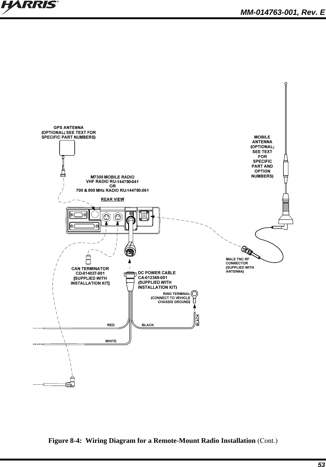
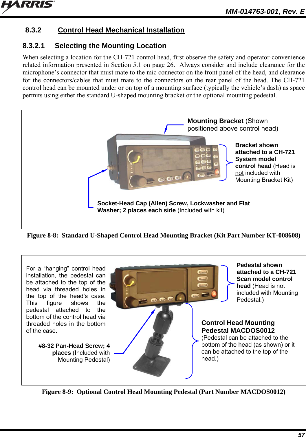
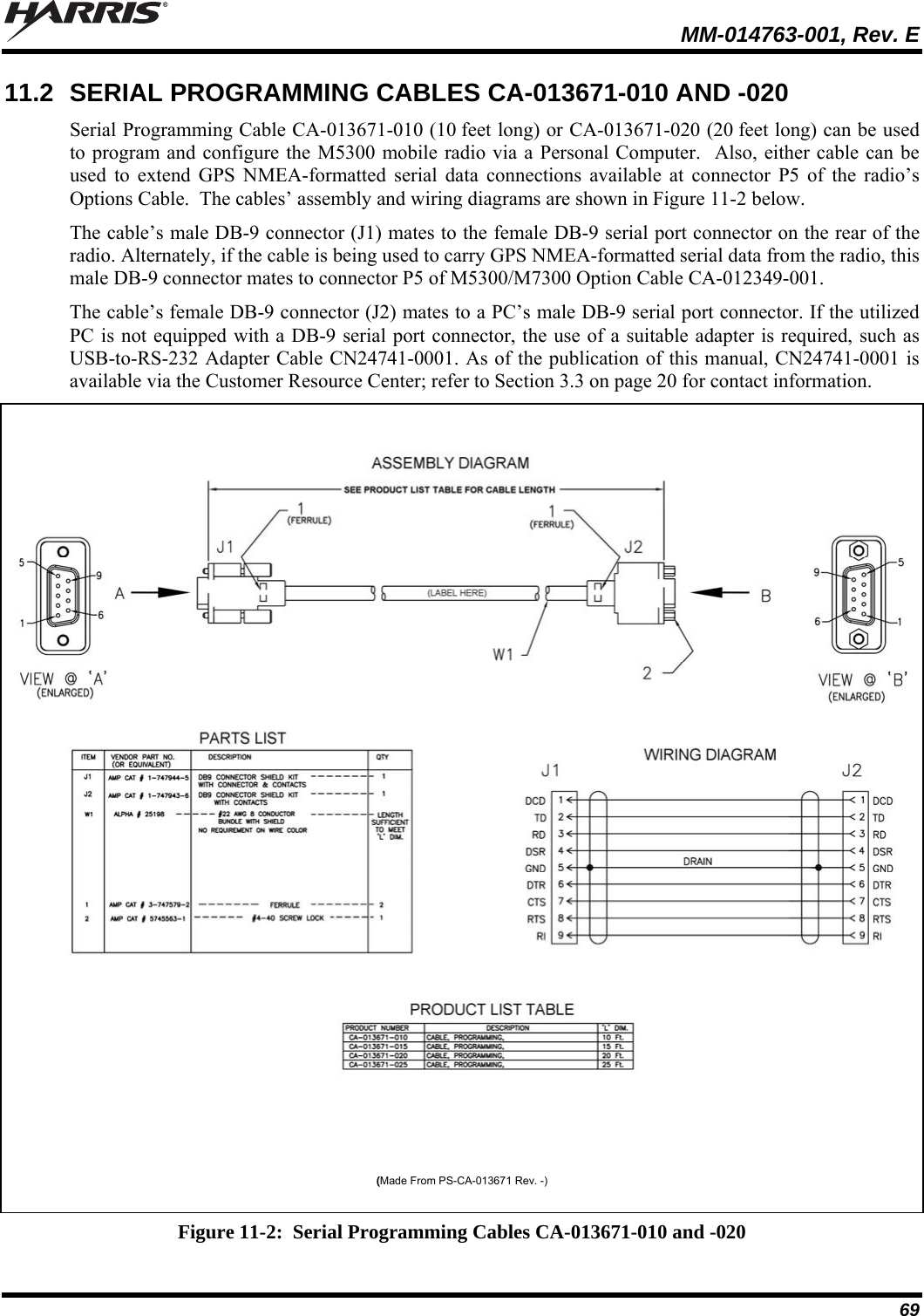
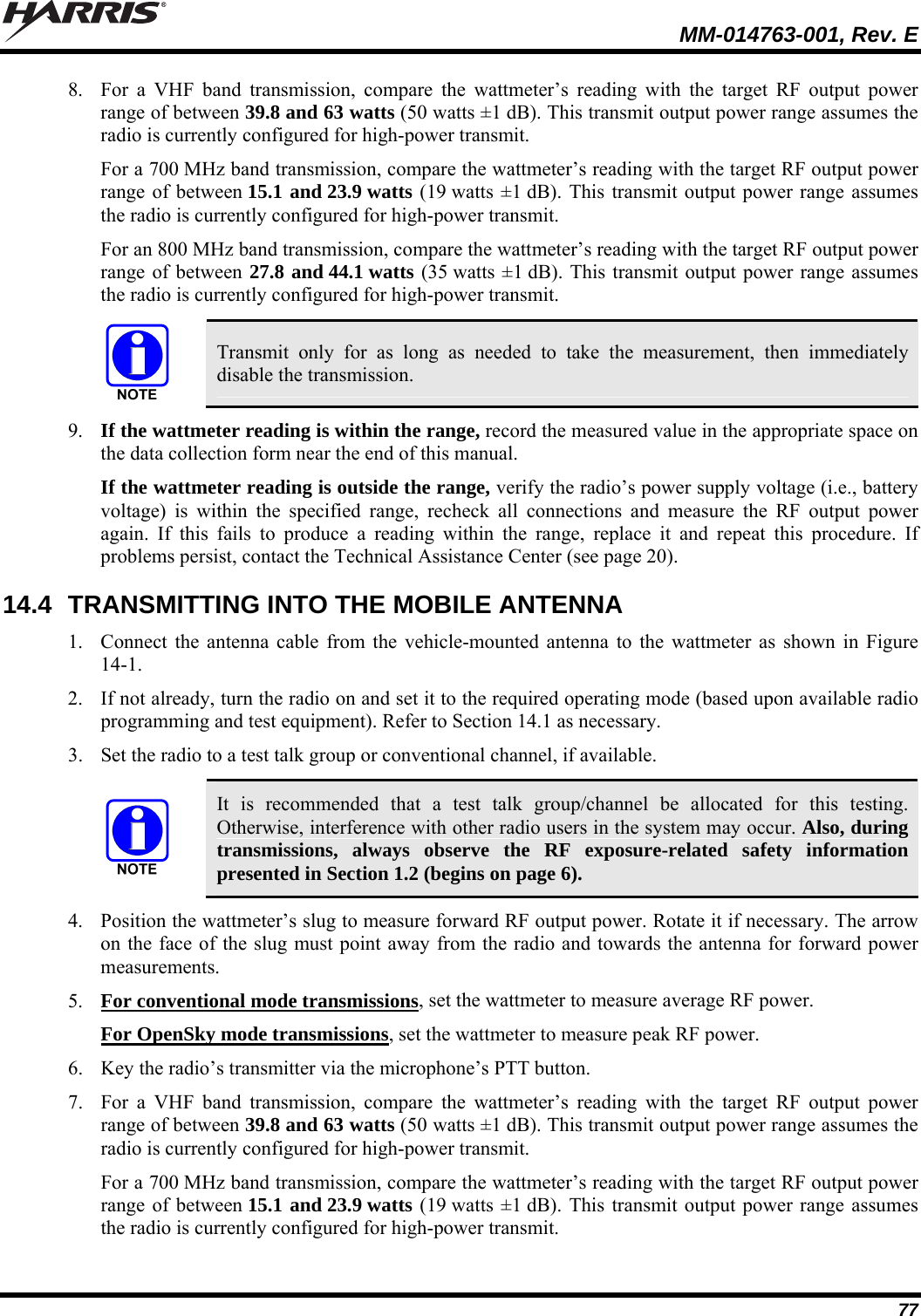
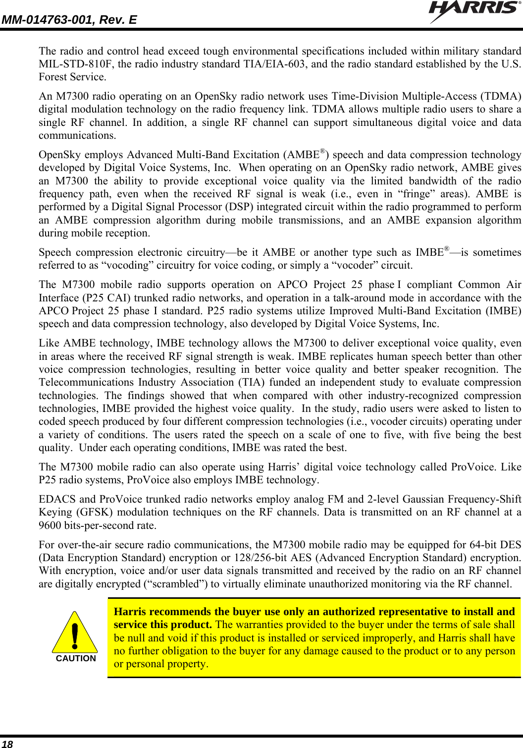
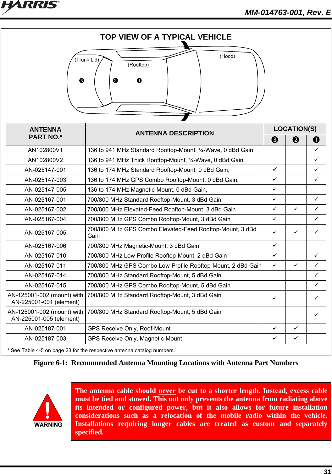
![MM-014763-001, Rev. E 5 LIST OF FIGURES Page Figure 5-1: Typical Front-Mount Mobile Radio Installation in a Standard Passenger Vehicle ..........................27 Figure 5-2: Typical Remote-Mount Mobile Radio Installation in a Standard Passenger Vehicle....................... 27 Figure 5-3: M7300 Front-Mount and Remote-Mount Mobile Radios — Front and Rear Views........................ 28 Figure 6-1: Recommended Antenna Mounting Locations with Antenna Part Numbers.....................................31 Figure 6-2: Crimping Instructions for TNC RF Connector .................................................................................32 Figure 7-1: Front-Mount M7300 Radio Dimensions...........................................................................................35 Figure 7-2: Front-Mount Mounting Bracket Kit KT101533V1 ..........................................................................36 Figure 7-3: Mounting Bracket FM101319V1 (Marked KTB0310) Dimensions [for Front-Mount M7300 Mobile Radio (Radio Not Shown)].............................................................................................. 37 Figure 8-1: Remote-Mount M7300 Radio Dimensions....................................................................................... 45 Figure 8-2: Remote-Mount Mounting Bracket Kit KT23117 .............................................................................46 Figure 8-3: Mounting Bracket FM103111V1 Dimensions [for Remote-Mount M7300 Mobile Radio (Radio Not Shown)].....................................................................................................................47 Figure 8-4: Wiring Diagram for a Remote-Mount Radio Installation.................................................................52 Figure 8-5: CH-721 Scan Model Control Head Front Panel ...............................................................................55 Figure 8-6: CH-721 System Model Control Head Front Panel ...........................................................................55 Figure 8-7: CH-721 Rear Panel (both control head models)............................................................................... 56 Figure 8-8: Standard U-Shaped Control Head Mounting Bracket (Kit Part Number KT-008608)..................... 57 Figure 8-9: Optional Control Head Mounting Pedestal (Part Number MACDOS0012).....................................57 Figure 8-10: CAN Link Connections for a Single Control Head Installation .....................................................59 Figure 8-11: Typical CAN Link Connections for a Multi-Control Head Installation .........................................59 Figure 10-1: Attaching the Microphone to the CH-721Control Head................................................................. 65 Figure 11-1: M5300/M7300 Option Cable CA-012349-001...............................................................................66 Figure 11-2: Serial Programming Cables CA-013671-010 and -020 ..................................................................69 Figure 11-3: CH-721 Option Cable CA-011854-001..........................................................................................70 Figure 11-4: Programming Cable CA-104861 ....................................................................................................71 Figure 14-1: Wattmeter Connections for Antenna System Tests ........................................................................76 LIST OF TABLES Page Table 1-1: Recommended Minimum Safe Lateral Distance from Transmitting Antenna Connected to a VHF M7300 Mobile Radio............................................................................................................ 8 Table 1-2: Recommended Minimum Safe Lateral Distance from Transmitting Antenna Connected to a 700 & 800 MHz M7300 Mobile Radio ................................................................................................9 Table 4-1: M7300 Mobile Radio Catalog and Part Numbers.............................................................................. 21 Table 4-2: CH-721 Control Head Catalog and Part Numbers .............................................................................21 Table 4-3: Installation Kit MAMW-NZN6W for Front-Mount M7300 Mobile Radio.......................................22 Table 4-4: Installation Kit MAMW-NZN7R for Remote-Mount M7300 Mobile Radio with CH-721 Control Head................................................................................................................................22 Table 4-5: Additional Options and Accessories for M7300 Mobile Radios .......................................................23 Table 4-6: Additional Options and Accessories for CH-721 Control Heads....................................................... 25 Table 11-1: M5300/M7300 Option Cable CA-012349-001 Interconnections.....................................................67 Table 14-1: Required Test Equipment ................................................................................................................75](https://usermanual.wiki/HARRIS/TR-0055-E.Manual-1/User-Guide-1174092-Page-5.png)
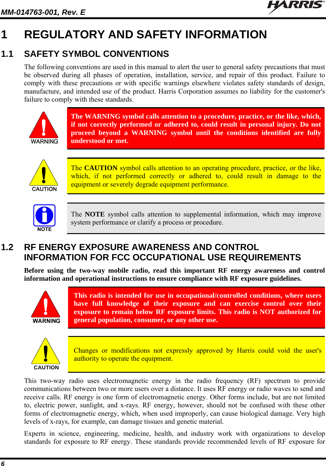
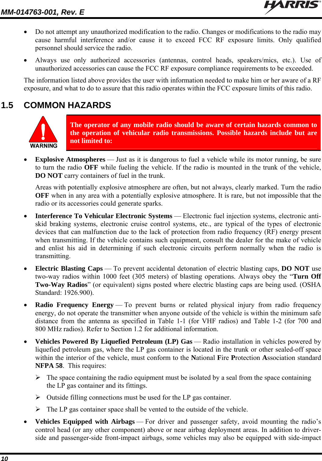
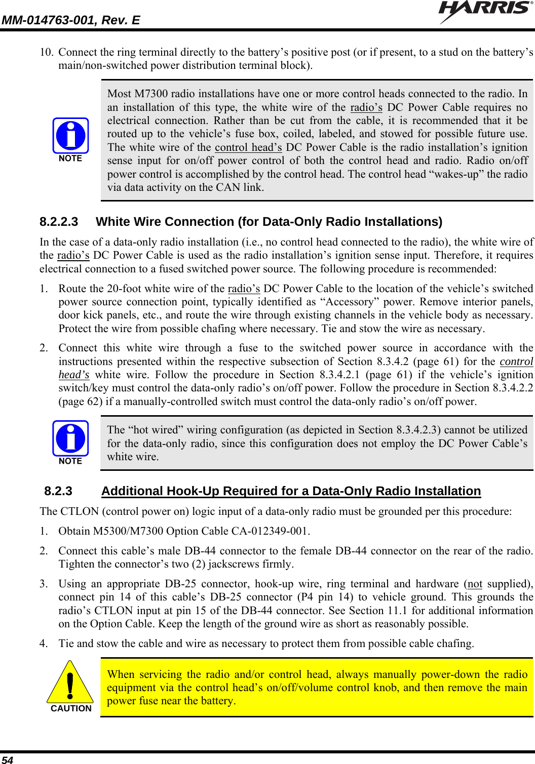
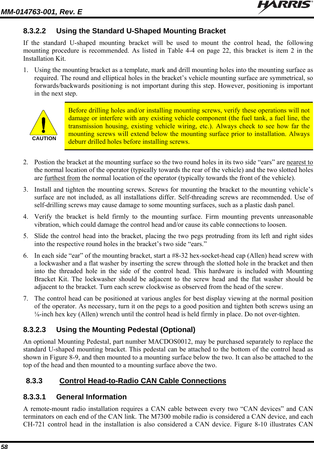
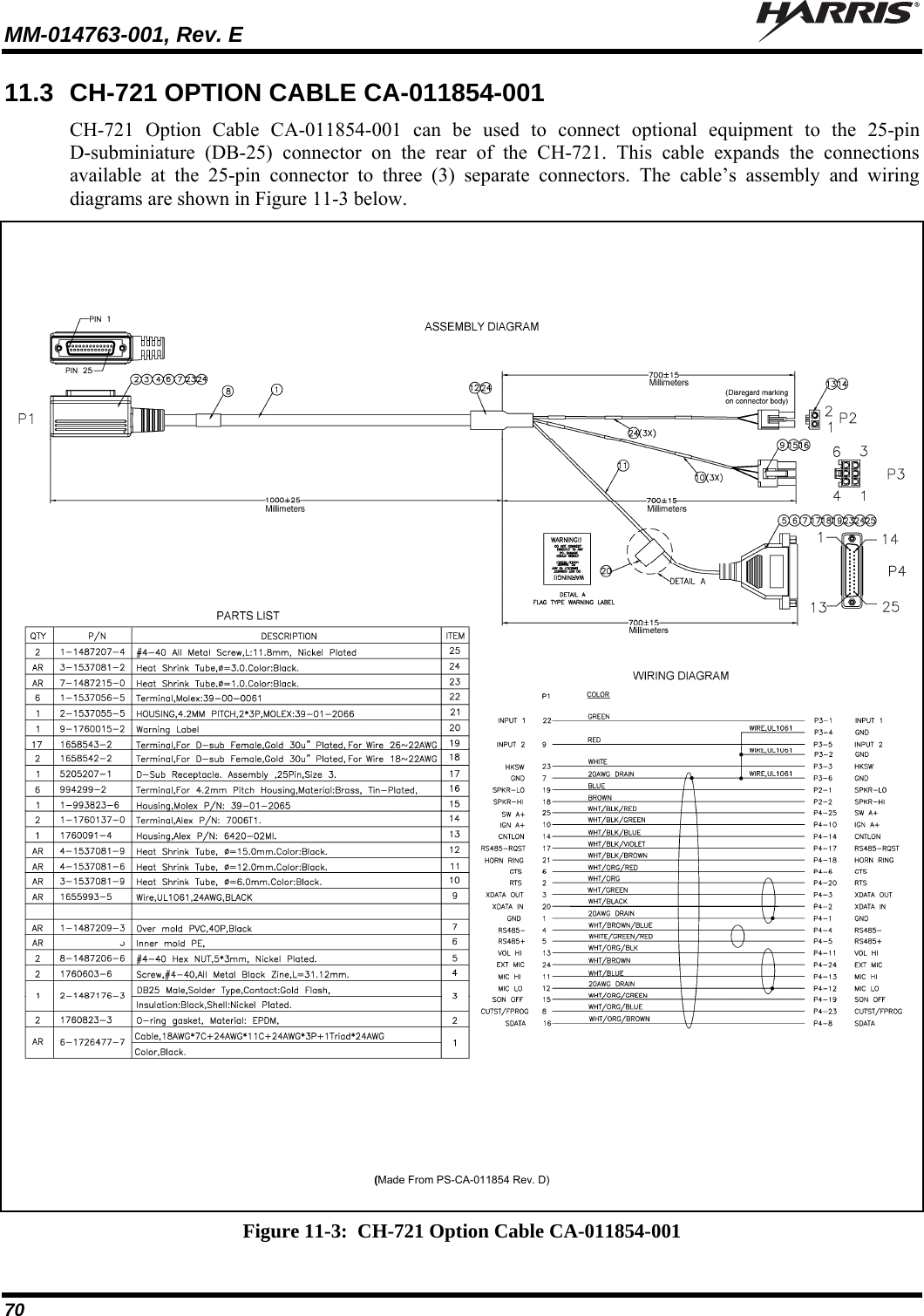
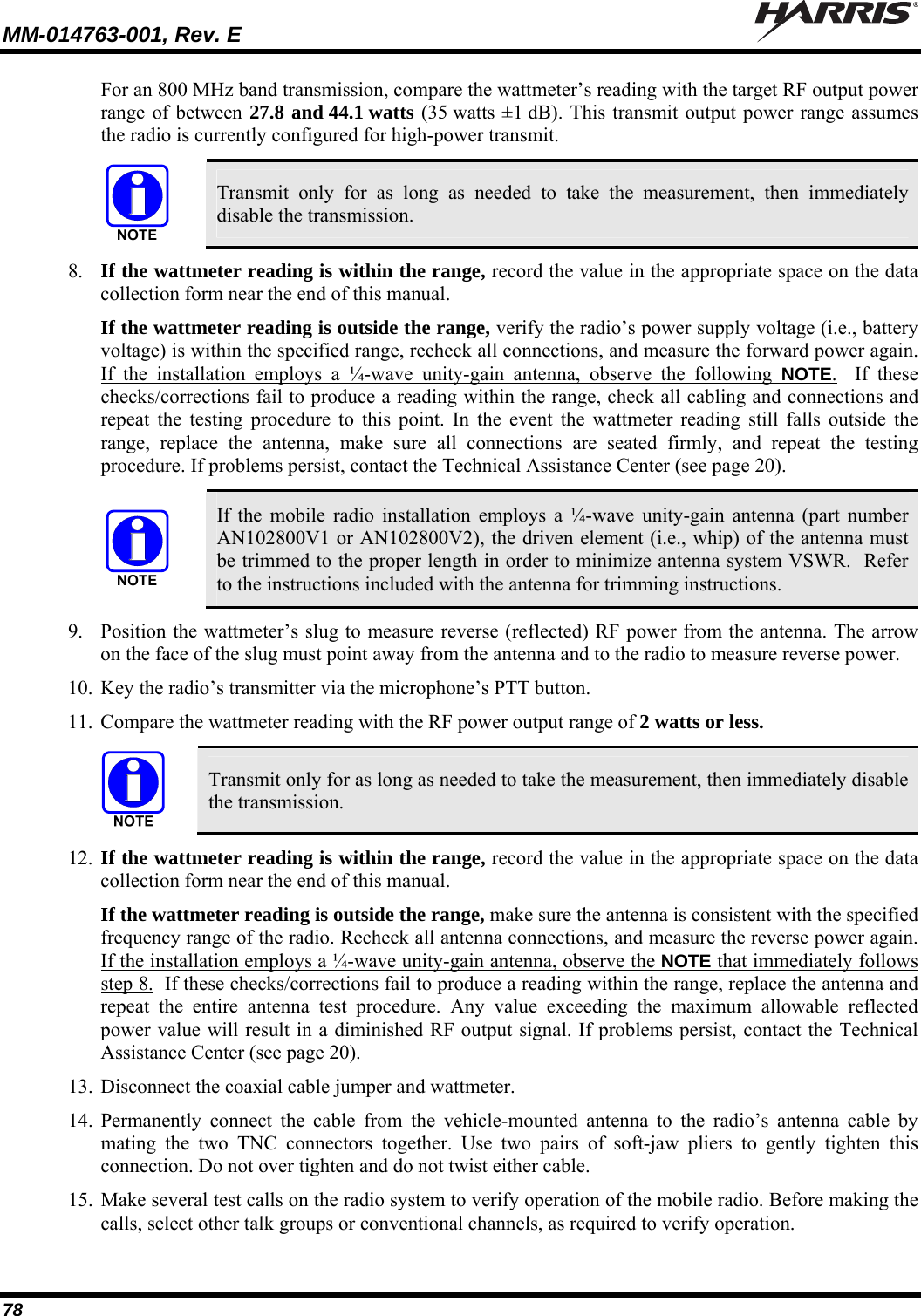
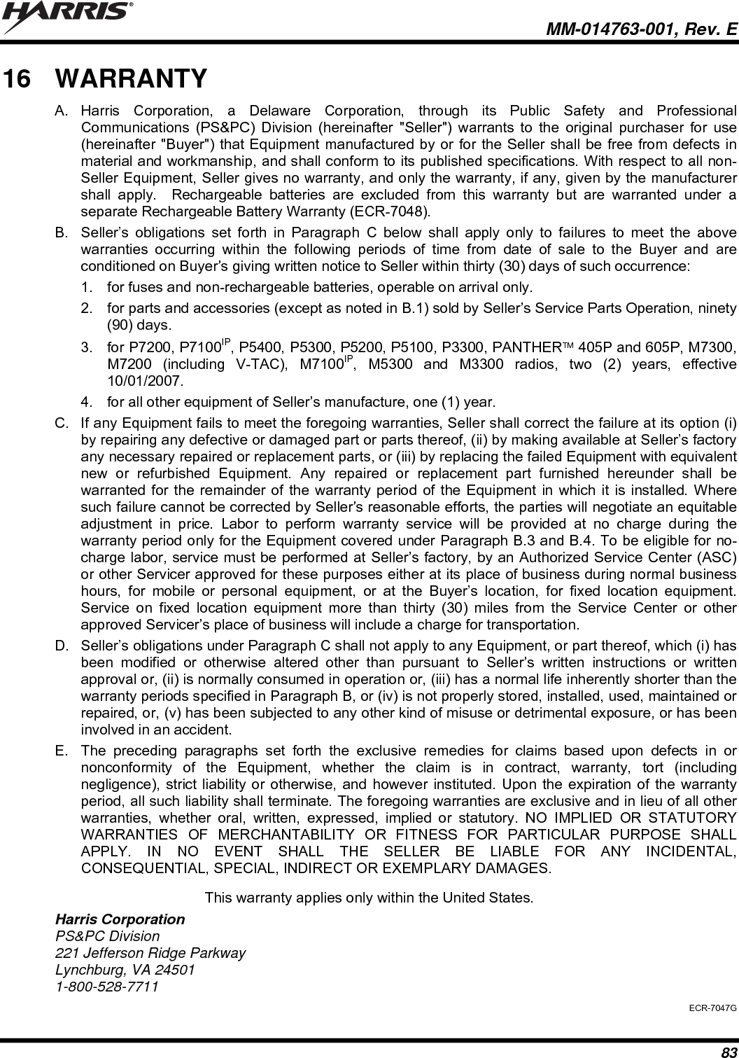
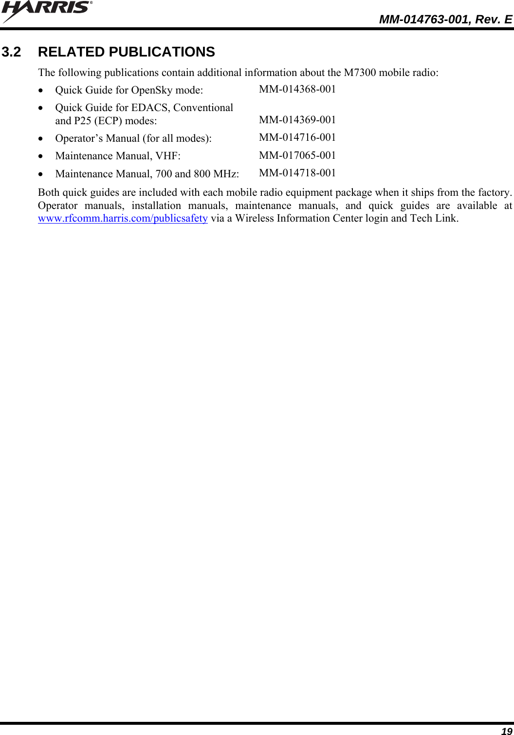
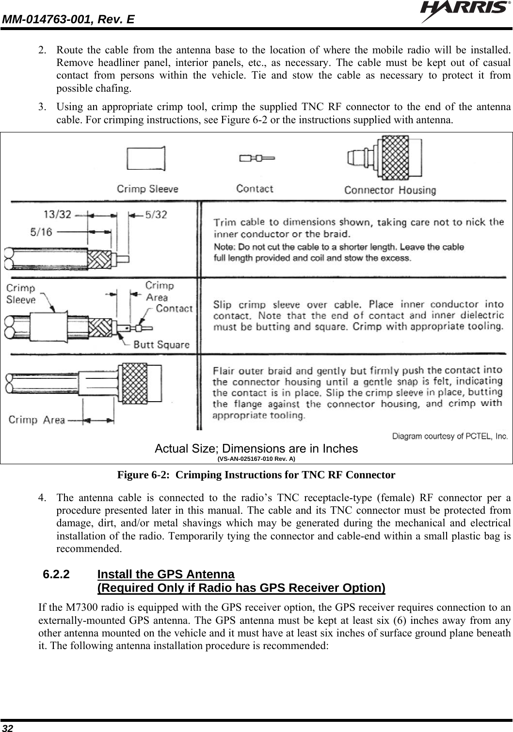
![MM-014763-001, Rev. E 14 Frequency Ranges of 700 & 800 MHz Radio: Receive: 700 MHz Operation: 764 to 767 MHz, 769 to 775 MHz and 773 to 776 MHz (repeater and talk-around operations) [See footnote 2] 800 MHz Operation: 851 to 869 MHz (repeater and talk-around operations) Transmit: 700 MHz Talk-Around Operation: 764 to 767 MHz, 769 to 775 MHz and 773 to 776 MHz 700 MHz Repeater Operation: 794 to 797 MHz, 799 to 805 MHz and 803 to 806 MHz [See footnote 3] 800 MHz Talk-Around Operation: 851 to 869 MHz 800 MHz Repeater Operation: 806 to 824 MHz Transmit RF Output Power of VHF Radio: 136 to 174 MHz RF Channels: 10 to 50 watts (programmable range) Transmit RF Output Power of 700 & 800 MHz Radio: 700 MHz Band RF Channels: 1.5 to 19 watts (programmable range) 800 MHz Band RF Channels: 5 to 35 watts (programmable range) Channel Spacing: 12.5 kHz or 25 kHz or 30 kHz (mode dependent) Voice and Data Communications Modes: Half-Duplex Frequency Stability: ±1.5 ppm with AFC disabled; ±0.5 ppm with AFC Receiver Sensitivity: VHF P25 Mode (TIA-102 Method): -116 dBm minimum at 5% BER (static) VHF EDACS & Conventional Modes: -119 dBm minimum at 12 dB SINAD (25 kHz channels) 700 MHz OTP Mode: -111 dBm minimum at 1% BER (static) 800 MHz OTP Mode: -111 dBm minimum at 1% BER (static) 700 MHz P25 Mode (TIA-102 Method): -116 dBm minimum at 5% BER (static) 800 MHz P25 Mode (TIA-102 Method): -116 dBm minimum at 5% BER (static) 700 MHz EDACS Mode: -119 dBm minimum at 12 dB SINAD 800 MHz EDACS Mode: -118 dBm minimum at 12 dB SINAD Receiver Intermodulation Rejection: 77 dB typical Audio Frequency Response: 300 to 3000 Hz (transmit and receive) Microphone Input Sensitivity: 82 28 mV rms (typical) Microphone Maximum Input Level: 2500 mV peak-to-peak Microphone Input Impedance: 600 ohms) Microphone Audio Frequency Response: 0.5 dB from 100 Hz to 3000 Hz Microphone Connector: 17-pin Conxall-style flush-mount thumbscrew-locking connector located on front panel of control head Microphone Types Available: Standard, DTMF, and Noise-Canceling 2 764 to 767 MHz and 773 to 776 MHz per old FCC 700 MHz band plan. 769 to 775 MHz added August 30, 2007 by new FCC 700 MHz band plan. 3 764 to 767 MHz, 773 to 776 MHz, 794 to 797 MHz and 803 to 806 MHz per old FCC 700 MHz band plan. 769 to 775 MHz and 799 to 805 MHz added August 30, 2007 by new FCC 700 MHz band plan.](https://usermanual.wiki/HARRIS/TR-0055-E.Manual-1/User-Guide-1174092-Page-14.png)
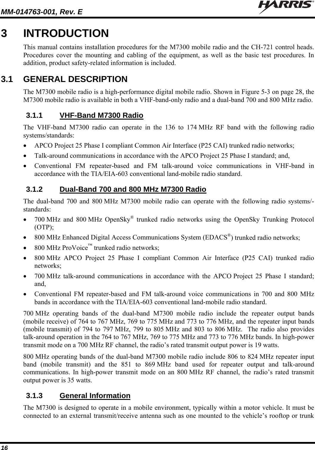

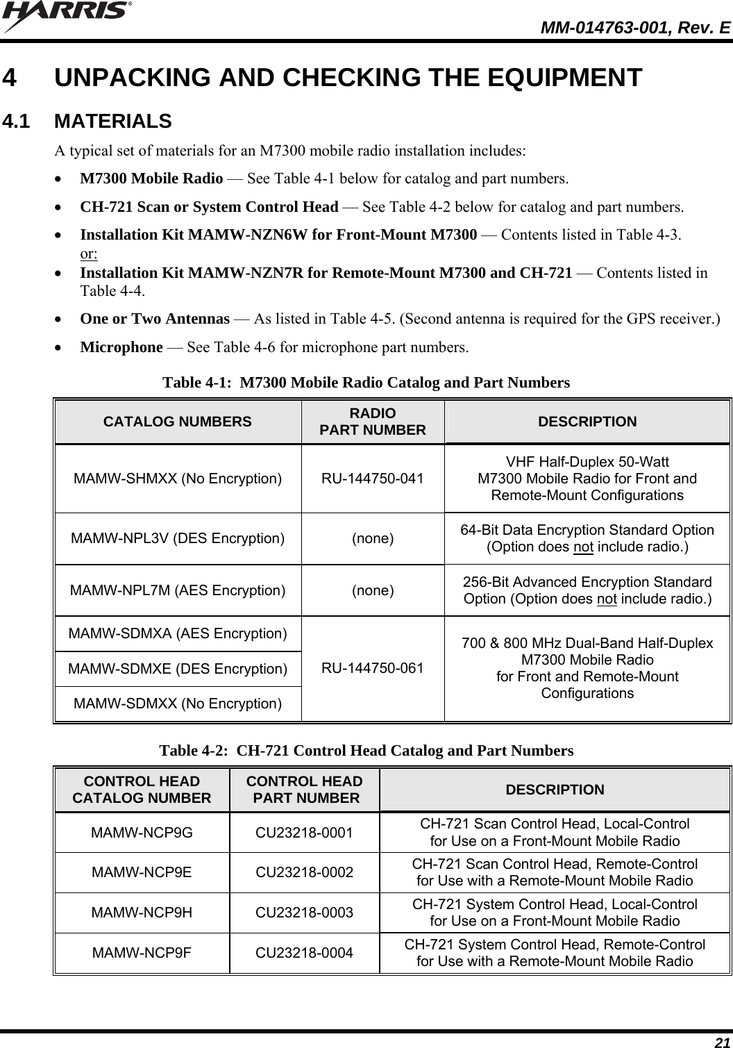
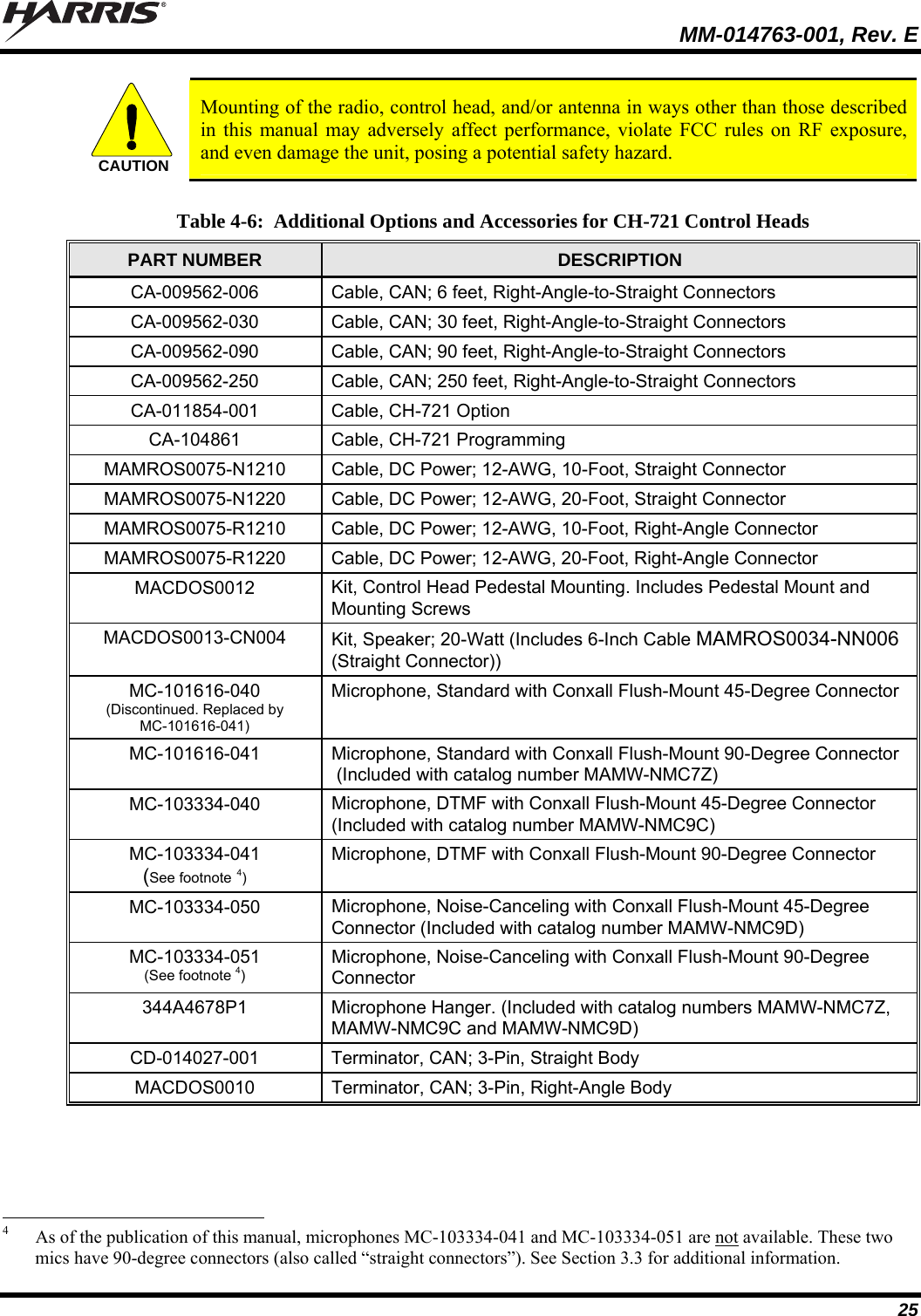
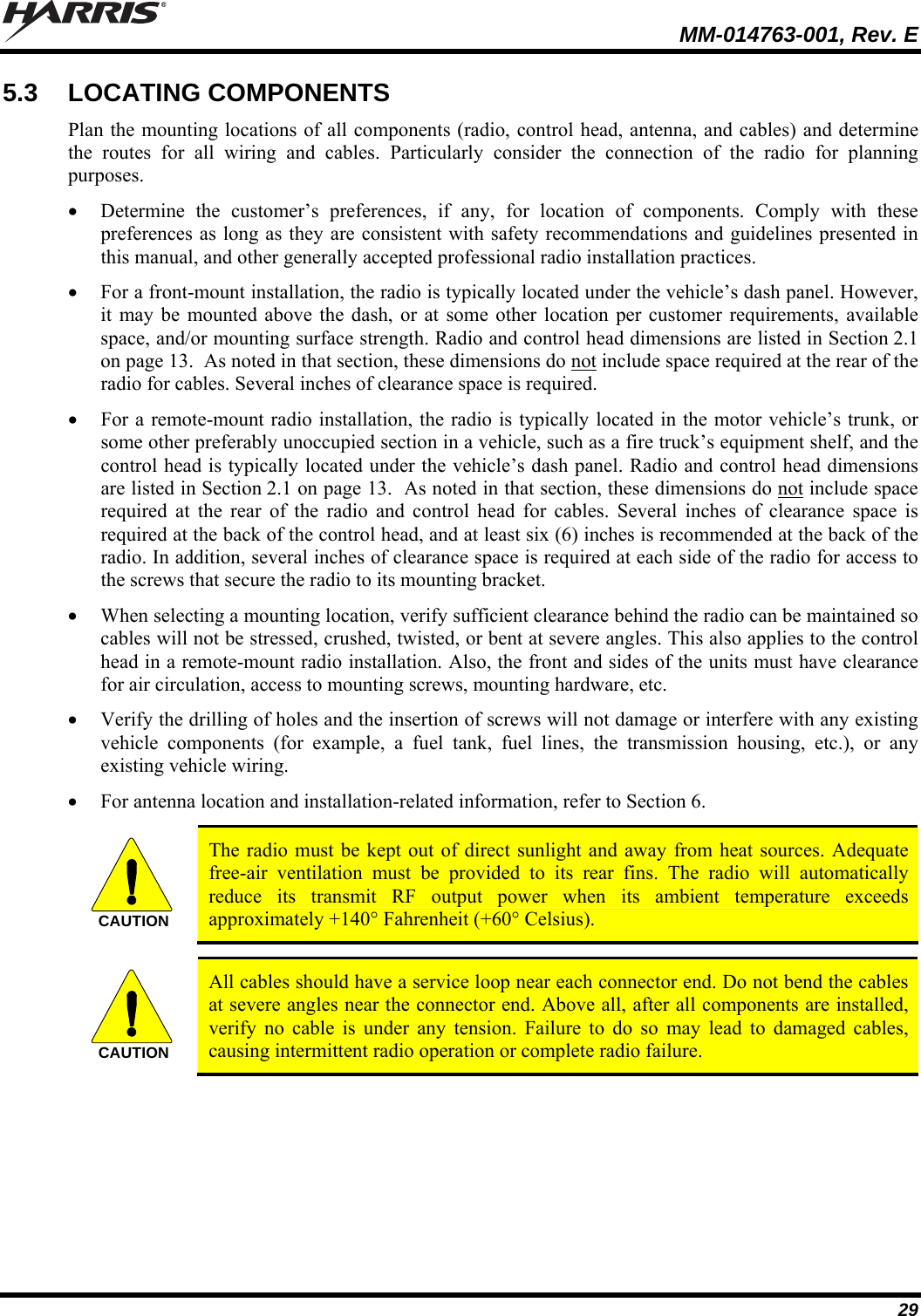
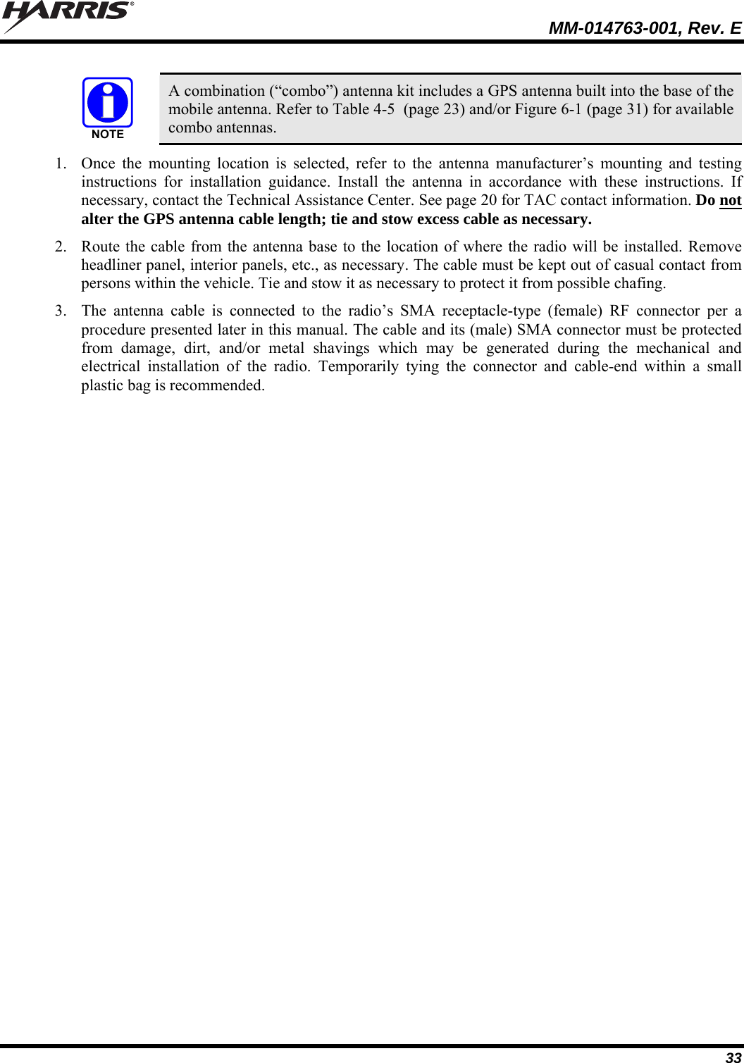
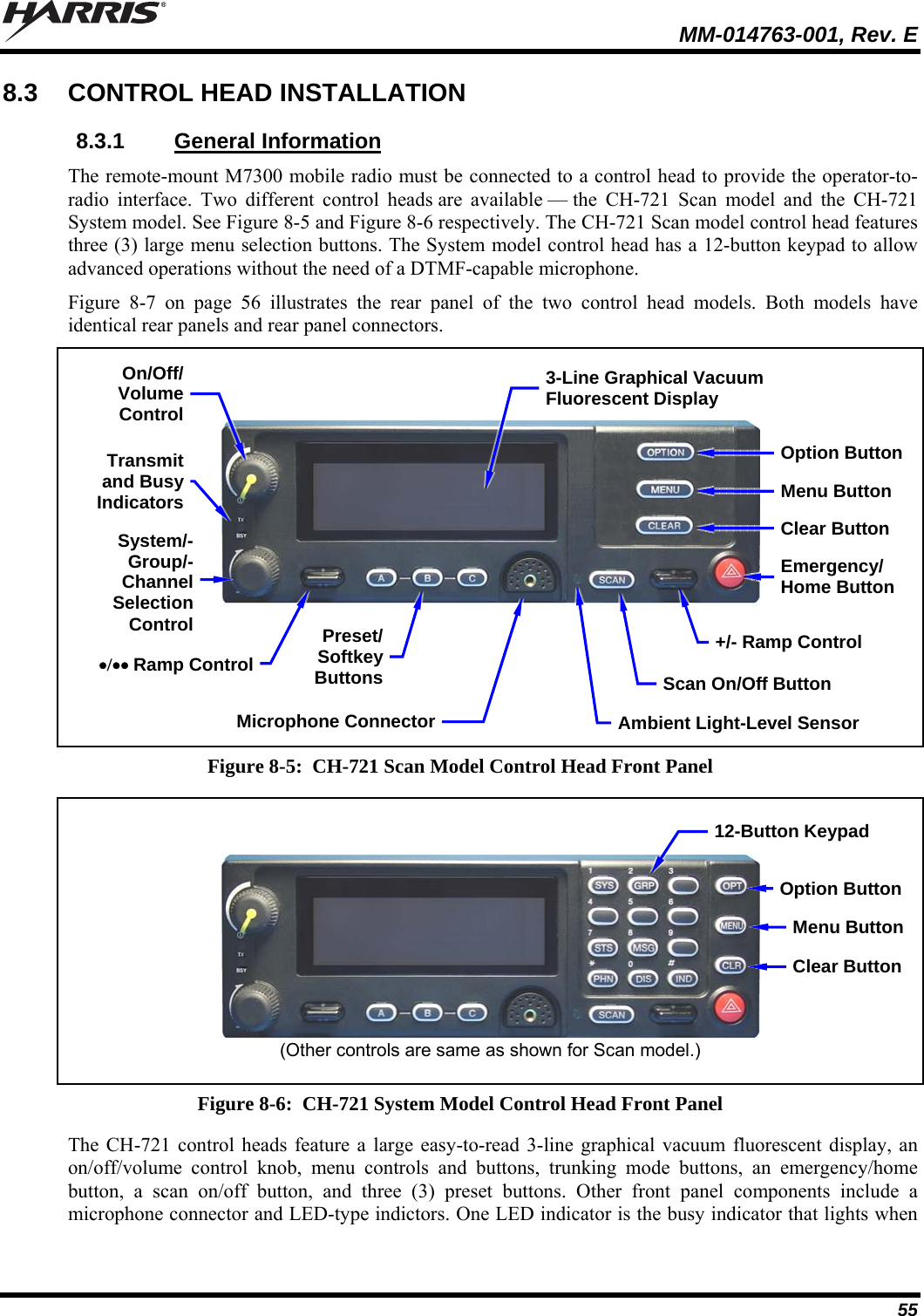
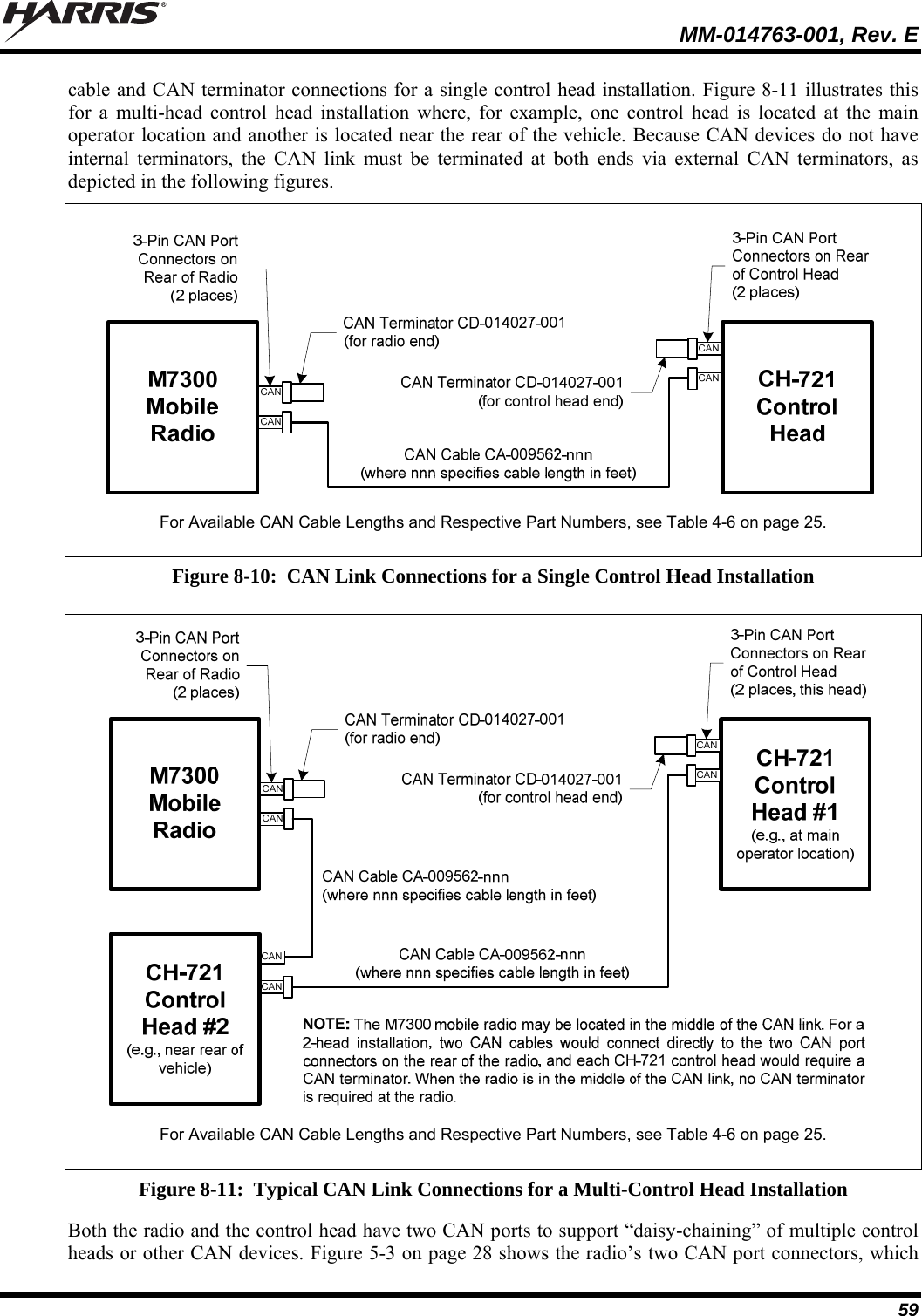
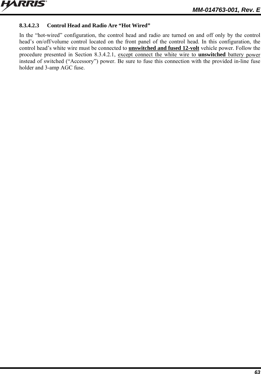
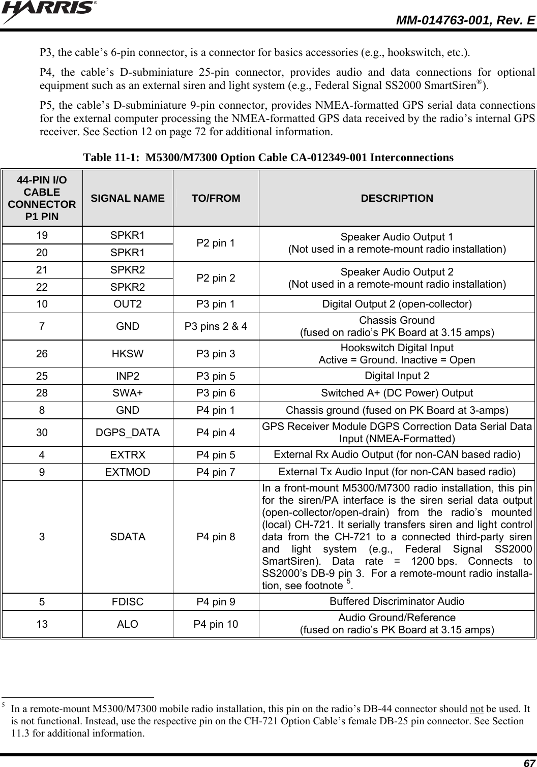
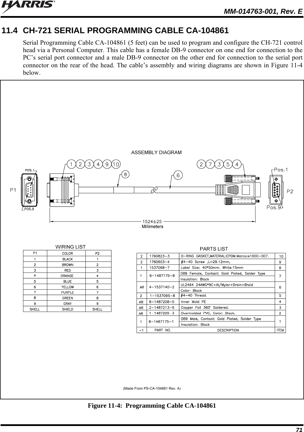
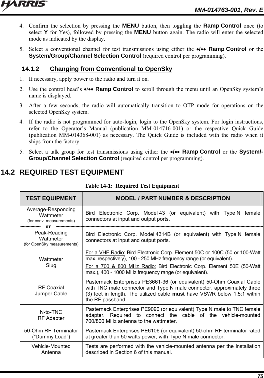
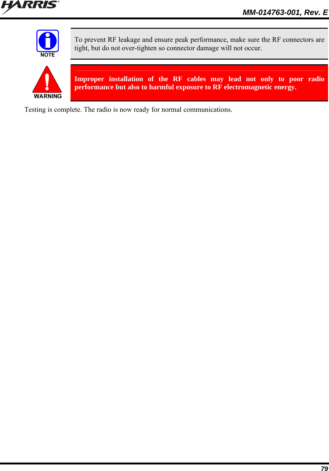
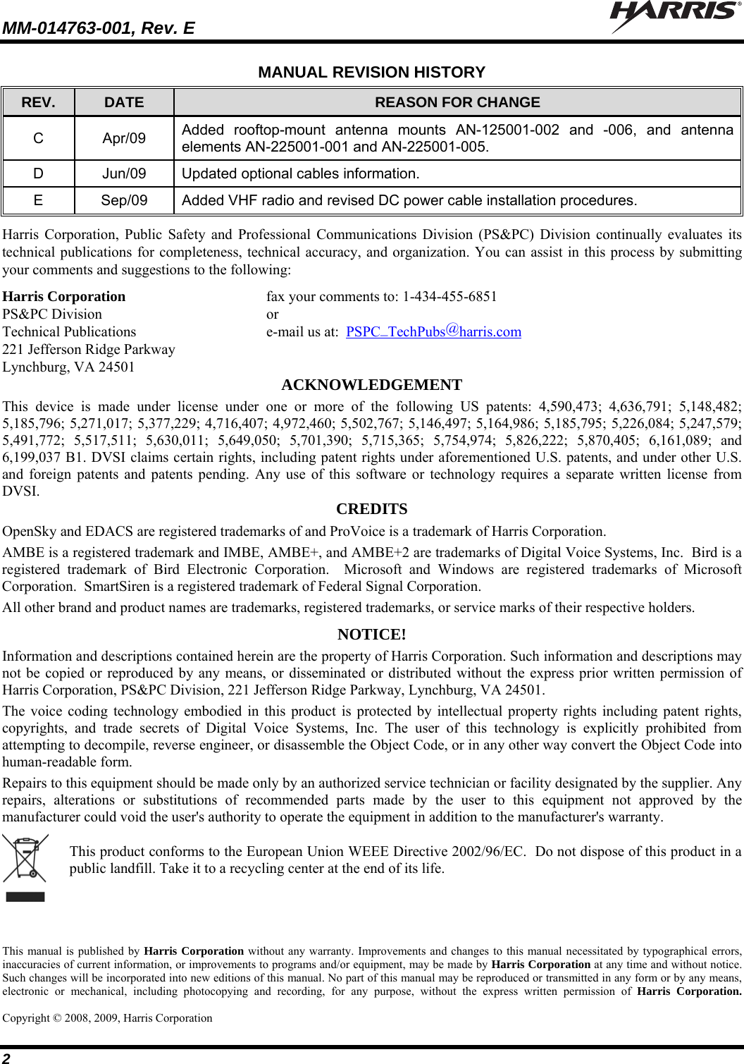
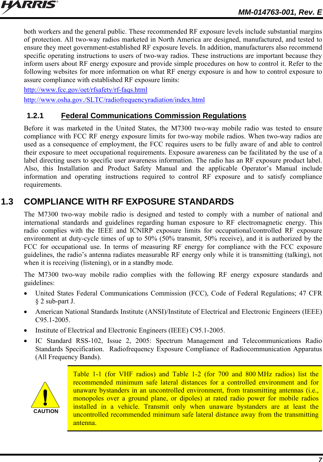
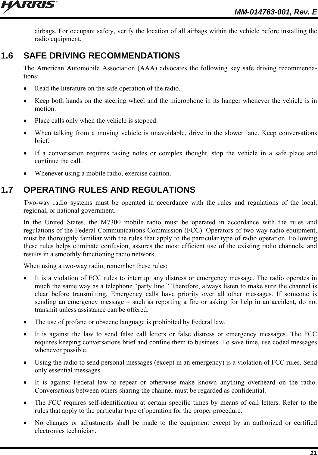
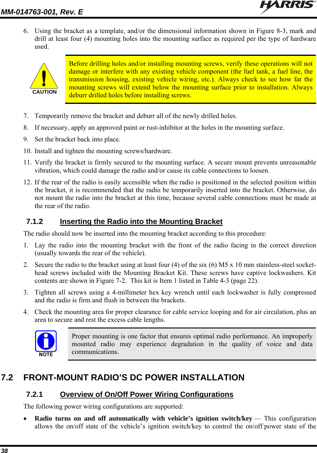
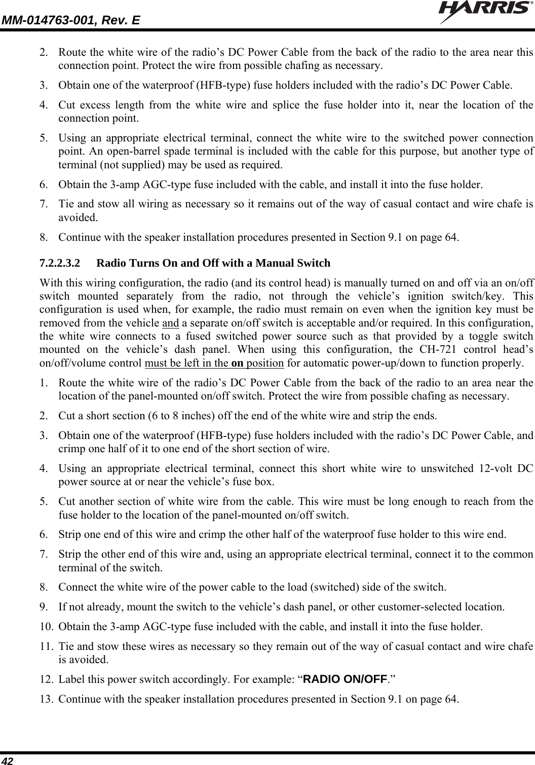
![MM-014763-001, Rev. E 37 TOP VIEW SIDE VIEW (Dimensions in Inches) FRONT/REAR VIEW (Dimensions in Inches) (Made From KBT0310B) Figure 7-3: Mounting Bracket FM101319V1 (Marked KTB0310) Dimensions [for Front-Mount M7300 Mobile Radio (Radio Not Shown)] 3. If the mounting surface is not flat (such as the top of a transmission hump), construct a suitable mounting wedge as necessary, and attach the wedge to the surface using an approved attachment method. Never mount the bracket directly to a non-flat surface. 4. On the mounting surface, mark the selected location for the bracket, and then remove the radio from the bracket. 5. Clean and remove any foreign material from the mounting surface. Bracket-To-Vehicle Screw Holes (11 places)Bracket-To-Radio Screw Holes(10 places,5 each side)](https://usermanual.wiki/HARRIS/TR-0055-E.Manual-1/User-Guide-1174092-Page-37.png)
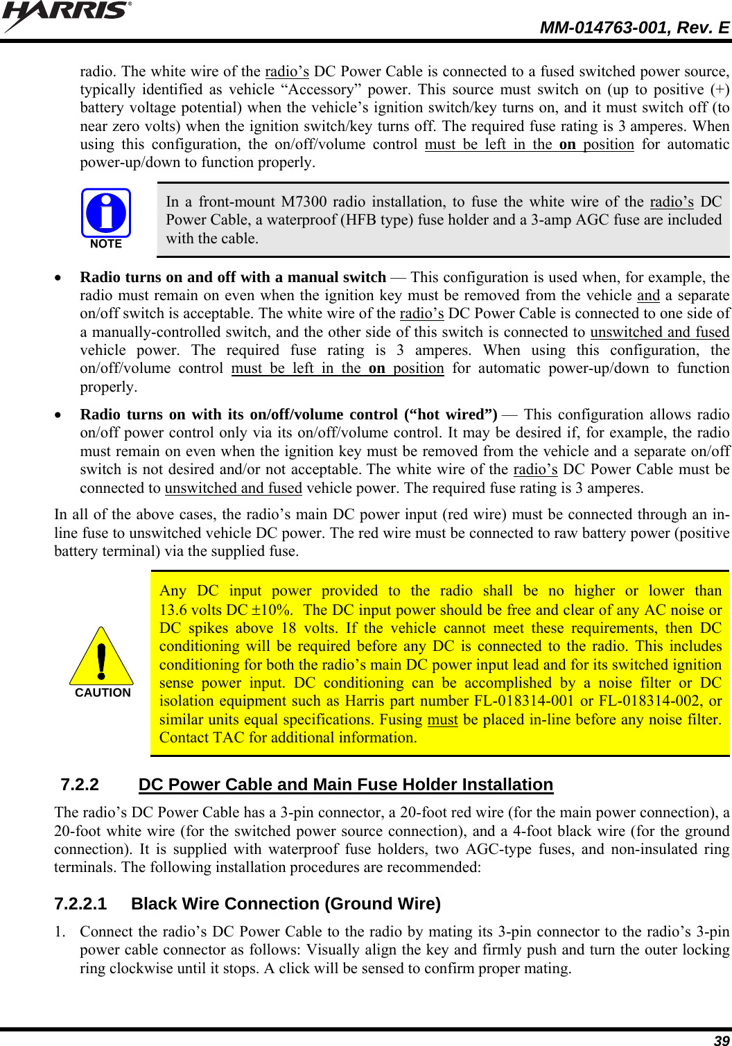
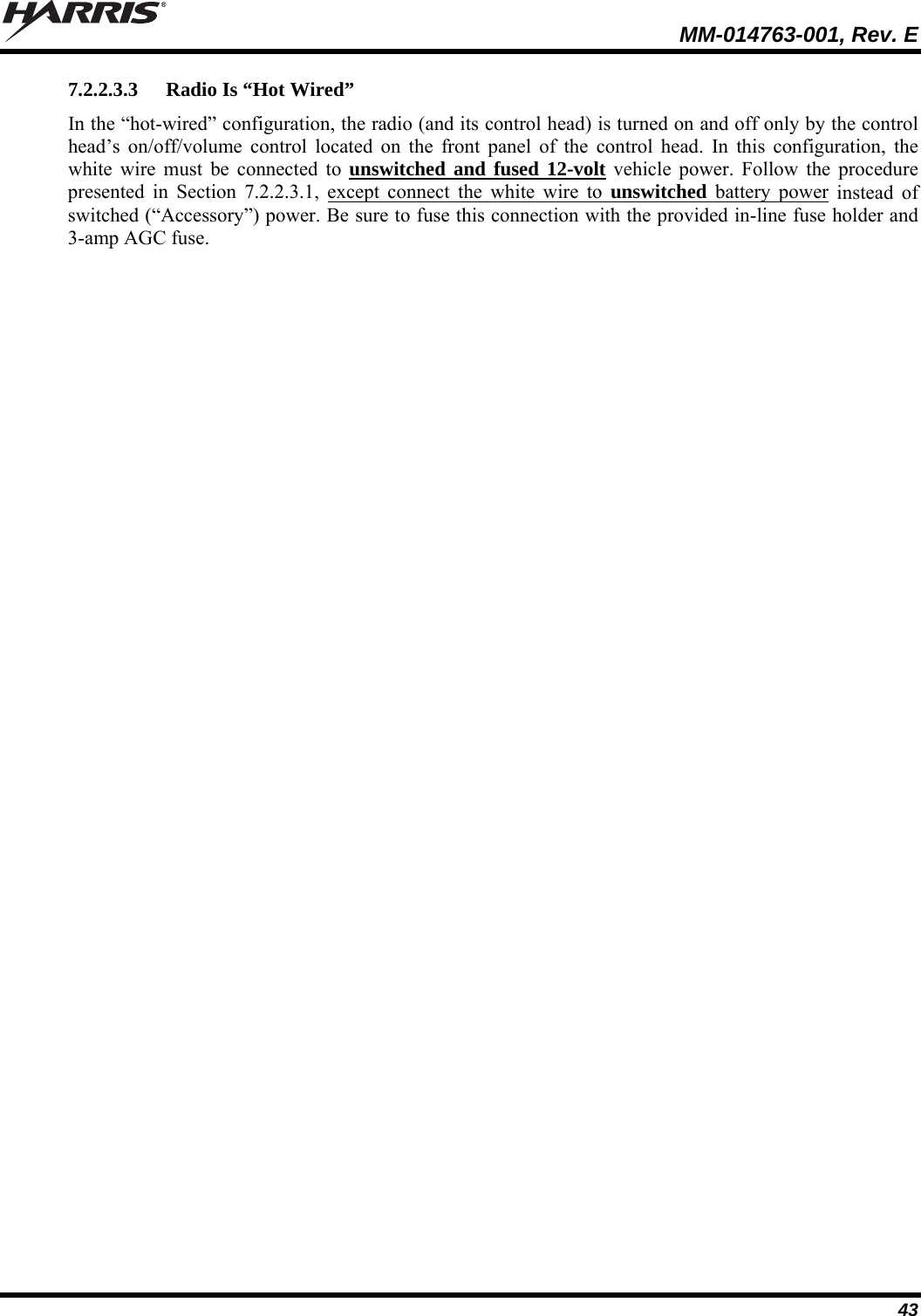
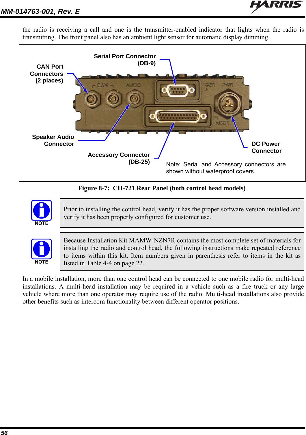
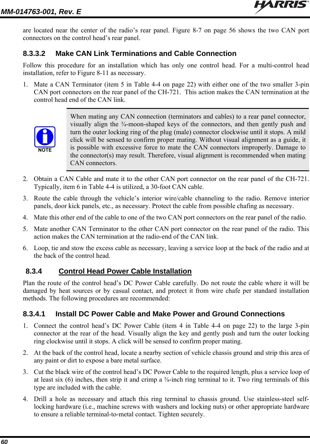
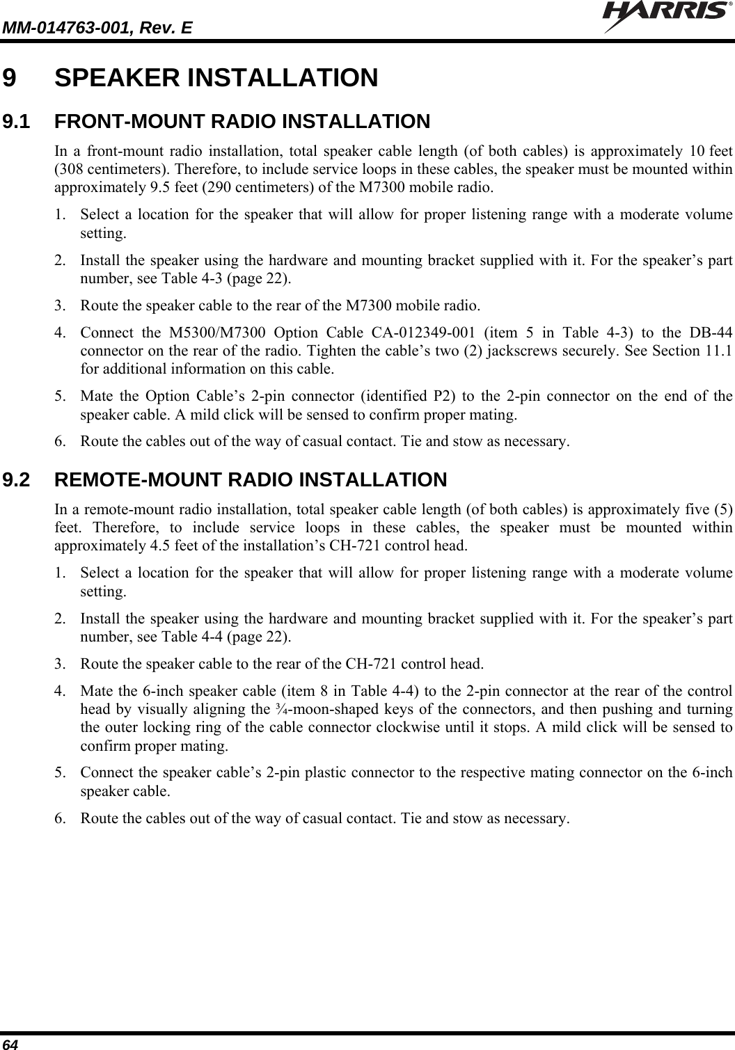
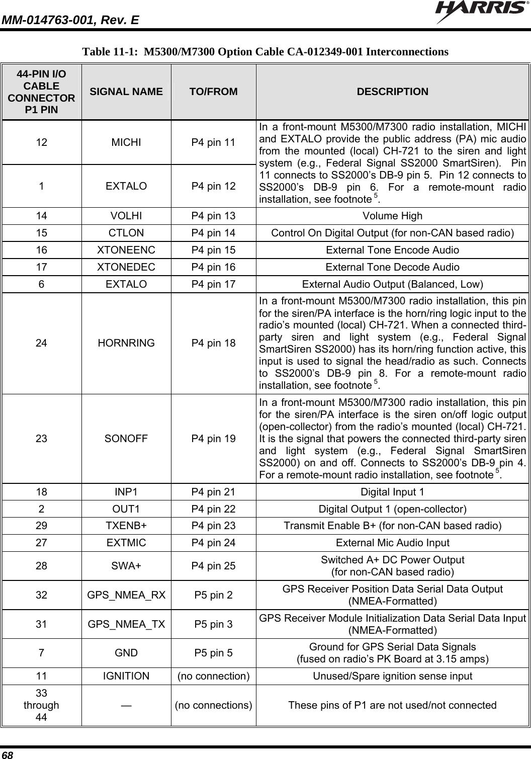
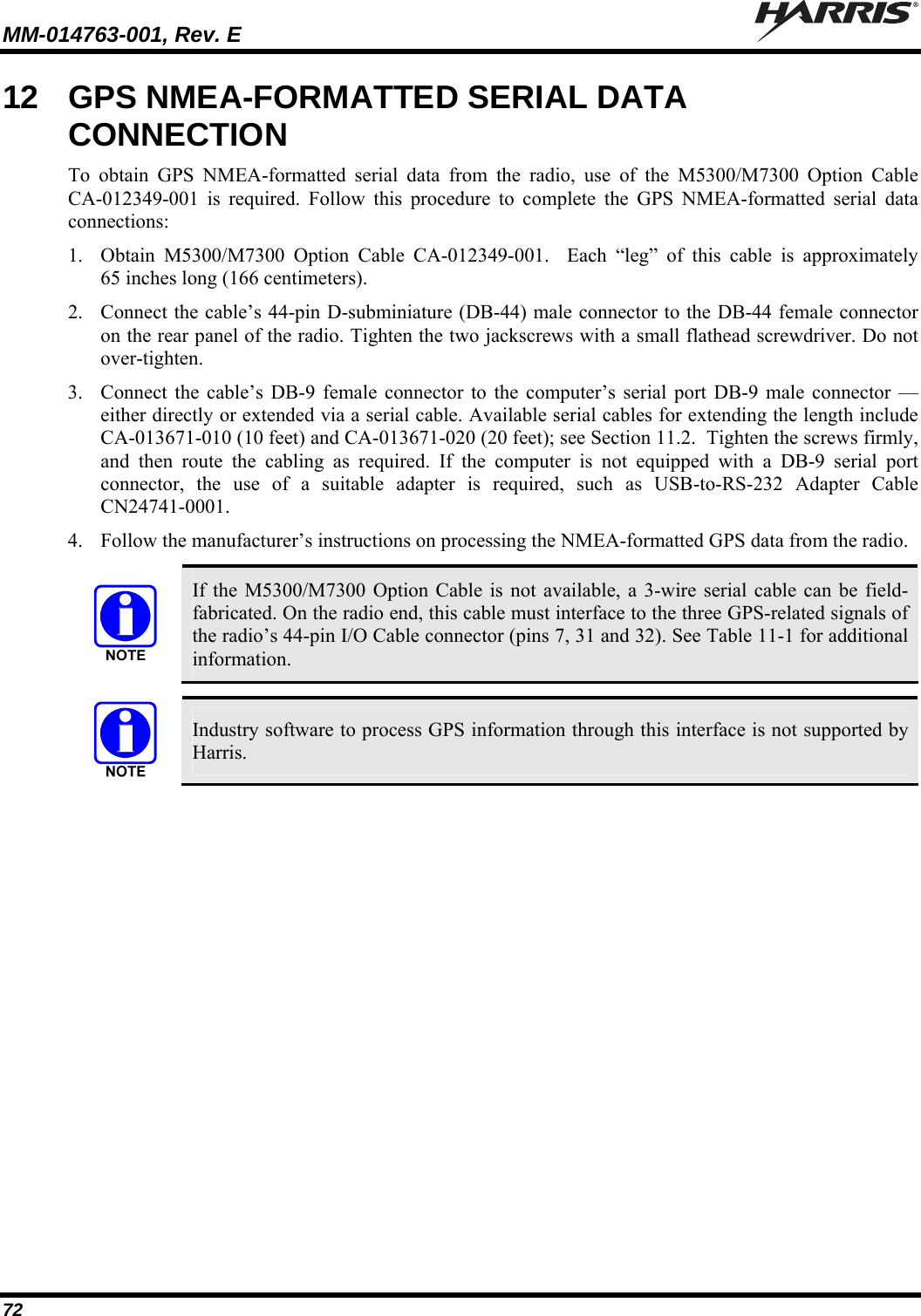
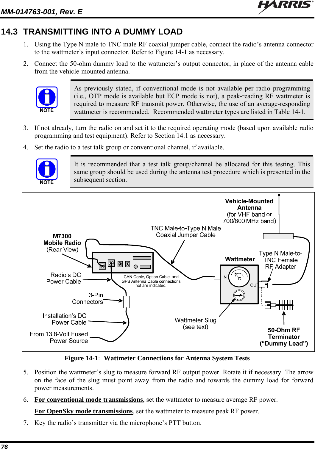
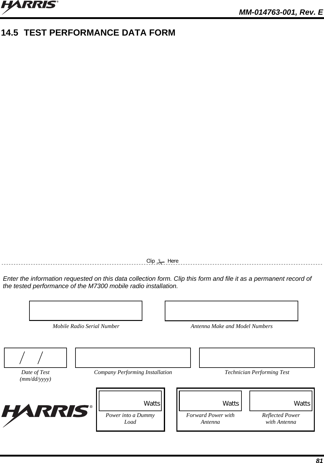
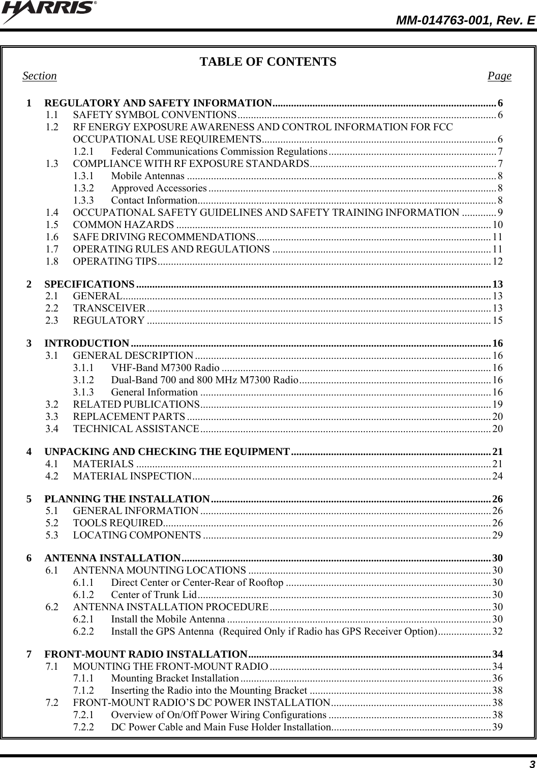
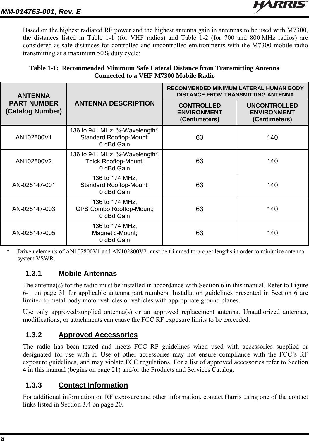
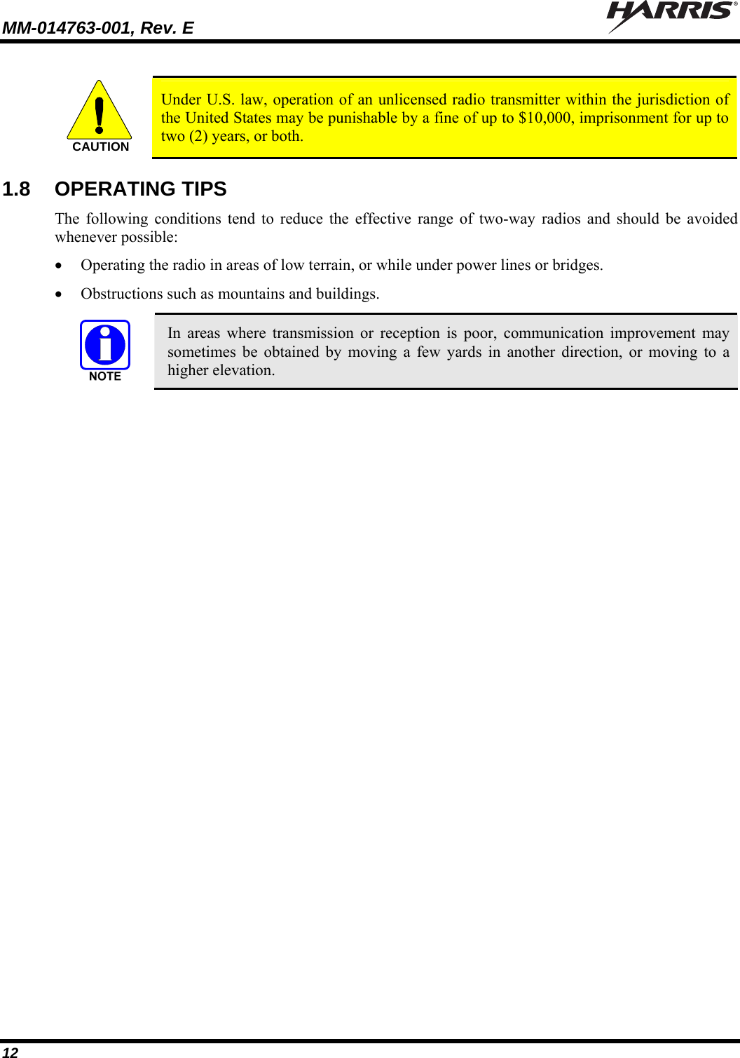
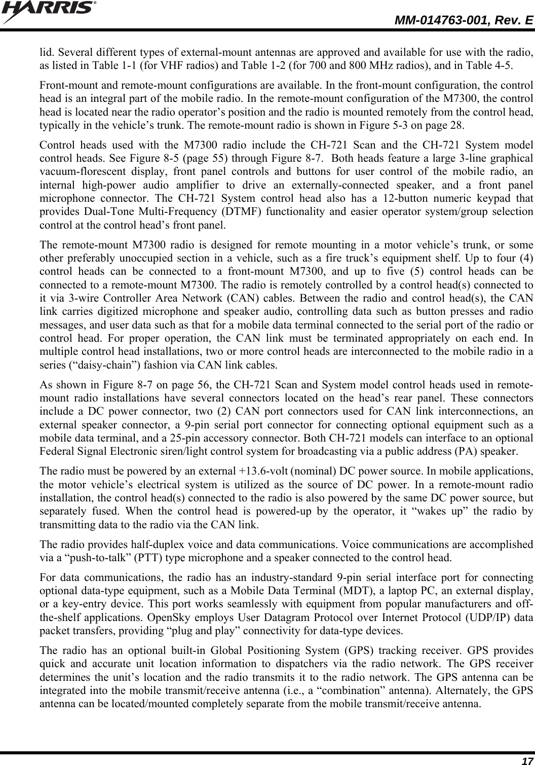
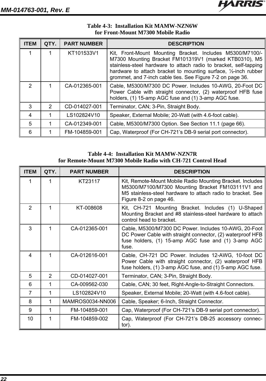
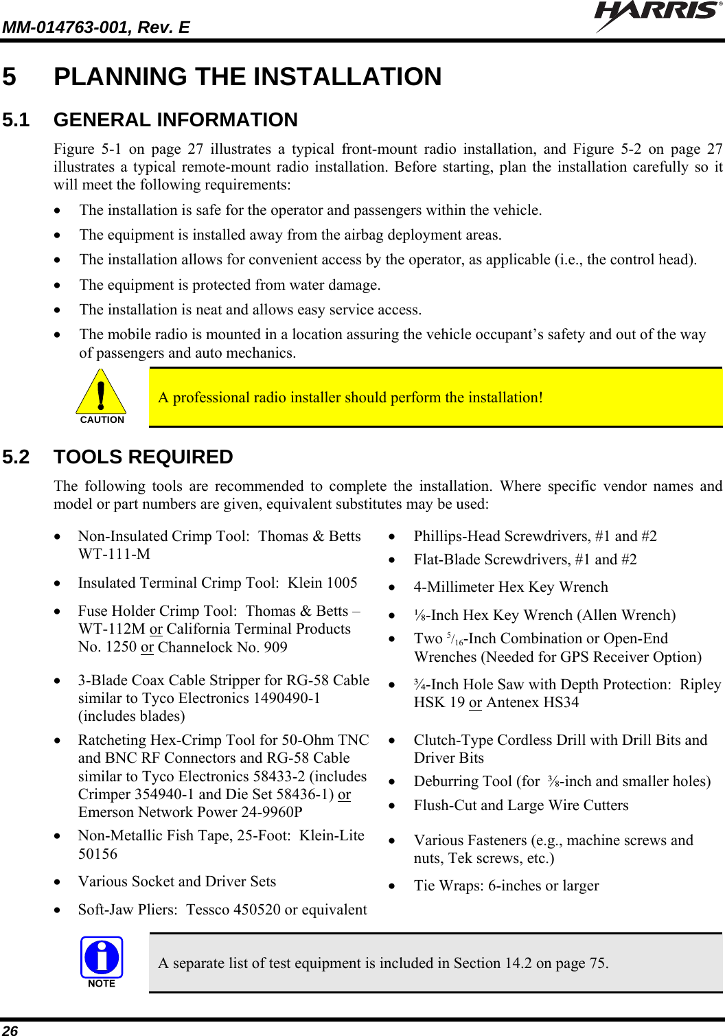
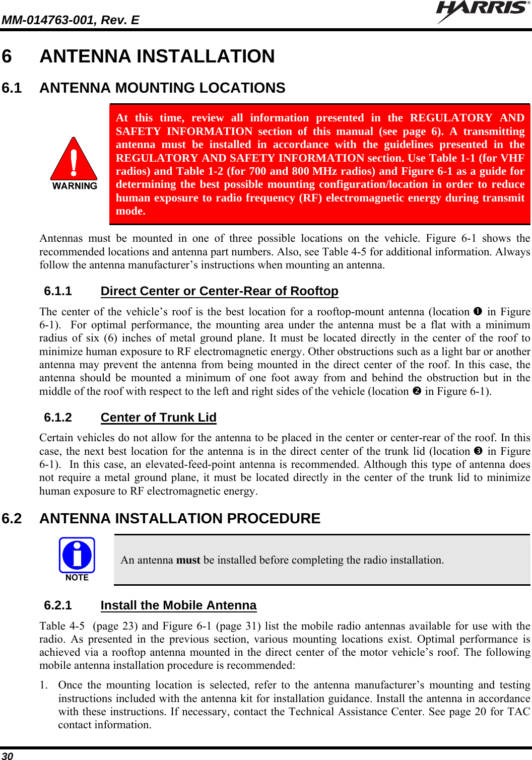
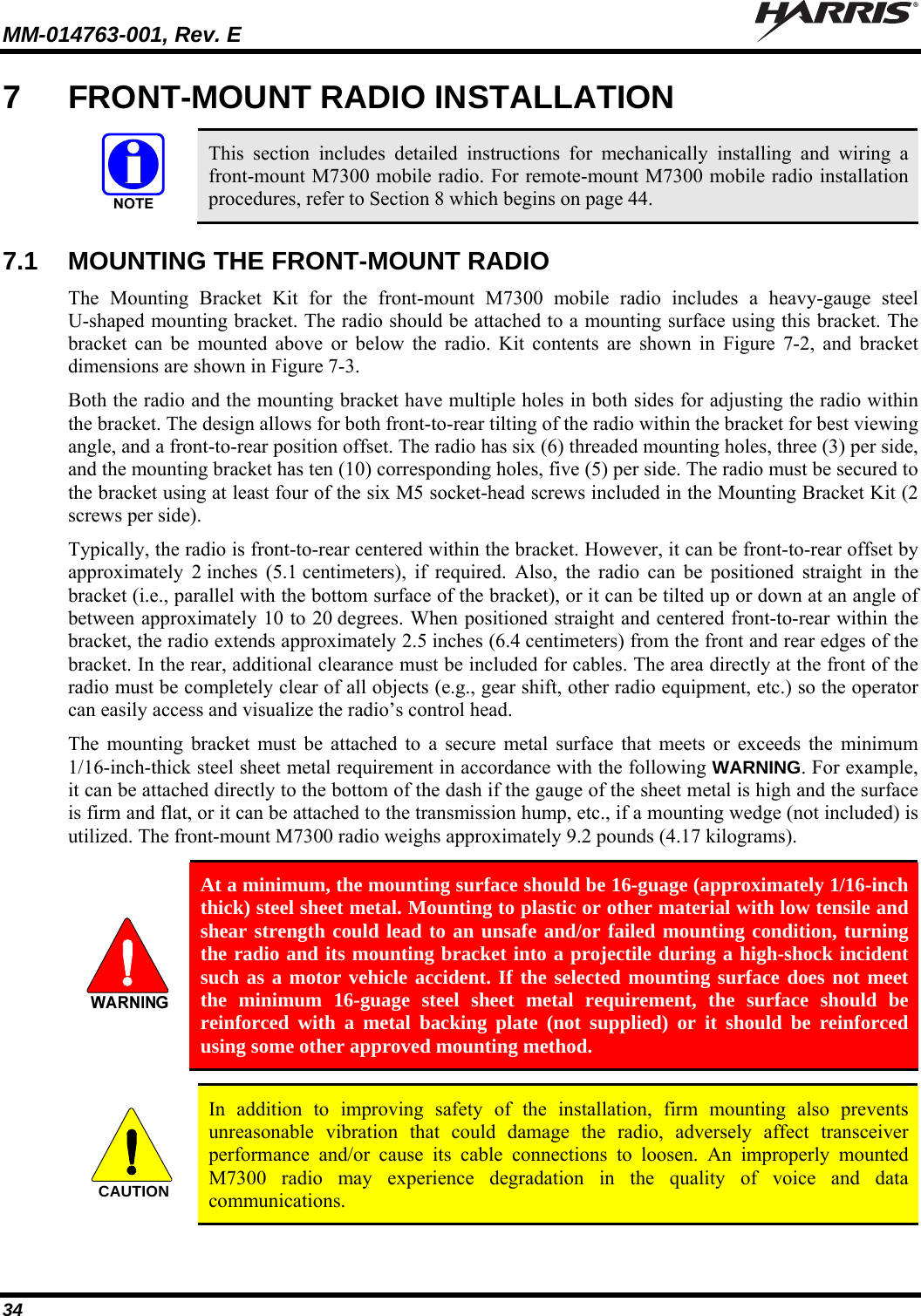
![MM-014763-001, Rev. E 47 5. Install and tighten the mounting screws/hardware. 6. Verify the bracket is firmly secured to the mounting surface. A secure mount prevents unreasonable vibration, which could damage the radio and/or cause its cable connections to loosen. TOP VIEW SIDE VIEW (Dimensions in Inches) FRONT VIEW (Dimensions in Inches) (Made From FM103111 Rev. B) Figure 8-3: Mounting Bracket FM103111V1 Dimensions [for Remote-Mount M7300 Mobile Radio (Radio Not Shown)] Bracket-To-Vehicle Screw Holes (4 places) Bracket-To-Radio Screw Holes(6 places,3 each side)Rear of Bracket Front of Bracket](https://usermanual.wiki/HARRIS/TR-0055-E.Manual-1/User-Guide-1174092-Page-47.png)