HARRIS TR-0055-E M7300 VHF 50W Mobile Radio User Manual Manual 2
HARRIS CORPORATION M7300 VHF 50W Mobile Radio Manual 2
UserManual.wiki
>
HARRIS
>
TR-0055-E User Manual
>
Manual 2
Contents
1.
Manual 1
2.
Manual 2
3.
Manual 3
4.
manual 2
Manual 2
Navigation menu
Upload a User Manual
Namespaces
Wiki Guide
HTML
PDF
Info
Views
User Manual
Discussion / Help
Navigation
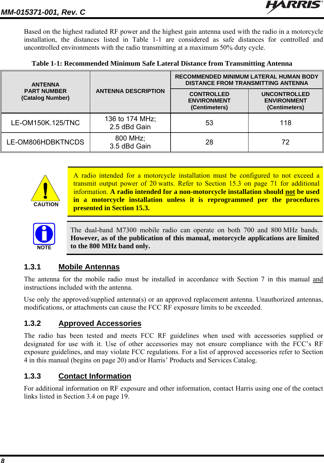
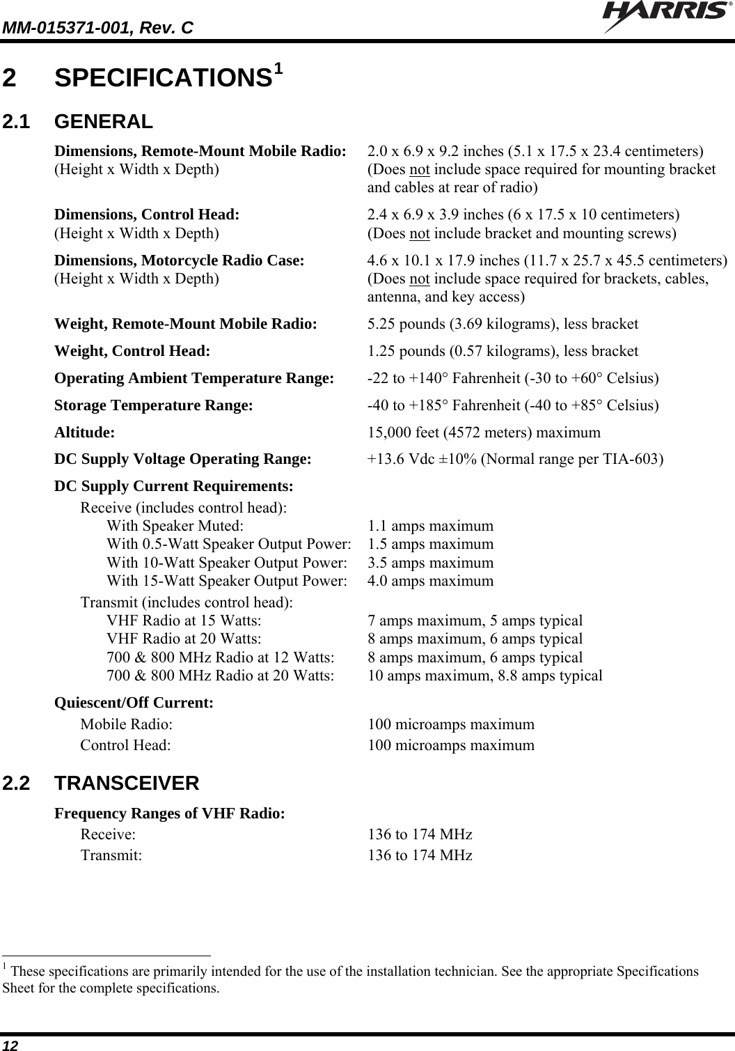
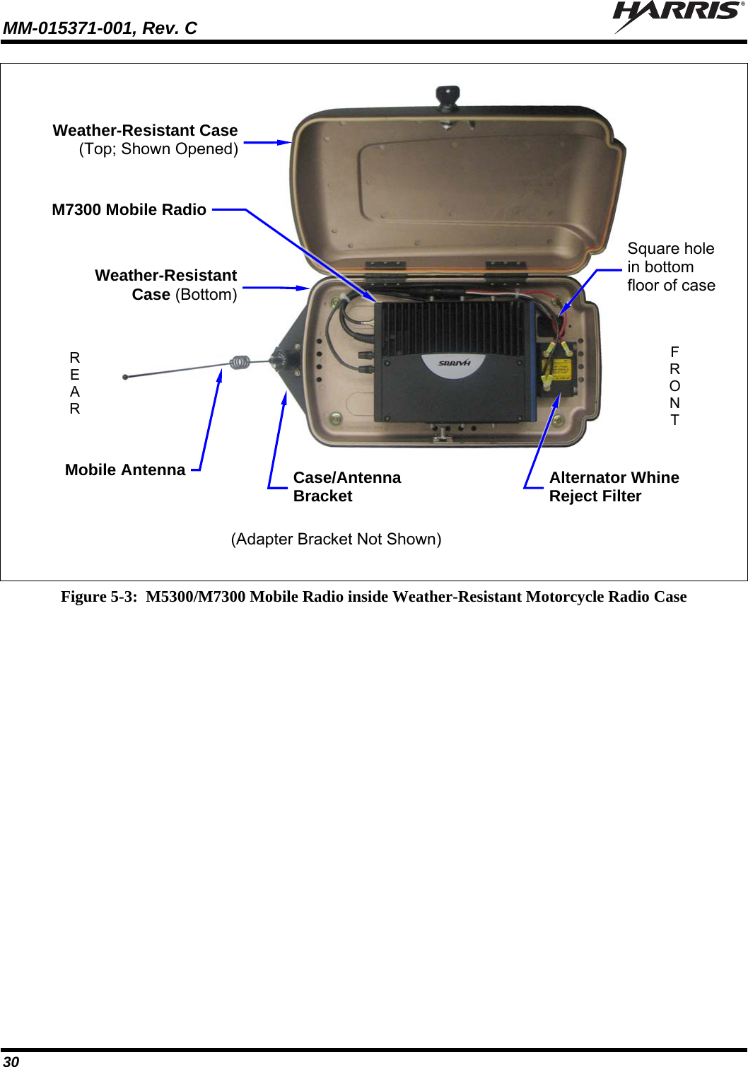
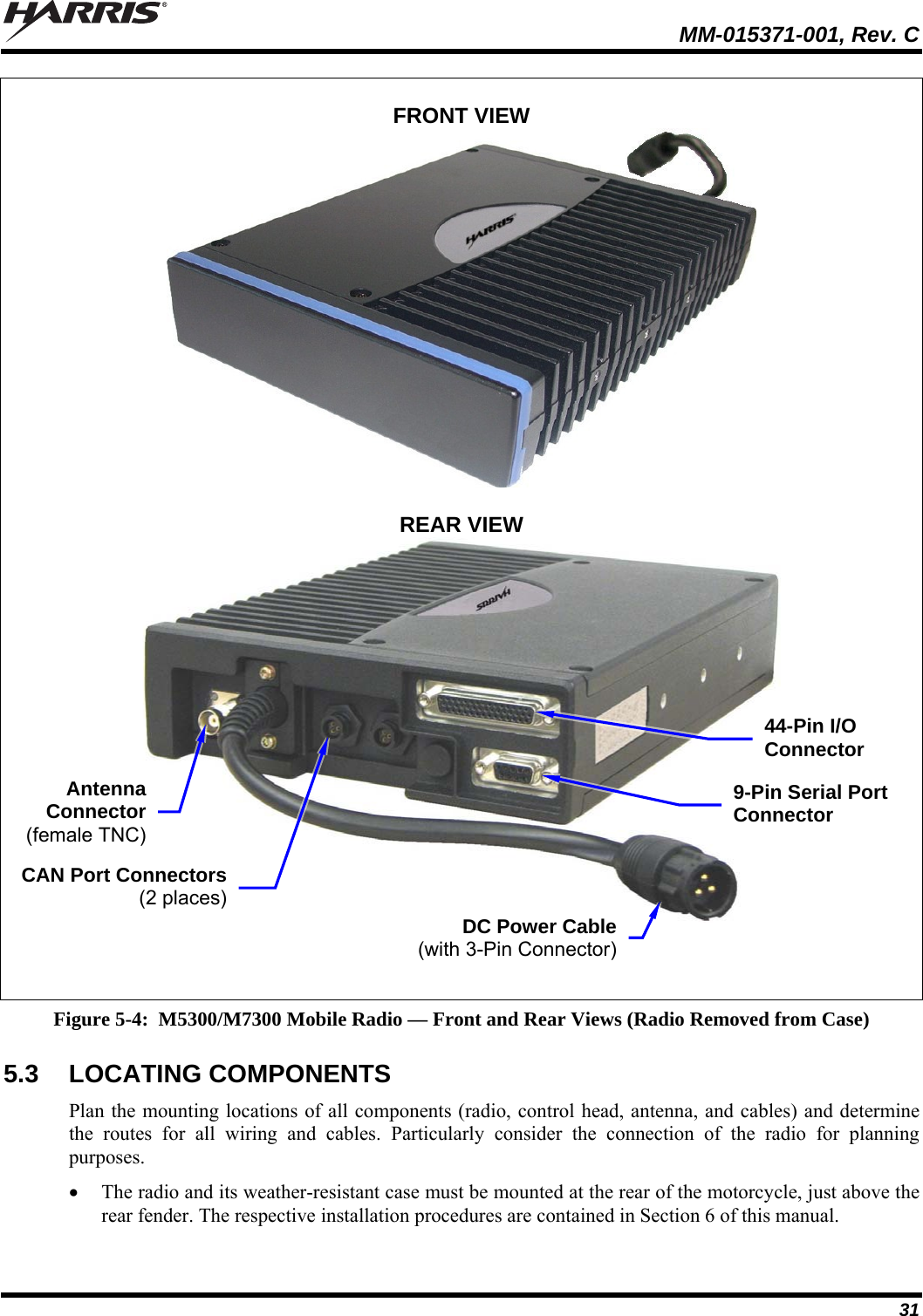
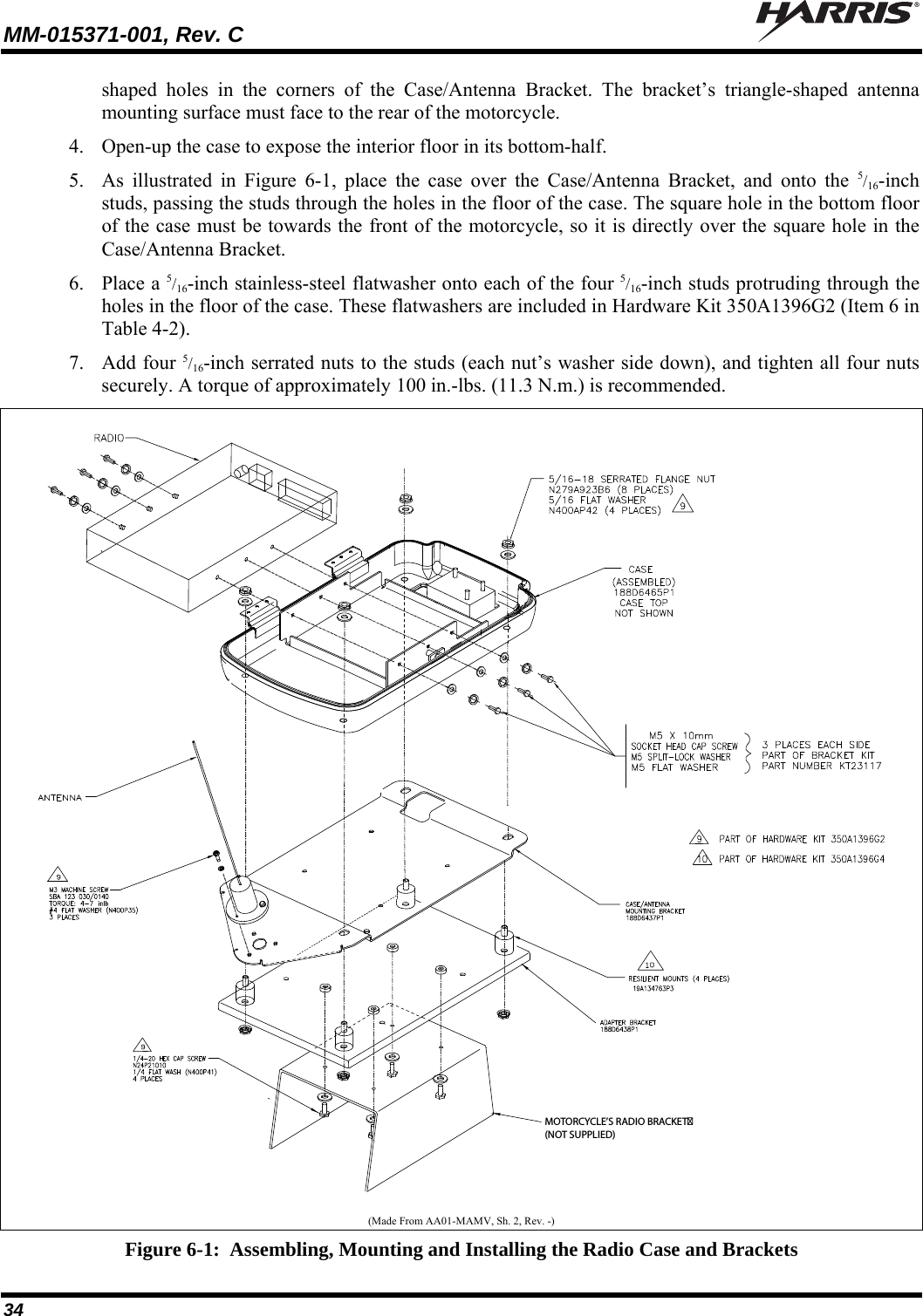
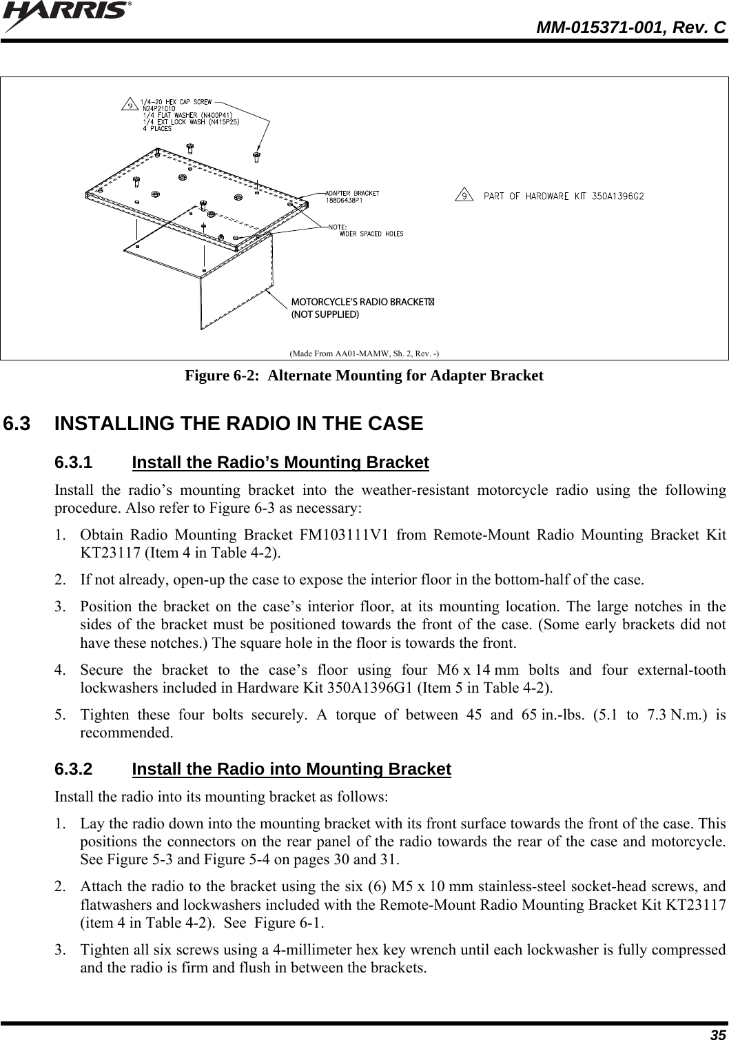
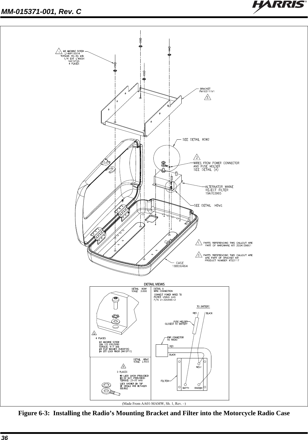
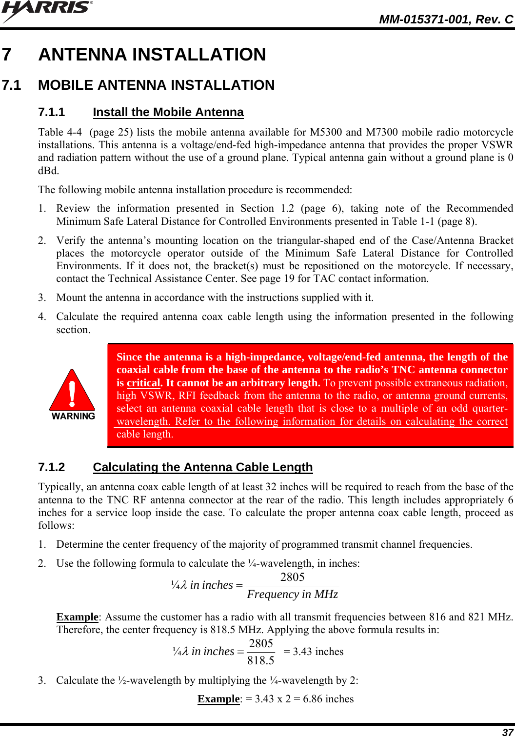
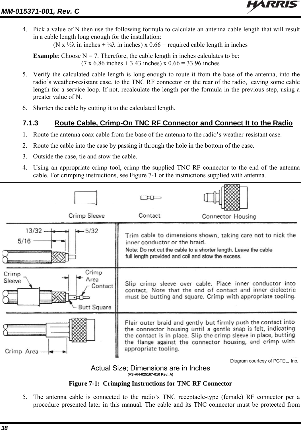
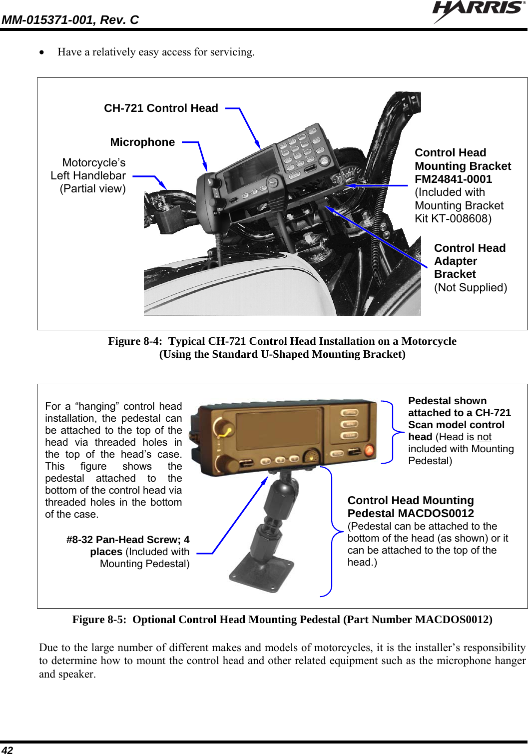
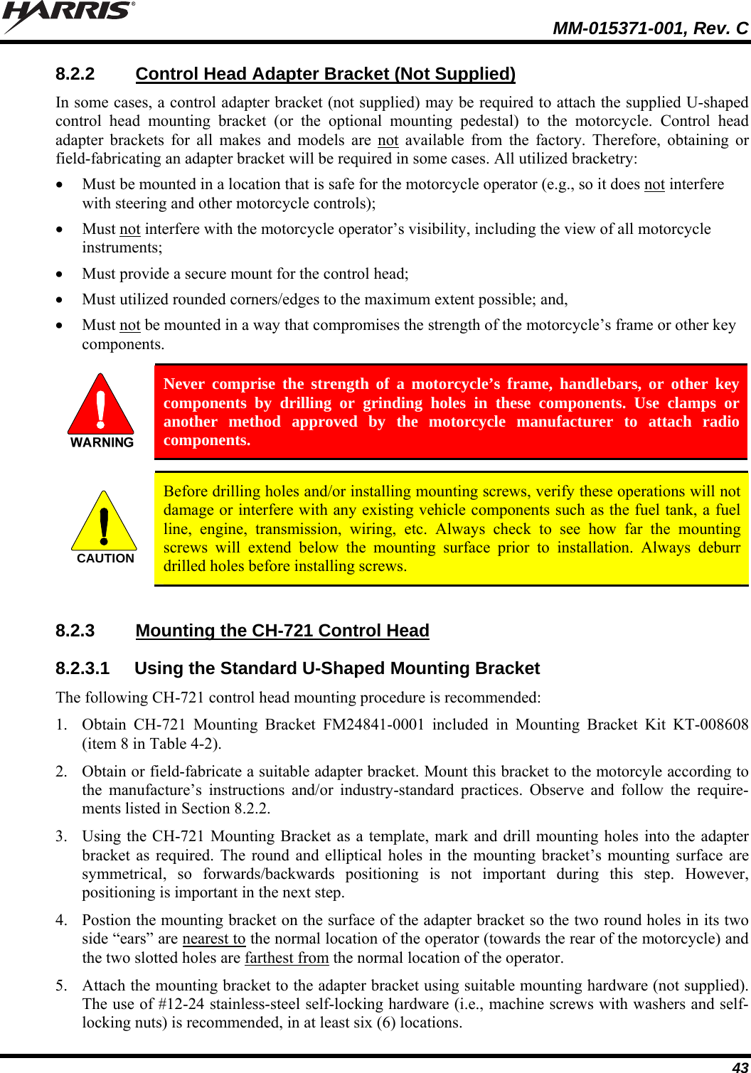
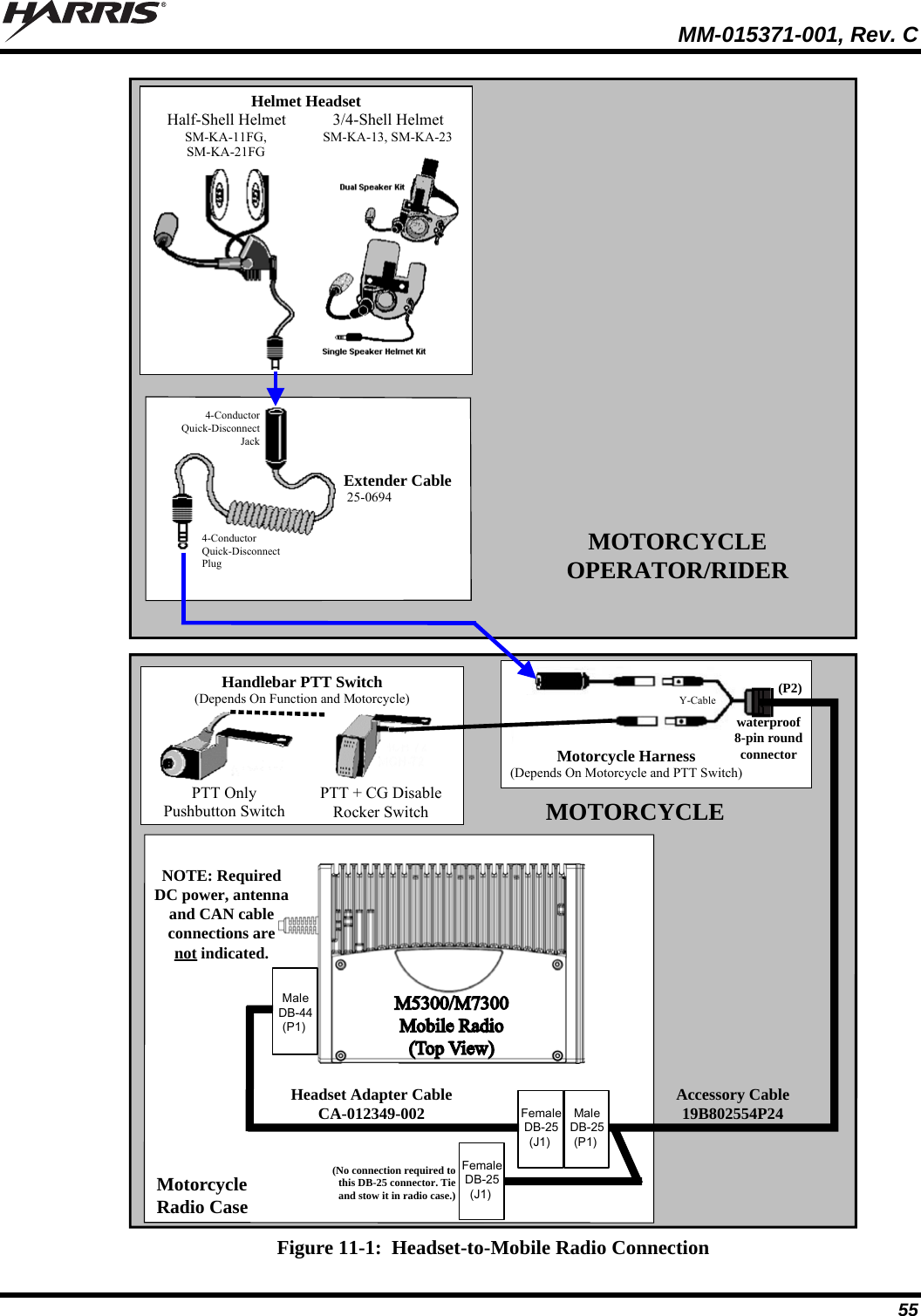
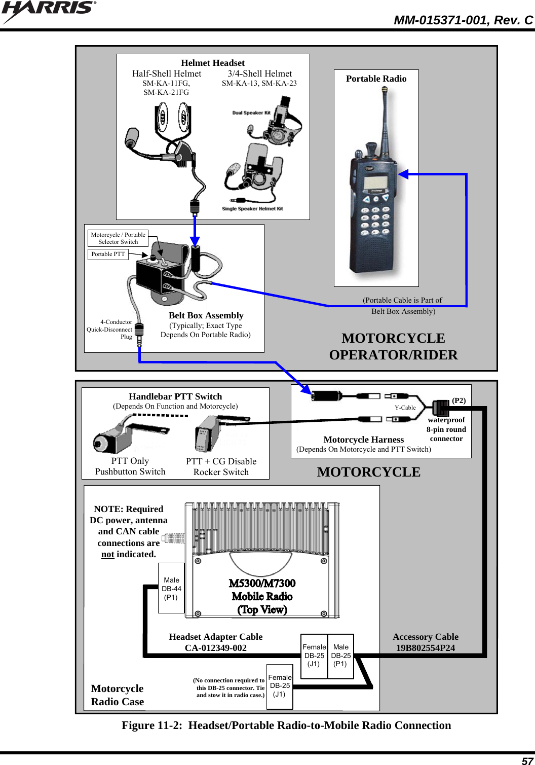
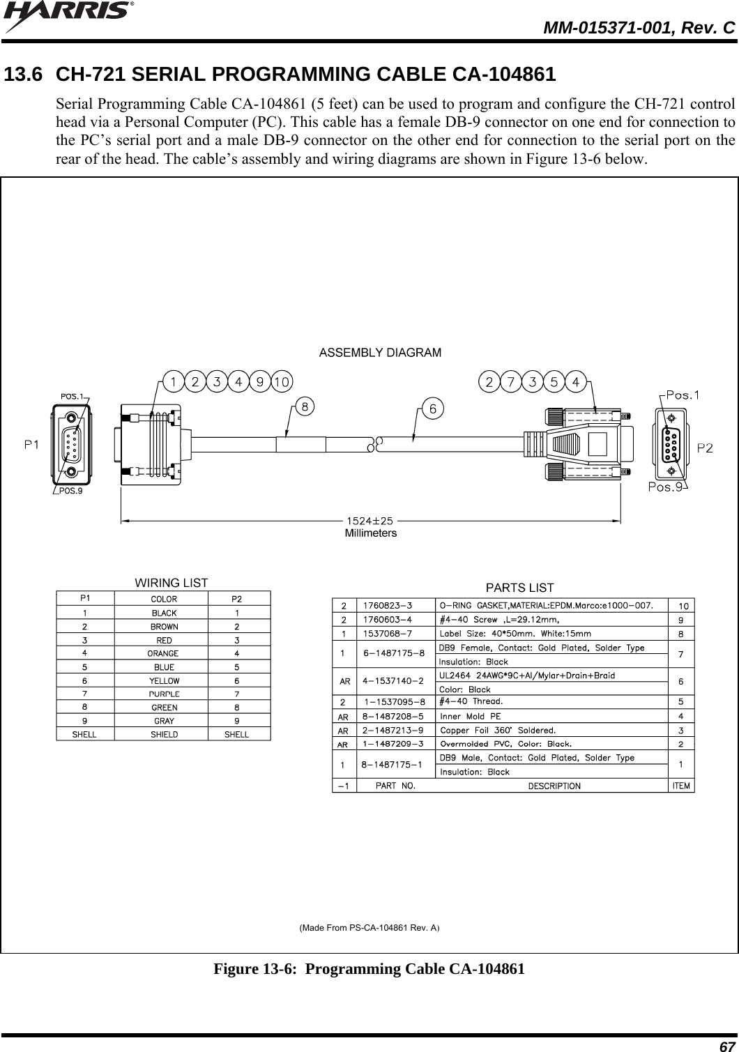
![MM-015371-001, Rev. C 13 Frequency Ranges of 700 & 800 MHz Radio (See footnote 2): Receive: 700 MHz Operation: 764 to 767 MHz, 769 to 775 MHz and 773 to 776 MHz (repeater and talk-around operations) [See footnote 3] 800 MHz Operation: 851 to 869 MHz (repeater and talk-around operations) Transmit: 700 MHz Talk-Around Operation: 764 to 767 MHz, 769 to 775 MHz and 773 to 776 MHz 700 MHz Repeater Operation: 794 to 797 MHz, 799 to 805 MHz and 803 to 806 MHz [See footnote 4] 800 MHz Talk-Around Operation: 851 to 869 MHz 800 MHz Repeater Operation: 806 to 824 MHz Transmit Output Power: 136 to 174 MHz RF Channels: 10 to 50 watts (see WARNING below) 800 MHz RF Channels: 5 to 35 watts (see WARNING below) Motorcycle applications of the M5300 and M7300 mobile radios are limited to 20 watts of maximum transmit RF output power. Refer to Section 1.2 (page 6), Section 5.4 (page 32), and Section 15 (page 69) for additional information. Channel Spacing: 12.5 kHz or 25 kHz or 30 kHz (mode dependent) Voice and Data Communications Modes: Half-Duplex Frequency Stability: ±1.5 ppm with AFC disabled; ±0.5 ppm with AFC Receiver Sensitivity: VHF P25 Mode (TIA-102 Method): -116 dBm minimum at 5% BER (static) VHF EDACS & Conventional Modes: -119 dBm minimum at 12 dB SINAD (25 kHz channels) 800 MHz OTP Mode: -111 dBm minimum at 1% BER (static) 800 MHz P25 Mode (TIA-102 Method): -116 dBm minimum at 5% BER (static) 800 MHz EDACS Mode: -118 dBm minimum at 12 dB SINAD Receiver Intermodulation Rejection: 77 dB typical Audio Frequency Response: 300 to 3000 Hz Audio Output Power from Control Head: 15 watts RMS minimum into 4-ohm external speaker; 1 watt into 4-ohm headset Audio Distortion from Control Head: < 5% at 5 watts RMS into 4-ohm external speaker Voice-Coding Method: OTP Mode: Advanced Multi-Band Excitation (AMBE™) EDACS, ProVoice and P25 Modes: Improved Multi-Band Excitation (IMBE™) P25 Phase 1 Mode: Advanced Multi-Band Excitation Plus (AMBE+™) OpenSky Data Rate: 19.2 kbps (9600 symbols per second) 2 700 MHz RF bands are listed for reference only. Motorcycle applications are limited to VHF and 800 MHz RF bands only. 3 764 to 767 MHz and 773 to 776 MHz per old FCC 700 MHz band plan. 769 to 775 MHz added August 30, 2007 by new FCC 700 MHz band plan. 4 764 to 767 MHz, 773 to 776 MHz, 794 to 797 MHz and 803 to 806 MHz per old FCC 700 MHz band plan. 769 to 775 MHz and 799 to 805 MHz added August 30, 2007 by new FCC 700 MHz band plan.](https://usermanual.wiki/HARRIS/TR-0055-E.Manual-2/User-Guide-1174093-Page-13.png)