HARRIS TR-0055-E M7300 VHF 50W Mobile Radio User Manual Manual 2
HARRIS CORPORATION M7300 VHF 50W Mobile Radio Manual 2
HARRIS >
Contents
- 1. Manual 1
- 2. Manual 2
- 3. Manual 3
- 4. manual 2
Manual 2

Installation and Product Safety Manual
MM-015371-001
Rev. C, Sep/09
M5300 and M7300
Mobile Radios
with CH-721 Control Heads
VHF and 800 MHz
Motorcycle Applications

MM-015371-001, Rev. C
2
MANUAL REVISION HISTORY
REV. DATE REASON FOR CHANGE
A Feb/09
Added references to 800 MHz M5300 radio, assembly and mounting figures, and
headset/portable radio connection section. Revised optional cables section. Revised
antenna test procedures.
B Jun/09
Revised specifications, microphone part numbers, ring terminal part number, and
optional cables.
C Sep/09
Added VHF M7300 radio, updated specifications, email addresses, and maximum
power and performance test procedures.
Harris Corporation, Public Safety and Professional Communications (PS&PC) Division continually evaluates its technical
publications for completeness, technical accuracy, and organization. You can assist in this process by submitting your
comments and suggestions to the following:
Harris Corporation fax your comments to: 1-434-455-6851
PS&PC Division or
Technical Publications e-mail us at: PSPC_TechPubs@harris.com
221 Jefferson Ridge Parkway
Lynchburg, VA 24501 ACKNOWLEDGEMENT
This device is made under license under one or more of the following US patents: 4,590,473; 4,636,791; 5,148,482;
5,185,796; 5,271,017; 5,377,229; 4,716,407; 4,972,460; 5,502,767; 5,146,497; 5,164,986; 5,185,795; 5,226,084; 5,247,579;
5,491,772; 5,517,511; 5,630,011; 5,649,050; 5,701,390; 5,715,365; 5,754,974; 5,826,222; 5,870,405; 6,161,089; and
6,199,037 B1. DVSI claims certain rights, including patent rights under aforementioned U.S. patents, and under other U.S.
and foreign patents and patents pending. Any use of this software or technology requires a separate written license from
DVSI. CREDITS
Harris, assuredcommunications, EDACS and OpenSky are registered trademarks of and ProVoice is a trademark of Harris
Corporation.
AMBE is a registered trademark and IMBE, AMBE+, and AMBE+2 are trademarks of Digital Voice Systems, Inc. Bird is a
registered trademark of Bird Electronic Corporation. Microsoft and Windows are registered trademarks of Microsoft
Corporation. SmartSiren is a registered trademark of Federal Signal Corporation. All other brand and product names are
trademarks, registered trademarks, or service marks of their respective holders.
NOTICE!
Information and descriptions contained herein are the property of Harris Corporation. Such information and descriptions may
not be copied or reproduced by any means, or disseminated or distributed without the express prior written permission of
Harris Corporation, PS&PC Division, 221 Jefferson Ridge Parkway, Lynchburg, VA 24501.
Repairs to this equipment should be made only by an authorized service technician or facility designated by the supplier. Any
repairs, alterations or substitutions of recommended parts made by the user to this equipment not approved by the
manufacturer could void the user's authority to operate the equipment in addition to the manufacturer's warranty.
This product conforms to the European Union WEEE Directive 2002/96/EC. Do not dispose of this
product in a public landfill. Take it to a recycling center at the end of its life.
This manual is published by Harris Corporation without any warranty. Improvements and changes to this manual
necessitated by typographical errors, inaccuracies of current information, or improvements to programs and/or equipment,
may be made by Harris Corporation at any time and without notice. Such changes will be incorporated into new editions o
f
this manual. No part of this manual may be reproduced or transmitted in any form or by any means, electronic or mechanical,
including photocopying and recording, for any purpose, without the express written permission of Harris Corporation.
Copyright © 2008, 2009, Harris Corporation

MM-015371-001, Rev. C
3
TABLE OF CONTENTS
Section Page
1 REGULATORY AND SAFETY INFORMATION....................................................................................6
1.1 SAFETY SYMBOL CONVENTIONS.................................................................................................6
1.2 RF ENERGY EXPOSURE AWARENESS AND CONTROL INFORMATION FOR FCC
OCCUPATIONAL USE REQUIREMENTS........................................................................................ 6
1.2.1 Federal Communications Commission Regulations............................................................... 7
1.3 COMPLIANCE WITH RF EXPOSURE STANDARDS...................................................................... 7
1.3.1 Mobile Antennas ....................................................................................................................8
1.3.2 Approved Accessories............................................................................................................8
1.3.3 Contact Information................................................................................................................8
1.4 OCCUPATIONAL SAFETY GUIDELINES AND SAFETY TRAINING INFORMATION .............9
1.5 COMMON HAZARDS ........................................................................................................................9
1.6 SAFE DRIVING RECOMMENDATIONS........................................................................................ 10
1.7 OPERATING RULES AND REGULATIONS ..................................................................................10
1.8 OPERATING TIPS.............................................................................................................................11
2 SPECIFICATIONS.....................................................................................................................................12
2.1 GENERAL..........................................................................................................................................12
2.2 TRANSCEIVER................................................................................................................................. 12
2.3 REGULATORY .................................................................................................................................14
3 INTRODUCTION.......................................................................................................................................15
3.1 GENERAL DESCRIPTION ...............................................................................................................15
3.1.1 VHF-Band M7300 Radio .....................................................................................................15
3.1.2 800 MHz-Band M5300 Radio .............................................................................................. 15
3.1.3 Dual-Band 700 and 800 MHz M7300 Radio........................................................................15
3.1.4 General Information .............................................................................................................16
3.2 RELATED PUBLICATIONS.............................................................................................................18
3.3 REPLACEMENT PARTS ..................................................................................................................19
3.4 TECHNICAL ASSISTANCE.............................................................................................................19
4 UNPACKING AND CHECKING THE EQUIPMENT...........................................................................20
4.1 GENERAL INFORMATION .............................................................................................................20
4.2 MOBILE RADIO, CONTROL HEAD AND MICROPHONE...........................................................20
4.3 INSTALLATION KITS...................................................................................................................... 22
4.4 ANTENNAS.......................................................................................................................................25
4.5 OPTIONS AND ACCESSORIES....................................................................................................... 25
4.6 MATERIALS NOT SUPPLIED .........................................................................................................27
5 PLANNING THE INSTALLATION.........................................................................................................28
5.1 GENERAL INFORMATION .............................................................................................................28
5.2 RECOMMENDED TOOLS ...............................................................................................................28
5.3 LOCATING COMPONENTS ............................................................................................................31
5.4 DC POWER CONSIDERATIONS..................................................................................................... 32
6 RADIO MECHANICAL INSTALLATION .............................................................................................33
6.1 INSTALLING THE ADAPTER BRACKET...................................................................................... 33
6.2 MOUNTING THE CASE AND CASE/ANTENNA BRACKET TO ADAPTER BRACKET...........33
6.3 INSTALLING THE RADIO IN THE CASE ......................................................................................35
6.3.1 Install the Radio’s Mounting Bracket................................................................................... 35
6.3.2 Install the Radio into Mounting Bracket...............................................................................35
7 ANTENNA INSTALLATION....................................................................................................................37
7.1 MOBILE ANTENNA INSTALLATION ...........................................................................................37
7.1.1 Install the Mobile Antenna ...................................................................................................37

MM-015371-001, Rev. C
4
TABLE OF CONTENTS
Section Page
7.1.2 Calculating the Antenna Cable Length .................................................................................37
7.1.3 Route Cable, Crimp-On TNC RF Connector and Connect It to the Radio ...........................38
8 CONTROL HEAD MECHANICAL INSTALLATION ..........................................................................40
8.1 GENERAL INFORMATION .............................................................................................................40
8.2 MOUNTING THE CONTROL HEAD...............................................................................................41
8.2.1 Selecting a Mounting Location.............................................................................................41
8.2.2 Control Head Adapter Bracket (Not Supplied).....................................................................43
8.2.3 Mounting the CH-721 Control Head ....................................................................................43
9 SPEAKER INSTALLATION.....................................................................................................................45
9.1.1 Selecting a Mounting Location.............................................................................................45
9.1.2 Mounting the Speaker...........................................................................................................45
10 CABLE CONNECTIONS...........................................................................................................................46
10.1 DC POWER CONNECTIONS ...........................................................................................................46
10.1.1 Overview of On/Off Power Wiring Configurations..............................................................46
10.1.2 Alternator Whine Reject Filter Installation...........................................................................46
10.1.3 DC Power Cable and Main Fuse Holder Installation............................................................47
10.1.4 Control Head Power Cable Installation ................................................................................49
10.2 CAN CABLE CONNECTIONS .........................................................................................................52
10.2.1 General Information..............................................................................................................52
10.2.2 Make CAN Link Terminations and Cable Connection.........................................................52
11 HEADSET/PORTABLE RADIO CONNECTIONS ................................................................................54
11.1 CONNECTING A HEADSET TO THE RADIO (WITHOUT BELT BOX) ......................................54
11.2 CONNECTING A HEADSET/PORTABLE RADIO TO THE MOBILE RADIO (WITH BELT
BOX)...................................................................................................................................................56
11.3 HEADSET OPERATION ...................................................................................................................58
12 MICROPHONE ATTACHMENT.............................................................................................................59
13 OPTIONAL CABLES.................................................................................................................................60
13.1 M5300/M7300 OPTION CABLE CA-012349-001 ............................................................................60
13.2 HEADSET ADAPTER CABLE CA-012349-002...............................................................................63
13.3 ACCESSORY CABLE 19B802554P24..............................................................................................64
13.4 SERIAL PROGRAMMING CABLES CA-013671-010 AND -020 ...................................................65
13.5 CH-721 OPTION CABLE CA-011854-001........................................................................................66
13.6 CH-721 SERIAL PROGRAMMING CABLE CA-104861.................................................................67
14 INITIAL POWER-UP TEST......................................................................................................................68
15 SETTING MAXIMUM TRANSMIT POWER LEVEL AND ANTENNA PERFORMANCE
TESTS ..........................................................................................................................................................69
15.1 CHANGING OPERATING MODE FOR TESTS...............................................................................69
15.1.1 Changing from OpenSky to Conventional............................................................................69
15.1.2 Changing from Conventional to OpenSky............................................................................70
15.2 REQUIRED TEST EQUIPMENT ......................................................................................................70
15.3 TRANSMIT POWER LEVEL ADJUSTMENTS ...............................................................................71
15.3.1 General Information..............................................................................................................71
15.3.2 Adjusting Maximum Transmit Output Power for EDACS/ProVoice, Conventional, and
P25 Modes ............................................................................................................................71
15.3.3 Adjusting Maximum Transmit Output Power for OpenSky Mode (Optional) .....................72
15.4 TRANSMITTING INTO A DUMMY LOAD.....................................................................................73
15.5 TRANSMITTING INTO THE MOBILE ANTENNA........................................................................75
15.6 TEST PERFORMANCE DATA FORM.............................................................................................77

MM-015371-001, Rev. C
5
TABLE OF CONTENTS
Section Page
16 COMPLETE THE INSTALLATION .......................................................................................................78
17 WARRANTY...............................................................................................................................................79
LIST OF FIGURES
Page
Figure 5-1: Typical Motorcycle Installation (Full View from Rear)...................................................................29
Figure 5-2: Typical Motorcycle Installation (Partial View of Radio Case and Brackets from Right Side) ........29
Figure 5-3: M5300/M7300 Mobile Radio inside Weather-Resistant Motorcycle Radio Case............................ 30
Figure 5-4: M5300/M7300 Mobile Radio — Front and Rear Views (Radio Removed from Case) ...................31
Figure 6-1: Assembling, Mounting and Installing the Radio Case and Brackets................................................ 34
Figure 6-2: Alternate Mounting for Adapter Bracket..........................................................................................35
Figure 6-3: Installing the Radio’s Mounting Bracket and Filter into the Motorcycle Radio Case ...................... 36
Figure 7-1: Crimping Instructions for TNC RF Connector .................................................................................38
Figure 8-1: CH-721 Scan Model Control Head Front Panel ...............................................................................40
Figure 8-2: CH-721 System Model Control Head Front Panel ...........................................................................40
Figure 8-3: CH-721 Rear Panel (both control head models)............................................................................... 41
Figure 8-4: Typical CH-721 Control Head Installation on a Motorcycle (Using the Standard U-Shaped
Mounting Bracket)....................................................................................................................... 42
Figure 8-5: Optional Control Head Mounting Pedestal (Part Number MACDOS0012).....................................42
Figure 10-1: CAN Terminators and Control Head-to-Radio CAN Cable Connection........................................ 53
Figure 11-1: Headset-to-Mobile Radio Connection ............................................................................................55
Figure 11-2: Headset/Portable Radio-to-Mobile Radio Connection ...................................................................57
Figure 12-1: Attaching the Microphone to the CH-721Control Head................................................................. 59
Figure 13-1: M5300/M7300 Option Cable CA-012349-001...............................................................................60
Figure 13-2: Headset Adapter Cable CA-012349-002 ........................................................................................63
Figure 13-3: Accessory Cable 19B802554P24 ...................................................................................................64
Figure 13-4: Programming Cables CA-013671-010 and CA-013671-020.......................................................... 65
Figure 13-5: CH-721 Option Cable CA-011854-001..........................................................................................66
Figure 13-6: Programming Cable CA-104861 ....................................................................................................67
Figure 15-1: Setting Maximum RF Output Power Level via RPM’s System Setup Dialog Box........................72
Figure 15-2: Wattmeter Connections for Antenna System Tests ........................................................................74
LIST OF TABLES
Page
Table 1-1: Recommended Minimum Safe Lateral Distance from Transmitting Antenna...................................... 8
Table 4-1: Motorcycle Installation Kits for M5300/M7300 Mobile Radios with CH-721 Control Heads.......... 22
Table 4-2: Contents of M5300/M7300 Motorcycle Installation Kits ..................................................................22
Table 4-3: Antennas for Motorcycle Applications of the M5300 and M7300 Mobile Radios............................25
Table 4-4: Additional Options and Accessories for M5300 and M7300 Mobile Radios ....................................25
Table 4-5: Options and Accessories for CH-721 Control Heads.........................................................................26
Table 4-6: Headset-Related Options for Use with M5300 and M7300 Mobile Radios.......................................27
Table 13-1: M5300/M7300 Option Cable CA-012349-001 Interconnections.....................................................61
Table 15-1: Required Test Equipment ................................................................................................................70
(Continued)
MM-015371-001, Rev. C
6
1 REGULATORY AND SAFETY INFORMATION
1.1 SAFETY SYMBOL CONVENTIONS
The following conventions are used in this manual to alert the user to general safety precautions that must
be observed during all phases of operation, installation, service, and repair of this product. Failure to
comply with these precautions or with specific warnings elsewhere violates safety standards of design,
manufacture, and intended use of the product. Harris Corporation assumes no liability for the customer's
failure to comply with these standards.
The WARNING symbol calls attention to a procedure, practice, or the like, which,
if not correctly performed or adhered to, could result in personal injury. Do not
proceed beyond a WARNING symbol until the conditions identified are fully
understood or met.
CAUTION
The CAUTION symbol calls attention to an operating procedure, practice, or the like,
which, if not performed correctly or adhered to, could result in damage to the
equipment or severely degrade equipment performance.
The NOTE symbol calls attention to supplemental information, which may improve
system performance or clarify a process or procedure.
1.2 RF ENERGY EXPOSURE AWARENESS AND CONTROL
INFORMATION FOR FCC OCCUPATIONAL USE REQUIREMENTS
Before using the two-way mobile radio, read this important RF energy awareness and control
information and operational instructions to ensure compliance with RF exposure guidelines.
This radio is intended for use in occupational/controlled conditions, where users
have full knowledge of their exposure and can exercise control over their
exposure to remain below RF exposure limits. This radio is NOT authorized for
general population, consumer, or any other use.
CAUTION
Changes or modifications not expressly approved by Harris could void the user's
authority to operate the equipment.
This two-way radio uses electromagnetic energy in the radio frequency (RF) spectrum to provide
communications between two or more users over a distance. It uses RF energy or radio waves to send and
receive calls. RF energy is one form of electromagnetic energy. Other forms include, but are not limited
to, electric power, sunlight, and x-rays. RF energy, however, should not be confused with these other
forms of electromagnetic energy, which, when used improperly, can cause biological damage. Very high
levels of x-rays, for example, can damage tissues and genetic material.
Experts in science, engineering, medicine, health, and industry work with organizations to develop
standards for exposure to RF energy. These standards provide recommended levels of RF exposure for
MM-015371-001, Rev. C
7
both workers and the general public. These recommended RF exposure levels include substantial margins
of protection. All two-way radios marketed in North America are designed, manufactured, and tested to
ensure they meet government-established RF exposure levels. In addition, manufacturers also recommend
specific operating instructions to users of two-way radios. These instructions are important because they
inform users about RF energy exposure and provide simple procedures on how to control it. Refer to the
following websites for more information on what RF energy exposure is and how to control exposure to
assure compliance with established RF exposure limits:
http://www.fcc.gov/oet/rfsafety/rf-faqs.html
http://www.osha.gov./SLTC/radiofrequencyradiation/index.html
1.2.1 Federal Communications Commission Regulations
Before marketing in the United States, the M5300 and M7300 two-way mobile radios were tested to
ensure compliance with FCC RF energy exposure limits for two-way mobile radios. When two-way
radios are used as a consequence of employment, the FCC requires users to be fully aware of and able to
control their exposure to meet occupational requirements. Exposure awareness can be facilitated by the
use of a label directing users to specific user awareness information. Each radio has an RF exposure
product label. Also, this Installation and Product Safety Manual and the applicable Operator’s Manual
include information and operating instructions required to control RF exposure and to satisfy compliance
requirements.
1.3 COMPLIANCE WITH RF EXPOSURE STANDARDS
The M5300 and M7300 two-way mobile radios are designed and tested to comply with a number of
national and international standards and guidelines regarding human exposure to RF electromagnetic
energy. The radios comply with the IEEE and ICNIRP exposure limits for occupational/controlled RF
exposure environment at duty-cycle times of up to 50% (50% transmit, 50% receive), and they are
authorized by the FCC for occupational use. In terms of measuring RF energy for compliance with the
FCC exposure guidelines, each radio’s antenna radiates measurable RF energy only while it is
transmitting (talking), not while it is receiving (listening), or in a standby mode.
The M5300 and M7300 two-way mobile radios comply with the following RF energy exposure standards
and guidelines:
United States Federal Communications Commission (FCC), Code of Federal Regulations; 47 CFR
§ 2 sub-part J.
American National Standards Institute (ANSI)/Institute of Electrical and Electronic Engineers (IEEE)
C95.1-2005.
Institute of Electrical and Electronic Engineers (IEEE) C95.1-2005.
IC Standard RSS-102, Issue 2, 2005: “Spectrum Management and Telecommunications Radio
Standards Specification. Radiofrequency Exposure Compliance of Radiocommunication Apparatus
(All Frequency Bands).”
CAUTION
Table 1-1 lists the recommended minimum safe lateral distances for a controlled
environment and for unaware bystanders in an uncontrolled environment, from
transmitting antennas (i.e., monopoles over a ground plane, or dipoles) at rated radio
power for a mobile radio installed in a vehicle. Transmit only when unaware
bystanders are at the uncontrolled recommended minimum safe lateral distance away
from the transmitting antenna.
MM-015371-001, Rev. C
8
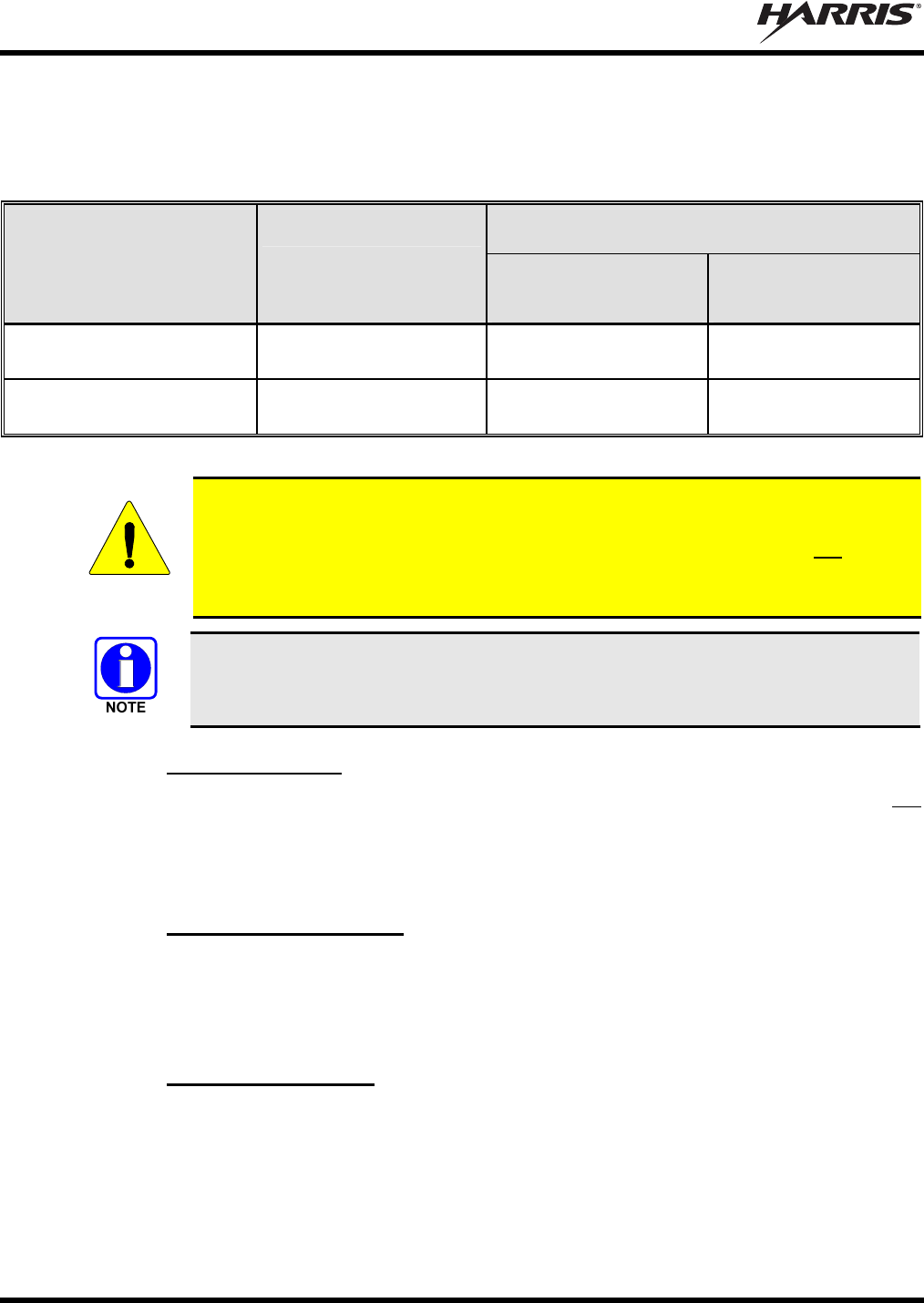
Based on the highest radiated RF power and the highest gain antenna used with the radio in a motorcycle
installation, the distances listed in Table 1-1 are considered as safe distances for controlled and
uncontrolled environments with the radio transmitting at a maximum 50% duty cycle.
Table 1-1: Recommended Minimum Safe Lateral Distance from Transmitting Antenna
RECOMMENDED MINIMUM LATERAL HUMAN BODY
DISTANCE FROM TRANSMITTING ANTENNA
ANTENNA
PART NUMBER
(Catalog Number) ANTENNA DESCRIPTION CONTROLLED
ENVIRONMENT
(Centimeters)
UNCONTROLLED
ENVIRONMENT
(Centimeters)
LE-OM150K.125/TNC 136 to 174 MHz;
2.5 dBd Gain 53 118
LE-OM806HDBKTNCDS 800 MHz;
3.5 dBd Gain 28 72
CAUTION
A radio intended for a motorcycle installation must be configured to not exceed a
transmit output power of 20 watts. Refer to Section 15.3 on page 71 for additional
information. A radio intended for a non-motorcycle installation should not be used
in a motorcycle installation unless it is reprogrammed per the procedures
presented in Section 15.3.
The dual-band M7300 mobile radio can operate on both 700 and 800 MHz bands.
However, as of the publication of this manual, motorcycle applications are limited
to the 800 MHz band only.
1.3.1 Mobile Antennas
The antenna for the mobile radio must be installed in accordance with Section 7 in this manual and
instructions included with the antenna.
Use only the approved/supplied antenna(s) or an approved replacement antenna. Unauthorized antennas,
modifications, or attachments can cause the FCC RF exposure limits to be exceeded.
1.3.2 Approved Accessories
The radio has been tested and meets FCC RF guidelines when used with accessories supplied or
designated for use with it. Use of other accessories may not ensure compliance with the FCC’s RF
exposure guidelines, and may violate FCC regulations. For a list of approved accessories refer to Section
4 in this manual (begins on page 20) and/or Harris’ Products and Services Catalog.
1.3.3 Contact Information
For additional information on RF exposure and other information, contact Harris using one of the contact
links listed in Section 3.4 on page 19.

MM-015371-001, Rev. C
9
1.4 OCCUPATIONAL SAFETY GUIDELINES AND SAFETY TRAINING
INFORMATION
To ensure bodily exposure to RF electromagnetic energy is within the FCC allowable limits for
occupational use. Always adhere to the following basic guidelines:
The push-to-talk button should only be depressed when intending to send a voice message.
The radio should only be used for necessary work-related communications.
The radio should only be used by authorized and trained personnel. It should never be operated by
children.
Do not attempt any unauthorized modification to the radio. Changes or modifications to the radio may
cause harmful interference and/or cause it to exceed FCC RF exposure limits. Only qualified
personnel should service the radio.
Always use Harris-authorized accessories (antennas, control heads, speakers/mics, etc.). Use of
unauthorized accessories can cause the FCC RF exposure compliance requirements to be exceeded.
The information listed above provides the user with information needed to make him or her aware of a RF
exposure, and what to do to assure that this radio operates within the FCC exposure limits of this radio.
1.5 COMMON HAZARDS
The operator of any mobile radio should be aware of certain hazards common to
the operation of vehicular radio transmissions. Possible hazards include but are
not limited to:
Explosive Atmospheres — Just as it is dangerous to fuel a vehicle while its motor running, be sure
to turn the radio OFF while fueling the vehicle. If the radio is mounted in the trunk of the vehicle,
DO NOT carry containers of fuel in the trunk.
Areas with potentially explosive atmosphere are often, but not always, clearly marked. Turn the radio
OFF when in any area with a potentially explosive atmosphere. It is rare, but not impossible that the
radio or its accessories could generate sparks.
Interference To Vehicular Electronic Systems — Electronic fuel injection systems, electronic anti-
skid braking systems, and electronic cruise control systems, etc., are typical types of electronic
devices that can malfunction due to the lack of protection from radio frequency (RF) energy present
when transmitting. If the vehicle contains such equipment, consult the dealer for the make of vehicle
and enlist his aid in determining if such electronic circuits perform normally when the radio is
transmitting.
Electric Blasting Caps — To prevent accidental detonation of electric blasting caps, DO NOT use
two-way radios within 1000 feet (305 meters) of blasting operations. Always obey the “Turn Off
Two-Way Radios” (or equivalent) signs posted where electric blasting caps are being used (OSHA
Standard: 1926.900).
Radio Frequency Energy — To prevent burns or related physical injury from radio frequency
energy, do not operate the radio’s transmitter when anyone near the motorcycle is within the
minimum safe distance from the antenna as specified in Table 1-1. Refer to Section 1.2 for additional
information.
Vehicles Powered By Liquefied Petroleum (LP) Gas — Radio installation in vehicles powered by
liquefied petroleum gas, where the LP gas container is located in the trunk or other sealed-off space

MM-015371-001, Rev. C
10
within the interior of the vehicle, must conform to the National Fire Protection Association standard
NFPA 58. This requires:
The space containing the radio equipment must be isolated by a seal from the space containing
the LP gas container and its fittings.
Outside filling connections must be used for the LP gas container.
The LP gas container space shall be vented to the outside of the vehicle.
1.6 SAFE DRIVING RECOMMENDATIONS
The American Automobile Association (AAA) advocates the following key safe driving recommenda-
tions:
Read the literature on the safe operation of the radio.
Use both hands to steer and keep the microphone in its hanger whenever the vehicle is in motion.
Place calls only when the vehicle is stopped.
When talking from a moving vehicle is unavoidable, drive in the slower lane. Keep conversations
brief.
If a conversation requires taking notes or complex thought, stop the vehicle in a safe place and
continue the call.
Whenever using a mobile radio, exercise caution.
1.7 OPERATING RULES AND REGULATIONS
Two-way radio systems must be operated in accordance with the rules and regulations of the local,
regional, or national government.
In the United States, the mobile radio must be operated in accordance with the rules and regulations of the
Federal Communications Commission (FCC). Operators of two-way radio equipment, must be thoroughly
familiar with the rules that apply to the particular type of radio operation. Following these rules helps
eliminate confusion, assures the most efficient use of the existing radio channels, and results in a
smoothly functioning radio network.
When using a two-way radio, remember these rules:
It is a violation of FCC rules to interrupt any distress or emergency message. The radio operates in
much the same way as a telephone “party line.” Therefore, always listen to make sure the channel is
clear before transmitting. Emergency calls have priority over all other messages. If someone is
sending an emergency message – such as reporting a fire or asking for help in an accident, do not
transmit unless assistance can be offered.
The use of profane or obscene language is prohibited by Federal law.
It is against the law to send false call letters or false distress or emergency messages. The FCC
requires keeping conversations brief and confine them to business. To save time, use coded messages
whenever possible.
Using the radio to send personal messages (except in an emergency) is a violation of FCC rules. Send
only essential messages.
It is against Federal law to repeat or otherwise make known anything overheard on the radio.
Conversations between others sharing the channel must be regarded as confidential.
MM-015371-001, Rev. C
11
The FCC requires self-identification at certain specific times by means of call letters. Refer to the
rules that apply to the particular type of operation for the proper procedure.
No changes or adjustments shall be made to the equipment except by an authorized or certified
electronics technician.
CAUTION
Under U.S. law, operation of an unlicensed radio transmitter within the jurisdiction of
the United States may be punishable by a fine of up to $10,000, imprisonment for up to
two (2) years, or both.
1.8 OPERATING TIPS
The following conditions tend to reduce the effective range of two-way radios and should be avoided
whenever possible:
Operating the radio in areas of low terrain, or while under power lines or bridges.
Obstructions such as mountains and buildings.
In areas where transmission or reception is poor, communication improvement may
sometimes be obtained by moving a few yards in another direction, or moving to a
higher elevation.

MM-015371-001, Rev. C
12
2 SPECIFICATIONS1
2.1 GENERAL
Dimensions, Remote-Mount Mobile Radio: 2.0 x 6.9 x 9.2 inches (5.1 x 17.5 x 23.4 centimeters)
(Height x Width x Depth) (Does not include space required for mounting bracket
and cables at rear of radio)
Dimensions, Control Head: 2.4 x 6.9 x 3.9 inches (6 x 17.5 x 10 centimeters)
(Height x Width x Depth) (Does not include bracket and mounting screws)
Dimensions, Motorcycle Radio Case: 4.6 x 10.1 x 17.9 inches (11.7 x 25.7 x 45.5 centimeters)
(Height x Width x Depth) (Does not include space required for brackets, cables,
antenna, and key access)
Weight, Remote-Mount Mobile Radio: 5.25 pounds (3.69 kilograms), less bracket
Weight, Control Head: 1.25 pounds (0.57 kilograms), less bracket
Operating Ambient Temperature Range: -22 to +140° Fahrenheit (-30 to +60° Celsius)
Storage Temperature Range: -40 to +185° Fahrenheit (-40 to +85° Celsius)
Altitude: 15,000 feet (4572 meters) maximum
DC Supply Voltage Operating Range: +13.6 Vdc ±10% (Normal range per TIA-603)
DC Supply Current Requirements:
Receive (includes control head):
With Speaker Muted: 1.1 amps maximum
With 0.5-Watt Speaker Output Power: 1.5 amps maximum
With 10-Watt Speaker Output Power: 3.5 amps maximum
With 15-Watt Speaker Output Power: 4.0 amps maximum
Transmit (includes control head):
VHF Radio at 15 Watts: 7 amps maximum, 5 amps typical
VHF Radio at 20 Watts: 8 amps maximum, 6 amps typical
700 & 800 MHz Radio at 12 Watts: 8 amps maximum, 6 amps typical
700 & 800 MHz Radio at 20 Watts: 10 amps maximum, 8.8 amps typical
Quiescent/Off Current:
Mobile Radio: 100 microamps maximum
Control Head: 100 microamps maximum
2.2 TRANSCEIVER
Frequency Ranges of VHF Radio:
Receive: 136 to 174 MHz
Transmit: 136 to 174 MHz
1 These specifications are primarily intended for the use of the installation technician. See the appropriate Specifications
Sheet for the complete specifications.
MM-015371-001, Rev. C
13
Frequency Ranges of 700 & 800 MHz Radio (See footnote 2):
Receive:
700 MHz Operation: 764 to 767 MHz, 769 to 775 MHz and 773 to 776 MHz
(repeater and talk-around operations) [See footnote 3]
800 MHz Operation: 851 to 869 MHz (repeater and talk-around operations)
Transmit:
700 MHz Talk-Around Operation: 764 to 767 MHz, 769 to 775 MHz and 773 to 776 MHz
700 MHz Repeater Operation: 794 to 797 MHz, 799 to 805 MHz and 803 to 806 MHz
[See footnote 4]
800 MHz Talk-Around Operation: 851 to 869 MHz
800 MHz Repeater Operation: 806 to 824 MHz
Transmit Output Power:
136 to 174 MHz RF Channels: 10 to 50 watts (see WARNING below)
800 MHz RF Channels: 5 to 35 watts (see WARNING below)
Motorcycle applications of the M5300 and M7300 mobile radios are limited to 20
watts of maximum transmit RF output power. Refer to Section 1.2 (page 6),
Section 5.4 (page 32), and Section 15 (page 69) for additional information.
Channel Spacing: 12.5 kHz or 25 kHz or 30 kHz (mode dependent)
Voice and Data Communications Modes: Half-Duplex
Frequency Stability: ±1.5 ppm with AFC disabled; ±0.5 ppm with AFC
Receiver Sensitivity:
VHF P25 Mode (TIA-102 Method): -116 dBm minimum at 5% BER (static)
VHF EDACS & Conventional Modes: -119 dBm minimum at 12 dB SINAD (25 kHz channels)
800 MHz OTP Mode: -111 dBm minimum at 1% BER (static)
800 MHz P25 Mode (TIA-102 Method): -116 dBm minimum at 5% BER (static)
800 MHz EDACS Mode: -118 dBm minimum at 12 dB SINAD
Receiver Intermodulation Rejection: 77 dB typical
Audio Frequency Response: 300 to 3000 Hz
Audio Output Power from Control Head: 15 watts RMS minimum into 4-ohm external speaker;
1 watt into 4-ohm headset
Audio Distortion from Control Head: < 5% at 5 watts RMS into 4-ohm external speaker
Voice-Coding Method:
OTP Mode: Advanced Multi-Band Excitation (AMBE™)
EDACS, ProVoice and P25 Modes: Improved Multi-Band Excitation (IMBE™)
P25 Phase 1 Mode: Advanced Multi-Band Excitation Plus (AMBE+™)
OpenSky Data Rate: 19.2 kbps (9600 symbols per second)
2 700 MHz RF bands are listed for reference only. Motorcycle applications are limited to VHF and 800 MHz RF bands only.
3 764 to 767 MHz and 773 to 776 MHz per old FCC 700 MHz band plan. 769 to 775 MHz added August 30, 2007 by new
FCC 700 MHz band plan.
4 764 to 767 MHz, 773 to 776 MHz, 794 to 797 MHz and 803 to 806 MHz per old FCC 700 MHz band plan. 769 to
775 MHz and 799 to 805 MHz added August 30, 2007 by new FCC 700 MHz band plan.

MM-015371-001, Rev. C
14
OpenSky Compressed Voice
Relative Data Rate: 2400 bps
2.3 REGULATORY
FCC Type Acceptance:
VHF Radio: OWDTR-0055-E
700 & 800 MHz Radio OWDTR-0051-E
Applicable FCC Rules: Part 15 and Part 90
Industry Canada Certification:
VHF Radio: 3636B-0055
700 & 800 MHz Radio 3636B-0051
Applicable Industry Canada Rules: RSS-119

MM-015371-001, Rev. C
15
3 INTRODUCTION
This installation and product safety manual covers motorcycle applications of the M5300 and M7300
mobile radios. Instructions are included for radio installation and testing, along with applicable safety
information.
3.1 GENERAL DESCRIPTION
The M5300 and M7300 mobile radios are high-performance digital mobile radios. Three (3) different
radios are available for motorcycle applications:
3.1.1 VHF-Band M7300 Radio
The VHF-band M7300 mobile radio can operate in the 136 to 174 MHz RF band with the following radio
systems/standards:
APCO Project 25 Phase I compliant Common Air Interface (P25 CAI) trunked radio networks;
Talk-around communications in accordance with the APCO Project 25 Phase I standard; and,
Conventional FM repeater-based and FM talk-around voice communications in the VHF-band in
accordance with the TIA/EIA-603 conventional land-mobile radio standard.
The VHF-band M7300 radio has a high-power transmit rating of 50 watts. However, motorcycle
applications are limited to 20 watts.
3.1.2 800 MHz-Band M5300 Radio
The 800 MHz M5300 mobile radio can operate with the following radio systems/standards:
800 MHz Enhanced Digital Access Communications System (EDACS®) trunked radio networks;
800 MHz ProVoice™ trunked radio networks;
800 MHz APCO Project 25 Phase I compliant Common Air Interface (P25 CAI) trunked radio
networks; and,
Conventional FM repeater-based and FM talk-around voice communications in the 800 MHz band in
accordance with the TIA/EIA-603 conventional land-mobile radio standard.
800 MHz operating bands of the 800 MHz M5300 mobile radio include 806 to 824 MHz repeater input
band (mobile transmit) and the 851 to 869 MHz band used for repeater output and talk-around
communications. In high-power transmit mode on an 800 MHz RF channel, the radio’s rated transmit
output power is 35 watts. However, motorcycle applications are limited to 20 watts.
3.1.3 Dual-Band 700 and 800 MHz M7300 Radio
The dual-band 700 and 800 MHz M7300 mobile radio can operate with the following radio systems/-
standards:
700 MHz and 800 MHz OpenSky® trunked radio networks using the OpenSky Trunking Protocol
(OTP);
800 MHz Enhanced Digital Access Communications System (EDACS®) trunked radio networks;
800 MHz ProVoice™ trunked radio networks;
800 MHz APCO Project 25 Phase I compliant Common Air Interface (P25 CAI) trunked radio
networks;
700 MHz talk-around communications in accordance with the APCO Project 25 Phase I standard;
and,
MM-015371-001, Rev. C
16
Conventional FM repeater-based and FM talk-around voice communications in 700 and 800 MHz
bands in accordance with the TIA/EIA-603 conventional land-mobile radio standard.
700 MHz operating bands of the dual-band M7300 mobile radio include the repeater output bands
(mobile receive) of 764 to 767 MHz, 769 to 775 MHz and 773 to 776 MHz, and the repeater input bands
(mobile transmit) of 794 to 797 MHz, 799 to 805 MHz and 803 to 806 MHz. The radio also provides
talk-around operation in the 764 to 767 MHz, 769 to 775 MHz and 773 to 776 MHz bands. In high-power
transmit mode on a 700 MHz RF channel, the radio’s rated transmit output power is 19 watts.
800 MHz operating bands of the dual-band M7300 mobile radio include 806 to 824 MHz repeater input
band (mobile transmit) and the 851 to 869 MHz band used for repeater output and talk-around
communications. In high-power transmit mode on an 800 MHz RF channel, the radio’s rated transmit
output power is 35 watts. However, motorcycle applications are limited to 20 watts.
The dual-band M7300 mobile radio can operate on both 700 and 800 MHz bands.
However, as of the publication of this manual, motorcycle applications are limited
to the 800 MHz band only.
3.1.4 General Information
In motorcycle applications, the radio is mounted in a weather-resistant case. This case is secured to the
motorcycle’s frame behind the seat of the motorcycle. The radio’s control head is located near the
motorcycle operator position. The radio is shown in the case in Figure 5-3 on page 30.
Control heads used with the M5300 and M7300 mobile radios include the CH-721 Scan and the CH-721
System model control heads. See Figure 8-1 through Figure 8-3 (pages 40 through 41). Both heads
feature a large 3-line graphical vacuum-florescent display, front panel controls and buttons for user
control of the mobile radio, an internal high-power audio amplifier to drive an externally-connected
speaker, and a front panel microphone connector. The CH-721 System control head also has a 12-button
numeric keypad that provides Dual-Tone Multi-Frequency (DTMF) functionality and easier operator
system/group selection control at the control head’s front panel.
The radio is remotely controlled by a control head via a Controller Area Network (CAN) link between the
radio and control head. A 3-wire CAN cable provides the CAN link interconnection between the two
units. The CAN link carries digitized microphone and speaker audio, controlling data such as button
presses and radio messages, and user data such as that for a mobile data terminal connected to the serial
port of the radio or control head. For proper operation, the CAN link must be terminated appropriately on
each end.
As shown in Figure 8-3 on page 41, the CH-721 Scan and System model control heads have several
connectors located on the head’s rear panel. These connectors include a DC power connector, two (2)
CAN port connectors used for CAN link interconnections, an external speaker connector, a 9-pin serial
port connector for connecting optional equipment such as a mobile data terminal, and a 25-pin accessory
connector. Both CH-721 models can interface to an optional Federal Signal Electronic siren/light control
system for broadcasting via a public address (PA) speaker.
The radio must be powered by an external +13.6-volt (nominal) DC power source. In motorcycle
applications, the motorcycle’s electrical system is utilized as the source of DC power. The control head
connected to the radio is also powered by the same DC power source, but separately fused. When the
control head is powered-up by the operator, it “wakes up” the radio by transmitting data to the radio via
the CAN link.
The radio provides half-duplex voice and data communications. Voice communications are accomplished
via a “push-to-talk” (PTT) type microphone and a speaker connected to the control head.

MM-015371-001, Rev. C
17
For data communications, the radio has an industry-standard 9-pin serial interface port for connecting
optional data-type equipment, such as a Mobile Data Terminal (MDT), a laptop PC, an external display,
or a key-entry device. This port works seamlessly with equipment from popular manufacturers and off-
the-shelf applications. OpenSky employs User Datagram Protocol over Internet Protocol (UDP/IP) data
packet transfers, providing “plug and play” connectivity for data-type devices.
The radio and control head exceed tough environmental specifications included within military standard
MIL-STD-810F, the radio industry standard TIA/EIA-603, and the radio standard established by the U.S.
Forest Service.
A radio operating on an OpenSky radio network uses Time-Division Multiple-Access (TDMA) digital
modulation technology on the radio frequency link. TDMA allows multiple radio users to share a single
RF channel. In addition, a single RF channel can support simultaneous digital voice and data
communications.
OpenSky employs Advanced Multi-Band Excitation (AMBE) speech and data compression technology
developed by Digital Voice Systems, Inc. When operating on an OpenSky radio network, AMBE gives
an M5300/M7300 radio the ability to provide exceptional voice quality via the limited bandwidth of the
radio frequency path, even when the received RF signal is weak (i.e., even in “fringe” areas). AMBE is
performed by a Digital Signal Processor (DSP) integrated circuit within the radio programmed to perform
an AMBE compression algorithm during mobile transmissions, and an AMBE expansion algorithm
during mobile reception.
Speech compression electronic circuitry—be it AMBE or another type such as IMBE—is sometimes
referred to as “vocoding” circuitry for voice coding, or simply a “vocoder” circuit.
The M7300 mobile radio also supports radio operation on APCO Project 25 Phase I compliant Common
Air Interface (P25 CAI) trunked radio networks, and operation in a talk-around mode in accordance with
the APCO Project 25 Phase I standard. P25 radio systems utilize Improved Multi-Band Excitation
(IMBE) speech/data compression technology, also developed by Digital Voice Systems, Inc.
Like AMBE technology, IMBE technology gives the radio the ability to deliver exceptional voice quality,
even in areas where the received RF signal strength is weak. IMBE replicates human speech better than
other voice compression technologies, resulting in better voice quality and better speaker recognition. The
Telecommunications Industry Association (TIA) funded an independent study to evaluate compression
technologies. The findings showed that when compared with other industry-recognized compression
technologies, IMBE provided the highest voice quality. In the study, radio users were asked to listen to
coded speech produced by four different compression technologies (i.e., vocoder circuits) operating under
a variety of conditions. The users rated the speech on a scale of one to five, with five being the best
quality. Under each operating condition, IMBE was rated the best.
The M5300 and M7300 mobile radios can also operate using Harris’ digital voice technology called
ProVoice. Like P25 radio systems, ProVoice also employs the Improved Multi-Band Excitation
(IMBE™) speech/data compression technology.
EDACS and ProVoice trunked radio networks employ analog FM and 2-level Gaussian Frequency-Shift
Keying (GFSK) modulation techniques on the RF channels. Data is transmitted on an RF channel at a
9600 baud rate.
For over-the-air secure radio communications, the M5300 and M7300 mobile radios may be equipped
with 64-bit DES (Data Encryption Standard) encryption or with 128/256-bit AES (Advanced Encryption
Standard) encryption. With encryption, voice and/or user data signals transmitted and received by the
radio on an RF channel are digitally encrypted (“scrambled”) to virtually eliminate unauthorized
monitoring via the RF channel.
MM-015371-001, Rev. C
18
Encryption requires an encryption-capable radio.
Cryptographic keys are stored in the radio by the radio system administration personnel. Keys can be sent
to an M7300 radio via an RF channel if it is equipped with the Over-the-Air Rekeying (OTAR) option. As
of the publication of this manual, the OTAR option is not available for the M5300 radio.
CAUTION
Harris recommends the buyer use only a Harris-authorized representative to
install and service this product. The warranties provided to the buyer under the terms
of sale shall be null and void if this product is installed or serviced improperly, and
Harris shall have no further obligation to the buyer for any damage caused to the
product or to any person or personal property.
3.2 RELATED PUBLICATIONS
The following publications contain additional information about the M5300 and M7300 mobile radios:
M5300 Quick Guide for EDACS/ProVoice and Conventional Modes: MM-013232-001
M5300 Quick Guide for OpenSky: MM-012997-001
M5300 Operator’s Manual for EDACS/ProVoice, OpenSky and
Conventional Modes: MM-012125-001
M7300 Quick Guide for EDACS/ProVoice, P25 and Conventional Modes: MM-014369-001
M7300 Quick Guide for OpenSky: MM-014368-001
M7300 Operator’s Manual for EDACS/ProVoice, OpenSky, P25 and
Conventional Modes: MM-014716-001
M7300 Maintenance Manual, VHF: MM-017065-001
M5300 and M7300 Maintenance Manual, 700 and 800 MHz: MM-014718-001
Quick guides are included with each radio equipment package when it ships from the factory. Operator
manuals, installation manuals, maintenance manuals, and quick guides are available at
www.rfcomm.harris.com/publicsafety via a Wireless Systems’ Wireless Information Center login and
Tech Link.

MM-015371-001, Rev. C
19
3.3 REPLACEMENT PARTS
Replacement parts can be ordered through the Customer Resource Center. To order replacement parts
through the Customer Resource Center, call, fax or e-mail our ordering system:
United States and Canada:
Phone Number: 1-800-368-3277 (toll free)
Fax Number: 1-800-833-7592 (toll free)
E-mail: PSPC_tac@harris.com
International:
Phone Number: 1-434-455-6403
Fax Number: 1-434-455-6676
E-mail: PSPC_CustomerFocus@harris.com
3.4 TECHNICAL ASSISTANCE
Should the mobile radio or control head require repair, or if there are questions or concerns about the
installation of this equipment, contact the Harris Technical Assistance Center (TAC) using the following
telephone numbers or e-mail address:
U.S. and Canada: 1-800-528-7711 (toll free)
International: 1-434-385-2400
Fax: 1-434-455-6712
E-mail: PSPC_InternationalCustomerFocus@harris.com
MM-015371-001, Rev. C
20
4 UNPACKING AND CHECKING THE EQUIPMENT
4.1 GENERAL INFORMATION
Required installation materials include those listed in this section. Verify all listed materials are present
before beginning the installation.
CAUTION
After removal from the carton, examine all mobile radio components, the control head,
and all other components for broken, damaged, loose or missing parts. If any are noted,
contact the Customer Resource Center immediately (see page 19 for contact
information) to discuss and arrange the return of the equipment to Harris for
replacement. Any unauthorized attempts to repair or modify this equipment will void
the warranty and could create a safety hazard.
Upon removing items from the carton and verifying that all equipment is accounted for, proceed with the
installation.
4.2 MOBILE RADIO, CONTROL HEAD AND MICROPHONE
VHF Trunk-Mount M7300 Mobile Radio, part number RU-144750-041
(Catalog number MAMW-SHMXX)
or
800 MHz Trunk-Mount M5300/M7300 Mobile Radio, part number RU-144750-061
(M5300 catalog numbers MAHK-S8MTX, MAHK-S8MEX and MAHK-S8MXX)
(M7300 catalog numbers MAMW-SDMXA, MAMW-SDMXE and MAMW-SDMXX)
MM-015371-001, Rev. C
21
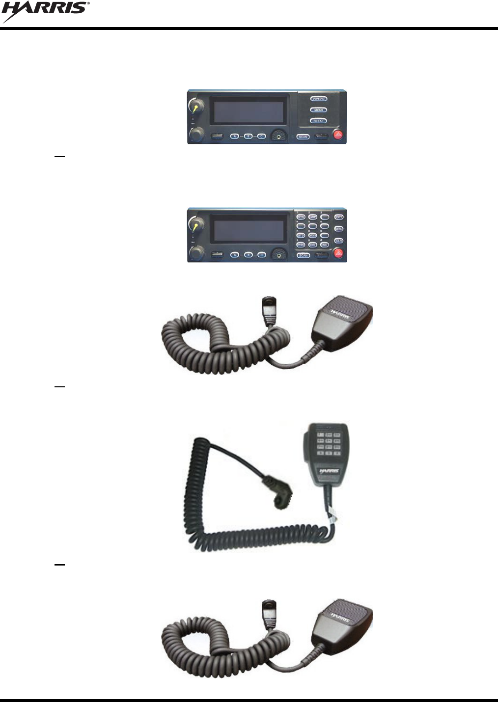
CH-721 Scan Control Head, part number CU23218-0002
(M5300 catalog number MAHK-NCP9E)
(M7300 catalog number MAMW-NCP9E)
or
CH-721 System Control Head, part number CU23218-0004
(M5300 catalog number MAHK-NCP9F)
(M7300 catalog number MAMW-NCP9F)
Standard Microphone, part number MC-101616-041
(Included with catalog numbers MAHK- NMC7Z and MAMW-NMC7Z)
or
DTMF Microphone, part number MC-103334-040
(Included with catalog numbers MAHK-NMC9C and MAMW-NMC9C)
or
Noise-Canceling Microphone, part number MC-103334-050
(Included with catalog numbers MAHK-NMC9D and MAMW-NMC9D)
MM-015371-001, Rev. C
22
4.3 INSTALLATION KITS
Four (4) Motorcycle Installation Kits are available for M5300 and M7300 motorcycle radio installations.
Two (2) are for M5300 motorcycle radio installations, and two (2) are for M7300 motorcycle radio
installations. The kits are listed in the following table:
Table 4-1: Motorcycle Installation Kits
for M5300/M7300 Mobile Radios with CH-721 Control Heads
CATALOG NUMBER DESCRIPTION
MAHK-NZN7X M5300 Motorcycle Installation Kit with Accessory Cable
MAHK-NZN7Y M5300 Motorcycle Installation Kit without Accessory Cable
MAMW-NZN7X M7300 Motorcycle Installation Kit with Accessory Cable
MAMW-NZN7Y M7300 Motorcycle Installation Kit without Accessory Cable
Table 4-2 below lists the contents of these installation kits. Contents are identical except MAHK-NZN7X
for the M5300 radio and MAMW-NZN7X for the M7300 radio both include Accessory Cable
19B802554P24, whereas the other two kits do not contain this cable. Accessory Cable 19B802554P24 is
required when making headset and/or portable radio connections as described in Section 11 of this
manual.
Table 4-4 on page 25 lists part numbers for radio-related options and accessories, and Table 4-5 on page
26 lists options and accessories available for the CH-721 Scan and System model control heads.
Table 4-2: Contents of M5300/M7300 Motorcycle Installation Kits
ITEM QTY. PART NUMBER DESCRIPTION ILLUSTRATION
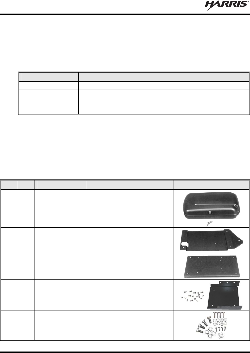
1 1
188D6464P1 Case, Weather-Resistant Motorcycle
Radio, Black, Lockable (supplied
with key)
2 1
188D6437P1 Bracket, Case/Antenna
3 1
188D6438P1 Bracket, Adapter
4 1
KT23117 Kit, Remote-Mount Radio Mounting
Bracket
5 1
350A1396G1 Kit, Hardware, for Motorcycle Radio
Case
MM-015371-001, Rev. C
23
Table 4-2: Contents of M5300/M7300 Motorcycle Installation Kits
ITEM QTY. PART NUMBER DESCRIPTION ILLUSTRATION
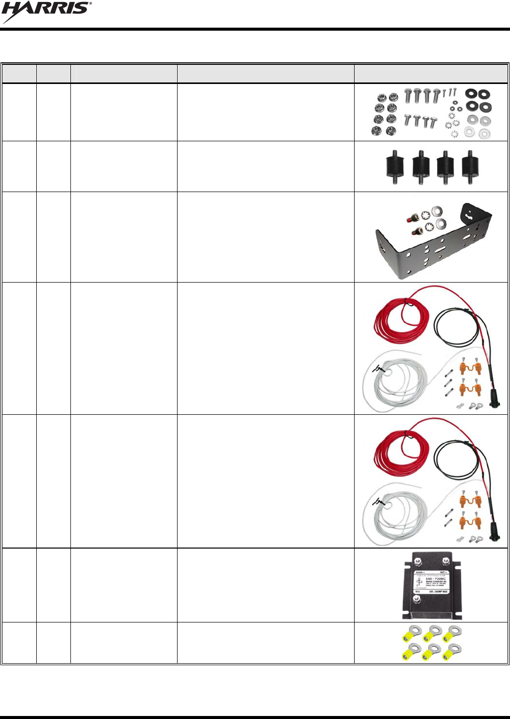
6 1
350A1396G2 Kit, Hardware, for Motorcycle Radio
Case, Brackets, and Antenna.
7 1
350A1396G4 Kit, Hardware, Motorcycle Adapter
Bracket Mounting (4 shock mounts).
8 1
KT-008608 Kit, CH-721 Mounting Bracket.
Includes (1) U-Shaped Mounting
Bracket FM24841-0001, (2) ¼-Inch
#8-32 stainless-steel screws, (2)
stainless-steel flat washers and (2)
stainless-steel lockwashers.
9 1
CA-012365-001 Cable, M7200/M7300/M5300 DC
Power. Includes (1) 20-Foot DC
Power Cable with straight connector,
(2) waterproof inline HFB-type fuse
holders, (1) 3-amp AGC fuse, (1)
15-amp AGC fuse, and (1) 20-amp
AGC fuse.
10 1
CA-012616-001 Cable, CH-721 DC Power. Includes
(1) DC Power Cable with straight
connector, (2) waterproof inline HFB-
type fuse holders, (1) 3-amp AGC
fuse, and (1) 5-amp AGC fuse. This
DC Power Cable has a 10-foot
12-AWG red wire (main power input),
a 20-foot white wire (switched power
input), and a 5-foot black wire
(ground).
11 1
19A703965P2 Filter, Alternator Whine Reject.
12 6
2-320568-2 Terminal, Ring, 12 to 10 AWG,
Insulated.
(Cont.)
MM-015371-001, Rev. C
24
Table 4-2: Contents of M5300/M7300 Motorcycle Installation Kits
ITEM QTY. PART NUMBER DESCRIPTION ILLUSTRATION
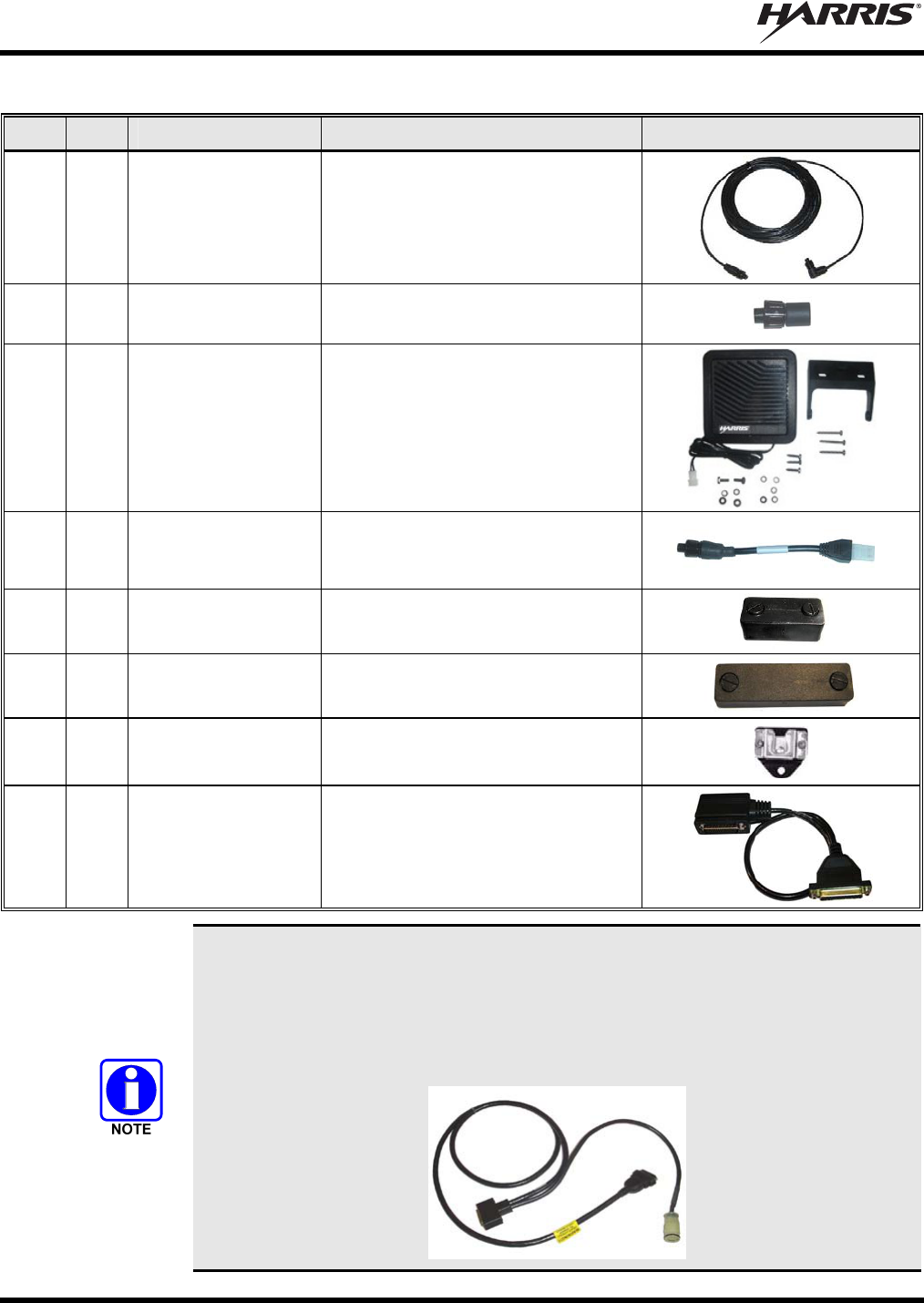
13 1
CA-009562-030 Cable, CAN; 30 feet, Right-Angle
and Straight Connectors
14 2
CD-014027-001 Terminator, CAN; 3-Pin
15 1
LS102824V10 Speaker, External Mobile; 20-Watt
(with 4.6-foot cable)
16 1
MAMROS0034-
NN006
Cable, Speaker; 6-Inch, Straight
Connector
17 1
FM-104859-001 Cap, Waterproof (For CH-721’s DB-9
serial port connector)
18 1
FM-104859-002 Cap, Waterproof (For CH-721’s
DB-25 accessory connector)
20 1
188D6556G1 Hanger, Microphone
21 1
CA-012349-002 Cable, Headset Adapter (Required
when Accessory Cable
19B802554P24 is used. For
additional information, see the NOTE
that follows and Section 11.)
In addition to the items listed in Table 4-2, Motorcycle Installation Kit MAHK-NZN7X
for the M5300 radio and Motorcycle Installation Kit MAMW-NZN7X for the M7300
radio also include Accessory Cable 19B802554P24 (image shown below). When used
with the M5300 and M7300 mobile radios, this cable provides connections for a
headset and/or portable radio; see Section 11 for additional information. In other
applications, it also supports connections to an external siren and light system:
MM-015371-001, Rev. C
25
4.4 ANTENNAS
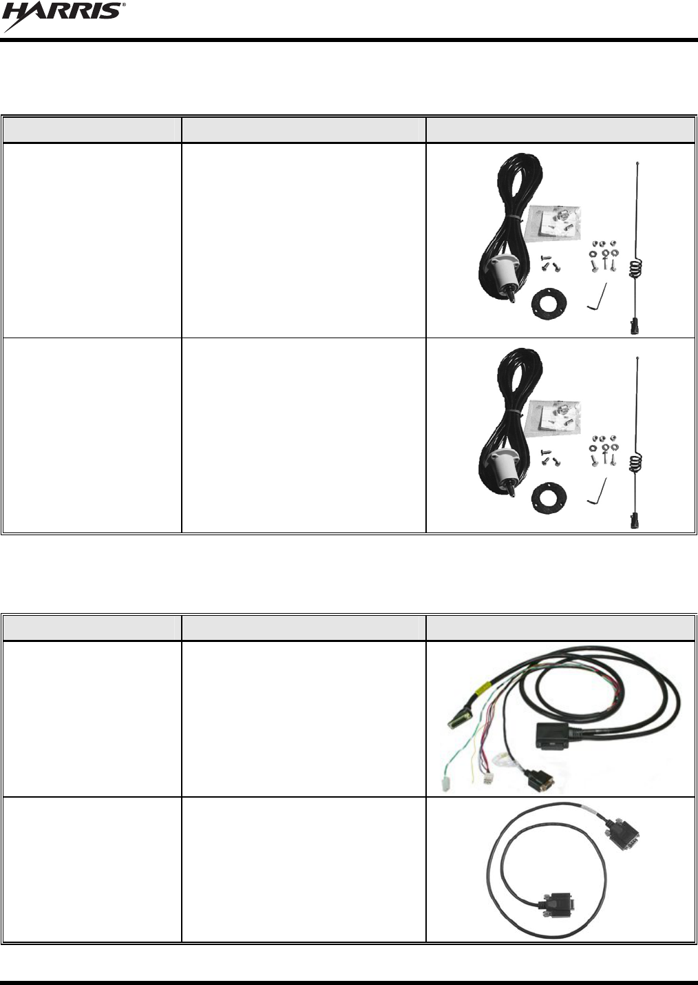
Table 4-3: Antennas for Motorcycle Applications of the M5300 and M7300 Mobile Radios
PART NUMBER DESCRIPTION ILLUSTRATION
LE-OM150K.125/TNC Antenna, 136 to 174 MHz High-
Impedance Voltage/End-Fed;
2.5 dBd Gain
LE-OM806HDBKTNCDS Antenna, 800 MHz High-Impedance
Voltage/End-Fed
4.5 OPTIONS AND ACCESSORIES
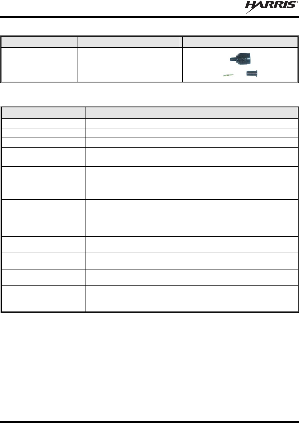
Table 4-4: Additional Options and Accessories for M5300 and M7300 Mobile Radios
PART NUMBER DESCRIPTION ILLUSTRATION
CA-012349-001 Cable, M5300/M7300 Option. See
Section 13.1 (page 60)
CA-013671-010
(10 feet long)
or
CA-013671-020
(20 feet long)
Cable, TIA/EIA/RS-232 Serial
Programming (See page 63 for
additional information.)
MM-015371-001, Rev. C
26
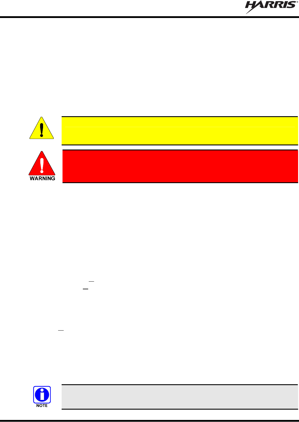
Table 4-4: Additional Options and Accessories for M5300 and M7300 Mobile Radios
PART NUMBER DESCRIPTION ILLUSTRATION
CN-014756 Connector, RF; TNC Male Crimp-
Type for RG58U, RG58A/U and
RGU400 Coaxial Cable
Table 4-5: Options and Accessories for CH-721 Control Heads
PART NUMBER DESCRIPTION
CA-009562-006 Cable, CAN; 6 feet, Right-Angle and Straight Connectors
CA-011854-001 Cable, CH-721 Option
CA-104861 Cable, CH-721 Programming
MAMROS0075-N1210 Cable, DC Power; 12-AWG, 10-Foot, Straight Connector
MAMROS0075-R1210 Cable, DC Power; 12-AWG, 10-Foot, Right-Angle Connector
MACDOS0012 Kit, Control Head Pedestal Mounting. Includes Pedestal Mount and Mounting
Screws.
MACDOS0013-CN004 Kit, Speaker; 20-Watt. Includes 6-Inch Cable MAMROS0034-NN006 (Straight
Connector)
MC-101616-040
(Discontinued; replaced by
MC-101616-041)
Microphone, Standard with Conxall Flush-Mount 45-Degree Connector
MC-101616-041 Microphone, Standard with Conxall Flush-Mount 90-Degree Connector
(Included with catalog numbers MAHK-NMC7Z and MAMW-NMC7Z)
MC-103334-040 Microphone, DTMF with Conxall Flush-Mount 45-Degree Connector
(Included with catalog number MAHK-NMC9C and MAMW-NMC9C)
MC-103334-041
(See footnote 5)
Microphone, DTMF with Conxall Flush-Mount 90-Degree Connector
MC-103334-050 Microphone, Noise-Canceling with Conxall Flush-Mount 45-Degree Connector
(Included with catalog numbers MAHK-NMC9D and MAMW-NMC9D)
MC-103334-051
(See footnote 5)
Microphone, Noise-Canceling with Conxall Flush-Mount 90-Degree Connector
344A4678P1 Microphone Hanger (One included with each microphone catalog option)
5 As of the publication of this manual, microphones MC-103334-041 and MC-103334-051 are not available. These two
mics have 90-degree connectors (also called “straight connectors”). See Section 3.3 for additional information.

MM-015371-001, Rev. C
27
Table 4-6: Headset-Related Options for Use with M5300 and M7300 Mobile Radios
CATALOG NUMBER DESCRIPTION
SM-KA-13 Kit, Helmet Headset, External-Mount with One Speaker and Noise-Canceling
Microphone
SM-KA-23 Kit, Helmet Headset, External-Mount with Two Speakers and Noise-Canceling
Microphone
SM-KA11-FG Kit, Half-Helmet Headset, Seer 1608, with One Speaker and Noise-Canceling
Microphone
SM-KA21-FG Kit, Half-Helmet Headset, Seer 1608, with Two Speakers and Noise-Canceling
Microphone
SM-MCK-71GT Cable, Headset Helmet Kit Interface, with Pushbutton PTT Switch (Kawasaki®)
SM-MCK-72GT Cable, Headset Helmet Kit Interface, with Rocker PTT Switch and Channel Guard
Disable Switch (Kawasaki)
SM-MCH-71GT Cable, Headset Helmet Kit Interface, with Pushbutton PTT Switch (Harley-
Davidson®)
SM-MCH-72GT Cable, Headset Helmet Kit Interface, with Rocker PTT Switch and Channel Guard
Disable Switch (Harley-Davidson)
SM-MCH-73GT Cable, Headset Helmet Kit Interface, with Rocker/PTT/PA Switch and Channel
Guard Disable Switch (Harley-Davidson)
SM-25-0694 Cable, Extender, Helmet to Harness
SM-CA-3G5 Assembly, Belt Box Cable, JAGUAR™ 700P/Pi and P7100IP
SM-CA-3GY Assembly, Belt Box Cable, LPE-200™
SM-CA-3GV Assembly, Belt Box Cable, M-RK™
CA-012349-002 Cable, Headset Adapter
19B802554P24 Cable, Accessory
4.6 MATERIALS NOT SUPPLIED
The following is a non-inclusive list of typical materials that are not supplied with a standard radio
equipment package, but will be required to complete the radio installation:
Motorcycle’s Radio Bracket (sometimes referred to as an “Interface Bracket”) — Typical type shown
in Figure 5-2.
Control Head’s Adapter Bracket — See Figure 8-4
Miscellaneous Hardware for Securing Brackets to Motorcycle
Nylon Wire/Cable Ties
MM-015371-001, Rev. C
28
5 PLANNING THE INSTALLATION
5.1 GENERAL INFORMATION
Figure 5-1 on page 29 illustrates a typical M5300/M7300 mobile radio motorcycle installation. Before
starting, plan the installation carefully so it will:
Be safe for the motorcycle operator;
Allow convenient access by the operator, as applicable (i.e., the control head);
Neat; and,
Allow easy service access.
CAUTION
A professional radio installer should perform the installation!
Mounting of the mobile radio components in ways other than those described in
this manual may adversely affect performance, violate FCC rules on RF exposure,
and even damage the unit(s), posing a potential safety hazard.
5.2 RECOMMENDED TOOLS
The following tools are recommended to complete the installation. Where specific vendor names and
model or part numbers are presented, equivalent substitutes may be used:
Non-Insulated Crimp Tool with Wire Cutter
similar to Thomas & Betts WT-111-M
Insulated Terminal Crimp Tool with Wire
Cutter similar to Klein 1005
Fuse Holder Crimp Tool similar to Thomas
& Betts – WT-112M or California Terminal
Products No. 1250 or Channelock No. 909
Ratcheting Hex-Crimp Tool for 50-Ohm
TNC and BNC RF Connectors and RG-58
Cable similar to Tyco Electronics 58433-2
(includes Crimper 354940-1 and Die Set
58436-1) or Cambridge 24-9960P
Metric and S.A.E. Socket Set with Sockets
to at least ½-Inch, a Nut Driver and an
Extension at least 3-Inches Long
Soft-Jaw Pliers similar to Tessco 450520 or
equivalent
Torx Screwdrivers, T10 and T20
Phillips-Head Screwdrivers, #1 and #2
Flat-Blade Screwdrivers, #1 and #2
4-Millimeter Hex Key Wrench
⅛-Inch Hex Key Wrench (Allen Wrench)
Cordless Electric Drill(s) with Bits
Deburring Tool (for ⅜-inch and smaller
holes)
Tie Wraps: 6-inches or larger
Flush-Cut and Large Wire Cutters
Various Fasteners (e.g., machine screws and
nuts, Tek screws, etc.)
A separate list of test equipment is included in Section 15.2 on page 70.
MM-015371-001, Rev. C
29
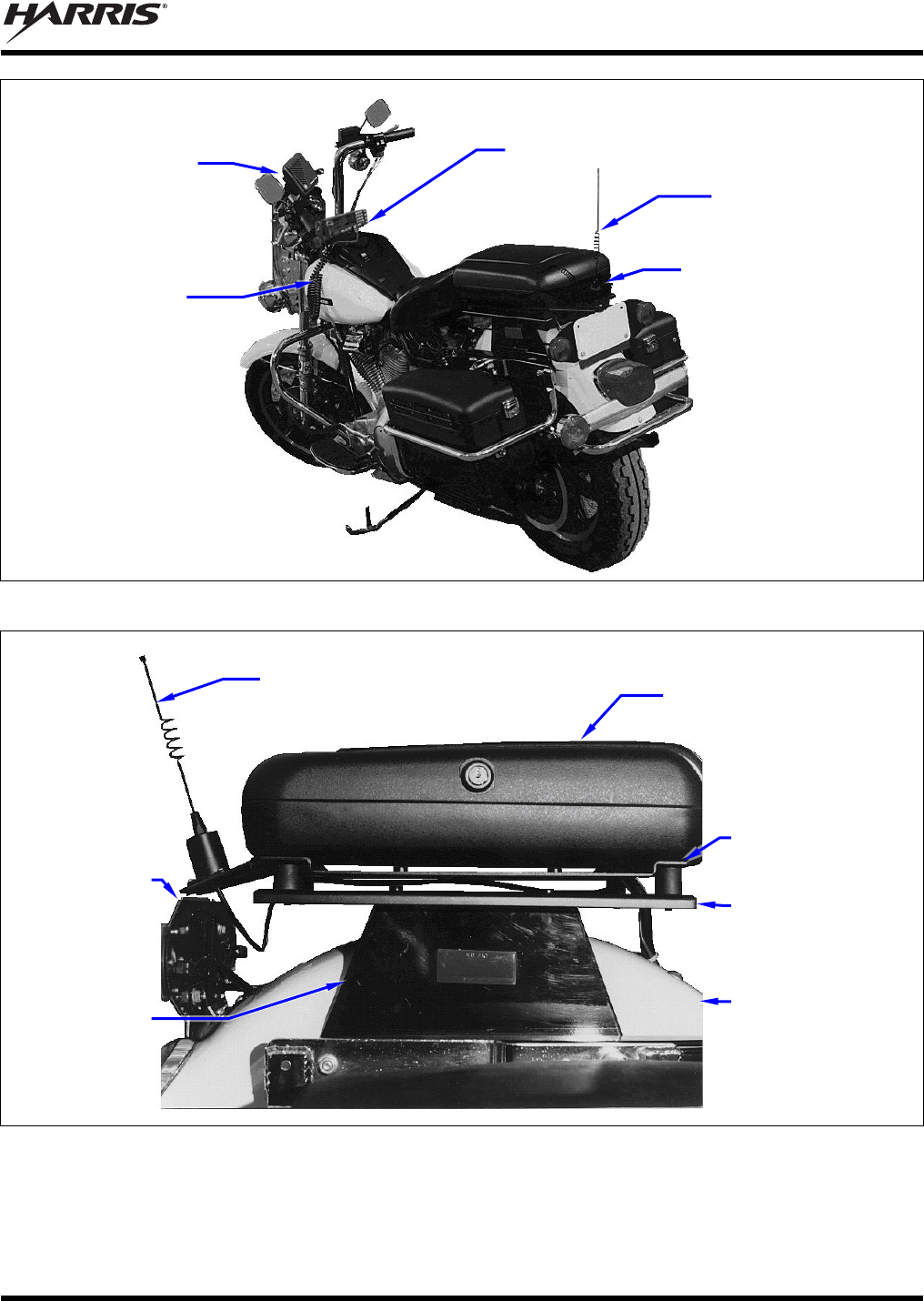
Figure 5-1: Typical Motorcycle Installation (Full View from Rear)
Figure 5-2: Typical Motorcycle Installation (Partial View of Radio Case and Brackets from Right Side)
Mobile
Antenna
CH-721
Control Head
Mobile
Speake
r
Weather-Resistant
Case with M7300
Mobile Radio Inside
Microphone
Mobile
Antenna
Weather-Resistant
Case with M7300
Mobile Radio Inside
Motorcycle’s
Rear License
Plate
Motorcycle’s
Rear Fender
(partial view)
Adapter Bracket
Case/Antenna
Bracket
Motorcycle’s
Radio Bracket
(not supplied)
MM-015371-001, Rev. C
30
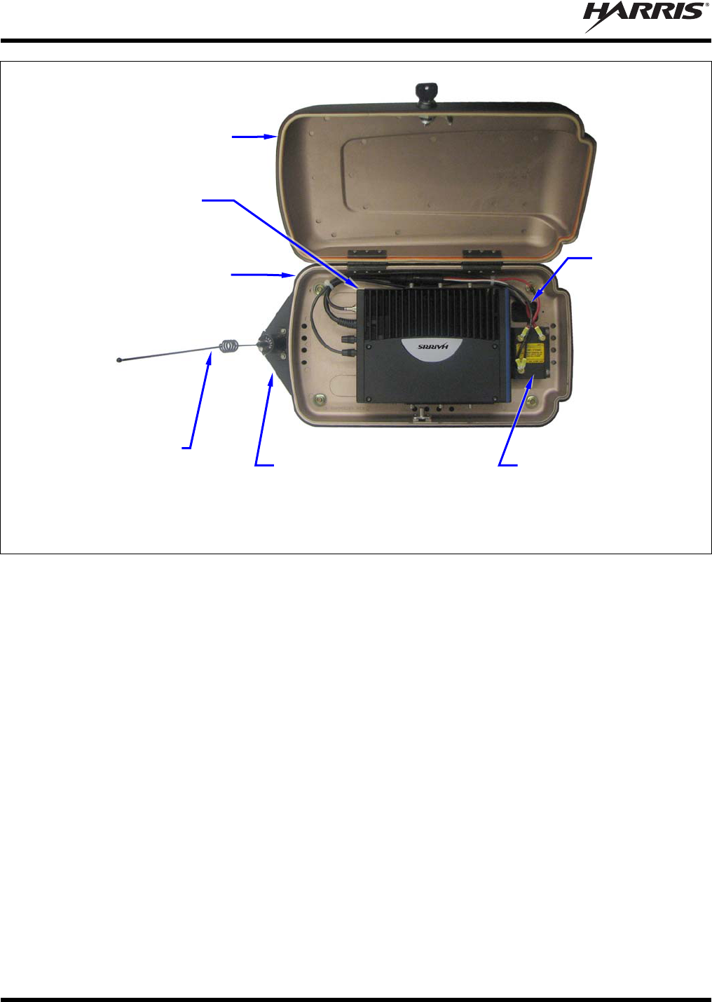
Figure 5-3: M5300/M7300 Mobile Radio inside Weather-Resistant Motorcycle Radio Case
Weather-Resistant
Case (Bottom)
Square hole
in bottom
floor of case
M7300 Mobile Radio
R
E
A
R
F
R
O
N
T
Weather-Resistant Case
(Top; Shown Opened)
Mobile Antenna Case/Antenna
Bracket
(Adapter Bracket Not Shown)
A
lternator Whine
Reject Filter
MM-015371-001, Rev. C
31
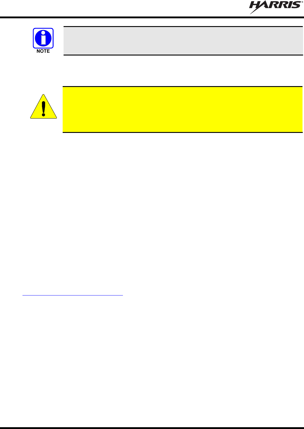
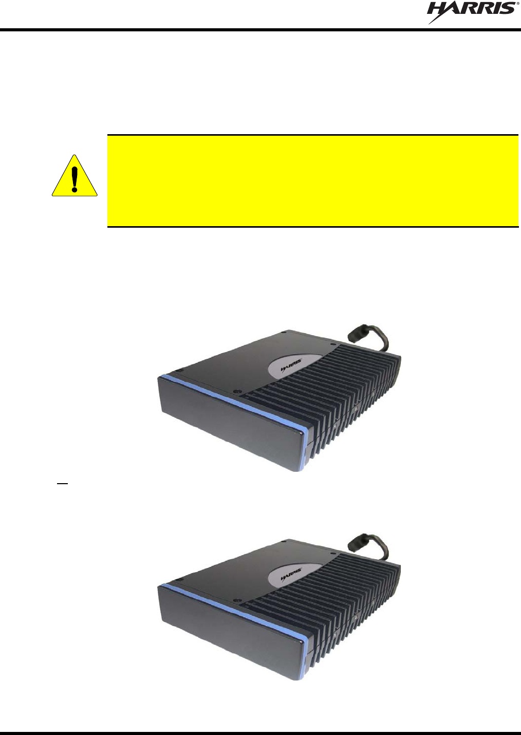
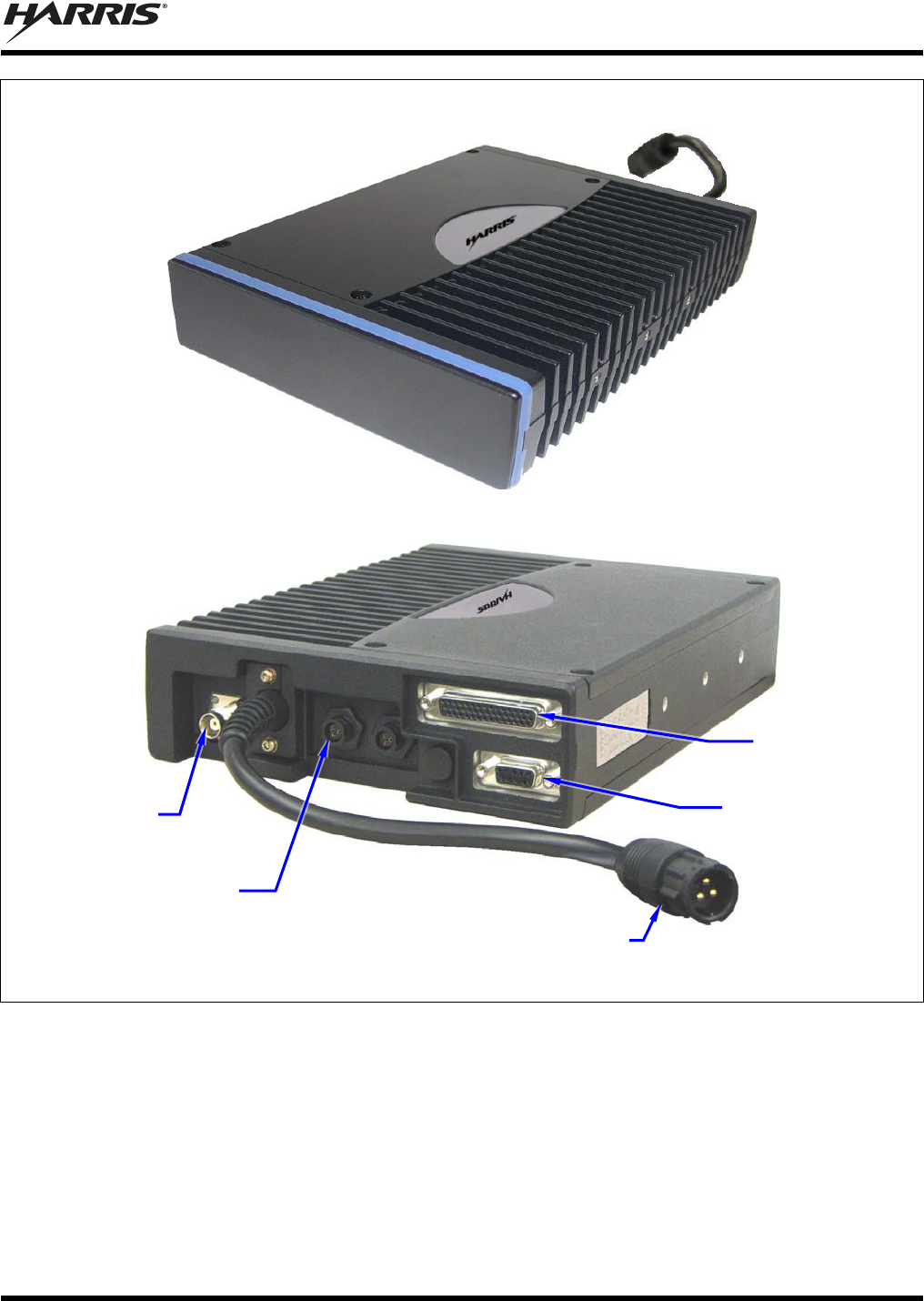
FRONT VIEW
REAR VIEW
Figure 5-4: M5300/M7300 Mobile Radio — Front and Rear Views (Radio Removed from Case)
5.3 LOCATING COMPONENTS
Plan the mounting locations of all components (radio, control head, antenna, and cables) and determine
the routes for all wiring and cables. Particularly consider the connection of the radio for planning
purposes.
The radio and its weather-resistant case must be mounted at the rear of the motorcycle, just above the
rear fender. The respective installation procedures are contained in Section 6 of this manual.
CAN Port Connectors
(2 places)
Antenna
Connector
(female TNC)
DC Power Cable
(with 3-Pin Connector)
44-Pin I/O
Connector
9-Pin Serial Port
Connector
MM-015371-001, Rev. C
32
The mobile antenna must be mounted at the rear of the motorcycle on the supplied case/antenna
bracket. For specific antenna installation-related information, refer to Section 7 of this manual.
The CH-721 control head must be mounted at the front of the motorcycle, on the handlebars. The
respective installation procedures are contained in Section 8 of this manual.
Radio and control head dimensions are listed in Section 2.1 on page 12. Several inches of clearance
space is required at the back of the control head.
For other mobile radio related components such as the microphone and speaker, determine the
customer’s preferences if any, for mounting locations. Comply with these preferences as long as they
are consistent with safety recommendations and guidelines presented in this manual, and other
generally accepted professional radio installation practices.
Verify the drilling of holes and the insertion of screws will not damage or interfere with any existing
vehicle components (for example, a fuel tank, fuel lines, the transmission housing, etc.), or any
existing vehicle wiring.
CAUTION
The radio must be kept out of direct sunlight and away from heat sources. Adequate
free-air ventilation must be provided to its rear fins. The radio will automatically reduce
its transmit RF output power when its ambient temperature exceeds approximately
+140° Fahrenheit (+60° Celsius).
CAUTION
All cables should have a service loop near each connector end. Do not bend the cables
at severe angles near the connector end. Above all, after all components are installed,
verify no cable is under any tension. Failure to do so may lead to damaged cables,
causing intermittent radio operation or complete radio failure.
CAUTION
Before drilling holes and/or installing mounting screws, verify these operations will not
damage or interfere with any existing vehicle components such as the fuel tank, a fuel
line, engine, transmission, wiring, etc. Always check to see how far the mounting
screws will extend below the mounting surface prior to installation. Always deburr
drilled holes before installing screws.
5.4 DC POWER CONSIDERATIONS
Careful consideration must be given to total direct current (DC) power drain on the motorcycle’s
electrical system (e.g., battery, alternator, wiring, etc.) The motorcycle may be equipped with additional
lights, light flashers, siren, public address (PA) system, etc. that, in addition to the mobile radio, place
additional drains on the system. Refer to Section 2 on page 12 for the applicable specifications.
CAUTION
Any DC input power provided to the radio shall be no higher or lower than
13.6 volts DC 10%. The DC input power should be free and clear of any AC noise or
DC spikes above 18 volts. If the vehicle cannot meet these requirements, then DC
conditioning will be required before any DC is connected to the radio. This includes
conditioning for both the radio’s main DC power input lead and for its switched ignition
sense power input. DC conditioning can be accomplished by a noise filter or DC
isolation equipment such as Harris part number FL-018314-001 or FL-018314-002, or
similar units equal specifications. Contact TAC for additional information.
MM-015371-001, Rev. C
33
6 RADIO MECHANICAL INSTALLATION
Unless otherwise noted, all installation procedures in this manual should be performed
in the order presented.
6.1 INSTALLING THE ADAPTER BRACKET
Install the Adapter Bracket by attaching it to the motorcycle’s radio bracket as follows:
1. Obtain Adapter Bracket 188D6438P1 (Item 3 in Table 4-2) included in the Motorcycle Installation
Kit.
2. Obtain the four (4) resilient mounts in Motorcycle Adapter Bracket Mounting Kit 350A1396G4 (Item
7 in Table 4-2).
3. As illustrated in Figure 6-1, attach a resilient mount to each corner of the bracket using four of the
eight 5/16-inch serrated nuts included in Hardware Kit 350A1396G2 (Item 6 in Table 4-2). Use each
mount’s shortest stub. Tighten these four (4) nuts securely. A torque of approximately 100 in.-lbs.
(11.3 N.m.) is recommended.
The Adapter Bracket’s four (4) large PEM nuts must face up and its smaller PEM nut
must face down. Also, the small PEM nut must be towards the left-rear of the
motorcycle.
4. Using Figure 6-1 and/or Figure 6-2 as a guide, securely attach the Adapter Bracket to the
motorcycle’s radio bracket. Use the ¼-20 x ⅝-inch-long bolts (“hex cap screws”) and ¼-inch
flatwashers included in Hardware Kit 350A1396G2.
Some motorcycle radio brackets have pre-drilled holes that will match the four (4) PEM nuts in the
Adapter Bracket. In this case, as illustrated in Figure 6-1, use a ¼-inch flatwasher with each ¼-20 bolt
and first pass each bolt through the bracket hole, then into the respective PEM nut in the Adapter
Bracket.
Other motorcycle radio brackets have pre-installed PEM nuts that match holes (without PEM nuts) in
the Adapter Bracket. In this case, as illustrated in Figure 6-2, use ¼-inch washers with each ¼-20 bolt
and first pass each bolt through the respective hole in the Adapter Bracket, then into the respective
PEM nut in the motorcycle’s radio bracket.
5. Tighten all four ¼-inch bolts securely. A torque of between 55 and 60 in.-lbs. (6.2 to 6.8 N.m.) is
recommended.
6.2 MOUNTING THE CASE AND CASE/ANTENNA BRACKET TO
ADAPTER BRACKET
Mount the motorcycle radio case and the case/antenna bracket to the adapter bracket as follows:
1. Obtain Motorcycle Radio Case 188D6464P1 (Item 1 in Table 4-2) from the Motorcycle Installation
Kit.
2. Obtain Case/Antenna Bracket 188D6437P1 (Item 2 in Table 4-2) from the Motorcycle Installation
Kit.
3. Set the Case/Antenna Bracket onto the 5/16-inch studs of the four (4) resilient mounts. These mounts
were attached to the Adapter Bracket in the previous procedure. Pass the studs through the oval-
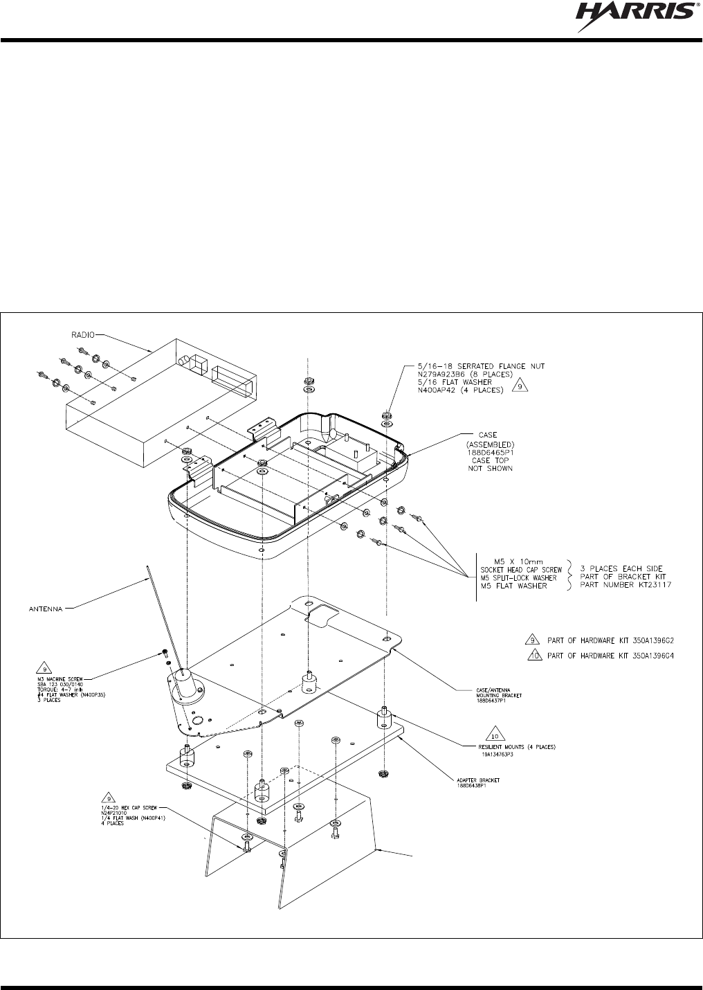
MM-015371-001, Rev. C
34
shaped holes in the corners of the Case/Antenna Bracket. The bracket’s triangle-shaped antenna
mounting surface must face to the rear of the motorcycle.
4. Open-up the case to expose the interior floor in its bottom-half.
5. As illustrated in Figure 6-1, place the case over the Case/Antenna Bracket, and onto the 5/16-inch
studs, passing the studs through the holes in the floor of the case. The square hole in the bottom floor
of the case must be towards the front of the motorcycle, so it is directly over the square hole in the
Case/Antenna Bracket.
6. Place a 5/16-inch stainless-steel flatwasher onto each of the four 5/16-inch studs protruding through the
holes in the floor of the case. These flatwashers are included in Hardware Kit 350A1396G2 (Item 6 in
Table 4-2).
7. Add four 5/16-inch serrated nuts to the studs (each nut’s washer side down), and tighten all four nuts
securely. A torque of approximately 100 in.-lbs. (11.3 N.m.) is recommended.
MOTORCYCLE’S RADIO BRACKET
(NOT SUPPLIED)
(Made From AA01-MAMV, Sh. 2, Rev. -)
Figure 6-1: Assembling, Mounting and Installing the Radio Case and Brackets
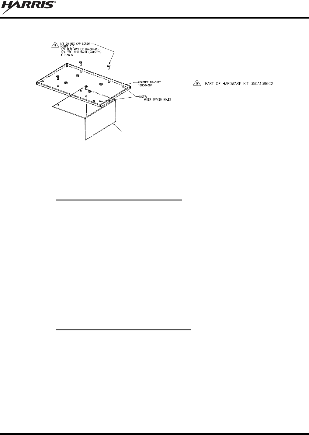
MM-015371-001, Rev. C
35
MOTORCYCLE’S RADIO BRACKET
(NOT SUPPLIED)
(Made From AA01-MAMW, Sh. 2, Rev. -)
Figure 6-2: Alternate Mounting for Adapter Bracket
6.3 INSTALLING THE RADIO IN THE CASE
6.3.1 Install the Radio’s Mounting Bracket
Install the radio’s mounting bracket into the weather-resistant motorcycle radio using the following
procedure. Also refer to Figure 6-3 as necessary:
1. Obtain Radio Mounting Bracket FM103111V1 from Remote-Mount Radio Mounting Bracket Kit
KT23117 (Item 4 in Table 4-2).
2. If not already, open-up the case to expose the interior floor in the bottom-half of the case.
3. Position the bracket on the case’s interior floor, at its mounting location. The large notches in the
sides of the bracket must be positioned towards the front of the case. (Some early brackets did not
have these notches.) The square hole in the floor is towards the front.
4. Secure the bracket to the case’s floor using four M6 x 14 mm bolts and four external-tooth
lockwashers included in Hardware Kit 350A1396G1 (Item 5 in Table 4-2).
5. Tighten these four bolts securely. A torque of between 45 and 65 in.-lbs. (5.1 to 7.3 N.m.) is
recommended.
6.3.2 Install the Radio into Mounting Bracket
Install the radio into its mounting bracket as follows:
1. Lay the radio down into the mounting bracket with its front surface towards the front of the case. This
positions the connectors on the rear panel of the radio towards the rear of the case and motorcycle.
See Figure 5-3 and Figure 5-4 on pages 30 and 31.
2. Attach the radio to the bracket using the six (6) M5 x 10 mm stainless-steel socket-head screws, and
flatwashers and lockwashers included with the Remote-Mount Radio Mounting Bracket Kit KT23117
(item 4 in Table 4-2). See Figure 6-1.
3. Tighten all six screws using a 4-millimeter hex key wrench until each lockwasher is fully compressed
and the radio is firm and flush in between the brackets.
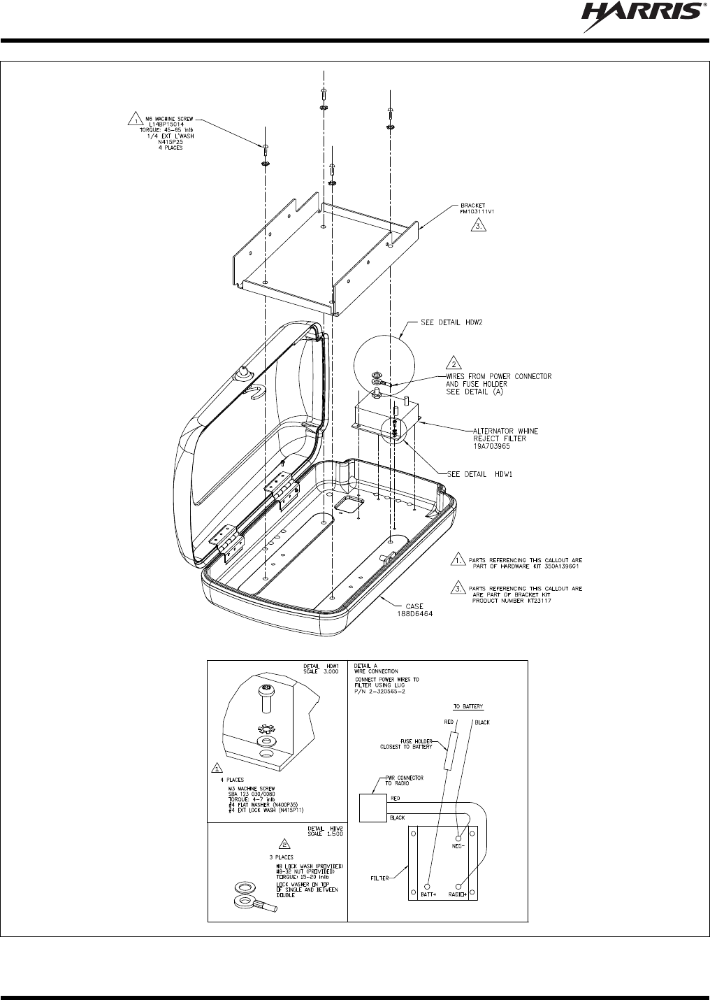
MM-015371-001, Rev. C
36
DETAIL VIEWS
(Made From AA01-MAMW, Sh. 1, Rev. –)
Figure 6-3: Installing the Radio’s Mounting Bracket and Filter into the Motorcycle Radio Case
MM-015371-001, Rev. C
37
7 ANTENNA INSTALLATION
7.1 MOBILE ANTENNA INSTALLATION
7.1.1 Install the Mobile Antenna
Table 4-4 (page 25) lists the mobile antenna available for M5300 and M7300 mobile radio motorcycle
installations. This antenna is a voltage/end-fed high-impedance antenna that provides the proper VSWR
and radiation pattern without the use of a ground plane. Typical antenna gain without a ground plane is 0
dBd.
The following mobile antenna installation procedure is recommended:
1. Review the information presented in Section 1.2 (page 6), taking note of the Recommended
Minimum Safe Lateral Distance for Controlled Environments presented in Table 1-1 (page 8).
2. Verify the antenna’s mounting location on the triangular-shaped end of the Case/Antenna Bracket
places the motorcycle operator outside of the Minimum Safe Lateral Distance for Controlled
Environments. If it does not, the bracket(s) must be repositioned on the motorcycle. If necessary,
contact the Technical Assistance Center. See page 19 for TAC contact information.
3. Mount the antenna in accordance with the instructions supplied with it.
4. Calculate the required antenna coax cable length using the information presented in the following
section.
Since the antenna is a high-impedance, voltage/end-fed antenna, the length of the
coaxial cable from the base of the antenna to the radio’s TNC antenna connector
is critical. It cannot be an arbitrary length. To prevent possible extraneous radiation,
high VSWR, RFI feedback from the antenna to the radio, or antenna ground currents,
select an antenna coaxial cable length that is close to a multiple of an odd quarter-
wavelength. Refer to the following information for details on calculating the correct
cable length.
7.1.2 Calculating the Antenna Cable Length
Typically, an antenna coax cable length of at least 32 inches will be required to reach from the base of the
antenna to the TNC RF antenna connector at the rear of the radio. This length includes appropriately 6
inches for a service loop inside the case. To calculate the proper antenna coax cable length, proceed as
follows:
1. Determine the center frequency of the majority of programmed transmit channel frequencies.
2. Use the following formula to calculate the ¼-wavelength, in inches:
MHzinFrequency
inchesin 2805
¼
Example: Assume the customer has a radio with all transmit frequencies between 816 and 821 MHz.
Therefore, the center frequency is 818.5 MHz. Applying the above formula results in:
5.818
2805
¼inchesin
= 3.43 inches
3. Calculate the ½-wavelength by multiplying the ¼-wavelength by 2:
Example: = 3.43 x 2 = 6.86 inches
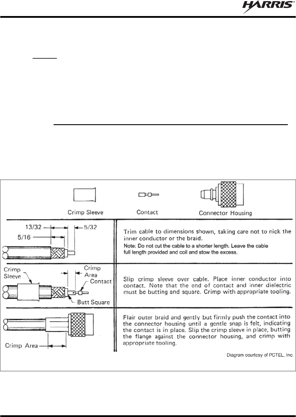
MM-015371-001, Rev. C
38
4. Pick a value of N then use the following formula to calculate an antenna cable length that will result
in a cable length long enough for the installation:
(N x ½ in inches + ¼ in inches) x 0.66 = required cable length in inches
Example: Choose N = 7. Therefore, the cable length in inches calculates to be:
(7 x 6.86 inches + 3.43 inches) x 0.66 = 33.96 inches
5. Verify the calculated cable length is long enough to route it from the base of the antenna, into the
radio’s weather-resistant case, to the TNC RF connector on the rear of the radio, leaving some cable
length for a service loop. If not, recalculate the length per the formula in the previous step, using a
greater value of N.
6. Shorten the cable by cutting it to the calculated length.
7.1.3 Route Cable, Crimp-On TNC RF Connector and Connect It to the Radio
1. Route the antenna coax cable from the base of the antenna to the radio’s weather-resistant case.
2. Route the cable into the case by passing it through the hole in the bottom of the case.
3. Outside the case, tie and stow the cable.
4. Using an appropriate crimp tool, crimp the supplied TNC RF connector to the end of the antenna
cable. For crimping instructions, see Figure 7-1 or the instructions supplied with antenna.
Actual Size; Dimensions are in Inches
(VS-AN-025167-010 Rev. A)
Figure 7-1: Crimping Instructions for TNC RF Connector
5. The antenna cable is connected to the radio’s TNC receptacle-type (female) RF connector per a
procedure presented later in this manual. The cable and its TNC connector must be protected from

MM-015371-001, Rev. C
39
damage, dirt, and/or metal shavings which may be generated during the mechanical and electrical
installation of the radio. Temporarily tying the connector and cable-end within a small plastic bag is
recommended.
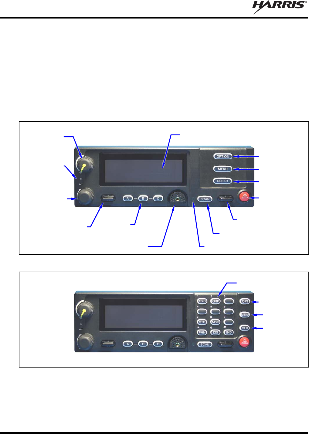
MM-015371-001, Rev. C
40
8 CONTROL HEAD MECHANICAL INSTALLATION
8.1 GENERAL INFORMATION
The radio must be connected to a control head to provide the operator-to-radio interface. Two different
control heads are available — the CH-721 Scan model and the CH-721 System model. See Figure 8-1 and
Figure 8-2 respectively. The CH-721 Scan model control head features three (3) large menu selection
buttons. The System model control head has a 12-button keypad to allow advanced operations without the
need of a DTMF-capable microphone.
Figure 8-3 on page 41 illustrates the rear panel of the two control head models. Both models have
identical rear panels and rear panel connectors.
Figure 8-1: CH-721 Scan Model Control Head Front Panel
(Other controls are same as shown for Scan model.)
Figure 8-2: CH-721 System Model Control Head Front Panel
The CH-721 control heads feature a large easy-to-read 3-line graphical vacuum fluorescent display, an
on/off/volume control knob, menu controls and buttons, trunking mode buttons, an emergency/home
button, a scan on/off/volume control, and three (3) preset buttons. Other front panel components include a
microphone connector and LED-type indictors. One LED indicator is the busy indicator that lights when
3-Line Graphical Vacuum
Fluorescent Display
Microphone Connecto
r
On/Off/
Volume
Control
System/
Group/
Channel
Selection
Control
/ Ramp Control
Preset/
Softkey
Buttons
Emergency/
Home Button
+/- Ramp Control
Ambient Light-Level Sensor
Transmit
and Busy
Indicators
Scan On/Off Button
Clear Button
Menu Button
Option Button
12-Button Keypad
Clear Button
Menu Button
Option Button
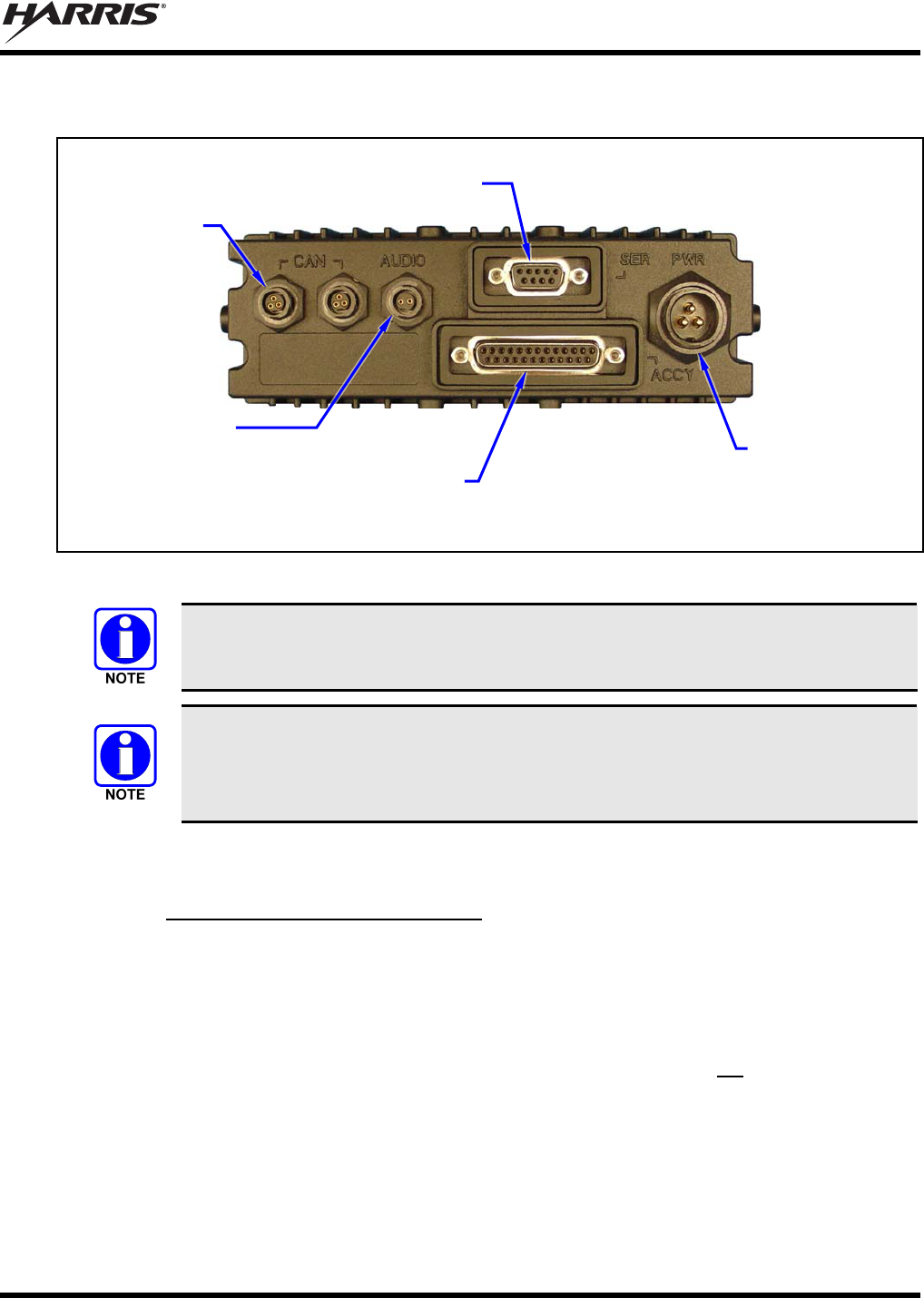
MM-015371-001, Rev. C
41
the radio is receiving a call and one is the transmitter-enabled indicator that lights when the radio is
transmitting. The front panel also has an ambient light sensor for automatic display dimming.
Figure 8-3: CH-721 Rear Panel (both control head models)
Prior to installing the control head, verify it has the proper software version installed and
verify it has been properly configured for customer use.
Because an installation kit contains the most complete set of materials for installing the
radio and control head, the following instructions make repeated reference to items
within a kit. References to item numbers refer to items in a kit as listed in Table 4-2 on
page 22.
8.2 MOUNTING THE CONTROL HEAD
8.2.1 Selecting a Mounting Location
Typically, the CH-721 control head is mounted at the centerline of the motorcycle between the steering
handlebars, and secured to the handlebars or to the frame just below the handlebars. A typical installation
is shown in Figure 8-4. The CH-721 control head can be mounted using either the standard U-shaped
mounting bracket or the optional mounting pedestal. See Figure 8-4 and Figure 8-5 respectively. The
selected mounting location must:
Be safe for the motorcycle operator (e.g., the head must be located so it does not interfere with
motorcycle steering or any other motorcycle controls);
Allow convenient access by the operator;
Be neat;
Include clearance for the microphone’s connector that mates to the mic connector on the front of the
head;
Include clearance for the connectors/cables that mate to the connectors on the rear of the head; and,
CAN Port
Connectors
(2 places)
Speaker Audio
Connecto
r
Serial Port Connecto
r
(DB-9)
DC Power
Connector
Accessory Connecto
r
(DB-25) Note: Serial and Accessory connectors are
shown without waterproof covers.
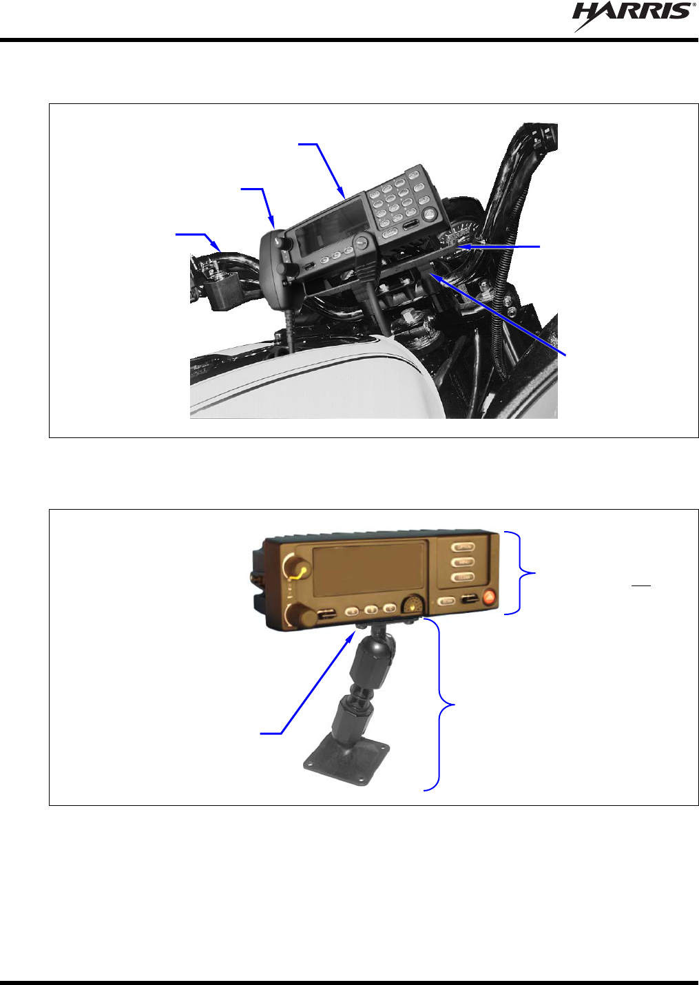
MM-015371-001, Rev. C
42
Have a relatively easy access for servicing.
Figure 8-4: Typical CH-721 Control Head Installation on a Motorcycle
(Using the Standard U-Shaped Mounting Bracket)
Figure 8-5: Optional Control Head Mounting Pedestal (Part Number MACDOS0012)
Due to the large number of different makes and models of motorcycles, it is the installer’s responsibility
to determine how to mount the control head and other related equipment such as the microphone hanger
and speaker.
CH-721 Control Head
Microphone
Motorcycle’s
Left Handleba
r
(Partial view)
Control Head
Adapter
Bracket
(Not Supplied)
Control Head
Mounting Bracket
FM24841-0001
(Included with
Mounting Bracket
Kit KT-008608)
Control Head Mounting
Pedestal MACDOS0012
(Pedestal can be attached to the
bottom of the head (as shown) or it
can be attached to the top of the
head.)
Pedestal shown
attached to a CH-721
Scan model control
head (Head is not
included with Mounting
Pedestal)
#8-32 Pan-Head Screw; 4
places (Included with
Mounting Pedestal)
For a “hanging” control head
installation, the pedestal can
be attached to the top of the
head via threaded holes in
the top of the head’s case.
This figure shows the
pedestal attached to the
bottom of the control head via
threaded holes in the bottom
of the case.
MM-015371-001, Rev. C
43
8.2.2 Control Head Adapter Bracket (Not Supplied)
In some cases, a control adapter bracket (not supplied) may be required to attach the supplied U-shaped
control head mounting bracket (or the optional mounting pedestal) to the motorcycle. Control head
adapter brackets for all makes and models are not available from the factory. Therefore, obtaining or
field-fabricating an adapter bracket will be required in some cases. All utilized bracketry:
Must be mounted in a location that is safe for the motorcycle operator (e.g., so it does not interfere
with steering and other motorcycle controls);
Must not interfere with the motorcycle operator’s visibility, including the view of all motorcycle
instruments;
Must provide a secure mount for the control head;
Must utilized rounded corners/edges to the maximum extent possible; and,
Must not be mounted in a way that compromises the strength of the motorcycle’s frame or other key
components.
Never comprise the strength of a motorcycle’s frame, handlebars, or other key
components by drilling or grinding holes in these components. Use clamps or
another method approved by the motorcycle manufacturer to attach radio
components.
CAUTION
Before drilling holes and/or installing mounting screws, verify these operations will not
damage or interfere with any existing vehicle components such as the fuel tank, a fuel
line, engine, transmission, wiring, etc. Always check to see how far the mounting
screws will extend below the mounting surface prior to installation. Always deburr
drilled holes before installing screws.
8.2.3 Mounting the CH-721 Control Head
8.2.3.1 Using the Standard U-Shaped Mounting Bracket
The following CH-721 control head mounting procedure is recommended:
1. Obtain CH-721 Mounting Bracket FM24841-0001 included in Mounting Bracket Kit KT-008608
(item 8 in Table 4-2).
2. Obtain or field-fabricate a suitable adapter bracket. Mount this bracket to the motorcyle according to
the manufacture’s instructions and/or industry-standard practices. Observe and follow the require-
ments listed in Section 8.2.2.
3. Using the CH-721 Mounting Bracket as a template, mark and drill mounting holes into the adapter
bracket as required. The round and elliptical holes in the mounting bracket’s mounting surface are
symmetrical, so forwards/backwards positioning is not important during this step. However,
positioning is important in the next step.
4. Postion the mounting bracket on the surface of the adapter bracket so the two round holes in its two
side “ears” are nearest to the normal location of the operator (towards the rear of the motorcycle) and
the two slotted holes are farthest from the normal location of the operator.
5. Attach the mounting bracket to the adapter bracket using suitable mounting hardware (not supplied).
The use of #12-24 stainless-steel self-locking hardware (i.e., machine screws with washers and self-
locking nuts) is recommended, in at least six (6) locations.

MM-015371-001, Rev. C
44
6. Verify the mounting bracket is held firmly mounted. Firm mounting prevents unreasonable vibration,
which could damage the control head and/or cause its cable connections to loosen.
7. Slide the control head into the bracket, placing the two pegs protruding from its left and right sides
into the respective round holes in the bracket’s two side “ears.”
8. In each side “ear” of the mounting bracket, start a #8-32 hex-socket-head cap (Allen) head screw with
a lockwasher and a flat washer by inserting the screw through the slotted hole in the bracket and then
into the threaded hole in the side of the control head. This hardware is included with Mounting
Bracket Kit. The lockwasher should be adjacent to the screw head and the flat washer should be
adjacent to the bracket. Turn each screw clockwise as observed from the head of the screw.
9. The control head can be positioned at various angles for best display viewing at the normal position
of the motorcycle operator. As necessary, turn it on the pegs to a good position and tighten both
screws using an ⅛-inch hex key (Allen) wrench until the control head is held firmly in place. Do not
over-tighten.
8.2.3.2 Using the Mounting Pedestal (Optional)
An optional Mounting Pedestal, part number MACDOS0012, may be purchased separately to replace the
standard U-shaped mounting bracket. This pedestal can be attached to the bottom of the control head as
shown in Figure 8-5, and then mounted to a mounting surface below the two. It can also be attached to the
top of the head and then mounted to a mounting surface above the two.

MM-015371-001, Rev. C
45
9 SPEAKER INSTALLATION
9.1.1 Selecting a Mounting Location
Typically, the radio’s speaker is mounted on the motorcycle’s steering handlebars. The selected mounting
location:
Must be in a location that is safe for the motorcycle operator (e.g., so it does not interfere with
steering and other motorcycle controls);
Must not interfere with the motorcycle operator’s visibility, including the view of all motorcycle
instruments;
Must allow for proper listening range with a moderate volume setting;
Must be mounted securely; and,
Must not be mounted in a way that compromises the strength of the motorcycle’s frame or other key
components.
9.1.2 Mounting the Speaker
The following mounting procedure is recommended:
1. Obtain External Speaker LS102824V10 (item 15 in Table 4-2) included in the installation kit.
2. Using the above listed guidelines, select a mounting location for the speaker.
3. Install the speaker using the hardware and mounting bracket supplied with it. In some case, an
appropriate adapter bracket will be required (not supplied).
4. Route the speaker cable to the rear of the CH-721 control head.
5. Mate the 6-inch speaker cable (item 16 in Table 4-2) to the 2-pin connector at the rear of the control
head by visually aligning the ¾-moon-shaped keys of the connectors, and then pushing and turning
the outer locking ring of the cable connector clockwise until it stops. A mild click will be sensed to
confirm proper mating.
6. Connect the speaker cable’s 2-pin plastic connector to the respective mating connector on the 6-inch
speaker cable.
7. Route the cables out of the way of casual contact. Tie and stow as necessary.
MM-015371-001, Rev. C
46
10 CABLE CONNECTIONS
10.1 DC POWER CONNECTIONS
10.1.1 Overview of On/Off Power Wiring Configurations
Radio on/off power control is accomplished by the control head. In a standard installation, when the
control head is turned on, it “wakes-up” the radio via data activity on the CAN link. The following power
wiring configurations are supported:
Radio turns on and off automatically with vehicle’s ignition switch/key — This configuration
allows the on/off state of the vehicle’s ignition switch/key to control the on/off power state of the
radio. The white wire of the control head’s DC Power Cable is connected to a fused switched power
source, typically identified as vehicle “Accessory” power. This source must switch on (up to positive
(+) battery voltage potential) when the vehicle’s ignition switch/key turns on, and it must switch off
(to near zero volts) when the ignition switch/key turns off. The required fuse rating is 3 amperes.
When using this configuration, the CH-721 control head’s on/off/volume control must be left in the
on position for automatic power-up/down to function properly.
A waterproof (HFB type) fuse holder and a 3-amp AGC fuse are included with the
control head’s DC Power Cable to fuse this cable’s white wire.
Radio turns on and off with a manual switch — This configuration is used when, for example, the
radio must remain on even when the ignition key must be removed from the vehicle and a separate
on/off switch is acceptable. The white wire of the control head’s DC Power Cable is connected to one
side of a manually-controlled switch, and the other side of this switch is connected to unswitched and
fused vehicle power. The required fuse rating is 3 amperes. When using this configuration, the
CH-721 control head’s on/off/volume control must be left in the on position for automatic power-
up/down to function properly.
Radio turns on with control head’s on/off/volume control (“hot wired”) — This configuration
allows radio on/off power control only via the control head’s on/off/volume control. It may be desired
if, for example, the radio must remain on even when the ignition key must be removed from the
vehicle and a separate on/off switch is not desired and/or not acceptable. The white wire of the
control head’s DC Power Cable must be connected to unswitched and fused vehicle power. The
required fuse rating is 3 amperes.
In all of the above cases, both the radio’s main DC power input (red wire) and the control head’s main
DC power input (also a red wire) must be connected to unswitched vehicle DC power (12-volts nominal)
via an Alternator Whine Reject Filter located in the motorcycle radio case. DC power supplied to this
filter is over-current protected by a fuse installed near the DC power source (i.e., near the motorcycle’s
positive battery terminal). The white ignition wire of the radio’s DC Power Cable is not used/not
connected in motorcycle applications.
10.1.2 Alternator Whine Reject Filter Installation
Install the Alternator Whine Reject Filter in the weatherproof radio case as follows:
1. Obtain Alternator Whine Reject Filter 19A703965P2 from the installation kit.
2. Using a T10 Torx screwdriver, mount the filter to the inside bottom floor of the radio case using the
four (4) stainless-steel M3 x 8-millimeter-long screws and M3 washers supplied in Hardware Kit
MM-015371-001, Rev. C
47
350A1396G1. As shown in Figure 5-3, position it so the two positive (+) studs are nearest the square
hole in the floor, and the ground stud is furthest from the hole. Tighten the screws securely.
CAUTION
Any DC input power provided to the radio shall be no higher or lower than
13.6 volts DC 10%. The DC input power should be free and clear of any AC noise or
DC spikes above 18 volts. If the vehicle cannot meet these requirements, then DC
conditioning will be required before any DC is connected to the radio. This includes
conditioning for both the radio’s main DC power input lead and for its switched ignition
sense power input. DC conditioning can be accomplished by a noise filter or DC
isolation equipment such as Harris part number FL-018314-001 or FL-018314-002, or
similar units equal specifications. Fusing must be placed in-line before any noise filter.
Contact TAC for additional information.
10.1.3 DC Power Cable and Main Fuse Holder Installation
The radio’s DC Power Cable has a 3-pin connector, a 20-foot red wire (for the main power connection), a
20-foot white wire (not connected), and a 4-foot black wire (for the ground connection). It is supplied
with waterproof fuse holders, two AGC-type fuses, and ring terminals. The following installation
procedures are recommended:
10.1.3.1 Black Wire Connection (Ground Wire)
1. Connect the radio’s DC Power Cable to the radio by mating its 3-pin connector to the radio’s 3-pin
power cable connector as follows: Visually align the key and firmly push and turn the outer locking
ring clockwise until it stops. A click will be sensed to confirm proper mating.
CAUTION
Do not confuse the radio’s DC Power Cable which has a 10-AWG red wire with the
control head’s DC Power Cable which has a 12-AWG red wire. The radio requires
much more DC operating current than the control head. Therefore, it requires the
larger wire size of 10-AWG. The part number of the radio’s DC Power Cable is
CA-012365-001.
2. Cut the white wire approximately three (3) inches from the cable’s connector, and insulate its end
using an approved method.
3. Route the cable’s black wire from the connector at the rear of the radio to the Alternator Whine
Reject Filter near the square hole in the bottom floor of the radio case. Leaving a service loop at the
rear of the radio, cut this wire to a length long enough to reach the ground stud on the filter. Save the
excess-length black wire to make the ground connection near the battery.
4. Strip approximately ¼-inch of insulation from both the end of the black wire from the cable connector
and one end of the excess-length black wire, then crimp a #8-stud ring terminal (has yellow
insulation) to each stripped wire end. These ring terminals are included with the Motorcycle
Installation Kit.
5. Remove the nut from filter’s ground stud (stud labeled “NEG”) and attach both ring terminals to this
stud. Reinstall the nut. It is not necessary to tighten the nut at this time, since a control head ground
wire will be added to this stud in a later procedure.
6. Route the excess-length black wire out of the square hole in the bottom floor of the radio case.
7. Prepare to connect this end of the black wire to vehicle ground by locating an area of metal within
approximately two (2) feet of the radio, and drilling a hole in it if necessary. This surface must have a
solid and stable connection to vehicle ground. If a new hole must be drilled, it should not be in a
MM-015371-001, Rev. C
48
structural part of the motorcycle’s frame, which could weaken the frame and cause it to crack. If
possible, use an existing hole to ground the black wire.
If an existing hole cannot be located, locate a non-structural metal area of the motorcycle that has a
solid and stable ground connection to the motorcycle’s frame. Drill a ⅜-inch hole in this metal area,
deburr it, and strip this area of all paint and dirt to expose a bare metal surface, approximately ¾-inch
square. A ⅜-inch-stud non-insulated ring terminal is supplied with the cable to make this ground
connection. Hole diameter must be appropriate for the utilized grounding screw/bolt size and type
used to connect the ring terminal to the bare metal surface. This hardware is not supplied.
Never comprise the strength of a motorcycle’s frame, handlebars, or other key
components by drilling or grinding holes in these components. Use clamps or
another method approved by the motorcycle manufacturer to attach radio
components.
8. Cut the excess-length black wire to the required length then strip insulation back approximately
¼-inch.
9. Crimp a ⅜-inch non-insulated ring terminal (supplied with the cable) to the end of the black wire,
crimp-on another terminal appropriate for the type of connection hardware being used.
10. Attach the ring terminal and black wire to the bare metal surface using stainless-steel self-locking
hardware (i.e., machine screws with washers and locking nuts) or other appropriate hardware to
ensure a reliable terminal-to-metal contact. Tighten securely.
11. Apply an approved paint or rust-inhibitor over the remaining exposed bare metal surface and around
the ring terminal.
10.1.3.2 Red Wire and Main Fuse Holder Connection (Radio’s Main Power Wire)
1. Route the cable’s red wire from the connector at the rear of the radio to the Alternator Whine Reject
Filter near the square hole in the bottom floor of the radio case. Leaving a service loop/slack at the
rear of the radio, cut this wire to a length long enough to reach the DC output stud (stud labeled
“RADIO +”) on the filter. Save the excess-length red wire to make the battery connection.
2. Strip approximately ¼-inch of insulation from both the end of the red wire from the cable connector
and one end of the excess-length red wire, then crimp a #8-stud ring terminal (has yellow insulation)
to each stripped wire end. These ring terminals are included with the installation kit.
3. Remove the nut from filter’s DC output stud (stud labeled “RADIO +”) and attach both ring terminals
to this stud. Reinstall the nut. It is not necessary to tighten the nut at this time, since a control head
power wire will be added to this stud in a later procedure.
4. Route the excess-length red wire out of the square hole in the bottom floor of the radio case.
5. Route the excess-length red wire to the location of the vehicle’s battery (or its main DC bus bar or
stud). Protect the wire from possible chafing where necessary. Tie and stow the wire as necessary.
CAUTION
Do not install any wiring or fuse holders over or in the near vicinity of the motorcycle’s
engine, or near other hot items such as exhaust pipes and mufflers. Excessive heat can
cause permanent damage to these components.
MM-015371-001, Rev. C
49
Before making connections to the battery’s positive post, carefully disconnect the
battery’s negative (ground) cable(s). This will prevent tools or other metallic
objects which come in contact with the battery’s positive terminal from shorting to
vehicle ground, causing sparks or even a fire or an explosion! When disconnecting
the negative cable(s), cover/insulate the positive post if it is not already so a tool
cannot short between the posts.
Radio and control head fuses should not be installed until all wiring is complete.
This will prevent the radio from powering up prematurely and/or causing an in-
rush of current that could lead to shorting of the battery, sparks, or even fire.
6. Obtain one of the waterproof (HFB type) fuse holders included with the DC Power Cable.
7. Observe and follow the previously presented WARNING!
8. Cut the red wire to the required length for connection to the battery’s positive (+) battery terminal (or
to the main DC bus bar or stud).
9. Prepare to splice the waterproof fuse holder into the red wire by cutting it again, at approximately
three (3) to six (6) inches from the end.
10. Strip all three (3) wire ends back approximately ⅜-inch, place a fuse holder shell on each wire, and
securely crimp a fuse holder terminal to each wire end. Before crimping, verify fuse holder shells are
oriented in the correct directions (i.e., with each large end towards the wire end).
11. Label this fuse holder and red wire appropriately (e.g., “Radio Main Power: 15-AMP FUSE”).
12. Do NOT install a fuse into the fuse holder at this time.
13. Crimp an appropriate electrical terminal to the short red wire. A corrosion-resistant ⅜-inch ring
terminal is included with the cable for this purpose, but another size corrosion-resistant terminal type
(not supplied) may be used if required.
14. Connect the ring terminal directly to the battery’s positive post (or if present, to a stud on the battery’s
main/non-switched power distribution terminal block).
CAUTION
When servicing the radio and/or control head, always manually power-down the radio
equipment via the control head’s on/off/volume control knob, and then remove the main
power fuse near the battery.
10.1.4 Control Head Power Cable Installation
Plan the route of the control head’s DC Power Cable carefully. Do not route the cable where it will be
damaged by heat sources or by casual contact, and protect it from wire chafe per standard installation
methods. The following procedures are recommended:
10.1.4.1 Install DC Power Cable and Make Power and Ground Connections
1. Connect the control head’s DC Power Cable (item 10 in Table 4-2) to the large 3-pin connector at the
rear of the head. Visually align the key and gently push and turn the outer locking ring clockwise until
it stops. A click will be sensed to confirm proper mating.
2. Protect the wires of this cable by inserting them into an appropriate-length high-temperature tubing,
loom or wrap (not supplied). Typically, a 4 to 5-foot length of tubing/loom/wrap is required.
3. Make a service loop in the cable near the back of the control head.
MM-015371-001, Rev. C
50
4. Route the cable (within the tubing/loom/wrap) to the frame of the motorcycle. If the control head is
mounted on the motorcycle’s handlebars, leave sufficient slack to allow for full handlebar
steering/travel without any stretching of the cable. This length of the cable must be in
tubing/loom/wrap. Tie and stow as necessary.
5. Route the cable to the radio case at the rear of the motorcycle and then pass it through the square hole
in the bottom floor of the case.
CAUTION
Do not install any wiring or fuse holders over or in the near vicinity of the motorcycle’s
engine, or near other hot items such as exhaust pipes and mufflers. Excessive heat can
cause permanent damage to these components.
6. Cut excess length from the red and black wires of the cable, leaving enough length for a service loop
inside the radio case, near the Alternator Whine Reject Filter. The red and black wires connect to two
(2) studs on the filter. The white wire is connected in the procedure that follows.
7. Strip approximately ¼-inch of insulation from the end of the black wire and crimp a #8-stud ring
terminal (has yellow insulation) to it. Ring terminals are included with the installation kit
8. Remove the nut from the filter’s ground stud (stud labeled “NEG”) and slip the ring terminal with the
black wire onto this stud. Three (3) black wires should be connected to this stud. Reinstall the nut
and tighten it securely. Recommended torque is 12 inch-pounds (1.36 Nm). Do not over-tighten the
stub nuts.
9. Strip approximately ¼-inch of insulation from the end of the red wire and crimp a #8-stud ring
terminal (has yellow insulation) to it.
10. Obtain one of the waterproof (HFB-type) fuse holders included with the control head’s DC Power
Cable.
11. Prepare to splice this waterproof fuse holder into the red wire by cutting it again, approximately three
(3) to six (6) inches from the end with the ring terminal.
12. Strip both wire ends back approximately ⅜-inch, place a fuse holder shell on each wire, and securely
crimp a fuse holder terminal to each wire end. Before crimping, verify fuse holder shells are oriented
in the correct directions (i.e., with each large end towards the wire end).
13. Remove the nut from the filter’s DC output stud (stud labeled “RADIO +”) and slip the red wire’s
ring terminal onto the stud. Three (3) red wires should be connected to this stud. Reinstall the nut and
tighten it securely. Recommended torque is 12 inch-pounds (1.36 Nm). Do not over-tighten the stub
nuts.
14. Obtain the 5-amp AGC-type fuse included with the cable, and install it into the fuse holder.
15. Label this fuse holder and red wire appropriately (e.g., “Control Head Main Power: 5-AMP FUSE”).
CAUTION
The fuse for the control head’s red wire is rated at 5 amperes. The 3-amp fuse included
with the cable must not be used for fusing the control head’s main DC power. It fuses
the head’s white wire.
10.1.4.2 Connect DC Power Cable’s White Wire
A review of the information presented in Section 10.1.1 (page 46) may be beneficial at this time. As
required per the chosen power-up configuration, connect the white wire by following one of the three
procedures presented in the respective sub-section that follows.
MM-015371-001, Rev. C
51
10.1.4.2.1 Control Head and Radio Turn on with Vehicle’s Ignition Switch/Key
With this wiring configuration, the control head and radio automatically turn on and off with the vehicle’s
ignition switch/key. The white wire of the control head’s DC Power Cable is sometimes referred to as the
“white ignition switch wire” or the “ignition sense input wire.” In this configuration, the white wire
connects to a switched power source, typically identified as “Accessory” power, that switches on and off
with the vehicle’s ignition switch/key. When using this configuration, the CH-721 control head’s
on/off/volume control must be left in the on position for automatic power-up/down to function properly.
The white ignition sense wire must be connected to a fused power source that switches
from approximately zero volts to approximately +13.6 volts when the vehicle’s ignition
switch/key is turned from the OFF position to the ACCESSORY and RUN positions.
Use of a switched power source that is subject to voltage changes as a result of other
actions may result in undesirable radio operation and/or a degradation of radio
performance.
1. Locate the vehicle’s switched ignition or “Accessory” power connection point that will be used for
the switched ignition 12-volt DC power source. This point is typically located at or near the vehicle’s
fuse panel. Consult the motorcycle manufacturer’s wiring diagram as necessary.
2. Route the white wire of the control head’s DC Power Cable to the area near this connection point.
Protect the wire from heat and chafing as necessary.
3. Obtain one of the waterproof (HFB-type) fuse holders included with the control head’s DC Power
Cable.
4. Cut excess length from the white wire and splice the fuse holder into it, near the location of the
connection point.
5. Using an appropriate electrical terminal, connect the white wire to the switched power connection
point. An open-barrel spade terminal is included with the cable for this purpose, but another type of
terminal (not supplied) may be used as required.
6. Obtain the 3-amp AGC-type fuse included with the cable, and install it into the fuse holder.
7. Tie and stow all wiring as necessary so it remains out of the way of casual contact and wire chafe is
avoided.
10.1.4.2.2 Control Head and Radio Turn On with a Manual Switch
With this wiring configuration, the control head and radio are manually turned on and off via an on/off
switch mounted separately from the control head and radio, not through the vehicle’s ignition switch/key.
This configuration is used when, for example, the radio must remain on even when the ignition key must
be removed from the vehicle and a separate on/off switch is acceptable and/or required. In this
configuration, the white wire connects to a fused switched power source such as that provided by a toggle
switch mounted on the vehicle’s instrument panel. When using this configuration, the CH-721 control
head’s on/off/volume control must be left in the on position for automatic power-up/down to function
properly.
1. Route the white wire of the control head’s DC Power Cable to an area near the location of the panel-
mounted on/off switch. Protect the wire from heat and chafing as necessary.
2. Cut a short section (6 to 8 inches) off the end of the white wire and strip the ends.
3. Obtain one of the waterproof (HFB-type) fuse holders included with the control head’s DC Power
Cable, and crimp one half of it to one end of the short section of wire.

MM-015371-001, Rev. C
52
4. Using an appropriate electrical terminal, connect this short white wire to unswitched 12-volt DC
power source at or near the vehicle’s fuse box.
5. Cut another section of white wire from the cable. This wire must be long enough to reach from this
fuse holder to the location of the panel-mounted on/off switch.
6. Strip one end of this wire and crimp the other half of the waterproof fuse holder to this wire end.
7. Strip the other end of this wire and, using an appropriate electrical terminal, connect it to the common
terminal of the switch.
8. Connect the white wire of the power cable to the load (switched) side of the switch.
9. If not already, mount the switch to the motorcycle’s instrument panel, or other customer-selected
location.
10. Obtain the 3-amp AGC-type fuse included with the cable, and install it into the fuse holder.
11. Tie and stow these wires as necessary so they remain out of the way of casual contact and wire chafe
is avoided.
12. Label this power switch accordingly. For example: “RADIO ON/OFF.”
10.1.4.2.3 Control Head and Radio Are “Hot Wired”
In the “hot-wired” configuration, the control head and radio are turned on and off only by the control
head’s on/off/volume control located on the front panel of the control head. In this configuration, the
control head’s white wire must be connected to unswitched and fused 12-volt vehicle power. Follow the
procedure presented in Section 10.1.4.2.1, except connect the white wire to unswitched battery power
instead of switched (“Accessory”) power.
10.2 CAN CABLE CONNECTIONS
10.2.1 General Information
As illustrated in Figure 10-1, the radio installation requires a Controller Area Network (CAN) cable
between the radio and the control head, a CAN terminator at the radio, and a CAN terminator at the
control head. The radio and the control head each have two (2) CAN port connectors on the rear panel.
10.2.2 Make CAN Link Terminations and Cable Connection
Follow this procedure to make the CAN line interconnections:
1. Mate a CAN terminator (item 14 in Table 4-2) onto either one of the two smaller 3-pin CAN port
connectors on the rear panel of the CH-721. This action makes the CAN termination at the control
head end of the CAN link.
When mating any CAN connection (terminators and cables) to a rear panel connector,
visually align the ¾-moon-shaped keys of the connectors, and then gently push and
turn the outer locking ring of the plug (male) connector clockwise until it stops. A mild
click will be sensed to confirm proper mating. Without visual alignment as a guide, it
is possible with excessive force to mate the CAN connectors improperly. Damage to
the connector(s) may result. Therefore, visual alignment is recommended when mating
CAN connectors.
2. Obtain a CAN cable and mate it to the other CAN port connector on the rear panel of the CH-721.
Typically, item 13 in Table 4-2 is utilized, a 30-foot CAN cable.
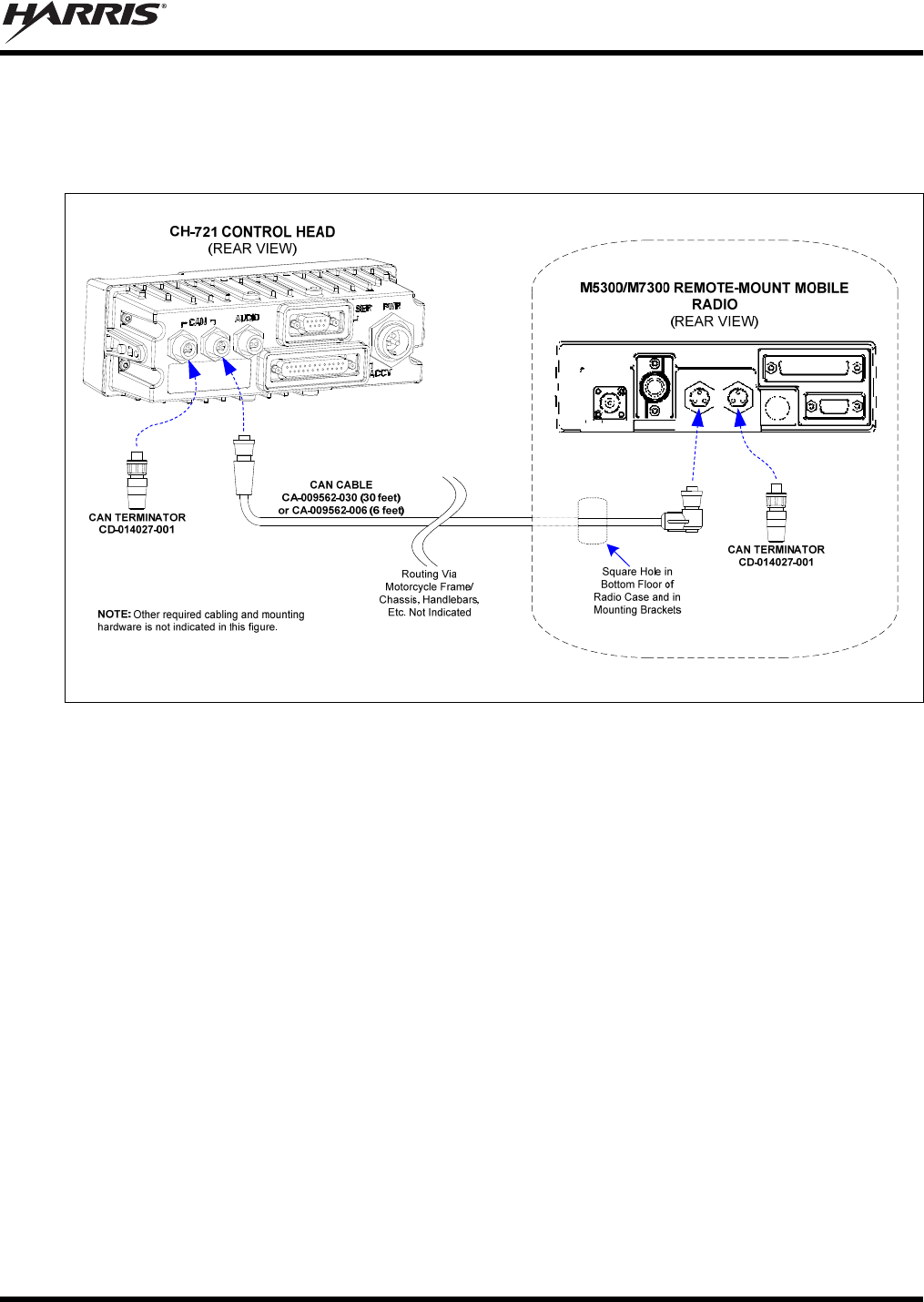
MM-015371-001, Rev. C
53
3. Make a service loop in the cable near the back of the control head.
4. Route the cable from the rear of the control head to the weather-resistant motorcycle radio case. If the
control head is mounted on the motorcycle’s handlebars, leave sufficient slack in the cable to allow
for full handlebar steering/travel without any stretching of the cable. Protect the cable from chafing.
Figure 10-1: CAN Terminators and Control Head-to-Radio CAN Cable Connection
5. Route the CAN cable it into the case by passing it through the square hole in the bottom floor case.
6. Mate this end of the cable to one of the two CAN port connectors on the rear panel of the radio.
7. Mate another CAN terminator to the other CAN port connector on the rear panel of the radio. This
action makes the CAN termination at the radio-end of the CAN link.
8. Loop, tie and stow the excess cable as necessary, leaving a service loop at the back of the radio and at
the back of the control head.
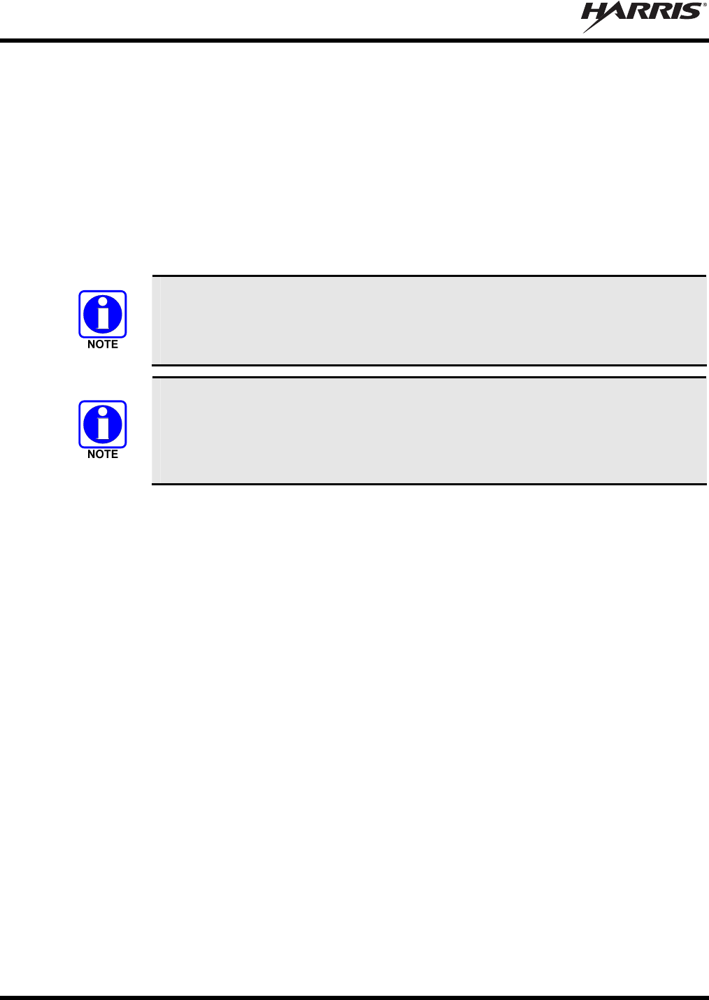
MM-015371-001, Rev. C
54
11 HEADSET/PORTABLE RADIO CONNECTIONS
Several different-type headsets are available for use with a motorcycle-mounted M5300/M7300 mobile
radio. These headsets have helmet-mounted noise-canceling microphones, and either single or dual-
speakers. The headsets can be attached to helmets.
In addition, several different-type helmet headset interface cables are available. These cables include
those with either pushbutton or rocker-type PTT switches, both with and without CG disable switches.
Also, belt-box cable assemblies are available. A belt box allows connection of either a headset or a
portable radio to the mobile radio.
Respective option numbers are listed in Table 4-6 on page 27.
Headset speakers have a nominal impedance of 24 ohms. Using a headset with a
different speaker impedance value will result in non-optimum sound performance from
the speaker(s). The SM-KA-23 dual-speaker helmet kit has its two speakers wired in
parallel. They must be re-wired in series to perform properly.
Headset Helmet Kit Interface Cables SM-MCH-71GT and SM-MCK-71GT each have
a pushbutton switch that only supports the PTT function. However, Headset Helmet
Kit Interface Cables SM-MCH-72GT, SM-MCK-72GT, and SM-MCH-73GT each
have a three-position rocker switch that supports both the PTT and CG decode disable
functions.
11.1 CONNECTING A HEADSET TO THE RADIO (WITHOUT BELT BOX)
To connect a headset to the M5300/M7300 mobile radio (without using a belt box), follow this procedure:
1. Open the motorcycle radio case.
2. As illustrated in Figure 11-1 on page 55, connect the male 44-pin D-subminiature (DB-44) connector
of Headset Adapter Cable CA-012349-002 to the female DB-44 connector on the rear of the radio.
Using a small flat-blade screwdirver, tighten the two (2) jackscrews securely.
3. Mate the male DB-25 connector of Accessory Cable 19B802554P24 to the female DB-25 connector
of the Headset Adapter Cable. Tighten the two (2) jackscrews securely.
4. Route the Accessory Cable’s round 8-pin waterproof connector through the square hole in the bottom
floor of the motorcycle radio case. This cable’s connector must be located near the motorcycle
operator’s/rider’s hip position, typically near the front of the saddle (i.e., motorcycle’s seat). The
connector should remain at least partially exposed so the operator/rider can easily connect to and
disconnect from it as necessary. Tie and stow the cable securely under the saddle.
5. Inside the case, coil-up these two cables and tie and stow them securely. The female DB-25 end of the
Accessory Cable is not normally used in M5300/M7300 mobile radio motorcycle applications.
6. Install the headset into the helmet per instructions provided with the headset.
7. Install the PTT switch of the Headset Helmet Kit Interface Cable (option number SM-MCH-71GT,
etc.) by first mounting the PTT switch to the motorcycle’s handlebar. The PTT switch may or may
not also have a CG disable switch. Typically, the PTT switch is mounted to the left handlebar. Insure
the switch and its cable installation does not obstruct movement of the handlebar or other motorcycle
controls in any way.
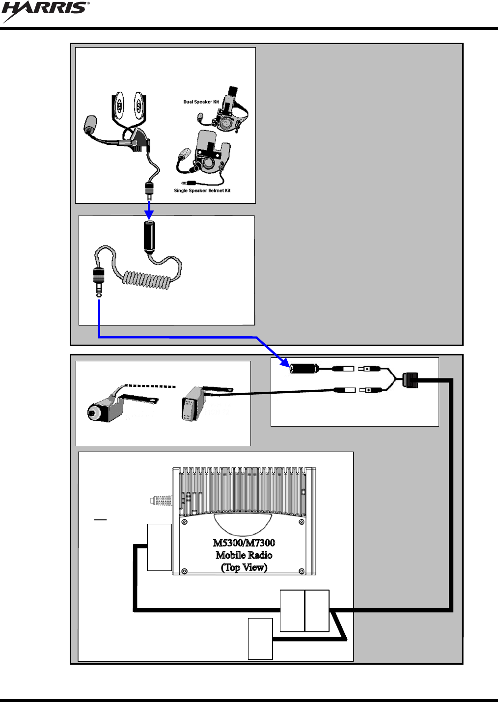
MM-015371-001, Rev. C
55
Helmet Headset
Half-Shell Helmet
SM-KA-11FG,
SM-KA-21FG
3/4-Shell Helmet
SM-KA-13, SM-KA-23
Extender Cable
25-0694
Handlebar PTT Switch
(Depends On Function and Motorcycle)
PTT Only
Pushbutton Switch
PTT + CG Disable
Rocker Switch
MOTORCYCLE
Accessory Cable
19B802554P24
Headset Adapter Cable
CA-012349-002
(No connection required to
this DB-25 connector. Tie
and stow it in radio case.)
4-Conductor
Quick-Disconnect
Jack
4-Conductor
Quick-Disconnect
Plug
Y-Cable
MOTORCYCLE
OPERATOR/RIDER
Motorcycle
Radio Case
waterproof
8-pin round
connector
(P2)
M5300/M7300
Mobile Radio
(Top View)
NOTE: Required
DC power, antenna
and CAN cable
connections are
not indicated.
Motorcycle Harness
(Depends On Motorcycle and PTT Switch)
Male
DB-25
(P1)
Female
DB-25
(J1)
Female
DB-25
(J1)
Male
DB-44
(P1)
Figure 11-1: Headset-to-Mobile Radio Connection
MM-015371-001, Rev. C
56
To enable the PTT switch on the handlebar switch for external headset options, the
mobile radio must be programmed so its INP2 input is defined as “PTT” or
“EXTPTT”. Without this software programming, the radio cannot be keyed via a
headset.
8. Continue installation of the PTT switch by routing its small plug to the location near the round 8-pin
waterproof connector of Accessory Cable 19B802554P24.
9. Connect the Y-cable’s 8-pin connector to the 8-pin connector of Accessory Cable 19B802554P24.
Refer to Figure 11-1 as necessary.
10. Connect the PTT switch to the Y-cable by mating the plug on the end of the switch’s cable to the jack
of the Y-cable.
11. As illustrated in Figure 11-1, use Extender Cable SM-25-0694 (or equivalent) to connector the
headset to the Y-cable.
11.2 CONNECTING A HEADSET/PORTABLE RADIO TO THE MOBILE
RADIO (WITH BELT BOX)
To connect a headset to the M5300/M7300 mobile radio if a belt box is not required, follow this
procedure.
1. Open the motorcycle radio case.
2. As illustrated in Figure 11-2 on page 57, connect the male 44-pin D-subminiature (DB-44) connector
of Headset Adapter Cable CA-012349-002 to the female DB-44 connector on the rear of the radio.
Using a small flat-blade screwdirver, tighten the two (2) jackscrews securely.
3. Mate the male DB-25 connector of Accessory Cable 19B802554P24 to the female DB-25 connector
of the Headset Adapter Cable. Tighten the two (2) jackscrews securely.
4. Route the Accessory Cable’s round 8-pin waterproof connector through the square hole in the bottom
floor of the motorcycle radio case. This cable’s connector must be located near the motorcycle
operator’s/rider’s hip position, typically near the front of the saddle (i.e., motorcycle’s seat). The
connector should remain at least partially exposed so the operator/rider can easily connect to and
disconnect from it as necessary. Tie and stow the cable securely under the saddle.
5. Inside the case, coil-up these two cables and tie and stow them securely. The female DB-25 end of the
Accessory Cable is not normally used in M5300/M7300 mobile radio motorcycle applications.
6. Install the headset into the helmet per instructions provided with the headset.
7. Install the PTT switch of the Headset Helmet Kit Interface Cable (option number SM-MCH-71GT,
etc.) by first mounting the PTT switch to the motorcycle’s handlebar. The PTT switch may or may
not also have a CG disable switch. Typically, the PTT switch is mounted to the left handlebar. Insure
the switch and its cable installation does not obstruct movement of the handlebar or other motorcycle
controls in any way.
To enable the PTT switch on the handlebar switch for external headset options, the
mobile radio must be programmed so its INP2 input is defined as “PTT” or
“EXTPTT”. Without this software programming, the radio cannot be keyed via a
headset.
MM-015371-001, Rev. C
57
Helmet Headset
Half-Shell Helmet
SM-KA-11FG,
SM-KA-21FG
3/4-Shell Helmet
SM-KA-13, SM-KA-23
Portable PTT
Motorcycle / Portable
Selector Switch
Portable Radio
(Portable Cable is Part of
Belt Box Assembly)
Belt Box Assembly
(Typically; Exact Type
Depends On Portable Radio)
4-Conductor
Quick-Disconnect
Plug
MOTORCYCLE
OPERATOR/RIDER
Handlebar PTT Switch
(Depends On Function and Motorcycle)
PTT Only
Pushbutton Switch
PTT + CG Disable
Rocker Switch
MOTORCYCLE
Accessory Cable
19B802554P24
Headset Adapter Cable
CA-012349-002
(No connection required to
this DB-25 connector. Tie
and stow it in radio case.)
Y-Cable
Motorcycle
Radio Case
waterproof
8-pin round
connector
(P2)
M5300/M7300
Mobile Radio
(Top View)
NOTE: Required
DC power, antenna
and CAN cable
connections are
not indicated.
Motorcycle Harness
(Depends On Motorcycle and PTT Switch)
Male
DB-25
(P1)
Female
DB-25
(J1)
Female
DB-25
(J1)
Male
DB-44
(P1)
Figure 11-2: Headset/Portable Radio-to-Mobile Radio Connection

MM-015371-001, Rev. C
58
8. Continue installation of the PTT switch by routing its small plug to the location near the round 8-pin
waterproof connector of Accessory Cable 19B802554P24.
9. Connect the Y-cable’s 8-pin connector to the 8-pin connector of Accessory Cable 19B802554P24.
Refer to Figure 11-2 as necessary.
10. Connect the PTT switch to the Y-cable by mating the plug on the end of the switch’s cable to the jack
of the Y-cable.
11. Route the long end of the Y-cable (with the 4-conductor quick-disconnect jack) to a location near hip-
position of the motorcycle operator, or to another convenient location per request of the motorcycle
operator/customer.
12. As illustrated in Figure 11-2, connect the Belt Box to the Y-cable’s 4-conductor quick-disconnect
jack.
11.3 HEADSET OPERATION
If the motorcycle is equipped with Headset Helmet Kit Interface Cable option SM-MCH-71GT or SM-
MCK-71GT, to transmit, simply press and hold the PTT button on the PTT switch then talk into the
headset’s mic. To receive, stop talking and release the PTT button. When receiving, adjust the volume
control on the control unit for the desired speaker audio level.
If the motorcycle is equipped with Headset Helmet Kit Interface Cable option SM-MCH-72GT, SM-
MCH-73GT or SM-MCK-72GT, to transmit, press and hold the three-position toggle switch to its
momentary (PTT) position and then talk into the headset’s mic. To receive, stop talking and release the
toggle switch so it returns to its center position. In the center position, the radio is in monitor mode
(programmed receive decoder is deactivated). To exit the monitor mode and re-activate the programmed
receive decoder, press the toggle switch to the latched position. When receiving, adjust the volume
control on the control unit for the desired speaker audio level.
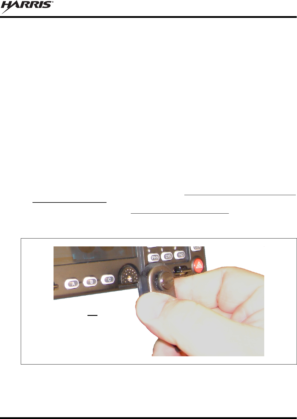
MM-015371-001, Rev. C
59
12 MICROPHONE ATTACHMENT
There are several versions of microphones available for use with the radio. Each has a 17-pin flush-mount
type connector that mates with the mic connector on the front panel of the control head. The mic’s
connector includes a captive thumbscrew that secures it to the mic connector on the front panel of the
control head. A microphone clip is included with each microphone. The radio can be configured to
provide a monitor function when the microphone is cradled in the clip. Connect the mic to the control
head and install the clip as follows:
1. Select a mounting surface location that has clearance for the mic when it is stowed in the clip, and
then attach the microphone clip to the surface. The use of self-locking hardware (i.e., machine screws
with washers and self-locking nuts) is recommended. Tighten securely.
2. Using the microphone clip as a template, drill mounting holes in the surface of the selected location.
3. The microphone clip must be grounded to the vehicle’s chassis. If not mounted to a grounded metal
surface, complete this requirement by adding a jumper wire attached from chassis ground to the clip.
4. As illustrated in Figure 12-1, grasp the mic’s connector with a thumb and index finger on the sides of
the connector just adjacent to the thumbscrew.
5. Position connector just in front of the control head’s mic connector so its male pins can engage
straight into the female (socket) pins of the control head’s mic connector. The thumbscrew must be
oriented directly above the hanging mic cable.
6. Mate the two connectors by pressing them fully together. Do not apply any force to the thumbscrew
when mating the connectors.
7. Tighten the thumbscrew finger-tight. Do not use a screwdriver to tighten it.
8. Clip the microphone to the clip.
Figure 12-1: Attaching the Microphone to the CH-721Control Head
As illustrated, do not apply any
force to the thumbscrew when
mating the mic connectors.
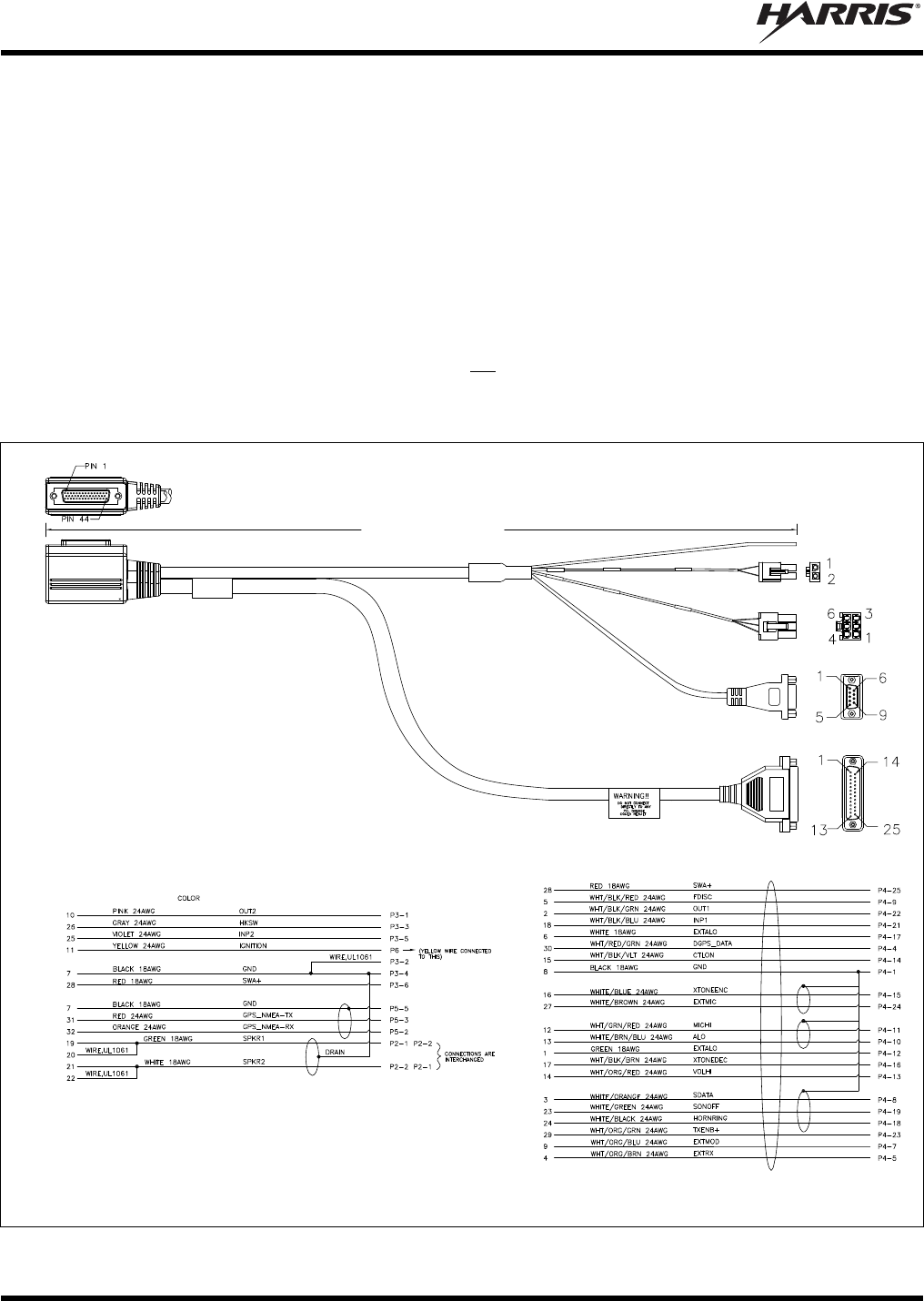
MM-015371-001, Rev. C
60
13 OPTIONAL CABLES
13.1 M5300/M7300 OPTION CABLE CA-012349-001
M5300/M7300 Option Cable CA-012349-001 connects to the 44-pin I/O connector on the rear of the
radio. It breaks out into several smaller standardized connectors, allowing straightforward access to
external I/O interfaces provided by the radio. The cable also shortens radio removal and re-installation
time when required. The cable is shown in Figure 13-1 below, and pin-out details are included in Table
13-1. The cable’s 44-pin D-subminiature connector that mates with the connector on the rear of the radio
is identified P1.
P2, the cable’s 2-pin connector, provides connections for an external speaker in a front-mount
M5300/M7300 mobile radio installation. P2 is not used in motorcycle installations, which employ a
remote-mount M5300/M7300 mobile radio. In this case, the speaker connection is made at the rear of the
CH-721 control head as the audio amplifier in the control head drives the external speaker.
ASSEMBLY DIAGRAM
WIRING DIAGRAM
Approximately 66 inches
(170 centimeters)
P6
P2
P3
P5
P4
P1
(Pin-Out
View)
P1
(Side
View)
P1
P1
(Made From PS-CA-012349 Rev. B)
Figure 13-1: M5300/M7300 Option Cable CA-012349-001
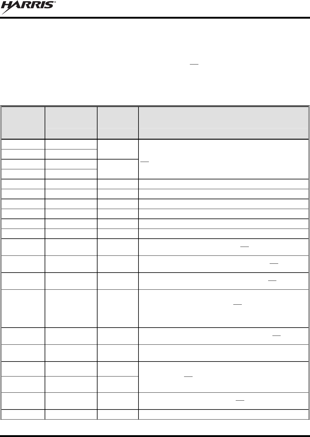
MM-015371-001, Rev. C
61
P3, the cable’s 6-pin connector, is a connector for basics accessories (e.g., hookswitch, etc.).
P4, the cable’s 25-pin D-subminiature (DB-25) connector, provides audio and data connections for
connections to optional equipment.
P5, the cable’s 9-pin D-subminiature (DB-9) connector, is not used in motorcycle applications of the
radio. In standard mobile applications of the radio, this connector provides NMEA-formatted GPS serial
data connections for the external computer processing the NMEA-formatted GPS data received by the
radio’s internal GPS receiver.
Table 13-1: M5300/M7300 Option Cable CA-012349-001 Interconnections
44-PIN I/O
CABLE
CONNECTOR
P1 PIN
SIGNAL NAME TO/FROM DESCRIPTION
19 SPKR1
20 SPKR1
P2 pin 1
21 SPKR2
22 SPKR2
P2 pin 2
Speaker Audio Outputs 1 and 2. These speaker outputs are
not used in a motorcycle installation, since the audio amplifier
in the CH-721 control head drives the external speaker.
10 OUT2 P3 pin 1 Digital Output 2 (open-collector).
7 GND P3 pins 2 & 4 Chassis Ground (fused on radio’s PK Board at 3.15 amps).
26 HKSW P3 pin 3 Hookswitch Digital Input. Active = Ground. Inactive = Open.
25 INP2 P3 pin 5 Digital Input 2.
28 SWA+ P3 pin 6 Switched A+ (DC Power) Output.
8 GND P4 pin 1 Chassis ground (fused on PK Board at 3-amps).
30 DGPS_DATA P4 pin 4 GPS Serial Data. This connection is not used in a motorcycle
installation.
4 EXTRX P4 pin 5 External Rx Audio Output. This connection is not used in a
motorcycle installation.
9 EXTMOD P4 pin 7 External Tx Audio Input. This connection is not used in a
motorcycle installation.
3 SDATA P4 pin 8
In a motorcycle installation (i.e., remote-mount radio), this pin
on the radio’s DB-44 connector is not functional. For siren/PA
interfacing, use the respective pins on the CH-721 Option
Cable’s female DB-25 connector. See Section 13.5 for
additional information.
5 FDISC P4 pin 9 Buffered Discriminator Audio. This connection is not used in a
motorcycle installation.
13 ALO P4 pin 10
A
udio Ground/Reference (fused on radio’s PK Board at
3.15 amps).
12 MICHI P4 pin 11
1 EXTALO P4 pin 12
In a motorcycle installation (i.e., remote-mount radio), this
MICHI input is not functional. For siren/PA interfacing, use
the respective pins on the CH-721 Option Cable’s female
DB-25 connector. See Section 13.5 for additional information.
14 VOLHI P4 pin 13 Volume High. This connection is not used in a motorcycle
installation.
15 CTLON P4 pin 14 Control On Digital Output.
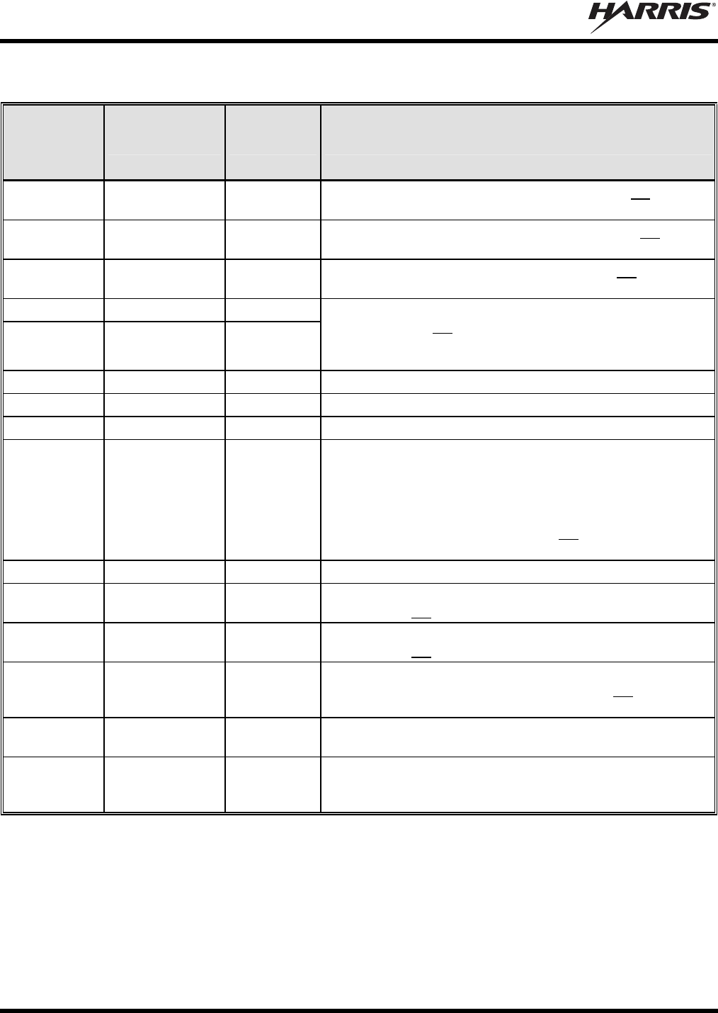
MM-015371-001, Rev. C
62
Table 13-1: M5300/M7300 Option Cable CA-012349-001 Interconnections
44-PIN I/O
CABLE
CONNECTOR
P1 PIN
SIGNAL NAME TO/FROM DESCRIPTION
16 XTONEENC P4 pin 15 External Tone Encode Audio. This connection is not used in a
motorcycle installation.
17 XTONEDEC P4 pin 16 External Tone Decode Audio. This connection is not used in
a motorcycle installation.
6 EXTALO P4 pin 17 External Audio Output. This connection is not used in a
motorcycle installation.
24 HORNRING P4 pin 18
23 SONOFF P4 pin 19
In a motorcycle installation (i.e., remote-mount radio), these
two (2) pins are not functional. For siren/PA interfacing, use
the respective pins on the CH-721 Option Cable’s female
DB-25 connector. See Section 13.5 for additional information.
18 INP1 P4 pin 21 Digital Input 1.
2 OUT1 P4 pin 22 Digital Output 1 (open-collector).
29 TXENB+ P4 pin 23 Transmit Enable B+.
27 EXTMIC P4 pin 24
Pin 27 of the radio’s DB-44 connector is the radio’s External
Mic Audio Input for a headset microphone (or any second mic
audio source such as a boom mic or mic audio from a
portable radio (via a belt box)). For a standard headset
installation, use Headset Adapter Cable CA-012349-002 and
Accessory Cable 19B802554P24, not Option Cable CA-
012349-001. See Section 11 for additional information.
28 SWA+ P4 pin 25 Switched A+ DC Power Output.
32 GPS_NMEA_RX P5 pin 2 Serial Rx Input for GPS NMEA-Formatted Serial Data. This
connection is not used in a motorcycle installation.
31 GPS_NMEA_TX P5 pin 3 Serial Tx Output for GPS NMEA-Formatted Serial Data. This
connection is not used in a motorcycle installation.
7 GND P5 pin 5
Ground for GPS Serial Data Signals (fused on radio’s PK
Board at 3.15 amps). This connection is not used in a
motorcycle installation.
11 IGNITION
(no
connection) Unused/Spare ignition sense input.
33
through
44
— (no
connections) These pins of P1 are not used/not connected.
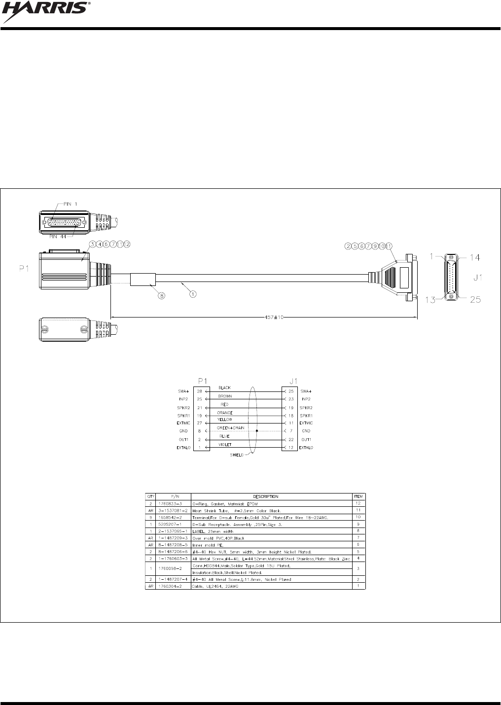
MM-015371-001, Rev. C
63
13.2 HEADSET ADAPTER CABLE CA-012349-002
As described in Section 11 of this manual, Headset Adapter Cable CA-012349-002 is required to connect
a headset or a portable radio (via belt box) to the M5300/M7300 mobile radio. The cable’s assembly
diagram is shown in Figure 13-2 below.
The cable’s male 44-pin D-subminiature (DB-44) connector, identified P1, mates with the female DB-44
connector on the rear of the radio.
The cable’s female DB-25 connector, identified J1, mates to the male DB-25 connector of Accessory
Cable 19B802554P24. Refer to Section 11 for additional information. Accessory Cable 19B802554P24
is illustrated in Section 13.3 that follows.
ASSEMBLY DIAGRAM
WIRING DIAGRAM
PARTS LIST
(Made From PS-CA-012349 Rev. A)
Figure 13-2: Headset Adapter Cable CA-012349-002
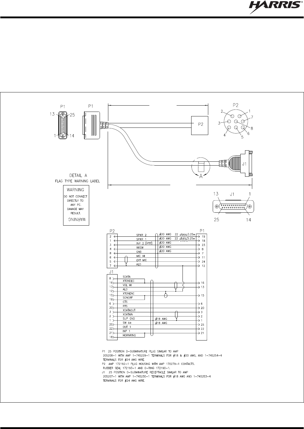
MM-015371-001, Rev. C
64
13.3 ACCESSORY CABLE 19B802554P24
Accessory Cable 19B802554P24 is required when making headset and/or portable radio connections as
described in Section 11 of this manual. As illustrated in Figure 11-1 (page 55) and Figure 11-2 (page 57),
this cable’s male DB-25 connector, identified P1, mates to the female DB-25 connector of Headset
Adapter Cable CA-012349-002. The cable’s round 8-pin waterproof connector, identified P2, mates to
the motorcycle harness Y-cable. In non-M5300/M7300 applications, Accessory Cable 19B802554P24
also supports connections to an external siren and light system via its connector J1.
=
NOTES:
=
=
0.6
m
eters
(23.6 inches)
1.75 meters
(68.9 inches)
(Made From 19B802554 Rev. AD, Sh. 24)
Figure 13-3: Accessory Cable 19B802554P24
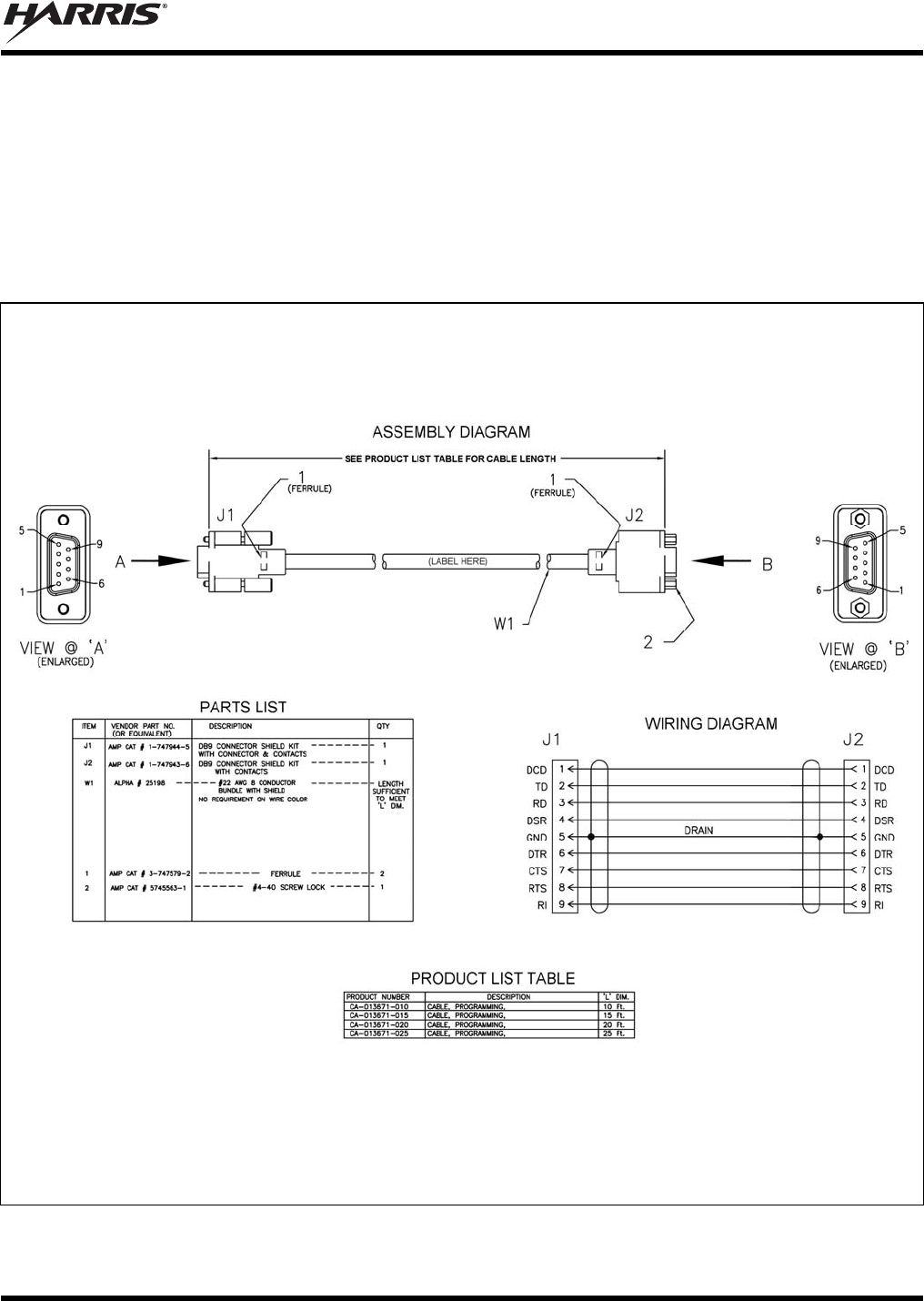
MM-015371-001, Rev. C
65
13.4 SERIAL PROGRAMMING CABLES CA-013671-010 AND -020
Serial Programming Cable CA-013671-010 (10 feet long) and CA-013671-020 (20 feet long) can be used
to program and configure the M5300/M7300 mobile radio via a Personal Computer (PC). This cable has a
female DB-9 connector on one end for connection to the PC’s serial port and a male DB-9 connector on
the other end for connection to the serial port on the rear of the radio. The cable’s assembly and wiring
diagrams are shown in Figure 13-4 below.
If the utilized PC is not equipped with a DB-9 serial port connector, the use of a suitable adapter will be
required, such as USB-to-RS-232 Adapter Cable CN24741-0001.
(Made From PS-CA-013671 Rev. -)
Figure 13-4: Programming Cables CA-013671-010 and CA-013671-020
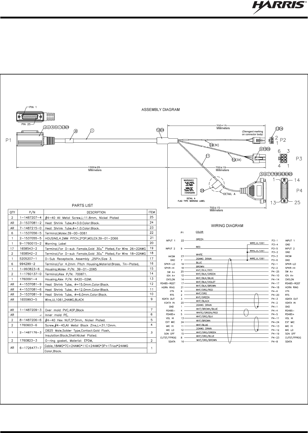
MM-015371-001, Rev. C
66
13.5 CH-721 OPTION CABLE CA-011854-001
CH-721 Option Cable CA-011854-001 can be used to connect optional equipment to the 25-pin
D-subminiature (DB-25) connector on the rear of the CH721. This cable expands the connections
available at the 25-pin connector to three (3) separate connectors. The cable’s assembly and wiring
diagrams are shown in Figure 13-5 below.
(Made From PS-CA-011854 Rev. D)
Figure 13-5: CH-721 Option Cable CA-011854-001
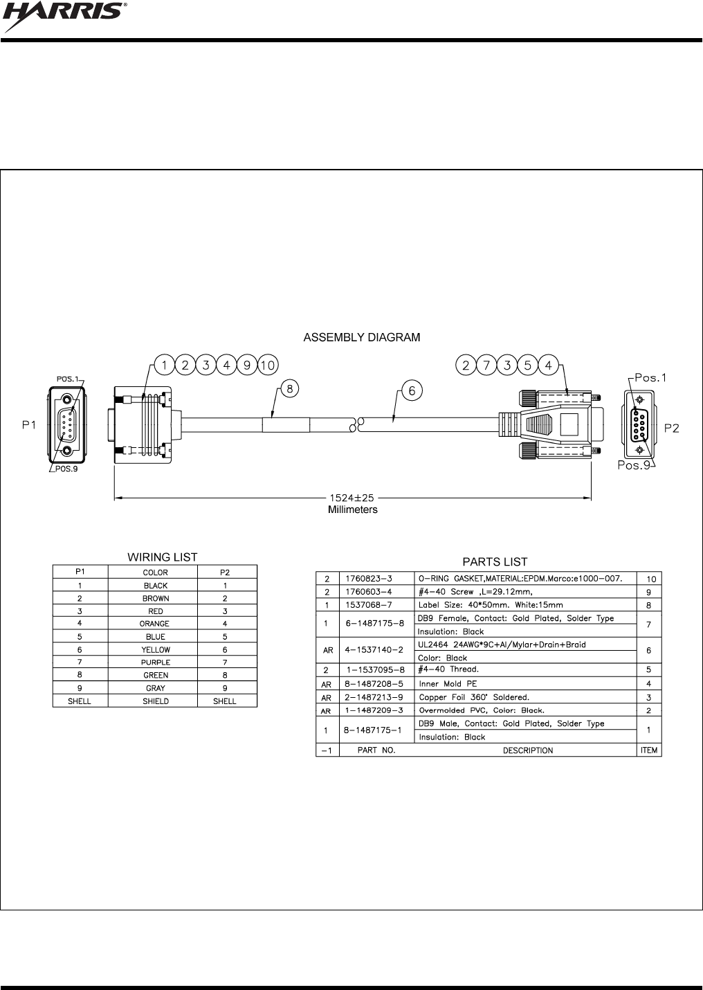
MM-015371-001, Rev. C
67
13.6 CH-721 SERIAL PROGRAMMING CABLE CA-104861
Serial Programming Cable CA-104861 (5 feet) can be used to program and configure the CH-721 control
head via a Personal Computer (PC). This cable has a female DB-9 connector on one end for connection to
the PC’s serial port and a male DB-9 connector on the other end for connection to the serial port on the
rear of the head. The cable’s assembly and wiring diagrams are shown in Figure 13-6 below.
(Made From PS-CA-104861 Rev. A)
Figure 13-6: Programming Cable CA-104861
MM-015371-001, Rev. C
68
14 INITIAL POWER-UP TEST
1. At the radio’s main waterproof (HFB-type) fuse holder installed near the vehicle battery, insert the
15-amp AGC-type fuse that was included with the radio’s DC Power Cable.
2. Tie and stow all fuse holders at this location to prevent excess vibration/movement.
3. Carefully reconnect the vehicle’s battery ground cable.
4. If not already, temporarily connect the mobile antenna cable from the vehicle-mounted mobile
antenna to the female TNC RF connector on the rear panel of the radio. This is a temporary
connection until test procedures in Section 15 are complete.
5. If the installation is wired so the vehicle’s ignition key/switch turns the radio on and off, turn the
switch to the Accessory or Run position.
6. If the control head is not already powered up, do so by rotating its on/off/volume control clockwise
out of the detent position.
7. Verify the control head has powered-up by observing its display. If the display is not lit, refer to
Section 10.1.1 as necessary.
Unlike many mobile radio products, the radio powers-up to the state of last control.
As long as the software configuration parameters have been loaded, successful installation is almost
immediately realized:
After a short boot-up sequence, the control head displays login information and/or a talk group.
If no errors are displayed, the installation is most-likely properly wired.
If an error is displayed, recheck all cable connections, verify all fuses are properly installed, and
verify battery power on the load side of the fuses, etc. If problems persist, contact the Technical
Assistance Center (see page 19).
Consult the Operator’s Manual for operational information.
Refer to the following section for performance test information.
MM-015371-001, Rev. C
69
15 SETTING MAXIMUM TRANSMIT POWER LEVEL AND
ANTENNA PERFORMANCE TESTS
This section includes procedures to set the radio’s maximum transmit output power level and to verify the
performance of the installation’s mobile antenna system. The respective subsections include:
Changing Operating Mode for Tests
Required Test Equipment
Transmit Power Level Adjustments (for all operating modes)
Transmitting into a Dummy Load (a 50-Ohm RF Terminator)
Transmitting into the Mobile Antenna
CAUTION
The accuracy of test results depends upon a DC power source in the range of 13.8 to
16 volts DC, with a current capacity of greater than 8 amps. Make sure the vehicle’s
battery is fully charged by running the engine for a few minutes before the test, and
keep the engine running during the test procedures. Abide by the following
WARNING!
If the vehicle’s engine must remain running, the vehicle location should be well
ventilated so exhaust fumes from the engine do not cause harm!
CAUTION
If a vehicle equipped with this radio requires jump-starting, the radio installation’s
main AGC fuse (15-amp) should be removed from the holder prior to jump-starting.
Doing so will prevent damage to the radio system.
15.1 CHANGING OPERATING MODE FOR TESTS
To complete tests in this section, placing the radio in a conventional mode and using an average-
responding wattmeter to measure RF transmit power is recommended. However, if the radio is not
programmed for conventional mode operations (i.e., OpenSky Trunking Protocol (OTP) is available but
EDACS Conventional P25 (ECP) is not), tests will require a peak-reading RF wattmeter to measure RF
transmit power. To select either conventional or OpenSky mode, use one of the following procedures:
15.1.1 Changing from OpenSky to Conventional
1. If necessary, apply power to the radio and turn it on.
2. Use the control head’s / Ramp Control to scroll through the menu until Mode Menu appears in
the middle line of the display. This control is shown in Figure 8-1 and in Figure 8-2 on page 40.
3. Use the +/- Ramp Control to select an available conventional channel/system.
4. Confirm the selection by pressing the MENU button, then toggling the Ramp Control once (to
select Y for Yes), followed by pressing the MENU button again. The radio will enter the selected
mode as indicated by the display.
5. Select a conventional channel for test transmissions using either the / Ramp Control or the
System/Group/Channel Selection Control (required control per programming).
MM-015371-001, Rev. C
70
15.1.2 Changing from Conventional to OpenSky
1. If necessary, apply power to the radio and turn it on.
2. Use the control head’s / Ramp Control to scroll through the menu until an OpenSky system’s
name is displayed.
3. After a few seconds, the radio will automatically transition to OTP mode for operations on the
selected OpenSky system.
4. If the radio is not programmed for auto-login, login to the OpenSky system. For login instructions,
refer to the respective Operator’s Manual and/or Quick-Guide as necessary. A Quick-Guide is
included with the radio when it ships from the factory. Publication numbers are listed in Section 3.2
(page 18).
5. Select a talk group for test transmissions using either the / Ramp Control or the System/-
Group/Channel Selection Control (required control per programming).
15.2 REQUIRED TEST EQUIPMENT
Table 15-1: Required Test Equipment
TEST EQUIPMENT MODEL / PART NUMBER & DESCRIPTION
Average-Responding
Wattmeter
(for conv. measurements)
Bird Electronic Corp. Model 43 (or equivalent) with Type N female
connectors at input and output ports, and with wattmeter slugs appropriate
for the radio’s transmit RF output power capability and RF band.
Peak-Reading
Wattmeter
(for OpenSky measurements)
Bird Electronic Corp. Model 4314B (or equivalent) with Type N female
connectors at input and output ports.
RF Coaxial
Jumper Cable
Pasternack Enterprises PE3661-(length per CAUTION on page 74)
50-Ohm Coaxial Cable with TNC male connector and Type N male
connector. The utilized cable must have VSWR below 1.5:1 within the RF
passband. Refer to the CAUTION on page 74 for information on the
required length of this cable.
N-to-TNC
RF Adapter
Pasternack Enterprises PE9090 (or equivalent) Type N male to TNC female
adapter. Required to connect the cable of the vehicle-mounted antenna to
the wattmeter.
50-Ohm RF Terminator
(“Dummy Load”)
Pasternack Enterprises PE6106 (or equivalent) 50-ohm RF terminator rated
at greater than 50 watts power, with Type N male connector.
Vehicle-Mounted
Antenna
Tests are performed with the vehicle-mounted antenna per the installation
described in Section 7 of this manual.
Desktop or Laptop
Personal Computer (PC)
With Microsoft Windows operating system and a terminal application to
issue commands through a serial port (such as HyperTerminal). For
EDACS/ProVoice, P25 and conventional operating mode, utilized PC must
have RPM radio programming software installed.
Serial Cable MAMROS0055 (6 feet), or cable CA-013671-010 (10 feet) or CA-013671-
020 (20 feet).
Optional: USB-to-
RS-232 Adapter
Required if the utilized PC is not equipped with a standard DB-9 serial port
connector.
or
MM-015371-001, Rev. C
71
15.3 TRANSMIT POWER LEVEL ADJUSTMENTS
15.3.1 General Information
M5300/M7300 mobile radio factory programming sets maximum transmit RF output power to 35 watts in
EDACS/ProVoice, conventional, and P25 modes, and 19 watts in OpenSky mode.
To meet the minimum safe lateral distances listed in Table 1-1 (page 8), an M5300/M7300 mobile radio
used in a motorcycle application must programmed for a transmit RF output power level that does not
exceed 20 watts. This reduced radio transmit RF output power level also lowers the overall DC load on
the motorcycle’s battery and battery charging system (i.e., alternator). Motorcycles with mobile radios are
typically equipped with additional lights, light flashers, sirens, a PA system, and other electrical
equipment which place additional demand on the motorcycle’s battery and battery charging system.
CAUTION
In a motorcycle application, do not use an M5300/M7300 mobile radio with a transmit
RF output power level exceeding 20 watts. Doing so violates the maximum regulatory
RF power rating specified for this application. In addition, exceeding 20 watts may
result in damage to the motorcycle’s charging system, battery, and other electrical
circuits.
Transmit power level adjustment procedures are presented in the following subsections for all operating
modes. Typically, adjustment (a reduction in transmit RF output power) will be required for
EDACS/ProVoice, conventional, and P25 (ECP) operating modes.
15.3.2 Adjusting Maximum Transmit Output Power for EDACS/ProVoice,
Conventional, and P25 Modes
Adjustment is performed by the Radio Personality Manager (RPM) software application. Follow this
procedure to program each radio system for a 20-watt or less transmit output power level:
1. Connect the radio’s DB-9 serial port connector to a Personal Computer (PC) that has a terminal
application installed, such as Microsoft Windows HyperTerminal. To make this connection, use cable
MAMROS0055 (6 feet), cable CA-013671-010 (10 feet) or cable CA-013671-020 (20 feet). Also, if
the utilized PC is not equipped with a DB-9 serial port connector, the use of a suitable adapter will be
required, such as USB-to-RS-232 Adapter Cable CN24741-0001.
2. Power-up the radio and allow time for it to boot-up.
3. Start-up RPM and read the radio’s personality.
4. Double-click the Systems tab to open the System Setup dialog box. Figure 15-1 shows a typical
dialog box.
5. Each radio system listed in the System Name list has a maximum power level which is set via the
respective Power Level text box. Enter the required maximum power (in watts) on a per-system
basis. Do not enter a setting of more than 20 (for 20 watts).
6. Click on each name in the System Name list as required to verify each radio system in the
personality has a Power Level setting of 20 watts or less.
7. Send the updated personality to the radio.
8. Save the updated personality as necessary.
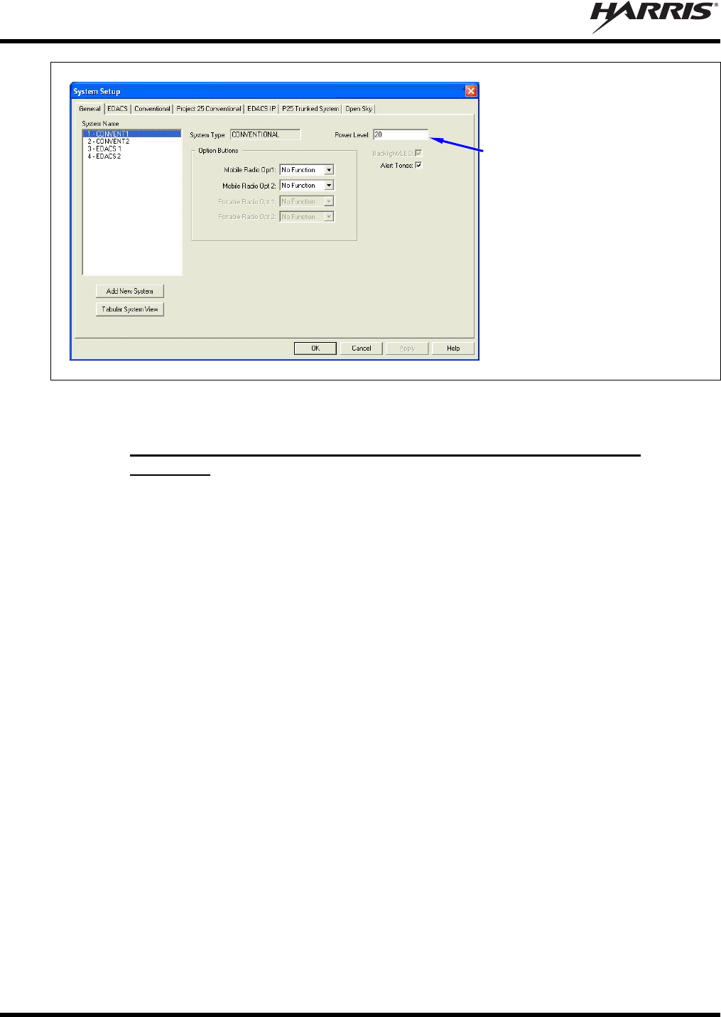
MM-015371-001, Rev. C
72
Figure 15-1: Setting Maximum RF Output Power Level via RPM’s System Setup Dialog Box
15.3.3 Adjusting Maximum Transmit Output Power for OpenSky Mode
(Optional)
If necessary, follow this procedure to adjust the radio’s OpenSky (OTP) mode maximum transmit RF
output power level. A reduction in power level from the factory default setting of 19 watts (earlier radios
were 15 watts) will reduce the load on the motorcycle’s battery and battery charging system (i.e.,
alternator) during radio transmission:
1. Connect the radio’s DB-9 serial port connector to a Personal Computer (PC) that has a terminal
application installed, such as Microsoft Windows HyperTerminal. To make this connection, use cable
MAMROS0055 (6 feet), cable CA-013671-010 (10 feet) or cable CA-013671-020 (20 feet). Also, if
the utilized PC is not equipped with a DB-9 serial port connector, the use of a suitable adapter will be
required, such as USB-to-RS-232 Adapter Cable CN24741-0001.
2. Start-up the PC and configure the terminal application to use the respective serial communication port
(e.g., COM1) with the following settings: terminal emulation = VT100, data rate = 19,200 bps,
number of data bits = 8, number of stop bits = 1, no parity, and no flow control.
3. Power-up the radio and allow time for it to boot-up.
4. Verify the radio is operating in OpenSky mode. If not, refer to Section 15.1.2 on page 70 as required,
and make the change to this mode.
5. Send these two 3-character strings to the radio to initialize its serial port for OTP commands:
+++ (hold down the <Shift> key and press the + key three times)
*** (hold down the <Shift> key and press the * key three times)
On a per-system basis, set
the maximum transmit output
power level (in Watts) via the
respective Power Level text
box.
MM-015371-001, Rev. C
73
6. Send the following command to the radio via the terminal application:
at***** <maximum transmit power> where <maximum transmit power> equals the required
maximum transmit RF output power level in dBm. A space is required after at*****.
For example, to set the maximum power to 10 watts (40 dBm), send at***** 40 to the radio.
Use the following formula to convert watts to dBm: dBm = 10 x Log10(milliwatts), where
1 watt = 1000 milliwatts (1 milliwatt = 0 dBm).
7. Send the following command to the radio so it will reboot and the new power setting will take effect:
atz
8. Disconnect the programming equipment and continue with the test procedure presented in the next
section.
15.4 TRANSMITTING INTO A DUMMY LOAD
1. Using the Type N male to TNC male RF coaxial jumper cable, connect the radio’s antenna connector
to the wattmeter’s input connector. Refer to Figure 15-2 as necessary.
2. Connect the 50-ohm dummy load to the wattmeter’s output connector, in place of the antenna cable
from the mounted mobile antenna.
As previously stated, if conventional mode is not available per radio programming
(i.e., OTP mode is available but ECP mode is not), a peak-reading RF wattmeter is
required to measure RF transmit power. Otherwise, the use of an average-responding
wattmeter is recommended. Recommended wattmeter types are listed in Table 15-1.
3. If not already, turn the radio on and set it to the required operating mode (based upon available radio
programming and test equipment). Refer to Section 15.1 as necessary.
4. Set the radio to a test talk group or conventional channel, if available.
It is recommended that a test talk group/channel be allocated for this testing. This
same group should be used during the antenna test procedure which is presented in the
subsequent section.
5. Position the wattmeter’s slug to measure forward RF output power. Rotate it if necessary. The arrow
on the face of the slug must point away from the radio and towards the dummy load for forward
power measurements.
6. For conventional mode transmissions, set the wattmeter to measure average RF power.
For OpenSky mode transmissions, set the wattmeter to measure peak RF power.
7. Key the radio’s transmitter via the microphone’s PTT button.
8. Verify the measured forward RF output power into the dummy load is within 20% of the maximum
transmit output power (in watts) programming performed per Section 15.3.
Transmit only for as long as needed to take the measurement, then immediately
disable the transmission.
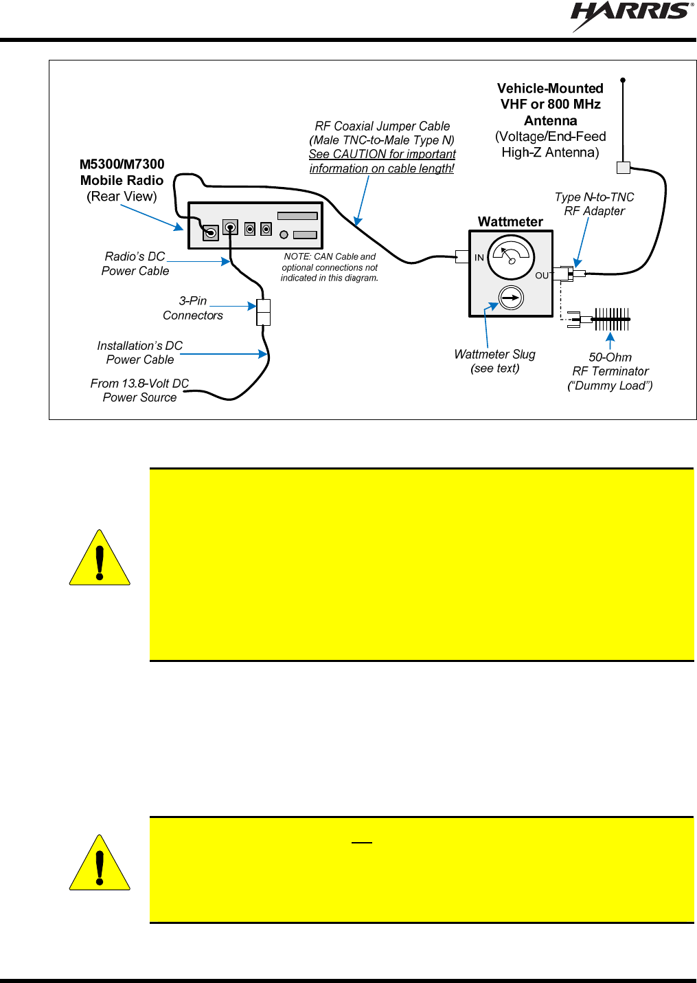
MM-015371-001, Rev. C
74
Figure 15-2: Wattmeter Connections for Antenna System Tests
CAUTION
For accurate RF power measurements when transmitting into the antenna, the length of
the RF coaxial jumper cable plus the length of the directional coupler within the
wattmeter is critical. The summed length of the coaxial jumper cable and the
directional coupler must equal a multiple of a ½-wavelength at the test frequency, with
velocity factors included in length calculations. When making length calculations, use
a velocity factor of 66% for cable with solid polyethylene dielectric/insulation (such as
RG-58C/U or RG-8/U), or use a velocity factor of 79% for cable with foam
polyethylene dielectric/insulation (such as RG-233 or H155). For the wattmeter’s
directional coupler, use a velocity factor of 95%, if it is not otherwise specified by the
wattmeter manufacturer.
9. If the wattmeter reading is within the range, record the measured value in the appropriate space on
the data collection form near the end of this manual.
If the wattmeter reading is outside the range, verify the radio’s power supply voltage (i.e., battery
voltage) is within the specified range, recheck all connections and measure the RF output power
again. If this fails to produce a reading within the range, replace the radio (reprogramming as
required), and repeat this procedure. If problems persist, contact the Technical Assistance Center (see
page 19).
CAUTION
In a motorcycle application, do not use an M5300/M7300 mobile radio with a transmit
RF output power level exceeding 20 watts. Doing so violates the maximum regulatory
RF power rating specified for this application. In addition, exceeding 20 watts may
result in damage to the motorcycle’s charging system, battery, and other electrical
circuits.
MM-015371-001, Rev. C
75
15.5 TRANSMITTING INTO THE MOBILE ANTENNA
1. Connect the antenna cable from the vehicle-mounted antenna to the wattmeter as shown in Figure
15-2.
2. If not already, turn the radio on and set it to the required operating mode (based upon available radio
programming and test equipment). Refer to Section 15.1 as necessary.
3. Set the radio to a test talk group or conventional channel, if available.
It is recommended that a test talk group/channel be allocated for this testing.
Otherwise, interference with other radio users in the system may occur. Also, during
transmissions, always observe the RF exposure-related safety information
presented in Section 1.2 (begins on page 6).
4. Position the wattmeter’s slug to measure forward RF output power. Rotate it if necessary. The arrow
on the face of the slug must point away from the radio and towards the antenna for forward power
measurements.
5. For conventional mode transmissions, set the wattmeter to measure average RF power.
For OpenSky mode transmissions, set the wattmeter to measure peak RF power.
6. Key the radio’s transmitter via the microphone’s PTT button.
7. Verify the measured forward RF output power into the antenna is within 20% of the maximum
transmit output power (in watts) programming performed per Section 15.3.
Transmit only for as long as needed to take the measurement, then immediately
disable the transmission.
8. If the wattmeter reading is within the range, record the value in the appropriate space on the data
collection form near the end of this manual.
If the wattmeter reading is outside the range, verify the radio’s power supply voltage (i.e., battery
voltage) is within the specified range, recheck all connections, and measure the forward power again.
If these checks/corrections fail to produce a reading within the range, check all cabling and
connections and repeat the testing procedure to this point. In the event the wattmeter reading still falls
outside the range, replace the antenna, make sure all connections are seated firmly, and repeat the
testing procedure. If problems persist, contact the Technical Assistance Center (see page 19).
9. Position the wattmeter’s slug to measure reverse (reflected) RF power from the antenna. The arrow
on the face of the slug must point away from the antenna and to the radio to measure reverse power.
10. Key the radio’s transmitter via the microphone’s PTT button.
11. Verify the wattmeter indicates 2 watts or less.
Transmit only for as long as needed to take the measurement, then immediately disable
the transmission.
MM-015371-001, Rev. C
76
12. If the wattmeter reading is within the range, record the value in the appropriate space on the data
collection form near the end of this manual.
If the wattmeter reading is outside the range, make sure the antenna is consistent with the specified
frequency range of the radio. Recheck all antenna connections, and measure the reverse power again.
If these checks/corrections fail to produce a reading within the range, replace the antenna and repeat
the entire antenna test procedure. Any value exceeding the maximum allowable reflected power value
will result in a diminished RF output signal. If problems persist, contact the Technical Assistance
Center (see page 19).
13. Disconnect the coaxial cable jumper and wattmeter.
14. Permanently connect the cable from the vehicle-mounted antenna to the radio’s antenna cable by
mating the two TNC connectors together. Use two pairs of soft-jaw pliers to gently tighten this
connection. Do not over-tighten and do not twist either cable.
15. Make several test calls to verify operation of the mobile radio. Before making each call, select talk
group(s) or conventional channel(s) designated for making radio test calls on the respective radio
system.
To prevent RF leakage and ensure peak performance, make sure the antenna cable’s
RF connector at the rear of the radio is tight. Do not over-tighten it, since this may
cause connector damage.
Improper installation of the RF cables may lead not only to poor radio
performance, but also to harmful exposure to RF electromagnetic energy.
Testing is complete. The radio is now ready for normal communications.
MM-015371-001, Rev. C
77
15.6 TEST PERFORMANCE DATA FORM
Enter the information requested on this data collection form. Clip this form and file it as a permanent record of
the tested performance of the M5300/M7300 mobile radio installation.
Clip
Here
Company Performing Installation Technician Performing Test
Date of Test
(mm/dd/yyyy)
Mobile Radio Serial Number Antenna Make and Model Numbers
Power into a Dummy
Load
Watts
Forward Power with
Antenna Reflected Power
with Antenna
Watts
Watts

MM-015371-001, Rev. C
78
16 COMPLETE THE INSTALLATION
Double-check the following items before considering the installation completed:
Verify all newly installed mechanical hardware is mounted securely and all respective mounting
hardware is tight.
Verify all electrical interconnections are connected properly and the associated connector attachment
hardware is tight. Pay special attention to all RF antenna cables!
Verify all related fuses are correctly installed and properly rated.
Verify all electrical cables and wiring are tied, stowed, and protected so they are out of the way of
casual contact, away from sources of extreme heat, and wire chafing cannot occur. Pay special
attention to all RF antenna cables!
To prevent fumes from entering the vehicle’s passenger compartment, seal the hole/grommet/wire
combination at the firewall with a silicon-based sealer.
Verify all vehicle components are properly reinstalled such as kick panels, headliners, and seats.
If the installation includes a separately-mounted on/off power switch for manually turning the radio
(and possibly others systems) on and off, verify it is labelled accordingly. For example: “Radio
ON/OFF.”
Remove all tools and unused hardware from the vehicle.
Verify the test performance data has been recorded on the data collection form shown in this manual.

MM-015371-001, Rev. C
79
17 WARRANTY
A. Harris Corporation, a Delaware Corporation, through its Public Safety and Professional
Communications (PS&PC) Division (hereinafter "Seller") warrants to the original purchaser for use
(hereinafter "Buyer") that Equipment manufactured by or for the Seller shall be free from defects in
material and workmanship, and shall conform to its published specifications. With respect to all non-
Seller Equipment, Seller gives no warranty, and only the warranty, if any, given by the manufacturer
shall apply. Rechargeable batteries are excluded from this warranty but are warranted under a
separate Rechargeable Battery Warranty (ECR-7048).
B. Seller’s obligations set forth in Paragraph C below shall apply only to failures to meet the above
warranties occurring within the following periods of time from date of sale to the Buyer and are
conditioned on Buyer’s giving written notice to Seller within thirty (30) days of such occurrence:
1. for fuses and non-rechargeable batteries, operable on arrival only.
2. for parts and accessories (except as noted in B.1) sold by Seller’s Service Parts Operation, ninety
(90) days.
3. for P7200, P7100IP, P5400, P5300, P5200, P5100, P3300, PANTHER 405P and 605P, M7300,
M7200 (including V-TAC), M7100IP, M5300 and M3300 radios, two (2) years, effective
10/01/2007.
4. for all other equipment of Seller’s manufacture, one (1) year.
C. If any Equipment fails to meet the foregoing warranties, Seller shall correct the failure at its option (i)
by repairing any defective or damaged part or parts thereof, (ii) by making available at Seller’s factory
any necessary repaired or replacement parts, or (iii) by replacing the failed Equipment with equivalent
new or refurbished Equipment. Any repaired or replacement part furnished hereunder shall be
warranted for the remainder of the warranty period of the Equipment in which it is installed. Where
such failure cannot be corrected by Seller’s reasonable efforts, the parties will negotiate an equitable
adjustment in price. Labor to perform warranty service will be provided at no charge during the
warranty period only for the Equipment covered under Paragraph B.3 and B.4. To be eligible for no-
charge labor, service must be performed at Seller’s factory, by an Authorized Service Center (ASC)
or other Servicer approved for these purposes either at its place of business during normal business
hours, for mobile or personal equipment, or at the Buyer’s location, for fixed location equipment.
Service on fixed location equipment more than thirty (30) miles from the Service Center or other
approved Servicer’s place of business will include a charge for transportation.
D. Seller’s obligations under Paragraph C shall not apply to any Equipment, or part thereof, which (i) has
been modified or otherwise altered other than pursuant to Seller’s written instructions or written
approval or, (ii) is normally consumed in operation or, (iii) has a normal life inherently shorter than the
warranty periods specified in Paragraph B, or (iv) is not properly stored, installed, used, maintained or
repaired, or, (v) has been subjected to any other kind of misuse or detrimental exposure, or has been
involved in an accident.
E. The preceding paragraphs set forth the exclusive remedies for claims based upon defects in or
nonconformity of the Equipment, whether the claim is in contract, warranty, tort (including
negligence), strict liability or otherwise, and however instituted. Upon the expiration of the warranty
period, all such liability shall terminate. The foregoing warranties are exclusive and in lieu of all other
warranties, whether oral, written, expressed, implied or statutory. NO IMPLIED OR STATUTORY
WARRANTIES OF MERCHANTABILITY OR FITNESS FOR PARTICULAR PURPOSE SHALL
APPLY. IN NO EVENT SHALL THE SELLER BE LIABLE FOR ANY INCIDENTAL,
CONSEQUENTIAL, SPECIAL, INDIRECT OR EXEMPLARY DAMAGES.
This warranty applies only within the United States.
Harris Corporation
PS&PC Division
221 Jefferson Ridge Parkway
Lynchburg, VA 24501
1-800-528-7711
ECR-7047G

Public Safety and Professional Communications | www.harrispublicsafety.com
221 Jefferson Ridge Parkway | Lynchburg, VA USA 24501 | 1-800-528-7711