HARRIS TR-0057-E Base station transceiver (700 MHz band) User Manual User Guide
HARRIS CORPORATION Base station transceiver (700 MHz band) User Guide
HARRIS >
Contents
- 1. Overview Manual
- 2. User Guide
User Guide

MANUAL P/N 900000034 REV B
1
User Guide
Frequency Standard QFS-106
Model QFS-106
P/N 0150060XX
Revision B
August 2005
Brandywine Communications
2230 South Fairview Street
Santa Ana, CA 92704
(714) 755 1050
(714) 755 0175
http://www.brandywinecomm.com
FCC PART 15, CLASS A VERIFICATION
DOC. # FCC15AVER-B-7-01 REV. E 01/26/00
INFORMATION TO THE USER FOR CLASS A DIGITAL DEVICE
WARNING: This equipment has been tested and
found to comply with the limits for Class A digital
device pursuant to Part 15 of the FCC Rules.
These limits are designed to provide reasonable
protection against harmful interference when the
equipment is operated in a commercial environment.
This equipment generates, uses, and can radiate radio
frequency energy and, if not installed and used in
accordance with the instruction's manual, may cause
interference to radio communications. Operation of
this equipment in a residential area is likely to cause
interference in which case the user will be required to
correct the interference at his own expense.
The user is cautioned that changes and modifications
made to the equipment without approval of the
manufacturer could void the user's authority to operate
this equipment.

MANUAL P/N 900000034 REV B
3
Revision History
REVISION DATE COMMENTS
NC 10-26-04 Original release of QFS-106 user guide.
A 12-14-04 Revision of the rear panel and mechanical outline drawings.
B 08-03-05 Revision of Section 3.1.

MANUAL P/N 900000034 REV B
4
Table of Contents
1 Overview ................................................................................................................................. 5
1.1 Part Number Reference ................................................................................................. 5
2 Specifications.......................................................................................................................... 6
2.1 I/O and Environmental (Rear Panel).............................................................................. 6
2.2 Switch and Indicator (Front Panel)................................................................................. 7
3 Unpacking and Installation......................................................................................................8
3.1 Unpacking ...................................................................................................................... 8
3.2 Installation ...................................................................................................................... 8
3.3 Connections ................................................................................................................... 8
4 Operation .............................................................................................................................. 10
4.1 Powering the QFS-106................................................................................................. 10
4.2 Loss of Input Signal...................................................................................................... 10
4.3 Loss of Output Signal................................................................................................... 10
5 Calibration............................................................................................................................. 11
6 Diagrams............................................................................................................................... 12

MANUAL P/N 900000034 REV B
5
1 Overview
The Brandywine Communications QFS-106 is a high performance reference
frequency standard distribution amplifier. The QFS-106 has two internal
reference oscillator options. The QFS-106 may use either a free running Oven
Controlled Crystal Oscillator (OCXO) or a free running Rubidium Oscillator. Also,
the QFS-106 has various power supply options. The QFS-106 may use either
AC or DC input power supplies. The QFS-106 provides six output channels of a
single reference frequency, typically 10 MHz. The QFS-106 has six individually
buffered low phase noise outputs. When more outputs are required, multiple
QFS-106 units may be daisy-chained to a single reference.
1.1 Part Number Reference
PART NUMBER OSCILLATOR POWER SUPPLY
015006001 OCXO 115/230 VAC
015006002 OCXO 09 – 18 VDC
015006003 OCXO 18 – 36 VDC
015006004 OCXO 36 – 72 VDC
015006011 Rubidium 115/230 VAC
015006012 Rubidium 09 – 18 VDC
015006013 Rubidium 18 – 36 VDC
015006014 Rubidium 36 – 72 VDC

MANUAL P/N 900000034 REV B
6
2 Specifications
2.1 I/O and Environmental (Rear Panel)
SPECIFICATION DESCRIPTION
OCXO Stability 1 x 10
-8
at -30° to -60°C
OCXO Aging 5 x 10
-8
per year
Rubidium Stability ±1 x 10
-10
at 0 to 50°C
Internal Reference
Oscillator
Rubidium Aging 5 x 10
-11
per month
Label J8
Number of Reference Inputs 1 Input
Frequency 10 MHz Standard
Level 1 Vrms into 50 ohm
Reference Input
Connector BNC
Label J7
Number of Reference Outputs 1 Output
Frequency 10 MHz Standard
Level 1 Vrms into 50 ohm
Distortion < 33 dBc
Reference Output
(Buffered from
Reference Input)
Connector BNC
Label Output 1 (J1), Output 2 (J2),
Output 3 (J3), Output 4 (J4),
Output 5 (J5), and Output 6
(J6)
Number of Frequency Outputs 6 Buffered Outputs
Frequency 10 MHz Standard
Level 1 Vrms into 50 ohm
Distortion < 33 dBc
Outputs
Connector BNC
1 Hz -90 dBc/Hz
10 Hz -110 dBc/Hz
100 Hz -140 dBc/Hz
1000 Hz -150 dBc/Hz
Phase Noise at 10
MHz
10000 Hz -157 dBc/Hz
Temperature -30 to +60°C
Environmental
Humidity 95% non-condensing
VDC Model 12 VDC and 4A Fuse VAC Model 115/230 VAC and 250mA
09 – 18 VDC
18 – 36 VDC
VDC Power Supply
36 – 72 VDC
Power
VAC Power Supply 115/230 VAC
VDC Connector DC Connector
Pin A -> Positive VDC Connector 2 Pin Pin B -> Negative
Power Connection
VAC Connector AC Connector
Length (Rack Mount & Chassis) 19.00” and 17.00”
Height 1.720”
Dimension
Width 6.150”
Weight Weight Typically 3 lbs

MANUAL P/N 900000034 REV B
7
2.2 Switch and Indicator (Front Panel)
SWITCH/INDICATOR COLOR DESCRIPTION
POWER SWITCH –– Used to switch the unit on and off
POWER LED GREEN Indicates that the unit has primary power
OUTPUT MONITOR 1 LED GREEN Indicates that Output 1 is present
OUTPUT MONITOR 2 LED GREEN Indicates that Output 2 is present
OUTPUT MONITOR 3 LED GREEN Indicates that Output 3 is present
OUTPUT MONITOR 4 LED GREEN Indicates that Output 4 is present
OUTPUT MONITOR 5 LED GREEN Indicates that Output 5 is present
OUTPUT MONITOR 6 LED GREEN Indicates that Output 6 is present
RED Indicates that the unit is in power up mode or not
locked to the reference input
PLL LED
GREEN Indicates that the unit is phased locked to the
reference input
RB LOCKED LED GREEN Indicates that the rubidium oscillator has reached
resonance lock if installed
CALIBRATE (POTENTIOMETER) –– Used to calibrate the oscillator

MANUAL P/N 900000034 REV B
8
3 Unpacking and Installation
3.1 Unpacking
Carefully remove the QFS-106 from the shipping carton. The following items
should be included in the shipment:
• 1 QFS-106
• 1 user guide
• 1 power cord
• 1 power mating connector (DC voltage only)
Note the power connection on the rear of the QFS-106 chassis. Please take
note of the voltage displayed near this power connection.
If the AC or DC voltage setting is incorrect, use a small screw driver to remove
the fuse holder. Reverse the fuse holder and re-insert the fuse holder, making
sure that the correct AC or DC voltage is now displayed on the rear panel of the
QFS-106.
Use the supplied power mating connector for the QFS-106 unit (DC voltage
only). The user must connect the wires to the connector as shown in the table
below.
DC MODEL DESCRIPTION
Pin A Positive input voltage
Pin B Negative input voltage
Mating Connector Amphenol 97-3106A-10SL-4S
Strain Relief Amphenol 97-3057-1004-1
3.2 Installation
The QFS-106 may be bolted directly onto a 19” rack mount enclosure.
3.3 Connections
Connect the power source to the QFS-106. Now connect the input reference
signal and output reference signals to the appropriate connectors on the rear
panel of the QFS-106. The Reference Output connector may be used when
daisy-chaining multiple QFS-106 units.
MANUAL P/N 900000034 REV B
9
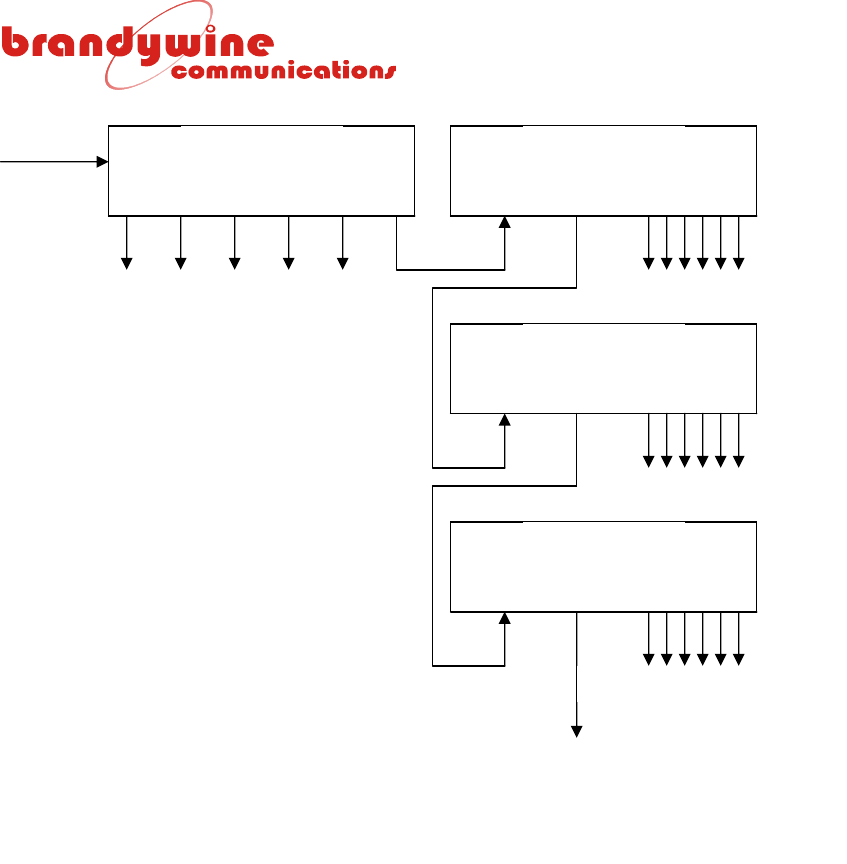
When daisy-chaining multiple QFS-106 units, these units should be connected as
shown in Figure 1. This configuration ensures that all outputs are accurately
locked to a common reference with minimal injection of the phase lock loop
noise.
Power QFS-106 QFS-106
1 2 3 4 5 6 REF IN REF OUT 1 2 3 4 5 6
QFS-106
REF IN REF OUT 1 2 3 4 5 6
QFS-106
REF IN REF OUT 1 2 3 4 5 6
Additional QFS-106
Units
User’s Equipment User’s E
q
ui
p
ment
User’s E
q
ui
p
ment
User’s E
q
ui
p
ment
Figure 1 Daisy-Chain Interconnection

MANUAL P/N 900000034 REV B
10
4 Operation
4.1 Powering the QFS-106
Once all the connections to the QFS-106 have been made, apply power to the
unit by switching the power switch to the on position. The power switch is
located on the rear panel of the unit. The Power LED and Output Monitor LEDs
(1 – 6) on the front panel of the unit will illuminate green.
Please note that units fitted with the quartz oscillators will take approximately five
minutes to warm up and these units will reach full accuracy after twenty-four
hours. Units fitted with the rubidium oscillators will take approximately ten
minutes to warm up.
4.2 Loss of Input Signal
The PLL LED illuminates green when an input signal is present on the Reference
Input connector on the rear panel of the unit. If the reference input fails, the front
panel PLL LED will extinguish.
4.3 Loss of Output Signal
The Output Monitor LEDs (1 – 6) illuminate green when output signals are
present on the Outputs connectors on the rear panel of the unit. If one or more
outputs fail, the front panel Output Monitor LEDs (1 – 6) will extinguish.
Please note that a short circuit on the output cable may not always trigger the
output alarm.

MANUAL P/N 900000034 REV B
11
5 Calibration
The QFS-106 is a free running standard that requires periodic recalibration. The
unit must be calibrated against a frequency standard that is at least ten times
more accurate than the oscillator fitted in the QFS-106 unit. Therefore OCXO
oscillator units must be calibrated against a rubidium reference. Rubidium
oscillator units must be calibrated against a cesium frequency standard or GPS
disciplined rubidium. The front panel mounted potentiometer is used to adjust
the frequency of the QFS-106 unit. The table below describes this calibration.
OUTPUT POTENTIOMETER OUTPUT LEVEL ADJUSTMENT
Calibrate 20 turn potentiometer (front panel) Frequency standard calibration
Output 1 10 turn potentiometer (rear panel) 7 – 13 dBm
Output 2 10 turn potentiometer (rear panel) 7 – 13 dBm
Output 3 10 turn potentiometer (rear panel) 7 – 13 dBm
Output 4 10 turn potentiometer (rear panel) 7 – 13 dBm
Output 5 10 turn potentiometer (rear panel) 7 – 13 dBm
Output 6 10 turn potentiometer (rear panel) 7 – 13 dBm

MANUAL P/N 900000034 REV B
12
6 Diagrams
FIGURE DESCRIPTION
1 QFS-106 Front Panel (AC and DC Models)
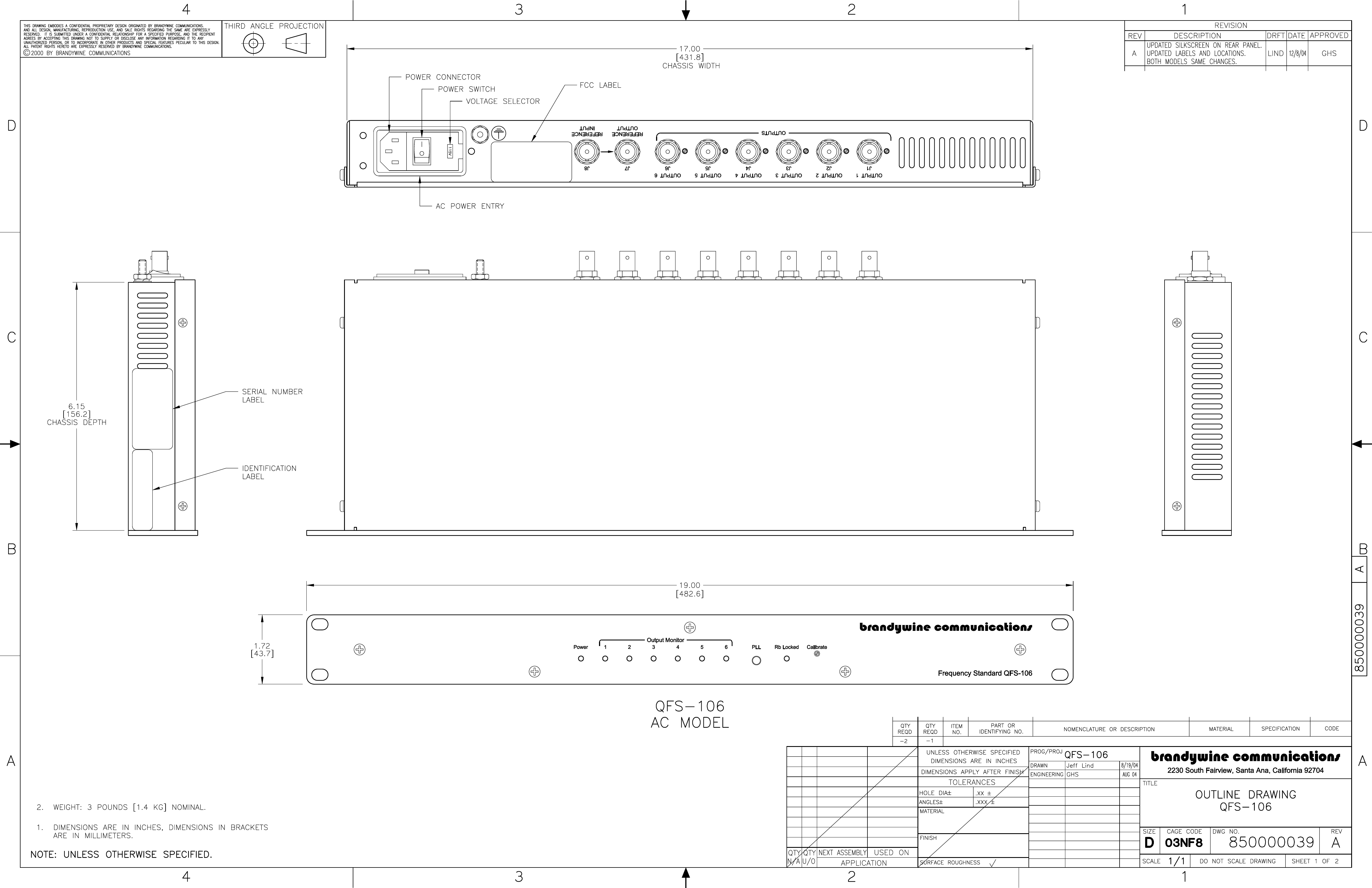
2 QFS-106 Rear Panel (AC Model)
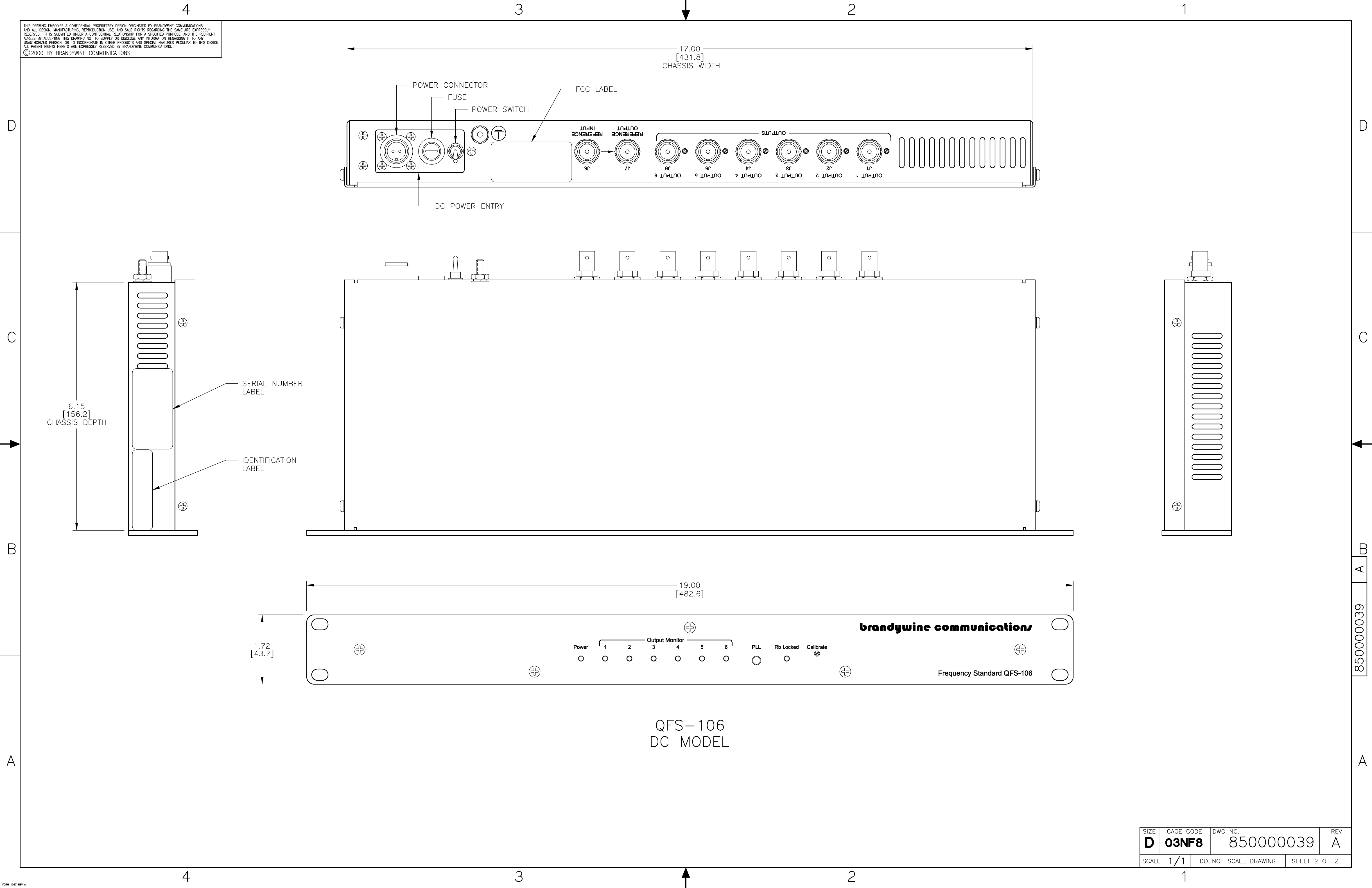
3 QFS-106 Rear Panel (DC Model)
4 QFS-106 Mechanical Outline (AC Model)
5 QFS-106 Mechanical Outline (DC Model)