HARRIS TR-0059-E XG-75 VHF User Manual Manual 1
HARRIS CORPORATION XG-75 VHF Manual 1
UserManual.wiki
>
HARRIS
>
TR-0059-E User Manual
>
Manual 1
Contents
1.
Manual 1
2.
Manual 2
Manual 1
Navigation menu
Upload a User Manual
Namespaces
Wiki Guide
HTML
PDF
Info
Views
User Manual
Discussion / Help
Navigation
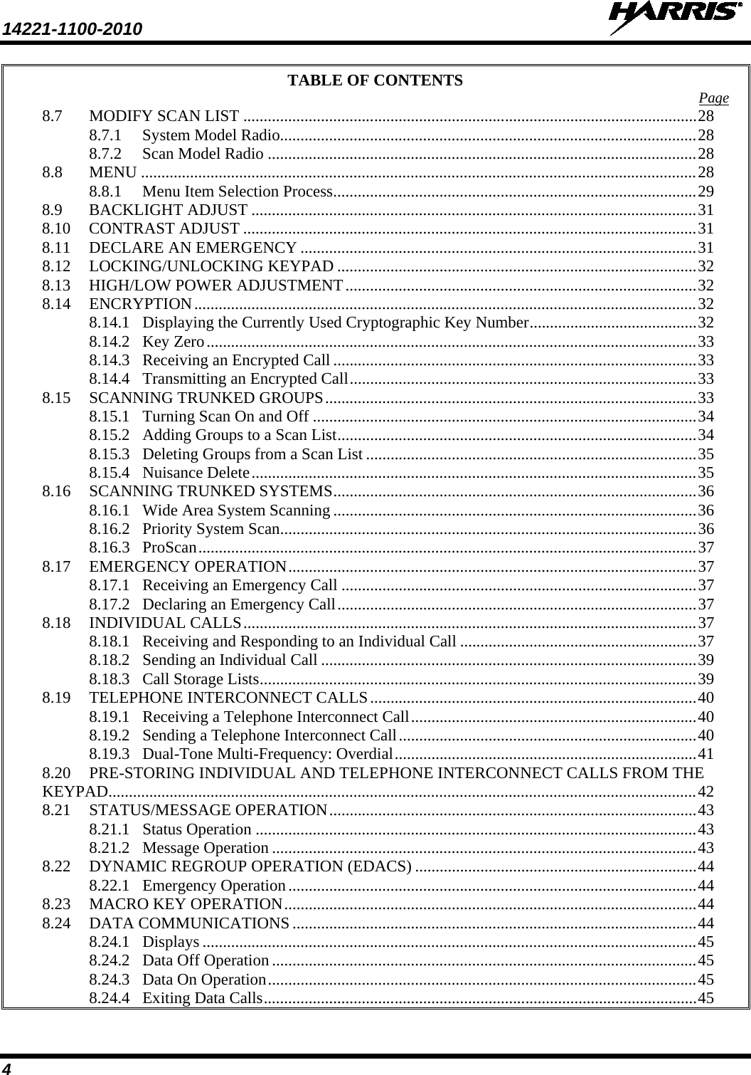
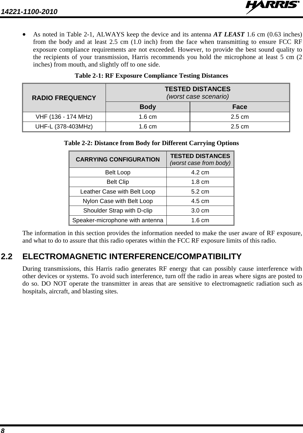
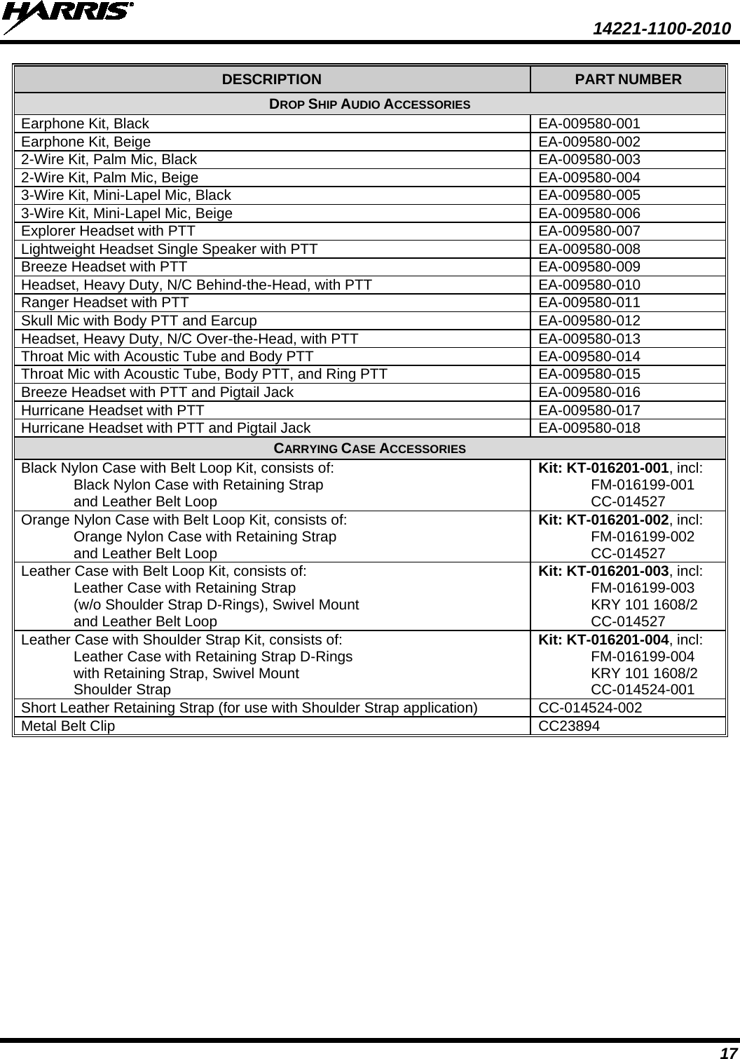
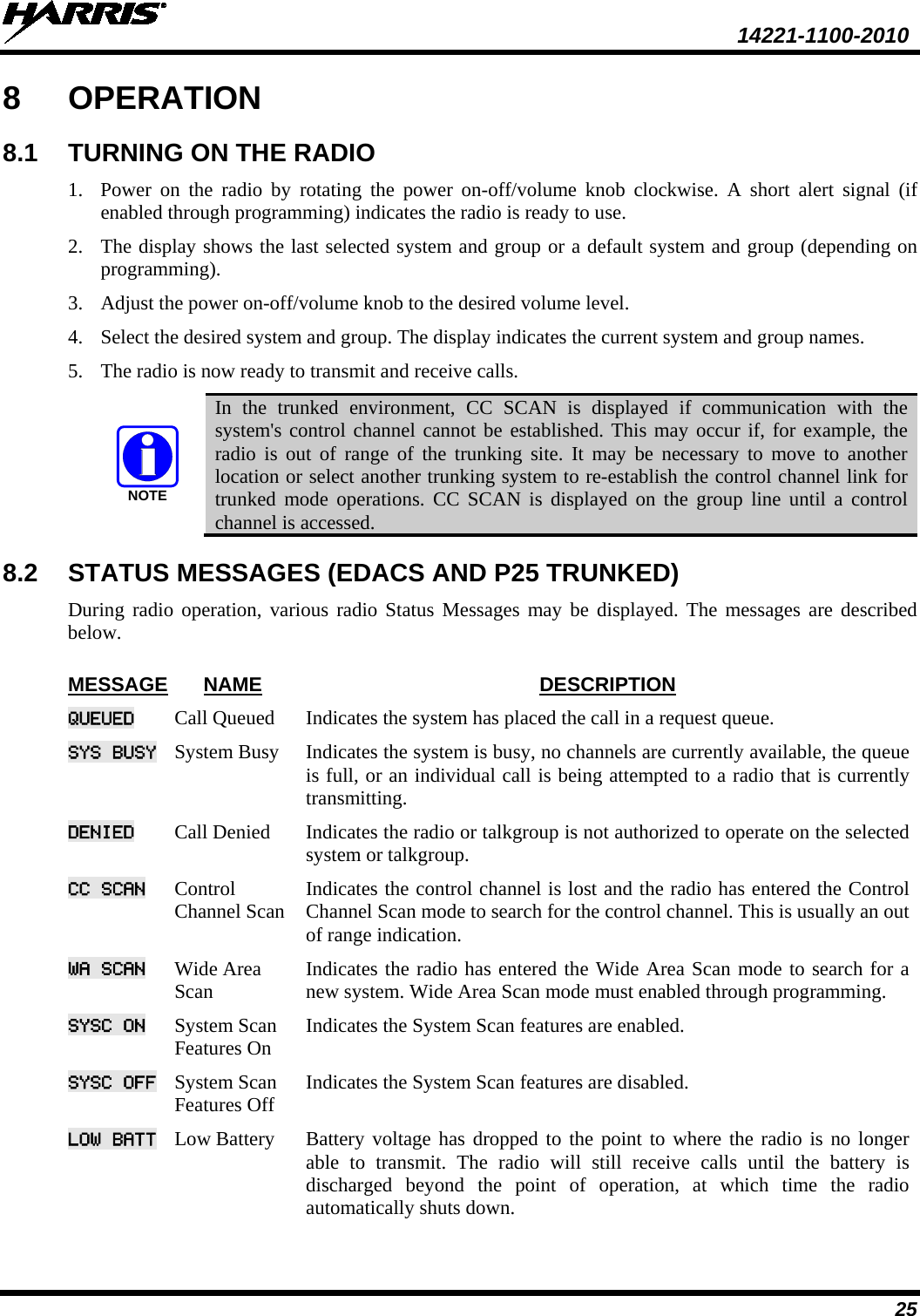
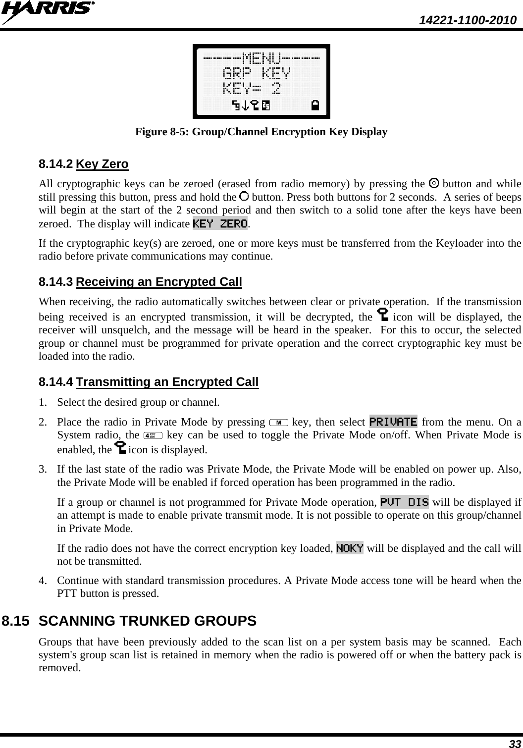
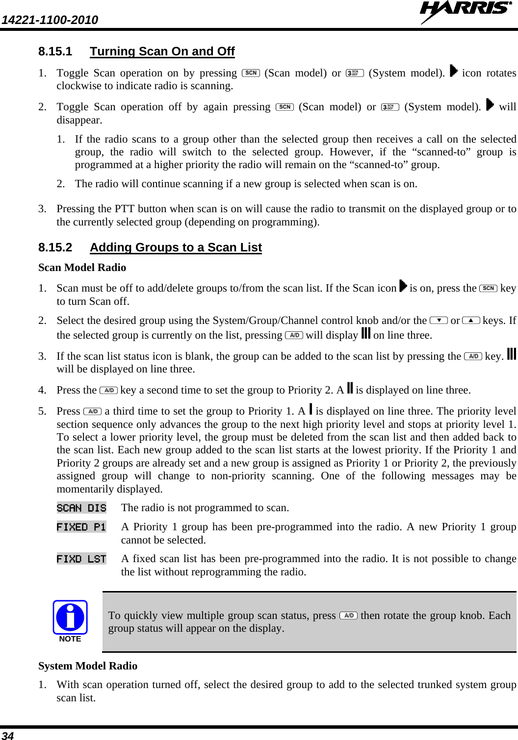
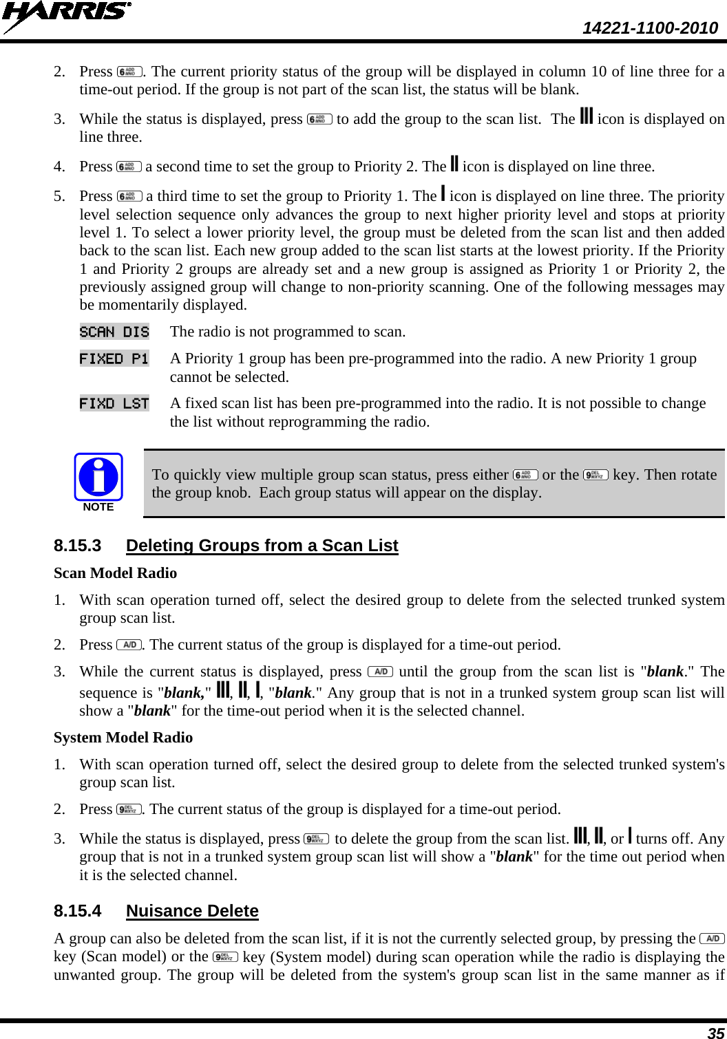
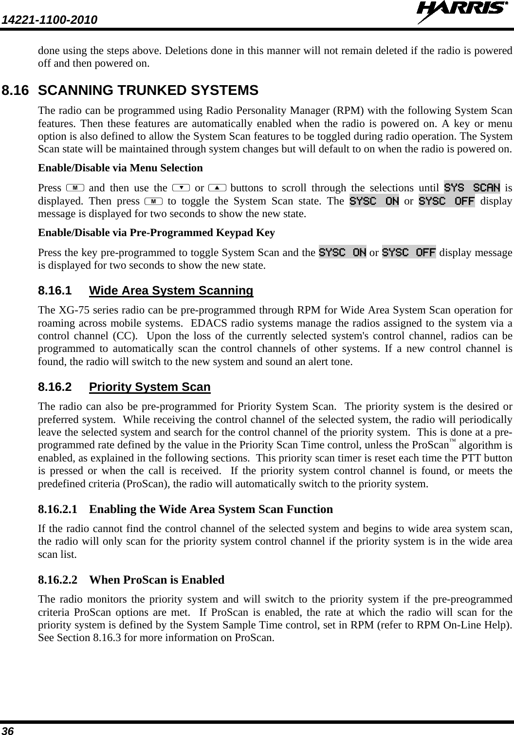
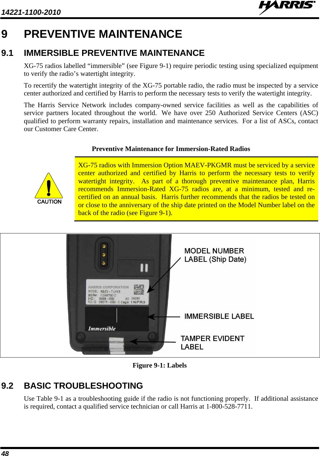
![14221-1100-2010 16 6 OPTIONS AND ACCESSORIES Table 6-1 lists the Options and Accessories tested for use with the XG-75 series portable radios. Refer to the maintenance manual corresponding to the frequency of your XG-75 or to Harris Products and Services Catalog for a complete list of options and accessories, including those items that do not adversely affect the RF energy exposure. WARNING Always use Harris authorized accessories (antennas, batteries, belt clips, speaker/mics, etc). Use of unauthorized accessories may cause the FCC Occupational/Controlled Exposure RF compliance requirements to be exceeded. (Refer to Table 2-1.) CAUTION Always use the correct options and accessories (battery, antenna, speaker/mic, etc.) for the radio. Immersion rated options must be used with an immersion rated radio. Factory Mutual options must be used with Factory Mutual certified radios. (Refer to Table 6-1.) Table 6-1: Options and Accessories DESCRIPTION PART NUMBER ANTENNAS Helical coil (136-151 MHz) KRE 101 1219/1 Helical coil (150-162 MHz) KRE 101 1219/2 Helical coil (162-174 MHz) KRE 101 1219/3 Helical coil (150-174 MHz) KRE 101 1219/21 Helical stub (378-403 MHz) KRE 101 1219/9 Helical stub (403-430 MHz) KRE 101 1219/10 1/4 - wave whip (378-430 MHz) KRE 101 1223/10 1/4 - wave whip (430-470 MHz) KRE 101 1223/12 Helical stub (430-470 MHz) KRE 101 1219/12 Helical stub (470-512 MHz) KRE 101 1219/14 1/4 - wave whip (450-512 MHz) KRE 101 1223/12 Wideband whip (764-870 MHz) KRE 101 1506/02 1/2 - wave (764-870 MHz) KRE 101 1506/01 BATTERIES (IMMERSION-RATED) NiMH, immersible, Goldpeak cells, non-IS BT-023406-103 Nickel Metal Hydride (NiMH) Battery, Immersible, non-[FM] BT-023406-003 Nickel Metal Hydride (NiMH) Battery, Immersible, [FM] BT-023406-004 Lithium Ion (Li-Ion) Battery, Immersible, non-[FM] BT-023406-005 MISCELLANEOUS ACCESSORIES Speaker Mic without Antenna (cc) provision, [FM] MC-023933-001 Speaker Mic with Antenna (cc) provision, [FM] MC-023933-002 Earphone for Speaker Mic [FM] LS103239V1 GPS, non-IS MC-009104-002 Ruggedized Speaker Mic-Coil Cord MC-011617-601 Standard Speaker Mic - Non Ant MC-011617-701](https://usermanual.wiki/HARRIS/TR-0059-E.Manual-1/User-Guide-1540143-Page-16.png)