HARRIS TR-0062-E M7300 440-512MHz 50W User Manual Manual 1
HARRIS CORPORATION M7300 440-512MHz 50W Manual 1
UserManual.wiki
>
HARRIS
>
TR-0062-E User Manual
>
Manual 1
Contents
1.
Manual 1
2.
Manual 2
Manual 1
Navigation menu
Upload a User Manual
Namespaces
Wiki Guide
HTML
PDF
Info
Views
User Manual
Discussion / Help
Navigation

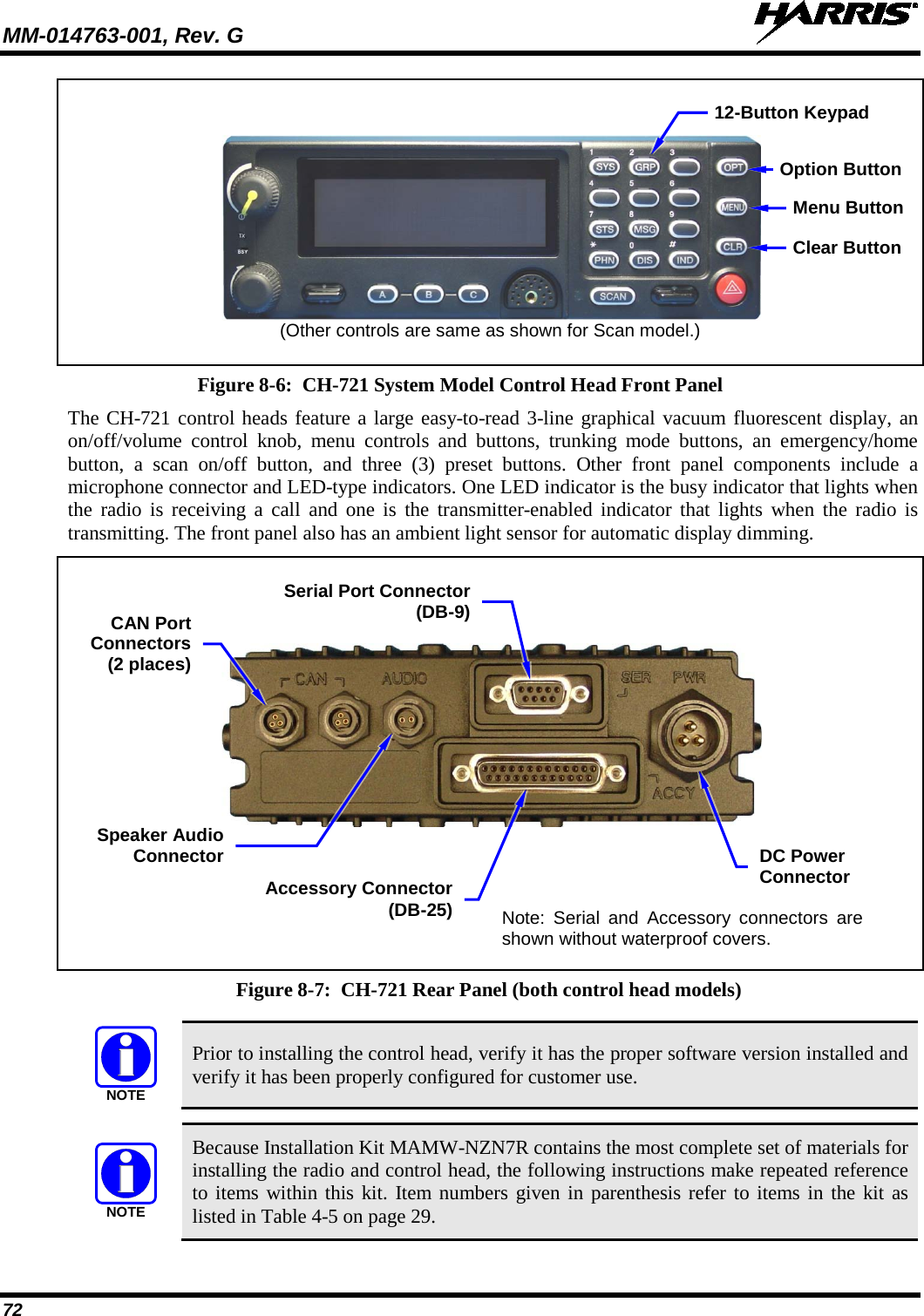
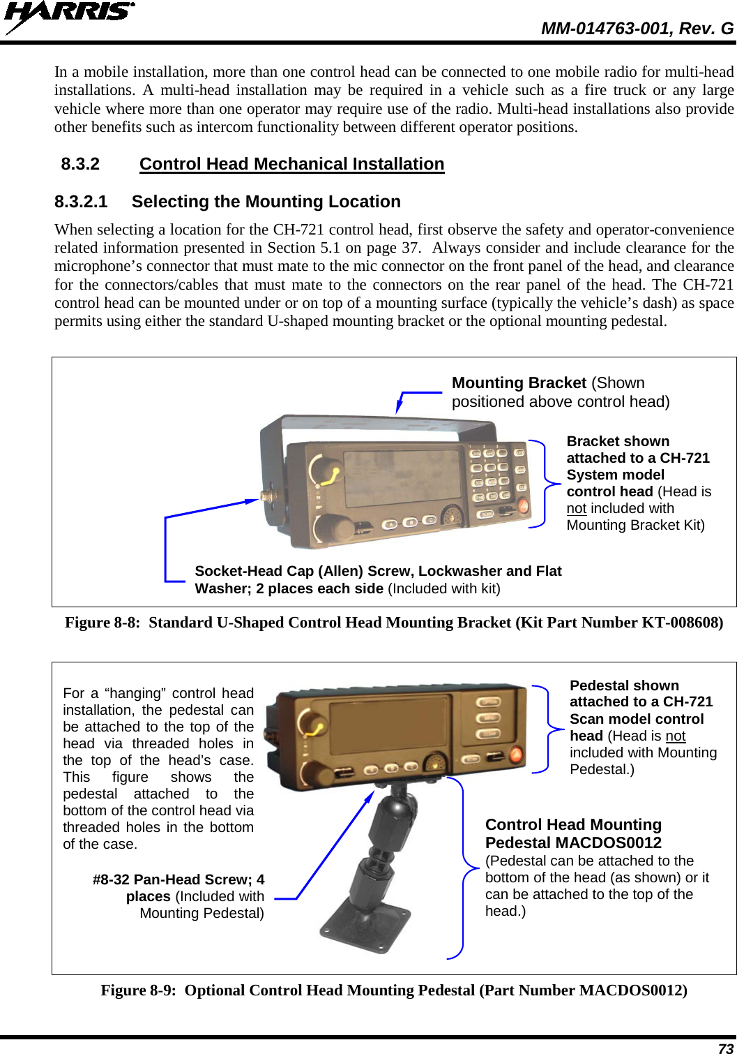
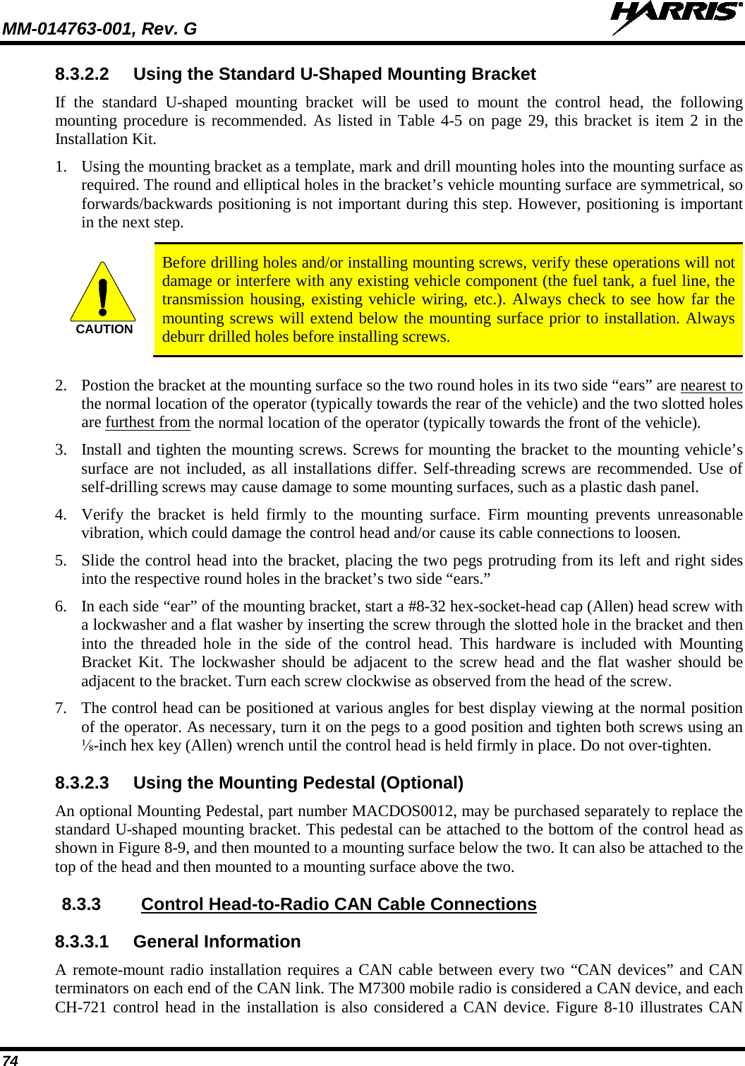
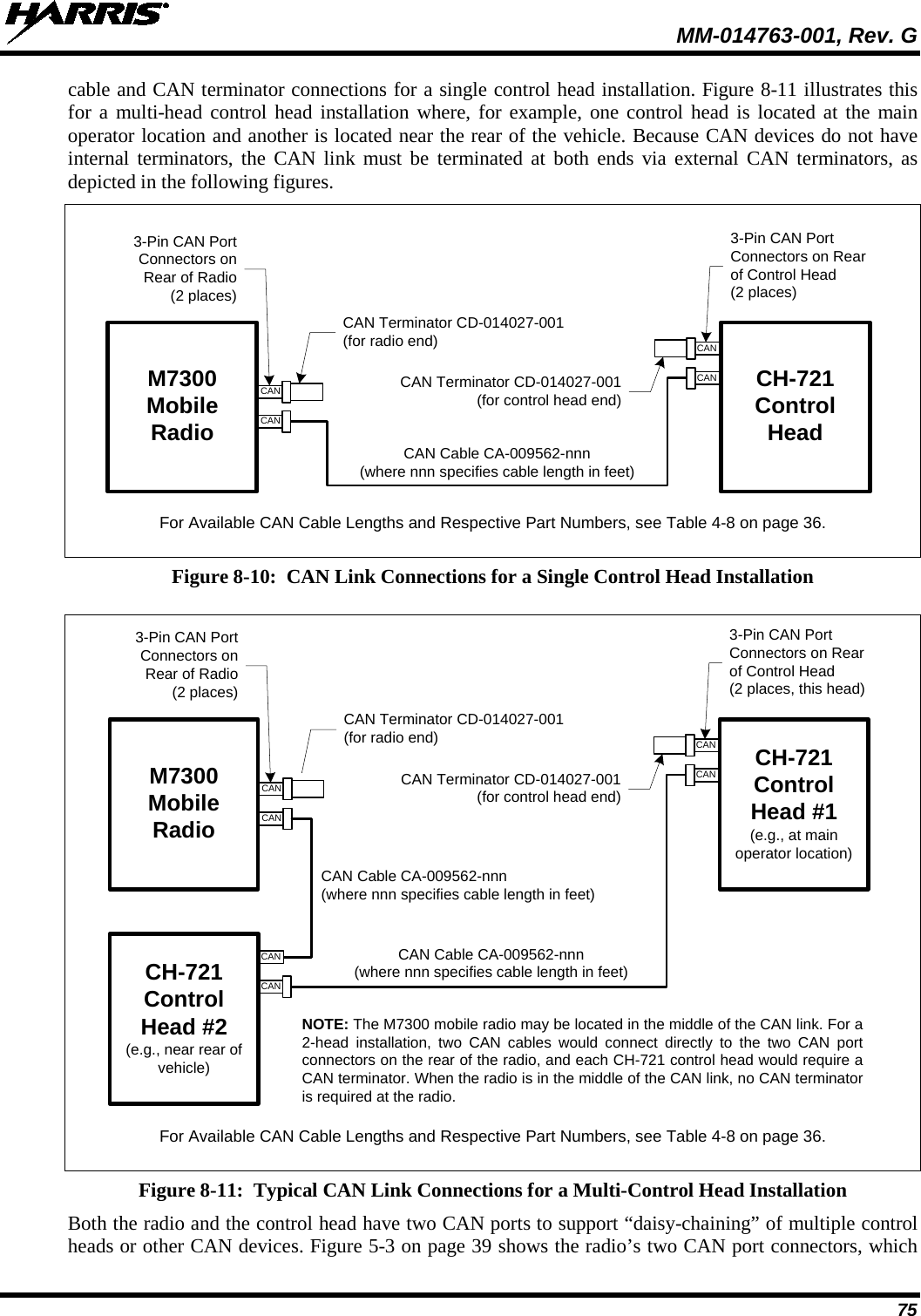
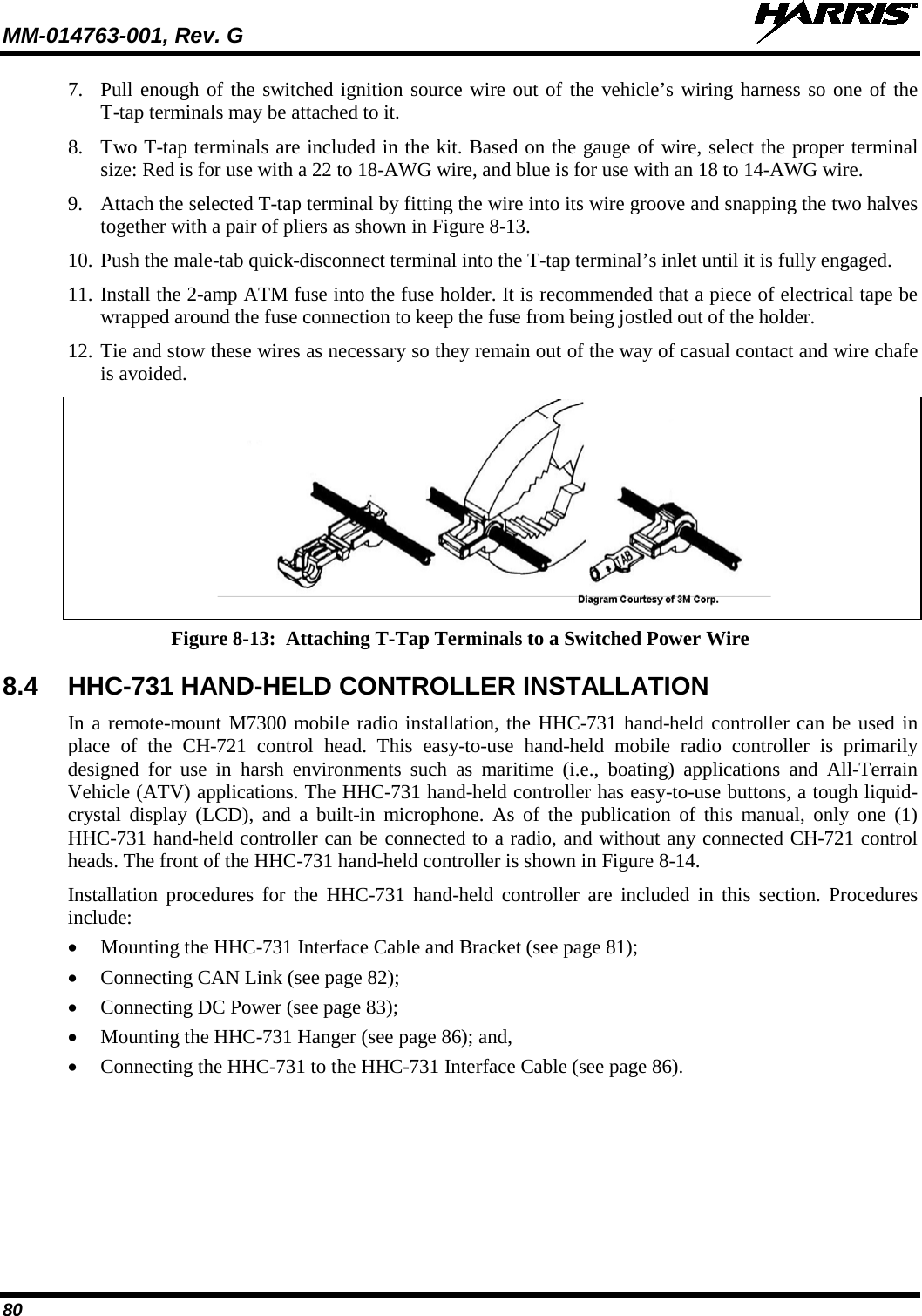
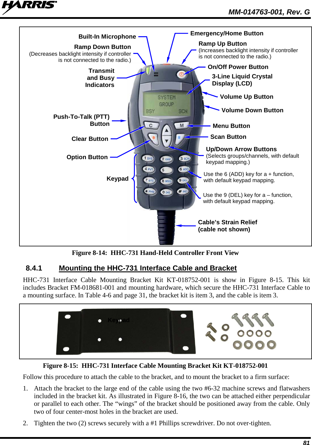
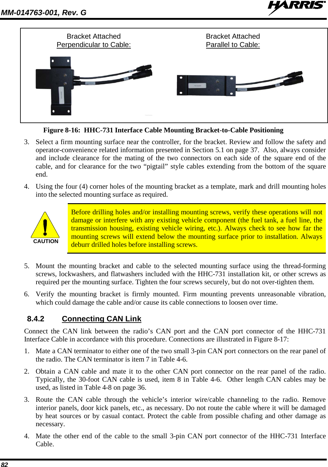
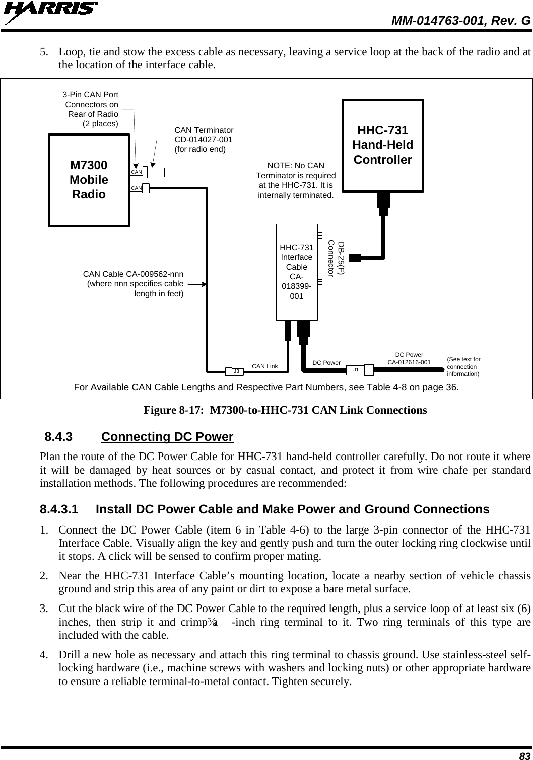
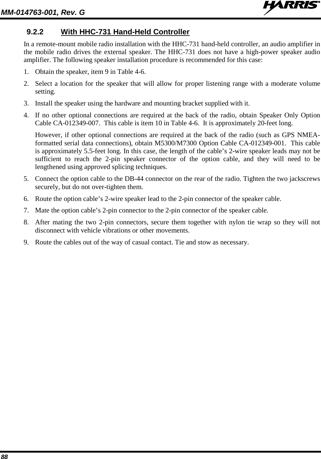
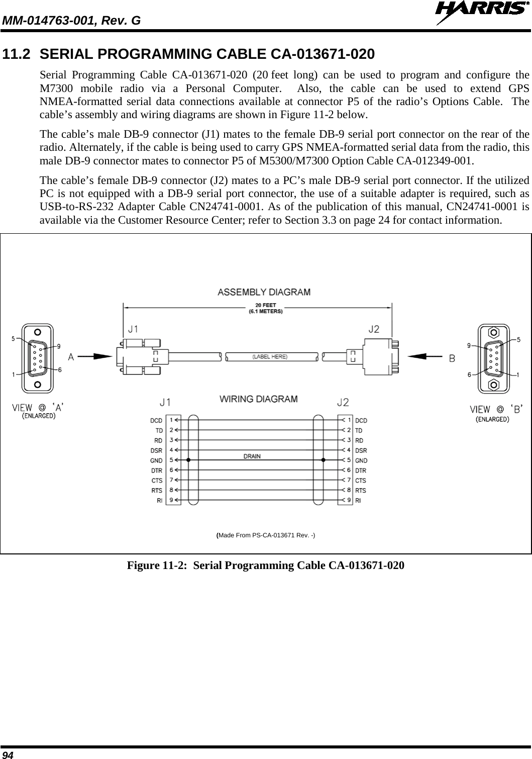
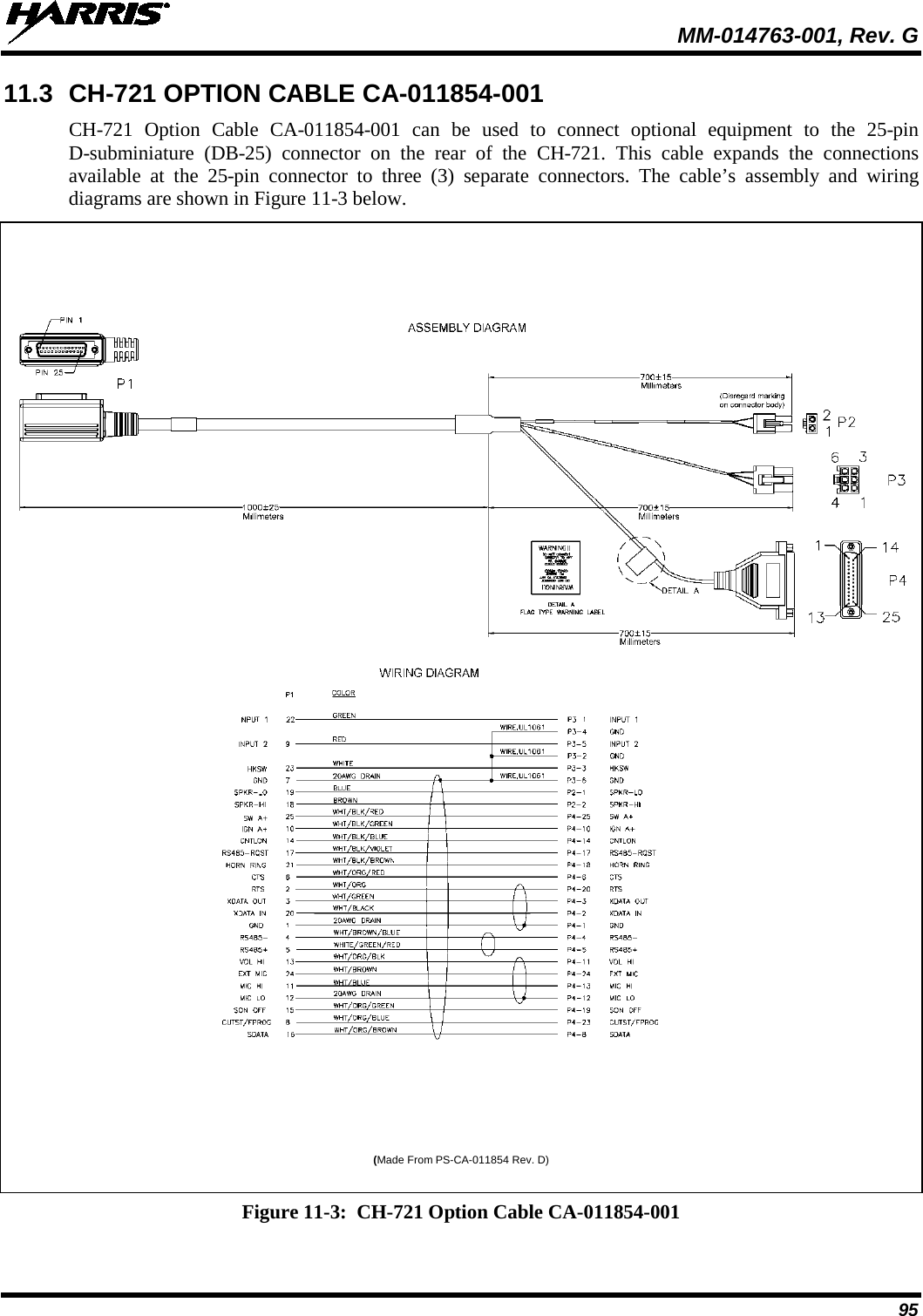
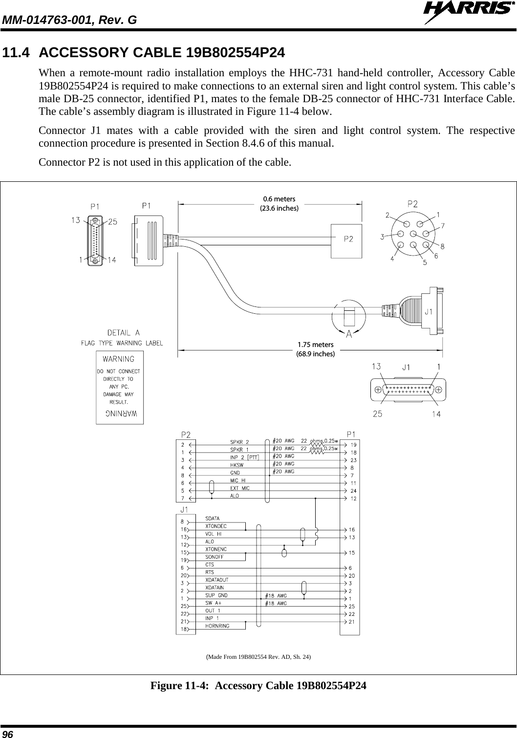
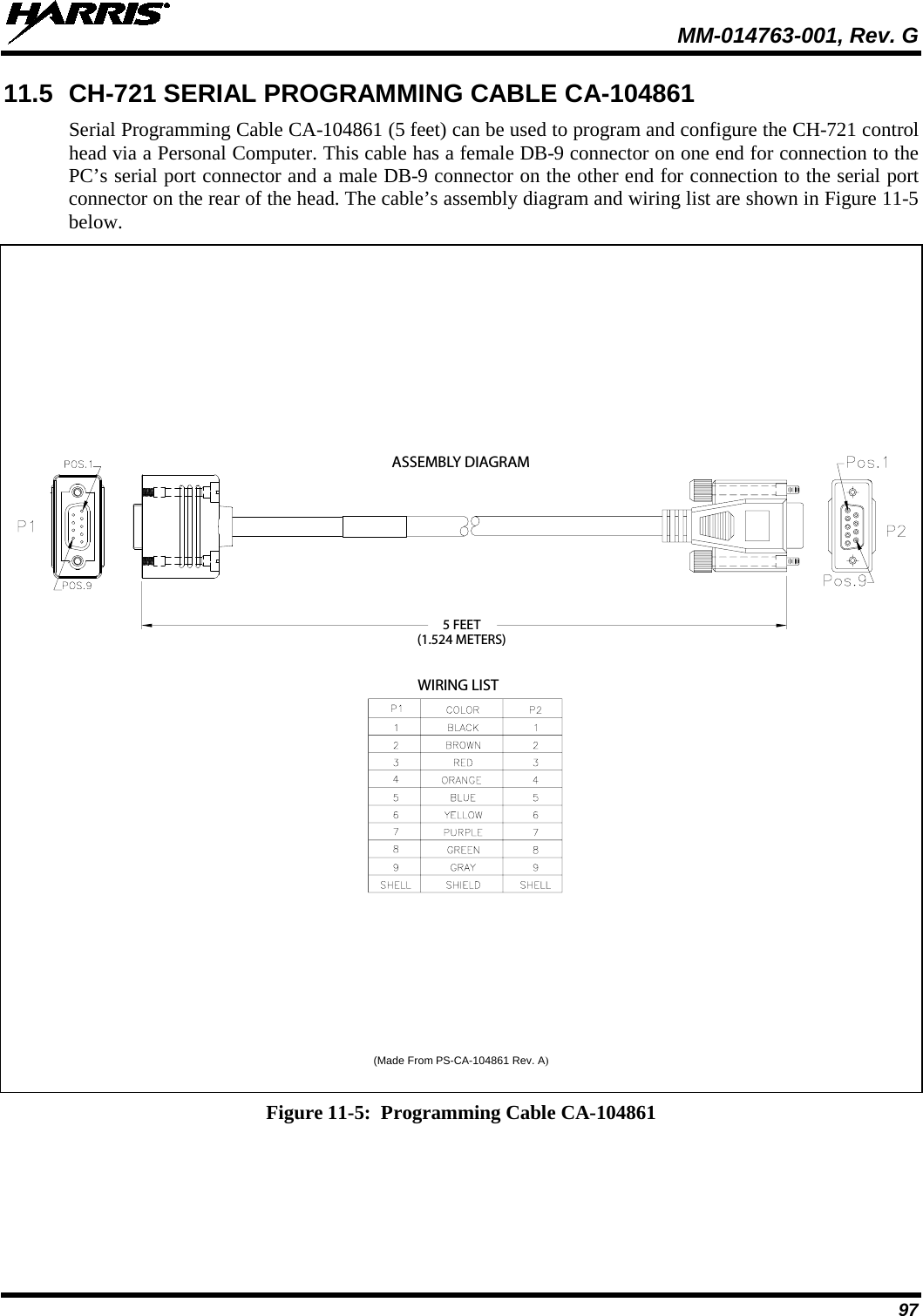
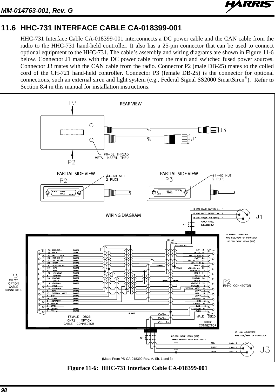
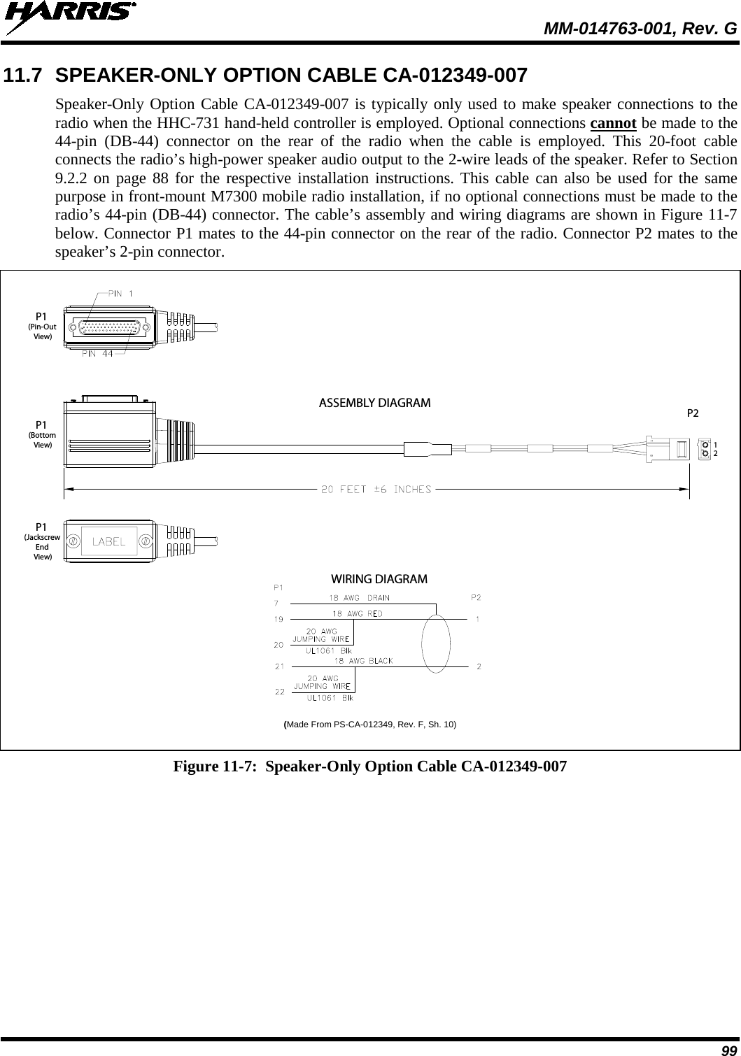
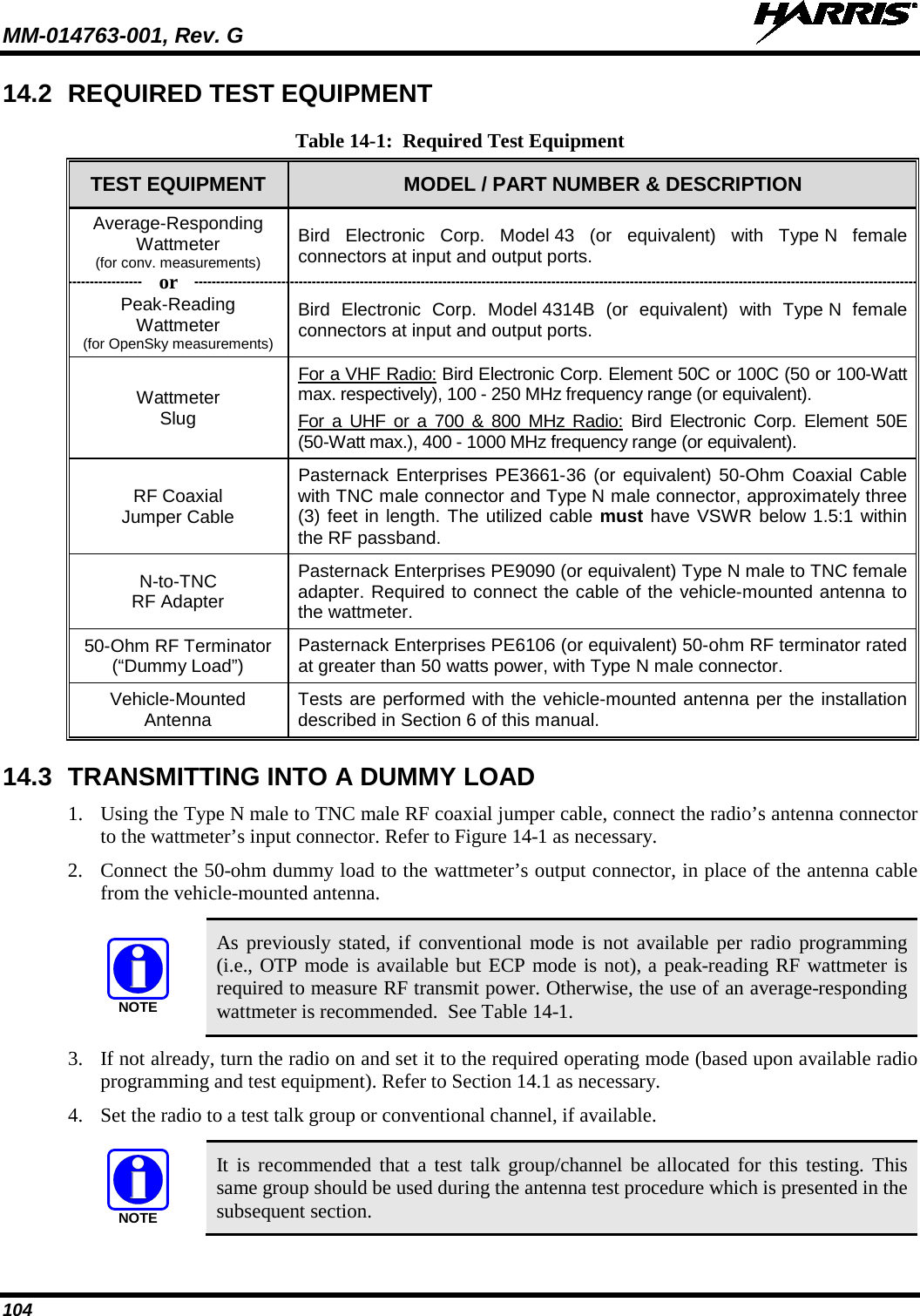
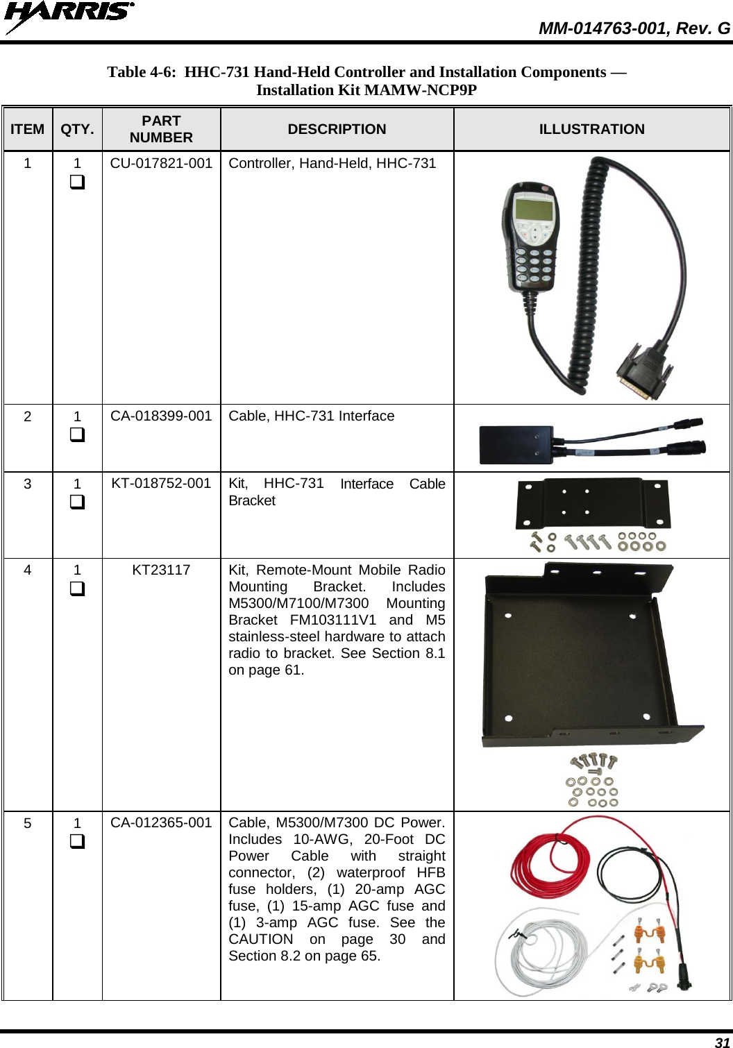
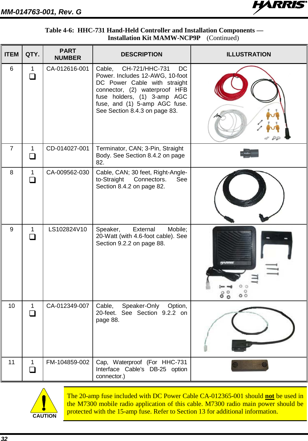
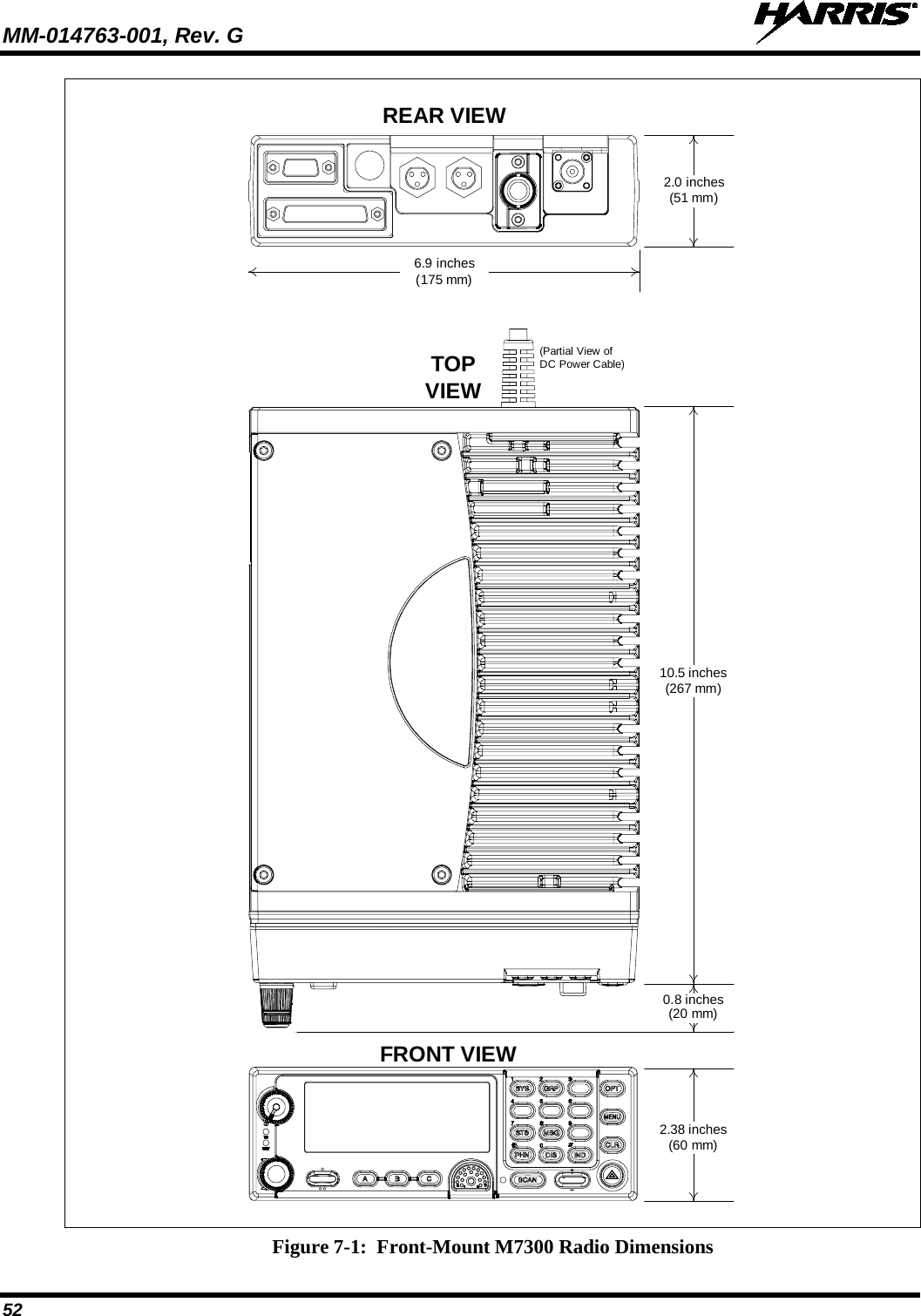
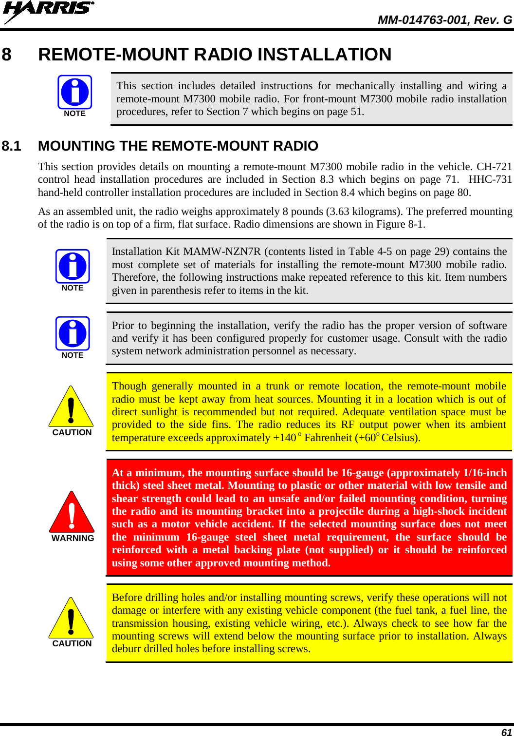
![MM-014763-001, Rev. G 5 TABLE OF CONTENTS Section Page 14.4 TRANSMITTING INTO THE MOBILE ANTENNA ...................................................................... 106 14.5 TEST PERFORMANCE DATA FORM ........................................................................................... 109 15 COMPLETE THE INSTALLATION ..................................................................................................... 110 16 WARRANTY REGISTRATION ............................................................................................................. 110 17 WARRANTY ............................................................................................................................................. 111 LIST OF FIGURES Page Figure 5-1: Typical Front-Mount Mobile Radio Installation in a Standard Passenger Vehicle .......................... 38 Figure 5-2: Typical Remote-Mount Mobile Radio Installation in a Standard Passenger Vehicle ....................... 38 Figure 5-3: M7300 Front-Mount and Remote-Mount Mobile Radios — Front and Rear Views ........................ 39 Figure 6-1: Recommended Antenna Mounting Locations with Antenna Part Numbers ..................................... 44 Figure 6-2: Installing a Standard ¾-Inch NMO Antenna Mount (e.g., AN-125001-001 or AN-125001-002) ... 46 Figure 6-3: Installing a Thick-Roof NMO Antenna Mount (e.g., AN-125001-003 or AN-125001-004) ........... 47 Figure 6-4: Crimping Instructions for TNC RF Connector ................................................................................. 49 Figure 7-1: Front-Mount M7300 Radio Dimensions ........................................................................................... 52 Figure 7-2: Front-Mount Mounting Bracket Kit KT101533V1 .......................................................................... 53 Figure 7-3: Mounting Bracket FM101319V1 (Marked KTB0310) Dimensions [for Front-Mount M7300 Mobile Radio (Radio Not Shown)] .............................................................................................. 54 Figure 8-1: Remote-Mount M7300 Radio Dimensions ....................................................................................... 62 Figure 8-2: Remote-Mount Mounting Bracket Kit KT23117 ............................................................................. 63 Figure 8-3: Mounting Bracket FM103111V1 Dimensions [for Remote-Mount M7300 Mobile Radio (Radio Not Shown)] ..................................................................................................................... 64 Figure 8-4: Wiring Diagram for a Remote-Mount Radio Installation ................................................................. 66 Figure 8-5: CH-721 Scan Model Control Head Front Panel ............................................................................... 71 Figure 8-6: CH-721 System Model Control Head Front Panel ........................................................................... 72 Figure 8-7: CH-721 Rear Panel (both control head models) ............................................................................... 72 Figure 8-8: Standard U-Shaped Control Head Mounting Bracket (Kit Part Number KT-008608) ..................... 73 Figure 8-9: Optional Control Head Mounting Pedestal (Part Number MACDOS0012) ..................................... 73 Figure 8-10: CAN Link Connections for a Single Control Head Installation ..................................................... 75 Figure 8-11: Typical CAN Link Connections for a Multi-Control Head Installation ......................................... 75 Figure 8-12: Contents of Vehicle Fuse and T-Tap Kit FS24473 ......................................................................... 79 Figure 8-13: Attaching T-Tap Terminals to a Switched Power Wire .................................................................. 80 Figure 8-14: HHC-731 Hand-Held Controller Front View ................................................................................. 81 Figure 8-15: HHC-731 Interface Cable Mounting Bracket Kit KT-018752-001 ................................................ 81 Figure 8-16: HHC-731 Interface Cable Mounting Bracket-to-Cable Positioning ............................................... 82 Figure 8-17: M7300-to-HHC-731 CAN Link Connections ................................................................................ 83 Figure 10-1: Attaching the Microphone to the CH-721Control Head ................................................................. 89 Figure 11-1: M5300/M7300 Option Cable CA-012349-001 ............................................................................... 90 Figure 11-2: Serial Programming Cable CA-013671-020 ................................................................................... 94 Figure 11-3: CH-721 Option Cable CA-011854-001 .......................................................................................... 95 Figure 11-4: Accessory Cable 19B802554P24.................................................................................................... 96 Figure 11-5: Programming Cable CA-104861 .................................................................................................... 97 Figure 11-6: HHC-731 Interface Cable CA-018399-001 .................................................................................... 98 Figure 11-7: Speaker-Only Option Cable CA-012349-007 ................................................................................. 99 Figure 14-1: Wattmeter Connections for Antenna System Tests ...................................................................... 105 (Continued)](https://usermanual.wiki/HARRIS/TR-0062-E.Manual-1/User-Guide-1349711-Page-5.png)
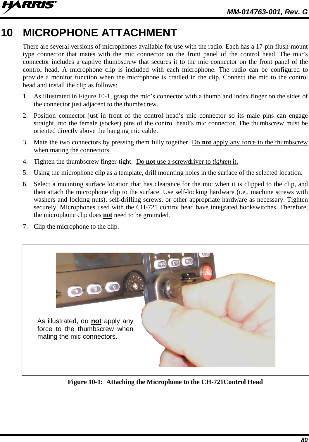
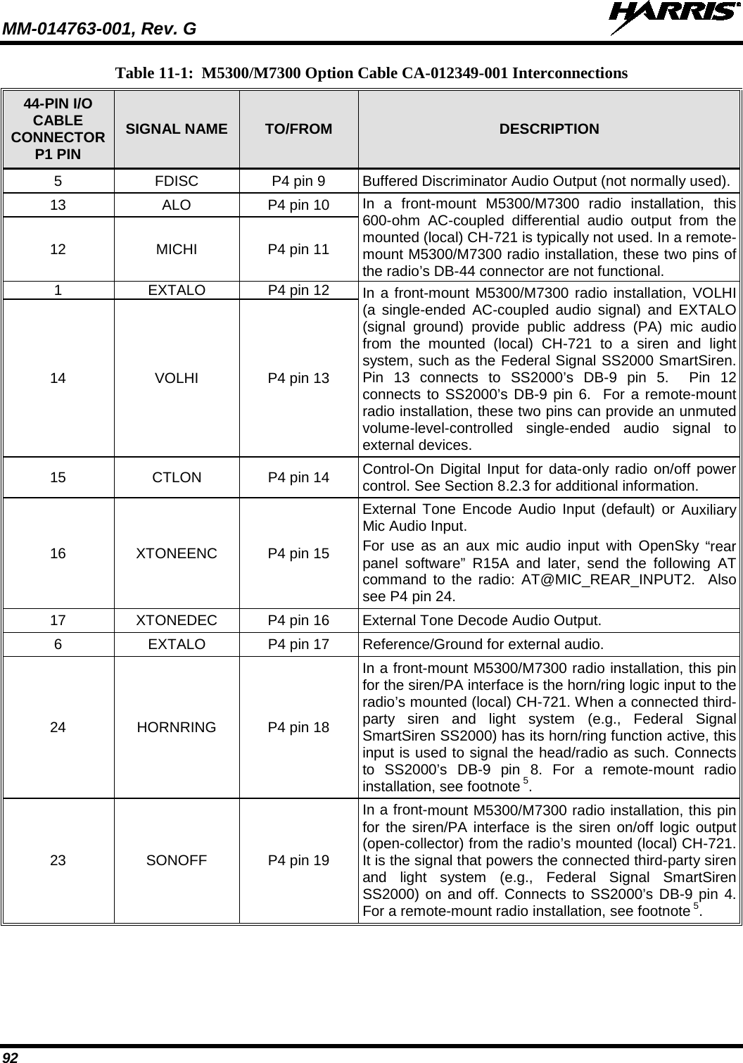
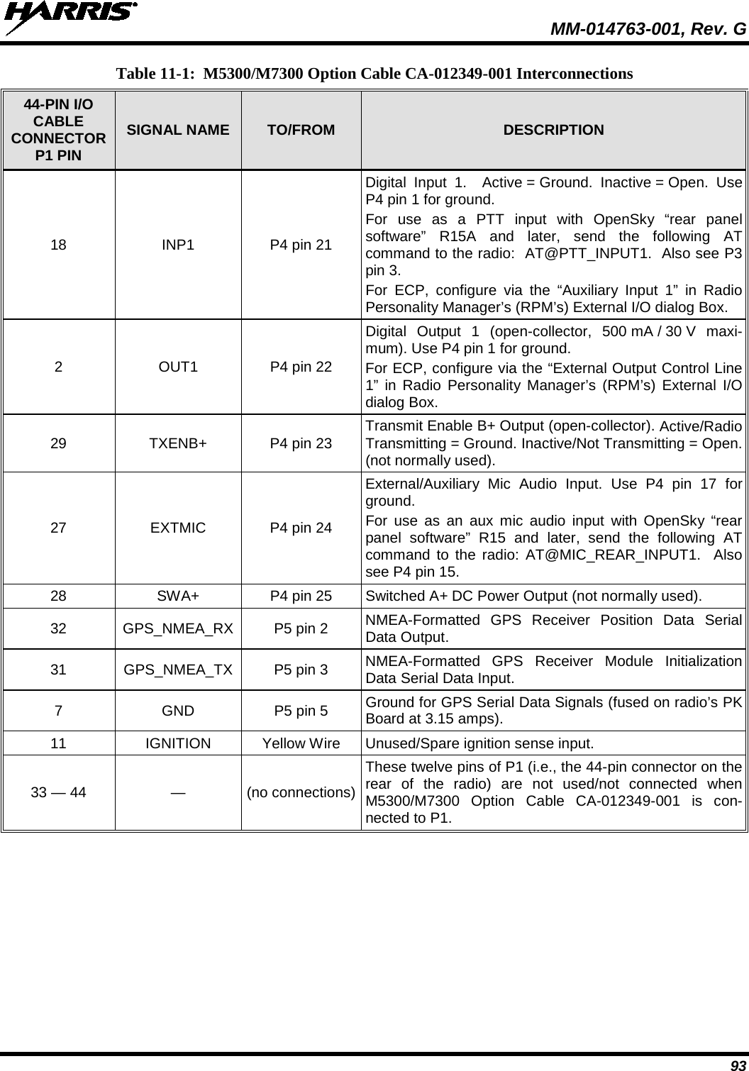
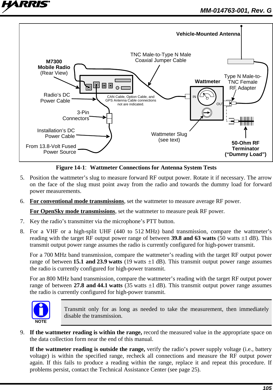
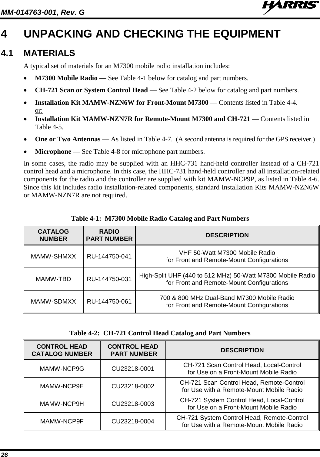
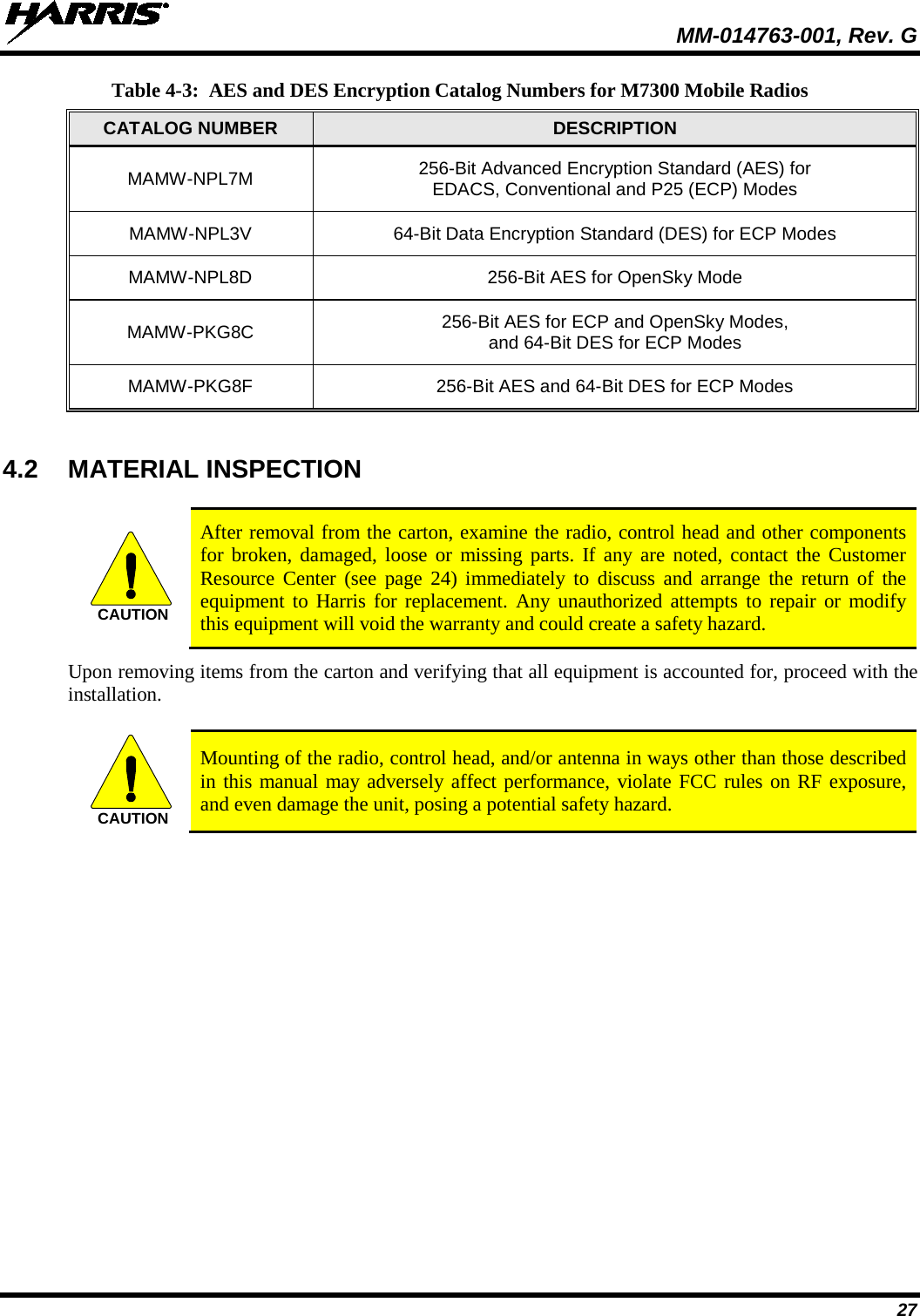
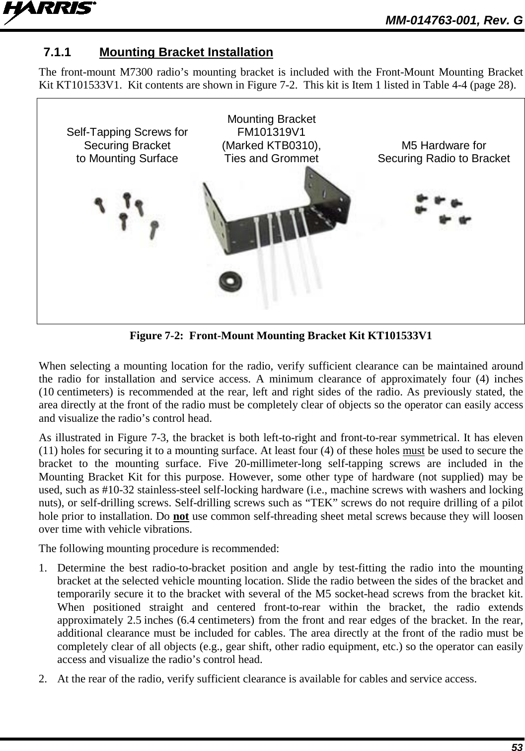
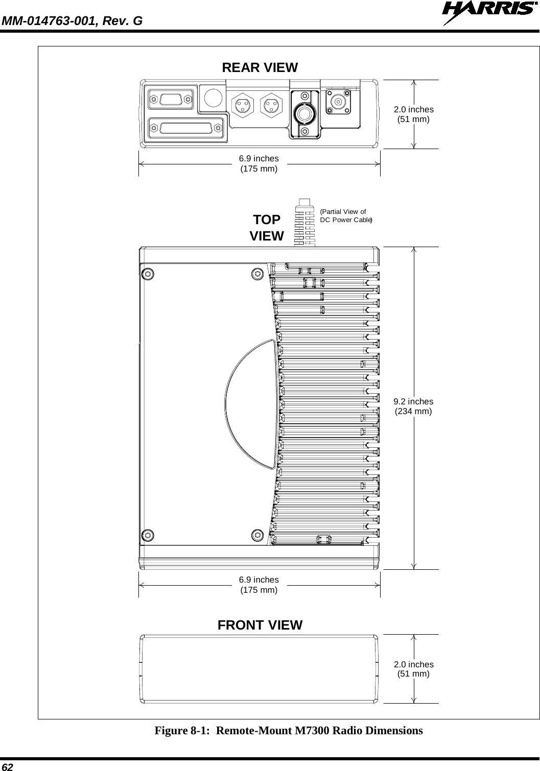
![MM-014763-001, Rev. G 6 LIST OF TABLES Page Table 1-1: Recommended Minimum Safe Lateral Distance from Transmitting Antenna Connected to a VHF M7300 Mobile Radio (“M7300 VHF 50-Watt”) .................................................................. 9 Table 1-2: Recommended Minimum Safe Lateral Distance from a Transmitting Antenna Connected to a High-Split UHF M7300 Mobile Radio (“M7300 440 to 512 MHz 50-Watt”) ............................ 10 Table 1-3: Recommended Minimum Safe Lateral Distance from a Transmitting Antenna Connected to a 700/800 MHz M7300 Mobile Radio [“M7300 (700/800 MHz)”] ............................................... 11 Table 3-1: Radio Systems/Standards Supported by the M7300 Mobile Radio .................................................... 21 Table 4-1: M7300 Mobile Radio Catalog and Part Numbers .............................................................................. 26 Table 4-2: CH-721 Control Head Catalog and Part Numbers ............................................................................. 26 Table 4-3: AES and DES Encryption Catalog Numbers for M7300 Mobile Radios ........................................... 27 Table 4-4: Installation Kit MAMW-NZN6W for Front-Mount M7300 Mobile Radio ....................................... 28 Table 4-5: Installation Kit MAMW-NZN7R for Remote-Mount M7300 Mobile Radio with CH-721 Control Head ................................................................................................................................ 29 Table 4-6: HHC-731 Hand-Held Controller and Installation Components — Installation Kit MAMW-NCP9P ......................................................................................................................................... 31 Table 4-7: Additional Options and Accessories for M7300 Mobile Radios ........................................................ 33 Table 4-8: Additional Options and Accessories for CH-721 Control Heads ....................................................... 36 Table 11-1: M5300/M7300 Option Cable CA-012349-001 Interconnections ..................................................... 91 Table 14-1: Required Test Equipment ............................................................................................................... 104](https://usermanual.wiki/HARRIS/TR-0062-E.Manual-1/User-Guide-1349711-Page-6.png)
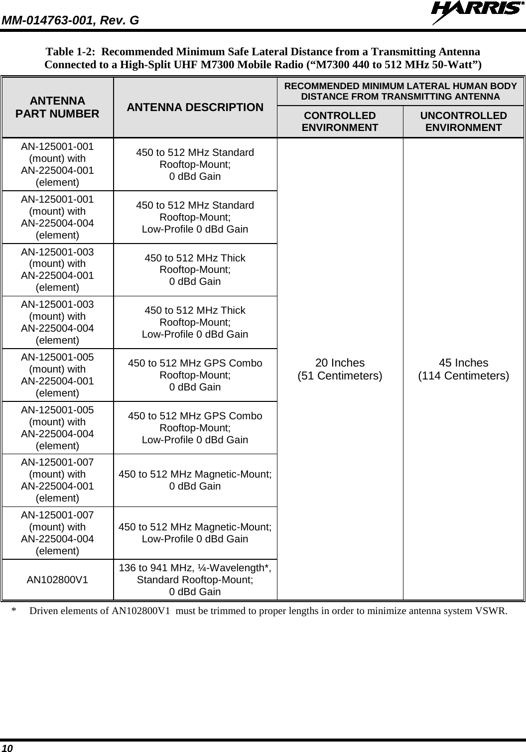
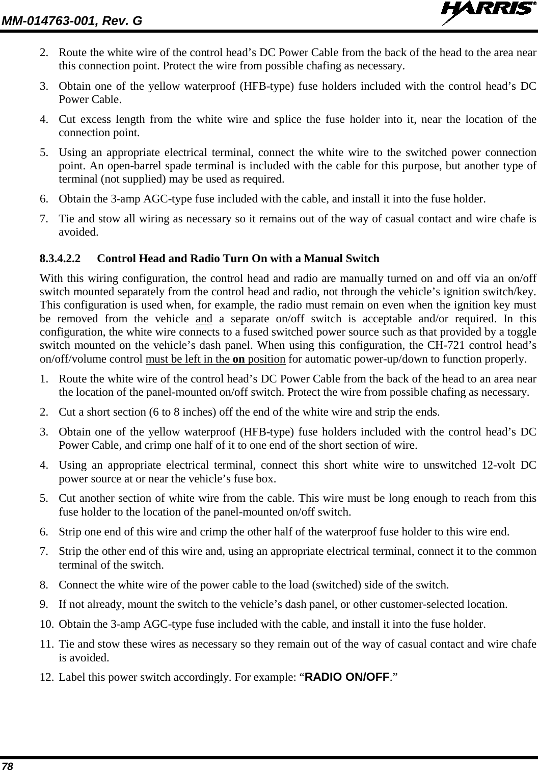
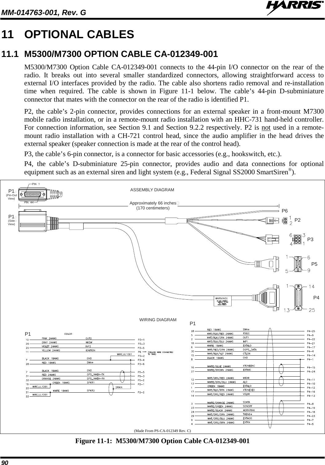
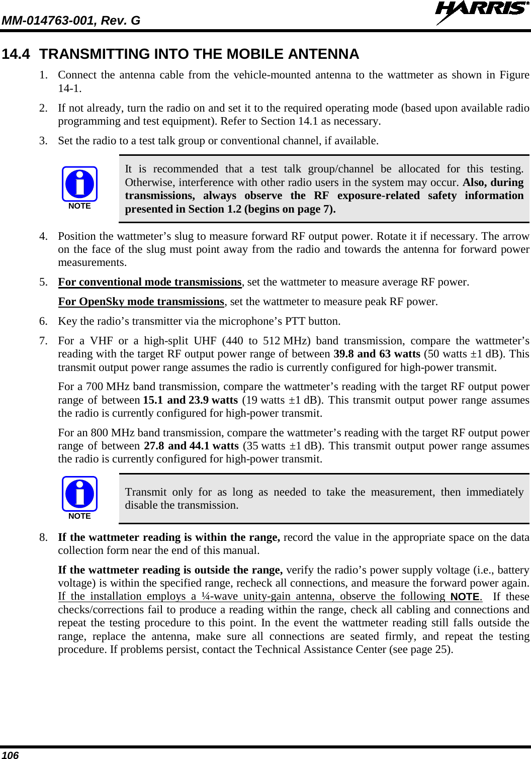
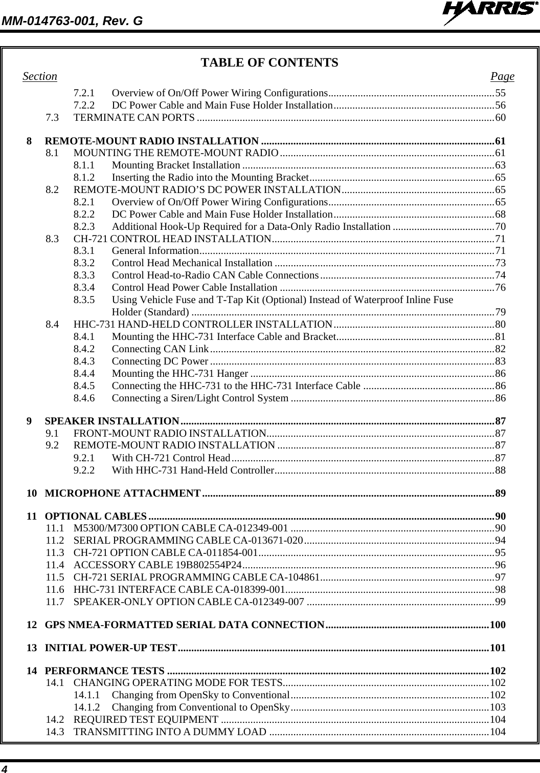
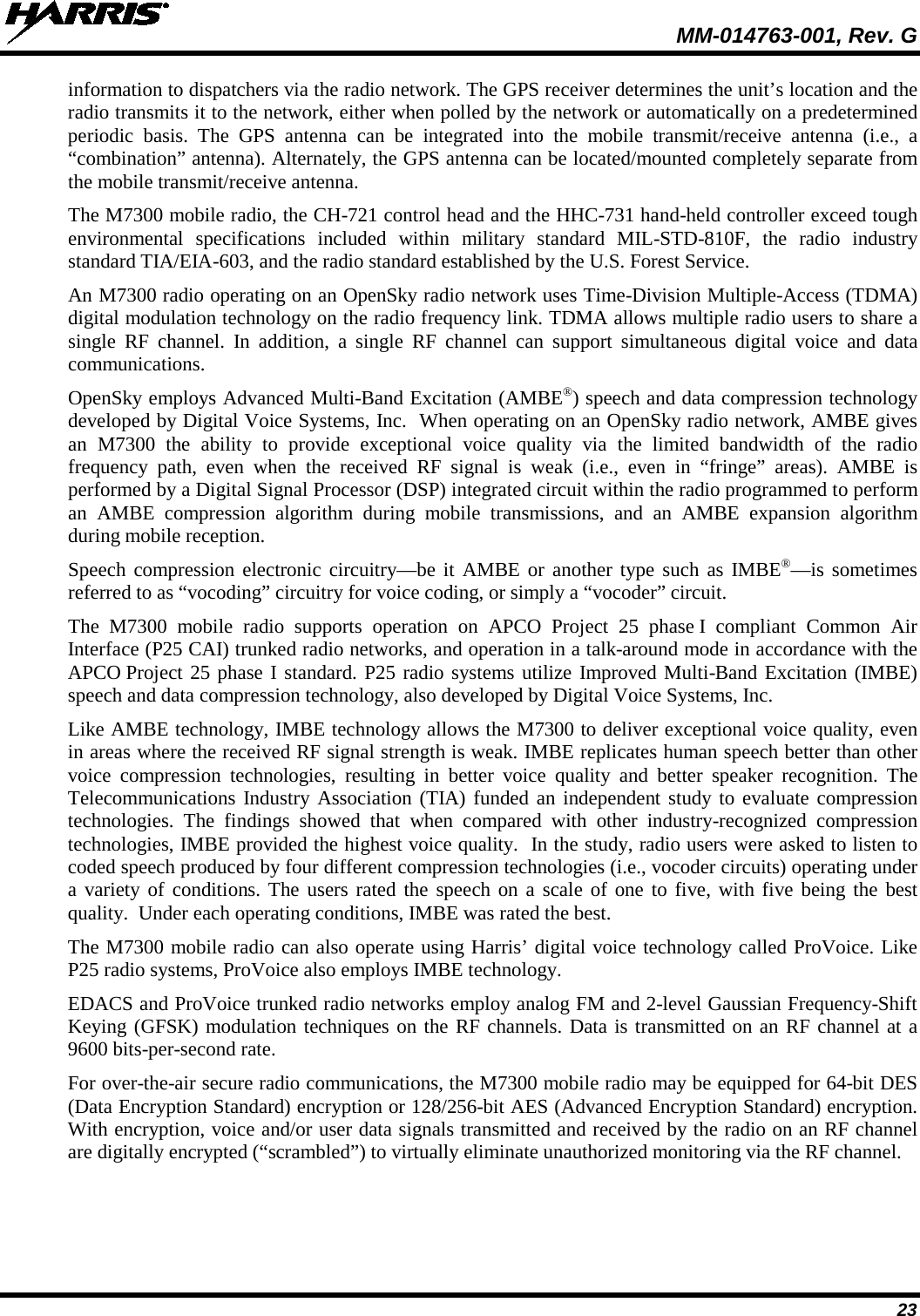
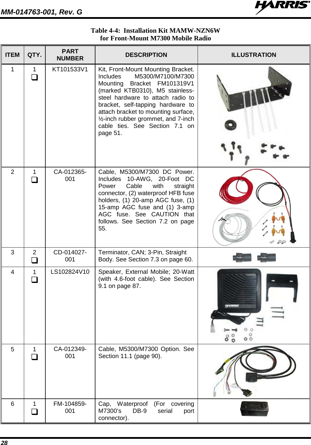
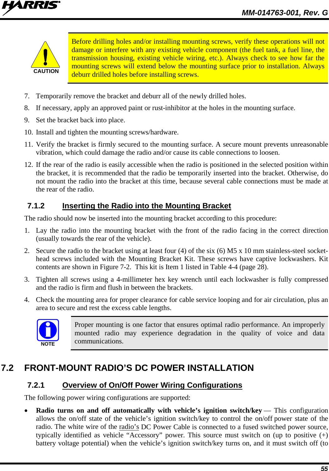
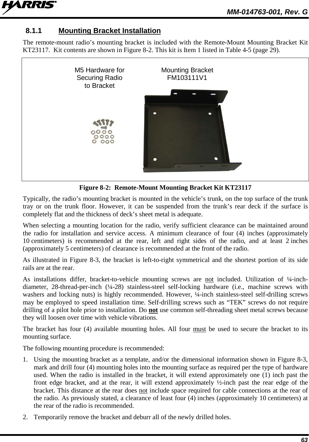
![MM-014763-001, Rev. G 11 Table 1-3: Recommended Minimum Safe Lateral Distance from a Transmitting Antenna Connected to a 700/800 MHz M7300 Mobile Radio [“M7300 (700/800 MHz)”] ANTENNA PART NUMBER ANTENNA DESCRIPTION RECOMMENDED MINIMUM LATERAL HUMAN BODY DISTANCE FROM TRANSMITTING ANTENNA CONTROLLED ENVIRONMENT UNCONTROLLED ENVIRONMENT AN-125001-002 (mount) with AN-225001-001 (element) 700/800 MHz Standard Rooftop-Mount; 3 dBd Gain 9.8 Inches (25 Centimeters) 21.7 Inches (55 Centimeters) AN-125001-002 (mount) with AN-225001-002 (element) 700/800 MHz Standard Rooftop-Mount; Elevated-Feed 3 dBd Gain AN-125001-002 (mount) with AN-225001-003 (element) 700/800 MHz Standard Rooftop-Mount; Elevated-Feed, No Ground Plane 3 dBd Gain AN-125001-002 (mount) with AN-225001-004 (element) 700/800 MHz Standard Rooftop-Mount; Low-Profile 2 dBd Gain AN-125001-002 (mount) with AN-225001-005 (element) 700/800 MHz Standard Rooftop-Mount; 5 dBd Gain 11.8 Inches (30 Centimeters) 23.6 Inches (60 Centimeters) AN-125001-004 (mount) with AN-225001-001 (element) 700/800 MHz Thick Rooftop-Mount; 3 dBd Gain 9.8 Inches (25 Centimeters) 21.7 Inches (55 Centimeters) AN-125001-004 (mount) with AN-225001-002 (element) 700/800 MHz Thick Rooftop-Mount; Elevated-Feed 3 dBd Gain AN-125001-004 (mount) with AN-225001-003 (element) 700/800 MHz Thick Rooftop-Mount; Elevated-Feed, No Ground Plane 3 dBd Gain AN-125001-004 (mount) with AN-225001-004 (element) 700/800 MHz Thick Rooftop-Mount; Low-Profile 2 dBd Gain AN-125001-004 (mount) with AN-225001-005 (element) 700/800 MHz Thick Rooftop-Mount; 5 dBd Gain 11.8 Inches (30 Centimeters) 23.6 Inches (60 Centimeters) (Table Continued on Next Page)](https://usermanual.wiki/HARRIS/TR-0062-E.Manual-1/User-Guide-1349711-Page-11.png)
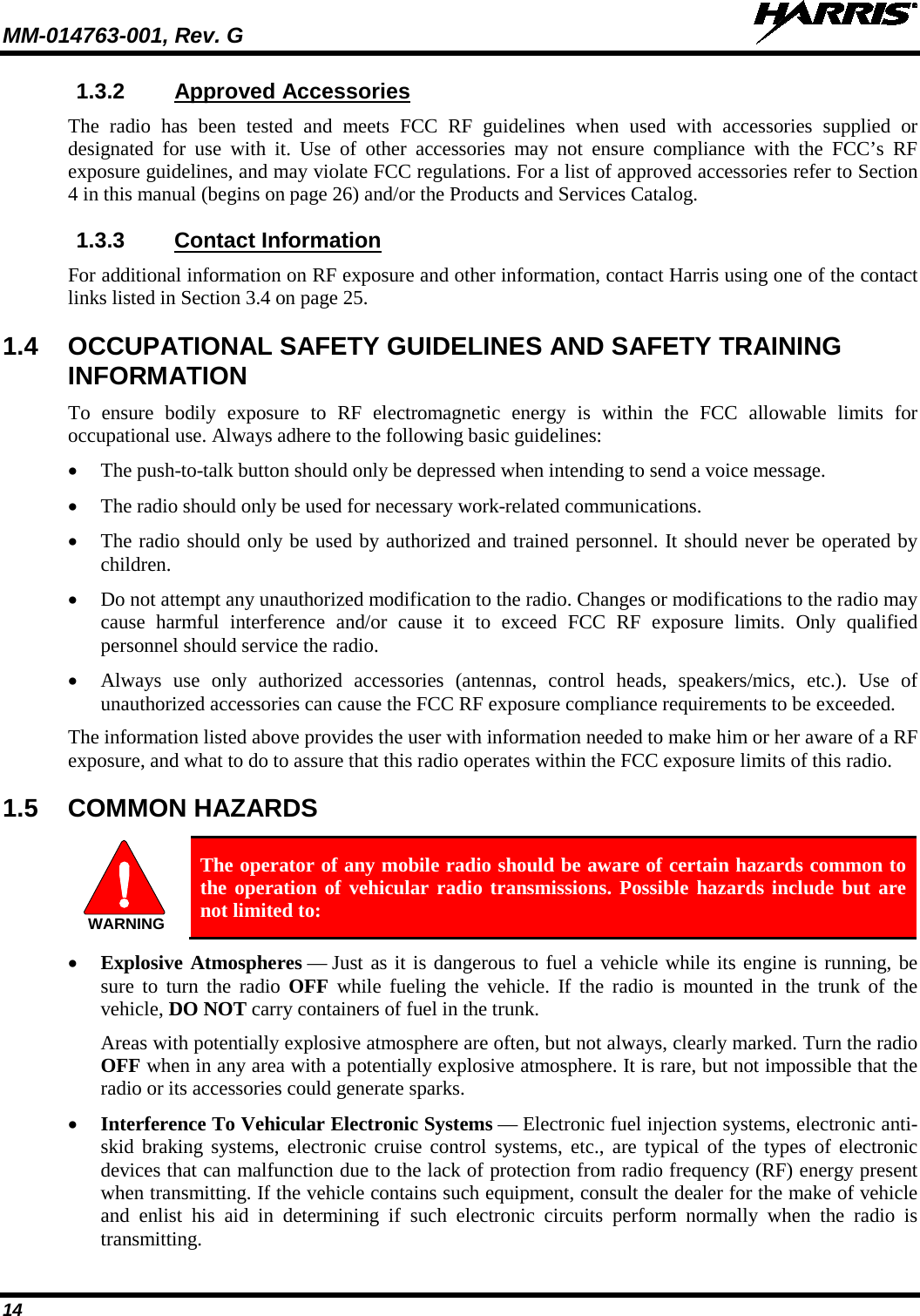
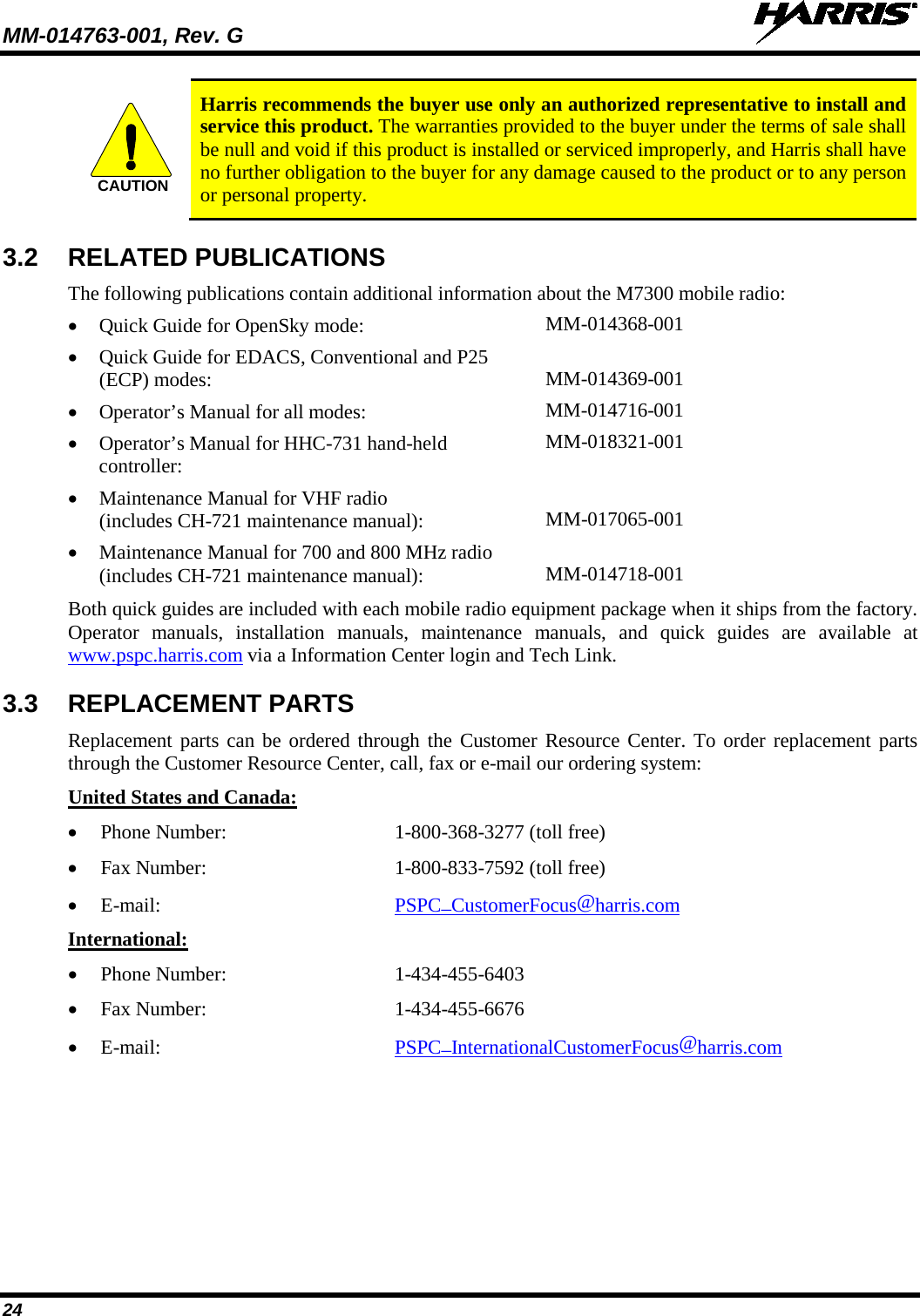
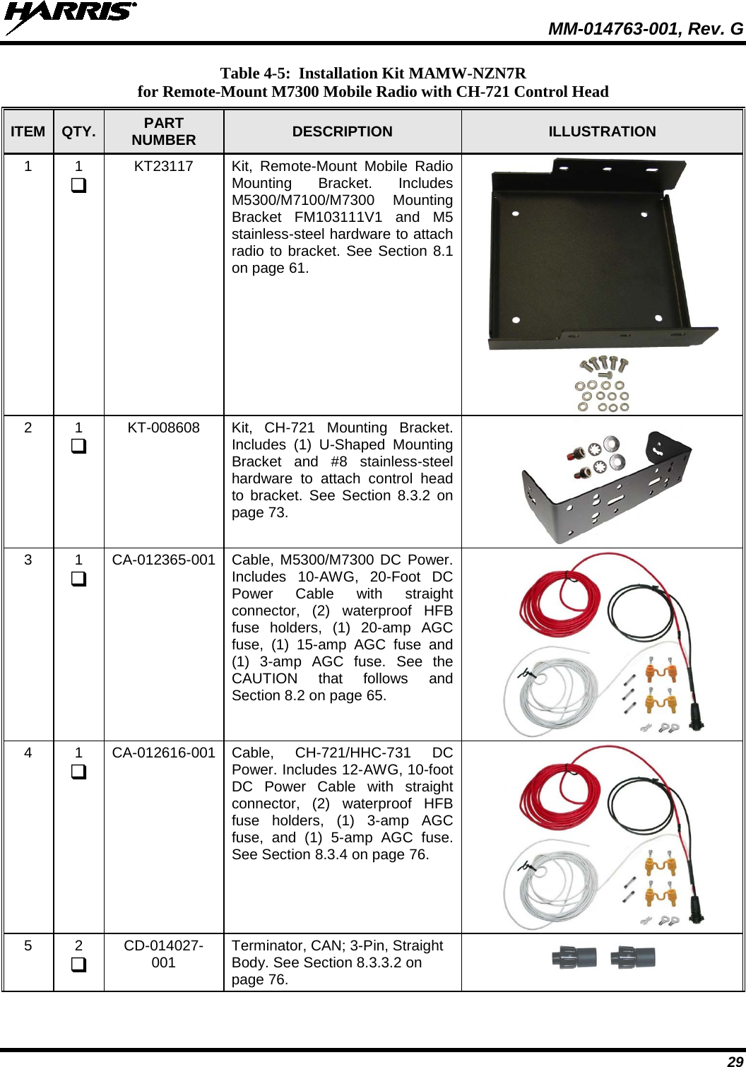
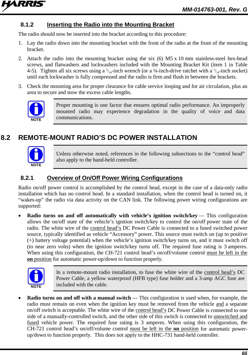
![MM-014763-001, Rev. G 12 Table 1-3: Recommended Minimum Safe Lateral Distance from a Transmitting Antenna Connected to a 700/800 MHz M7300 Mobile Radio [“M7300 (700/800 MHz)”] ANTENNA PART NUMBER ANTENNA DESCRIPTION RECOMMENDED MINIMUM LATERAL HUMAN BODY DISTANCE FROM TRANSMITTING ANTENNA CONTROLLED ENVIRONMENT UNCONTROLLED ENVIRONMENT AN-125001-006 (mount) with AN-225001-001 (element) 700/800 MHz GPS Combo Rooftop-Mount; 3 dBd / 5.15 dBi Gain 9.8 Inches (25 Centimeters) 21.7 Inches (55 Centimeters) AN-125001-006 (mount) with AN-225001-002 (element) 700/800 MHz GPS Combo Rooftop-Mount; Elevated-Feed 3 dBd Gain AN-125001-006 (mount) with AN-225001-003 (element) 700/800 MHz GPS Combo Rooftop-Mount; Elevated-Feed, No Ground Plane 3 dBd Gain AN-125001-006 (mount) with AN-225001-004 (element) 700/800 MHz GPS Combo Rooftop-Mount; Low-Profile 2 dBd Gain AN-125001-006 (mount) with AN-225001-005 (element) 700/800 MHz GPS Combo Rooftop-Mount; 5 dBd / 7.15 dBi Gain 11.8 Inches (30 Centimeters) 23.6 Inches (60 Centimeters) AN-125001-008 (mount) with AN-225001-001 (element) 700/800 MHz Magnetic-Mount; 3 dBd Gain 9.8 Inches (25 Centimeters) 21.7 Inches (55 Centimeters) AN-125001-008 (mount) with AN-225001-002 (element) 700/800 MHz Magnetic-Mount; Elevated-Feed 3 dBd Gain AN-125001-008 (mount) with AN-225001-003 (element) 700/800 MHz Magnetic-Mount; Elevated-Feed, No Ground Plane 3 dBd Gain AN-125001-008 (mount) with AN-225001-004 (element) 700/800 MHz Magnetic-Mount; Low-Profile 2 dBd Gain AN-125001-008 (mount) with AN-225001-005 (element) 700/800 MHz Magnetic-Mount; 5 dBd Gain 11.8 Inches (30 Centimeters) 23.6 Inches (60 Centimeters) (Table Continued on Next Page)](https://usermanual.wiki/HARRIS/TR-0062-E.Manual-1/User-Guide-1349711-Page-12.png)
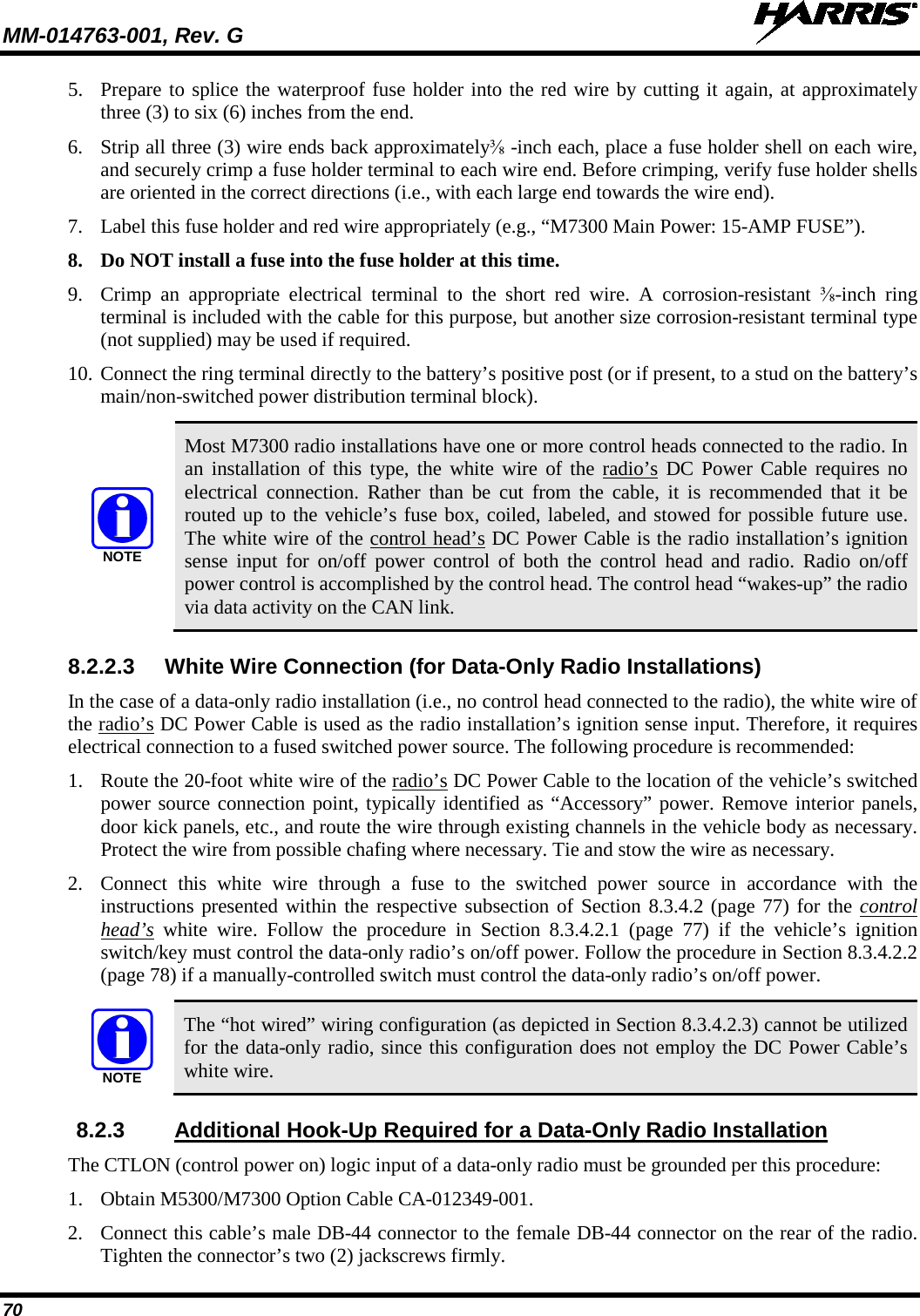
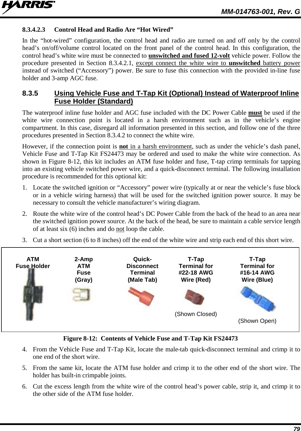
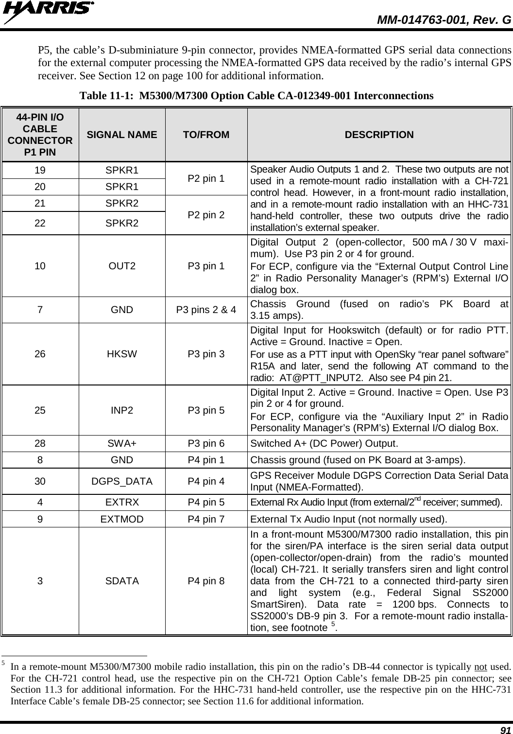
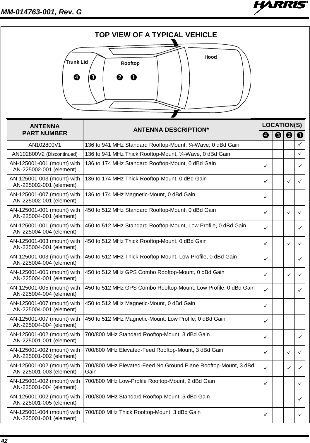
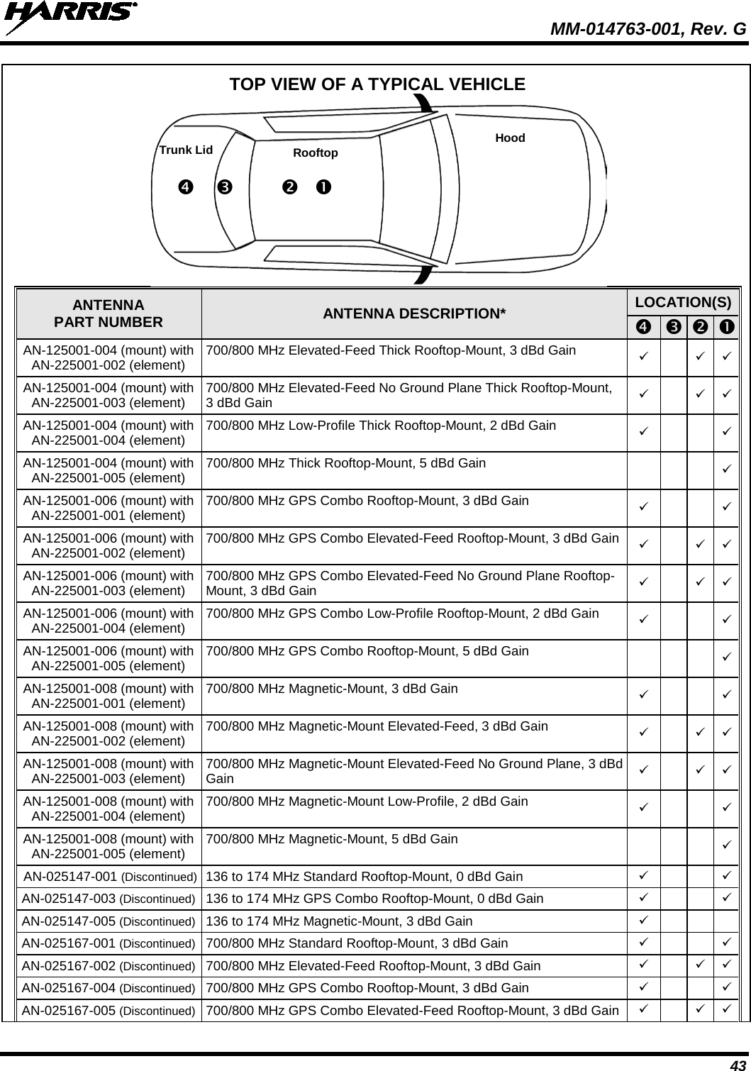
![MM-014763-001, Rev. G 13 Table 1-3: Recommended Minimum Safe Lateral Distance from a Transmitting Antenna Connected to a 700/800 MHz M7300 Mobile Radio [“M7300 (700/800 MHz)”] ANTENNA PART NUMBER ANTENNA DESCRIPTION RECOMMENDED MINIMUM LATERAL HUMAN BODY DISTANCE FROM TRANSMITTING ANTENNA CONTROLLED ENVIRONMENT UNCONTROLLED ENVIRONMENT AN102800V1 136 to 941 MHz, ¼-Wavelength**, Standard Rooftop-Mount; 0 dBd Gain 9.8 Inches (25 Centimeters) 21.7 Inches (55 Centimeters) AN102800V2 (Discontinued) 136 to 941 MHz, ¼-Wavelength**, Thick Rooftop-Mount; 0 dBd Gain AN-025167-001 (Discontinued) 700/800 MHz Standard Rooftop-Mount; 3 dBd Gain 11 Inches (28 Centimeters) 27.2 Inches (69 Centimeters) AN-025167-002 (Discontinued) 700/800 MHz Elevated-Feed Rooftop-Mount; 3 dBd Gain AN-025167-004 (Discontinued) 700/800 MHz GPS Combo Rooftop-Mount; 3 dBd Gain AN-025167-005 (Discontinued) 700/800 MHz GPS Combo Elevated-Feed Rooftop-Mount; 3 dBd Gain AN-025167-006 (Discontinued) 700/800 MHz Magnetic-Mount; 3 dBd Gain 11.4 Inches (29 Centimeters) 28.3 Inches (72 Centimeters) AN-025167-010 (Discontinued) 700/800 MHz Low-Profile Rooftop-Mount; 2 dBd Gain 11 Inches (28 Centimeters) 27.2 Inches (69 Centimeters) AN-025167-011 (Discontinued) 700/800 MHz GPS Combo Low-Profile Rooftop-Mount; 2 dBd Gain AN-025167-014 (Discontinued) 700/800 MHz Standard Rooftop-Mount; 5 dBd Gain 15.4 Inches (39 Centimeters) 34.3 Inches (87 Centimeters) AN-025167-015 (Discontinued) 700/800 MHz GPS Combo Rooftop-Mount; 5 dBd Gain STI-Co CCAS-SB-700 760 - 820 MHz Concealed Peal-and-Stick Internal-Mount; 0 dBi Gain 7.9 Inches (20 Centimeters) 19.7 Inches (50 Centimeters) * Driven elements of AN102800V1 and AN102800V2 must be trimmed to proper lengths in order to minimize antenna system VSWR. 1.3.1 Mobile Antennas The antenna(s) for the radio must be installed in accordance with Section 6 in this manual. Refer to Figure 6-1 on page 44 for applicable antenna part numbers. Installation guidelines presented in Section 6 are limited to metal-body motor vehicles or vehicles with appropriate ground planes. Use only approved/supplied antenna(s) or an approved replacement antenna. Unauthorized antennas, modifications, or attachments can cause the FCC RF exposure limits to be exceeded.](https://usermanual.wiki/HARRIS/TR-0062-E.Manual-1/User-Guide-1349711-Page-13.png)

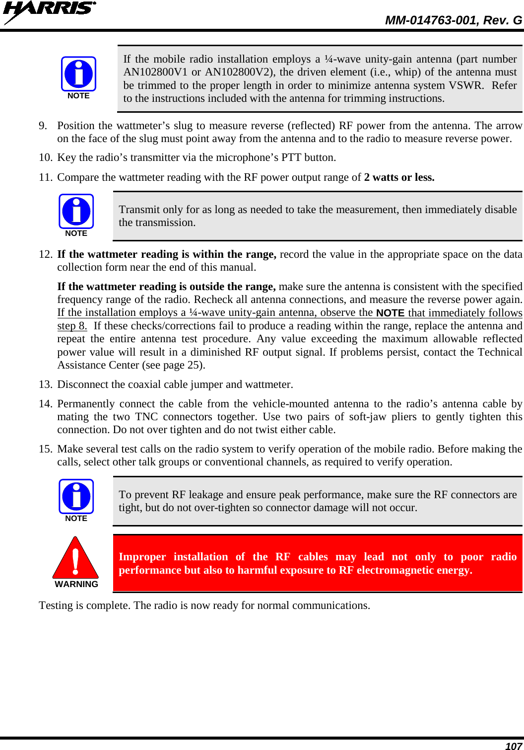
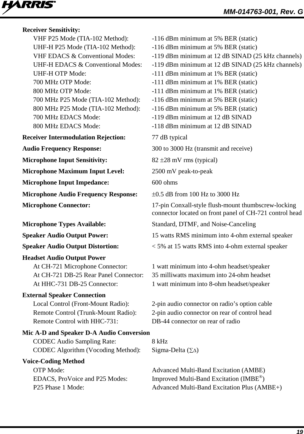
![MM-014763-001, Rev. G 18 HHC-731 Hand-Held Controller: 500 microamps maximum 2.2 TRANSCEIVER Frequency Ranges of VHF Radio: Receive: 136 to 174 MHz Transmit: 136 to 174 MHz Frequency Ranges of UHF-H Radio: Receive: 440 to 512 MHz Transmit: 440 to 512 MHz Frequency Ranges of 700 & 800 MHz Radio: Receive: 700 MHz Operation: 764 to 767 MHz, 769 to 775 MHz and 773 to 776 MHz (repeater and talk-around operations) [See footnote 2] 800 MHz Operation: 851 to 869 MHz (repeater and talk-around operations) Transmit: 700 MHz Talk-Around Operation: 764 to 767 MHz, 769 to 775 MHz and 773 to 776 MHz 700 MHz Repeater Operation: 794 to 797 MHz, 799 to 805 MHz and 803 to 806 MHz [See footnote 3] 800 MHz Talk-Around Operation: 851 to 869 MHz 800 MHz Repeater Operation: 806 to 824 MHz Transmit RF Output Power of VHF Radio: 136 to 174 MHz RF Channels: 10 to 50 watts (programmable range) Transmit RF Output Power of UHF-H Radio: 440 to 512 MHz RF Channels: 8 to 50 watts (programmable range) Transmit RF Output Power of 700 & 800 MHz Radio: 700 MHz Band RF Channels: 1.5 to 19 watts (programmable range) 800 MHz Band RF Channels: 5 to 35 watts (programmable range) Channel Spacing: 12.5 kHz or 25 kHz or 30 kHz (mode dependent) Voice and Data Communications Modes: Half-Duplex Frequency Stability: ±1.5 ppm with AFC disabled; ±0.5 ppm with AFC 2 764 to 767 MHz and 773 to 776 MHz per old FCC 700 MHz band plan. 769 to 775 MHz added August 30, 2007 by new FCC 700 MHz band plan. 3 764 to 767 MHz, 773 to 776 MHz, 794 to 797 MHz and 803 to 806 MHz per old FCC 700 MHz band plan. 769 to 775 MHz and 799 to 805 MHz added August 30, 2007 by new FCC 700 MHz band plan.](https://usermanual.wiki/HARRIS/TR-0062-E.Manual-1/User-Guide-1349711-Page-18.png)

![MM-014763-001, Rev. G 30 Table 4-5: Installation Kit MAMW-NZN7R for Remote-Mount M7300 Mobile Radio with CH-721 Control Head ITEM QTY. PART NUMBER DESCRIPTION ILLUSTRATION 6 1 CA-009562-030 Cable, CAN; 30 feet, Right-Angle-to-Straight Connectors. See Section 8.3.3 on page 74 7 1 LS102824V10 Speaker, External Mobile; 20-Watt (with 4.6-foot cable). See Section 9.2 on page 87. 8 1 MAMROS0034-NN006 Cable, Speaker; 6-Inch, Straight Connector. Section 9.2 on page 87. 9 2 FM-104859-001 Cap, Waterproof (For DB-9 serial port connectors on radio and control head.) [See footnote 4] 10 2 FM-104859-002 Cap, Waterproof (For DB-25 connectors on radio and control head.) [See footnote 4] The 20-amp fuse included with DC Power Cable CA-012365-001 should not be used in the M7300 mobile radio application of this cable. M7300 radio main power should be protected with the 15-amp fuse. Refer to Section 13 for additional information. 4 Earlier installation kits contained only one (1) each of FM-104859-001 and FM-104859-002. CAUTION (Continued)](https://usermanual.wiki/HARRIS/TR-0062-E.Manual-1/User-Guide-1349711-Page-30.png)

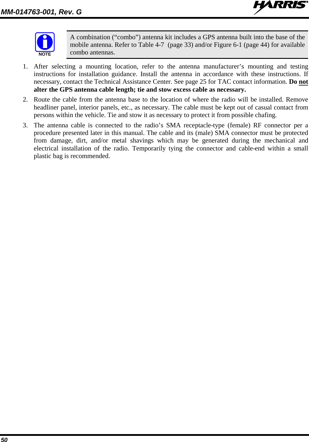
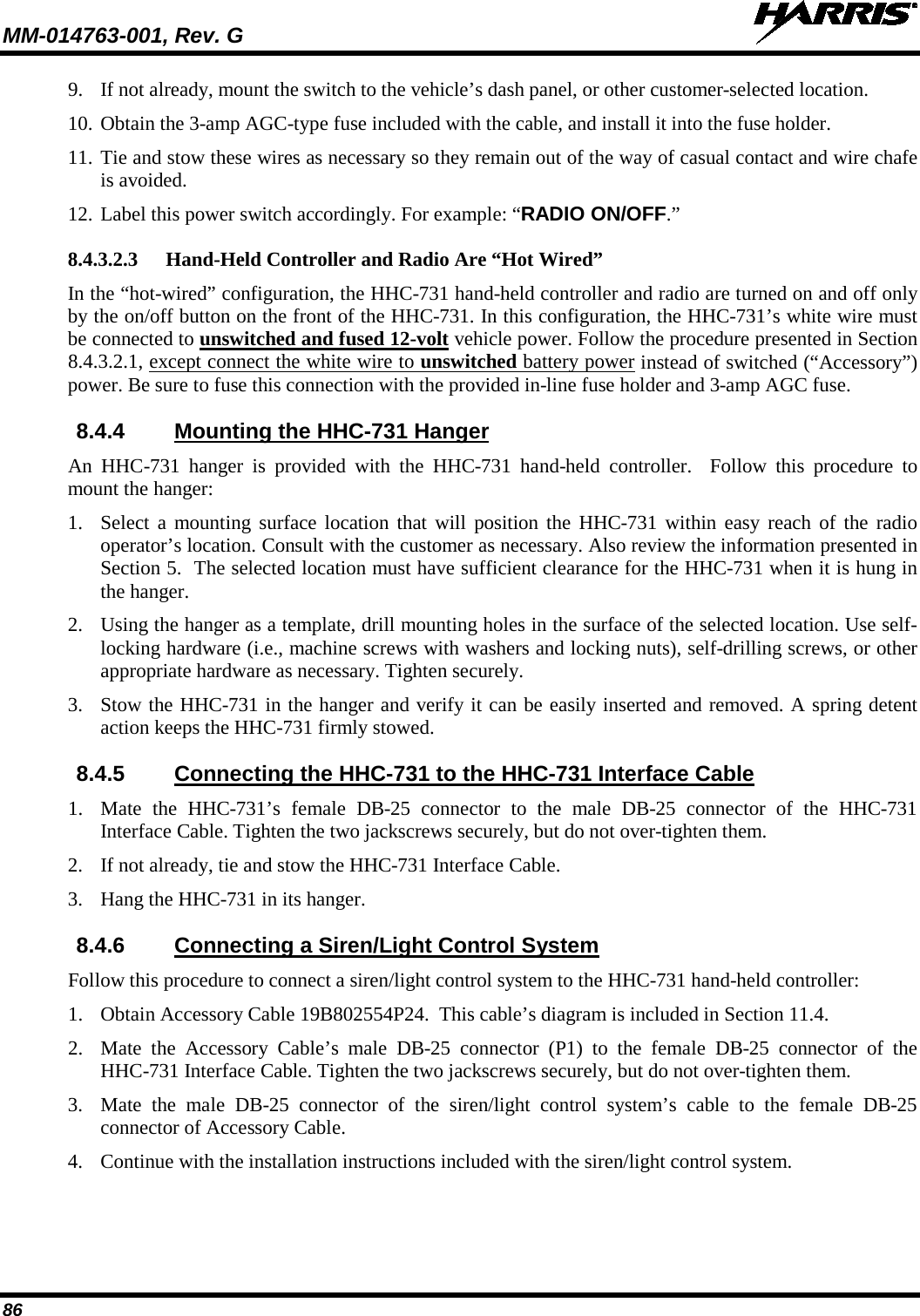
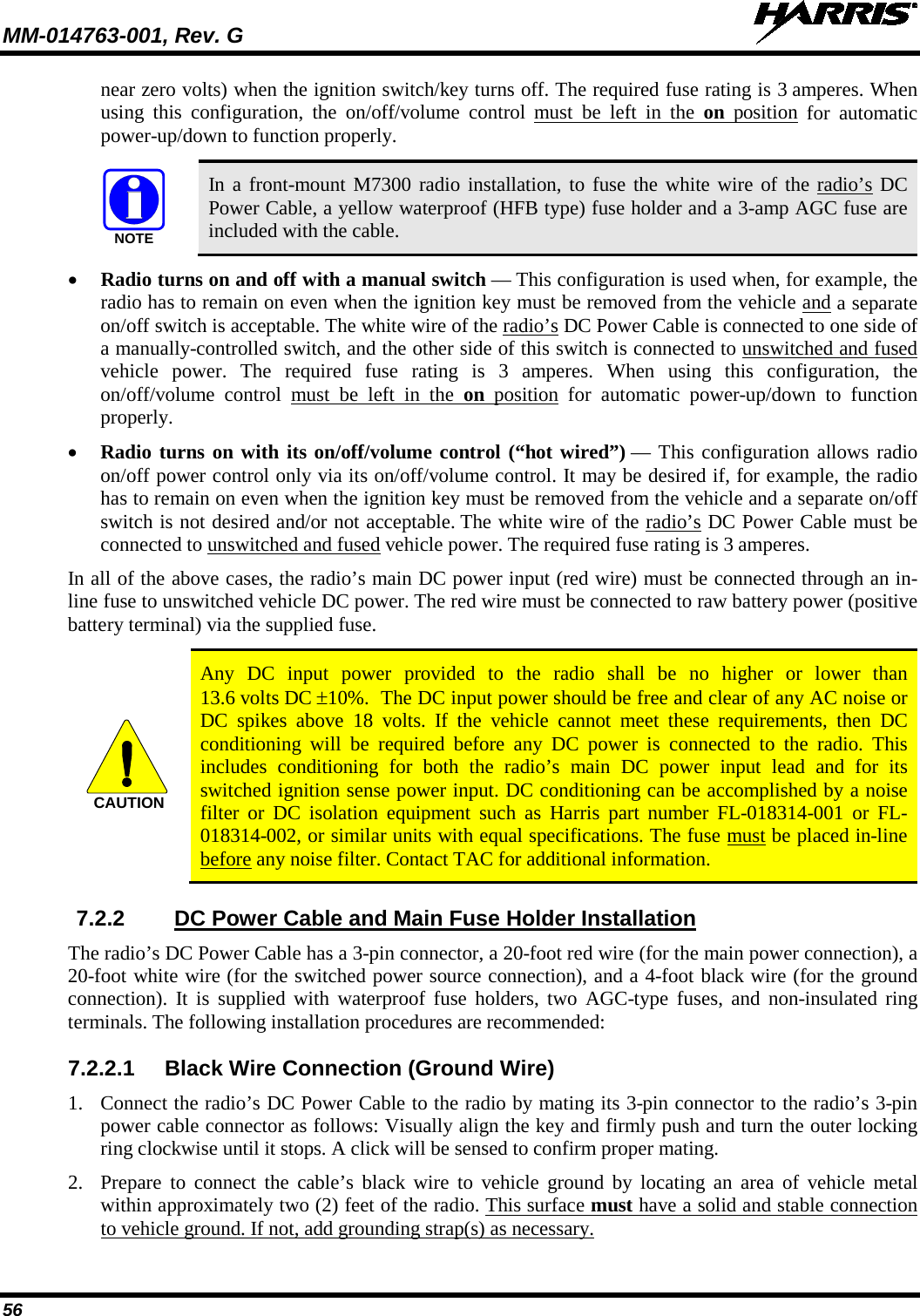
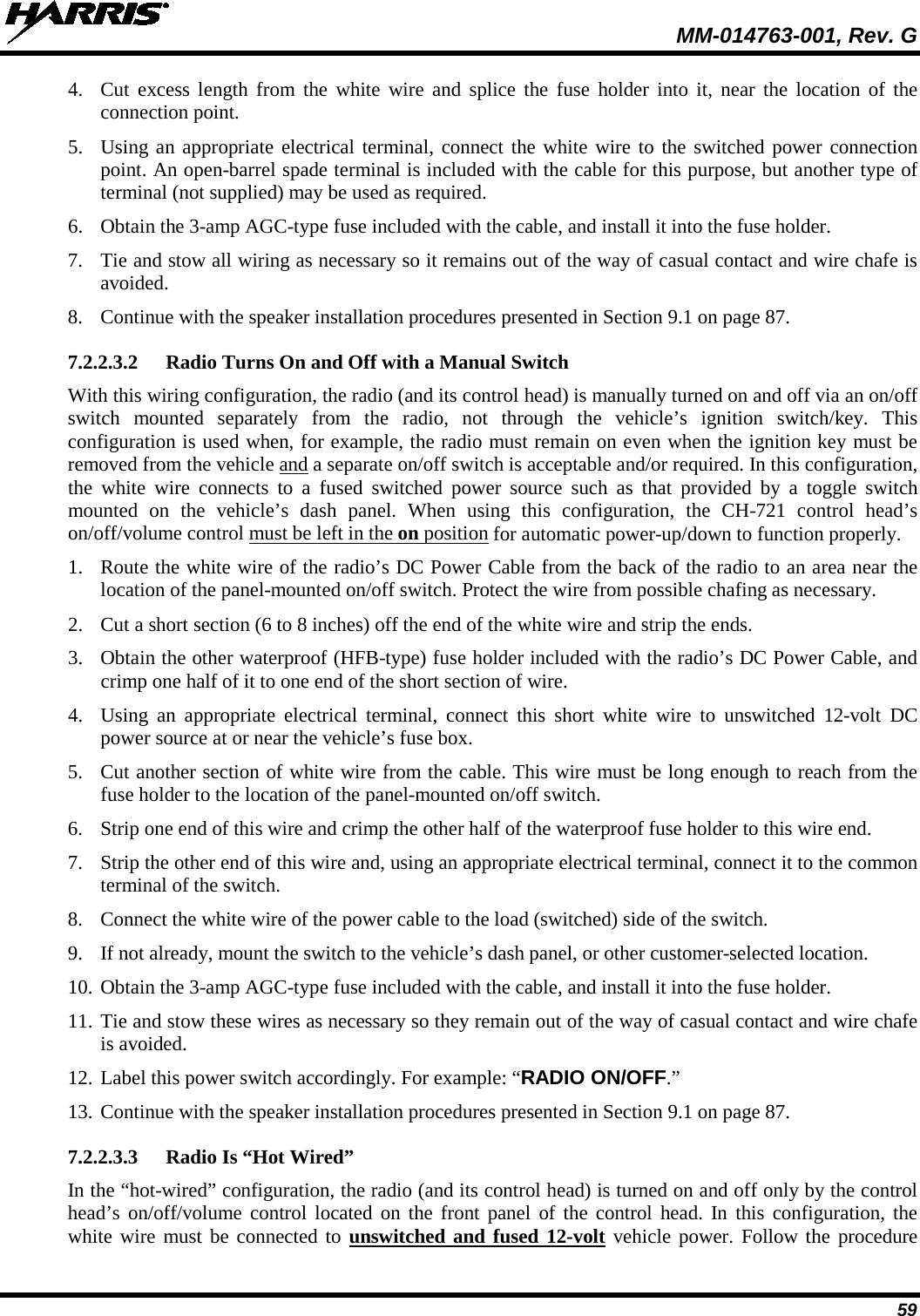
![MM-014763-001, Rev. G 54 TOP VIEW SIDE VIEW (Dimensions in Inches) FRONT/REAR VIEW (Dimensions in Inches) (Made From KBT0310B) Figure 7-3: Mounting Bracket FM101319V1 (Marked KTB0310) Dimensions [for Front-Mount M7300 Mobile Radio (Radio Not Shown)] 3. If the mounting surface is not flat (such as the top of a transmission hump), construct a suitable mounting wedge as necessary, and attach the wedge to the surface using an approved attachment method. Never mount the bracket directly to a non-flat surface. 4. On the mounting surface, mark the selected location for the bracket, and then remove the radio from the bracket. 5. Clean and remove any foreign material from the mounting surface. 6. Using the bracket as a template, and/or the dimensional information shown in Figure 8-3, mark and drill at least four (4) mounting holes into the mounting surface as required per the type of hardware used. 5.160.83 1.81 3.59 5.36 6.341.591.952.58(FM101319V1)B3.563.207.172.68Bracket-To-Vehicle Screw Holes (11 places) Bracket-To-Radio Screw Holes (10 places, 5 each side)](https://usermanual.wiki/HARRIS/TR-0062-E.Manual-1/User-Guide-1349711-Page-54.png)
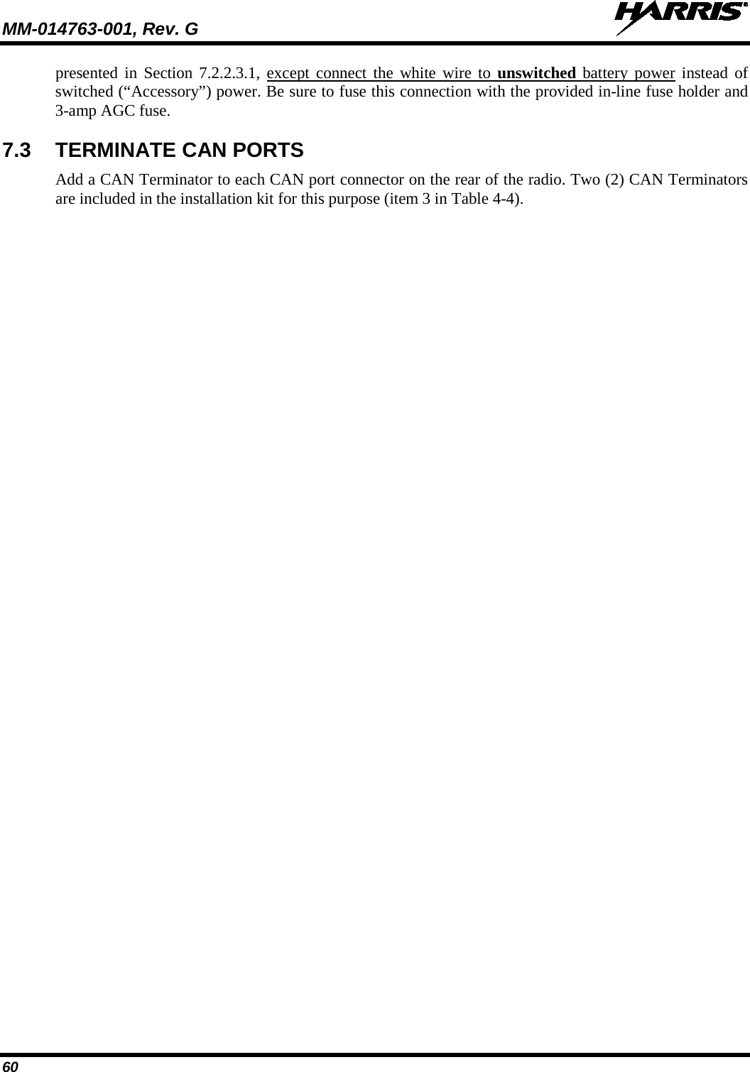
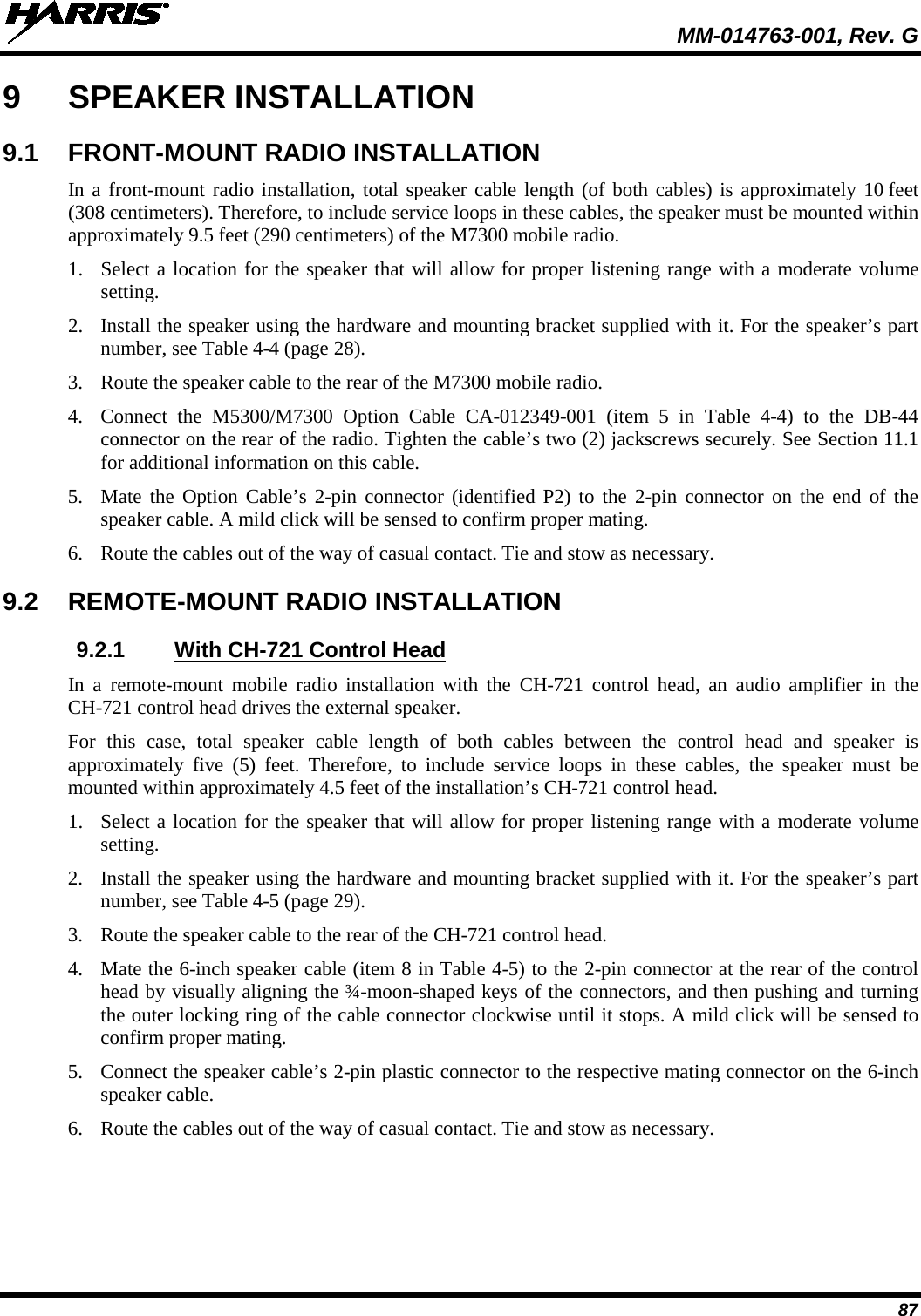
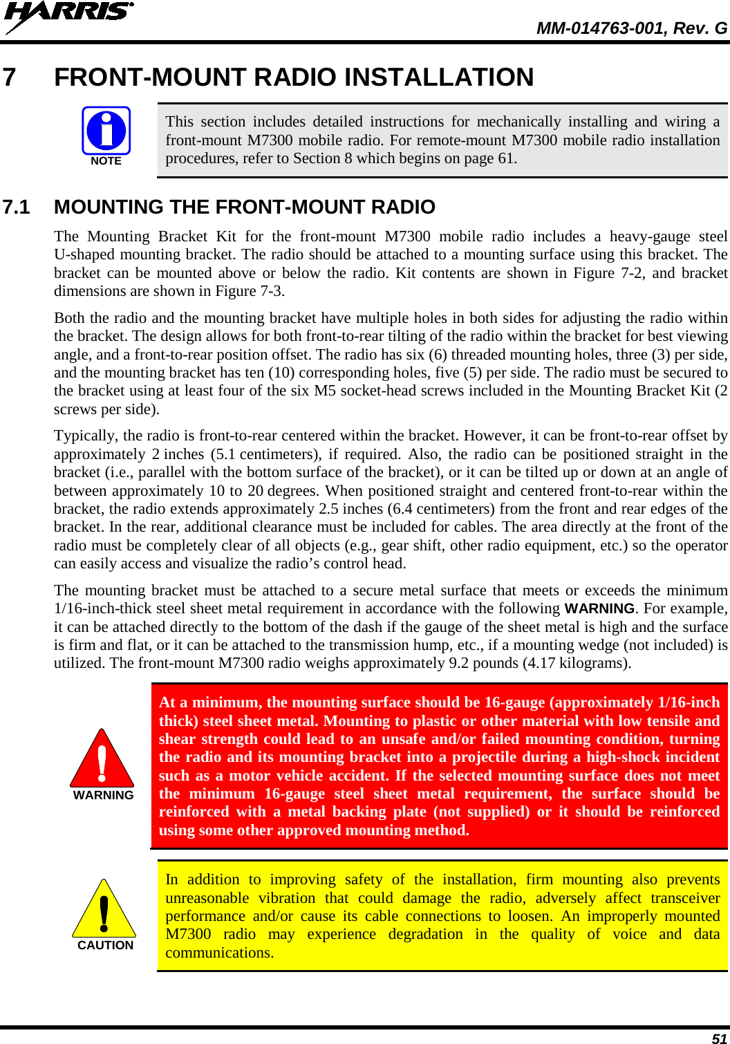
![MM-014763-001, Rev. G 64 3. If necessary, apply an approved paint or rust-inhibitor at the holes in the mounting surface. 4. Set the bracket back into place, and verify front-to-rear orientation. 5. Install and tighten the mounting screws/hardware. 6. Verify the bracket is firmly secured to the mounting surface. A secure mount prevents unreasonable vibration, which could damage the radio and/or cause its cable connections to loosen. TOP VIEW SIDE VIEW (Dimensions in Inches) FRONT VIEW (Dimensions in Inches) (Made From FM103111 Rev. B) Figure 8-3: Mounting Bracket FM103111V1 Dimensions [for Remote-Mount M7300 Mobile Radio (Radio Not Shown)] Bracket-To-Vehicle Screw Holes (4 places) Bracket-To-Radio Screw Holes (6 places, 3 each side) Rear of Bracket Front of Bracket](https://usermanual.wiki/HARRIS/TR-0062-E.Manual-1/User-Guide-1349711-Page-64.png)
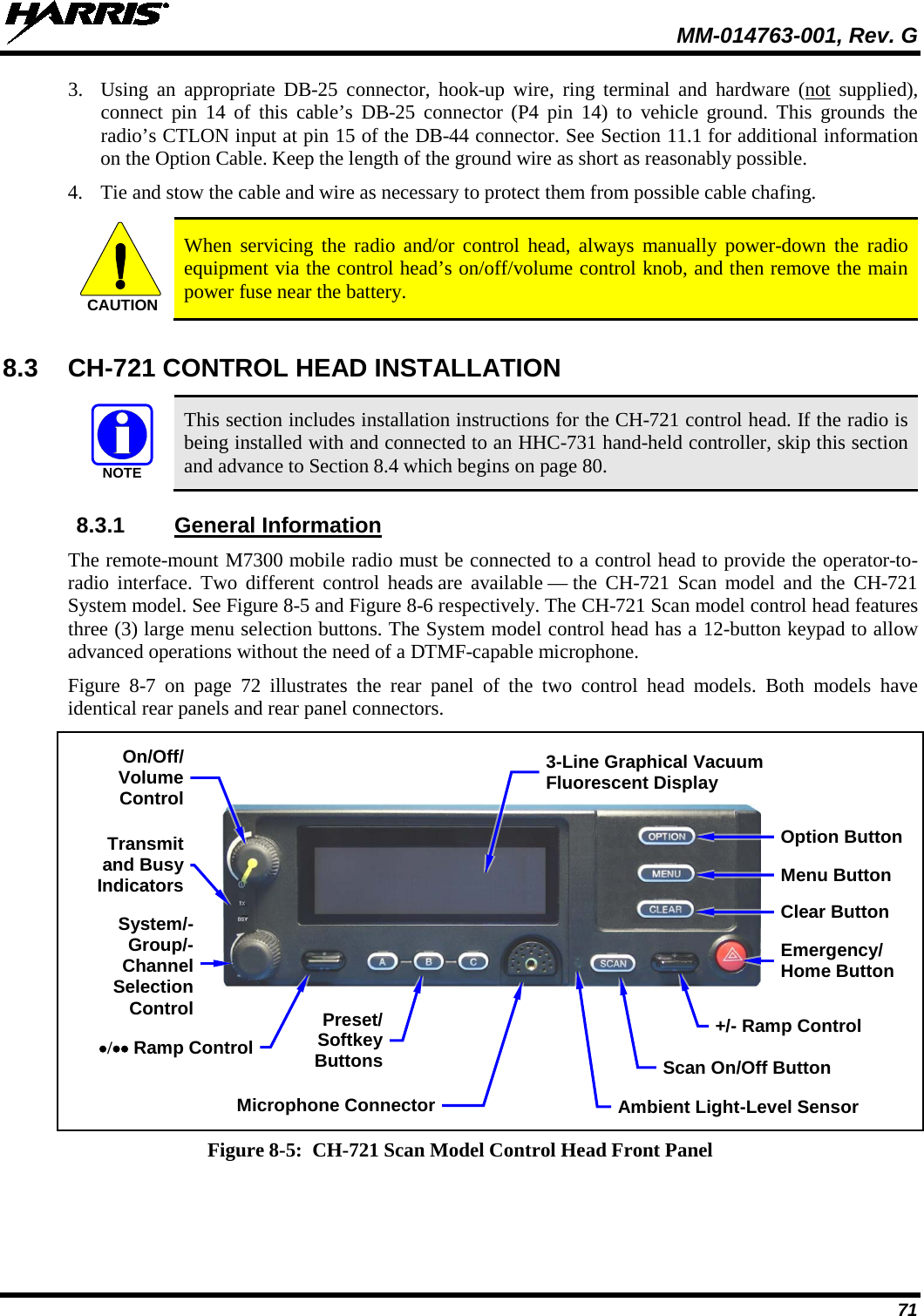
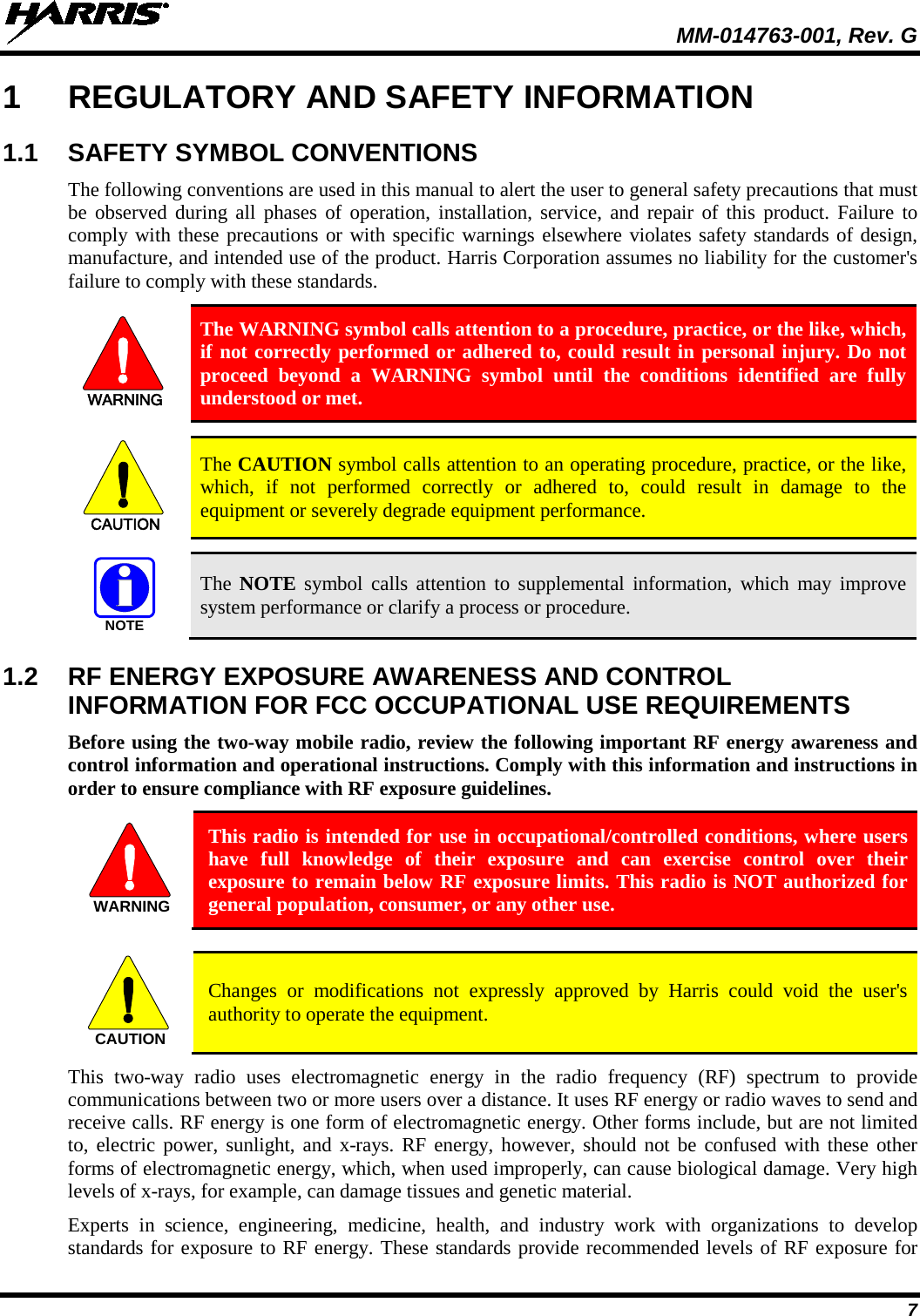
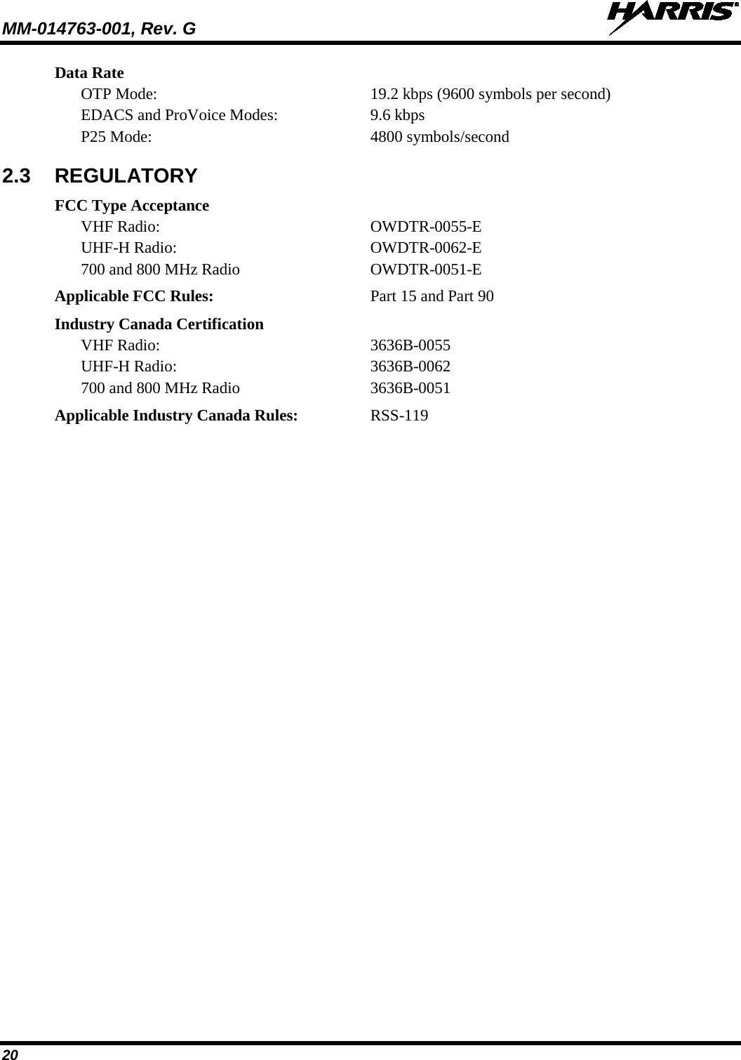
![MM-014763-001, Rev. G 66 Figure 8-4: Wiring Diagram for a Remote-Mount Radio Installation CH-721 SCAN MODELCONTROL HEADCU23218-0002(MAMW-NCP9E)CH-721 SYSTEM MODELCONTROL HEADCU23218-0004(MAMW-NCP9F)DTMFMICROPHONEMC-103334-040 ORMC-103334-041(INCLUDED WITHMAMW-NMC9C)STANDARD MICROPHONEMC-101616-040 ORMC-101616-041(INCLUDED WITHMAMW-NMC7Z)ORNOISE-CANCELINGMICROPHONEMC-103334-050 ORMC-103334-051(INCLUDED WITHMAMW-NMC9D)CH-721 MOUNTING BRACKET KITKT-008608[SUPPLIED WITH INSTALLATION KIT]• IF IGNITION SENSE ON/OFF FUNCTIONALITY IS REQUIRED, CONNECT WHITE WIRE OF CONTROL HEAD’S DC POWER CABLE TO A SWITCHED 13 VDC POWER SOURCE USING THE SUPPLIED FUSE AND FUSE HOLDER.• IF IGNITION SENSE ON/OFF FUNCTIONALITY IS NOT REQUIRED, CONNECT WHITE WIRE OF CONTROL HEAD’S DC POWER CABLE TO AN UNSWITCHED 13 VDC POWER SOURCE USING THE SUPPLIED FUSE AND FUSE HOLDER.WATERPROOF CAPFM-104859-001 (NOT SHOWN)FOR DB-9 SERIAL CONNECTOR[SUPPLIED WITH INSTALLATION KIT]WATERPROOF CAPFM-104859-002 (NOT SHOWN)FOR DB-25 ACCESSORY CONNECTOR[SUPPLIED WITH INSTALLATION KIT]REAR VIEW OF CONTROL HEADNEG POS3-AMP FUSE & FUSE HOLDER (HFB TYPE) REDRED RED5-AMPFUSE& FUSE HOLDER (HFB TYPE)3-AMP FUSE & FUSE HOLDER(HFB TYPE)15-AMPFUSE & FUSE HOLDER(HFB TYPE)REDWHITEREDRINGTERMINALSVEHICLEDC POWER DISTRI-BUTION BLOCK(E.G., “POWER ACCESS POINT”)VEHICLE BATTERY+-NOTE: BATTERY GROUND (-) CONNECTION NOT INDICATED.CAN TERMINATORCD-014027-001[SUPPLIED WITH INSTALLATION KIT]REDWHITEBLACK(SHORT AS POSSIBLE)RING TERMINAL (CONNECT TO VEHICLE CHASSIS GROUND)CAN CABLE CA-009562-030 (30 FEET LONG) [SUPPLIED WITH INSTALLATION KIT]SPEAKER CABLEMAMROS0034-NN006[SUPPLIED WITHINSTALLATION KIT]EXTERNAL SPEAKERLS102824V10[SUPPLIED WITHINSTALLATION KIT] WHITE WIRE OF RADIO’S DC POWER CABLE (LABELED AND COILED NEAR VEHICLE’S FUSE BOX)DC POWER CABLE CA-012616-001(SUPPLIED WITH INSTALLATION KIT)VEHICLE FUSE BOX, ETC.WHITE](https://usermanual.wiki/HARRIS/TR-0062-E.Manual-1/User-Guide-1349711-Page-66.png)
![MM-014763-001, Rev. G 67 GPS ANTENNA(OPTIONAL; SEE TEXT FOR SPECIFIC PART NUMBERS)DC POWER CABLECA-012365-001(SUPPLIED WITH INSTALLATION KIT)RING TERMINAL (CONNECT TO VEHICLE CHASSIS GROUND)BLACKBLACKREDWHITEM7300 MOBILE RADIOVHF RADIO = RU-144750-041;UHF-L RADIO = RU-144750-021;UHF-H RADIO = RU-144750-031;700 & 800 MHz RADIO = RU-144750-061REAR VIEWMOBILEANTENNA(OPTIONAL;SEE TEXT FOR SPECIFIC PART AND OPTION NUMBERS)MALE TNC RF CONNECTOR(SUPPLIED WITH ANTENNA)CAN TERMINATORCD-014027-001[SUPPLIED WITH INSTALLATION KIT] Figure 8-4: Wiring Diagram for a Remote-Mount Radio Installation (Cont.)](https://usermanual.wiki/HARRIS/TR-0062-E.Manual-1/User-Guide-1349711-Page-67.png)