HARRIS TR-0062-E M7300 440-512MHz 50W User Manual Manual 1
HARRIS CORPORATION M7300 440-512MHz 50W Manual 1
HARRIS >
Contents
- 1. Manual 1
- 2. Manual 2
Manual 1

Installation and Product Safety Manual
MM-014763-001
Rev. G, Sep/10
M7300 Series Mobile Radios
M7300 (700/800 MHz)
M7300 VHF 50-Watt
M7300 440 to 512 MHz 50-Watt
Front and Remote-Mount
Mobile Radios
Includes
CH-721 Scan and System
Control Heads
and
HHC-731 Hand-Held
Controller

MM-014763-001, Rev. G
2
MANUAL REVISION HISTORY
REV. DATE REASON FOR CHANGE
F Jun/10 Revised introduction, antenna part numbers and antenna installation procedures,
specifications, catalog and part number tables, and cable installation procedures. Added
HHC-731 hand-held controller.
G Sep/10 Revised antenna part numbers and the respective MPE distance data. Added 44
0 to
512 MHz (high-split UHF) radio.
Harris Corporation, Public Safety and Professional Communications (PSPC) Business, continually evaluates its technical
publications for completeness, technical accuracy, and organization. You can assist in this process by submitting your
comments and suggestions to the following:
Harris Corporation fax your comments to: 1-434-455-6851
PSPC Business or
Technical Publications e-mail us at: PSPC_TechPubs@harris.com
221 Jefferson Ridge Parkway
Lynchburg, VA 24501 ACKNOWLEDGEMENT
This device is made under license under one or more of the following US patents: 4,590,473; 4,636,791; 5,148,482;
5,185,796; 5,271,017; 5,377,229; 4,716,407; 4,972,460; 5,502,767; 5,146,497; 5,164,986; 5,185,795; 5,226,084; 5,247,579;
5,491,772; 5,517,511; 5,630,011; 5,649,050; 5,701,390; 5,715,365; 5,754,974; 5,826,222; 5,870,405; 6,161,089; and
6,199,037 B1. DVSI claims certain rights, including patent rights under aforementioned U.S. patents, and under other U.S.
and foreign patents and patents pending. Any use of this software or technology requires a separate written license from
DVSI. CREDITS
Harris, assuredcommunications, OpenSky and EDACS are registered trademarks of and ProVoice is a trademark of Harris
Corporation.
AMBE is a registered trademark and IMBE, AMBE+, and AMBE+2 are trademarks of Digital Voice Systems, Inc. Bird is a
registered trademark of Bird Electronic Corporation. Microsoft and Windows are registered trademarks of Microsoft
Corporation. SmartSiren is a registered trademark of Federal Signal Corporation.
All other brand and product names are trademarks, registered trademarks, or service marks of their respective holders.
NOTICE!
The material contained herein is subject to U.S. export approval. No export or re-export is permitted without written
approval from the U.S. Government. Rated: EAR99 in accordance with U.S. Dept. of Commence regulations 15CFR774,
Export Administration Regulations.
Information and descriptions contained herein are the property of Harris Corporation. Such information and descriptions may
not be copied or reproduced by any means, or disseminated or distributed without the express prior written permission of
Harris Corporation, PSPC Business, 221 Jefferson Ridge Parkway, Lynchburg, VA 24501.
The voice coding technology embodied in this product is protected by intellectual property rights including patent rights,
copyrights, and trade secrets of Digital Voice Systems, Inc. The user of this technology is explicitly prohibited from
attempting to decompile, reverse engineer, or disassemble the Object Code, or in any other way convert the Object Code into
human-readable form.
Repairs to this equipment should be made only by an authorized service technician or facility designated by the supplier. Any
repairs, alterations or substitutions of recommended parts made by the user to this equipment not approved by the
manufacturer could void the user's authority to operate the equipment in addition to the manufacturer's warranty.
This product conforms to the European Union WEEE Directive 2002/96/EC. Do not dispose of this product in a
public landfill. Take it to a recycling center at the end of its life.
This manual is published by Harris Corporation without any warranty. Improvements and changes to this manual necessitated by typographical errors,
inaccuracies of current information, or improvements to programs and/or equipment, may be made by Harris Corporation
at any time and without notice.
Such changes will be incorporated into new editions of this manual. No part of this manual may be reproduced or transmitted in any
form or by any means,
electronic or mechanical, including photocopying and recording, for any purpose, without the express written permission of
Harris Corporation.
Copyright © 2008, 2009, 2010, Harris Corporation

MM-014763-001, Rev. G
3
TABLE OF CONTENTS
Section Page
1 REGULATORY AND SAFETY INFORMATION .................................................................................... 7
1.1 SAFETY SYMBOL CONVENTIONS ................................................................................................. 7
1.2 RF ENERGY EXPOSURE AWARENESS AND CONTROL INFORMATION FOR FCC
OCCUPATIONAL USE REQUIREMENTS........................................................................................ 7
1.2.1 Federal Communications Commission Regulations ............................................................... 8
1.3 COMPLIANCE WITH RF EXPOSURE STANDARDS ...................................................................... 8
1.3.1 Mobile Antennas .................................................................................................................. 13
1.3.2 Approved Accessories .......................................................................................................... 14
1.3.3 Contact Information .............................................................................................................. 14
1.4 OCCUPATIONAL SAFETY GUIDELINES AND SAFETY TRAINING INFORMATION ........... 14
1.5 COMMON HAZARDS ...................................................................................................................... 14
1.6 SAFE DRIVING RECOMMENDATIONS ........................................................................................ 15
1.7 OPERATING RULES AND REGULATIONS .................................................................................. 16
1.8 OPERATING TIPS ............................................................................................................................. 16
2 SPECIFICATIONS ..................................................................................................................................... 17
2.1 GENERAL .......................................................................................................................................... 17
2.2 TRANSCEIVER ................................................................................................................................. 18
2.3 REGULATORY ................................................................................................................................. 20
3 INTRODUCTION ....................................................................................................................................... 21
3.1 GENERAL DESCRIPTION ............................................................................................................... 21
3.2 RELATED PUBLICATIONS ............................................................................................................. 24
3.3 REPLACEMENT PARTS .................................................................................................................. 24
3.4 TECHNICAL ASSISTANCE ............................................................................................................. 25
4 UNPACKING AND CHECKING THE EQUIPMENT ........................................................................... 26
4.1 MATERIALS ..................................................................................................................................... 26
4.2 MATERIAL INSPECTION ................................................................................................................ 27
5 PLANNING THE INSTALLATION ......................................................................................................... 37
5.1 GENERAL INFORMATION ............................................................................................................. 37
5.2 TOOLS REQUIRED .......................................................................................................................... 37
5.3 LOCATING COMPONENTS ............................................................................................................ 40
6 ANTENNA INSTALLATION .................................................................................................................... 41
6.1 ANTENNA MOUNTING LOCATIONS ........................................................................................... 41
6.1.1 Direct Center or Center-Rear of Rooftop ............................................................................. 41
6.1.2 Center of Trunk Lid .............................................................................................................. 41
6.1.3 Rear Deck Lid for Stand-Alone GPS Receive Antenna ....................................................... 41
6.2 ANTENNA INSTALLATION PROCEDURES ................................................................................. 44
6.2.1 Installing NMO Antenna Mounts AN-125001-001, -002, -003 and -004 ............................ 44
6.2.2 Installing NMO Magnetic Antenna Mounts AN-125001-007 and AN-125001-008 ............ 47
6.2.3 Installing All Other Antenna Mounts ................................................................................... 47
6.2.4 Attaching NMO Antenna Elements ...................................................................................... 47
6.2.5 Installing the Coax Cable and TNC RF Connector .............................................................. 48
6.2.6 Install GPS Antenna (Required Only if Radio has GPS Receiver Option)........................... 49
7 FRONT-MOUNT RADIO INSTALLATION ........................................................................................... 51
7.1 MOUNTING THE FRONT-MOUNT RADIO ................................................................................... 51
7.1.1 Mounting Bracket Installation .............................................................................................. 53
7.1.2 Inserting the Radio into the Mounting Bracket .................................................................... 55
7.2
FRONT-MOUNT
RADIO’S
DC
POWER
INSTALLATION ............................................................ 55

MM-014763-001, Rev. G
4
TABLE OF CONTENTS
Section Page
7.2.1 Overview of On/Off Power Wiring Configurations .............................................................. 55
7.2.2 DC Power Cable and Main Fuse Holder Installation ............................................................ 56
7.3 TERMINATE CAN PORTS ............................................................................................................... 60
8 REMOTE-MOUNT RADIO INSTALLATION ....................................................................................... 61
8.1 MOUNTING THE REMOTE-MOUNT RADIO ................................................................................ 61
8.1.1 Mounting Bracket Installation .............................................................................................. 63
8.1.2 Inserting the Radio into the Mounting Bracket ..................................................................... 65
8.2 REMOTE-MOUNT RADIO’S DC POWER INSTALLATION ......................................................... 65
8.2.1 Overview of On/Off Power Wiring Configurations .............................................................. 65
8.2.2 DC Power Cable and Main Fuse Holder Installation ............................................................ 68
8.2.3 Additional Hook-Up Required for a Data-Only Radio Installation ...................................... 70
8.3 CH-721 CONTROL HEAD INSTALLATION ................................................................................... 71
8.3.1 General Information .............................................................................................................. 71
8.3.2 Control Head Mechanical Installation .................................................................................. 73
8.3.3 Control Head-to-Radio CAN Cable Connections ................................................................. 74
8.3.4 Control Head Power Cable Installation ................................................................................ 76
8.3.5 Using Vehicle Fuse and T-Tap Kit (Optional) Instead of Waterproof Inline Fuse
Holder (Standard) ................................................................................................................. 79
8.4 HHC-731 HAND-HELD CONTROLLER INSTALLATION ............................................................ 80
8.4.1 Mounting the HHC-731 Interface Cable and Bracket ........................................................... 81
8.4.2 Connecting CAN Link .......................................................................................................... 82
8.4.3 Connecting DC Power .......................................................................................................... 83
8.4.4 Mounting the HHC-731 Hanger ........................................................................................... 86
8.4.5 Connecting the HHC-731 to the HHC-731 Interface Cable ................................................. 86
8.4.6 Connecting a Siren/Light Control System ............................................................................ 86
9 SPEAKER INSTALLATION ..................................................................................................................... 87
9.1 FRONT-MOUNT RADIO INSTALLATION..................................................................................... 87
9.2 REMOTE-MOUNT RADIO INSTALLATION ................................................................................. 87
9.2.1 With CH-721 Control Head .................................................................................................. 87
9.2.2 With HHC-731 Hand-Held Controller .................................................................................. 88
10 MICROPHONE ATTACHMENT ............................................................................................................. 89
11 OPTIONAL CABLES ................................................................................................................................. 90
11.1 M5300/M7300 OPTION CABLE CA-012349-001 ............................................................................ 90
11.2 SERIAL PROGRAMMING CABLE CA-013671-020 ....................................................................... 94
11.3 CH-721 OPTION CABLE CA-011854-001 ........................................................................................ 95
11.4 ACCESSORY CABLE 19B802554P24 .............................................................................................. 96
11.5 CH-721 SERIAL PROGRAMMING CABLE CA-104861 ................................................................. 97
11.6 HHC-731 INTERFACE CABLE CA-018399-001.............................................................................. 98
11.7 SPEAKER-ONLY OPTION CABLE CA-012349-007 ...................................................................... 99
12 GPS NMEA-FORMATTED SERIAL DATA CONNECTION ............................................................. 100
13 INITIAL POWER-UP TEST .................................................................................................................... 101
14 PERFORMANCE TESTS ........................................................................................................................ 102
14.1 CHANGING OPERATING MODE FOR TESTS............................................................................. 102
14.1.1 Changing from OpenSky to Conventional .......................................................................... 102
14.1.2 Changing from Conventional to OpenSky .......................................................................... 103
14.2 REQUIRED TEST EQUIPMENT .................................................................................................... 104
14.3
TRANSMITTING
INTO
A
DUMMY
LOAD .................................................................................. 104

MM-014763-001, Rev. G
5
TABLE OF CONTENTS
Section Page
14.4 TRANSMITTING
INTO
THE
MOBILE
ANTENNA ...................................................................... 106
14.5 TEST PERFORMANCE DATA FORM ........................................................................................... 109
15 COMPLETE THE INSTALLATION ..................................................................................................... 110
16 WARRANTY REGISTRATION ............................................................................................................. 110
17 WARRANTY ............................................................................................................................................. 111
LIST OF FIGURES
Page
Figure 5-1: Typical Front-Mount Mobile Radio Installation in a Standard Passenger Vehicle .......................... 38
Figure 5-2: Typical Remote-Mount Mobile Radio Installation in a Standard Passenger Vehicle ....................... 38
Figure 5-3: M7300 Front-Mount and Remote-Mount Mobile Radios — Front and Rear Views ........................ 39
Figure 6-1: Recommended Antenna Mounting Locations with Antenna Part Numbers ..................................... 44
Figure 6-2: Installing a Standard ¾-Inch NMO Antenna Mount (e.g., AN-125001-001 or AN-125001-002) ... 46
Figure 6-3: Installing a Thick-Roof NMO Antenna Mount (e.g., AN-125001-003 or AN-125001-004) ........... 47
Figure 6-4: Crimping Instructions for TNC RF Connector ................................................................................. 49
Figure 7-1: Front-Mount M7300 Radio Dimensions ........................................................................................... 52
Figure 7-2: Front-Mount Mounting Bracket Kit KT101533V1 .......................................................................... 53
Figure 7-3: Mounting Bracket FM101319V1 (Marked KTB0310) Dimensions [for Front-Mount M7300
Mobile Radio (Radio Not Shown)] .............................................................................................. 54
Figure 8-1: Remote-Mount M7300 Radio Dimensions ....................................................................................... 62
Figure 8-2: Remote-Mount Mounting Bracket Kit KT23117 ............................................................................. 63
Figure 8-3: Mounting Bracket FM103111V1 Dimensions [for Remote-Mount M7300 Mobile Radio
(Radio Not Shown)] ..................................................................................................................... 64
Figure 8-4: Wiring Diagram for a Remote-Mount Radio Installation ................................................................. 66
Figure 8-5: CH-721 Scan Model Control Head Front Panel ............................................................................... 71
Figure 8-6: CH-721 System Model Control Head Front Panel ........................................................................... 72
Figure 8-7: CH-721 Rear Panel (both control head models) ............................................................................... 72
Figure 8-8: Standard U-Shaped Control Head Mounting Bracket (Kit Part Number KT-008608) ..................... 73
Figure 8-9: Optional Control Head Mounting Pedestal (Part Number MACDOS0012) ..................................... 73
Figure 8-10: CAN Link Connections for a Single Control Head Installation ..................................................... 75
Figure 8-11: Typical CAN Link Connections for a Multi-Control Head Installation ......................................... 75
Figure 8-12: Contents of Vehicle Fuse and T-Tap Kit FS24473 ......................................................................... 79
Figure 8-13: Attaching T-Tap Terminals to a Switched Power Wire .................................................................. 80
Figure 8-14: HHC-731 Hand-Held Controller Front View ................................................................................. 81
Figure 8-15: HHC-731 Interface Cable Mounting Bracket Kit KT-018752-001 ................................................ 81
Figure 8-16: HHC-731 Interface Cable Mounting Bracket-to-Cable Positioning ............................................... 82
Figure 8-17: M7300-to-HHC-731 CAN Link Connections ................................................................................ 83
Figure 10-1: Attaching the Microphone to the CH-721Control Head ................................................................. 89
Figure 11-1: M5300/M7300 Option Cable CA-012349-001 ............................................................................... 90
Figure 11-2: Serial Programming Cable CA-013671-020 ................................................................................... 94
Figure 11-3: CH-721 Option Cable CA-011854-001 .......................................................................................... 95
Figure 11-4: Accessory Cable 19B802554P24.................................................................................................... 96
Figure 11-5: Programming Cable CA-104861 .................................................................................................... 97
Figure 11-6: HHC-731 Interface Cable CA-018399-001 .................................................................................... 98
Figure 11-7: Speaker-Only Option Cable CA-012349-007 ................................................................................. 99
Figure 14-1: Wattmeter Connections for Antenna System Tests ...................................................................... 105
(Continued)

MM-014763-001, Rev. G
6
LIST OF TABLES
Page
Table 1-1: Recommended Minimum Safe Lateral Distance from Transmitting Antenna Connected to a
VHF M7300 Mobile Radio (“M7300 VHF 50-Watt”) .................................................................. 9
Table 1-2: Recommended Minimum Safe Lateral Distance from a Transmitting Antenna Connected to a
High-Split UHF M7300 Mobile Radio (“M7300 440 to 512 MHz 50-Watt”) ............................ 10
Table 1-3: Recommended Minimum Safe Lateral Distance from a Transmitting Antenna Connected to a
700/800 MHz M7300 Mobile Radio [“M7300 (700/800 MHz)”] ............................................... 11
Table 3-1: Radio Systems/Standards Supported by the M7300 Mobile Radio .................................................... 21
Table 4-1: M7300 Mobile Radio Catalog and Part Numbers .............................................................................. 26
Table 4-2: CH-721 Control Head Catalog and Part Numbers ............................................................................. 26
Table 4-3: AES and DES Encryption Catalog Numbers for M7300 Mobile Radios ........................................... 27
Table 4-4: Installation Kit MAMW-NZN6W for Front-Mount M7300 Mobile Radio ....................................... 28
Table 4-5: Installation Kit MAMW-NZN7R for Remote-Mount M7300 Mobile Radio with CH-721
Control Head ................................................................................................................................ 29
Table 4-6: HHC-731 Hand-Held Controller and Installation Components — Installation Kit MAMW-
NCP9P ......................................................................................................................................... 31
Table 4-7: Additional Options and Accessories for M7300 Mobile Radios ........................................................ 33
Table 4-8: Additional Options and Accessories for CH-721 Control Heads ....................................................... 36
Table 11-1: M5300/M7300 Option Cable CA-012349-001 Interconnections ..................................................... 91
Table 14-1: Required Test Equipment ............................................................................................................... 104
MM-014763-001, Rev. G
7
1 REGULATORY AND SAFETY INFORMATION
1.1 SAFETY SYMBOL CONVENTIONS
The following conventions are used in this manual to alert the user to general safety precautions that must
be observed during all phases of operation, installation, service, and repair of this product. Failure to
comply with these precautions or with specific warnings elsewhere violates safety standards of design,
manufacture, and intended use of the product. Harris Corporation assumes no liability for the customer's
failure to comply with these standards.
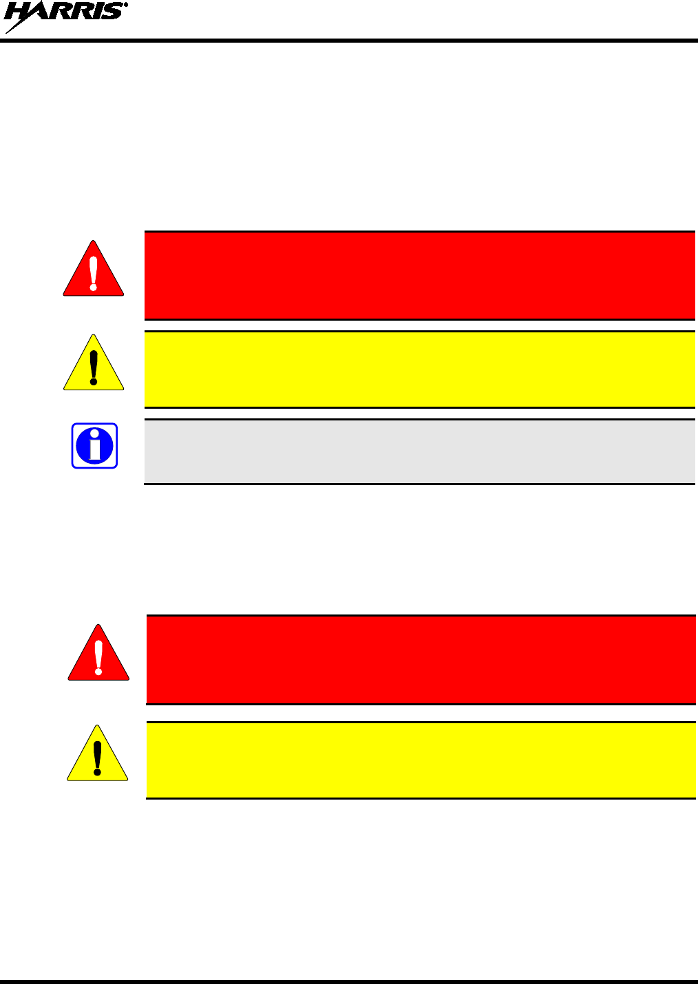
WARNING
The WARNING symbol calls attention to a procedure, practice, or the like, which,
if not correctly performed or adhered to, could result in personal injury. Do not
proceed beyond a WARNING symbol until the conditions identified are fully
understood or met.
CAUTION
The CAUTION symbol calls attention to an operating procedure, practice, or the like,
which, if not performed correctly or adhered to, could result in damage to the
equipment or severely degrade equipment performance.
NOTE
The NOTE symbol calls attention to supplemental information, which may improve
system performance or clarify a process or procedure.
1.2 RF ENERGY EXPOSURE AWARENESS AND CONTROL
INFORMATION FOR FCC OCCUPATIONAL USE REQUIREMENTS
Before using the two-way mobile radio, review the following important RF energy awareness and
control information and operational instructions. Comply with this information and instructions in
order to ensure compliance with RF exposure guidelines.
This radio is intended for use in occupational/controlled conditions, where users
have full knowledge of their exposure and can exercise control over their
exposure to remain below RF exposure limits. This radio is NOT authorized for
general population, consumer, or any other use.
Changes or modifications not expressly approved by Harris
could void the user's
authority to operate the equipment.
This two-way radio uses electromagnetic energy in the radio frequency (RF) spectrum to provide
communications between two or more users over a distance. It uses RF energy or radio waves to send and
receive calls. RF energy is one form of electromagnetic energy. Other forms include, but are not limited
to, electric power, sunlight, and x-rays. RF energy, however, should not be confused with these other
forms of electromagnetic energy, which, when used improperly, can cause biological damage. Very high
levels of x-rays, for example, can damage tissues and genetic material.
Experts in science, engineering, medicine, health, and industry work with organizations to develop
standards for exposure to RF energy. These standards provide recommended levels of RF exposure for
WARNING
CAUTION
MM-014763-001, Rev. G
8
both workers and the general public. These recommended RF exposure levels include substantial margins
of protection. All two-way radios marketed in North America are designed, manufactured, and tested to
ensure they meet government-established RF exposure levels. In addition, manufacturers also recommend
specific operating instructions to users of two-way radios. These instructions are important because they
inform users about RF energy exposure and provide simple procedures on how to control it. Refer to the
following websites for more information on what RF energy exposure is and how to control exposure to
assure compliance with established RF exposure limits:
http://www.fcc.gov/oet/rfsafety/rf-faqs.html
http://www.osha.gov./SLTC/radiofrequencyradiation/index.html
1.2.1 Federal Communications Commission Regulations
Before it was marketed in the United States, the M7300 two-way mobile radio was tested to ensure
compliance with FCC RF energy exposure limits for two-way mobile radios. When two-way radios are
used as a consequence of employment, the FCC requires users to be fully aware of and able to control
their exposure to meet occupational requirements. Exposure awareness can be facilitated by the use of a
label directing users to specific user awareness information. The radio has an RF exposure product label.
Also, this Installation and Product Safety Manual and the applicable Operator’s Manual include
information and operating instructions required to control RF exposure and to satisfy compliance
requirements.
1.3 COMPLIANCE WITH RF EXPOSURE STANDARDS
The M7300 two-way mobile radio is designed and tested to comply with a number of national and
international standards and guidelines regarding human exposure to RF electromagnetic energy. This
radio complies with the IEEE and ICNIRP exposure limits for occupational/controlled RF exposure
environment at duty-cycle times of up to 50% (50% transmit, 50% receive), and it is authorized by the
FCC for occupational use. In terms of measuring RF energy for compliance with the FCC exposure
guidelines, the radio’s antenna radiates measurable RF energy only while it is transmitting (talking), not
when it is receiving (listening), or in a standby mode.
The M7300 two-way mobile radio complies with the following RF energy exposure standards and
guidelines:
• United States Federal Communications Commission (FCC), Code of Federal Regulations; 47 CFR
§ 2 sub-part J.
• American National Standards Institute (ANSI)/Institute of Electrical and Electronic Engineers (IEEE)
C95.1-2005.
• Institute of Electrical and Electronic Engineers (IEEE) C95.1-2005.
• IC Standard RSS-102, Issue 2, 2005: Spectrum Management and Telecommunications Radio
Standards Specification. Radiofrequency Exposure Compliance of Radiocommunication Apparatus
(All Frequency Bands).
Table 1-1 through Table 1-3 list the recommended minimum safe lateral distances for a
controlled environment and for unaware bystanders in an uncontrolled environment,
from transmitting antennas (i.e., monopoles over a ground plane, or dipoles) at rated
radio power for mobile radios installed in a vehicle. Transmit only when unaware
bystanders are at least the uncontrolled recommended minimum safe lateral distance
away from the transmitting antenna.
CAUTION

MM-014763-001, Rev. G
9
Based on the highest radiated RF power and the highest antenna gain in antennas to be used with M7300,
the distances listed in Table 1-1 through Table 1-3 are considered as safe distances for controlled and
uncontrolled environments with the M7300 mobile radio transmitting at a maximum 50% duty cycle:
Table 1-1: Recommended Minimum Safe Lateral Distance from Transmitting Antenna
Connected to a VHF M7300 Mobile Radio (“M7300 VHF 50-Watt”)
ANTENNA
PART NUMBER ANTENNA DESCRIPTION
RECOMMENDED MINIMUM LATERAL HUMAN BODY
DISTANCE FROM TRANSMITTING ANTENNA
CONTROLLED
ENVIRONMENT UNCONTROLLED
ENVIRONMENT
AN102800V1 136 to 941 MHz, ¼-Wavelength*,
Standard Rooftop-Mount;
0 dBd Gain
24.8 Inches
(63 Centimeters) 55.1 Inches
(140 Centimeters)
AN102800V2
(Discontinued)
136 to 941 MHz, ¼-Wavelength*,
Thick Rooftop-Mount;
0 dBd Gain
AN-025147-001
(Discontinued)
136 to 174 MHz,
Standard Rooftop-Mount;
0 dBd Gain
AN-025147-003
(Discontinued)
136 to 174 MHz,
GPS Combo Rooftop-Mount;
0 dBd Gain
AN-025147-005
(Discontinued)
136 to 174 MHz,
Magnetic-Mount;
0 dBd Gain
AN-125001-001
(mount) with
AN-225002-001
(element)
136 to 174 MHz,
Standard Rooftop-Mount;
0 dBd Gain
AN-125001-003
(mount) with
AN-225002-001
(element)
136 to 174 MHz,
Thick Rooftop-Mount;
0 dBd Gain
AN-125001-007
(mount) with
AN-225002-001
(element)
136 to 174 MHz,
Magnetic-Mount;
0 dBd Gain
* Driven elements of AN102800V1 and AN102800V2 must be trimmed to proper lengths in order to minimize antenna
system VSWR.

MM-014763-001, Rev. G
10
Table 1-2: Recommended Minimum Safe Lateral Distance from a Transmitting Antenna
Connected to a High-Split UHF M7300 Mobile Radio (“M7300 440 to 512 MHz 50-Watt”)
ANTENNA
PART NUMBER ANTENNA DESCRIPTION
RECOMMENDED MINIMUM LATERAL HUMAN BODY
DISTANCE FROM TRANSMITTING ANTENNA
CONTROLLED
ENVIRONMENT UNCONTROLLED
ENVIRONMENT
AN-125001-001
(mount) with
AN-225004-001
(element)
450 to 512 MHz Standard
Rooftop-Mount;
0 dBd Gain
20 Inches
(51 Centimeters) 45 Inches
(114 Centimeters)
AN-125001-001
(mount) with
AN-225004-004
(element)
450 to 512 MHz Standard
Rooftop-Mount;
Low-Profile 0 dBd Gain
AN-125001-003
(mount) with
AN-225004-001
(element)
450 to 512 MHz Thick
Rooftop-Mount;
0 dBd Gain
AN-125001-003
(mount) with
AN-225004-004
(element)
450 to 512 MHz Thick
Rooftop-Mount;
Low-Profile 0 dBd Gain
AN-125001-005
(mount) with
AN-225004-001
(element)
450 to 512 MHz GPS Combo
Rooftop-Mount;
0 dBd Gain
AN-125001-005
(mount) with
AN-225004-004
(element)
450 to 512 MHz GPS Combo
Rooftop-Mount;
Low-Profile 0 dBd Gain
AN-125001-007
(mount) with
AN-225004-001
(element)
450 to 512 MHz Magnetic-Mount;
0 dBd Gain
AN-125001-007
(mount) with
AN-225004-004
(element)
450 to 512 MHz Magnetic-Mount;
Low-Profile 0 dBd Gain
AN102800V1 136 to 941 MHz, ¼-Wavelength*,
Standard Rooftop-Mount;
0 dBd Gain
* Driven elements of AN102800V1 must be trimmed to proper lengths in order to minimize antenna system VSWR.

MM-014763-001, Rev. G
11
Table 1-3: Recommended Minimum Safe Lateral Distance from a Transmitting Antenna
Connected to a 700/800 MHz M7300 Mobile Radio [“M7300 (700/800 MHz)”]
ANTENNA
PART NUMBER ANTENNA DESCRIPTION
RECOMMENDED MINIMUM LATERAL HUMAN BODY
DISTANCE FROM TRANSMITTING ANTENNA
CONTROLLED
ENVIRONMENT UNCONTROLLED
ENVIRONMENT
AN-125001-002
(mount) with
AN-225001-001
(element)
700/800 MHz Standard
Rooftop-Mount;
3 dBd Gain
9.8 Inches
(25 Centimeters) 21.7 Inches
(55 Centimeters)
AN-125001-002
(mount) with
AN-225001-002
(element)
700/800 MHz Standard
Rooftop-Mount;
Elevated-Feed 3 dBd Gain
AN-125001-002
(mount) with
AN-225001-003
(element)
700/800 MHz Standard
Rooftop-Mount;
Elevated-Feed, No Ground Plane
3 dBd Gain
AN-125001-002
(mount) with
AN-225001-004
(element)
700/800 MHz Standard
Rooftop-Mount;
Low-Profile 2 dBd Gain
AN-125001-002
(mount) with
AN-225001-005
(element)
700/800 MHz Standard
Rooftop-Mount;
5 dBd Gain
11.8 Inches
(30 Centimeters) 23.6 Inches
(60 Centimeters)
AN-125001-004
(mount) with
AN-225001-001
(element)
700/800 MHz Thick
Rooftop-Mount;
3 dBd Gain
9.8 Inches
(25 Centimeters) 21.7 Inches
(55 Centimeters)
AN-125001-004
(mount) with
AN-225001-002
(element)
700/800 MHz Thick
Rooftop-Mount;
Elevated-Feed 3 dBd Gain
AN-125001-004
(mount) with
AN-225001-003
(element)
700/800 MHz Thick
Rooftop-Mount;
Elevated-Feed, No Ground Plane
3 dBd Gain
AN-125001-004
(mount) with
AN-225001-004
(element)
700/800 MHz Thick
Rooftop-Mount;
Low-Profile 2 dBd Gain
AN-125001-004
(mount) with
AN-225001-005
(element)
700/800 MHz Thick
Rooftop-Mount;
5 dBd Gain
11.8 Inches
(30 Centimeters) 23.6 Inches
(60 Centimeters)
(Table Continued on Next Page)

MM-014763-001, Rev. G
12
Table 1-3: Recommended Minimum Safe Lateral Distance from a Transmitting Antenna
Connected to a 700/800 MHz M7300 Mobile Radio [“M7300 (700/800 MHz)”]
ANTENNA
PART NUMBER ANTENNA DESCRIPTION
RECOMMENDED MINIMUM LATERAL HUMAN BODY
DISTANCE FROM TRANSMITTING ANTENNA
CONTROLLED
ENVIRONMENT UNCONTROLLED
ENVIRONMENT
AN-125001-006
(mount) with
AN-225001-001
(element)
700/800 MHz GPS Combo
Rooftop-Mount;
3 dBd / 5.15 dBi Gain
9.8 Inches
(25 Centimeters) 21.7 Inches
(55 Centimeters)
AN-125001-006
(mount) with
AN-225001-002
(element)
700/800 MHz GPS Combo
Rooftop-Mount;
Elevated-Feed 3 dBd Gain
AN-125001-006
(mount) with
AN-225001-003
(element)
700/800 MHz GPS Combo
Rooftop-Mount;
Elevated-Feed, No Ground Plane
3 dBd Gain
AN-125001-006
(mount) with
AN-225001-004
(element)
700/800 MHz GPS Combo
Rooftop-Mount;
Low-Profile 2 dBd Gain
AN-125001-006
(mount) with
AN-225001-005
(element)
700/800 MHz GPS Combo
Rooftop-Mount;
5 dBd / 7.15 dBi Gain
11.8 Inches
(30 Centimeters) 23.6 Inches
(60 Centimeters)
AN-125001-008
(mount) with
AN-225001-001
(element)
700/800 MHz Magnetic-Mount;
3 dBd Gain
9.8 Inches
(25 Centimeters) 21.7 Inches
(55 Centimeters)
AN-125001-008
(mount) with
AN-225001-002
(element)
700/800 MHz Magnetic-Mount;
Elevated-Feed 3 dBd Gain
AN-125001-008
(mount) with
AN-225001-003
(element)
700/800 MHz Magnetic-Mount;
Elevated-Feed, No Ground Plane
3 dBd Gain
AN-125001-008
(mount) with
AN-225001-004
(element)
700/800 MHz Magnetic-Mount;
Low-Profile 2 dBd Gain
AN-125001-008
(mount) with
AN-225001-005
(element)
700/800 MHz Magnetic-Mount;
5 dBd Gain 11.8 Inches
(30 Centimeters) 23.6 Inches
(60 Centimeters)
(Table Continued on Next Page)

MM-014763-001, Rev. G
13
Table 1-3: Recommended Minimum Safe Lateral Distance from a Transmitting Antenna
Connected to a 700/800 MHz M7300 Mobile Radio [“M7300 (700/800 MHz)”]
ANTENNA
PART NUMBER ANTENNA DESCRIPTION
RECOMMENDED MINIMUM LATERAL HUMAN BODY
DISTANCE FROM TRANSMITTING ANTENNA
CONTROLLED
ENVIRONMENT UNCONTROLLED
ENVIRONMENT
AN102800V1 136 to 941 MHz, ¼-Wavelength**,
Standard Rooftop-Mount;
0 dBd Gain 9.8 Inches
(25 Centimeters) 21.7 Inches
(55 Centimeters)
AN102800V2
(Discontinued)
136 to 941 MHz, ¼-Wavelength**,
Thick Rooftop-Mount;
0 dBd Gain
AN-025167-001
(Discontinued) 700/800 MHz Standard
Rooftop-Mount; 3 dBd Gain
11 Inches
(28 Centimeters) 27.2 Inches
(69 Centimeters)
AN-025167-002
(Discontinued) 700/800 MHz Elevated-Feed
Rooftop-Mount; 3 dBd Gain
AN-025167-004
(Discontinued) 700/800 MHz GPS Combo
Rooftop-Mount; 3 dBd Gain
AN-025167-005
(Discontinued)
700/800 MHz GPS Combo
Elevated-Feed Rooftop-Mount;
3 dBd Gain
AN-025167-006
(Discontinued) 700/800 MHz Magnetic-Mount;
3 dBd Gain 11.4 Inches
(29 Centimeters) 28.3 Inches
(72 Centimeters)
AN-025167-010
(Discontinued) 700/800 MHz Low-Profile
Rooftop-Mount; 2 dBd Gain 11 Inches
(28 Centimeters) 27.2 Inches
(69 Centimeters)
AN-025167-011
(Discontinued)
700/800 MHz GPS Combo
Low-Profile Rooftop-Mount;
2 dBd Gain
AN-025167-014
(Discontinued) 700/800 MHz Standard
Rooftop-Mount; 5 dBd Gain 15.4 Inches
(39 Centimeters) 34.3 Inches
(87 Centimeters)
AN-025167-015
(Discontinued) 700/800 MHz GPS Combo
Rooftop-Mount; 5 dBd Gain
STI-Co
CCAS-SB-700
760 - 820 MHz Concealed Peal-
and-Stick Internal-Mount;
0 dBi Gain
7.9 Inches
(20 Centimeters) 19.7 Inches
(50 Centimeters)
* Driven elements of AN102800V1 and AN102800V2 must be trimmed to proper lengths in order to minimize antenna
system VSWR.
1.3.1 Mobile Antennas
The antenna(s) for the radio must be installed in accordance with Section 6 in this manual. Refer to Figure
6-1 on page 44 for applicable antenna part numbers. Installation guidelines presented in Section 6 are
limited to metal-body motor vehicles or vehicles with appropriate ground planes.
Use only approved/supplied antenna(s) or an approved replacement antenna. Unauthorized antennas,
modifications, or attachments can cause the FCC RF exposure limits to be exceeded.
MM-014763-001, Rev. G
14
1.3.2 Approved Accessories
The radio has been tested and meets FCC RF guidelines when used with accessories supplied or
designated for use with it. Use of other accessories may not ensure compliance with the FCC’s RF
exposure guidelines, and may violate FCC regulations. For a list of approved accessories refer to Section
4 in this manual (begins on page 26) and/or the Products and Services Catalog.
1.3.3 Contact Information
For additional information on RF exposure and other information, contact Harris using one of the contact
links listed in Section 3.4 on page 25.
1.4 OCCUPATIONAL SAFETY GUIDELINES AND SAFETY TRAINING
INFORMATION
To ensure bodily exposure to RF electromagnetic energy is within the FCC allowable limits for
occupational use. Always adhere to the following basic guidelines:
• The push-to-talk button should only be depressed when intending to send a voice message.
• The radio should only be used for necessary work-related communications.
• The radio should only be used by authorized and trained personnel. It should never be operated by
children.
• Do not attempt any unauthorized modification to the radio. Changes or modifications to the radio may
cause harmful interference and/or cause it to exceed FCC RF exposure limits. Only qualified
personnel should service the radio.
• Always use only authorized accessories (antennas, control heads, speakers/mics, etc.). Use of
unauthorized accessories can cause the FCC RF exposure compliance requirements to be exceeded.
The information listed above provides the user with information needed to make him or her aware of a RF
exposure, and what to do to assure that this radio operates within the FCC exposure limits of this radio.
1.5 COMMON HAZARDS
The operator of any mobile radio should be aware of certain hazards common to
the operation of vehicular radio transmissions. Possible hazards include but are
not limited to:
• Explosive Atmospheres — Just as it is dangerous to fuel a vehicle while its engine is running, be
sure to turn the radio OFF while fueling the vehicle. If the radio is mounted in the trunk of the
vehicle, DO NOT carry containers of fuel in the trunk.
Areas with potentially explosive atmosphere are often, but not always, clearly marked. Turn the radio
OFF when in any area with a potentially explosive atmosphere. It is rare, but not impossible that the
radio or its accessories could generate sparks.
• Interference To Vehicular Electronic Systems — Electronic fuel injection systems, electronic anti-
skid braking systems, electronic cruise control systems, etc., are typical of the types of electronic
devices that can malfunction due to the lack of protection from radio frequency (RF) energy present
when transmitting. If the vehicle contains such equipment, consult the dealer for the make of vehicle
and enlist his aid in determining if such electronic circuits perform normally when the radio is
transmitting.
WARNING

MM-014763-001, Rev. G
15
• Electric Blasting Caps — To prevent accidental detonation of electric blasting caps, DO NOT use
two-way radios within 1000 feet (305 meters) of blasting operations. Always obey the “Turn Off
Two-Way Radios” (or equivalent) signs posted where electric blasting caps are being used. (OSHA
Standard: 1926.900).
• Radio Frequency Energy — To prevent burns or related physical injury from radio frequency
energy, do not operate the transmitter when anyone outside of the vehicle is within the minimum safe
distance from the antenna as specified in Table 1-1 (for VHF radios) and Table 1-3 (for 700 and
800 MHz radios). Refer to Section 1.2 for additional information.
• Vehicles Powered By Liquefied Petroleum (LP) Gas — Radio installation in vehicles powered by
liquefied petroleum gas, where the LP gas container is located in the trunk or other sealed-off space
within the interior of the vehicle, must conform to the National Fire Protection Association standard
NFPA 58. This requires:
The space containing the radio equipment must be isolated by a seal from the space containing
the LP gas container and its fittings.
Outside filling connections must be used for the LP gas container.
The LP gas container space shall be vented to the outside of the vehicle.
• Vehicles Equipped with Airbags — For driver and passenger safety, avoid mounting the radio’s
control head (or any other component) above or near airbag deployment areas. In addition to driver-
side and passenger-side front-impact airbags, some vehicles may also be equipped with side-impact
airbags. For occupant safety, verify the location of all airbags within the vehicle before installing the
radio equipment.
1.6 SAFE DRIVING RECOMMENDATIONS
The American Automobile Association (AAA) advocates the following key safe driving recommenda-
tions:
• Read the literature on the safe operation of the radio.
• Keep both hands on the steering wheel and the microphone in its hanger whenever the vehicle is in
motion.
• Place calls only when the vehicle is stopped.
• When talking from a moving vehicle is unavoidable, drive in the slower lane. Keep conversations
brief.
• If a conversation requires taking notes or complex thought, stop the vehicle in a safe place and
continue the call.
• Whenever using a mobile radio, exercise caution.
MM-014763-001, Rev. G
16
1.7 OPERATING RULES AND REGULATIONS
Two-way radio systems must be operated in accordance with the rules and regulations of the local,
regional, or national government.
In the United States, the M7300 mobile radio must be operated in accordance with the rules and
regulations of the Federal Communications Commission (FCC). Operators of two-way radio equipment
must be thoroughly familiar with the rules that apply to the particular type of radio operation. Following
these rules helps eliminate confusion, assures the most efficient use of the existing radio channels, and
results in a smoothly functioning radio network.
When using a two-way radio, remember these rules:
• It is a violation of FCC rules to interrupt any distress or emergency message. The radio operates in
much the same way as a telephone “party line.” Therefore, always listen to make sure the channel is
clear before transmitting. Emergency calls have priority over all other messages. If someone is
sending an emergency message – such as reporting a fire or asking for help in an accident, do not
transmit unless assistance can be offered.
• The use of profane or obscene language is prohibited by Federal law.
• It is against the law to send false call letters or false distress or emergency messages. The FCC
requires keeping conversations brief and confined to business. Use coded messages whenever
possible to save time.
• Using the radio to send personal messages (except in an emergency) is a violation of FCC rules. Send
only essential messages.
• It is against Federal law to repeat or otherwise make known anything overheard on the radio.
Conversations between others sharing the channel must be regarded as confidential.
• The FCC requires self-identification at certain specific times by means of call letters. Refer to the
rules that apply to the particular type of operation for the proper procedure.
• No changes or adjustments shall be made to the equipment except by an authorized or certified
electronics technician.
Under U.S. law, operation
of an unlicensed radio transmitter within the jurisdiction of
the United States may be punishable by a fine of up to $10,000, imprisonment for up to
two (2) years, or both.
1.8 OPERATING TIPS
The following conditions tend to reduce the effective range of two-way radios and should be avoided
whenever possible:
• Operating the radio in areas of low terrain, or while under power lines or bridges.
• Obstructions such as mountains and buildings.
In areas where transmission or reception is poor, communication improvement may
sometimes be obtained by moving a few yards in another direction, or moving to a
higher elevation.
CAUTION
NOTE

MM-014763-001, Rev. G
17
2 SPECIFICATIONS1
2.1 GENERAL
Dimensions, Front-Mount Mobile Radio: 2.4 x 6.9 x 11.3 inches (6.1 x 17.5 x 28.7 centimeters)
(Height x Width x Depth) (Includes knobs but not space required for mounting
bracket and cables at rear of radio)
Dimensions, Remote-Mount Mobile Radio: 2.0 x 6.9 x 9.2 inches (5.1 x 17.5 x 23.4 centimeters)
(Height x Width x Depth) (Does not include space required for mounting bracket
and cables at rear of radio)
Dimensions, CH-721 Control Head: 2.4 x 6.9 x 3.9 inches (6 x 17.5 x 10 centimeters)
(Height x Width x Depth) (Does not include bracket and mounting screws)
Dimensions, HHC-731 Hand-Held Controller: 4.7 x 2.5 x 1.2 inches (11.9 x 6.4 x 3.1 centimeters)
(Height x Width x Depth) (Does not include coiled cable and mic hanger)
Weight, Front-Mount Mobile Radio: 5.9 pounds (2.68 kilograms), does not include bracket
Weight, Remote-Mount Mobile Radio: 5.25 pounds (2.38 kilograms), does not include bracket
Weight, CH-721 Control Head: 1.25 pounds (0.57 kilograms), does not include bracket
Weight, HHC-731 Hand-Held Controller: 0.65 pounds (0.29 kilograms), includes coiled cable
Operating Ambient Temperature Range: -22 to +140° Fahrenheit (-30 to +60° Celsius)
Storage Temperature Range: -40 to +185° Fahrenheit (-40 to +85° Celsius)
Altitude: 15,000 feet (4572 meters) maximum
DC Supply Voltage Operating Ranges
For Full Performance: +13.6 Vdc ±10% (Normal range per TIA-603)
Overall Operating Range: +10.8 to +16.6 Vdc
Continuous without Damage: 0 to +17 Vdc
DC Supply Current Requirements:
Receive (includes CH-721 control head):
With Speaker Muted: 1.1 amps maximum
With 0.5-Watt Speaker Output Power: 1.5 amps maximum
With 10-Watt Speaker Output Power: 3.5 amps maximum
With 15-Watt Speaker Output Power: 4.0 amps maximum
Transmit (includes CH-721 control head):
VHF Radio at 10 Watts RF: 8.9 amps maximum, 8.5 amps typical
VHF Radio at 20 Watts RF: 9.6 amps maximum, 9 amps typical
VHF Radio at 50 Watts RF: 15 amps maximum, 11 amps typical
UHF-H Radio at 50 Watts RF: 15 amps maximum, 13 amps typical
700 & 800 MHz Radio at 15 Watts RF: 8 amps maximum, 6 amps typical
700 & 800 MHz Radio at 35 Watts RF: 15 amps maximum, 12 amps typical
HHC-731 Hand-Held Controller: 0.5 amps maximum
Quiescent/Off Currents:
Mobile Radio: 2 milliamps maximum
CH-721 Control Head: 100 microamps maximum
1 These specifications are primarily intended for the use of the installation technician. See the appropriate Specifications
Sheet for the complete specifications.

MM-014763-001, Rev. G
18
HHC-731 Hand-Held Controller: 500 microamps maximum
2.2 TRANSCEIVER
Frequency Ranges of VHF Radio:
Receive: 136 to 174 MHz
Transmit: 136 to 174 MHz
Frequency Ranges of UHF-H Radio:
Receive: 440 to 512 MHz
Transmit: 440 to 512 MHz
Frequency Ranges of 700 & 800 MHz Radio:
Receive:
700 MHz Operation: 764 to 767 MHz, 769 to 775 MHz and 773 to 776 MHz
(repeater and talk-around operations) [See footnote 2]
800 MHz Operation: 851 to 869 MHz (repeater and talk-around operations)
Transmit:
700 MHz Talk-Around Operation: 764 to 767 MHz, 769 to 775 MHz and 773 to 776 MHz
700 MHz Repeater Operation: 794 to 797 MHz, 799 to 805 MHz and 803 to 806 MHz
[See footnote 3]
800 MHz Talk-Around Operation: 851 to 869 MHz
800 MHz Repeater Operation: 806 to 824 MHz
Transmit RF Output Power of VHF Radio:
136 to 174 MHz RF Channels: 10 to 50 watts (programmable range)
Transmit RF Output Power of UHF-H Radio:
440 to 512 MHz RF Channels: 8 to 50 watts (programmable range)
Transmit RF Output Power of 700 & 800 MHz Radio:
700 MHz Band RF Channels: 1.5 to 19 watts (programmable range)
800 MHz Band RF Channels: 5 to 35 watts (programmable range)
Channel Spacing: 12.5 kHz or 25 kHz or 30 kHz (mode dependent)
Voice and Data Communications Modes: Half-Duplex
Frequency Stability: ±1.5 ppm with AFC disabled; ±0.5 ppm with AFC
2 764 to 767 MHz and 773 to 776 MHz per old FCC 700 MHz band plan. 769 to 775 MHz added August 30, 2007 by new
FCC 700 MHz band plan.
3 764 to 767 MHz, 773 to 776 MHz, 794 to 797 MHz and 803 to 806 MHz per old FCC 700 MHz band plan. 769 to
775 MHz and 799 to 805 MHz added August 30, 2007 by new FCC 700 MHz band plan.

MM-014763-001, Rev. G
19
Receiver Sensitivity:
VHF P25 Mode (TIA-102 Method): -116 dBm minimum at 5% BER (static)
UHF-H P25 Mode (TIA-102 Method): -116 dBm minimum at 5% BER (static)
VHF EDACS & Conventional Modes: -119 dBm minimum at 12 dB SINAD (25 kHz channels)
UHF-H EDACS & Conventional Modes: -119 dBm minimum at 12 dB SINAD (25 kHz channels)
UHF-H OTP Mode: -111 dBm minimum at 1% BER (static)
700 MHz OTP Mode: -111 dBm minimum at 1% BER (static)
800 MHz OTP Mode: -111 dBm minimum at 1% BER (static)
700 MHz P25 Mode (TIA-102 Method): -116 dBm minimum at 5% BER (static)
800 MHz P25 Mode (TIA-102 Method): -116 dBm minimum at 5% BER (static)
700 MHz EDACS Mode: -119 dBm minimum at 12 dB SINAD
800 MHz EDACS Mode: -118 dBm minimum at 12 dB SINAD
Receiver Intermodulation Rejection: 77 dB typical
Audio Frequency Response: 300 to 3000 Hz (transmit and receive)
Microphone Input Sensitivity: 82 ±28 mV rms (typical)
Microphone Maximum Input Level: 2500 mV peak-to-peak
Microphone Input Impedance: 600 ohms
Microphone Audio Frequency Response: ±0.5 dB from 100 Hz to 3000 Hz
Microphone Connector: 17-pin Conxall-style flush-mount thumbscrew-locking
connector located on front panel of CH-721 control head
Microphone Types Available: Standard, DTMF, and Noise-Canceling
Speaker Audio Output Power: 15 watts RMS minimum into 4-ohm external speaker
Speaker Audio Output Distortion: < 5% at 15 watts RMS into 4-ohm external speaker
Headset Audio Output Power
At CH-721 Microphone Connector: 1 watt minimum into 4-ohm headset/speaker
At CH-721 DB-25 Rear Panel Connector: 35 milliwatts maximum into 24-ohm headset
At HHC-731 DB-25 Connector: 1 watt minimum into 8-ohm headset/speaker
External Speaker Connection
Local Control (Front-Mount Radio): 2-pin audio connector on radio’s option cable
Remote Control (Trunk-Mount Radio): 2-pin audio connector on rear of control head
Remote Control with HHC-731: DB-44 connector on rear of radio
Mic A-D and Speaker D-A Audio Conversion
CODEC Audio Sampling Rate: 8 kHz
CODEC Algorithm (Vocoding Method): Sigma-Delta (∑∆)
Voice-Coding Method
OTP Mode: Advanced Multi-Band Excitation (AMBE)
EDACS, ProVoice and P25 Modes: Improved Multi-Band Excitation (IMBE®)
P25 Phase 1 Mode: Advanced Multi-Band Excitation Plus (AMBE+)

MM-014763-001, Rev. G
20
Data Rate
OTP Mode: 19.2 kbps (9600 symbols per second)
EDACS and ProVoice Modes: 9.6 kbps
P25 Mode: 4800 symbols/second
2.3 REGULATORY
FCC Type Acceptance
VHF Radio: OWDTR-0055-E
UHF-H Radio: OWDTR-0062-E
700 and 800 MHz Radio OWDTR-0051-E
Applicable FCC Rules: Part 15 and Part 90
Industry Canada Certification
VHF Radio: 3636B-0055
UHF-H Radio: 3636B-0062
700 and 800 MHz Radio 3636B-0051
Applicable Industry Canada Rules: RSS-119
MM-014763-001, Rev. G
21
3 INTRODUCTION
This manual contains installation procedures for the M7300 mobile radio, the CH-721 control heads, and
the HHC-731 hand-held controller. Procedures cover the mounting and cabling of the equipment, as well
as the basic in-vehicle test procedures. In addition, product safety-related information is included.
3.1 GENERAL DESCRIPTION
The M7300 mobile radio is a high-performance digital mobile radio. Shown in Figure 5-3 on page 39, the
M7300 mobile radio is available in a VHF-band radio, a high-split (440 to 512 MHz) UHF band radio,
and a dual-band 700 and 800 MHz radio. Supported radio systems/standards are listed in Table 3-1 below.
The M7300 is designed to operate in a mobile environment, typically within a motor vehicle. It must be
connected to an external transmit/receive antenna such as one mounted to the vehicle’s rooftop or trunk
lid. Several different types of external-mount antennas are approved and available for use with the radio,
as listed in Table 1-1 (for VHF radios) and Table 1-3 (for 700 and 800 MHz radios), and in Table 4-7.
Front-mount and remote-mount M7300 radio configurations are available. In the front-mount
configuration, the control head is an integral part of the mobile radio. In the remote-mount configuration,
the control head is located near the radio operator’s position and the radio is mounted remotely from the
control head, typically in the vehicle’s trunk. As described later in this section, an HHC-731 hand-held
controller can be connected to a remote-mount radio, in place of the CH-721 control head. The remote-
mount radio is shown in Figure 5-3 on page 39.
Table 3-1: Radio Systems/Standards Supported by the M7300 Mobile Radio
RADIO SYSTEM/STANDARD VHF
M7300 RADIO
(136 to 174 MHz)
UHF
M7300 RADIO
(440 to 512 MHz)
DUAL-BAND
M7300 RADIO
(700 and 800 MHz)
APCO Project 25 (P25) Trunked
APCO Project 25 (P25) Conventional
OpenSky® — —
Enhanced Digital Access Communications
System (EDACS®) and ProVoice™
Conventional FM Repeater-Based
and FM Talk-Around
= Supported.
The VHF M7300 radio can provide 50 watts of transmit output power in full-power transmit mode on 136
to 174 MHz band channel.
The high-split UHF M7300 radio can provide 50 watts of transmit output power in full-power transmit
mode on 440 to 512 MHz band channel.
The dual-band 700 and 800 MHz M7300 radio can provide 19 watts of transmit output power in full-
power transmit mode in the 700 MHz band, and 35 watts in the 800 MHz band.

MM-014763-001, Rev. G
22
Control heads used with the M7300 radio include the CH-721 Scan and the CH-721 System model
control heads. See Figure 8-5 (page 71) through Figure 8-7 (page 72). Both heads feature a large 3-line
graphical vacuum-fluorescent display, front panel controls and buttons/keys for user control of the mobile
radio, an internal high-power audio amplifier to drive an externally-connected speaker, and a front panel
microphone connector. The CH-721 System control head also has a 12-button numeric keypad that
provides Dual-Tone Multi-Frequency (DTMF) functionality and easier operator system/group selection
control at the control head’s front panel.
In a remote-mount M7300 mobile radio installation, the HHC-731 hand-held controller can be used in
place of the CH-721 control head. This easy-to-use hand-held mobile radio controller is primarily
designed for use in harsh environments such as maritime (i.e., boating) applications and All-Terrain
Vehicle (ATV) applications. The HHC-731 hand-held controller has easy-to-use buttons, a tough liquid-
crystal display (LCD), and a built-in microphone. As of the publication of this manual, only one (1)
HHC-731 hand-held controller can be connected to a radio, and without any connected CH-721 control
heads. The front of the HHC-731 hand-held controller is shown in Figure 8-14 on page 81.
The remote-mount M7300 radio is designed for remote mounting in a motor vehicle’s trunk, or some
other preferably unoccupied section in a vehicle, such as a fire truck’s equipment shelf. Up to four (4)
control heads can be connected to a front-mount M7300, and up to five (5) control heads can be
connected to a remote-mount M7300. The radio is remotely controlled by a control head(s) connected to
it via 3-wire Controller Area Network (CAN) cables. Between the radio and control head(s), the CAN
link carries digitized microphone and speaker audio, controlling data such as button presses and radio
messages, and user data such as that for a mobile data terminal connected to the serial port of the radio or
control head. For proper operation, the CAN link must be terminated appropriately on each end. In
multiple control head installations, two or more control heads are interconnected to the mobile radio in a
series (“daisy-chain”) fashion via CAN link cables.
As shown in Figure 8-7 on page 72, the CH-721 Scan and System model control heads used in remote-
mount radio installations have several connectors located on the head’s rear panel. These connectors
include a DC power connector, two (2) CAN port connectors used for CAN link interconnections, an
external speaker connector, a 9-pin serial port connector for connecting optional equipment such as a
mobile data terminal, and a 25-pin accessory connector. Both CH-721 models can interface to an optional
Federal Signal Electronic siren/light control system for broadcasting via a public address (PA) speaker.
The radio and control head/hand-held controller must be powered by an external +13.6-volt (nominal) DC
power source. In mobile applications, the motor vehicle’s electrical system is utilized as the source of DC
power. In a remote-mount radio installation, the CH-721 control head(s) or the HHC-731 hand-held
controller connected to the radio is also powered by the same DC power source, but separately fused.
When the control head/hand-held controller is powered-up by the operator, it “wakes up” the radio by
transmitting data to the radio via the CAN link.
The radio provides half-duplex voice and data communications. Voice communications are accomplished
via a “push-to-talk” (PTT) type microphone and an external speaker connected to the control head. The
HHC-731 hand-held controller has an integrated microphone and PTT button/key. When a control head is
employed in a mobile radio installation, an audio amplifier in the head drives the speaker. When the hand-
held controller is employed, an audio amplifier in the remote-mounted mobile radio drives the speaker.
For data communications, the radio has an industry-standard 9-pin serial interface port for connecting
optional data-type equipment, such as a Mobile Data Terminal (MDT), a laptop PC, an external display,
or a key-entry device. This port works seamlessly with equipment from popular manufacturers and off-
the-shelf applications. OpenSky employs User Datagram Protocol over Internet Protocol (UDP/IP) data
packet transfers, providing “plug and play” connectivity for data-type devices.
The radio has an optional built-in Global Positioning System (GPS) tracking receiver. On an OpenSky
trunked radio network, the GPS tracking receiver can provide quick and accurate unit location

MM-014763-001, Rev. G
23
information to dispatchers via the radio network. The GPS receiver determines the unit’s location and the
radio transmits it to the network, either when polled by the network or automatically on a predetermined
periodic basis. The GPS antenna can be integrated into the mobile transmit/receive antenna (i.e., a
“combination” antenna). Alternately, the GPS antenna can be located/mounted completely separate from
the mobile transmit/receive antenna.
The M7300 mobile radio, the CH-721 control head and the HHC-731 hand-held controller exceed tough
environmental specifications included within military standard MIL-STD-810F, the radio industry
standard TIA/EIA-603, and the radio standard established by the U.S. Forest Service.
An M7300 radio operating on an OpenSky radio network uses Time-Division Multiple-Access (TDMA)
digital modulation technology on the radio frequency link. TDMA allows multiple radio users to share a
single RF channel. In addition, a single RF channel can support simultaneous digital voice and data
communications.
OpenSky employs Advanced Multi-Band Excitation (AMBE®) speech and data compression technology
developed by Digital Voice Systems, Inc. When operating on an OpenSky radio network, AMBE gives
an M7300 the ability to provide exceptional voice quality via the limited bandwidth of the radio
frequency path, even when the received RF signal is weak (i.e., even in “fringe” areas). AMBE is
performed by a Digital Signal Processor (DSP) integrated circuit within the radio programmed to perform
an AMBE compression algorithm during mobile transmissions, and an AMBE expansion algorithm
during mobile reception.
Speech compression electronic circuitry—be it AMBE or another type such as IMBE®—is sometimes
referred to as “vocoding” circuitry for voice coding, or simply a “vocoder” circuit.
The M7300 mobile radio supports operation on APCO Project 25 phase I compliant Common Air
Interface (P25 CAI) trunked radio networks, and operation in a talk-around mode in accordance with the
APCO Project 25 phase I standard. P25 radio systems utilize Improved Multi-Band Excitation (IMBE)
speech and data compression technology, also developed by Digital Voice Systems, Inc.
Like AMBE technology, IMBE technology allows the M7300 to deliver exceptional voice quality, even
in areas where the received RF signal strength is weak. IMBE replicates human speech better than other
voice compression technologies, resulting in better voice quality and better speaker recognition. The
Telecommunications Industry Association (TIA) funded an independent study to evaluate compression
technologies. The findings showed that when compared with other industry-recognized compression
technologies, IMBE provided the highest voice quality. In the study, radio users were asked to listen to
coded speech produced by four different compression technologies (i.e., vocoder circuits) operating under
a variety of conditions. The users rated the speech on a scale of one to five, with five being the best
quality. Under each operating conditions, IMBE was rated the best.
The M7300 mobile radio can also operate using Harris’ digital voice technology called ProVoice. Like
P25 radio systems, ProVoice also employs IMBE technology.
EDACS and ProVoice trunked radio networks employ analog FM and 2-level Gaussian Frequency-Shift
Keying (GFSK) modulation techniques on the RF channels. Data is transmitted on an RF channel at a
9600 bits-per-second rate.
For over-the-air secure radio communications, the M7300 mobile radio may be equipped for 64-bit DES
(Data Encryption Standard) encryption or 128/256-bit AES (Advanced Encryption Standard) encryption.
With encryption, voice and/or user data signals transmitted and received by the radio on an RF channel
are digitally encrypted (“scrambled”) to virtually eliminate unauthorized monitoring via the RF channel.

MM-014763-001, Rev. G
24
Harris recommends the buyer use only an authorized representative to install and
service this product. The warranties provided to the buyer under the terms of sale shall
be null and void if this product is installed or serviced improperly, and Harris shall have
no further obligation to the buyer for any damage caused to the product or to any person
or personal property.
3.2 RELATED PUBLICATIONS
The following publications contain additional information about the M7300 mobile radio:
•
Quick Guide for OpenSky mode:
MM-014368-001
• Quick Guide for EDACS, Conventional and P25
(ECP) modes:
MM-014369-001
•
Operator’s Manual for all modes:
MM-014716-001
• Operator’s Manual for HHC-731 hand-held
controller: MM-018321-001
• Maintenance Manual for VHF radio
(includes CH-721 maintenance manual):
MM-017065-001
• Maintenance Manual for 700 and 800 MHz radio
(includes CH-721 maintenance manual):
MM-014718-001
Both quick guides are included with each mobile radio equipment package when it ships from the factory.
Operator manuals, installation manuals, maintenance manuals, and quick guides are available at
www.pspc.harris.com via a Information Center login and Tech Link.
3.3 REPLACEMENT PARTS
Replacement parts can be ordered through the Customer Resource Center. To order replacement parts
through the Customer Resource Center, call, fax or e-mail our ordering system:
United States and Canada:
• Phone Number: 1-800-368-3277 (toll free)
• Fax Number: 1-800-833-7592 (toll free)
• E-mail: PSPC_CustomerFocus@harris.com
International:
• Phone Number: 1-434-455-6403
• Fax Number: 1-434-455-6676
• E-mail: PSPC_InternationalCustomerFocus@harris.com
CAUTION

MM-014763-001, Rev. G
25
3.4 TECHNICAL ASSISTANCE
If any of the radio equipment requires repair, or if there are questions or concerns about the installation of
this equipment, contact the Harris Technical Assistance Center (TAC) using the following telephone
numbers or e-mail address:
• United States and Canada: 1-800-528-7711 (toll free)
• International: 1-434-385-2400
• Fax: 1-434-455-6712
• E-mail: PSPC_tac@harris.com
MM-014763-001, Rev. G
26
4 UNPACKING AND CHECKING THE EQUIPMENT
4.1 MATERIALS
A typical set of materials for an M7300 mobile radio installation includes:
• M7300 Mobile Radio — See Table 4-1 below for catalog and part numbers.
• CH-721 Scan or System Control Head — See Table 4-2 below for catalog and part numbers.
• Installation Kit MAMW-NZN6W for Front-Mount M7300 — Contents listed in Table 4-4.
or:
• Installation Kit MAMW-NZN7R for Remote-Mount M7300 and CH-721 — Contents listed in
Table 4-5.
• One or Two Antennas — As listed in Table 4-7. (A second antenna is required for the GPS receiver.)
• Microphone — See Table 4-8 for microphone part numbers.
In some cases, the radio may be supplied with an HHC-731 hand-held controller instead of a CH-721
control head and a microphone. In this case, the HHC-731 hand-held controller and all installation-related
components for the radio and the controller are supplied with kit MAMW-NCP9P, as listed in Table 4-6.
Since this kit includes radio installation-related components, standard Installation Kits MAMW-NZN6W
or MAMW-NZN7R are not required.
Table 4-1: M7300 Mobile Radio Catalog and Part Numbers
CATALOG
NUMBER RADIO
PART NUMBER DESCRIPTION
MAMW-SHMXX RU-144750-041 VHF 50-Watt M7300 Mobile Radio
for Front and Remote-Mount Configurations
MAMW-TBD RU-144750-031 High-Split UHF (440 to 512 MHz) 50-Watt M7300 Mobile Radio
for Front and Remote-Mount Configurations
MAMW-SDMXX RU-144750-061 700 & 800 MHz Dual-Band M7300 Mobile Radio
for Front and Remote-Mount Configurations
Table 4-2: CH-721 Control Head Catalog and Part Numbers
CONTROL HEAD
CATALOG NUMBER CONTROL HEAD
PART NUMBER DESCRIPTION
MAMW-NCP9G CU23218-0001 CH-721 Scan Control Head, Local-Control
for Use on a Front-Mount Mobile Radio
MAMW-NCP9E CU23218-0002 CH-721 Scan Control Head, Remote-Control
for Use with a Remote-Mount Mobile Radio
MAMW-NCP9H CU23218-0003 CH-721 System Control Head, Local-Control
for Use on a Front-Mount Mobile Radio
MAMW-NCP9F CU23218-0004 CH-721 System Control Head, Remote-Control
for Use with a Remote-Mount Mobile Radio
MM-014763-001, Rev. G
27
Table 4-3: AES and DES Encryption Catalog Numbers for M7300 Mobile Radios
CATALOG NUMBER DESCRIPTION
MAMW-NPL7M 256-Bit Advanced Encryption Standard (AES) for
EDACS, Conventional and P25 (ECP) Modes
MAMW-NPL3V 64-Bit Data Encryption Standard (DES) for ECP Modes
MAMW-NPL8D 256-Bit AES for OpenSky Mode
MAMW-PKG8C 256-Bit AES for ECP and OpenSky Modes,
and 64-Bit DES for ECP Modes
MAMW-PKG8F 256-Bit AES and 64-Bit DES for ECP Modes
4.2 MATERIAL INSPECTION
After removal from the carton, examine the radio, control head and other components
for broken, damaged, loose or missing parts. If any are noted, contact the Customer
Resource Center (see page 24
) immediately to discuss and arrange the return of the
equipment to Harris for replacement. Any unauthorized attempts to repair or modify
this equipment will void the warranty and could create a safety hazard.
Upon removing items from the carton and verifying that all equipment is accounted for, proceed with the
installation.
Mounting of the radio, control head, and/or antenna in ways other than those described
in this manual may adversely affect performance, violate FCC rules on RF exposure,
and even damage the unit, posing a potential safety hazard.
CAUTION
CAUTION
MM-014763-001, Rev. G
28
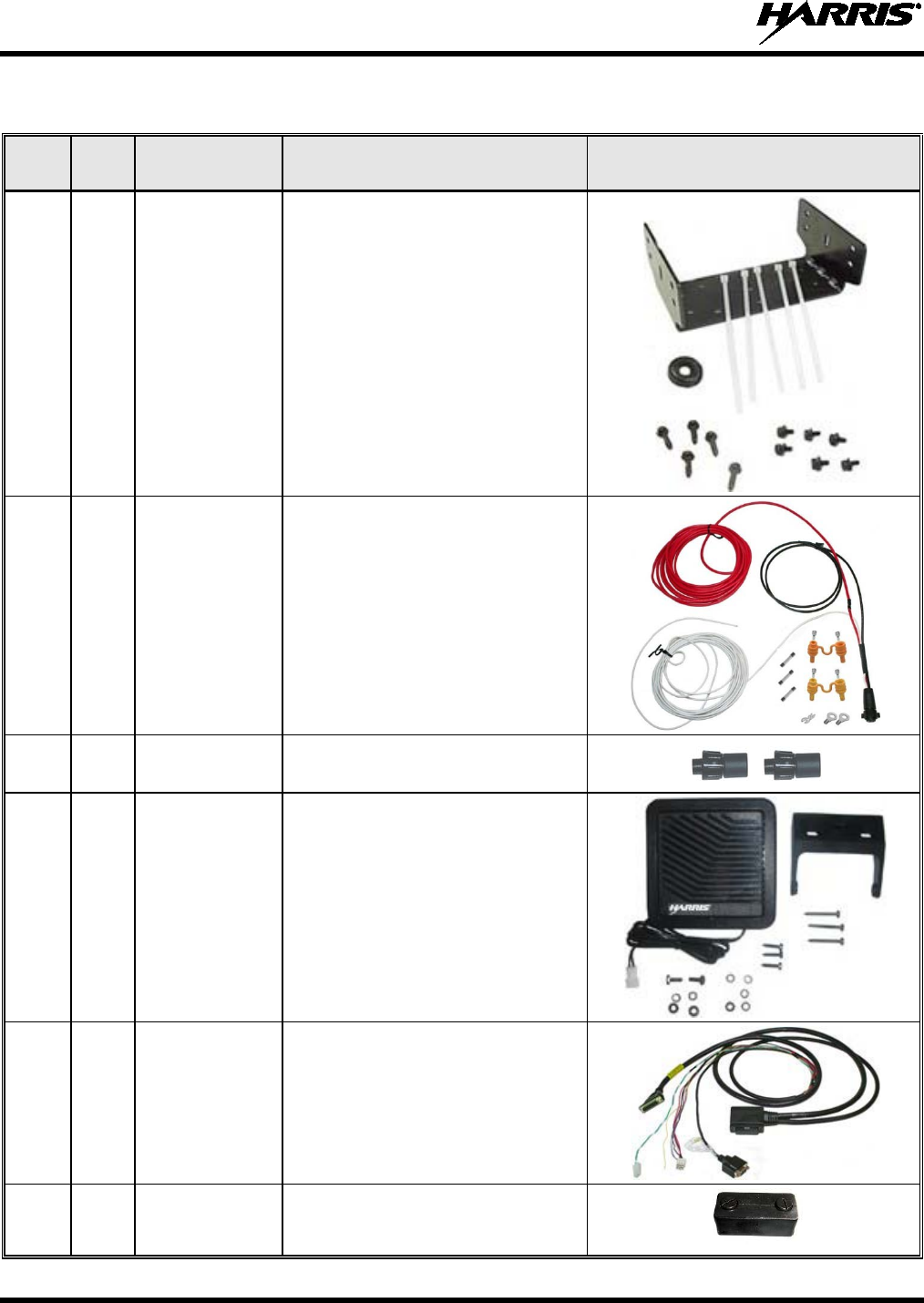
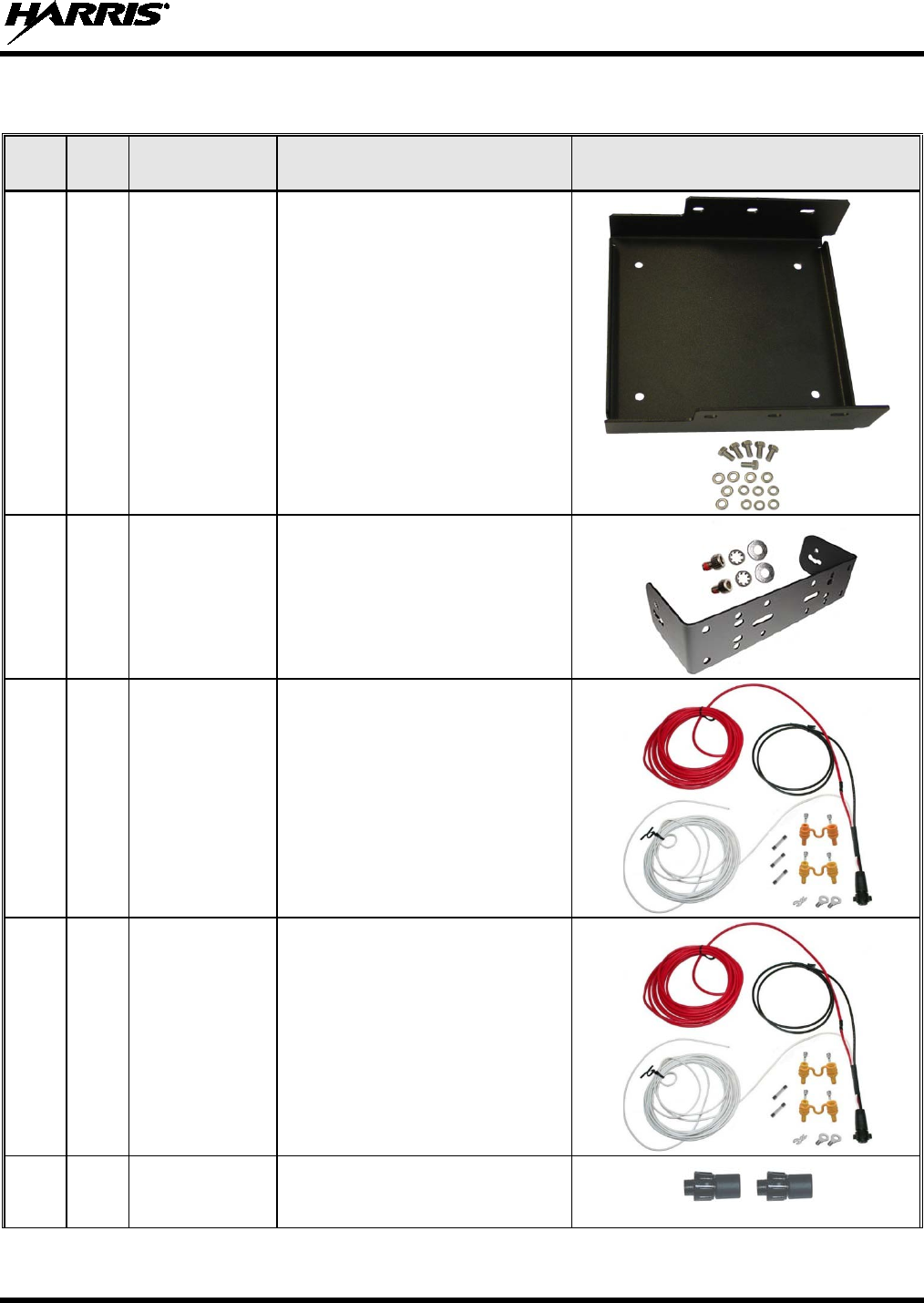
Table 4-4: Installation Kit MAMW-NZN6W
for Front-Mount M7300 Mobile Radio
ITEM QTY. PART
NUMBER DESCRIPTION ILLUSTRATION
1 1
KT101533V1 Kit, Front-Mount Mounting Bracket.
Includes M5300/M7100/M7300
Mounting
Bracket FM101319V1
(marked KTB0310), M5 stainless-
steel hardware to attach radio to
bracket, self-
tapping hardware to
attach bracket to mounting surface,
½-inch rubber grommet, and 7-inch
cable ties. See Section 7.1 on
page 51.
2 1
CA-012365-
001 Cable, M5300/M7300 DC Power.
Includes 10-AWG, 20-
Foot DC
Power Cable with straight
connector, (2) waterproof HFB fuse
holders, (1) 20-amp AGC fuse, (1)
15-amp AGC fuse and (1) 3-amp
AGC fuse. See
CAUTION that
follows. See Section 7.2 on page
55.
3 2
CD-014027-
001 Terminator, CAN; 3-Pin, Straight
Body. See Section 7.3 on page 60.
4 1
LS102824V10 Speaker, External Mobile; 20-Watt
(with 4.6-foot cable). See Section
9.1 on page 87.
5 1
CA-012349-
001 Cable, M5300/M7300 Option. See
Section 11.1 (page 90).
6 1
FM-104859-
001 Cap, Waterproof (For covering
M7300’s DB-
9 serial port
connector).
MM-014763-001, Rev. G
29
Table 4-5: Installation Kit MAMW-NZN7R
for Remote-Mount M7300 Mobile Radio with CH-721 Control Head
ITEM QTY. PART
NUMBER DESCRIPTION ILLUSTRATION
1 1
KT23117 Kit, Remote-Mount Mobile Radio
Mounting Bracket. Includes
M5
300/M7100/M7300 Mounting
Bracket FM103111V1 and M5
stainless-steel hardware to attach
radio to bracket. See Section 8.1
on page 61.
2 1
KT-008608 Kit, CH-
721 Mounting Bracket.
Includes (1) U-Shaped Mounting
Bracket and #8 stainless-steel
hardware to attach control head
to bracket. See Section 8.3.2 on
page 73.
3 1
CA-012365-001 Cable, M5300/M7300 DC Power.
Includes 10-AWG, 20-
Foot DC
Power Cable with straight
connector, (2) waterproof HFB
fuse holders, (1) 20-
amp AGC
fuse, (1) 15-amp AGC fuse and
(1) 3-amp AGC fuse. See the
CAUTION that follows and
Section 8.2 on page 65.
4 1
CA-012616-001 Cable, CH-721/HHC-731 DC
Power. Includes 12-AWG, 10-foot
DC Power Cable with straight
connector, (2)
waterproof HFB
fuse holders, (1) 3-
amp AGC
fuse, and (1) 5-amp AGC fuse.
See Section 8.3.4 on page 76.
5 2
CD-014027-
001 Terminator, CAN; 3-Pin, Straight
Body. See Section 8.3.3.2 on
page 76.
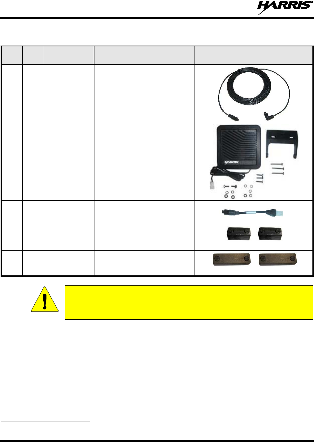
MM-014763-001, Rev. G
30
Table 4-5: Installation Kit MAMW-NZN7R
for Remote-Mount M7300 Mobile Radio with CH-721 Control Head
ITEM QTY. PART
NUMBER DESCRIPTION ILLUSTRATION
6 1
CA-009562-030 Cable, CAN; 30 feet, Right-Angle-
to-Straight Connectors. See
Section 8.3.3 on page 74
7 1
LS102824V10
Speaker, External Mobile;
20-Watt (with 4.6-foot cable). See
Section 9.2 on page 87.
8 1
MAMROS0034-
NN006 Cable, Speaker; 6-Inch, Straight
Connector. Section 9.2 on page
87.
9 2
FM-104859-
001 Cap, Waterproof (For DB-9 serial
port connector
s on radio and
control head.)
[See footnote 4]
10 2
FM-104859-
002 Cap, Waterproof (For DB-25
connector
s on radio and control
head.)
[See footnote 4]
The 20-amp fuse included with DC Power Cable CA-012365-001 should not be used in
the M7300 mobile radio application of this cable. M7300 radio main power should be
protected with the 15-amp fuse. Refer to Section 13 for additional information.
4 Earlier installation kits contained only one (1) each of FM-104859-001 and FM-104859-002.
CAUTION
(Continued)
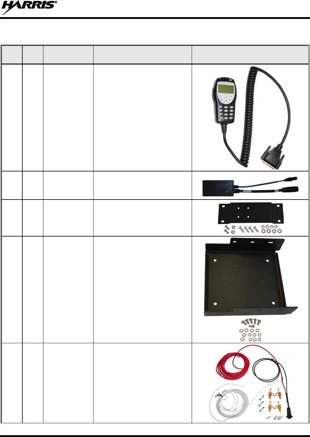
MM-014763-001, Rev. G
31
Table 4-6: HHC-731 Hand-Held Controller and Installation Components —
Installation Kit MAMW-NCP9P
ITEM QTY. PART
NUMBER DESCRIPTION ILLUSTRATION
1 1
CU-017821-001 Controller, Hand-Held, HHC-731
2 1
CA-018399-001 Cable, HHC-731 Interface
3 1
KT-018752-001 Kit, HHC-731
Interface Cable
Bracket
4 1
KT23117 Kit, Remote-Mount Mobile Radio
Mounting Bracket. Includes
M5300/M7100/M7300 Mounting
Bracket FM103111V1 and M5
stainless-steel hardware to attach
radio to bracket. See Section 8.1
on page 61.
5 1
CA-012365-001 Cable, M5300/M7300 DC Power.
Includes 10-AWG, 20-
Foot DC
Power Cable with straight
connector, (2) waterproof HFB
fuse holders, (1) 20-
amp AGC
fuse, (1) 15-amp AGC fuse and
(1) 3-
amp AGC fuse. See the
CAUTION on page 30 and
Section 8.2 on page 65.
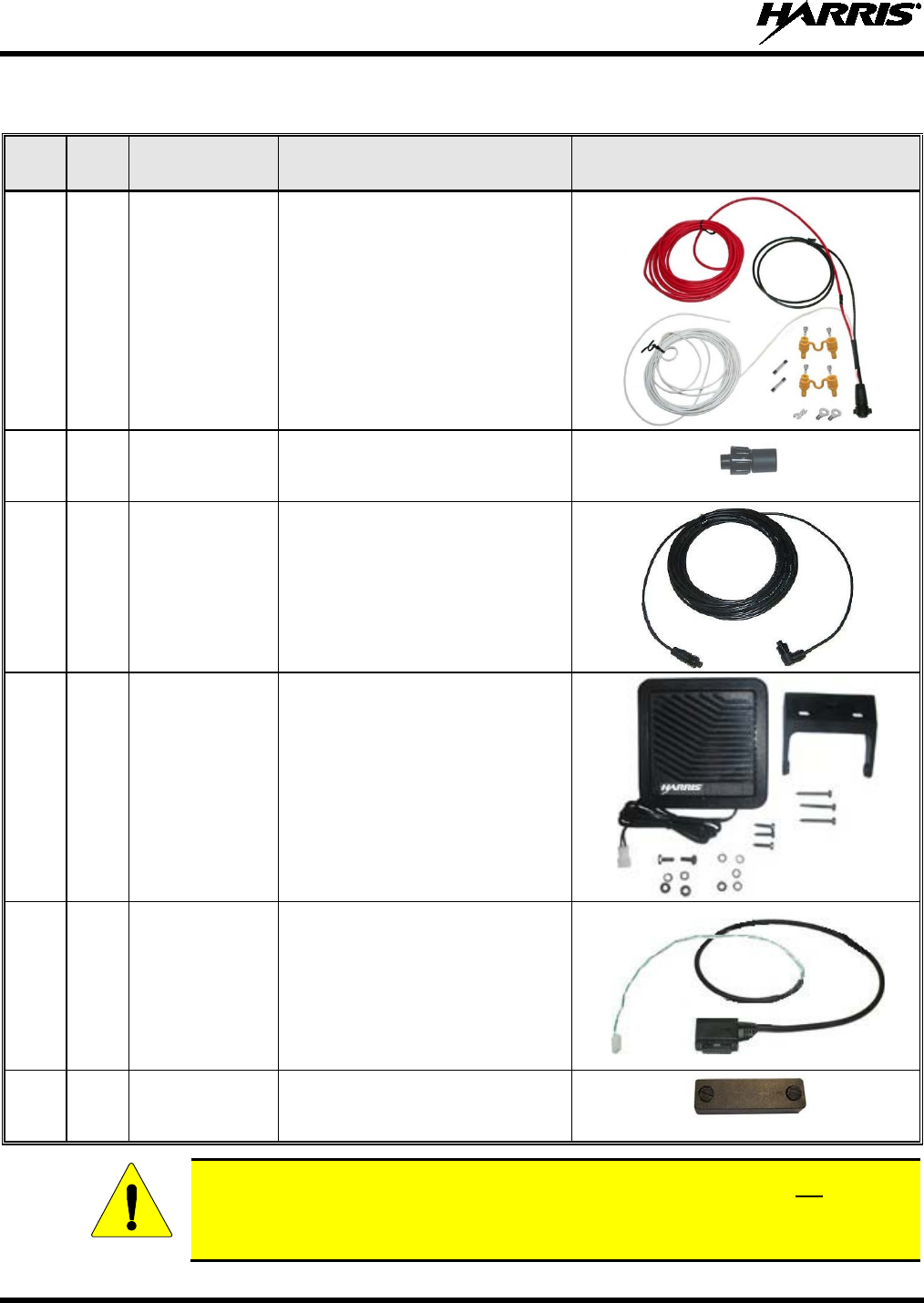
MM-014763-001, Rev. G
32
Table 4-6: HHC-731 Hand-Held Controller and Installation Components —
Installation Kit MAMW-NCP9P
ITEM QTY. PART
NUMBER DESCRIPTION ILLUSTRATION
6 1
CA-012616-001 Cable, CH-721/HHC-731 DC
Power. Includes 12-AWG, 10-foot
DC Power Cable with straight
connector, (2) waterproof HFB
fuse holders, (1) 3-
amp AGC
fuse, and (1) 5-amp AGC fuse.
See Section 8.4.3 on page 83.
7 1
CD-014027-001 Terminator, CAN; 3-Pin, Straight
Body. See Section 8.4.2 on page
82.
8 1
CA-009562-030 Cable, CAN; 30 feet, Right-Angle-
to-Straight Connectors
. See
Section 8.4.2 on page 82.
9 1
LS102824V10 S
peaker, External Mobile;
20-Watt (with 4.6-foot cable). See
Section 9.2.2 on page 88.
10 1
CA-012349-007 Cable, Speaker-Only Option,
20-feet. See Section 9.2.2 on
page 88.
11 1
FM-104859-002 Cap, Waterproof (For HHC-731
Interface Cable’s DB-25 option
connector.)
The 20-amp fuse included with DC Power Cable CA-012365-001 should not be used in
the M7300 mobile radio application of this cable. M7300 radio main power should be
protected with the 15-amp fuse. Refer to Section 13 for additional information.
CAUTION
(Continued)

MM-014763-001, Rev. G
33
Table 4-7: Additional Options and Accessories for M7300 Mobile Radios
PART NUMBER DESCRIPTION
AN102800V1 Antenna, 136 – 941 MHz Standard Rooftop-Mount; ¼-Wave*, 0 dBd Gain, with
Mounting Base, 17-foot (5.2-meter) RG-58 A/U (or equivalent) Low-Loss RF Cable
and Male TNC RF Connector; Field-Tuned*.
AN102800V2
(Discontinued) Antenna, 136 – 941 MHz Thick Rooftop-Mount; ¼-Wave*, 0 dBd Gain, with Mounting
Base, 17-foot (5.2-meter) RG-58 A/U (or equivalent) Low-Loss RF Cable and Male
TNC RF Connector; Field-Tuned*.
AN-125001-001 Antenna Mount: Standard Rooftop, NMO Mounting Base, 15-foot (4.6-meter)
RG-58 A/U (or equivalent) Low-Loss RF Cable, Male TNC RF Connector
AN-125001-002 Antenna Mount: Standard Rooftop, NMO Mounting Base, 15-foot (4.6-meter)
RF-195 (or equivalent) Low-Loss RF Cable, Male TNC RF Connector
AN-125001-003 Antenna Mount: Thick Rooftop, NMO Mounting Base, 15-foot (4.6-meter)
RG-58 A/U (or equivalent) Low-Loss RF Cable, Male TNC RF Connector
AN-125001-004 Antenna Mount: Thick Rooftop, NMO Mounting Base, 15-foot (4.6-meter) RF-195
(or equivalent) Low-Loss RF Cable, Male TNC RF Connector
AN-125001-005 Antenna Mount: GPS Combo Rooftop, NMO Mounting Base, 17-foot (5.1-meter)
RF-195 (or equivalent) Low-Loss RF Cable, Male TNC RF Connector; 17-foot
(5.1-meter) RG174/U (or equivalent) GPS RF Cable with Male SMA RF Connector
(attached); 2.7 to 3.3 Vdc or 4.8 to 5.2 Vdc Bias
AN-125001-006 Antenna Mount: GPS Combo Rooftop, NMO Mounting Base, 17-foot (5.1-meter)
RF-195 (or equivalent) Low-Loss RF Cable, Male TNC RF Connector; 17-foot
(5.1-meter) RG174/U (or equivalent) GPS RF Cable with Male SMA RF Connector
(attached); 2.7 to 3.3 Vdc or 4.8 to 5.2 Vdc Bias
AN-125001-007 Antenna Mount: Magnetic, NMO Mounting Base, 15-foot (4.6-meter) RG-58 A/U (or
equivalent) Low-Loss RF Cable, Male TNC RF Connector
AN-125001-008 Antenna Mount: Magnetic, NMO Mounting Base, 15-foot (4.6-meter) RF-195 (or
equivalent) Low-Loss RF Cable, Male TNC RF Connector
AN-225002-001 Antenna Element: 136 to 174 MHz, 0 dBd Gain, NMO, Factory-Tuned
AN-225004-001 Antenna Element: 450 to 512 MHz, 0 dBd Gain, NMO, Factory-Tuned
AN-225004-004 Antenna Element: 450 to 512 MHz, 0 dBd Gain, Low-Profile, NMO, Factory-Tuned
AN-225001-001 Antenna Element: 700/800 MHz, 3 dBd Gain, NMO, Factory-Tuned
AN-225001-002 Antenna Element: 700/800 MHz, 3 dBd Gain, Elevated-Feed, NMO, Factory-Tuned
AN-225001-003 Antenna Element: 700/800 MHz, 3 dBd Gain, Elevated-Feed No Ground Plane,
NMO, Factory-Tuned
AN-225001-004 Antenna Element: 700/800 MHz, 2 dBd Gain, Low-Profile, NMO, Factory-Tuned
AN-225001-005 Antenna Element: 700/800 MHz, 5 dBd Gain, NMO, Factory-Tuned
AN-025147-001
(Discontinued) Antenna, 136 to 174 MHz, Standard Rooftop-Mount; 0 dBd Gain, NMO Mounting
Base, 15-foot (4.6-meter) RG-58 A/U (or equivalent) Low-Loss RF Cable, Male TNC
RF Connector; Factory-Tuned.
AN-025147-003
(Discontinued) Antenna, 136 to 174 MHz, GPS Combo Rooftop-Mount; 0 dBd Gain, NMO Mounting
Base, 15-foot (4.6-meter) RG-58 A/U (or equivalent) Low-Loss RF Cable, Male TNC RF
Connector; 16.5-foot (5-meter) RG174/U (or equivalent) GPS RF Cable with Male SMA
RF Connector (attached); 2.7 to 3.3 Vdc or 4.8 to 5.2 Vdc Bias; Factory-Tuned.
AN-025147-005
(Discontinued) Antenna, 136 to 174 MHz, Magnetic-Mount; 0 dBd Gain, 15-foot (4.6-meter) RG-58 A/U
(or equivalent) Low-Loss RF Cable, Male TNC RF Connector; Factory-Tuned.

MM-014763-001, Rev. G
34
Table 4-7: Additional Options and Accessories for M7300 Mobile Radios
PART NUMBER DESCRIPTION
AN-025167-001
(Discontinued) Antenna, 700/800 MHz, Standard Rooftop-Mount, 3 dBd Gain, NMO Mounting Base,
15-foot (4.6-meter) RG-58 A/U (or equivalent) Low-Loss RF Cable, Male TNC and
Mini-UHF RF Connectors; Factory-Tuned.
AN-025167-002
(Discontinued) Antenna, 700/800 MHz, Elevated-Feed, Rooftop-Mount, 3d dB Gain, NMO Mounting
Base, 15-foot (4.6-meter) RG-58 A/U (or equivalent) Low-Loss RF Cable, Male TNC
and Mini-UHF RF Connectors; Factory-Tuned.
AN-025167-004
(Discontinued) Antenna, 700/800 MHz GPS Combo, Rooftop-Mount, 3 dBd Gain, NMO Mounting
Base, 15-foot (4.6-meter) RG-58 A/U (or equivalent) Low-Loss RF Cable, Male TNC
and Mini-UHF RF Connectors, 16.5-foot (5-meter) RG174/U (or equivalent) GPS RF
Cable with Male SMA RF Connector (attached); 2.7 to 3.3 Vdc or 4.8 to 5.2 Vdc
Bias; Factory-Tuned.
AN-025167-005
(Discontinued) Antenna, 700/800 MHz GPS Combo, Elevated-Feed Rooftop-Mount, 3 dBd Gain, NMO
Mounting Base, 15-foot (4.6-meter) RG-58 A/U (or equivalent) Low-Loss RF Cable, Male
TNC and Mini-UHF RF Connectors, 16.5-foot (5-meter) RG174/U (or equivalent) GPS
RF Cable with Male SMA RF Connector (attached); 2.7 to 3.3 Vdc or 4.8 to 5.2 Vdc Bias;
Factory-Tuned.
AN-025167-006
(Discontinued) Antenna, 700/800 MHz, Magnetic-Mount, 3 dBd Gain, 15-foot (4.6-meter) RG-58 A/U
(or equivalent) Low-Loss RF Cable, Male TNC and Mini-UHF RF Connectors;
Factory-Tuned.
AN-025167-010
(Discontinued) Antenna, 700/800 MHz, Low-Profile, Rooftop-Mount, 2 dBd Gain, NMO Mounting
Base, 15-foot (4.6-meter) RG-58 A/U (or equivalent) Low-Loss RF Cable, Male TNC
and Mini-UHF RF Connectors, Factory-Tuned.
AN-025167-011
(Discontinued) Antenna, 700/800 MHz GPS Combo, Low-Profile, Rooftop-Mount, 2 dBd Gain, NMO
Mounting Base, 15-foot (4.6-meter) RG-58 A/U (or equivalent) Low-Loss RF Cable,
Male TNC and Mini-UHF RF Connectors, 16.5-foot (5-meter) RG174/U (or equivalent)
GPS RF Cable with Male SMA RF Connector (attached); 2.7 to 3.3 Vdc or 4.8 to 5.2
Vdc Bias; Factory-Tuned.
AN-025167-014
(Discontinued) Antenna, 700/800 MHz, Standard Rooftop-Mount, 5 dBd Gain, NMO Mounting Base,
15-foot (4.6-meter) RG-58 A/U (or equivalent) Low-Loss RF Cable, Male TNC and
Mini-UHF RF Connectors, Factory-Tuned.
AN-025167-015
(Discontinued) Antenna, 700/800 MHz GPS Combo, Rooftop-Mount, 5 dBd Gain, NMO Mounting
Base, 15-foot (4.6-meter) RG-58 A/U (or equivalent) Low-Loss RF Cable, Male TNC
and Mini-UHF RF Connectors, 16.5-foot (5-meter) RG174/U (or equivalent) GPS RF
Cable with Male SMA RF Connector (attached); 2.7 to 3.3 Vdc or 4.8 to 5.2 Vdc
Bias; Factory-Tuned.
AN-025187-001
(Cat. No. MAMW-NAN5F)
Antenna, GPS Receive Only, Roof-Mount, 17-foot (5.2-meter) RG174/U (or
equivalent) RF Cable with Male SMA RF Connector (attached); 2.7 to 3.3 Vdc or 4.8
to 5.2 Vdc Bias.
AN-025187-003
(Cat. No. MAMW-NAN3L)
Antenna, GPS Receive Only, Magnetic-Mount, 17-foot (5.2-meter) RG174/U (or
equivalent) RF Cable with Male SMA RF Connector (attached); 2.7 to 3.3 Vdc or 4.8
to 5.2 Vdc Bias.
CA-012349-001
(Cat. No. MAMW-NCL8B) Cable, M5300/M7300 Option. See page 90.
CA-013671-020 Cable, TIA/EIA-232 Serial Programming (20 feet). See page 94.
CN-014756 Connector, RF; TNC Male Crimp-Type for RG58U, RG58A/U and RGU400 Coaxial
Cable.
(Continued)

MM-014763-001, Rev. G
35
Table 4-7: Additional Options and Accessories for M7300 Mobile Radios
PART NUMBER DESCRIPTION
KT-012350-001
(Cat. No. MAMW-NMK5F) Kit, GPS Receiver for M5300/M7300.
KT-015037 Kit, Front-Mount to Remote-Mount Conversion for M5300/M7300 Radio. Includes
CH-721 Conversion Kit, CH-721 Mounting Bracket Kit, CH-721 DC Power Cable,
CAN Cable, CAN Terminator, Speaker Cable, Etc.
KT-014494-002 Kit, Remote-Mount to Front-Mount Conversion for M5300/M7300 Radio and CH-721
Control Head.
CD-014027-001 Terminator, CAN; 3-Pin, Straight Body.
* Driven elements of AN102800V1 and AN102800V2 must be trimmed to proper lengths in order to minimize antenna
system VSWR.

MM-014763-001, Rev. G
36
Table 4-8: Additional Options and Accessories for CH-721 Control Heads
PART NUMBER DESCRIPTION
CA-009562-006 Cable, CAN; 6 feet, Right-Angle-to-Straight Connectors
CA-009562-030 Cable, CAN; 30 feet, Right-Angle-to-Straight Connectors
CA-009562-090 Cable, CAN; 90 feet, Right-Angle-to-Straight Connectors
CA-009562-250 Cable, CAN; 250 feet, Right-Angle-to-Straight Connectors
CA-011854-001 Cable, CH-721 Option
CA-104861 Cable, CH-721 Programming
MAMROS0075-N1210 Cable, DC Power; 12-AWG, 10-Foot, Straight Connector
MAMROS0075-N1220 Cable, DC Power; 12-AWG, 20-Foot, Straight Connector
MAMROS0075-R1210 Cable, DC Power; 12-AWG, 10-Foot, Right-Angle Connector
MAMROS0075-R1220 Cable, DC Power; 12-AWG, 20-Foot, Right-Angle Connector
MACDOS0012 Kit, Control Head Pedestal Mounting. Includes Pedestal Mount and Mounting
Screws
MACDOS0013-CN004 Kit, Speaker; 20-Watt, Straight Connector. (Includes 4-Ohm 20-Watt Speaker
LS102824V10 with 4.6-Foot Cable and 6-Inch Speaker Cable MAMROS0034-
NN006.)
FS24473 Kit, Vehicle Fuse and T-Tap. Includes (1) ATM Fuse Holder, (1) 2-Amp ATM Fuse,
(2) T-Tap Quick-Disconnect Terminals and (1) ¼-Inch Crimp Tab Terminal.
(Contents shown in Figure 8-12 on page 79.)
MC-101616-040
(Discontinued. Replaced by
MC-101616-041)
Microphone, Standard with Conxall Flush-Mount 45-Degree Connector
MC-101616-041 Microphone, Standard with Conxall Flush-Mount 90-Degree Connector
(Included with catalog number MAMW-NMC7Z)
MC-103334-040 Microphone, DTMF with Conxall Flush-Mount 45-Degree Connector
(Included with catalog number MAMW-NMC9C)
MC-103334-041 Microphone, DTMF with Conxall Flush-Mount 90-Degree Connector
MC-103334-050
(Discontinued. Replaced by
MC-103334-051)
Microphone, Noise-Canceling with Conxall Flush-Mount 45-Degree Connector
MC-103334-051 Microphone, Noise-Canceling with Conxall Flush-Mount 90-Degree Connector
(Included with catalog number MAMW-NMC9D)
344A4678P1 Microphone Hanger. (Included with catalog numbers MAMW-NMC7Z,
MAMW-NMC9C and MAMW-NMC9D)
CD-014027-001 Terminator, CAN; 3-Pin, Straight Body
MACDOS0010 Terminator, CAN; 3-Pin, Right-Angle Body
MM-014763-001, Rev. G
37
5 PLANNING THE INSTALLATION
5.1 GENERAL INFORMATION
Figure 5-1 on page 38 illustrates a typical front-mount radio installation, and Figure 5-2 on page 38
illustrates a typical remote-mount radio installation. Before starting, plan the installation carefully so it
will meet the following requirements:
• The installation is safe for the operator and passengers within the vehicle.
• The equipment is installed away from the airbag deployment areas.
• The installation allows for convenient access by the operator, as applicable (i.e., the control head or
hand-held controller).
• The equipment is protected from water damage.
• The installation is neat and allows easy service access.
• The mobile radio is mounted in a location assuring the vehicle occupant’s safety and out of the way
of passengers and auto mechanics.
A professional radio installer should perform the installation!
5.2 TOOLS REQUIRED
The following tools are recommended to complete the installation. Where specific vendor names and
model or part numbers are given, equivalent substitutes may be used:
• Non-Insulated Crimp Tool: Thomas & Betts
WT-111-M
• Phillips-Head Screwdrivers, #1 and #2
• Flat-Blade Screwdrivers, #1 and #2
• Insulated Terminal Crimp Tool: Klein 1005
• 4-Millimeter Hex Key Wrench
• Fuse Holder Crimp Tool: Thomas & Betts –
WT-112M or California Terminal Products
No. 1250 or Channelock No. 909
• ⅛-Inch Hex Key Wrench (Allen Wrench)
• 5/16-Inch Combination or Open-End Wrench
(Only Needed for GPS Receiver Option)
• 3-Blade Coax Cable Stripper for RG-58 Cable
similar to Tyco Electronics 1490490-1
(includes blades)
• ¾-Inch or ⅜-Inch Hole Saw with Depth
Protection: ¾-Inch = Ripley HSK 19 or
Antenex HS34; ⅜-Inch = Antenex HS38
• Ratcheting Hex-Crimp Tool for 50-Ohm TNC
and BNC RF Connectors and RG-58 Cable
similar to Tyco Electronics 58433-2 (includes
Crimper 354940-1 and Die Set 58436-1) or
Emerson Network Power 24-9960P
• Clutch-Type Cordless Drill with Drill Bits and
Driver Bits
• Deburring Tool (for ⅜-inch and smaller holes)
• Flush-Cut and Large Wire Cutters
• Non-Metallic Fish Tape, 25-Foot: Klein-Lite
50156 • Various Fasteners (e.g., machine screws and
nuts, Tek screws, etc.)
• Various Socket and Driver Sets
• Tie Wraps: Nylon, 6-inches or larger
•
Soft-Jaw Pliers: Tessco 450520 or equivalent
A separate list of test equipment is included in Section 14.2 on page 104.
CAUTION
NOTE
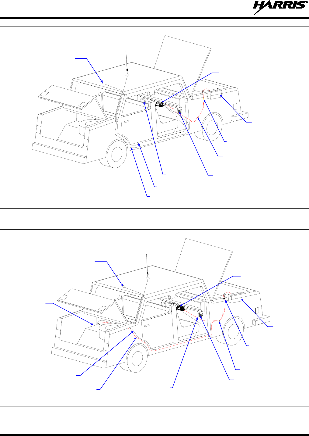
MM-014763-001, Rev. G
38
Figure 5-1: Typical Front-Mount Mobile Radio Installation in a Standard Passenger Vehicle
Figure 5-2: Typical Remote-Mount Mobile Radio Installation in a Standard Passenger Vehicle
VEHICLE
BATTERY
GROMMET
(MOUNTED IN FIREWALL)
SPEAKER
IN-LINE WATERPROOF FUSE
HOLDER & AGC FUSE
(15-AMP FOR RADIO)
MOBILE
ANTENNA
GPS ANTENNA
M7300 FRONT-MOUNT
MOBILE RADIO
VEHICLE
FUSE BOX
GPS ANTENNA CABLE
MOBILE ANTENNA CABLE
VEHICLE
BATTERY
GROMMET
(Mounted in vehicle’s firewall)
SPEAKER
IN-LINE WATERPROOF FUSE
HOLDERS AND AGC FUSES
(15-AMP FOR RADIO)
(5-AMP FOR CONTROL HEAD)
(Supplied with DC Power Cables)
CONTROL HEAD
MOBILE
ANTENNA
GPS ANTENNA
(Optional)
M7300 TRUNK-
MOUNT MOBILE
RADIO
CAN CABLE
(To/From Control Head)
10-AWG RED WIRE OF RADIO’S DC POWER CABLE
(Carries DC power from fuse holder at battery to radio)
NOTE: SEE TEXT FOR WIRING
OF DC POWER CABLE.
12-AWG RED WIRE OF CONTROL
HEAD’S DC POWER CABLE
(Carries DC power from fuse holder
at battery to control head)
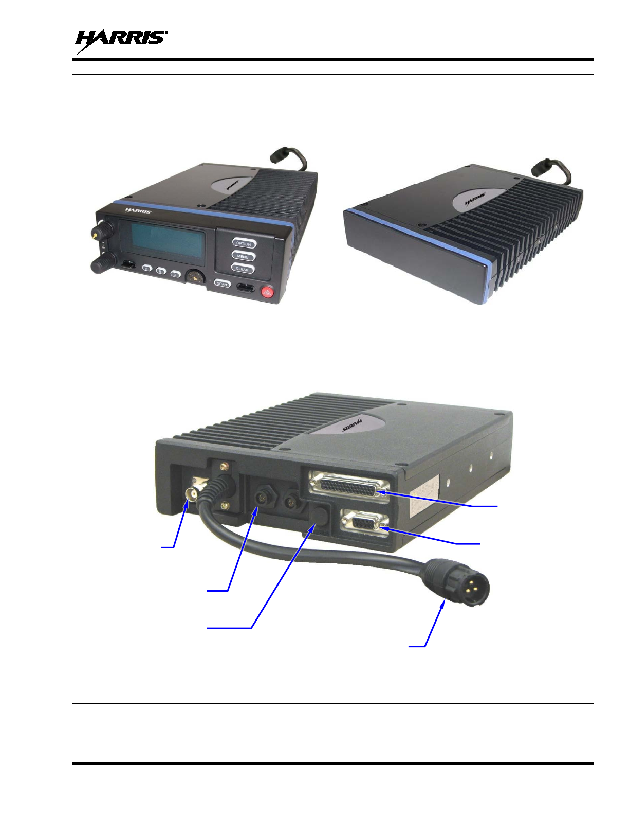
MM-014763-001, Rev. G
39
FRONT VIEWS
Front-Mount M7300 Mobile Radio Remote-Mount M7300 Mobile Radio
(With Scan Control Head)
REAR VIEW
Figure 5-3: M7300 Front-Mount and Remote-Mount Mobile Radios — Front and Rear Views
CAN Port Connectors
(2 places)
Antenna
Connector
(female TNC)
DC Power Cable
(with 3-Pin Connector)
GPS Antenna Port
(optional)
44-Pin I/O
Connector
9-Pin Serial Port
Connector
MM-014763-001, Rev. G
40
5.3 LOCATING COMPONENTS
Plan the mounting locations of all components (radio, control head/hand-held controller, antenna, and
cables) and determine the routes for all wiring and cables. Particularly consider the connection of the
radio for planning purposes.
• Determine the customer’s preferences, if any, for location of components. Comply with these
preferences as long as they are consistent with safety recommendations and guidelines presented in
this manual, and other generally accepted professional radio installation practices.
• For a front-mount installation, the radio is typically located under the vehicle’s dash panel. However,
it may be mounted above the dash, or at some other location per customer requirements, available
space, and/or mounting surface strength. Dimensions for the radio, control head, and hand-held
controller are listed in Section 2.1 on page 17. As noted in that section, these dimensions do not
include space required at the rear of the radio for cables. Several inches of clearance space is required.
• For a remote-mount radio installation, the radio is typically located in the motor vehicle’s trunk, or
some other preferably unoccupied section in a vehicle, such as a fire truck’s equipment shelf. The
control head is typically located under the vehicle’s dash panel. Dimensions for the radio, control
head, and hand-held controller are listed in Section 2.1 on page 17. As noted in that section, these
dimensions do not include space required at the rear of the radio and control head for cables. Several
inches of clearance space is required at the back of the control head, and at least six (6) inches is
recommended at the back of the radio. In addition, several inches of clearance space is required at
each side of the radio for access to the screws that secure the radio to its mounting bracket.
• When selecting a mounting location, verify sufficient clearance behind the radio can be maintained so
cables will not be stressed, crushed, twisted, or bent at severe angles. This also applies to the control
head in a remote-mount radio installation. Also, the front and sides of the units must have clearance
for air circulation, access to mounting screws, mounting hardware, etc.
• Verify the drilling of holes and the insertion of screws will not damage or interfere with any existing
vehicle components (for example, a fuel tank, fuel lines, the transmission housing, etc.), or any
existing vehicle wiring.
• For antenna location and installation-related information, refer to Section 6.
The radio must be kept out of direct sunlight and away from heat sources. Adequate
free-air
ventilation must be provided to its rear fins. The radio will automatically
reduce its transmit
RF output power when its ambient temperature exceeds
approximately +140° Fahrenheit (+60° Celsius).
All cables should have a service loop near each connector end. Do not bend the cables
at severe angles near the connector end. Above all, after all components are installed,
verify no cable is under any tension. Failure to do so may lead to damaged cables,
causing intermittent radio operation or complete radio failure.
CAUTION
CAUTION

MM-014763-001, Rev. G
41
6 ANTENNA INSTALLATION
6.1 ANTENNA MOUNTING LOCATIONS
At this time, review all information presented in the
REGULATORY AND
SAFETY INFORMATION section of this manual (see page 7
). A transmitting
antenna must be installed in accordance with the guidelines presented in both the
REGULATORY AND SAFETY INFORMATION section, and in this section. As a
guide f
or determining the best possible mounting location in order to reduce
human exposure to radio frequency (RF) electromagnetic energy during transmit
mode, use Table 1-1 for a VHF radio, Table 1-3 for a 700 and 800 MHz radio, and
Figure 6-1.
Antennas must be mounted in one of four (4) possible locations on the vehicle. Figure 6-1 shows the
recommended locations and antenna part numbers. Also, see Table 4-7 for additional information. Always
follow the antenna manufacturer’s instructions when mounting an antenna.
6.1.1 Direct Center or Center-Rear of Rooftop
The center of the vehicle’s roof is the best location for a rooftop-mount antenna (location in Figure
6-1). For optimal performance, the mounting area under the antenna must be a flat with a minimum
radius of six (6) inches of metal ground plane. It must be located directly in the center of the roof to
minimize human exposure to RF electromagnetic energy. Other obstructions such as a light bar or another
antenna may prevent the antenna from being mounted in the direct center of the roof. In this case, the
antenna should be mounted a minimum of one foot away from and behind the obstruction but in the
middle of the roof with respect to the left and right sides of the vehicle (location in Figure 6-1).
6.1.2 Center of Trunk Lid
Certain vehicles do not allow for the antenna to be placed in the center or center-rear of the roof. In this
case, the next best location for the antenna is in the direct center of the trunk lid (location in Figure
6-1). In this case, an elevated-feed-point antenna is recommended. Although this type of antenna does
not require a metal ground plane, it must be located directly in the center of the trunk lid to minimize
human exposure to RF electromagnetic energy.
6.1.3 Rear Deck Lid for Stand-Alone GPS Receive Antenna
If the M7300 mobile radio does not use a GPS combination-type antenna and it is equipped with a GPS
receiver, a stand-alone GPS receive antenna must be separately located and mounted. The vehicle’s rear
deck lid (location in Figure 6-1) is the recommended mounting location for this case. This locates the
GPS antenna inside the vehicle.
WARNING
MM-014763-001, Rev. G
42
TOP VIEW OF A TYPICAL VEHICLE
ANTENNA
PART NUMBER ANTENNA DESCRIPTION* LOCATION(S)
AN102800V1 136 to 941 MHz Standard Rooftop-Mount, ¼-Wave, 0 dBd Gain
AN102800V2 (Discontinued) 136 to 941 MHz Thick Rooftop-Mount, ¼-Wave, 0 dBd Gain
AN-125001-001 (mount) with
AN-225002-001 (element) 136 to 174 MHz Standard Rooftop-Mount, 0 dBd Gain
AN-125001-003 (mount) with
AN-225002-001 (element) 136 to 174 MHz Thick Rooftop-Mount, 0 dBd Gain
AN-125001-007 (mount) with
AN-225002-001 (element) 136 to 174 MHz Magnetic-Mount, 0 dBd Gain
AN-125001-001 (mount) with
AN-225004-001 (element) 450 to 512 MHz Standard Rooftop-Mount, 0 dBd Gain
AN-125001-001 (mount) with
AN-225004-004 (element) 450 to 512 MHz Standard Rooftop-Mount, Low Profile, 0 dBd Gain
AN-125001-003 (mount) with
AN-225004-001 (element) 450 to 512 MHz Thick Rooftop-Mount, 0 dBd Gain
AN-125001-003 (mount) with
AN-225004-004 (element) 450 to 512 MHz Thick Rooftop-Mount, Low Profile, 0 dBd Gain
AN-125001-005 (mount) with
AN-225004-001 (element) 450 to 512 MHz GPS Combo Rooftop-Mount, 0 dBd Gain
AN-125001-005 (mount) with
AN-225004-004 (element) 450 to 512 MHz GPS Combo Rooftop-Mount, Low Profile, 0 dBd Gain
AN-125001-007 (mount) with
AN-225004-001 (element) 450 to 512 MHz Magnetic-Mount, 0 dBd Gain
AN-125001-007 (mount) with
AN-225004-004 (element) 450 to 512 MHz Magnetic-Mount, Low Profile, 0 dBd Gain
AN-125001-002 (mount) with
AN-225001-001 (element) 700/800 MHz Standard Rooftop-Mount, 3 dBd Gain
AN-125001-002 (mount) with
AN-225001-002 (element) 700/800 MHz Elevated-Feed Rooftop-Mount, 3 dBd Gain
AN-125001-002 (mount) with
AN-225001-003 (element) 700/800 MHz Elevated-Feed No Ground Plane Rooftop-Mount, 3 dBd
Gain
AN-125001-002 (mount) with
AN-225001-004 (element) 700/800 MHz Low-Profile Rooftop-Mount, 2 dBd Gain
AN-125001-002 (mount) with
AN-225001-005 (element) 700/800 MHz Standard Rooftop-Mount, 5 dBd Gain
AN-125001-004 (mount) with
AN-225001-001 (element) 700/800 MHz Thick Rooftop-Mount, 3 dBd Gain
Trunk Lid
Rooftop
Hood
MM-014763-001, Rev. G
43
TOP VIEW OF A TYPICAL VEHICLE
ANTENNA
PART NUMBER ANTENNA DESCRIPTION* LOCATION(S)
AN-125001-004 (mount) with
AN-225001-002 (element) 700/800 MHz Elevated-Feed Thick Rooftop-Mount, 3 dBd Gain
AN-125001-004 (mount) with
AN-225001-003 (element) 700/800 MHz Elevated-Feed No Ground Plane Thick Rooftop-Mount,
3 dBd Gain
AN-125001-004 (mount) with
AN-225001-004 (element) 700/800 MHz Low-Profile Thick Rooftop-Mount, 2 dBd Gain
AN-125001-004 (mount) with
AN-225001-005 (element) 700/800 MHz Thick Rooftop-Mount, 5 dBd Gain
AN-125001-006 (mount) with
AN-225001-001 (element) 700/800 MHz GPS Combo Rooftop-Mount, 3 dBd Gain
AN-125001-006 (mount) with
AN-225001-002 (element) 700/800 MHz GPS Combo Elevated-Feed Rooftop-Mount, 3 dBd Gain
AN-125001-006 (mount) with
AN-225001-003 (element) 700/800 MHz GPS Combo Elevated-Feed No Ground Plane Rooftop-
Mount, 3 dBd Gain
AN-125001-006 (mount) with
AN-225001-004 (element) 700/800 MHz GPS Combo Low-Profile Rooftop-Mount, 2 dBd Gain
AN-125001-006 (mount) with
AN-225001-005 (element) 700/800 MHz GPS Combo Rooftop-Mount, 5 dBd Gain
AN-125001-008 (mount) with
AN-225001-001 (element) 700/800 MHz Magnetic-Mount, 3 dBd Gain
AN-125001-008 (mount) with
AN-225001-002 (element) 700/800 MHz Magnetic-Mount Elevated-Feed, 3 dBd Gain
AN-125001-008 (mount) with
AN-225001-003 (element) 700/800 MHz Magnetic-Mount Elevated-Feed No Ground Plane, 3 dBd
Gain
AN-125001-008 (mount) with
AN-225001-004 (element) 700/800 MHz Magnetic-Mount Low-Profile, 2 dBd Gain
AN-125001-008 (mount) with
AN-225001-005 (element) 700/800 MHz Magnetic-Mount, 5 dBd Gain
AN-025147-001 (Discontinued) 136 to 174 MHz Standard Rooftop-Mount, 0 dBd Gain
AN-025147-003 (Discontinued) 136 to 174 MHz GPS Combo Rooftop-Mount, 0 dBd Gain
AN-025147-005 (Discontinued) 136 to 174 MHz Magnetic-Mount, 3 dBd Gain
AN-025167-001 (Discontinued) 700/800 MHz Standard Rooftop-Mount, 3 dBd Gain
AN-025167-002 (Discontinued) 700/800 MHz Elevated-Feed Rooftop-Mount, 3 dBd Gain
AN-025167-004 (Discontinued) 700/800 MHz GPS Combo Rooftop-Mount, 3 dBd Gain
AN-025167-005 (Discontinued) 700/800 MHz GPS Combo Elevated-Feed Rooftop-Mount, 3 dBd Gain
Trunk Lid
Rooftop
Hood
MM-014763-001, Rev. G
44
TOP VIEW OF A TYPICAL VEHICLE
ANTENNA
PART NUMBER ANTENNA DESCRIPTION* LOCATION(S)
AN-025167-006 (Discontinued) 700/800 MHz Magnetic-Mount, 3 dBd Gain
AN-025167-010 (Discontinued) 700/800 MHz Low-Profile Rooftop-Mount, 2 dBd Gain
AN-025167-011 (Discontinued) 700/800 MHz GPS Combo Low-Profile Rooftop-Mount, 2 dBd Gain
AN-025167-014 (Discontinued) 700/800 MHz Standard Rooftop-Mount, 5 dBd Gain
AN-025167-015 (Discontinued) 700/800 MHz GPS Combo Rooftop-Mount, 5 dBd Gain
AN-025187-001 GPS Receive Only, Roof-Mount
AN-025187-003 GPS Receive Only, Magnetic-Mount
* See Table 4-7 on page 33 for detailed antenna descriptions.
Figure 6-1: Recommended Antenna Mounting Locations with Antenna Part Numbers
6.2 ANTENNA INSTALLATION PROCEDURES
An antenna must be installed before completing the radio installation.
Table 4-7 (page 33) and Figure 6-1 (page 44) list the mobile radio antennas available for use with the
radio. As presented in the previous section, various mounting locations exist. Optimal performance is
achieved via a rooftop antenna mounted in the direct center of the motor vehicle’s roof.
6.2.1 Installing NMO Antenna Mounts AN-125001-001, -002, -003 and -004
These NMO style antenna mounts can each be used with several different antenna elements. Only limited
access under the mounting location is typically required. The installation procedure is presented in
Section 6.2.1.3.
6.2.1.1 Standard NMO Antenna Mounts AN-125001-001 and AN-125001-002
These standard ¾-inch NMO antenna mounts require a ¾-inch hole in a relatively flat area of the vehicle
body, with a vehicle metal thickness of between 0.020 and 0.040 inches. AN-125001-002 has a very-low-
loss coax cable (LMR/RF-195 or equivalent).
6.2.1.2 Thick-Roof NMO Antenna Mounts AN-125001-003 and AN-125001-004
Both of these thick-roof NMO antenna mounts use either a ⅜-inch or a ¾-inch mounting hole in a
relatively flat area of the vehicle body, with a vehicle metal thickness of between 0.040 and 0.1875 inches
NOTE
Trunk Lid
Rooftop
Hood
MM-014763-001, Rev. G
45
(3/16-inch maximum thickness). AN-125001-004 has a very-low-loss coax cable (LMR/RF-195 or
equivalent).
For thick-roof NMO antenna mounts AN-125001-003 or AN-125001-004, using a
⅜-inch mounting hole will require better
access to the underside of the mounting
location than if a ¾-inch hole is used. This is because, in the case of a ⅜-inch hole, the
antenna mount’s bushing assembly must
be inserted from the underside of the
mounting surface.
When using a ¾-inch mounting hole to mount thick-roof NMO
antenna mounts
AN-125001-003 or AN-125001-004, the thickness of the mounting surface must be at
least ⅛-inch (0.125-inch minimum thickness). This requirement is due to the thickness
of the alignment ring used to center the bushing assembly within the ¾-inch mounting
hole.
6.2.1.3 Installation Procedure for Mounts AN-125001-001 through -004
1. Select the antenna mounting location in accordance with the information presented in Sections 1 and
6.1 of this manual. If necessary, contact the Technical Assistance Center for assistance. See page 25
for TAC contact information.
2. Verify no obstructions exist immediately below the respective mounting location on the underside of
the vehicle body, such as vehicle ribbing/body framing, a wiring harness, air bag equipment, etc. Also
verify there is a sufficient access path and clearance for the mount’s coax cable. If there is an
obstruction or insufficient clearance, select another nearby mounting location.
3. Measure and mark the center point of the selected antenna mounting location. Be sure to center the
mark from side-to-side of the vehicle.
4. Obtain a hole saw specifically designed for drilling NMO mounting holes of the required diameter.
(e.g., Antenex/Laird Technologies model HS34 or equivalent for a ¾-inch hole; Antenex/Laird
Technologies model HS38 or equivalent for a ⅜-inch hole).
5. If the vehicle’s headliner panel, carpet, seats, or otherwise, is below the mounting location, move or
remove the headliner panel, etc. as necessary to protect it. Alternately, apply a heat-resistant mask
material (such as a fiberglass mat or thin sheet metal with masked edges) as required to “catch” the
metal shavings and the metal plug (if any) produced by the hole saw. The plug (if any) may be
relatively hot if/when it drops out of the saw upon completion of the hole drilling process. ⅜-inch
diameter hole saws generally produce only shavings, not plugs.
6. With the hole saw and a drill, drill a hole at the marked hole center point. Position the drill square to
(i.e., 90 degrees from) the vehicle mounting surface so paint immediately outside of the perimeter of
the hole is evenly removed.
Excessive use of the hole saw and/or failure to position the drill “square” with
(i.e., at a 90-degree angle from)
the vehicle mounting surface may result in
damage to the metal mounting surface, in the area immediately outside of the
perimeter of the hole.
7. Ensure the saw removed the paint immediately around the hole as the drilling operation completes. If
not, do so by reinserting the saw completely into the hole and spinning it as required. This allows
proper grounding via the mount’s lock nut on the top of the mounting surface. On the bottom of the
mounting surface, the “teeth” of the mount’s bushing assembly may not provide a good ground due to
thick vehicle undercoating, thick primer, oxidation/rust, etc.
NOTE
CAUTION
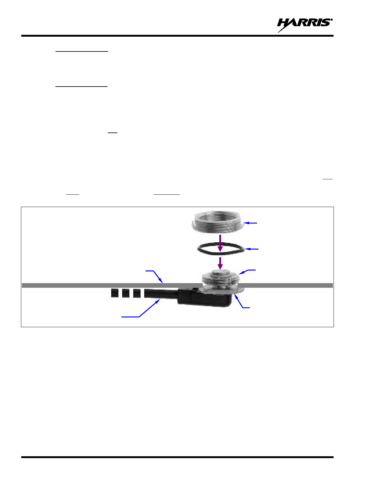
MM-014763-001, Rev. G
46
8. For a ¾-inch hole, feed the unterminated end of the mount’s coax cable into the hole from the top
surface of the vehicle until the mount’s bushing assembly is in position to drop into the hole. The
bushing should be tilted at a slight angle and fed into the hole. The threaded shank of the mount’s
bushing assembly will not fall through a ¾-inch hole.
For a ⅜-inch hole, feed the threaded shank of the mount’s bushing assembly into the hole from the
underside of the mounting surface. Hold it into position until the lock nut is installed.
9. If installing a thick-roof antenna mount (⅜-inch shank) into a ¾-inch hole, place the alignment ring
onto the threaded shank of the mount. This ring has an approximate ¾-inch outside diameter.
10. A tube of synthetic lubricant is included with the antenna mount. Apply this lubricant to the mount’s
rubber O-ring. Do not get any lubricant on the center contact of the mount’s bushing assembly.
11. As illustrated in Figure 6-2 and Figure 6-3, add the O-ring (C) and lock nut (D) to the top of the
mount’s bushing assembly (A). With the O-ring in the groove in the underside of the lock nut, thread
the lock nut onto the bushing assembly. Be sure the O-ring remains in the groove before tightening
the lock nut.
12. Using a 15/16-inch open-end wrench, tighten the lock nut until it fully compresses the O-ring and
makes good contact with the vehicle mounting surface. The groove’s ridges on the bottom of the lock
nut must make full contact with the unpainted metal surface of the vehicle.
13. Install the antenna element per the procedure in Section 6.2.4.
Figure 6-2: Installing a Standard ¾-Inch NMO Antenna Mount
(e.g., AN-125001-001 or AN-125001-002)
Coax Cable
(Partial)
Rubber O-Ring (C)
Vehicle Mounting Surface
(top side)
Bushing Assembly (A)
Lock Nut (D)
Threaded Shank (B)
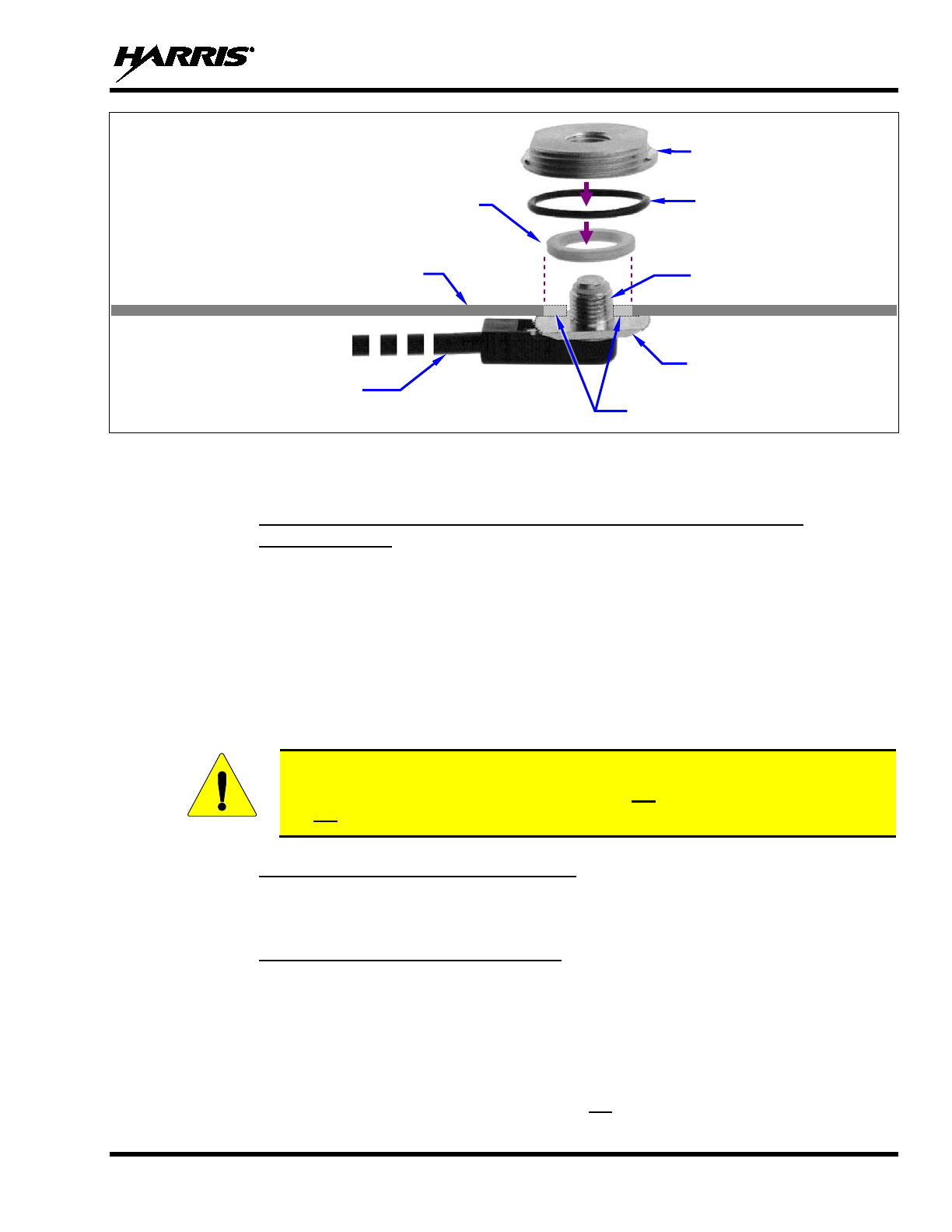
MM-014763-001, Rev. G
47
Figure 6-3: Installing a Thick-Roof NMO Antenna Mount
(e.g., AN-125001-003 or AN-125001-004)
6.2.2 Installing NMO Magnetic Antenna Mounts AN-125001-007 and
AN-125001-008
1. Thoroughly clean the bottom of the magnetic mount and the selected vehicle mounting surface by
removing all dust, dirt, etc.
2. Carefully place the magnet mount onto the metal surface of the vehicle at the selected location. The
coax cable exiting the mount’s base should be orientated towards the point at which it will enter into
the interior of the vehicle. Do not try to reposition it by sliding it on a painted metal surface.
3. Route the mount’s coax cable to the radio location, passing it by the trunk lid’s perimeter gasket, door
perimeter gasket, etc., as necessary.
4. Install the antenna element per the procedure in Section 6.2.4.
To remove a magnetic antenna mount, hold it at the bottom of its base and tilt it at an
angle to release the magnetic attraction force. Do not pull on the mount’s coax cable.
Do not drag the mount across the mounting surface.
6.2.3 Installing All Other Antenna Mounts
For any other type of antenna mount not covered in the previous sections, such as GPS combination
antennas, install the mount in accordance with the installation instructions included with the mount.
6.2.4 Attaching NMO Antenna Elements
1. Clean the top surface of the NMO mount and the surface of the vehicle immediately around the
mount.
2. Place the gasket included with the antenna element (not pictured in Figure 6-2 or Figure 6-3) around
the mount and against the surface of the vehicle. If a lubricant or sealant was included with the
gasket, apply it to the gasket before placing the gasket.
3. Apply the antenna element to the top of the mount and tighten it in a clock-wise direction (as viewing
from the top). Use an appropriate wrench if required. Do not over-tighten.
CAUTION
Coax Cable
(Partial)
Rubber O-Ring (C)
Vehicle Mounting Surface
(top side)
Bushing Assembly (A)
Lock Nut (D)
Threaded Shank (B)
Alignment Ring
(Used only with ¾-inch mounting hole)
(Extensions shown to illustrate a
⅜-Inch hole vs. a ¾-inch hole.)
MM-014763-001, Rev. G
48
4. Install a placard (not supplied) on the vehicle’s dash panel, in accordance with the following
CAUTION. Place the placard in plain view of the vehicle operator’s position.
Before entering any automatic vehicle (“car”) wash equipment,
remove the antenna
element from the antenna mount, and secure the element in a safe location inside the
vehicle. This will prevent the wash equipment from damaging the element and/or
mount. After exiting the wash equipment, thoroughly dry the top of the mount before
re-installing the element.
5. Continue with the connection procedure presented in the next section.
6.2.5 Installing the Coax Cable and TNC RF Connector
1. Route the coax cable from the antenna mount to the location where the mobile radio will be installed.
Remove headliner panel, interior panels, etc., as necessary. The cable must be kept out of casual
contact from persons within the vehicle. Tie and stow the cable as necessary to protect it from
possible chafing. Observe and follow this WARNING:
Antennas Having Part Numbers Beginning with AN-025167, and Antennas
AN102800V1 and AN102800V2: The cables of these antennas should never be cut to
a shorter length. Instead, excess cable must be tied and stowed. This not only prevents
the antenna from radiating above its intended or configured power, but it also allows
for future re-installation considerations such as a relocation of the mobile radio
within the vehicle. Installations requiring longer cables are treated as custom and
separately specified.
All Other Antennas/Antenna Mounts:
The antenna cables of all other
antennas/antenna mounts can be cut to a length
no shorter than six (6) feet
(1.83 meters), as measured from the base of the antenna mount.
2. Using an appropriate crimp tool, crimp the supplied TNC RF connector to the end of the antenna
cable. For crimping instructions, see Figure 6-4 or the instructions supplied with antenna mount.
3. The antenna cable is connected to the radio’s TNC receptacle-type (female) RF connector per a
procedure presented later in this manual. The cable and its TNC connector must be protected from
damage, dirt, and/or metal shavings which may be generated during the mechanical and electrical
installation of the radio. Temporarily tying the connector and cable-end within a small plastic bag is
recommended.
CAUTION
WARNING
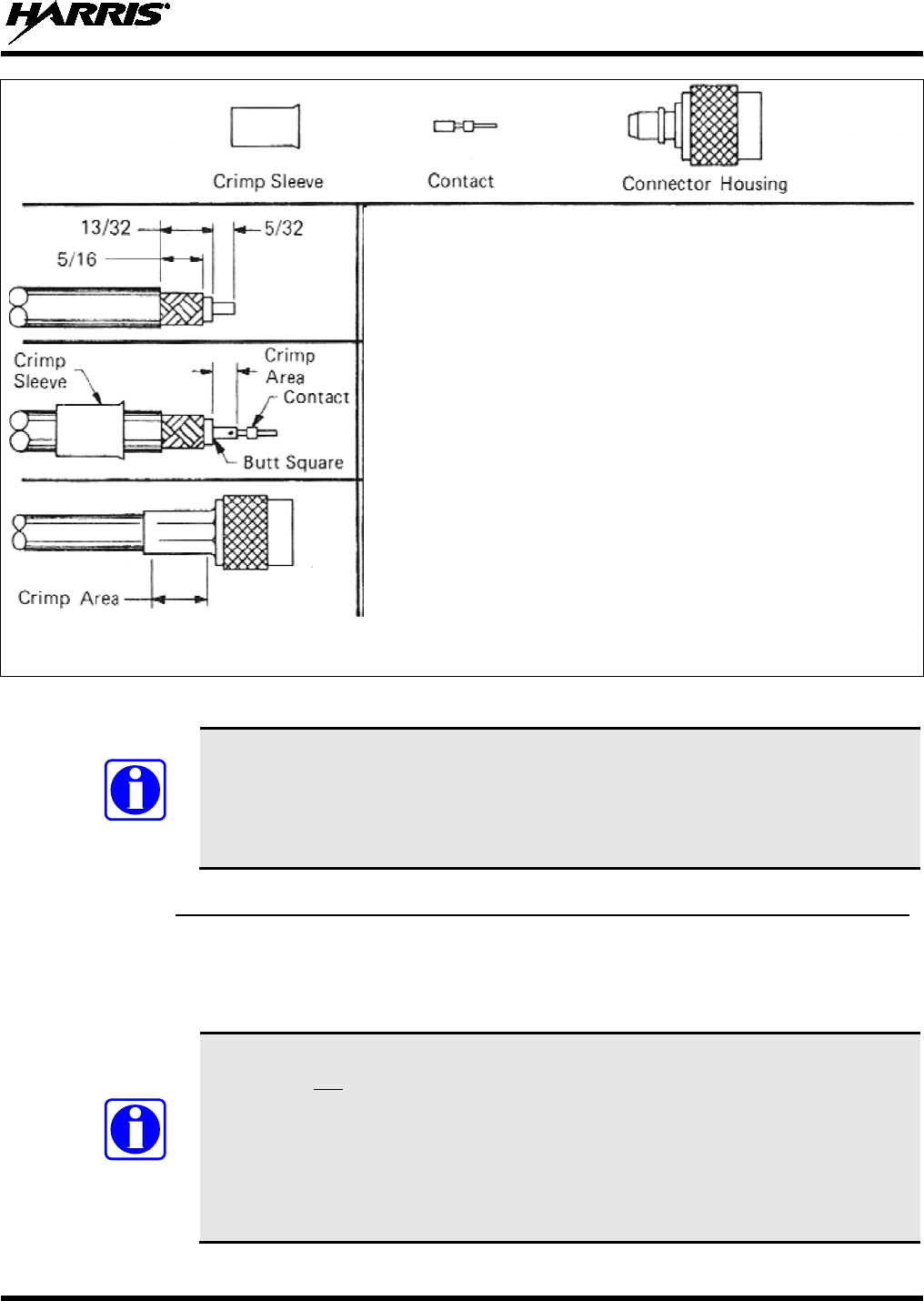
MM-014763-001, Rev. G
49
Actual Size; Dimensions are in Inches
(VS-AN-025167-010 Rev. A)
Figure 6-4: Crimping Instructions for TNC RF Connector
If the mobile radio installation includes a unity-gain antenna
part number
AN102800V1 or AN102800V2, the antenna element must be tuned (trimmed) for
maximum performance (i.e., minimum reflection) during the test procedures presented
in Section 14. Other antennas used with the M5300 are factory-tuned and therefore do
not require tuning in the field.
6.2.6 Install GPS Antenna (Required Only if Radio has GPS Receiver Option)
If the M7300 radio is equipped with the GPS receiver option, the GPS receiver requires connection to an
externally-mounted GPS antenna. The GPS antenna must be kept at least six (6) inches away from any
other antenna mounted on the vehicle and it must have at least six inches of surface ground plane beneath
it. The following antenna installation procedure is recommended:
Connection to a GPS antenna is only required if the (optional) GPS receiver is installed
in the radio and if its functions will be utilized/required. For OpenSky radio system
applications, the GPS receiver can provide GPS data to either a locally-connected
computer/mobile data terminal, or over-the-air to the radio network. For
EDACS/ProVoice, P25 and conventional radio system applications, the GPS receiver
is typically only used to support a computer/mobile data terminal (MDT) running GPS
software connected to the radio via NMEA-formatted serial data link. Refer to Section
12 for additional information.
NOTE
NOTE
1. Before cutting the cable to a shorter length, refer to the previous
WARNING. Some antenna cables should never to cut, while others
can be cut to as short as 6 feet.
2. Trim the end of the cable to the dimensions shown at the left, taking
care not to nick the cable’s inner conductor or its braid/shield.
3. Slip the crimp sleeve over the end of the cable, with its flanged-end
facing towards the end of the cable.
4. Place the contact onto the cable’s inner conductor. The end of the
con
tact and the cable’s inner dielectric must “butt square” together, as
shown to the left.
5. While
holding the contact tight against the dielectric, crimp the contact
to the inner conductor using an appropriate crimp tool.
6.
Flair the cable’s outer braid/shield and then gently but firmly push the
contact (and cable end) into the connector housing until
a gentle snap
is felt, indicating the contact is locked in place.
7. Slip the crimp sleeve in place, butting its flanged-end against the
connector housing.
8. Using an appropriate crimp tool, crimp the crimp sleeve securely to
the cable end and connector housing. When crimping, hold the
housing and sleeve firmly together, and to the cable end.

MM-014763-001, Rev. G
50
A combination (“combo”) antenna kit includes a GPS antenna built into the base of the
mobile antenna. Refer to Table 4-7 (page 33) and/or Figure 6-1 (page 44) for available
combo antennas.
1. After selecting a mounting location, refer to the antenna manufacturer’s mounting and testing
instructions for installation guidance. Install the antenna in accordance with these instructions. If
necessary, contact the Technical Assistance Center. See page 25 for TAC contact information. Do not
alter the GPS antenna cable length; tie and stow excess cable as necessary.
2. Route the cable from the antenna base to the location of where the radio will be installed. Remove
headliner panel, interior panels, etc., as necessary. The cable must be kept out of casual contact from
persons within the vehicle. Tie and stow it as necessary to protect it from possible chafing.
3. The antenna cable is connected to the radio’s SMA receptacle-type (female) RF connector per a
procedure presented later in this manual. The cable and its (male) SMA connector must be protected
from damage, dirt, and/or metal shavings which may be generated during the mechanical and
electrical installation of the radio. Temporarily tying the connector and cable-end within a small
plastic bag is recommended.
NOTE
MM-014763-001, Rev. G
51
7 FRONT-MOUNT RADIO INSTALLATION
This section includes detailed instructions for mechanically installing and wiring a
front-mount M7300 mobile radio. For remote-mount M7300
mobile radio installation
procedures, refer to Section 8 which begins on page 61.
7.1 MOUNTING THE FRONT-MOUNT RADIO
The Mounting Bracket Kit for the front-mount M7300 mobile radio includes a heavy-gauge steel
U-shaped mounting bracket. The radio should be attached to a mounting surface using this bracket. The
bracket can be mounted above or below the radio. Kit contents are shown in Figure 7-2, and bracket
dimensions are shown in Figure 7-3.
Both the radio and the mounting bracket have multiple holes in both sides for adjusting the radio within
the bracket. The design allows for both front-to-rear tilting of the radio within the bracket for best viewing
angle, and a front-to-rear position offset. The radio has six (6) threaded mounting holes, three (3) per side,
and the mounting bracket has ten (10) corresponding holes, five (5) per side. The radio must be secured to
the bracket using at least four of the six M5 socket-head screws included in the Mounting Bracket Kit (2
screws per side).
Typically, the radio is front-to-rear centered within the bracket. However, it can be front-to-rear offset by
approximately 2 inches (5.1 centimeters), if required. Also, the radio can be positioned straight in the
bracket (i.e., parallel with the bottom surface of the bracket), or it can be tilted up or down at an angle of
between approximately 10 to 20 degrees. When positioned straight and centered front-to-rear within the
bracket, the radio extends approximately 2.5 inches (6.4 centimeters) from the front and rear edges of the
bracket. In the rear, additional clearance must be included for cables. The area directly at the front of the
radio must be completely clear of all objects (e.g., gear shift, other radio equipment, etc.) so the operator
can easily access and visualize the radio’s control head.
The mounting bracket must be attached to a secure metal surface that meets or exceeds the minimum
1/16-inch-thick steel sheet metal requirement in accordance with the following WARNING. For example,
it can be attached directly to the bottom of the dash if the gauge of the sheet metal is high and the surface
is firm and flat, or it can be attached to the transmission hump, etc., if a mounting wedge (not included) is
utilized. The front-mount M7300 radio weighs approximately 9.2 pounds (4.17 kilograms).
At a minimum, the mounting surface should be 16-gauge (approximately 1/16-inch
thick) steel sheet metal. Mounting to plastic or other material with low tensile and
shear strength could lead to an unsafe and/or failed mounting condition, turning
the radio and its mounting bracket into a projectile during a high-shock incident
such as a motor vehicle accident. If the selected mounting surface does not meet
the minimum 16-gauge
steel sheet metal requirement, the surface should be
reinforced with a metal backing plate (not supplied) or it should be reinforced
using some other approved mounting method.
In addition to improving safety of the installation, firm mounting also prevents
unreasonable vibration that could damage the radio, adversely affect transceiver
performance and/or cause its cable connections to loosen. An improperly mounted
M7300
radio may experience degradation in the quality of voice and data
communications.
NOTE
WARNING
CAUTION
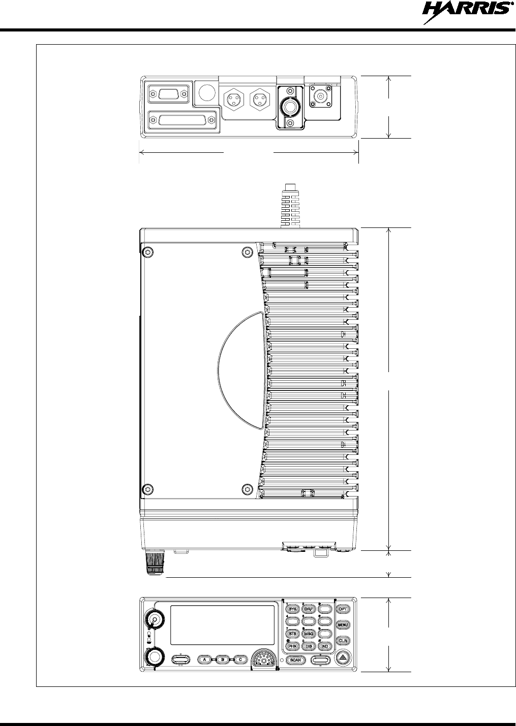
MM-014763-001, Rev. G
52
Figure 7-1: Front-Mount M7300 Radio Dimensions
REAR VIEW
TOP
VIEW
10.5 inches
(267 mm)
2.38 inches
(60 mm)
2.0 inches
(51 mm)
FRONT VIEW
6.9 inches
(175 mm)
(Partial View of
DC Power Cable)
0.8 inches
(20 mm)
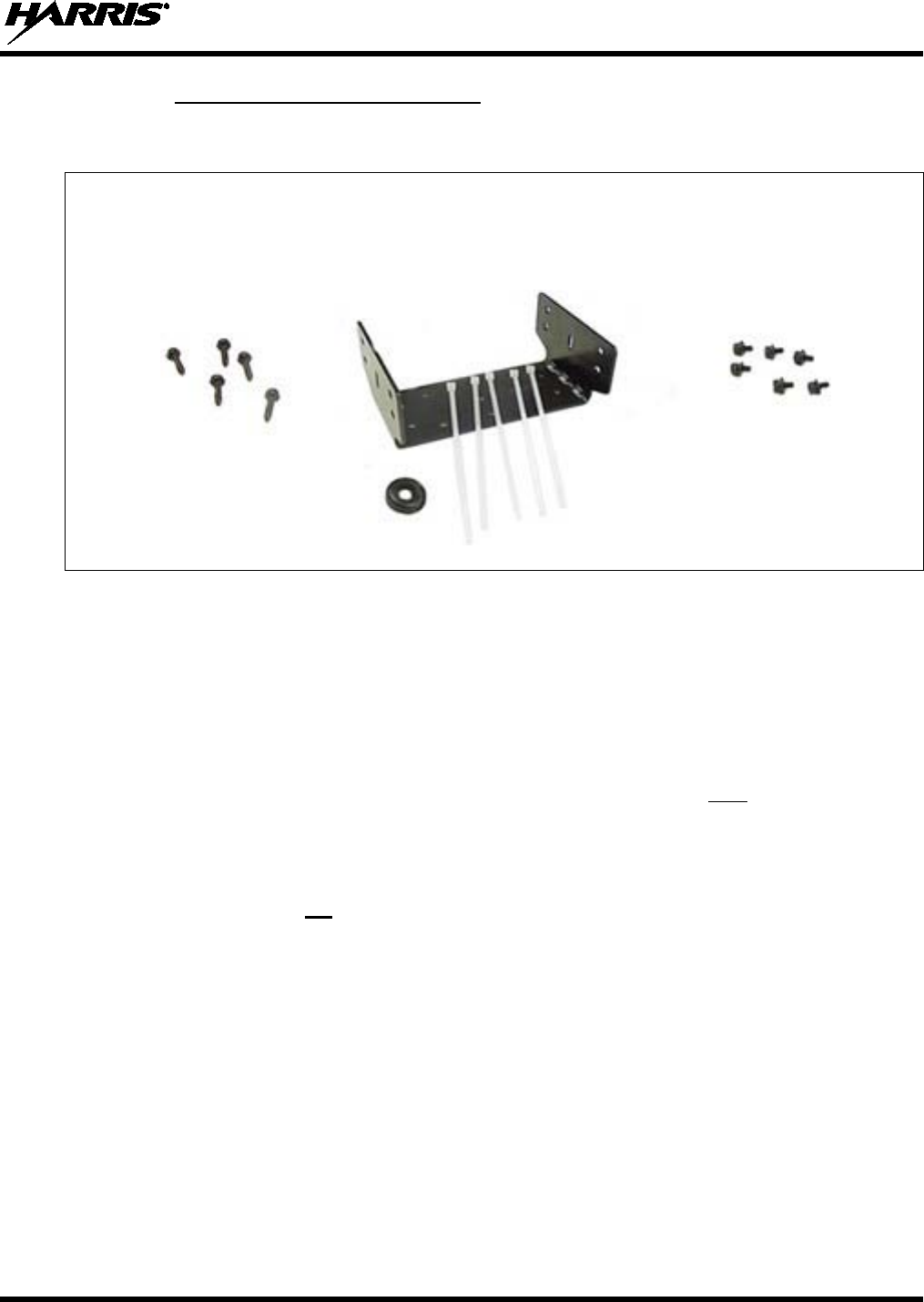
MM-014763-001, Rev. G
53
7.1.1 Mounting Bracket Installation
The front-mount M7300 radio’s mounting bracket is included with the Front-Mount Mounting Bracket
Kit KT101533V1. Kit contents are shown in Figure 7-2. This kit is Item 1 listed in Table 4-4 (page 28).
Mounting Bracket
Self-Tapping Screws for FM101319V1
Securing Bracket (Marked KTB0310), M5 Hardware for
to Mounting Surface Ties and Grommet Securing Radio to Bracket
Figure 7-2: Front-Mount Mounting Bracket Kit KT101533V1
When selecting a mounting location for the radio, verify sufficient clearance can be maintained around
the radio for installation and service access. A minimum clearance of approximately four (4) inches
(10 centimeters) is recommended at the rear, left and right sides of the radio. As previously stated, the
area directly at the front of the radio must be completely clear of objects so the operator can easily access
and visualize the radio’s control head.
As illustrated in Figure 7-3, the bracket is both left-to-right and front-to-rear symmetrical. It has eleven
(11) holes for securing it to a mounting surface. At least four (4) of these holes must be used to secure the
bracket to the mounting surface. Five 20-millimeter-long self-tapping screws are included in the
Mounting Bracket Kit for this purpose. However, some other type of hardware (not supplied) may be
used, such as #10-32 stainless-steel self-locking hardware (i.e., machine screws with washers and locking
nuts), or self-drilling screws. Self-drilling screws such as “TEK” screws do not require drilling of a pilot
hole prior to installation. Do not use common self-threading sheet metal screws because they will loosen
over time with vehicle vibrations.
The following mounting procedure is recommended:
1. Determine the best radio-to-bracket position and angle by test-fitting the radio into the mounting
bracket at the selected vehicle mounting location. Slide the radio between the sides of the bracket and
temporarily secure it to the bracket with several of the M5 socket-head screws from the bracket kit.
When positioned straight and centered front-to-rear within the bracket, the radio extends
approximately 2.5 inches (6.4 centimeters) from the front and rear edges of the bracket. In the rear,
additional clearance must be included for cables. The area directly at the front of the radio must be
completely clear of all objects (e.g., gear shift, other radio equipment, etc.) so the operator can easily
access and visualize the radio’s control head.
2. At the rear of the radio, verify sufficient clearance is available for cables and service access.
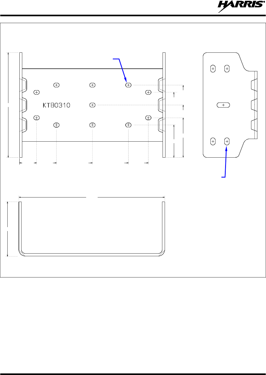
MM-014763-001, Rev. G
54
TOP VIEW SIDE VIEW
(Dimensions in Inches)
FRONT/REAR VIEW
(Dimensions in Inches)
(Made From KBT0310B)
Figure 7-3: Mounting Bracket FM101319V1 (Marked KTB0310) Dimensions
[for Front-Mount M7300 Mobile Radio (Radio Not Shown)]
3. If the mounting surface is not flat (such as the top of a transmission hump), construct a suitable
mounting wedge as necessary, and attach the wedge to the surface using an approved attachment
method. Never mount the bracket directly to a non-flat surface.
4. On the mounting surface, mark the selected location for the bracket, and then remove the radio from
the bracket.
5. Clean and remove any foreign material from the mounting surface.
6. Using the bracket as a template, and/or the dimensional information shown in Figure 8-3, mark and
drill at least four (4) mounting holes into the mounting surface as required per the type of hardware
used.
5.16
0.83 1.81 3.59 5.36 6.34
1.59
1.95
2.58
(FM101319V1)
B
3.56
3.20
7.17
2.68
Bracket-To-Vehicle
Screw Holes (11 places)
Bracket-To-Radio Screw Holes
(10 places, 5 each side)
MM-014763-001, Rev. G
55
Before drilling holes and/or installing mounting screws, verify these operations will not
damage or interfere with any existing vehicle component (the fuel tank, a fuel line, the
transmission housing, existing vehi
cle wiring, etc.). Always check to see how far the
mounting screws will extend below the mounting surface prior to installation. Always
deburr drilled holes before installing screws.
7. Temporarily remove the bracket and deburr all of the newly drilled holes.
8. If necessary, apply an approved paint or rust-inhibitor at the holes in the mounting surface.
9. Set the bracket back into place.
10. Install and tighten the mounting screws/hardware.
11. Verify the bracket is firmly secured to the mounting surface. A secure mount prevents unreasonable
vibration, which could damage the radio and/or cause its cable connections to loosen.
12. If the rear of the radio is easily accessible when the radio is positioned in the selected position within
the bracket, it is recommended that the radio be temporarily inserted into the bracket. Otherwise, do
not mount the radio into the bracket at this time, because several cable connections must be made at
the rear of the radio.
7.1.2 Inserting the Radio into the Mounting Bracket
The radio should now be inserted into the mounting bracket according to this procedure:
1. Lay the radio into the mounting bracket with the front of the radio facing in the correct direction
(usually towards the rear of the vehicle).
2. Secure the radio to the bracket using at least four (4) of the six (6) M5 x 10 mm stainless-steel socket-
head screws included with the Mounting Bracket Kit. These screws have captive lockwashers. Kit
contents are shown in Figure 7-2. This kit is Item 1 listed in Table 4-4 (page 28).
3. Tighten all screws using a 4-millimeter hex key wrench until each lockwasher is fully compressed
and the radio is firm and flush in between the brackets.
4. Check the mounting area for proper clearance for cable service looping and for air circulation, plus an
area to secure and rest the excess cable lengths.
Proper mounting is one factor that ensures optimal radio performance. An improperly
mounted radio may experience degradation in the quality of voice and data
communications.
7.2 FRONT-MOUNT RADIO’S DC POWER INSTALLATION
7.2.1 Overview of On/Off Power Wiring Configurations
The following power wiring configurations are supported:
• Radio turns on and off automatically with vehicle’s ignition switch/key — This configuration
allows the on/off state of the vehicle’s ignition switch/key to control the on/off power state of the
radio. The white wire of the radio’s DC Power Cable is connected to a fused switched power source,
typically identified as vehicle “Accessory” power. This source must switch on (up to positive (+)
battery voltage potential) when the vehicle’s ignition switch/key turns on, and it must switch off (to
CAUTION
NOTE
MM-014763-001, Rev. G
56
near zero volts) when the ignition switch/key turns off. The required fuse rating is 3 amperes. When
using this configuration, the on/off/volume control must be left in the on position for automatic
power-up/down to function properly.
In a front-mount M7300 radio installation, to fuse the white wire of the radio’s DC
Power Cable, a yellow waterproof (HFB type) fuse holder and a 3-amp AGC fuse are
included with the cable.
• Radio turns on and off with a manual switch — This configuration is used when, for example, the
radio has to remain on even when the ignition key must be removed from the vehicle and a separate
on/off switch is acceptable. The white wire of the radio’s DC Power Cable is connected to one side of
a manually-controlled switch, and the other side of this switch is connected to unswitched and fused
vehicle power. The required fuse rating is 3 amperes. When using this configuration, the
on/off/volume control must be left in the on position for automatic power-up/down to function
properly.
• Radio turns on with its on/off/volume control (“hot wired”) — This configuration allows radio
on/off power control only via its on/off/volume control. It may be desired if, for example, the radio
has to remain on even when the ignition key must be removed from the vehicle and a separate on/off
switch is not desired and/or not acceptable. The white wire of the radio’s DC Power Cable must be
connected to unswitched and fused vehicle power. The required fuse rating is 3 amperes.
In all of the above cases, the radio’s main DC power input (red wire) must be connected through an in-
line fuse to unswitched vehicle DC power. The red wire must be connected to raw battery power (positive
battery terminal) via the supplied fuse.
Any DC input power
provided to the radio shall be no higher or lower than
13.6 volts DC ±10%. The DC input power should be free and clear of any AC noise or
DC spikes above 18 v
olts. If the vehicle cannot meet these requirements, then DC
conditioning will be required before any DC power is connected to the radio. This
includes conditioning for both the radio’s main DC power input lead and for its
switched ignition sense power input. DC conditioning can be accomplished by a noise
filter or DC isolation equipment such as Harris part number FL-018314-001 or FL-
018314-002, or similar units with equal specifications. The fuse must be placed in-line
before any noise filter. Contact TAC for additional information.
7.2.2 DC Power Cable and Main Fuse Holder Installation
The radio’s DC Power Cable has a 3-pin connector, a 20-foot red wire (for the main power connection), a
20-foot white wire (for the switched power source connection), and a 4-foot black wire (for the ground
connection). It is supplied with waterproof fuse holders, two AGC-type fuses, and non-insulated ring
terminals. The following installation procedures are recommended:
7.2.2.1 Black Wire Connection (Ground Wire)
1. Connect the radio’s DC Power Cable to the radio by mating its 3-pin connector to the radio’s 3-pin
power cable connector as follows: Visually align the key and firmly push and turn the outer locking
ring clockwise until it stops. A click will be sensed to confirm proper mating.
2. Prepare to connect the cable’s black wire to vehicle ground by locating an area of vehicle metal
within approximately two (2) feet of the radio. This surface must have a solid and stable connection
to vehicle ground. If not, add grounding strap(s) as necessary.
NOTE
CAUTION
MM-014763-001, Rev. G
57
3. Strip the area of any paint or dirt to expose a bare metal surface, approximately ¾-inch square.
4. Drill a hole in the approximate center of the bare metal surface, and deburr it. A ⅜-inch non-
insulated ring terminal is supplied with the cable to make this ground connection. Therefore, hole
diameter should be appropriate for the utilized grounding screw/bolt size and type used to connect the
ring terminal to the bare metal surface. This hardware is not supplied.
5. Cut the black wire to the required length plus some additional length for a service loop, then strip
insulation back approximately ¼-inch.
6. Crimp a ⅜-inch non-insulated ring terminal (supplied with the cable) to the end of the black wire.
7. Attach the ring terminal and black wire to the bare metal surface using stainless-steel self-locking
hardware (i.e., machine screws with washers and locking nuts) or other appropriate hardware to
ensure a reliable terminal-to-metal contact. Tighten securely.
8. Apply an approved paint or rust-inhibitor over the remaining exposed bare metal surface and around
the ring terminal.
7.2.2.2 Red Wire and Main Fuse Holder Connection (Radio’s Main Power Wire)
1. Continue installation of the radio’s DC Power Cable by routing its 20-foot 10-AWG red wire to the
location of the vehicle’s battery (or its main DC bus bar or stud). Remove interior panels, door kick
panels, etc., and route the wire through existing channels in the vehicle body as necessary. Protect the
wire from possible chafing where necessary. Tie and stow the wire as necessary.
Plan the routing of the 10-AWG red wire carefully, using an existing access hole in the
vehicle’s firewall if possible. Alternately, drill a new hole approximately ½-inch in
diameter and install a small rubber grommet (one supplied with the bracket kit) to
protect the wire from chafing at the hole’s sharp metal edge. To prevent fumes from
entering the passenger compartment, this hole/grommet/wire combination must
also be sealed with a silicon-based sealer before completing the installation.
Do not install any wiring or fuse holder over or in the near vicinity of the vehicle’s
engine. Excessive engine heat can cause permanent damage to these components and
can lead to intermittent electrical connection to the battery.
Before making connections to the battery’s positive post, carefully disconnect the
battery’s negative (ground) cable(s). This will prevent tools or other metallic
objects which come in contact with the battery’s positive terminal from shorting to
vehicle ground, causing sparks or even a fire or an explosion! When disconnecting
the negative cable(s), cover/insulate the positive post(s) if it is not already so a tool
cannot short between the posts. Some vehicles, such as those with diesel engines
have more than one battery; in this case, disconnect the negative cables at all
batteries.
Radio fuses should not
be installed until all wiring is complete. This will prevent
the radio from powering up prematurely and/or causing an in-rush of current that
could lead to shorting of the battery, sparks, or even fire.
2. Obtain the orange waterproof (HFB type) fuse holder included with the DC Power Cable.
3. Observe and follow the previously presented WARNING!
CAUTION
CAUTION
WARNING
MM-014763-001, Rev. G
58
4. Cut the red wire to the required length for connection to the battery’s positive (+) battery terminal (or
the main DC bus bar or stud).
5. Prepare to splice the fuse holder into the red wire by cutting it again, at approximately three (3) to six
(6) inches from the end.
6. Strip all three (3) wire ends back approximately ⅜-inch, place a fuse holder shell on each wire, and
securely crimp a fuse holder terminal to each wire end. Before crimping, verify fuse holder shells are
oriented in the correct directions (i.e., with each large end towards the wire end).
7. Label this fuse holder and red wire appropriately (e.g., “M7300 Main Power: 15-AMP FUSE”).
8. Do NOT install a fuse into the fuse holder at this time.
9. Crimp an appropriate electrical terminal to the short red wire. A corrosion-resistant ⅜-inch ring
terminal is included with the cable for this purpose, but another size corrosion-resistant terminal type
(not supplied) may be used if required.
10. Connect the ring terminal directly to the battery’s positive post (or if present, to a stud on the battery’s
main/non-switched power distribution terminal block).
A front-mount M7300 mobile radio installation may be equipped with additional CH-721
control heads in a multi-head installation. In this case, refer to Section 8.3 (begins on page
71) for control head installation procedures.
7.2.2.3 White Wire Connection
A review of the information presented in Section 7.2.1 (page 55) may be beneficial at this time. As
required per the chosen power-up configuration, connect the white wire by following one of the three
procedures presented in the respective sub-section that follows.
7.2.2.3.1 Radio Turns On and Off with Vehicle’s Ignition Switch/Key
With this wiring configuration, the radio (and its control head) automatically turns on and off with the
vehicle’s ignition switch/key. The white wire is sometimes referred to as the “white ignition switch wire”
or the “ignition sense input wire.” In this configuration, the white wire connects to a switched power
source, typically identified as “Accessory” power, that switches on and off with the vehicle’s ignition
switch/key. When using this configuration, the CH-721 control head’s on/off/volume control must be left
in the on position for automatic power-up/down to function properly.
The white ignition sense wire must be connected to a fused power source that switches
from approximately zero volts to approximately +13.6 volts when the vehicle’s ignition
switch/key is turned from the OFF position to the ACCESSORY and RUN positions.
Use of a switched power source that is subject to voltage changes as a result of other
actions, such as opening a vehicle door, may result in undesirable radio power cycles.
1. Locate the vehicle’s switched ignition or “Accessory” power connection point that will be used for
the switched ignition 12-volt DC power source. This point is typically located at or near the vehicle’s
fuse panel. It may be necessary to consult the vehicle manufacturer’s wiring diagram.
2. Route the white wire of the radio’s DC Power Cable from the back of the radio to the area near this
connection point. Protect the wire from possible chafing as necessary.
3. Obtain the other waterproof (HFB-type) fuse holder included with the radio’s DC Power Cable.
NOTE
NOTE

MM-014763-001, Rev. G
59
4. Cut excess length from the white wire and splice the fuse holder into it, near the location of the
connection point.
5. Using an appropriate electrical terminal, connect the white wire to the switched power connection
point. An open-barrel spade terminal is included with the cable for this purpose, but another type of
terminal (not supplied) may be used as required.
6. Obtain the 3-amp AGC-type fuse included with the cable, and install it into the fuse holder.
7. Tie and stow all wiring as necessary so it remains out of the way of casual contact and wire chafe is
avoided.
8. Continue with the speaker installation procedures presented in Section 9.1 on page 87.
7.2.2.3.2 Radio Turns On and Off with a Manual Switch
With this wiring configuration, the radio (and its control head) is manually turned on and off via an on/off
switch mounted separately from the radio, not through the vehicle’s ignition switch/key. This
configuration is used when, for example, the radio must remain on even when the ignition key must be
removed from the vehicle and a separate on/off switch is acceptable and/or required. In this configuration,
the white wire connects to a fused switched power source such as that provided by a toggle switch
mounted on the vehicle’s dash panel. When using this configuration, the CH-721 control head’s
on/off/volume control must be left in the on position for automatic power-up/down to function properly.
1. Route the white wire of the radio’s DC Power Cable from the back of the radio to an area near the
location of the panel-mounted on/off switch. Protect the wire from possible chafing as necessary.
2. Cut a short section (6 to 8 inches) off the end of the white wire and strip the ends.
3. Obtain the other waterproof (HFB-type) fuse holder included with the radio’s DC Power Cable, and
crimp one half of it to one end of the short section of wire.
4. Using an appropriate electrical terminal, connect this short white wire to unswitched 12-volt DC
power source at or near the vehicle’s fuse box.
5. Cut another section of white wire from the cable. This wire must be long enough to reach from the
fuse holder to the location of the panel-mounted on/off switch.
6. Strip one end of this wire and crimp the other half of the waterproof fuse holder to this wire end.
7. Strip the other end of this wire and, using an appropriate electrical terminal, connect it to the common
terminal of the switch.
8. Connect the white wire of the power cable to the load (switched) side of the switch.
9. If not already, mount the switch to the vehicle’s dash panel, or other customer-selected location.
10. Obtain the 3-amp AGC-type fuse included with the cable, and install it into the fuse holder.
11. Tie and stow these wires as necessary so they remain out of the way of casual contact and wire chafe
is avoided.
12. Label this power switch accordingly. For example: “RADIO ON/OFF.”
13. Continue with the speaker installation procedures presented in Section 9.1 on page 87.
7.2.2.3.3 Radio Is “Hot Wired”
In the “hot-wired” configuration, the radio (and its control head) is turned on and off only by the control
head’s on/off/volume control located on the front panel of the control head. In this configuration, the
white wire must be connected to unswitched and fused 12-volt vehicle power. Follow the procedure

MM-014763-001, Rev. G
60
presented in Section 7.2.2.3.1, except connect the white wire to unswitched battery power instead of
switched (“Accessory”) power. Be sure to fuse this connection with the provided in-line fuse holder and
3-amp AGC fuse.
7.3 TERMINATE CAN PORTS
Add a CAN Terminator to each CAN port connector on the rear of the radio. Two (2) CAN Terminators
are included in the installation kit for this purpose (item 3 in Table 4-4).
MM-014763-001, Rev. G
61
8 REMOTE-MOUNT RADIO INSTALLATION
This section includes detailed instructions for mechanically ins
talling and wiring a
remote-mount M7300 mobile radio. For front-mount M7300
mobile radio installation
procedures, refer to Section 7 which begins on page 51.
8.1 MOUNTING THE REMOTE-MOUNT RADIO
This section provides details on mounting a remote-mount M7300 mobile radio in the vehicle. CH-721
control head installation procedures are included in Section 8.3 which begins on page 71. HHC-731
hand-held controller installation procedures are included in Section 8.4 which begins on page 80.
As an assembled unit, the radio weighs approximately 8 pounds (3.63 kilograms). The preferred mounting
of the radio is on top of a firm, flat surface. Radio dimensions are shown in Figure 8-1.
Installation Kit MAMW-NZN7R (contents listed in Table 4-5 on page 29) contains the
most complete set of materials for installing the remote-mount M7300 mobile radio.
Therefore, the following instructions make repeated reference to this kit. Item numbers
given in parenthesis refer to items in the kit.
Prior to beginning the installation, verify the radio has the proper version of software
and verify it has been configured properly for customer usage. Consult with the radio
system network administration personnel as necessary.
Though generally mounted in a trunk or remote location, the remote-mount mobile
radio must be kept away from heat sources. Mounting it in a location which is out of
direct sunlight is recommended but not required. Adequate ventilation space must be
provided to the side fins. The radio reduces its RF output power when its ambient
temperature exceeds approximately +140 o Fahrenheit (+60o Celsius).
At a minimum, the mounting surface should be 16-gauge (approximately 1/16-inch
thick) steel sheet metal. Mounting to plastic or other material with low tensile and
shear strength could lead to an unsafe and/or failed mounting condition, turning
the radio and its mounting bracket into a projectile during a high-shock incident
such as a motor vehicle accident. If the selected mounting surface does not meet
the minimum 16-gauge
steel sheet metal requirement, the surface should be
reinforced with a metal backing plate (not supplied) or it should be reinforced
using some other approved mounting method.
Before drilling holes and/or installing mounting screws, verify these operations will not
damage or interfere with any existing vehicle component (the fuel tank, a fuel line, the
transmission housing, existing vehicle wiring, etc.). Always check to see how far the
mounting screws will extend below the mounting surface prior to installation. Always
deburr drilled holes before installing screws.
NOTE
NOTE
NOTE
CAUTION
WARNING
CAUTION
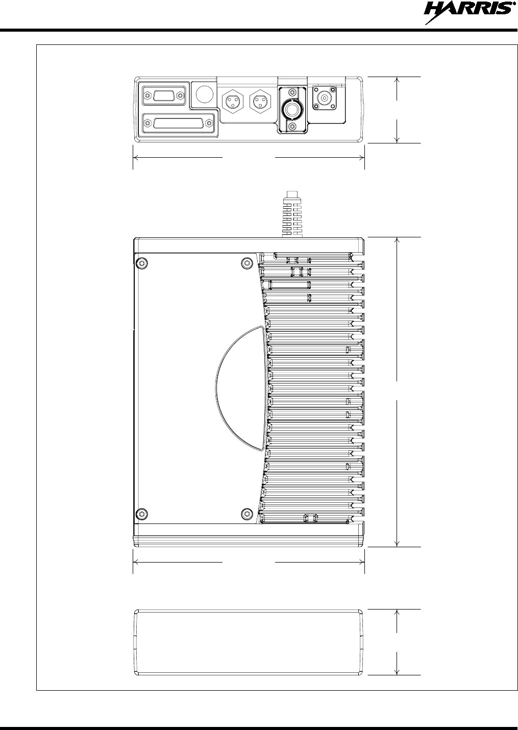
MM-014763-001, Rev. G
62
Figure 8-1: Remote-Mount M7300 Radio Dimensions
REAR VIEW
FRONT VIEW
2.0 inches
(51 mm)
2.0 inches
(51 mm)
6.9 inches
(175 mm)
6.9 inches
(175 mm)
TOP
VIEW
(Partial View of
DC Power Cable)
9.2 inches
(234 mm)
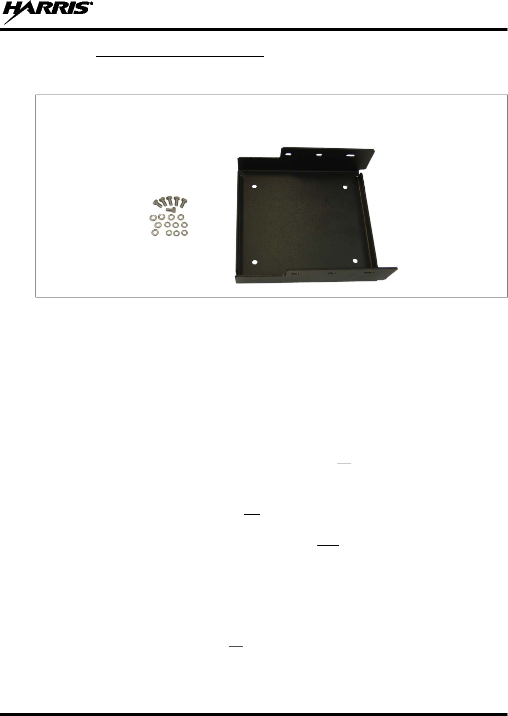
MM-014763-001, Rev. G
63
8.1.1 Mounting Bracket Installation
The remote-mount radio’s mounting bracket is included with the Remote-Mount Mounting Bracket Kit
KT23117. Kit contents are shown in Figure 8-2. This kit is Item 1 listed in Table 4-5 (page 29).
M5 Hardware for Mounting Bracket
Securing Radio FM103111V1
to Bracket
Figure 8-2: Remote-Mount Mounting Bracket Kit KT23117
Typically, the radio’s mounting bracket is mounted in the vehicle’s trunk, on the top surface of the trunk
tray or on the trunk floor. However, it can be suspended from the trunk’s rear deck if the surface is
completely flat and the thickness of deck’s sheet metal is adequate.
When selecting a mounting location for the radio, verify sufficient clearance can be maintained around
the radio for installation and service access. A minimum clearance of four (4) inches (approximately
10 centimeters) is recommended at the rear, left and right sides of the radio, and at least 2 inches
(approximately 5 centimeters) of clearance is recommended at the front of the radio.
As illustrated in Figure 8-3, the bracket is left-to-right symmetrical and the shortest portion of its side
rails are at the rear.
As installations differ, bracket-to-vehicle mounting screws are not included. Utilization of ¼-inch-
diameter, 28-thread-per-inch (¼-28) stainless-steel self-locking hardware (i.e., machine screws with
washers and locking nuts) is highly recommended. However, ¼-inch stainless-steel self-drilling screws
may be employed to speed installation time. Self-drilling screws such as “TEK” screws do not require
drilling of a pilot hole prior to installation. Do not use common self-threading sheet metal screws because
they will loosen over time with vehicle vibrations.
The bracket has four (4) available mounting holes. All four must be used to secure the bracket to its
mounting surface.
The following mounting procedure is recommended:
1. Using the mounting bracket as a template, and/or the dimensional information shown in Figure 8-3,
mark and drill four (4) mounting holes into the mounting surface as required per the type of hardware
used. When the radio is installed in the bracket, it will extend approximately one (1) inch past the
front edge bracket, and at the rear, it will extend approximately ½-inch past the rear edge of the
bracket. This distance at the rear does not include space required for cable connections at the rear of
the radio. As previously stated, a clearance of least four (4) inches (approximately 10 centimeters) at
the rear of the radio is recommended.
2. Temporarily remove the bracket and deburr all of the newly drilled holes.
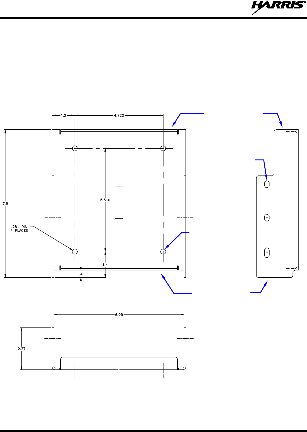
MM-014763-001, Rev. G
64
3. If necessary, apply an approved paint or rust-inhibitor at the holes in the mounting surface.
4. Set the bracket back into place, and verify front-to-rear orientation.
5. Install and tighten the mounting screws/hardware.
6. Verify the bracket is firmly secured to the mounting surface. A secure mount prevents unreasonable
vibration, which could damage the radio and/or cause its cable connections to loosen.
TOP VIEW SIDE VIEW
(Dimensions in Inches)
FRONT VIEW
(Dimensions in Inches)
(Made From FM103111 Rev. B)
Figure 8-3: Mounting Bracket FM103111V1 Dimensions
[for Remote-Mount M7300 Mobile Radio (Radio Not Shown)]
Bracket-To-Vehicle
Screw Holes
(4 places)
Bracket-To-Radio
Screw Holes
(6 places,
3 each side)
Rear of Bracket
Front of Bracket
MM-014763-001, Rev. G
65
8.1.2 Inserting the Radio into the Mounting Bracket
The radio should now be inserted into the bracket according to this procedure:
1. Lay the radio down into the mounting bracket with the front of the radio at the front of the mounting
bracket.
2. Attach the radio into the mounting bracket using the six (6) M5 x 10 mm stainless-steel hex-head
screws, and flatwashers and lockwashers included with the Mounting Bracket Kit (item 1 in Table
4-5). Tighten all six screws using a 5/16-inch wrench (or a ¼-inch-drive ratchet with a 5/16-inch socket)
until each lockwasher is fully compressed and the radio is firm and flush in between the brackets.
3. Check the mounting area for proper clearance for cable service looping and for air circulation, plus an
area to secure and stow the excess cable lengths.
Proper mounting is one factor that ensures optimal radio performance. An improperly
mounted radio m
ay experience degradation in the quality of voice and data
communications.
8.2 REMOTE-MOUNT RADIO’S DC POWER INSTALLATION
Unless otherwise noted, references in the following subsections to the “control head”
also apply to the hand-held controller.
8.2.1 Overview of On/Off Power Wiring Configurations
Radio on/off power control is accomplished by the control head, except in the case of a data-only radio
installation which has no control head. In a standard installation, when the control head is turned on, it
“wakes-up” the radio via data activity on the CAN link. The following power wiring configurations are
supported:
• Radio turns on and off automatically with vehicle’s ignition switch/key — This configuration
allows the on/off state of the vehicle’s ignition switch/key to control the on/off power state of the
radio. The white wire of the control head’s DC Power Cable is connected to a fused switched power
source, typically identified as vehicle “Accessory” power. This source must switch on (up to positive
(+) battery voltage potential) when the vehicle’s ignition switch/key turns on, and it must switch off
(to near zero volts) when the ignition switch/key turns off. The required fuse rating is 3 amperes.
When using this configuration, the CH-721 control head’s on/off/volume control must be left in the
on position for automatic power-up/down to function properly.
In a remote-mount radio installation, to fuse the white wire of the control head’s DC
Power Cable, a yellow waterproof (HFB type) fuse holder and a 3-amp AGC fuse are
included with the cable.
• Radio turns on and off with a manual switch — This configuration is used when, for example, the
radio must remain on even when the ignition key must be removed from the vehicle and a separate
on/off switch is acceptable. The white wire of the control head’s DC Power Cable is connected to one
side of a manually-controlled switch, and the other side of this switch is connected to unswitched and
fused vehicle power. The required fuse rating is 3 amperes. When using this configuration, the
CH-721 control head’s on/off/volume control must be left in the on position for automatic power-
up/down to function properly. This does not apply to the HHC-731 hand-held controller.
NOTE
NOTE
NOTE
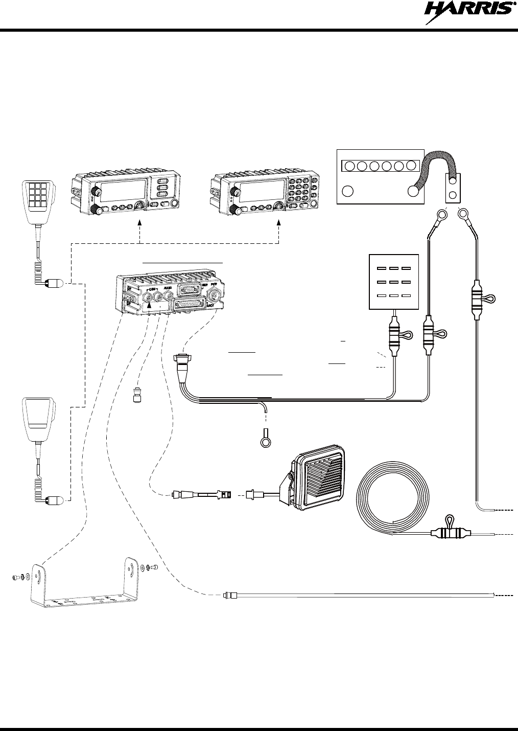
MM-014763-001, Rev. G
66
Figure 8-4: Wiring Diagram for a Remote-Mount Radio Installation
CH-721 SCAN MODEL
CONTROL HEAD
CU23218-0002
(MAMW-NCP9E)
CH-721 SYSTEM MODEL
CONTROL HEAD
CU23218-0004
(MAMW-NCP9F)
DTMF
MICROPHONE
MC-103334-040 OR
MC-103334-041
(INCLUDED WITH
MAMW-NMC9C)
STANDARD
MICROPHONE
MC-101616-040 OR
MC-101616-041
(INCLUDED WITH
MAMW-NMC7Z)
OR
NOISE-CANCELING
MICROPHONE
MC-103334-050 OR
MC-103334-051
(INCLUDED WITH
MAMW-NMC9D)
CH-721 MOUNTING
BRACKET KIT
KT-008608
[SUPPLIED WITH
INSTALLATION KIT]
• IF IGNITION SENSE ON/OFF FUNCTIONALITY IS REQUIRED,
CONNECT WHITE WIRE OF CONTROL HEAD’S DC POWER CABLE
TO A SWITCHED 13 VDC POWER SOURCE USING THE SUPPLIED
FUSE AND FUSE HOLDER.
• IF IGNITION SENSE ON/OFF FUNCTIONALITY IS NOT REQUIRED,
CONNECT WHITE WIRE OF CONTROL HEAD’S DC POWER CABLE
TO AN UNSWITCHED 13 VDC POWER SOURCE USING THE
SUPPLIED FUSE AND FUSE HOLDER.
WATERPROOF CAP
FM-104859-001 (NOT SHOWN)
FOR DB-9 SERIAL CONNECTOR
[SUPPLIED WITH INSTALLATION KIT]
WATERPROOF CAP
FM-104859-002 (NOT SHOWN)
FOR DB-25 ACCESSORY CONNECTOR
[SUPPLIED WITH INSTALLATION KIT]
REAR VIEW OF CONTROL HEAD
NEG POS
3-AMP FUSE &
FUSE HOLDER
(HFB TYPE) RED
RED RED
5-AMP
FUSE
& FUSE
HOLDER
(HFB TYPE)
3-AMP FUSE &
FUSE HOLDER
(HFB TYPE)
15-AMP
FUSE &
FUSE
HOLDER
(HFB
TYPE)
RED
WHITE
RED
RING
TERMINALS
VEHICLE
DC POWER
DISTRI-
BUTION
BLOCK
(E.G.,
“POWER
ACCESS
POINT”)
VEHICLE BATTERY
+-
NOTE: BATTERY GROUND (-)
CONNECTION NOT INDICATED.
CAN
TERMINATOR
CD-014027-001
[SUPPLIED
WITH
INSTALLATION
KIT]
RED
WHITE
BLACK
(SHORT AS POSSIBLE)
RING TERMINAL
(CONNECT TO VEHICLE
CHASSIS GROUND)
CAN CABLE CA-009562-030 (30 FEET LONG) [SUPPLIED WITH INSTALLATION KIT]
SPEAKER CABLE
MAMROS0034-NN006
[SUPPLIED WITH
INSTALLATION KIT]
EXTERNAL SPEAKER
LS102824V10
[SUPPLIED WITH
INSTALLATION KIT] WHITE WIRE OF RADIO’S DC
POWER CABLE (LABELED
AND COILED NEAR
VEHICLE’S FUSE BOX)
DC POWER CABLE CA-012616-001
(SUPPLIED WITH INSTALLATION KIT)
VEHICLE FUSE
BOX, ETC.
WHITE
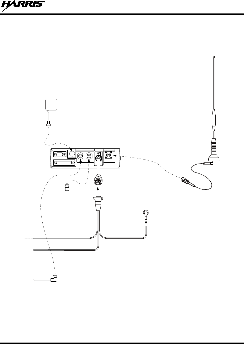
MM-014763-001, Rev. G
67
GPS ANTENNA
(OPTIONAL; SEE TEXT FOR
SPECIFIC PART NUMBERS)
DC POWER CABLE
CA-012365-001
(SUPPLIED WITH
INSTALLATION KIT)
RING TERMINAL
(CONNECT TO VEHICLE
CHASSIS GROUND)
BLACK
BLACKRED
WHITE
M7300 MOBILE RADIO
VHF RADIO = RU-144750-041;
UHF-L RADIO = RU-144750-021;
UHF-H RADIO = RU-144750-031;
700 & 800 MHz RADIO = RU-144750-061
REAR VIEW
MOBILE
ANTENNA
(OPTIONAL;
SEE TEXT
FOR
SPECIFIC
PART AND
OPTION
NUMBERS)
MALE TNC RF
CONNECTOR
(SUPPLIED WITH
ANTENNA)
CAN TERMINATOR
CD-014027-001
[SUPPLIED WITH
INSTALLATION KIT]
Figure 8-4: Wiring Diagram for a Remote-Mount Radio Installation (Cont.)
MM-014763-001, Rev. G
68
• Radio turns on with control head’s on/off/volume control (“hot wired”) — This configuration
allows radio on/off power control only via the control head’s on/off/volume control. It may be desired
if, for example, the radio must remain on even when the ignition key must be removed from the
vehicle and a separate on/off switch is not desired and/or not acceptable. The white wire of the
control head’s DC Power Cable must be connected to unswitched and fused vehicle power. The
required fuse rating is 3 amperes.
In all of the above cases, both the radio’s main DC power input (red wire) and the control head’s main
DC power input (also a red wire) must each be connected through an in-line fuse to unswitched vehicle
DC power. The red wire of the radio’s DC Power Cable must be connected to raw battery power (positive
battery terminal) via the supplied fuse. Likewise, the red wire of the control head’s DC Power Cable must
also be connected to unswitched vehicle DC power via another supplied fuse. The white ignition wire of
the radio’s DC Power Cable is only used for the data-only radio (i.e., no control head), and it is the only
means for turning its power on in the data-only radio installation.
Any DC input power
provided to the radio shall be no higher or lower than
13.6 volts DC ±10%. The DC input power should be free and clear of any AC noise or
DC spikes above 18 volts. If the vehicle
cannot meet these requirements, then DC
conditioning will be required before any DC power is connected to the radio. This
includes conditioning for both the radio’s main DC power input lead and for its
switched ignition sense power input. DC conditioning can be accomplished by a noise
filter or DC isolation equipment such as Harris part number FL-018314-001 or FL-
018314-002, or similar units with equal specifications. The fuse must be placed in-line
before any noise filter. Contact TAC for additional information.
8.2.2 DC Power Cable and Main Fuse Holder Installation
The radio’s DC Power Cable has a 3-pin connector, a 20-foot red wire (for the main power connection), a
20-foot white wire (only connected in a data-only radio installation), and a 4-foot black wire (for the
ground connection). It is supplied with waterproof fuse holders, two AGC-type fuses, and non-insulated
ring terminals. The following installation procedures are recommended:
8.2.2.1 Black Wire Connection (Ground Wire)
1. Connect the radio’s DC Power Cable to the radio by mating its 3-pin connector to the radio’s 3-pin
power cable connector as follows: Visually align the key and firmly push and turn the outer locking
ring clockwise until it stops. A click will be sensed to confirm proper mating.
Do not confuse the radio’s DC Power Cable which has a 10-AWG red wire with the
control head’s DC Power Cable which has a 12-AWG red wire. The radio requires
much more DC operatin
g current than the control head. Therefore, it requires the
larger wire size of 10-AWG. The part number of the radio’s DC Power Cable is
CA-012365-001.
2. Prepare to connect the cable’s black wire to vehicle ground by locating an area of vehicle metal
within approximately two (2) feet of the radio. This surface must have a solid and stable connection
to vehicle ground. If not, add grounding strap(s) as necessary.
3. Strip the area of any paint or dirt to expose a bare metal surface, approximately ¾-inch square.
4. Drill a hole in the approximate center of the bare metal surface, and deburr it. A ⅜-inch non-
insulated ring terminal is supplied with the cable to make this ground connection. Therefore, hole
CAUTION
CAUTION
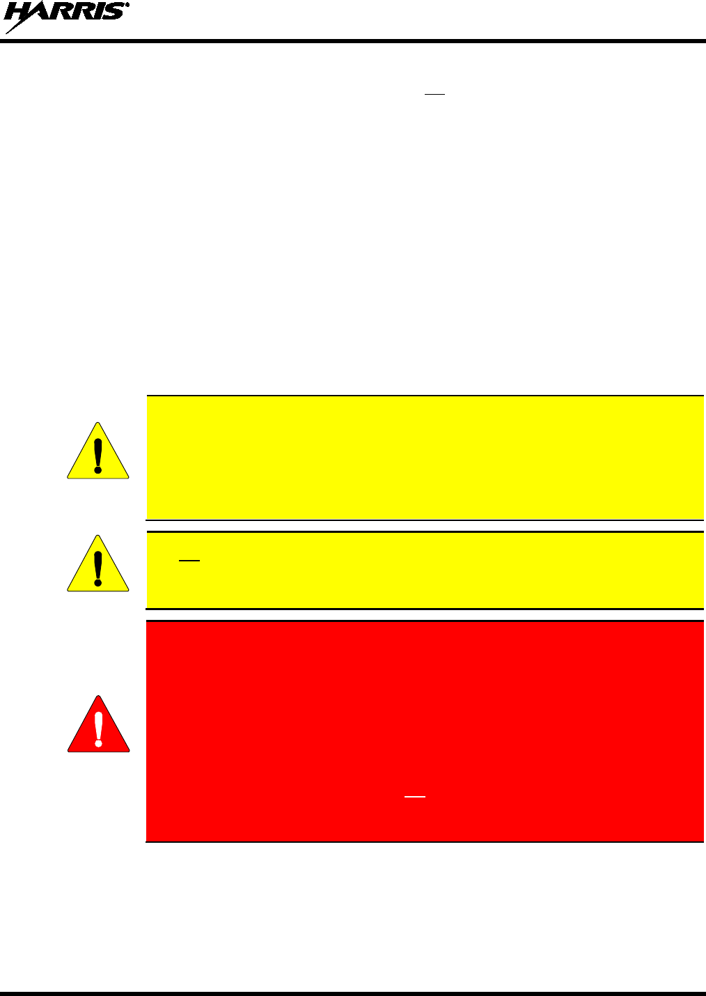
MM-014763-001, Rev. G
69
diameter should be appropriate for the utilized grounding screw/bolt size and type used to connect the
ring terminal to the bare metal surface. This hardware is not supplied.
5. Cut the black wire to the required length plus some additional length for a service loop, then strip
insulation back approximately ¼-inch.
6. Crimp a ⅜-inch non-insulated ring terminal (supplied with the cable) to the end of the black wire.
7. Attach the ring terminal and black wire to the bare metal surface using stainless-steel self-locking
hardware (i.e., machine screws with washers and locking nuts) or other appropriate hardware to
ensure a reliable terminal-to-metal contact. Tighten securely.
8. Apply an approved paint or rust-inhibitor over the remaining exposed bare metal surface and around
the ring terminal.
8.2.2.2 Red Wire and Main Fuse Holder Connection (Radio’s Main Power Wire)
1. Continue installation of the radio’s DC Power Cable by routing its 20-foot 10-AWG red wire to the
location of the vehicle’s battery (or its main DC bus bar or stud). Remove interior panels, door kick
panels, etc., and route the wire through existing channels in the vehicle body as necessary. Protect the
wire from possible chafing where necessary. Tie and stow the wire as necessary.
Plan the routing of the 10-AWG red wire carefully, using an existing access hole in the
vehicle’s firewall if possible. Alternately, drill a new hole approximately ⅜-inch in
diameter and install a small rubber grommet to protect the wire from chafing on the
hole’s sharp metal edge.
To prevent fumes from entering the passenger
compartment, this hole/grommet/wire combination must also be sealed with a
silicon-based sealer before completing the installation.
Do not install any wiring or fuse holder over or in the near vicinity of the vehicle’s
engine. Excessive engine heat can cause permanent damage to these components and
can lead to intermittent electrical connection to the battery.
Before making connections to the battery’s positive post, carefully disconnect the
battery’s
negative (ground) cable(s). This will prevent tools or other metallic
objects which come in contact with the battery’s positive terminal from shorting to
vehicle ground, causing sparks or even a fire or an explosion! When disconnecting
the negative cable(s
), cover/insulate the positive post(s) if it is not already so a tool
cannot short between the posts. Some vehicles, such as those with diesel engines
have more than one battery; in this case, disconnect the negative cables at all
batteries.
Radio and control head fuses should not
be installed until all wiring is complete.
This will prevent the radio from powering up prematurely and/or causing an in-
rush of current that could lead to shorting of the battery, sparks, or even fire.
2. Obtain the orange waterproof (HFB type) fuse holder included with the DC Power Cable.
3. Observe and follow the previously presented WARNING!
4. Cut the red wire to the required length for connection to the battery’s positive (+) battery terminal (or
the main DC bus bar or stud).
CAUTION
CAUTION
WARNING
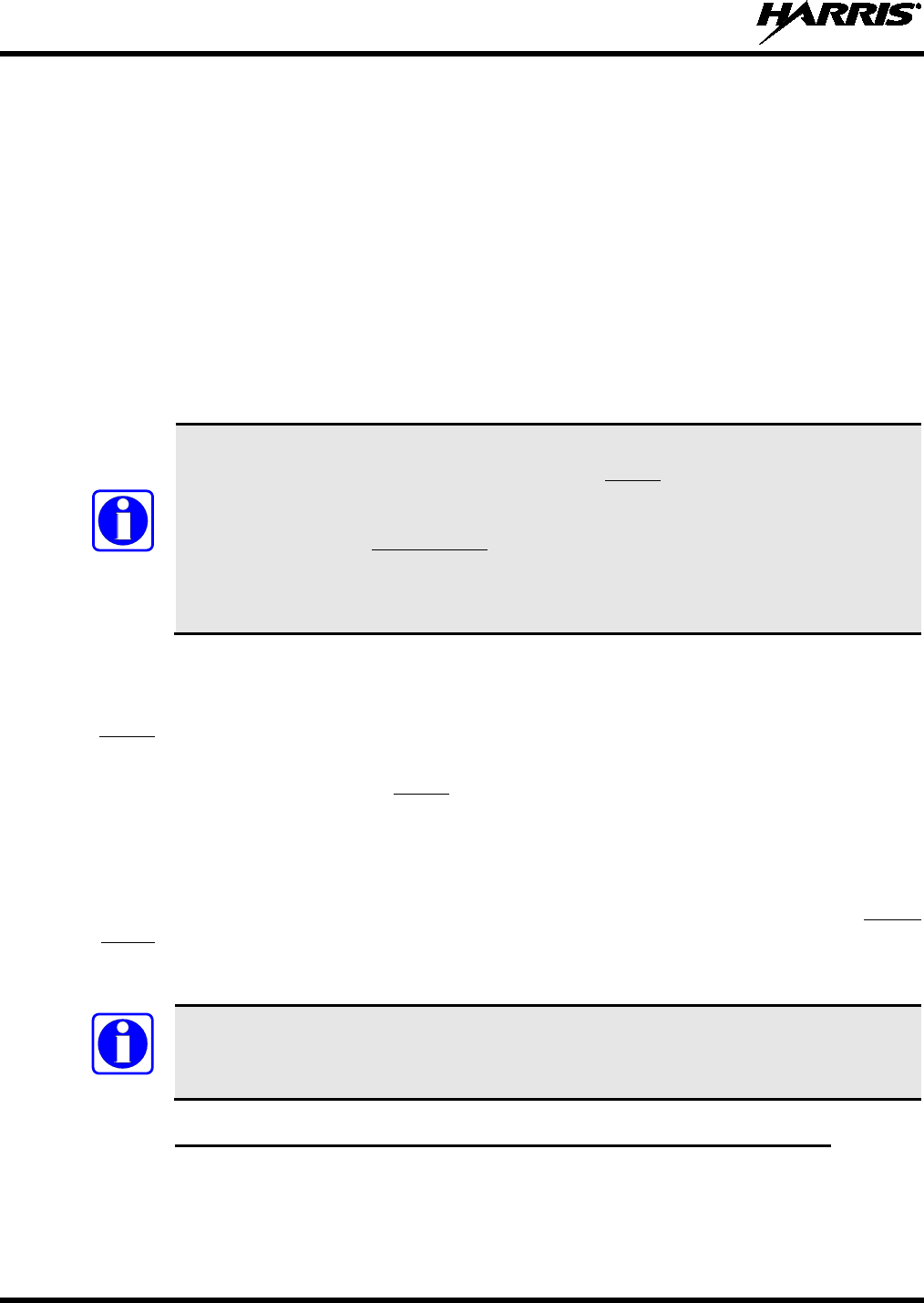
MM-014763-001, Rev. G
70
5. Prepare to splice the waterproof fuse holder into the red wire by cutting it again, at approximately
three (3) to six (6) inches from the end.
6. Strip all three (3) wire ends back approximately ⅜-inch each, place a fuse holder shell on each wire,
and securely crimp a fuse holder terminal to each wire end. Before crimping, verify fuse holder shells
are oriented in the correct directions (i.e., with each large end towards the wire end).
7. Label this fuse holder and red wire appropriately (e.g., “M7300 Main Power: 15-AMP FUSE”).
8. Do NOT install a fuse into the fuse holder at this time.
9. Crimp an appropriate electrical terminal to the short red wire. A corrosion-resistant ⅜-inch ring
terminal is included with the cable for this purpose, but another size corrosion-resistant terminal type
(not supplied) may be used if required.
10. Connect the ring terminal directly to the battery’s positive post (or if present, to a stud on the battery’s
main/non-switched power distribution terminal block).
Most M7300 radio installations have one or more control heads connected to the radio. In
an installation of this type, the white wire of the radio’s
DC Power Cable requires no
electrical connection. Rather than be cut from the cable, it is recommended that it be
routed up to the vehicle’s fuse box, coiled, labeled, and stowed for possible future use.
The white wire of the control head’s
DC Power Cable is the radio installation’s ignition
sense input for on/off power control of both the control head and radio. Radio on/off
power control is accomplished by the control head. The control head “wakes-up” the radio
via data activity on the CAN link.
8.2.2.3 White Wire Connection (for Data-Only Radio Installations)
In the case of a data-only radio installation (i.e., no control head connected to the radio), the white wire of
the radio’s DC Power Cable is used as the radio installation’s ignition sense input. Therefore, it requires
electrical connection to a fused switched power source. The following procedure is recommended:
1. Route the 20-foot white wire of the radio’s DC Power Cable to the location of the vehicle’s switched
power source connection point, typically identified as “Accessory” power. Remove interior panels,
door kick panels, etc., and route the wire through existing channels in the vehicle body as necessary.
Protect the wire from possible chafing where necessary. Tie and stow the wire as necessary.
2. Connect this white wire through a fuse to the switched power source in accordance with the
instructions presented within the respective subsection of Section 8.3.4.2 (page 77) for the control
head’s white wire. Follow the procedure in Section 8.3.4.2.1 (page 77) if the vehicle’s ignition
switch/key must control the data-only radio’s on/off power. Follow the procedure in Section 8.3.4.2.2
(page 78) if a manually-controlled switch must control the data-only radio’s on/off power.
The “hot wired” wiring configuration (as depicted in Section 8.3.4.2.3) cannot be utilized
for the data-only radio, since this configuration does not employ the DC Power Cable’s
white wire.
8.2.3 Additional Hook-Up Required for a Data-Only Radio Installation
The CTLON (control power on) logic input of a data-only radio must be grounded per this procedure:
1. Obtain M5300/M7300 Option Cable CA-012349-001.
2. Connect this cable’s male DB-44 connector to the female DB-44 connector on the rear of the radio.
Tighten the connector’s two (2) jackscrews firmly.
NOTE
NOTE
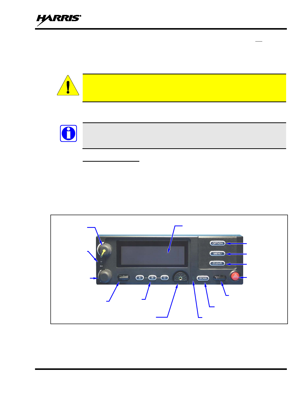
MM-014763-001, Rev. G
71
3. Using an appropriate DB-25 connector, hook-up wire, ring terminal and hardware (not supplied),
connect pin 14 of this cable’s DB-25 connector (P4 pin 14) to vehicle ground. This grounds the
radio’s CTLON input at pin 15 of the DB-44 connector. See Section 11.1 for additional information
on the Option Cable. Keep the length of the ground wire as short as reasonably possible.
4. Tie and stow the cable and wire as necessary to protect them from possible cable chafing.
When servicing the radio and/or control head, always manually power-down the radio
equipment via the control head’s on/off/volume control knob, and then remove the main
power fuse near the battery.
8.3 CH-721 CONTROL HEAD INSTALLATION
This section includes installation instructions for the CH-721 control head. If the radio is
being installed with and connected to an HHC-731 hand-held controller, skip this section
and advance to Section 8.4 which begins on page 80.
8.3.1 General Information
The remote-mount M7300 mobile radio must be connected to a control head to provide the operator-to-
radio interface. Two different control heads are available — the CH-721 Scan model and the CH-721
System model. See Figure 8-5 and Figure 8-6 respectively. The CH-721 Scan model control head features
three (3) large menu selection buttons. The System model control head has a 12-button keypad to allow
advanced operations without the need of a DTMF-capable microphone.
Figure 8-7 on page 72 illustrates the rear panel of the two control head models. Both models have
identical rear panels and rear panel connectors.
Figure 8-5: CH-721 Scan Model Control Head Front Panel
CAUTION
NOTE
3-Line Graphical Vacuum
Fluorescent Display
Microphone Connector
On/Off/
Volume
Control
System/-
Group/-
Channel
Selection
Control
•/•• Ramp Control
Preset/
Softkey
Buttons
Emergency/
Home Button
+/- Ramp Control
Ambient Light-Level Sensor
Transmit
and Busy
Indicators
Scan On/Off Button
Clear Button
Menu Button
Option Button
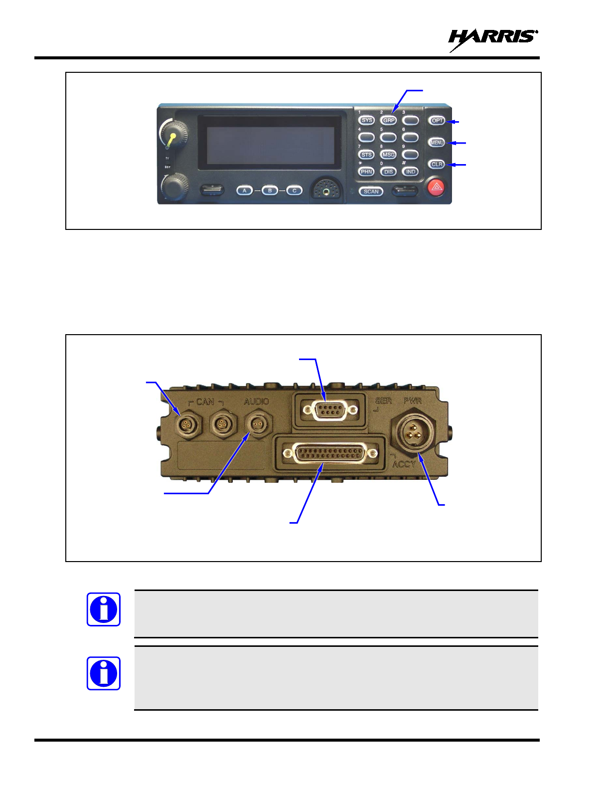
MM-014763-001, Rev. G
72
(Other controls are same as shown for Scan model.)
Figure 8-6: CH-721 System Model Control Head Front Panel
The CH-721 control heads feature a large easy-to-read 3-line graphical vacuum fluorescent display, an
on/off/volume control knob, menu controls and buttons, trunking mode buttons, an emergency/home
button, a scan on/off button, and three (3) preset buttons. Other front panel components include a
microphone connector and LED-type indicators. One LED indicator is the busy indicator that lights when
the radio is receiving a call and one is the transmitter-enabled indicator that lights when the radio is
transmitting. The front panel also has an ambient light sensor for automatic display dimming.
Figure 8-7: CH-721 Rear Panel (both control head models)
Prior to installing the control head, verify it has the proper software version installed and
verify it has been properly configured for customer use.
Because Installation Kit MAMW-NZN7R contains the most complete set of materials for
installing the radio and control head, the following instructions make repeated reference
to items within this kit. Item numbers given in parenthesis refer to items in the kit as
listed in Table 4-5 on page 29.
NOTE
NOTE
12-Button Keypad
Clear Button
Menu Button
Option Button
CAN Port
Connectors
(2 places)
Speaker Audio
Connector
Serial Port Connector
(DB-9)
DC Power
Connector
Accessory Connector
(DB-25)
Note: Serial and Accessory connectors are
shown without waterproof covers.
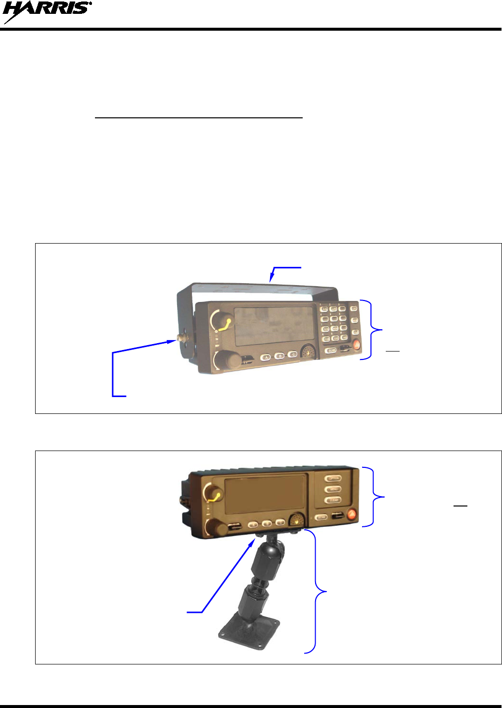
MM-014763-001, Rev. G
73
In a mobile installation, more than one control head can be connected to one mobile radio for multi-head
installations. A multi-head installation may be required in a vehicle such as a fire truck or any large
vehicle where more than one operator may require use of the radio. Multi-head installations also provide
other benefits such as intercom functionality between different operator positions.
8.3.2 Control Head Mechanical Installation
8.3.2.1 Selecting the Mounting Location
When selecting a location for the CH-721 control head, first observe the safety and operator-convenience
related information presented in Section 5.1 on page 37. Always consider and include clearance for the
microphone’s connector that must mate to the mic connector on the front panel of the head, and clearance
for the connectors/cables that must mate to the connectors on the rear panel of the head. The CH-721
control head can be mounted under or on top of a mounting surface (typically the vehicle’s dash) as space
permits using either the standard U-shaped mounting bracket or the optional mounting pedestal.
Figure 8-8: Standard U-Shaped Control Head Mounting Bracket (Kit Part Number KT-008608)
Figure 8-9: Optional Control Head Mounting Pedestal (Part Number MACDOS0012)
Mounting Bracket (Shown
positioned above control head)
Control Head Mounting
Pedestal MACDOS0012
(Pedestal can be attached to the
bottom of the head (as shown) or it
can be attached to the top of the
head.)
Bracket shown
attached to a CH-721
System model
control head (Head is
not included with
Mounting Bracket Kit)
Pedestal shown
attached to a CH-721
Scan model control
head (Head is not
included with Mounting
Pedestal.)
Socket-Head Cap (Allen) Screw, Lockwasher and Flat
Washer; 2 places each side (Included with kit)
#8-32 Pan-Head Screw; 4
places
(Included with
Mounting Pedestal)
For a “hanging” control head
installation, the pedestal can
be attached to the top of the
head via threaded holes in
the top of the head’s
case.
This figure shows the
pedestal attached to the
bottom of the control head via
threaded holes in the bottom
of the case.
MM-014763-001, Rev. G
74
8.3.2.2 Using the Standard U-Shaped Mounting Bracket
If the standard U-shaped mounting bracket will be used to mount the control head, the following
mounting procedure is recommended. As listed in Table 4-5 on page 29, this bracket is item 2 in the
Installation Kit.
1. Using the mounting bracket as a template, mark and drill mounting holes into the mounting surface as
required. The round and elliptical holes in the bracket’s vehicle mounting surface are symmetrical, so
forwards/backwards positioning is not important during this step. However, positioning is important
in the next step.
Before drilling holes and/or installing mounting screws, verify these operations will not
damage or interfere with any existing vehicle component (the fuel tank, a fuel line, the
transmission housing, existing vehicle wiring, etc.). Always check to see how far the
mounting screws will extend below the mounting surface prior to installation. Always
deburr drilled holes before installing screws.
2. Postion the bracket at the mounting surface so the two round holes in its two side “ears” are nearest to
the normal location of the operator (typically towards the rear of the vehicle) and the two slotted holes
are furthest from the normal location of the operator (typically towards the front of the vehicle).
3. Install and tighten the mounting screws. Screws for mounting the bracket to the mounting vehicle’s
surface are not included, as all installations differ. Self-threading screws are recommended. Use of
self-drilling screws may cause damage to some mounting surfaces, such as a plastic dash panel.
4. Verify the bracket is held firmly to the mounting surface. Firm mounting prevents unreasonable
vibration, which could damage the control head and/or cause its cable connections to loosen.
5. Slide the control head into the bracket, placing the two pegs protruding from its left and right sides
into the respective round holes in the bracket’s two side “ears.”
6. In each side “ear” of the mounting bracket, start a #8-32 hex-socket-head cap (Allen) head screw with
a lockwasher and a flat washer by inserting the screw through the slotted hole in the bracket and then
into the threaded hole in the side of the control head. This hardware is included with Mounting
Bracket Kit. The lockwasher should be adjacent to the screw head and the flat washer should be
adjacent to the bracket. Turn each screw clockwise as observed from the head of the screw.
7. The control head can be positioned at various angles for best display viewing at the normal position
of the operator. As necessary, turn it on the pegs to a good position and tighten both screws using an
⅛-inch hex key (Allen) wrench until the control head is held firmly in place. Do not over-tighten.
8.3.2.3 Using the Mounting Pedestal (Optional)
An optional Mounting Pedestal, part number MACDOS0012, may be purchased separately to replace the
standard U-shaped mounting bracket. This pedestal can be attached to the bottom of the control head as
shown in Figure 8-9, and then mounted to a mounting surface below the two. It can also be attached to the
top of the head and then mounted to a mounting surface above the two.
8.3.3 Control Head-to-Radio CAN Cable Connections
8.3.3.1 General Information
A remote-mount radio installation requires a CAN cable between every two “CAN devices” and CAN
terminators on each end of the CAN link. The M7300 mobile radio is considered a CAN device, and each
CH-721 control head in the installation is also considered a CAN device. Figure 8-10 illustrates CAN
CAUTION
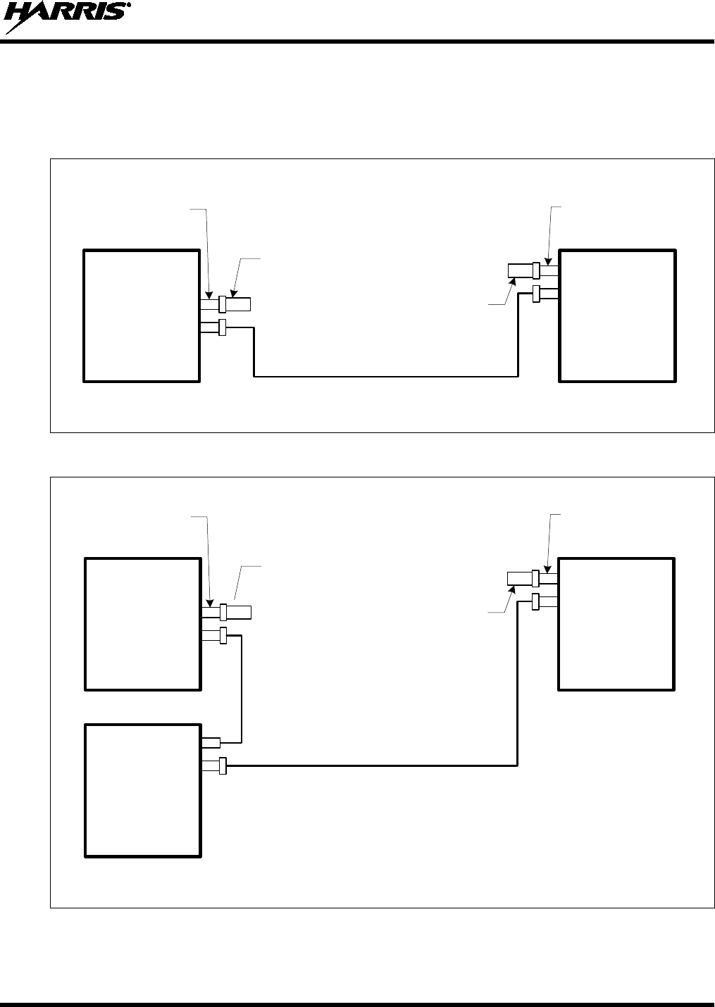
MM-014763-001, Rev. G
75
cable and CAN terminator connections for a single control head installation. Figure 8-11 illustrates this
for a multi-head control head installation where, for example, one control head is located at the main
operator location and another is located near the rear of the vehicle. Because CAN devices do not have
internal terminators, the CAN link must be terminated at both ends via external CAN terminators, as
depicted in the following figures.
CAN Terminator CD-014027-001
(for radio end)
CH-721
Control
Head
CAN Cable CA-009562-nnn
(where nnn specifies cable length in feet)
CAN Terminator CD-014027-001
(for control head end)
CAN
3-Pin CAN Port
Connectors on
Rear of Radio
(2 places)
CAN
CAN
M7300
Mobile
Radio
CAN
3-Pin CAN Port
Connectors on Rear
of Control Head
(2 places)
For Available CAN Cable Lengths and Respective Part Numbers, see Table 4-8 on page 36.
Figure 8-10: CAN Link Connections for a Single Control Head Installation
CAN Cable CA-009562-nnn
(where nnn specifies cable length in feet)
NOTE: The M7300 mobile radio may be located in the middle of the CAN link. For a
2-head installation, two CAN cables would connect directly to the two CAN port
connectors on the rear of the radio, and each CH-721 control head would require a
CAN terminator. When the radio is in the middle of the CAN link, no CAN terminator
is required at the radio.
CAN Terminator CD-014027-001
(for radio end) CH-721
Control
Head #1
(e.g., at main
operator location)
CAN Cable CA-009562-nnn
(where nnn specifies cable length in feet)
CAN Terminator CD-014027-001
(for control head end)
CAN
3-Pin CAN Port
Connectors on
Rear of Radio
(2 places)
CAN
CAN
M7300
Mobile
Radio
CAN
3-Pin CAN Port
Connectors on Rear
of Control Head
(2 places, this head)
CAN
CAN
CH-721
Control
Head #2
(e.g., near rear of
vehicle)
For Available CAN Cable Lengths and Respective Part Numbers, see Table 4-8 on page 36.
Figure 8-11: Typical CAN Link Connections for a Multi-Control Head Installation
Both the radio and the control head have two CAN ports to support “daisy-chaining” of multiple control
heads or other CAN devices. Figure 5-3 on page 39 shows the radio’s two CAN port connectors, which
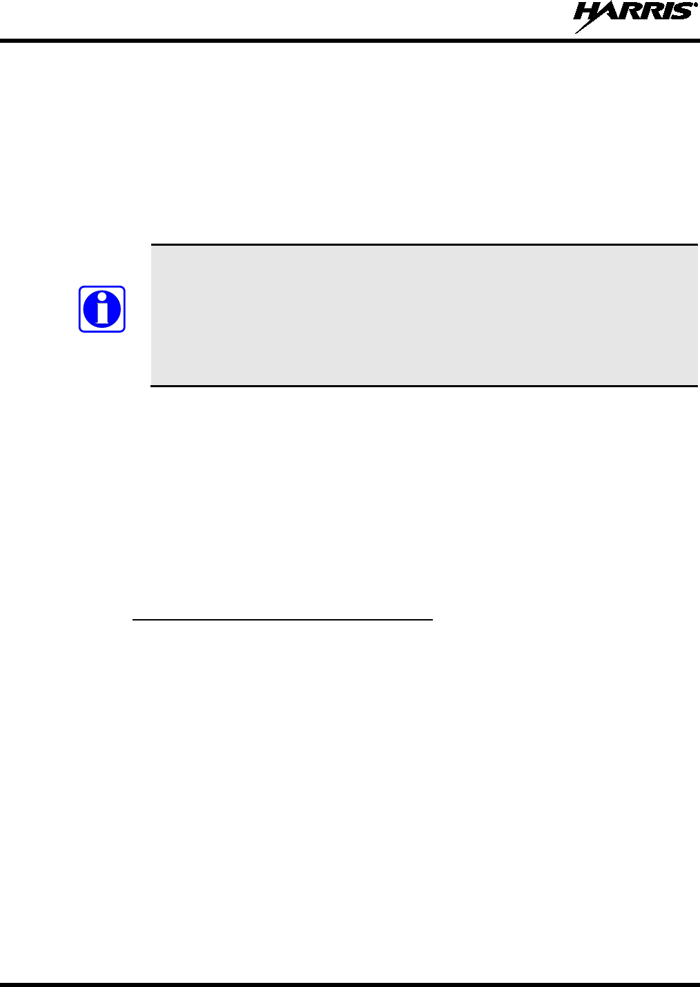
MM-014763-001, Rev. G
76
are located near the center of the radio’s rear panel. Figure 8-7 on page 72 shows the two CAN port
connectors on the control head’s rear panel.
8.3.3.2 Make CAN Link Terminations and Cable Connection
Follow this procedure for an installation which has only one control head. For a multi-control head
installation, refer to Figure 8-11 as necessary.
1. Mate a CAN Terminator (item 5 in Table 4-5 on page 29) with either one of the two smaller 3-pin
CAN port connectors on the rear panel of the CH-721. This action makes the CAN termination at the
control head end of the CAN link.
When mating any CAN connection (terminators and cables) to a rear panel connector,
visually align the ¾-moon-shaped keys of the connectors, and then gently push and
turn the outer locking ring of the plug (male) connector clockwise until it stops. A mild
click will be sensed to confirm proper mating. Without visual alignment as a guide, it
is possible with excessive force t
o mate the CAN connectors improperly. Damage to
the connector(s) may result. Therefore, visual alignment is recommended when mating
CAN connectors.
2. Obtain a CAN Cable and mate it to the other CAN port connector on the rear panel of the CH-721.
Typically, item 6 in Table 4-5 is utilized, a 30-foot CAN cable.
3. Route the cable through the vehicle’s interior wire/cable channeling to the radio. Remove interior
panels, door kick panels, etc., as necessary. Protect the cable from possible chafing as necessary.
4. Mate this other end of the cable to one of the two CAN port connectors on the rear panel of the radio.
5. Mate another CAN Terminator to the other CAN port connector on the rear panel of the radio. This
action makes the CAN termination at the radio-end of the CAN link.
6. Loop, tie and stow the excess cable as necessary, leaving a service loop at the back of the radio and at
the back of the control head.
8.3.4 Control Head Power Cable Installation
Plan the route of the control head’s DC Power Cable carefully. Do not route the cable where it will be
damaged by heat sources or by casual contact, and protect it from wire chafe per standard installation
methods. The following procedures are recommended:
8.3.4.1 Install DC Power Cable and Make Power and Ground Connections
1. Connect the control head’s DC Power Cable (item 4 in Table 4-5 on page 29) to the large 3-pin
connector at the rear of the head. Visually align the key and gently push and turn the outer locking
ring clockwise until it stops. A click will be sensed to confirm proper mating.
2. At the back of the control head, locate a nearby section of vehicle chassis ground and strip this area of
any paint or dirt to expose a bare metal surface.
3. Cut the black wire of the control head’s DC Power Cable to the required length, plus a service loop of
at least six (6) inches, then strip it and crimp a ⅜-inch ring terminal to it. Two ring terminals of this
type are included with the cable.
4. Drill a hole as necessary and attach this ring terminal to chassis ground. Use stainless-steel self-
locking hardware (i.e., machine screws with washers and locking nuts) or other appropriate hardware
to ensure a reliable terminal-to-metal contact. Tighten securely.
NOTE
MM-014763-001, Rev. G
77
5. At the back of the control head, tie and stow the cable as necessary.
6. For the positive 12-volt DC main power source connection, route the cable’s red wire to the location
of an unswitched 12-volt DC power source, typically near the vehicle’s battery. Remove interior
panels, door kick panels, etc. Protect the wire from possible chafing as necessary. This is the control
head’s main DC power source.
7. Obtain one of the yellow waterproof (HFB-type) fuse holders included with the control head’s DC
Power Cable.
8. Cut excess length from the red wire and splice the fuse holder into it, near the location of the
unswitched 12-volt DC power source connection point.
9. Using an appropriate electrical terminal, connect the red wire to the unswitched DC power source. A
⅜-inch ring terminal is included with the cable for this purpose, but another terminal type (not
supplied) may be used if required.
10. Obtain the 5-amp AGC-type fuse included with the cable, and install it into the fuse holder.
Do not share the control head’s fuse with any other device. Doing so can cause excess
current to flow through the fuse, causing it to blow unnecessarily.
The fuse for the control head’s red wire is rated at 5 amperes. The 3-amp fuse included
with the cable must not be used for fusing the control head’s main DC power. It fuses
the head’s white wire.
8.3.4.2 Connect DC Power Cable’s White Wire
A review of the information presented in Section 8.2.1 (page 65) may be beneficial at this time. As
required per the chosen power-up configuration, connect the white wire by following one of the three
procedures presented in the respective sub-section that follows.
8.3.4.2.1 Control Head and Radio Turn on with Vehicle’s Ignition Switch/Key
With this wiring configuration, the control head and radio automatically turn on and off with the vehicle’s
ignition switch/key. The white wire of the control head’s DC Power Cable is sometimes referred to as the
“white ignition switch wire” or the “ignition sense input wire.” In this configuration, the white wire
connects to a switched power source, typically identified as “Accessory” power, that switches on and off
with the vehicle’s ignition switch/key. When using this configuration, the CH-721 control head’s
on/off/volume control must be left in the on position for automatic power-up/down to function properly.
The white ignition sense wire must be connected to a fused power source that switches
from approximately zero volts to approximately +13.6 volts when the vehicle’s ignition
switch/key is turned from the OFF position to the ACCESSORY and RUN positions.
Use of a switched power source that is subject to voltage changes as a result of other
actions, such as opening a vehicle door, may result in undesirable radio power cycles.
1. Locate the vehicle’s switched ignition or “Accessory” power connection point that will be used for
the switched ignition 12-volt DC power source. This point is typically located at or near the vehicle’s
fuse panel. It may be necessary to consult the vehicle manufacturer’s wiring diagram.
NOTE
CAUTION
NOTE

MM-014763-001, Rev. G
78
2. Route the white wire of the control head’s DC Power Cable from the back of the head to the area near
this connection point. Protect the wire from possible chafing as necessary.
3. Obtain one of the yellow waterproof (HFB-type) fuse holders included with the control head’s DC
Power Cable.
4. Cut excess length from the white wire and splice the fuse holder into it, near the location of the
connection point.
5. Using an appropriate electrical terminal, connect the white wire to the switched power connection
point. An open-barrel spade terminal is included with the cable for this purpose, but another type of
terminal (not supplied) may be used as required.
6. Obtain the 3-amp AGC-type fuse included with the cable, and install it into the fuse holder.
7. Tie and stow all wiring as necessary so it remains out of the way of casual contact and wire chafe is
avoided.
8.3.4.2.2 Control Head and Radio Turn On with a Manual Switch
With this wiring configuration, the control head and radio are manually turned on and off via an on/off
switch mounted separately from the control head and radio, not through the vehicle’s ignition switch/key.
This configuration is used when, for example, the radio must remain on even when the ignition key must
be removed from the vehicle and a separate on/off switch is acceptable and/or required. In this
configuration, the white wire connects to a fused switched power source such as that provided by a toggle
switch mounted on the vehicle’s dash panel. When using this configuration, the CH-721 control head’s
on/off/volume control must be left in the on position for automatic power-up/down to function properly.
1. Route the white wire of the control head’s DC Power Cable from the back of the head to an area near
the location of the panel-mounted on/off switch. Protect the wire from possible chafing as necessary.
2. Cut a short section (6 to 8 inches) off the end of the white wire and strip the ends.
3. Obtain one of the yellow waterproof (HFB-type) fuse holders included with the control head’s DC
Power Cable, and crimp one half of it to one end of the short section of wire.
4. Using an appropriate electrical terminal, connect this short white wire to unswitched 12-volt DC
power source at or near the vehicle’s fuse box.
5. Cut another section of white wire from the cable. This wire must be long enough to reach from this
fuse holder to the location of the panel-mounted on/off switch.
6. Strip one end of this wire and crimp the other half of the waterproof fuse holder to this wire end.
7. Strip the other end of this wire and, using an appropriate electrical terminal, connect it to the common
terminal of the switch.
8. Connect the white wire of the power cable to the load (switched) side of the switch.
9. If not already, mount the switch to the vehicle’s dash panel, or other customer-selected location.
10. Obtain the 3-amp AGC-type fuse included with the cable, and install it into the fuse holder.
11. Tie and stow these wires as necessary so they remain out of the way of casual contact and wire chafe
is avoided.
12. Label this power switch accordingly. For example: “RADIO ON/OFF.”
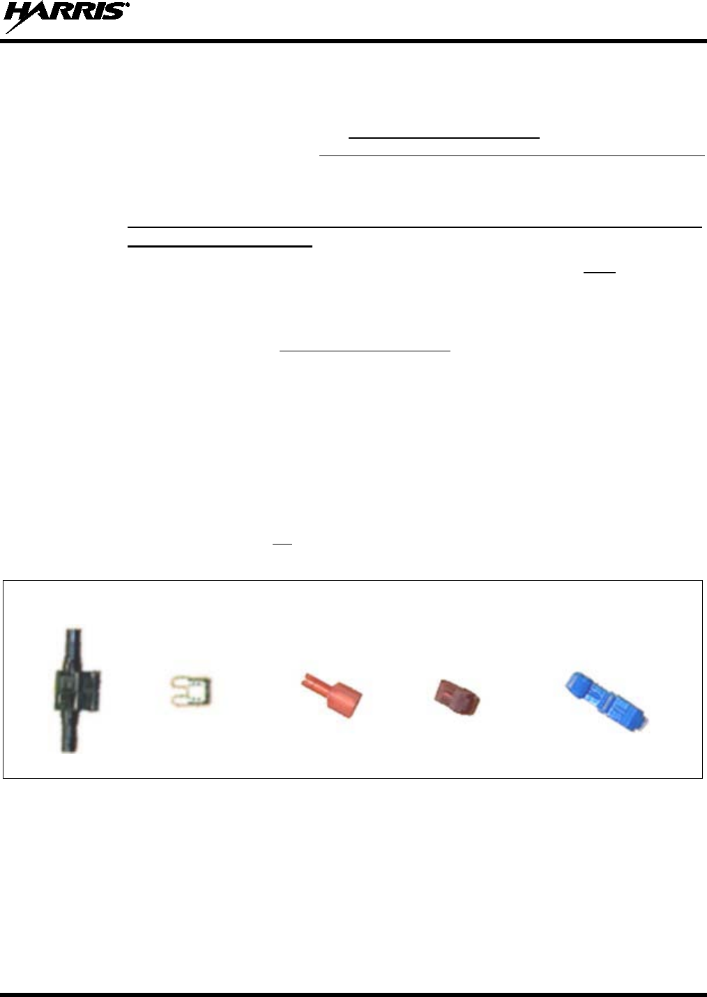
MM-014763-001, Rev. G
79
8.3.4.2.3 Control Head and Radio Are “Hot Wired”
In the “hot-wired” configuration, the control head and radio are turned on and off only by the control
head’s on/off/volume control located on the front panel of the control head. In this configuration, the
control head’s white wire must be connected to unswitched and fused 12-volt vehicle power. Follow the
procedure presented in Section 8.3.4.2.1, except connect the white wire to unswitched battery power
instead of switched (“Accessory”) power. Be sure to fuse this connection with the provided in-line fuse
holder and 3-amp AGC fuse.
8.3.5 Using Vehicle Fuse and T-Tap Kit (Optional) Instead of Waterproof Inline
Fuse Holder (Standard)
The waterproof inline fuse holder and AGC fuse included with the DC Power Cable must be used if the
white wire connection point is located in a harsh environment such as in the vehicle’s engine
compartment. In this case, disregard all information presented in this section, and follow one of the three
procedures presented in Section 8.3.4.2 to connect the white wire.
However, if the connection point is not in a harsh environment, such as under the vehicle’s dash panel,
Vehicle Fuse and T-Tap Kit FS24473 may be ordered and used to make the white wire connection. As
shown in Figure 8-12, this kit includes an ATM fuse holder and fuse, T-tap crimp terminals for tapping
into an existing vehicle switched power wire, and a quick-disconnect terminal. The following installation
procedure is recommended for this optional kit:
1. Locate the switched ignition or “Accessory” power wire (typically at or near the vehicle’s fuse block
or in a vehicle wiring harness) that will be used for the switched ignition power source. It may be
necessary to consult the vehicle manufacturer’s wiring diagram.
2. Route the white wire of the control head’s DC Power Cable from the back of the head to an area near
the switched ignition power source. At the back of the head, be sure to maintain a cable service length
of at least six (6) inches and do not loop the cable.
3. Cut a short section (6 to 8 inches) off the end of the white wire and strip each end of this short wire.
ATM 2-Amp Quick- T-Tap T-Tap
Fuse Holder ATM Disconnect Terminal for Terminal for
Fuse Terminal #22-18 AWG #16-14 AWG
(Gray) (Male Tab) Wire (Red) Wire (Blue)
(Shown Closed)
(Shown Open)
Figure 8-12: Contents of Vehicle Fuse and T-Tap Kit FS24473
4. From the Vehicle Fuse and T-Tap Kit, locate the male-tab quick-disconnect terminal and crimp it to
one end of the short wire.
5. From the same kit, locate the ATM fuse holder and crimp it to the other end of the short wire. The
holder has built-in crimpable joints.
6. Cut the excess length from the white wire of the control head’s power cable, strip it, and crimp it to
the other side of the ATM fuse holder.
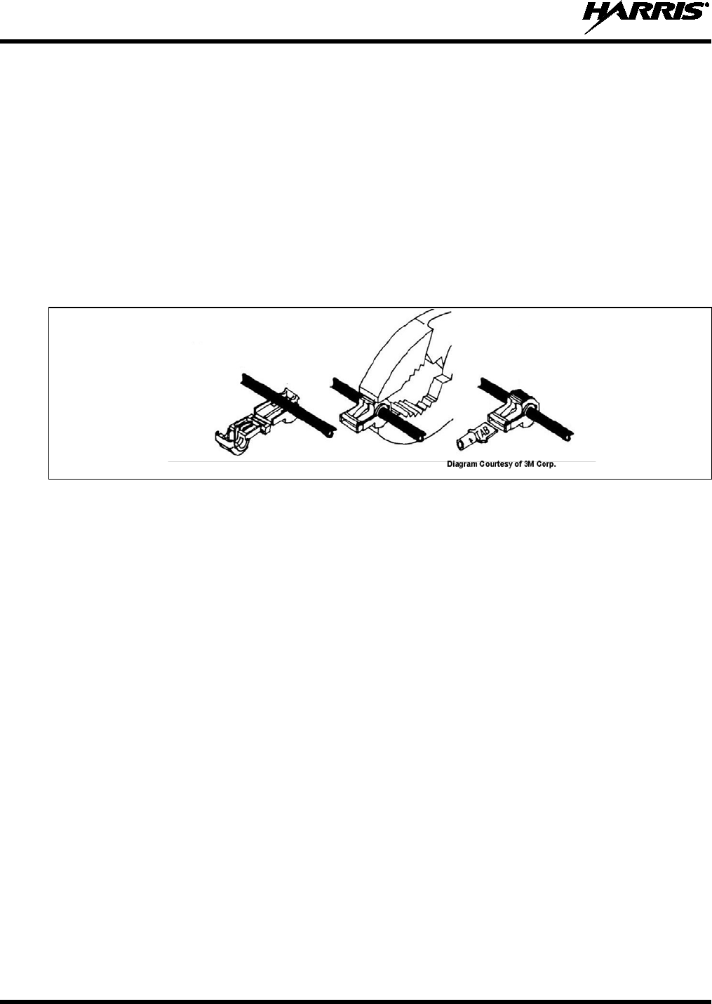
MM-014763-001, Rev. G
80
7. Pull enough of the switched ignition source wire out of the vehicle’s wiring harness so one of the
T-tap terminals may be attached to it.
8. Two T-tap terminals are included in the kit. Based on the gauge of wire, select the proper terminal
size: Red is for use with a 22 to 18-AWG wire, and blue is for use with an 18 to 14-AWG wire.
9. Attach the selected T-tap terminal by fitting the wire into its wire groove and snapping the two halves
together with a pair of pliers as shown in Figure 8-13.
10. Push the male-tab quick-disconnect terminal into the T-tap terminal’s inlet until it is fully engaged.
11. Install the 2-amp ATM fuse into the fuse holder. It is recommended that a piece of electrical tape be
wrapped around the fuse connection to keep the fuse from being jostled out of the holder.
12. Tie and stow these wires as necessary so they remain out of the way of casual contact and wire chafe
is avoided.
Figure 8-13: Attaching T-Tap Terminals to a Switched Power Wire
8.4 HHC-731 HAND-HELD CONTROLLER INSTALLATION
In a remote-mount M7300 mobile radio installation, the HHC-731 hand-held controller can be used in
place of the CH-721 control head. This easy-to-use hand-held mobile radio controller is primarily
designed for use in harsh environments such as maritime (i.e., boating) applications and All-Terrain
Vehicle (ATV) applications. The HHC-731 hand-held controller has easy-to-use buttons, a tough liquid-
crystal display (LCD), and a built-in microphone. As of the publication of this manual, only one (1)
HHC-731 hand-held controller can be connected to a radio, and without any connected CH-721 control
heads. The front of the HHC-731 hand-held controller is shown in Figure 8-14.
Installation procedures for the HHC-731 hand-held controller are included in this section. Procedures
include:
• Mounting the HHC-731 Interface Cable and Bracket (see page 81);
• Connecting CAN Link (see page 82);
• Connecting DC Power (see page 83);
• Mounting the HHC-731 Hanger (see page 86); and,
• Connecting the HHC-731 to the HHC-731 Interface Cable (see page 86).
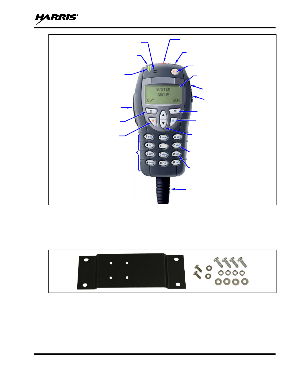
MM-014763-001, Rev. G
81
Figure 8-14: HHC-731 Hand-Held Controller Front View
8.4.1 Mounting the HHC-731 Interface Cable and Bracket
HHC-731 Interface Cable Mounting Bracket Kit KT-018752-001 is show in Figure 8-15. This kit
includes Bracket FM-018681-001 and mounting hardware, which secure the HHC-731 Interface Cable to
a mounting surface. In Table 4-6 and page 31, the bracket kit is item 3, and the cable is item 3.
Figure 8-15: HHC-731 Interface Cable Mounting Bracket Kit KT-018752-001
Follow this procedure to attach the cable to the bracket, and to mount the bracket to a firm surface:
1. Attach the bracket to the large end of the cable using the two #6-32 machine screws and flatwashers
included in the bracket kit. As illustrated in Figure 8-16, the two can be attached either perpendicular
or parallel to each other. The “wings” of the bracket should be positioned away from the cable. Only
two of four center-most holes in the bracket are used.
2. Tighten the two (2) screws securely with a #1 Phillips screwdriver. Do not over-tighten.
3-Line Liquid Crystal
Display (LCD)
Built-In Microphone
Push-To-Talk (PTT)
Button
Up/Down Arrow Buttons
(Selects groups/channels, with default
keypad mapping.)
Transmit
and Busy
Indicators
Menu Button
Volume Down Button
Emergency/Home Button
Cable’s Strain Relief
(cable not shown)
On/Off Power Button
Clear Button
Option Button
Scan Button
Ramp Down Button
(Decreases backlight intensity if controller
is not connected to the radio.)
Volume Up Button
Keypad
Ramp Up Button
(Increases backlight intensity if controller
is not connected to the radio.)
Use the 6 (ADD) key for a + function,
with default keypad mapping.
Use the 9 (DEL) key for a – function,
with default keypad mapping.
Keypad
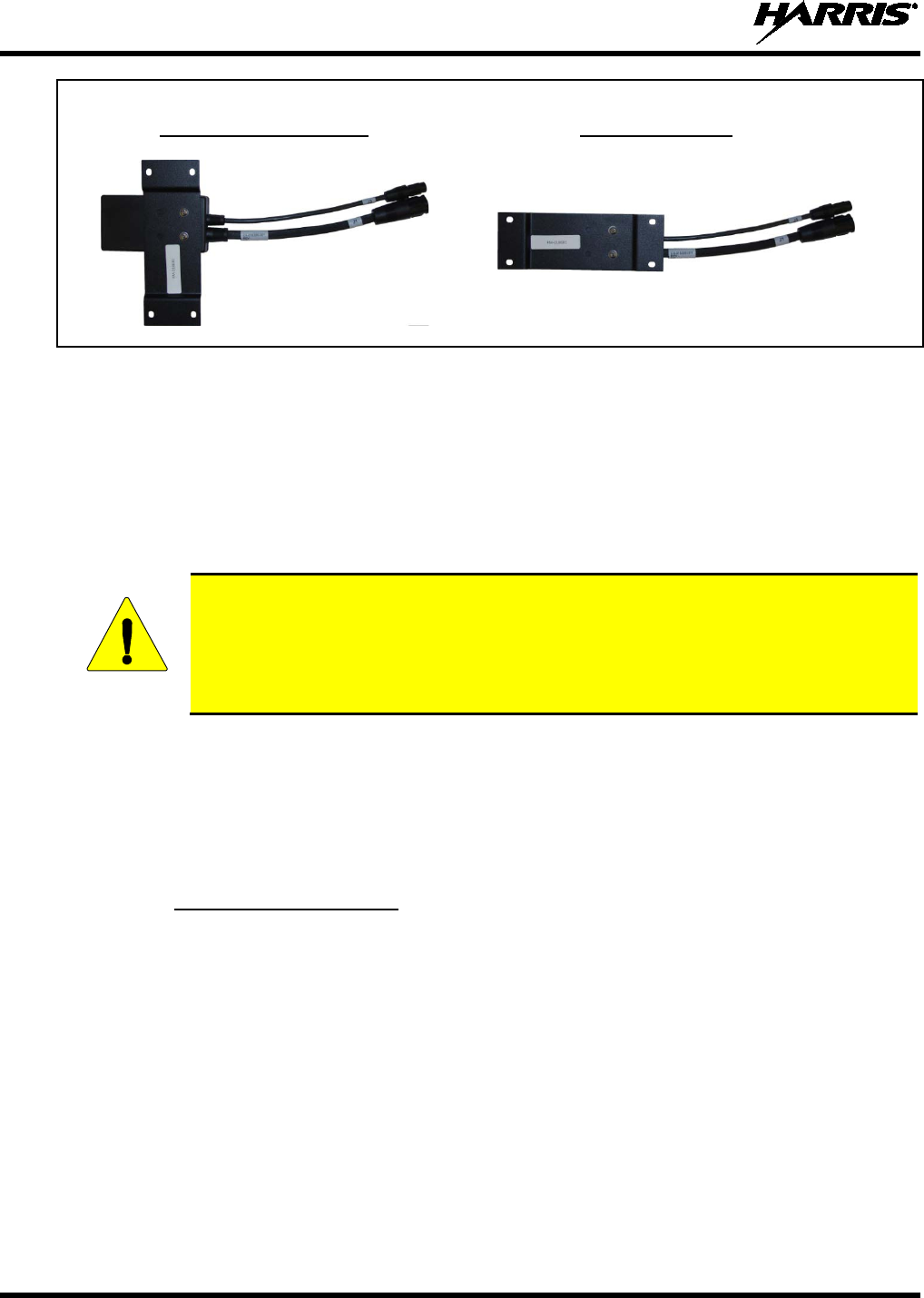
MM-014763-001, Rev. G
82
Bracket Attached Bracket Attached
Perpendicular to Cable: Parallel to Cable:
Figure 8-16: HHC-731 Interface Cable Mounting Bracket-to-Cable Positioning
3. Select a firm mounting surface near the controller, for the bracket. Review and follow the safety and
operator-convenience related information presented in Section 5.1 on page 37. Also, always consider
and include clearance for the mating of the two connectors on each side of the square end of the
cable, and for clearance for the two “pigtail” style cables extending from the bottom of the square
end.
4. Using the four (4) corner holes of the mounting bracket as a template, mark and drill mounting holes
into the selected mounting surface as required.
Before drilling holes and/or installing mounting screws, verify these operations will not
damage or interfere with any existing vehicle component (the fuel tank, a fuel line, the
transmiss
ion housing, existing vehicle wiring, etc.). Always check to see how far the
mounting screws will extend below the mounting surface prior to installation. Always
deburr drilled holes before installing screws.
5. Mount the mounting bracket and cable to the selected mounting surface using the thread-forming
screws, lockwashers, and flatwashers included with the HHC-731 installation kit, or other screws as
required per the mounting surface. Tighten the four screws securely, but do not over-tighten them.
6. Verify the mounting bracket is firmly mounted. Firm mounting prevents unreasonable vibration,
which could damage the cable and/or cause its cable connections to loosen over time.
8.4.2 Connecting CAN Link
Connect the CAN link between the radio’s CAN port and the CAN port connector of the HHC-731
Interface Cable in accordance with this procedure. Connections are illustrated in Figure 8-17:
1. Mate a CAN terminator to either one of the two small 3-pin CAN port connectors on the rear panel of
the radio. The CAN terminator is item 7 in Table 4-6.
2. Obtain a CAN cable and mate it to the other CAN port connector on the rear panel of the radio.
Typically, the 30-foot CAN cable is used, item 8 in Table 4-6. Other length CAN cables may be
used, as listed in Table 4-8 on page 36.
3. Route the CAN cable through the vehicle’s interior wire/cable channeling to the radio. Remove
interior panels, door kick panels, etc., as necessary. Do not route the cable where it will be damaged
by heat sources or by casual contact. Protect the cable from possible chafing and other damage as
necessary.
4. Mate the other end of the cable to the small 3-pin CAN port connector of the HHC-731 Interface
Cable.
CAUTION
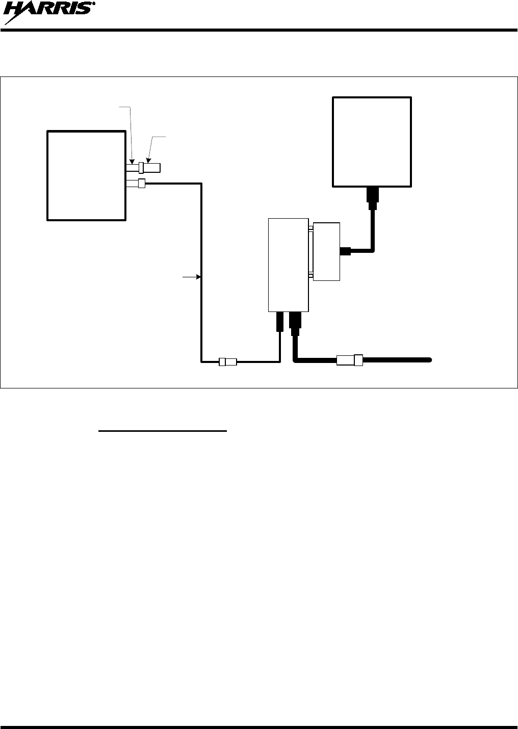
MM-014763-001, Rev. G
83
5. Loop, tie and stow the excess cable as necessary, leaving a service loop at the back of the radio and at
the location of the interface cable.
CAN Terminator
CD-014027-001
(for radio end)
CAN
3-Pin CAN Port
Connectors on
Rear of Radio
(2 places)
CAN
M7300
Mobile
Radio
HHC-731
Hand-Held
Controller
CAN Cable CA-009562-nnn
(where nnn specifies cable
length in feet)
CAN Link
NOTE: No CAN
Terminator is required
at the HHC-731. It is
internally terminated.
J3
DC Power
J1
DC Power
CA-012616-001 (See text for
connection
information)
HHC-731
Interface
Cable
CA-
018399-
001
DB-25(F)
Connector
For Available CAN Cable Lengths and Respective Part Numbers, see Table 4-8 on page 36.
Figure 8-17: M7300-to-HHC-731 CAN Link Connections
8.4.3 Connecting DC Power
Plan the route of the DC Power Cable for HHC-731 hand-held controller carefully. Do not route it where
it will be damaged by heat sources or by casual contact, and protect it from wire chafe per standard
installation methods. The following procedures are recommended:
8.4.3.1 Install DC Power Cable and Make Power and Ground Connections
1. Connect the DC Power Cable (item 6 in Table 4-6) to the large 3-pin connector of the HHC-731
Interface Cable. Visually align the key and gently push and turn the outer locking ring clockwise until
it stops. A click will be sensed to confirm proper mating.
2. Near the HHC-731 Interface Cable’s mounting location, locate a nearby section of vehicle chassis
ground and strip this area of any paint or dirt to expose a bare metal surface.
3. Cut the black wire of the DC Power Cable to the required length, plus a service loop of at least six (6)
inches, then strip it and crimp a ⅜-inch ring terminal to it. Two ring terminals of this type are
included with the cable.
4. Drill a new hole as necessary and attach this ring terminal to chassis ground. Use stainless-steel self-
locking hardware (i.e., machine screws with washers and locking nuts) or other appropriate hardware
to ensure a reliable terminal-to-metal contact. Tighten securely.
MM-014763-001, Rev. G
84
Do not ground the black wire by attaching it via the same hardware that secures
the cable’s mounting bracket.
Before drilling holes and/or installing mounting screws, verify these operations will not
damage or interfere with any existing vehicle component (the fuel tank, a fuel line, the
transmiss
ion housing, existing vehicle wiring, etc.). Always check to see how far the
mounting screws will extend below the mounting surface prior to installation. Always
deburr drilled holes before installing screws.
5. Tie and stow the cable near the HHC-731 Interface Cable’s bracket.
6. For the positive 12-volt DC main power source connection, route the cable’s red wire to the location
of an unswitched 12-volt DC power source, typically near the vehicle’s battery. Remove interior
panels, door kick panels, etc. Protect the wire from possible chafing as necessary. This is the hand-
held controller’s main DC power source.
7. Obtain one of the waterproof (HFB-type) fuse holders included with the DC Power Cable.
8. Cut excess length from the red wire and splice the fuse holder into it, near the location of the
unswitched 12-volt DC power source connection point.
9. Using an appropriate electrical terminal, connect the red wire to the unswitched DC power source. A
⅜-inch ring terminal is included with the cable for this purpose, but another terminal type (not
supplied) should be used as required.
10. Obtain the 5-amp AGC-type fuse included with the cable, and install it into the fuse holder.
Do not share the HHC-731 hand-held controller’s fuse with any other device. Doing so
can cause excess current to flow through the fuse, causing it to blow unnecessarily.
The fuse for the HHC-731 hand-held controller’s red wire is rated at 5 amperes. The
3-amp fuse included with the cable must not be used for fusing the controller’s main
DC power. The 3-amp is used to fuse the controller’s white wire.
8.4.3.2 Connect DC Power Cable’s White Wire
Connect the DC Power Cable’s white wire by following one of the following three procedures, per the
customer’s required on/off power control method:
8.4.3.2.1 Hand-Held Controller and Radio Turn on with Vehicle’s Ignition Switch/Key
With this wiring configuration, the HHC-731 hand-held controller and the radio turn on and off with the
vehicle’s ignition switch/key (power on also requires pressing of the HHC-731’s front panel power on/off
button). The white wire of the HHC-731’s DC Power Cable is sometimes referred to as the “white
ignition switch wire” or the “ignition sense input wire.” In this configuration, the white wire of the
HHC-731’s DC Power Cable connects to a switched power source, typically identified as “Accessory”
power, that switches on and off with the vehicle’s ignition switch/key.
CAUTION
CAUTION
NOTE
CAUTION

MM-014763-001, Rev. G
85
The white ignition sense wire must be connected to a fused power source that switches
from approximately zero volts to approximately +13.6 volts when the vehicle’s ignition
switch/key is turned from the OFF position to the ACCESSORY and RUN positions.
Use of a switched power source that is subject to voltage changes as a result of other
actions, such as opening a vehicle door, may result in undesirable radio power cycles.
1. Locate the vehicle’s switched ignition or “Accessory” power connection point that will be used for
the switched ignition 12-volt DC power source. This point is typically located at or near the vehicle’s
fuse panel. It may be necessary to consult the vehicle manufacturer’s wiring diagram.
2. Route the white wire of the HHC-731’s DC Power Cable to the area near this connection point.
Protect the wire from possible chafing as necessary.
3. Obtain one of the waterproof (HFB-type) fuse holders included with the HHC-731’s DC Power
Cable.
4. Cut excess length from the white wire and splice the fuse holder into it, near the location of the
connection point.
5. Using an appropriate electrical terminal, connect the white wire to the switched power connection
point. An open-barrel spade terminal is included with the cable for this purpose, but another type of
terminal (not supplied) may be used as required.
6. Obtain the 3-amp AGC-type fuse included with the cable, and install it into the fuse holder.
7. Tie and stow all wiring as necessary so it remains out of the way of casual contact and wire chafe is
avoided.
8.4.3.2.2 Hand-Held Controller and Radio Turn On with a Manual Switch
With this wiring configuration, the HHC-731 hand-held controller and radio are turned on and off via an
on/off switch mounted separately from the HHC-731 and radio, not through the vehicle’s ignition
switch/key (power on also requires pressing of the HHC-731’s front panel power on/off button). This
configuration is used when, for example, the radio must remain on even when the ignition key must be
removed from the vehicle and a separate on/off switch is acceptable and/or required. In this configuration,
the white wire of the HHC-731’s DC Power Cable connects to a fused switched power source such as that
provided by a toggle switch mounted on the vehicle’s dash panel.
1. Route the white wire of the HHC-731’s DC Power Cable to an area near the location of the panel-
mounted on/off switch. Protect the wire from possible chafing as necessary.
2. Cut a short section (6 to 8 inches) off the end of the white wire and strip the ends.
3. Obtain one of the waterproof (HFB-type) fuse holders included with the HHC-731’s DC Power
Cable, and crimp one half of it to one end of the short section of wire.
4. Using an appropriate electrical terminal, connect this short white wire to unswitched 12-volt DC
power source at or near the vehicle’s fuse box.
5. Cut another section of white wire from the cable. This wire must be long enough to reach from this
fuse holder to the location of the panel-mounted on/off switch.
6. Strip one end of this wire and crimp the other half of the waterproof fuse holder to this wire end.
7. Strip the other end of this wire and, using an appropriate electrical terminal, connect it to the common
terminal of the switch.
8. Connect the white wire of the power cable to the load (switched) side of the switch.
NOTE

MM-014763-001, Rev. G
86
9. If not already, mount the switch to the vehicle’s dash panel, or other customer-selected location.
10. Obtain the 3-amp AGC-type fuse included with the cable, and install it into the fuse holder.
11. Tie and stow these wires as necessary so they remain out of the way of casual contact and wire chafe
is avoided.
12. Label this power switch accordingly. For example: “RADIO ON/OFF.”
8.4.3.2.3 Hand-Held Controller and Radio Are “Hot Wired”
In the “hot-wired” configuration, the HHC-731 hand-held controller and radio are turned on and off only
by the on/off button on the front of the HHC-731. In this configuration, the HHC-731’s white wire must
be connected to unswitched and fused 12-volt vehicle power. Follow the procedure presented in Section
8.4.3.2.1, except connect the white wire to unswitched battery power instead of switched (“Accessory”)
power. Be sure to fuse this connection with the provided in-line fuse holder and 3-amp AGC fuse.
8.4.4 Mounting the HHC-731 Hanger
An HHC-731 hanger is provided with the HHC-731 hand-held controller. Follow this procedure to
mount the hanger:
1. Select a mounting surface location that will position the HHC-731 within easy reach of the radio
operator’s location. Consult with the customer as necessary. Also review the information presented in
Section 5. The selected location must have sufficient clearance for the HHC-731 when it is hung in
the hanger.
2. Using the hanger as a template, drill mounting holes in the surface of the selected location. Use self-
locking hardware (i.e., machine screws with washers and locking nuts), self-drilling screws, or other
appropriate hardware as necessary. Tighten securely.
3. Stow the HHC-731 in the hanger and verify it can be easily inserted and removed. A spring detent
action keeps the HHC-731 firmly stowed.
8.4.5 Connecting the HHC-731 to the HHC-731 Interface Cable
1. Mate the HHC-731’s female DB-25 connector to the male DB-25 connector of the HHC-731
Interface Cable. Tighten the two jackscrews securely, but do not over-tighten them.
2. If not already, tie and stow the HHC-731 Interface Cable.
3. Hang the HHC-731 in its hanger.
8.4.6 Connecting a Siren/Light Control System
Follow this procedure to connect a siren/light control system to the HHC-731 hand-held controller:
1. Obtain Accessory Cable 19B802554P24. This cable’s diagram is included in Section 11.4.
2. Mate the Accessory Cable’s male DB-25 connector (P1) to the female DB-25 connector of the
HHC-731 Interface Cable. Tighten the two jackscrews securely, but do not over-tighten them.
3. Mate the male DB-25 connector of the siren/light control system’s cable to the female DB-25
connector of Accessory Cable.
4. Continue with the installation instructions included with the siren/light control system.

MM-014763-001, Rev. G
87
9 SPEAKER INSTALLATION
9.1 FRONT-MOUNT RADIO INSTALLATION
In a front-mount radio installation, total speaker cable length (of both cables) is approximately 10 feet
(308 centimeters). Therefore, to include service loops in these cables, the speaker must be mounted within
approximately 9.5 feet (290 centimeters) of the M7300 mobile radio.
1. Select a location for the speaker that will allow for proper listening range with a moderate volume
setting.
2. Install the speaker using the hardware and mounting bracket supplied with it. For the speaker’s part
number, see Table 4-4 (page 28).
3. Route the speaker cable to the rear of the M7300 mobile radio.
4. Connect the M5300/M7300 Option Cable CA-012349-001 (item 5 in Table 4-4) to the DB-44
connector on the rear of the radio. Tighten the cable’s two (2) jackscrews securely. See Section 11.1
for additional information on this cable.
5. Mate the Option Cable’s 2-pin connector (identified P2) to the 2-pin connector on the end of the
speaker cable. A mild click will be sensed to confirm proper mating.
6. Route the cables out of the way of casual contact. Tie and stow as necessary.
9.2 REMOTE-MOUNT RADIO INSTALLATION
9.2.1 With CH-721 Control Head
In a remote-mount mobile radio installation with the CH-721 control head, an audio amplifier in the
CH-721 control head drives the external speaker.
For this case, total speaker cable length of both cables between the control head and speaker is
approximately five (5) feet. Therefore, to include service loops in these cables, the speaker must be
mounted within approximately 4.5 feet of the installation’s CH-721 control head.
1. Select a location for the speaker that will allow for proper listening range with a moderate volume
setting.
2. Install the speaker using the hardware and mounting bracket supplied with it. For the speaker’s part
number, see Table 4-5 (page 29).
3. Route the speaker cable to the rear of the CH-721 control head.
4. Mate the 6-inch speaker cable (item 8 in Table 4-5) to the 2-pin connector at the rear of the control
head by visually aligning the ¾-moon-shaped keys of the connectors, and then pushing and turning
the outer locking ring of the cable connector clockwise until it stops. A mild click will be sensed to
confirm proper mating.
5. Connect the speaker cable’s 2-pin plastic connector to the respective mating connector on the 6-inch
speaker cable.
6. Route the cables out of the way of casual contact. Tie and stow as necessary.

MM-014763-001, Rev. G
88
9.2.2 With HHC-731 Hand-Held Controller
In a remote-mount mobile radio installation with the HHC-731 hand-held controller, an audio amplifier in
the mobile radio drives the external speaker. The HHC-731 does not have a high-power speaker audio
amplifier. The following speaker installation procedure is recommended for this case:
1. Obtain the speaker, item 9 in Table 4-6.
2. Select a location for the speaker that will allow for proper listening range with a moderate volume
setting.
3. Install the speaker using the hardware and mounting bracket supplied with it.
4. If no other optional connections are required at the back of the radio, obtain Speaker Only Option
Cable CA-012349-007. This cable is item 10 in Table 4-6. It is approximately 20-feet long.
However, if other optional connections are required at the back of the radio (such as GPS NMEA-
formatted serial data connections), obtain M5300/M7300 Option Cable CA-012349-001. This cable
is approximately 5.5-feet long. In this case, the length of the cable’s 2-wire speaker leads may not be
sufficient to reach the 2-pin speaker connector of the option cable, and they will need to be
lengthened using approved splicing techniques.
5. Connect the option cable to the DB-44 connector on the rear of the radio. Tighten the two jackscrews
securely, but do not over-tighten them.
6. Route the option cable’s 2-wire speaker lead to the 2-pin connector of the speaker cable.
7. Mate the option cable’s 2-pin connector to the 2-pin connector of the speaker cable.
8. After mating the two 2-pin connectors, secure them together with nylon tie wrap so they will not
disconnect with vehicle vibrations or other movements.
9. Route the cables out of the way of casual contact. Tie and stow as necessary.
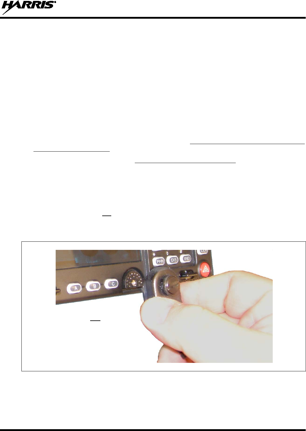
MM-014763-001, Rev. G
89
10 MICROPHONE ATTACHMENT
There are several versions of microphones available for use with the radio. Each has a 17-pin flush-mount
type connector that mates with the mic connector on the front panel of the control head. The mic’s
connector includes a captive thumbscrew that secures it to the mic connector on the front panel of the
control head. A microphone clip is included with each microphone. The radio can be configured to
provide a monitor function when the microphone is cradled in the clip. Connect the mic to the control
head and install the clip as follows:
1. As illustrated in Figure 10-1, grasp the mic’s connector with a thumb and index finger on the sides of
the connector just adjacent to the thumbscrew.
2. Position connector just in front of the control head’s mic connector so its male pins can engage
straight into the female (socket) pins of the control head’s mic connector. The thumbscrew must be
oriented directly above the hanging mic cable.
3. Mate the two connectors by pressing them fully together. Do not apply any force to the thumbscrew
when mating the connectors.
4. Tighten the thumbscrew finger-tight. Do not use a screwdriver to tighten it.
5. Using the microphone clip as a template, drill mounting holes in the surface of the selected location.
6. Select a mounting surface location that has clearance for the mic when it is clipped to the clip, and
then attach the microphone clip to the surface. Use self-locking hardware (i.e., machine screws with
washers and locking nuts), self-drilling screws, or other appropriate hardware as necessary. Tighten
securely. Microphones used with the CH-721 control head have integrated hookswitches. Therefore,
the microphone clip does not need to be grounded.
7. Clip the microphone to the clip.
Figure 10-1: Attaching the Microphone to the CH-721Control Head
As illustrated, do not apply any
force to the thumbscrew when
mating the mic connectors.
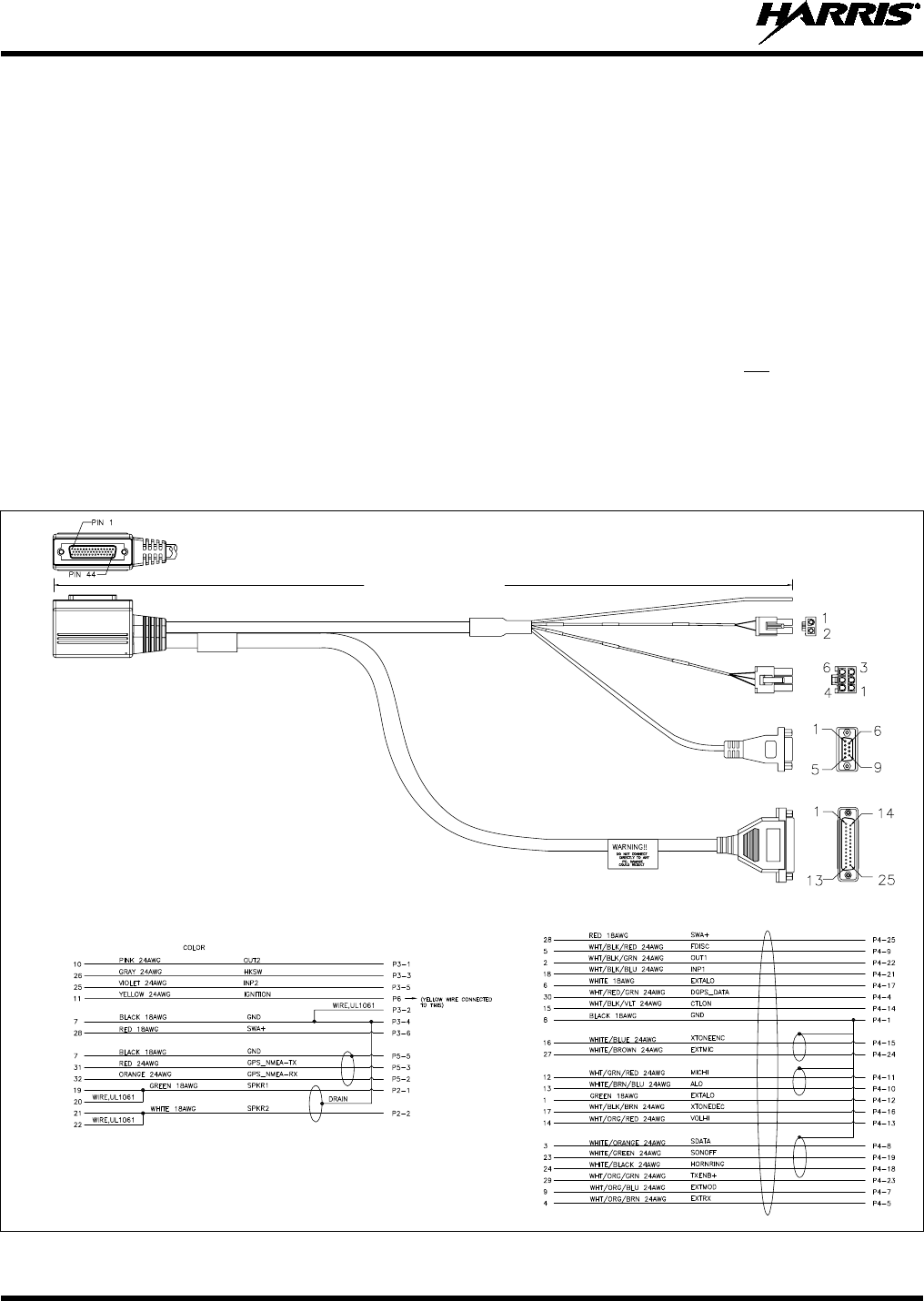
MM-014763-001, Rev. G
90
11 OPTIONAL CABLES
11.1 M5300/M7300 OPTION CABLE CA-012349-001
M5300/M7300 Option Cable CA-012349-001 connects to the 44-pin I/O connector on the rear of the
radio. It breaks out into several smaller standardized connectors, allowing straightforward access to
external I/O interfaces provided by the radio. The cable also shortens radio removal and re-installation
time when required. The cable is shown in Figure 11-1 below. The cable’s 44-pin D-subminiature
connector that mates with the connector on the rear of the radio is identified P1.
P2, the cable’s 2-pin connector, provides connections for an external speaker in a front-mount M7300
mobile radio installation, or in a remote-mount radio installation with an HHC-731 hand-held controller.
For connection information, see Section 9.1 and Section 9.2.2 respectively. P2 is not used in a remote-
mount radio installation with a CH-721 control head, since the audio amplifier in the head drives the
external speaker (speaker connection is made at the rear of the control head).
P3, the cable’s 6-pin connector, is a connector for basic accessories (e.g., hookswitch, etc.).
P4, the cable’s D-subminiature 25-pin connector, provides audio and data connections for optional
equipment such as an external siren and light system (e.g., Federal Signal SS2000 SmartSiren®).
(Made From PS-CA-012349 Rev. C)
Figure 11-1: M5300/M7300 Option Cable CA-012349-001
ASSEMBLY DIAGRAM
WIRING DIAGRAM
Approximately 66 inches
(170 centimeters)
P6
P2
P3
P5
P4
P1
(Pin-Out
View)
P1
(Side
View)
P1
P1
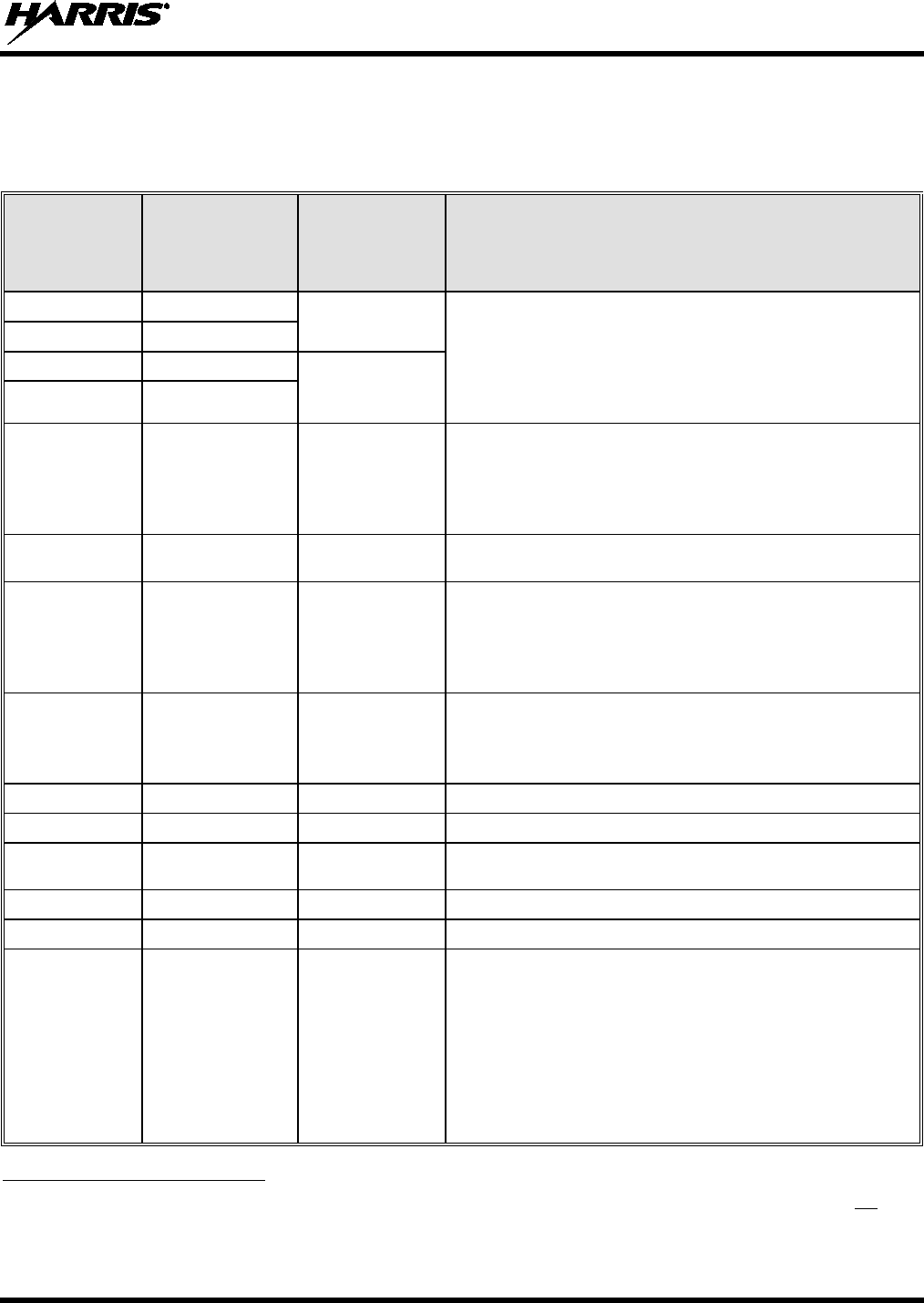
MM-014763-001, Rev. G
91
P5, the cable’s D-subminiature 9-pin connector, provides NMEA-formatted GPS serial data connections
for the external computer processing the NMEA-formatted GPS data received by the radio’s internal GPS
receiver. See Section 12 on page 100 for additional information.
Table 11-1: M5300/M7300 Option Cable CA-012349-001 Interconnections
44-PIN I/O
CABLE
CONNECTOR
P1 PIN
SIGNAL NAME TO/FROM DESCRIPTION
19 SPKR1 P2 pin 1 Speaker Audio Outputs 1 and 2. These two outputs are not
used in a remote-mount radio installation with a CH-
721
control head. However, in a front-
mount radio installation,
and in a remote-mount radio installation with an HHC-
731
hand-held controlle
r, these two outputs drive the radio
installation’s external speaker.
20 SPKR1
21 SPKR2 P2 pin 2
22 SPKR2
10 OUT2 P3 pin 1
Digital Output 2 (open-collector, 500 mA / 30 V maxi-
mum). Use P3 pin 2 or 4 for ground.
For ECP, configure via the “External Output Control Line
2” in Radio Personality Manager’s (RPM’s) External I/O
dialog box.
7 GND P3 pins 2 & 4 Chassis Ground (fused on radio’s
PK Board at
3.15 amps).
26 HKSW P3 pin 3
Digital Input for Hookswitch (default) or for radio
PTT.
Active = Ground. Inactive = Open.
For use as a PTT input with OpenSky
“rear panel software”
R15A and later, send the following AT command
to the
radio: AT@PTT_INPUT2. Also see P4 pin 21.
25 INP2 P3 pin 5
Digital Input 2. Active = Ground. Inactive =
Open. Use P3
pin 2 or 4 for ground.
For ECP, configure via the “Auxiliary Input 2” in Radio
Personality Manager’s (RPM’s) External I/O dialog Box.
28 SWA+ P3 pin 6 Switched A+ (DC Power) Output.
8 GND P4 pin 1 Chassis ground (fused on PK Board at 3-amps).
30 DGPS_DATA P4 pin 4 GPS Receiver Module DGPS Correction Data Serial Data
Input (NMEA-Formatted).
4 EXTRX P4 pin 5 External Rx Audio Input (from external/2
nd
receiver; summed).
9 EXTMOD P4 pin 7 External Tx Audio Input (not normally used).
3 SDATA P4 pin 8
In a front-
mount M5300/M7300 radio installation, this pin
for the siren/PA interface is the siren serial data output
(open-collector/open-
drain) from the radio’s mounted
(local) CH-721. It serially
transfers siren and light control
data from the CH-721 to a connected third-
party siren
and light system (e.g., Federal Signal SS2000
SmartSiren). Data rate = 1200
bps. Connects to
SS2000’s DB-9 pin 3. For a remote-mount radio installa-
tion, see footnote 5.
5 In a remote-mount M5300/M7300 mobile radio installation, this pin on the radio’s DB-44 connector is typically not used.
For the CH-721 control head, use the respective pin on the CH-721 Option Cable’s female DB-25 pin connector; see
Section 11.3 for additional information. For the HHC-731 hand-held controller, use the respective pin on the HHC-731
Interface Cable’s female DB-25 connector; see Section 11.6 for additional information.

MM-014763-001, Rev. G
92
Table 11-1: M5300/M7300 Option Cable CA-012349-001 Interconnections
44-PIN I/O
CABLE
CONNECTOR
P1 PIN
SIGNAL NAME TO/FROM DESCRIPTION
5 FDISC P4 pin 9 Buffered Discriminator Audio Output (not normally used).
13 ALO P4 pin 10 In a front-
mount M5300/M7300 radio installation, this
600-ohm AC-
coupled differential audio output from the
mounted (local) CH-721 is typically not used. In a remote-
mount M5300/M7300 radio installation, these two pins of
the radio’s DB-44 connector are not functional.
12 MICHI P4 pin 11
1
EXTALO
P4 pin 12
In a front-mount M5300/M7300 radio installation,
VOLHI
(a single-ended AC-coupled audio signal)
and EXTALO
(signal ground)
provide public address (PA) mic audio
from the mounted (local) CH-721 to a
siren and light
system, such as the
Federal Signal SS2000 SmartSiren.
Pin 13 connects to SS2000’s DB-
9 pin 5. Pin 12
connects to SS2000’s DB-9 pin 6. For a remote-
mount
radio installation,
these two pins can provide an unmuted
volume-level-controlled single-
ended audio signal to
external devices.
14 VOLHI P4 pin 13
15 CTLON P4 pin 14 Control-On Digital Input for data-
only radio on/off power
control. See Section 8.2.3 for additional information.
16 XTONEENC P4 pin 15
External Tone Encode Audio Input (default) or
Auxiliary
Mic Audio Input.
For use as an aux mic audio input with OpenSky
“rear
panel software” R15A and later
, send the following AT
command to the radio: AT@MIC_REAR_INPUT2.
Also
see P4 pin 24.
17 XTONEDEC P4 pin 16 External Tone Decode Audio Output.
6 EXTALO P4 pin 17 Reference/Ground for external audio.
24 HORNRING P4 pin 18
In a front-
mount M5300/M7300 radio installation, this pin
for the siren/PA interface is the horn/ring logic input to the
radio’s mounted (local) CH-721. When a connected third-
p
arty siren and light system (e.g., Federal Signal
SmartSiren SS2000) has its horn/ring function active, this
input is used to signal the head/radio as such. Connects
to SS2000’s DB-9 pin 8. For a remote-
mount radio
installation, see footnote 5.
23 SONOFF P4 pin 19
In a front-
mount M5300/M7300 radio installation, this pin
for the siren/PA interface is the siren on/off logic output
(open-collector) from the radio’s mounted (local) CH-
721.
It is the signal that powers the connected third-
party siren
and light system (e.g., Federal Signal SmartSiren
SS2000) on and off. Connects to SS2000’s DB-
9 pin 4.
For a remote-mount radio installation, see footnote 5.

MM-014763-001, Rev. G
93
Table 11-1: M5300/M7300 Option Cable CA-012349-001 Interconnections
44-PIN I/O
CABLE
CONNECTOR
P1 PIN
SIGNAL NAME TO/FROM DESCRIPTION
18 INP1 P4 pin 21
Digital Input 1. Active = Ground. Inactive = Open.
Use
P4 pin 1 for ground.
For use as a PTT input with OpenSky “rear pane
l
software”
R15A and later, send the following AT
command to the radio: AT@PTT_INPUT1. Also see P3
pin 3.
For ECP, configure via the “Auxiliary Input 1” in Radio
Personality Manager’s (RPM’s) External I/O dialog Box.
2 OUT1 P4 pin 22
Digital Output 1 (open-collector, 500 mA / 30 V maxi-
mum). Use P4 pin 1 for ground.
For ECP, configure via the “External Output Control Line
1” in Radio Personality Manager’s (RPM’s) External I/O
dialog Box.
29 TXENB+ P4 pin 23 Transmit Enable B+ Output (open-collector).
Active/Radio
Transmitting = Ground. Inactive/Not Transmitting = Open.
(not normally used).
27 EXTMIC P4 pin 24
External/Auxiliary Mic Audio Input.
Use P4 pin 17 for
ground.
For use as an aux mic audio input with OpenSky
“rear
panel software” R15 and later
, send the following AT
command to the radio: AT@MIC_REAR_INPUT1. Also
see P4 pin 15.
28 SWA+ P4 pin 25 Switched A+ DC Power Output (not normally used).
32 GPS_NMEA_RX P5 pin 2 NMEA-Formatted GPS Receiver Position Data
Serial
Data Output.
31 GPS_NMEA_TX P5 pin 3 NMEA-Formatted GPS
Receiver Module Initialization
Data Serial Data Input.
7 GND P5 pin 5 Ground for GPS Serial Data Signals (fused on radio’s
PK
Board at 3.15 amps).
11 IGNITION Yellow Wire Unused/Spare ignition sense input.
33 — 44 — (no connections)
These twelve pins of P1 (i.e., the 44-
pin connector on the
rear of the radio) are not used/not connected
when
M5300/M7300 Option Cable CA-012349-001 is con-
nected to P1.
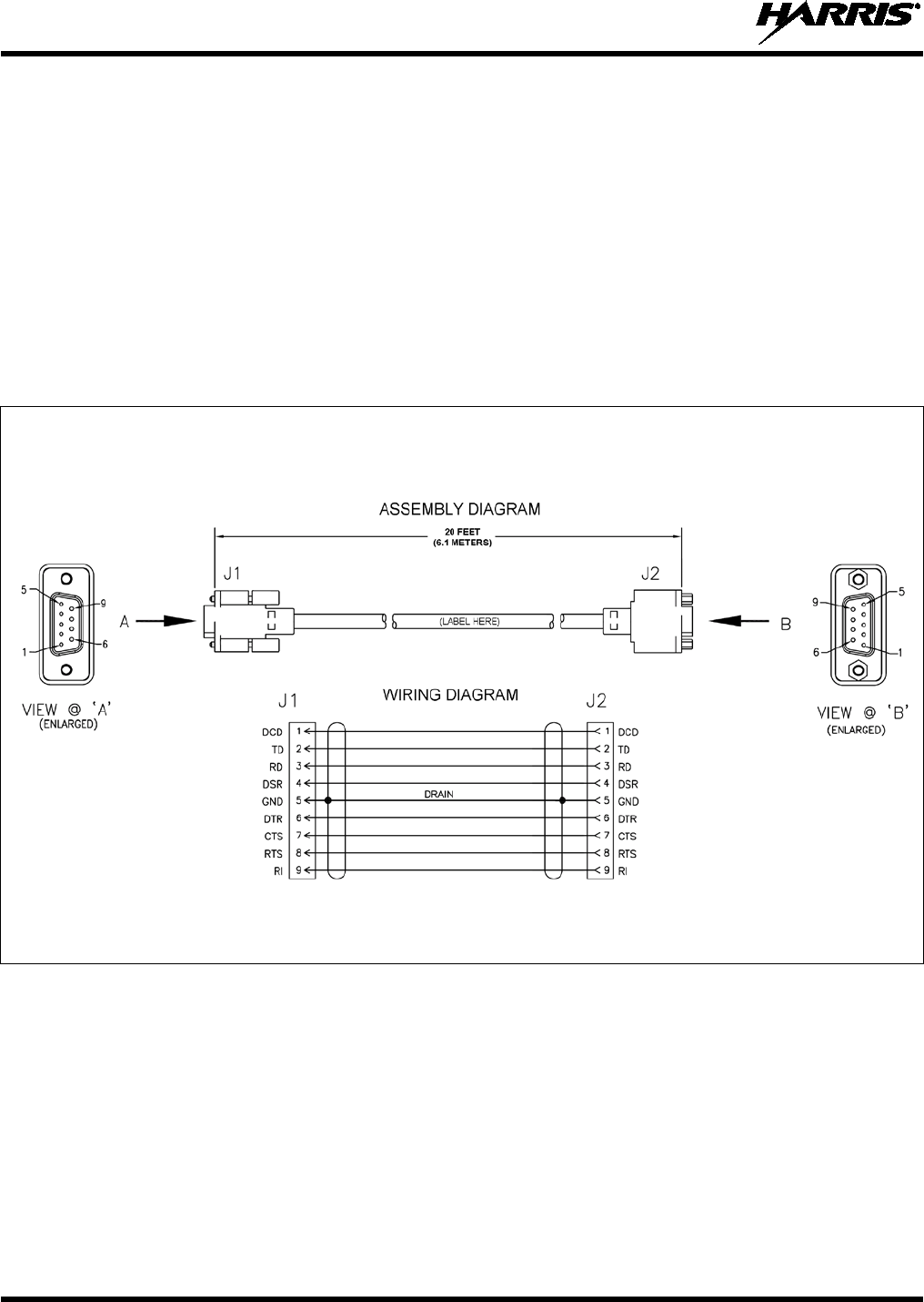
MM-014763-001, Rev. G
94
11.2 SERIAL PROGRAMMING CABLE CA-013671-020
Serial Programming Cable CA-013671-020 (20 feet long) can be used to program and configure the
M7300 mobile radio via a Personal Computer. Also, the cable can be used to extend GPS
NMEA-formatted serial data connections available at connector P5 of the radio’s Options Cable. The
cable’s assembly and wiring diagrams are shown in Figure 11-2 below.
The cable’s male DB-9 connector (J1) mates to the female DB-9 serial port connector on the rear of the
radio. Alternately, if the cable is being used to carry GPS NMEA-formatted serial data from the radio, this
male DB-9 connector mates to connector P5 of M5300/M7300 Option Cable CA-012349-001.
The cable’s female DB-9 connector (J2) mates to a PC’s male DB-9 serial port connector. If the utilized
PC is not equipped with a DB-9 serial port connector, the use of a suitable adapter is required, such as
USB-to-RS-232 Adapter Cable CN24741-0001. As of the publication of this manual, CN24741-0001 is
available via the Customer Resource Center; refer to Section 3.3 on page 24 for contact information.
(Made From PS-CA-013671 Rev. -)
Figure 11-2: Serial Programming Cable CA-013671-020
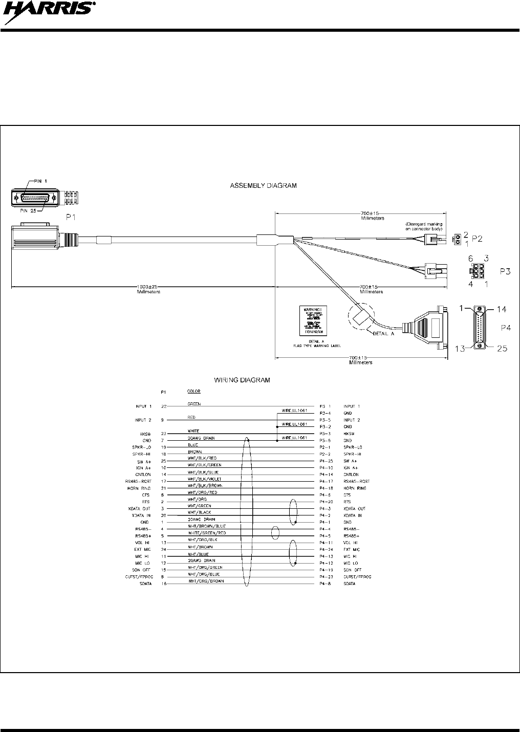
MM-014763-001, Rev. G
95
11.3 CH-721 OPTION CABLE CA-011854-001
CH-721 Option Cable CA-011854-001 can be used to connect optional equipment to the 25-pin
D-subminiature (DB-25) connector on the rear of the CH-721. This cable expands the connections
available at the 25-pin connector to three (3) separate connectors. The cable’s assembly and wiring
diagrams are shown in Figure 11-3 below.
(Made From PS-CA-011854 Rev. D)
Figure 11-3: CH-721 Option Cable CA-011854-001
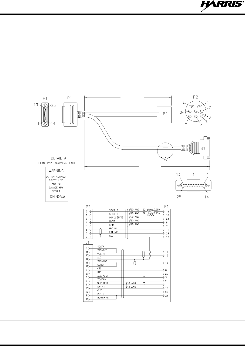
MM-014763-001, Rev. G
96
11.4 ACCESSORY CABLE 19B802554P24
When a remote-mount radio installation employs the HHC-731 hand-held controller, Accessory Cable
19B802554P24 is required to make connections to an external siren and light control system. This cable’s
male DB-25 connector, identified P1, mates to the female DB-25 connector of HHC-731 Interface Cable.
The cable’s assembly diagram is illustrated in Figure 11-4 below.
Connector J1 mates with a cable provided with the siren and light control system. The respective
connection procedure is presented in Section 8.4.6 of this manual.
Connector P2 is not used in this application of the cable.
(Made From 19B802554 Rev. AD, Sh. 24)
Figure 11-4: Accessory Cable 19B802554P24
0.6 meters
(23.6 inches)
1.75 meters
(68.9 inches)
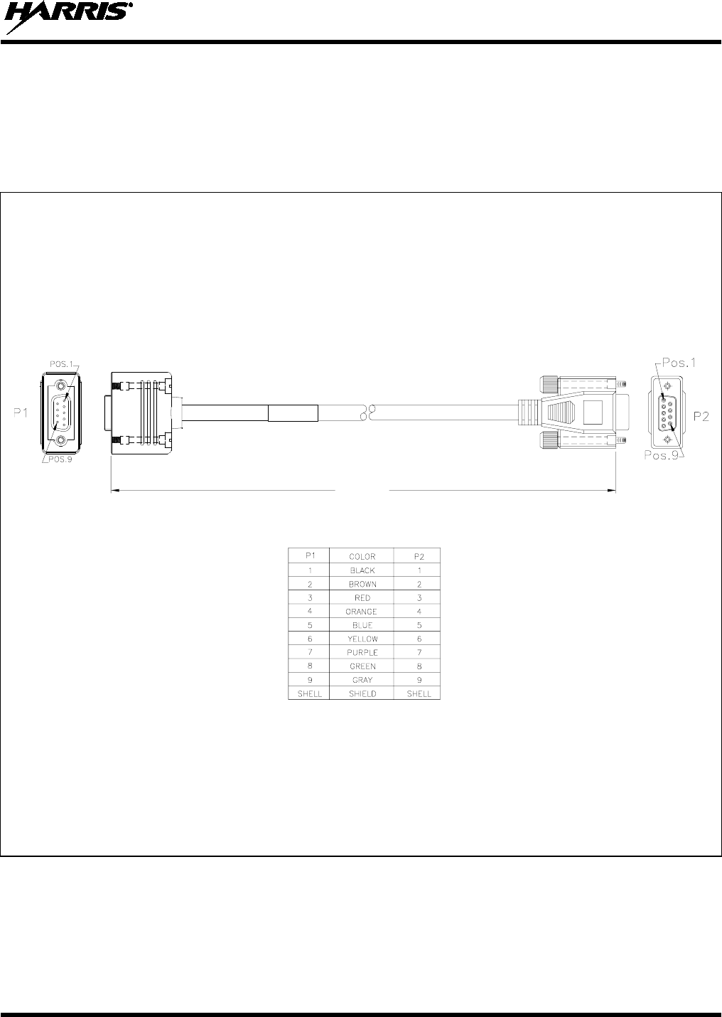
MM-014763-001, Rev. G
97
11.5 CH-721 SERIAL PROGRAMMING CABLE CA-104861
Serial Programming Cable CA-104861 (5 feet) can be used to program and configure the CH-721 control
head via a Personal Computer. This cable has a female DB-9 connector on one end for connection to the
PC’s serial port connector and a male DB-9 connector on the other end for connection to the serial port
connector on the rear of the head. The cable’s assembly diagram and wiring list are shown in Figure 11-5
below.
(Made From PS-CA-104861 Rev. A)
Figure 11-5: Programming Cable CA-104861
WIRING LIST
5 FEET
(1.524 METERS)
ASSEMBLY DIAGRAM
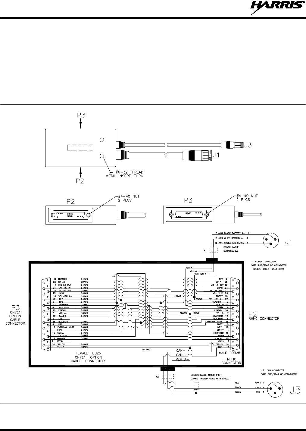
MM-014763-001, Rev. G
98
11.6 HHC-731 INTERFACE CABLE CA-018399-001
HHC-731 Interface Cable CA-018399-001 interconnects a DC power cable and the CAN cable from the
radio to the HHC-731 hand-held controller. It also has a 25-pin connector that can be used to connect
optional equipment to the HHC-731. The cable’s assembly and wiring diagrams are shown in Figure 11-6
below. Connector J1 mates with the DC power cable from the main and switched fused power sources.
Connector J3 mates with the CAN cable from the radio. Connector P2 (male DB-25) mates to the coiled
cord of the CH-721 hand-held controller. Connector P3 (female DB-25) is the connector for optional
connections, such an external siren and light system (e.g., Federal Signal SS2000 SmartSiren®). Refer to
Section 8.4 in this manual for installation instructions.
(Made From PS-CA-018399 Rev. A, Sh. 1 and 3)
Figure 11-6: HHC-731 Interface Cable CA-018399-001
FEMALE
PARTIAL SIDE VIEW PARTIAL SIDE VIEW
REAR VIEW
WIRING DIAGRAM
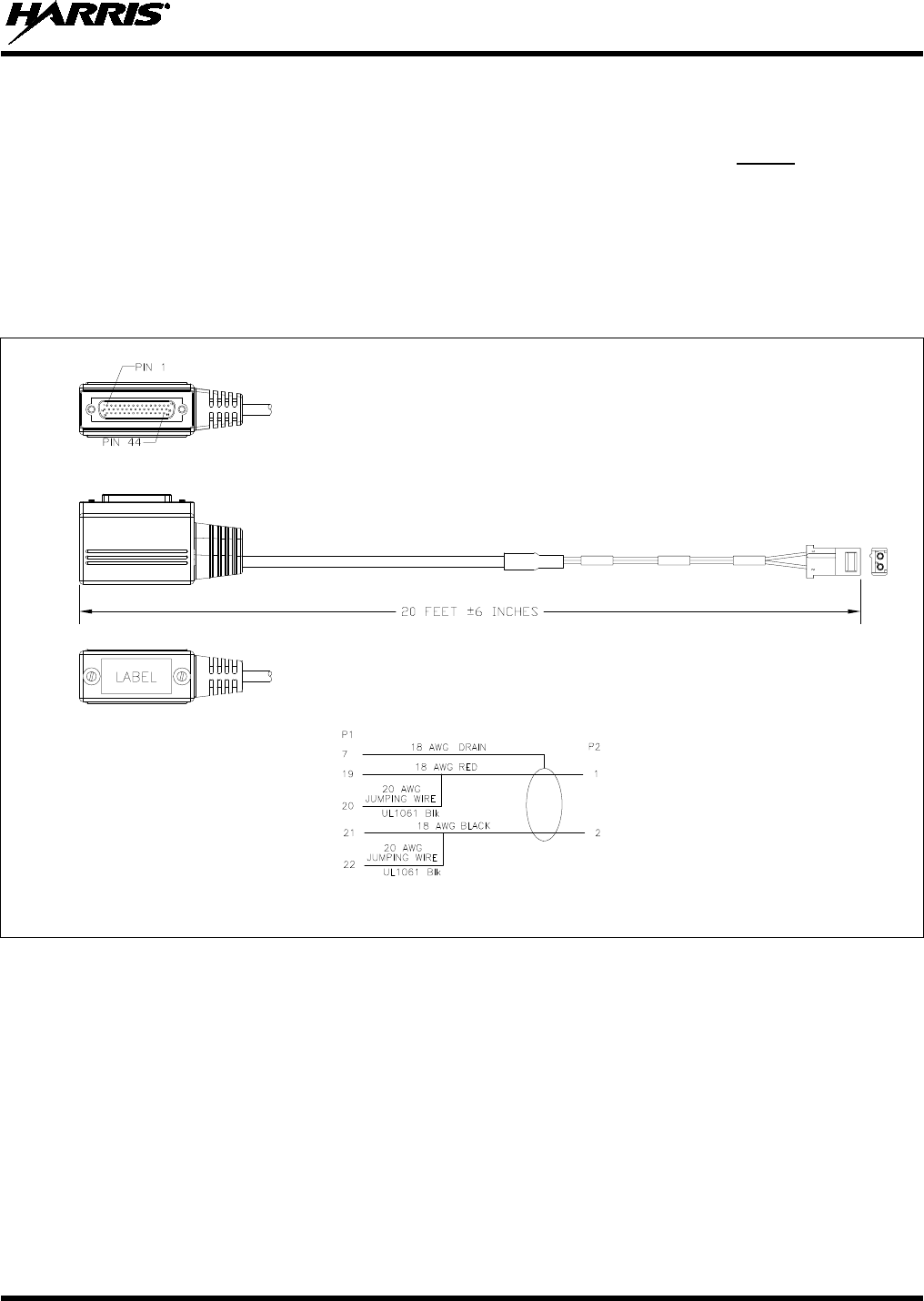
MM-014763-001, Rev. G
99
11.7 SPEAKER-ONLY OPTION CABLE CA-012349-007
Speaker-Only Option Cable CA-012349-007 is typically only used to make speaker connections to the
radio when the HHC-731 hand-held controller is employed. Optional connections cannot be made to the
44-pin (DB-44) connector on the rear of the radio when the cable is employed. This 20-foot cable
connects the radio’s high-power speaker audio output to the 2-wire leads of the speaker. Refer to Section
9.2.2 on page 88 for the respective installation instructions. This cable can also be used for the same
purpose in front-mount M7300 mobile radio installation, if no optional connections must be made to the
radio’s 44-pin (DB-44) connector. The cable’s assembly and wiring diagrams are shown in Figure 11-7
below. Connector P1 mates to the 44-pin connector on the rear of the radio. Connector P2 mates to the
speaker’s 2-pin connector.
(Made From PS-CA-012349, Rev. F, Sh. 10)
Figure 11-7: Speaker-Only Option Cable CA-012349-007
P1
ASSEMBLY DIAGRAM
WIRING DIAGRAM
P2
1
2
(Pin-Out
View)
P1
(Bottom
View)
P1
(Jackscrew
End
View)
MM-014763-001, Rev. G
100
12 GPS NMEA-FORMATTED SERIAL DATA
CONNECTION
To obtain GPS NMEA-formatted serial data from the radio, M5300/M7300 Option Cable CA-012349-
001 is required. In addition, the radio must be equipped with the GPS receiver option. Follow this
procedure to complete the GPS NMEA-formatted serial data connections:
1. Obtain M5300/M7300 Option Cable CA-012349-001. Each “leg” of this cable is approximately
65 inches long (166 centimeters).
2. Connect the cable’s 44-pin D-subminiature (DB-44) male connector to the DB-44 female connector
on the rear panel of the radio. Tighten the two jackscrews with a small flathead screwdriver. Do not
over-tighten.
3. Connect the cable’s DB-9 female connector to the computer’s serial port DB-9 male connector—
either directly or extended via serial cable CA-013671-020 (a 20-foot-lon cable); see Section 11.2.
Tighten the screws firmly, and then route the cabling as required. If the computer is not equipped with
a DB-9 serial port connector, the use of a suitable adapter is required, such as USB-to-RS-232
Adapter Cable CN24741-0001.
4. Follow the manufacturer’s instructions on processing the NMEA-formatted GPS data from the radio.
If the M5300/M7300 Option Cable is not available, a 3-wire serial cable can be field-
fabricated. On the radio end, this cable must interface to the three GPS-related signals of
the radio’s 44-pin I/O Cable connector (pins 7, 31 and 32). See Table 11-1 for additional
information.
Industry software to process GPS information through this interface is not supported by
Harris.
NOTE
NOTE
MM-014763-001, Rev. G
101
13 INITIAL POWER-UP TEST
1. At the radio’s main waterproof (HFB-type) fuse holder installed near the vehicle battery, insert the
15-amp AGC-type fuse that was included with the radio’s DC Power Cable.
2. Tie and stow all fuse holders at this location to prevent excess vibration/movement.
3. Carefully reconnect the vehicle’s battery ground cable.
4. If not already, temporarily connect the mobile antenna cable from the vehicle-mounted mobile
antenna to the female TNC RF connector on the rear panel of the radio. This is a temporary
connection until test procedures in Section 14 are complete.
5. If the radio is equipped with the GPS receiver option, permanently connect the antenna cable from the
GPS antenna (or mobile/GPS combo antenna) to the female SMA connector on the rear panel of the
radio. The male SMA connector on most GPS antenna cables has a 5/16-inch hex collar, so the use of
a wrench of this same size is normally required for tightening. However, some may have collars with
only knurled surfaces, so a standard wrench or torque wrench cannot be used. In either case, do not
over tighten the connector and do not twist the cable when tightening.
6. If the installation is wired so the vehicle’s ignition key/switch turns the radio on and off, turn the
switch to the Accessory or Run position.
7. If the control head is not already powered up, do so by rotating its on/off/volume control clockwise
out of the detent position. For the HHC-731, press the on/off power button located just above the
display.
8. Verify the control head/hand-held controller has powered-up by observing its display. If the display is
not functioning, refer to Section 8.2.1 as necessary.
Unlike many mobile radio products, the radio powers-up to the state of last control.
As long as the software configuration parameters have been loaded, successful installation is almost
immediately realized:
• After a short boot-up sequence, the control head/hand-held controller displays login information
and/or a talk group.
• If no errors are displayed, the installation is most-likely properly wired.
• If an error is displayed, recheck all cable connections, verify all fuses are properly installed, and
verify battery power on the load side of the fuses, etc. If problems persist, contact the Technical
Assistance Center (see page 25).
• Consult the Operator’s Manual for operational information.
Refer to Section 14 for performance test information.
NOTE
MM-014763-001, Rev. G
102
14 PERFORMANCE TESTS
This section includes procedures to verify the performance of the installation’s mobile antenna system.
There are three (3) procedures in this section:
• Changing Operating Mode for Tests
• Testing by Transmitting into a Dummy Load (a 50-Ohm RF Terminator)
• Testing by Transmitting into the Mobile Antenna
The accuracy of test results depends upon a DC power source in the range of 13.6 volts
DC ±10%, with a current capacity of greater than 15 amps. Make sure the vehicle’s
battery is fully charged by running the engine for a few minutes before the test, and
keep the engine running during the test procedures. Abide by
the following
WARNING!
If the vehicle’s engine must remain running, the vehicle location should be well
ventilated so exhaust fumes from the engine do not cause harm!
If a vehicle equipped with this radio requires jump-starting, the radio installation’s
main AGC fuse (15-amp) should be removed from the holder prior to jump-starting.
Doing so will prevent damage to the radio system.
Prior to installation, the radio’s power level should be configured appropriately. The
wide range of power levels indicated in the following procedures takes into account
such things as: customer’s requirements; measurement errors, especially to include
uncalibrated equipment; cabling losses; and voltage and temperature variations. By no
means should the result from Performance Testing in this section be construed as the
exact value of power level output from the radio, as the
value is set and more
accurately measured in the factory. The va
lues obtained in these test procedures
determine a successful installation only.
14.1 CHANGING OPERATING MODE FOR TESTS
To complete tests in this section, placing the radio in a conventional mode and using an average-
responding wattmeter to measure RF transmit power is recommended. However, if the radio is not
programmed for conventional mode operations (i.e., OpenSky Trunking Protocol (OTP) mode is available
but EDACS/Conventional/P25 (ECP) modes are not), tests will require a peak-reading RF wattmeter to
measure RF transmit power. To select either conventional or OpenSky mode, use one of the following
procedures:
14.1.1 Changing from OpenSky to Conventional
This procedure assumes the control head/hand-held controller is configured with default keypad mapping.
1. Apply power to the radio and turn it on via the On/Off/Volume Control on the CH-721 control
head. See Figure 8-5.
For the CH-731 hand-held controller, use the On/Off Power Button located just above its display.
See Figure 8-14.
CAUTION
WARNING
CAUTION
NOTE

MM-014763-001, Rev. G
103
2. For the control head, use the •/•• Ramp Control to scroll through the menu until Mode Menu
appears in the display.
For the hand-held controller, use the Ramp Up Button or Ramp Down Button located on the top
of the controller to scroll through the menu until Mode Menu appears in the display.
3. For the control head, select an available conventional channel/system via the +/- Ramp Control.
For the hand-held controller, use the 6 (ADD) or 9 (DEL) keys on the keypad to select an available
conventional channel/system.
4. For the control head, confirm the selection by pressing the MENU button, then toggling the
Ramp Control once (to select Y for Yes), followed by pressing the MENU button again. The radio
will enter the selected mode as indicated by the display.
For the hand-held controller, confirm the selection by pressing the Menu Button (M), then the
Ramp Up Button or Ramp Down Button, and then the Menu Button (M) again.
5. For the control head, select a conventional channel for test transmissions using the System/Group/-
Channel Selection Control.
For the hand-held controller, select a conventional channel for test transmissions using the (up
arrow) button or the (down arrow) button located just below the display.
14.1.2 Changing from Conventional to OpenSky
This procedure assumes the control head/hand-held controller is configured with default keypad mapping.
1. Apply power to the radio and turn it on via the On/Off/Volume Control on the CH-721 control
head; see Figure 8-5. For the CH-731 hand-held controller, use the On/Off Power Button just
above its display; see Figure 8-14.
2. For the control head, use the •/•• Ramp Control to scroll through the menu until the required
OpenSky system’s name is displayed.
For the hand-held controller, use the Ramp Up Button or Ramp Down Button located on the top
of the controller to scroll through the menu until the required OpenSky system’s name is displayed.
3. After a few seconds, the radio will automatically transition to OTP mode for operations on the
selected OpenSky system.
4. If the radio is not programmed for auto-login, login to the OpenSky system. For login instructions,
refer to the respective operator’s manual or quick guide as necessary. The quick guide is included
with the radio when it ships from the factory.
5. For the control head, select a talk group for test transmissions using either the •/•• Ramp Control
or the System/Group/Channel Selection Control (required control per programming).
For a hand-held controller, select a talk group for test transmissions using the (up arrow) button or
the (down arrow) button located just below the display.
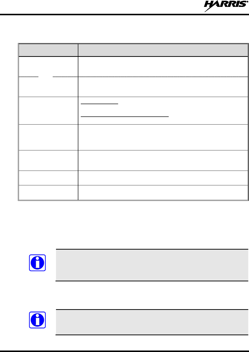
MM-014763-001, Rev. G
104
14.2 REQUIRED TEST EQUIPMENT
Table 14-1: Required Test Equipment
TEST EQUIPMENT MODEL / PART NUMBER & DESCRIPTION
Average-Responding
Wattmeter
(for conv. measurements)
Bird Electronic Corp. Model 43 (or equivalent) with Type
N female
connectors at input and output ports.
Peak-Reading
Wattmeter
(for OpenSky measurements)
Bird Electronic Corp. Model 4314B (or equivalent) with Type
N female
connectors at input and output ports.
Wattmeter
Slug
For a VHF Radio: Bird Electronic Corp. Element 50C or 100C (50 or 100-Watt
max. respectively), 100 - 250 MHz frequency range (or equivalent).
For a UHF or a 700 & 800 MHz Radio: Bird Electronic Corp. Element 50E
(50-Watt max.), 400 - 1000 MHz frequency range (or equivalent).
RF Coaxial
Jumper Cable
Pasternack Enterprises PE3661-36 (or equivalent) 50-Ohm Coaxial Cable
with TNC male connector and Type N male connector, approximately three
(3) feet in length. The utilized cable must have VSWR below 1.5:1 within
the RF passband.
N-to-TNC
RF Adapter
Pasternack Enterprises PE9090 (or equivalent) Type N male to TNC female
adapter. Required to connect the cable of the vehicle-mounted antenna to
the wattmeter.
50-Ohm RF Terminator
(“Dummy Load”) Pasternack Enterprises PE6106 (or equivalent) 50-ohm RF terminator rated
at greater than 50 watts power, with Type N male connector.
Vehicle-Mounted
Antenna Tests are performed with the vehicle-mounted antenna per the installation
described in Section 6 of this manual.
14.3 TRANSMITTING INTO A DUMMY LOAD
1. Using the Type N male to TNC male RF coaxial jumper cable, connect the radio’s antenna connector
to the wattmeter’s input connector. Refer to Figure 14-1 as necessary.
2. Connect the 50-ohm dummy load to the wattmeter’s output connector, in place of the antenna cable
from the vehicle-mounted antenna.
As previously stated, if conventional mode is not available per radio programming
(i.e., OTP mode is available but ECP mode is not), a peak-reading RF wattmeter is
required to measure RF transmit power. Otherwise, the use of an average-responding
wattmeter is recommended. See Table 14-1.
3. If not already, turn the radio on and set it to the required operating mode (based upon available radio
programming and test equipment). Refer to Section 14.1 as necessary.
4. Set the radio to a test talk group or conventional channel, if available.
It is recommended that a test talk group/channel be allocated for this testing. This
same group should be used during the antenna test procedure which is presented in the
subsequent section.
NOTE
NOTE
or
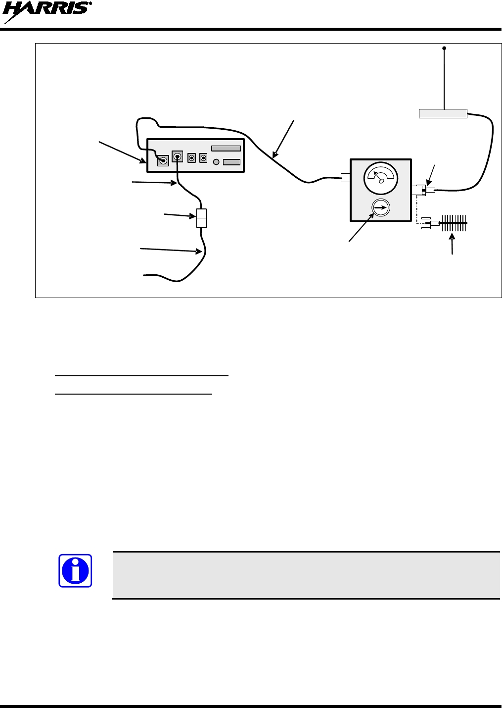
MM-014763-001, Rev. G
105
IN
OUT
M7300
Mobile Radio
(Rear View)
Radio’s DC
Power Cable
3-Pin
Connectors
Installation’s DC
Power Cable
From 13.8-Volt Fused
Power Source
TNC Male-to-Type N Male
Coaxial Jumper Cable
CAN Cable, Option Cable, and
GPS Antenna Cable connections
not are indicated.
Vehicle-Mounted Antenna
Type N Male-to-
TNC Female
RF Adapter
Wattmeter
50-Ohm RF
Terminator
(“Dummy Load”)
Wattmeter Slug
(see text)
Figure 14-1: Wattmeter Connections for Antenna System Tests
5. Position the wattmeter’s slug to measure forward RF output power. Rotate it if necessary. The arrow
on the face of the slug must point away from the radio and towards the dummy load for forward
power measurements.
6. For conventional mode transmissions, set the wattmeter to measure average RF power.
For OpenSky mode transmissions, set the wattmeter to measure peak RF power.
7. Key the radio’s transmitter via the microphone’s PTT button.
8. For a VHF or a high-split UHF (440 to 512 MHz) band transmission, compare the wattmeter’s
reading with the target RF output power range of between 39.8 and 63 watts (50 watts ±1 dB). This
transmit output power range assumes the radio is currently configured for high-power transmit.
For a 700 MHz band transmission, compare the wattmeter’s reading with the target RF output power
range of between 15.1 and 23.9 watts (19 watts ±1 dB). This transmit output power range assumes
the radio is currently configured for high-power transmit.
For an 800 MHz band transmission, compare the wattmeter’s reading with the target RF output power
range of between 27.8 and 44.1 watts (35 watts ±1 dB). This transmit output power range assumes
the radio is currently configured for high-power transmit.
Transmit only for as
long as needed to take the measurement, then immediately
disable the transmission.
9. If the wattmeter reading is within the range, record the measured value in the appropriate space on
the data collection form near the end of this manual.
If the wattmeter reading is outside the range, verify the radio’s power supply voltage (i.e., battery
voltage) is within the specified range, recheck all connections and measure the RF output power
again. If this fails to produce a reading within the range, replace it and repeat this procedure. If
problems persist, contact the Technical Assistance Center (see page 25).
NOTE
MM-014763-001, Rev. G
106
14.4 TRANSMITTING INTO THE MOBILE ANTENNA
1. Connect the antenna cable from the vehicle-mounted antenna to the wattmeter as shown in Figure
14-1.
2. If not already, turn the radio on and set it to the required operating mode (based upon available radio
programming and test equipment). Refer to Section 14.1 as necessary.
3. Set the radio to a test talk group or conventional channel, if available.
It is recommended that a test talk group/channel be allocated for this testing.
Otherwise, interference with other radio users in the system may occur. Also, during
transmissions, always observe the RF exposure-
related safety information
presented in Section 1.2 (begins on page 7).
4. Position the wattmeter’s slug to measure forward RF output power. Rotate it if necessary. The arrow
on the face of the slug must point away from the radio and towards the antenna for forward power
measurements.
5. For conventional mode transmissions, set the wattmeter to measure average RF power.
For OpenSky mode transmissions, set the wattmeter to measure peak RF power.
6. Key the radio’s transmitter via the microphone’s PTT button.
7. For a VHF or a high-split UHF (440 to 512 MHz) band transmission, compare the wattmeter’s
reading with the target RF output power range of between 39.8 and 63 watts (50 watts ±1 dB). This
transmit output power range assumes the radio is currently configured for high-power transmit.
For a 700 MHz band transmission, compare the wattmeter’s reading with the target RF output power
range of between 15.1 and 23.9 watts (19 watts ±1 dB). This transmit output power range assumes
the radio is currently configured for high-power transmit.
For an 800 MHz band transmission, compare the wattmeter’s reading with the target RF output power
range of between 27.8 and 44.1 watts (35 watts ±1 dB). This transmit output power range assumes
the radio is currently configured for high-power transmit.
Transmit only for as long as needed to take the measurement, then immediately
disable the transmission.
8. If the wattmeter reading is within the range, record the value in the appropriate space on the data
collection form near the end of this manual.
If the wattmeter reading is outside the range, verify the radio’s power supply voltage (i.e., battery
voltage) is within the specified range, recheck all connections, and measure the forward power again.
If the installation employs a ¼-wave unity-gain antenna, observe the following NOTE. If these
checks/corrections fail to produce a reading within the range, check all cabling and connections and
repeat the testing procedure to this point. In the event the wattmeter reading still falls outside the
range, replace the antenna, make sure all connections are seated firmly, and repeat the testing
procedure. If problems persist, contact the Technical Assistance Center (see page 25).
NOTE
NOTE
MM-014763-001, Rev. G
107
If the mobile radio installation employs a ¼-wave unity-gain antenna (part number
AN102800V1 or AN102800V2), the driven element (i.e., whip) of the antenna must
be trimmed to the proper length in order to minimize antenna system VSWR. Refer
to the instructions included with the antenna for trimming instructions.
9. Position the wattmeter’s slug to measure reverse (reflected) RF power from the antenna. The arrow
on the face of the slug must point away from the antenna and to the radio to measure reverse power.
10. Key the radio’s transmitter via the microphone’s PTT button.
11. Compare the wattmeter reading with the RF power output range of 2 watts or less.
Transmit only for as long as needed to take the measurement, then immediately disable
the transmission.
12. If the wattmeter reading is within the range, record the value in the appropriate space on the data
collection form near the end of this manual.
If the wattmeter reading is outside the range, make sure the antenna is consistent with the specified
frequency range of the radio. Recheck all antenna connections, and measure the reverse power again.
If the installation employs a ¼-wave unity-gain antenna, observe the NOTE that immediately follows
step 8. If these checks/corrections fail to produce a reading within the range, replace the antenna and
repeat the entire antenna test procedure. Any value exceeding the maximum allowable reflected
power value will result in a diminished RF output signal. If problems persist, contact the Technical
Assistance Center (see page 25).
13. Disconnect the coaxial cable jumper and wattmeter.
14. Permanently connect the cable from the vehicle-mounted antenna to the radio’s antenna cable by
mating the two TNC connectors together. Use two pairs of soft-jaw pliers to gently tighten this
connection. Do not over tighten and do not twist either cable.
15. Make several test calls on the radio system to verify operation of the mobile radio. Before making the
calls, select other talk groups or conventional channels, as required to verify operation.
To prevent RF leakage and ensure peak performance, make sure the RF connectors are
tight, but do not over-tighten so connector damage will not occur.
Improper installation of the RF cables may lead not only to poor radio
performance but also to harmful exposure to RF electromagnetic energy.
Testing is complete. The radio is now ready for normal communications.
NOTE
NOTE
NOTE
WARNING

MM-014763-001, Rev. G
108
(This Page Intentionally Blank)
MM-014763-001, Rev. G
109
14.5 TEST PERFORMANCE DATA FORM
Enter the information requested on this data collection form. Clip this form and file it as a permanent record of
the tested performance of the M7300 mobile radio installation.
Clip
Here
Company Performing Installation
Technician Performing Test
Date of Test
(mm/dd/yyyy)
Mobile Radio Serial Number
Antenna Make and Model Numbers
Power into a Dummy
Load
Watts
Forward Power with
Antenna
Reflected Power
with Antenna
Watts
Watts

MM-014763-001, Rev. G
110
15 COMPLETE THE INSTALLATION
Double-check the following items before considering the installation completed:
• Verify all newly installed mechanical hardware is mounted securely and all respective mounting
hardware is tight.
• Verify all electrical interconnections are connected properly and the associated connector attachment
hardware is tight. Pay special attention to all RF antenna cables!
• Verify all related fuses are correctly installed and properly rated.
• Verify all electrical cables and wiring are tied, stowed, and protected so they are out of the way of
casual contact, away from sources of extreme heat, and wire chafing cannot occur. Pay special
attention to all RF antenna cables!
• To prevent fumes from entering the vehicle’s passenger compartment, seal the hole/grommet/wire
combination at the firewall with a silicon-based sealer.
• Verify all vehicle components are properly reinstalled such as kick panels, headliners, and seats.
• If the installation includes a separately-mounted on/off power switch for manually turning the radio
(and possibly other systems) on and off, verify it is labelled accordingly. For example: “Radio
ON/OFF.”
• Remove all tools and unused hardware from the vehicle.
• Verify the test performance data has been recorded on the data collection form shown in this manual.
16 WARRANTY REGISTRATION
Please register this product within ten (10) days of purchase. Registration validates the warranty coverage,
and enables Harris to contact you in case of any safety notifications issued for this product.
Registration can be made on-line at www.pspc.harris.com/CustomerService or by contacting Harris
Warranty Administration at the following:
United States and Canada:
• Phone Number: 1-800-368-3277, Option 4 (toll free)
• Fax Number: 1-434-455-6821
• E-mail: WarrantyClaims@Harris.com
International:
• Phone Number: 1-434-455-6403
• Fax Number: 1-434-455-6676
• E-mail: WarrantyClaims@Harris.com

MM-014763-001, Rev. G
111
17 WARRANTY
A. Harris Corporation, a Delaware Corporation, through its RF Communications Division (hereinafter
"Seller") warrants to the original purchaser for use (hereinafter "Buyer") that Equipment manufactured
by or for the Seller shall be free from defects in material and workmanship, and shall conform to its
published specifications. With respect to all non-Seller Equipment, Seller gives no warranty, and only
the warranty, if any, given by the manufacturer shall apply. Rechargeable batteries are excluded
from this warranty but are warranted under a separate Rechargeable Battery Warranty (ECR-7048).
B. Seller’s obligations set forth in Paragraph C below shall apply only to failures to meet the above
warranties occurring within the following periods of time from date of sale to the Buyer and are
conditioned on Buyer’s giving written notice to Seller within thirty (30) days of such occurrence:
1. for fuses and non-rechargeable batteries, operable on arrival only.
2. for parts and accessories (except as noted in B.1), ninety (90) days.
3. for P7300, P7200, P7100IP, P5400, P5300, P5200, P5100, P3300, M7300, M7200 (including V-
TAC), M7100IP, M5300 and M3300 radios, two (2) years, effective 10/01/2007.
4. for Unity® XG-100P, three (3) years.
5. for all other equipment of Seller’s manufacture, one (1) year.
C. If any Equipment fails to meet the foregoing warranties, Seller shall correct the failure at its option (i)
by repairing any defective or damaged part or parts thereof, (ii) by making available at Seller’s factory
any necessary repaired or replacement parts, or (iii) by replacing the failed Equipment with equivalent
new or refurbished Equipment. Any repaired or replacement part furnished hereunder shall be
warranted for the remainder of the warranty period of the Equipment in which it is installed. Where
such failure cannot be corrected by Seller’s reasonable efforts, the parties will negotiate an equitable
adjustment in price. Labor to perform warranty service will be provided at no charge during the
warranty period only for the Equipment covered under Paragraph B.3 and B.4. To be eligible for no-
charge labor, service must be performed at Seller’s factory, by an Authorized Service Center (ASC)
or other Servicer approved for these purposes either at its place of business during normal business
hours, for mobile or personal equipment, or at the Buyer’s location, for fixed location equipment.
Service on fixed location equipment more than thirty (30) miles from the Service Center or other
approved Servicer’s place of business will include a charge for transportation.
D. Seller’s obligations under Paragraph C shall not apply to any Equipment, or part thereof, which (i) has
been modified or otherwise altered other than pursuant to Seller’s written instructions or written
approval or, (ii) is normally consumed in operation or, (iii) has a normal life inherently shorter than the
warranty periods specified in Paragraph B, or (iv) is not properly stored, installed, used, maintained or
repaired, or, (v) has been subjected to any other kind of misuse or detrimental exposure, or has been
involved in an accident.
E. The preceding paragraphs set forth the exclusive remedies for claims based upon defects in or
nonconformity of the Equipment, whether the claim is in contract, warranty, tort (including
negligence), strict liability or otherwise, and however instituted. Upon the expiration of the warranty
period, all such liability shall terminate. The foregoing warranties are exclusive and in lieu of all other
warranties, whether oral, written, expressed, implied or statutory. NO IMPLIED OR STATUTORY
WARRANTIES OF MERCHANTABILITY OR FITNESS FOR PARTICULAR PURPOSE SHALL
APPLY. IN NO EVENT SHALL THE SELLER BE LIABLE FOR ANY INCIDENTAL,
CONSEQUENTIAL, SPECIAL, INDIRECT OR EXEMPLARY DAMAGES.
This warranty applies only within the United States.
Harris Corporation Harris Corporation
RF Communications Division RF Communications Division
221 Jefferson Ridge Parkway 1680 University Avenue
Lynchburg, VA 24501 Rochester, NY 14610
1-800-528-7711 1-585-244-5830
ECR-7047L