HARRIS TR-0076-E XG-25M 700/800 MHz 35W User Manual 14221 1510 2000 Rev A XG 25M Mobile Radio
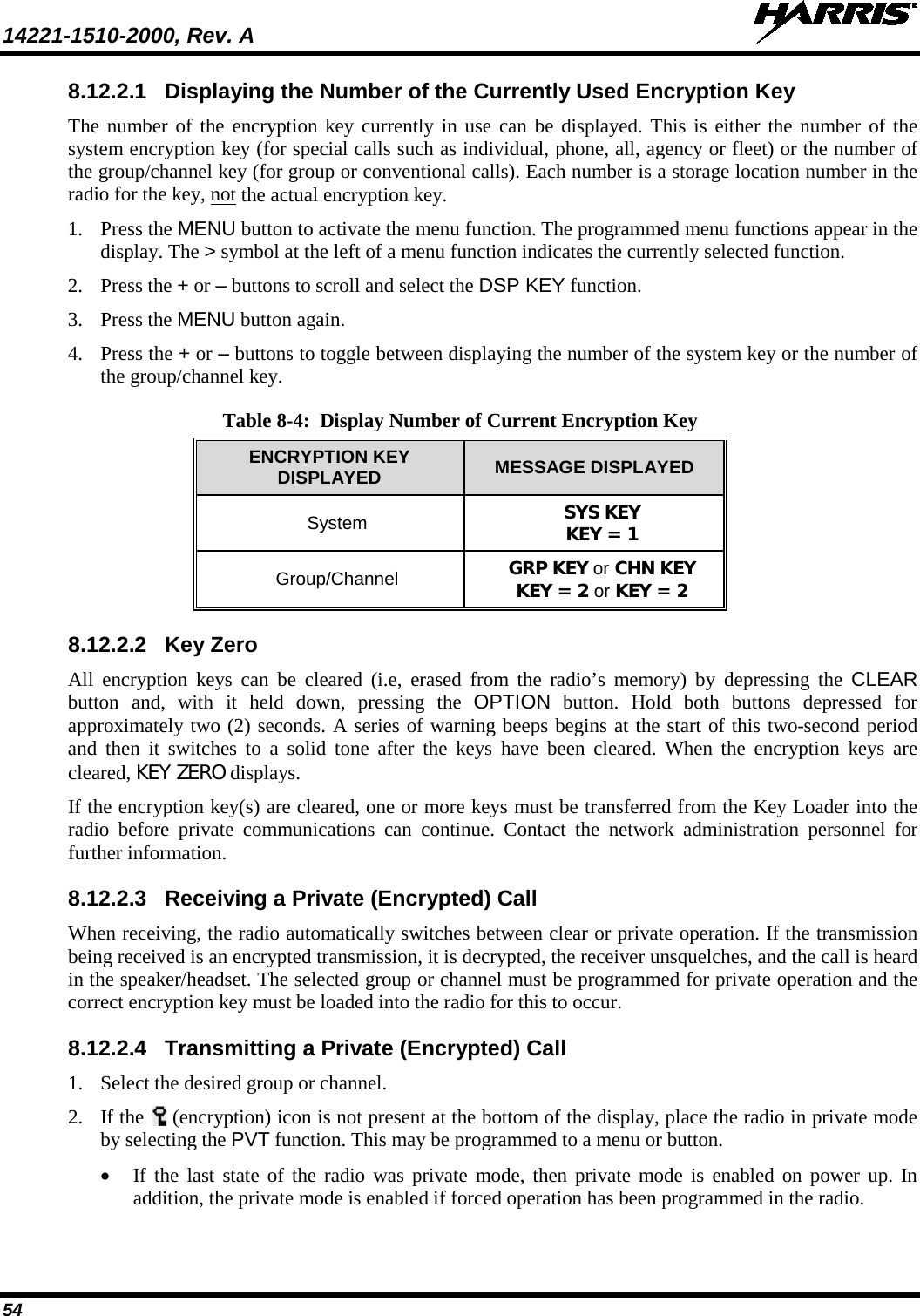
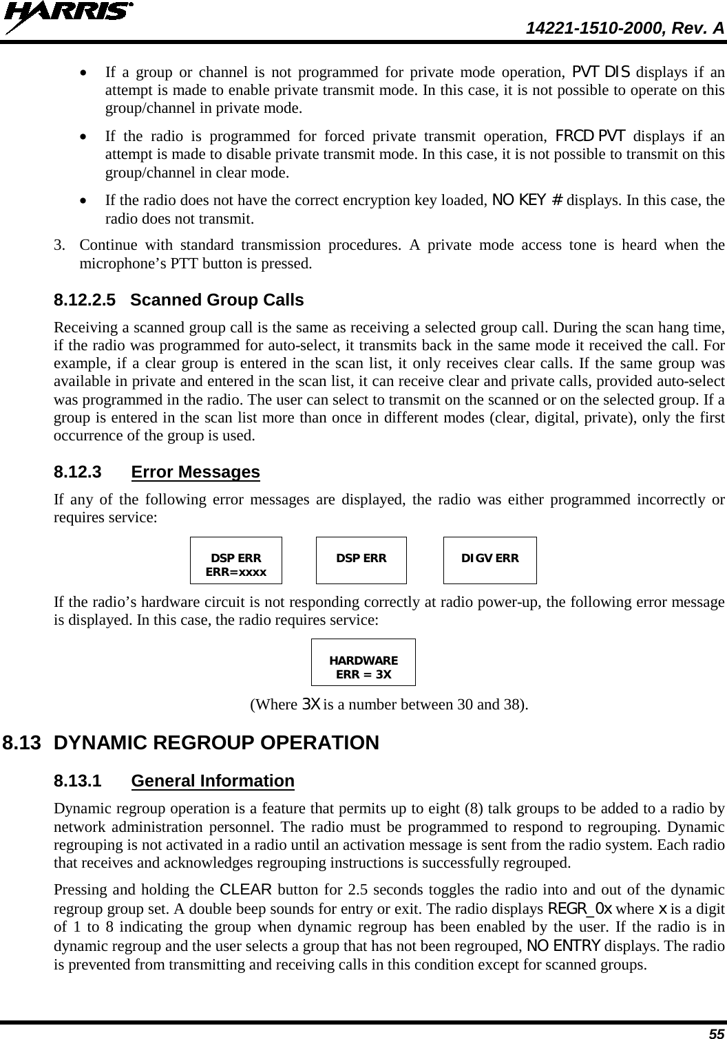
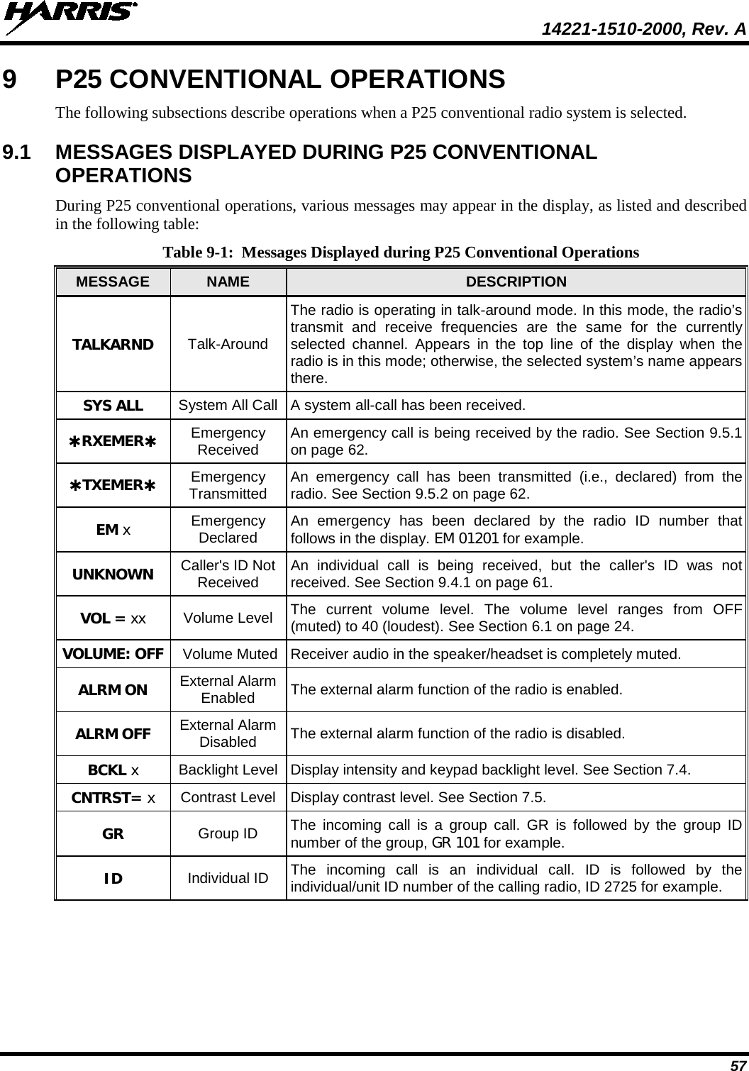
HARRIS CORPORATION XG-25M 700/800 MHz 35W 14221 1510 2000 Rev A XG 25M Mobile Radio
HARRIS >
Contents
- 1. User Manual 1
- 2. User Manual 2
- 3. User Manual 3
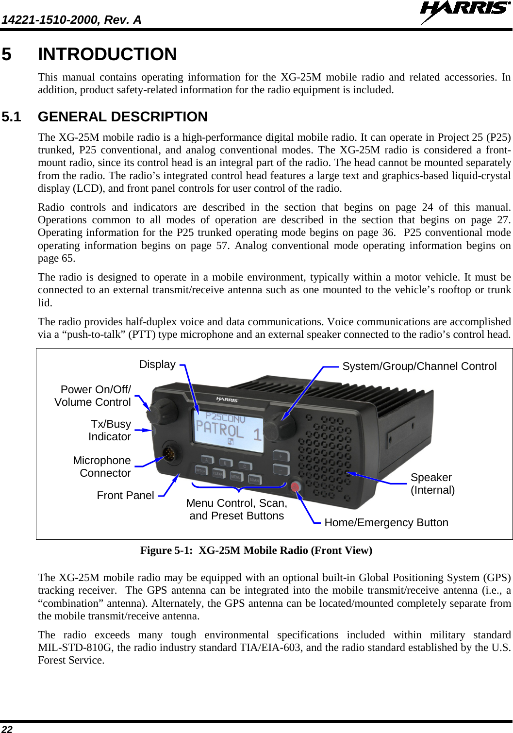
User Manual 1