HARRIS TR-0076-E XG-25M 700/800 MHz 35W User Manual 14221 1510 2000 Rev A XG 25M Mobile Radio
HARRIS CORPORATION XG-25M 700/800 MHz 35W 14221 1510 2000 Rev A XG 25M Mobile Radio
HARRIS >
Contents
- 1. User Manual 1
- 2. User Manual 2
- 3. User Manual 3
User Manual 1

Operator’s Manual
14221-1510-2000
Rev. A, May/13
XG-25M Mobile Radios
50-Watt VHF, 136 to 174 MHz
14015-0010-01
and
35-Watt Dual-Band, 700/800 MHz
14015-0020-01

14221-1510-2000, Rev. A
2
MANUAL REVISION HISTORY
REV. DATE REASON FOR CHANGE
– Sep/12 Initial release.
A May/13 Added the 700/800 MHz radio and the respective MPE distance information
. Added
Programmable Button Functions section and Button Remapping sections.
Harris Corporation, Public Safety and Professional Communications (PSPC) Business, continually evaluates its technical
publications for completeness, technical accuracy, and organization. You can assist in this process by submitting your
comments and suggestions to the following:
Harris Corporation fax your comments to: 1-434-455-6851
PSPC Business or
Technical Publications e-mail us at: PSPC_TechPubs@harris.com
221 Jefferson Ridge Parkway
Lynchburg, VA 24501 ACKNOWLEDGEMENT
This device is made under license under one or more of the following US patents: 4,590,473; 4,636,791; 5,148,482;
5,185,796; 5,271,017; 5,377,229; 4,716,407; 4,972,460; 5,502,767; 5,146,497; 5,164,986; 5,185,795; 5,226,084; 5,247,579;
5,491,772; 5,517,511; 5,630,011; 5,649,050; 5,701,390; 5,715,365; 5,754,974; 5,826,222; 5,870,405; 6,161,089; and
6,199,037 B1. DVSI claims certain rights, including patent rights under aforementioned U.S. patents, and under other U.S.
and foreign patents and patents pending. Any use of this software or technology requires a separate written license from
DVSI. CREDITS
Harris, assuredcommunications are registered trademarks of Harris Corporation.
AMBE is a registered trademark and IMBE, AMBE+, and AMBE+2 are trademarks of Digital Voice Systems, Inc.
All other brand and product names are trademarks, registered trademarks, or service marks of their respective holders.
NOTICE!
The material contained herein is subject to U.S. export approval. No export or re-export is permitted without written
approval from the U.S. Government. Rated: EAR99 in accordance with U.S. Dept. of Commerce regulations 15CFR774,
Export Administration Regulations.
Information and descriptions contained herein are the property of Harris Corporation. Such information and descriptions may
not be copied or reproduced by any means, or disseminated or distributed without the express prior written permission of
Harris Corporation, PSPC Business, 221 Jefferson Ridge Parkway, Lynchburg, VA 24501.
The voice coding technology embodied in this product is protected by intellectual property rights including patent rights,
copyrights, and trade secrets of Digital Voice Systems, Inc. The user of this technology is explicitly prohibited from
attempting to decompile, reverse engineer, or disassemble the Object Code, or in any other way convert the Object Code into
human-readable form.
Repairs to this equipment should be made only by an authorized service technician or facility designated by the supplier. Any
repairs, alterations or substitutions of recommended parts made by the user to this equipment not approved by the
manufacturer could void the user's authority to operate the equipment in addition to the manufacturer's warranty.
This product conforms to the European Union WEEE Directive 2002/96/EC. Do not dispose of this product in a
public landfill. Take it to a recycling center at the end of its life.
This manual is published by Harris Corporation without any warranty. Improvements and changes to this manual necessitated by typographical errors,
inaccuracies of current information, or improvements to programs and/or equipment, may be made by Harris Corporation
at any time and without notice.
Such changes will be incorporated into new editions of this manual. No part of this manual may be reproduced or transmitted in any
form or by any means,
electronic or mechanical, including photocopying and recording, for any purpose, without the express written permission of
Harris Corporation.
Copyright© 2012 — 2013, Harris Corporation

14221-1510-2000, Rev. A
3
TABLE OF CONTENTS
Section Page
1 SAFETY SYMBOL CONVENTIONS ......................................................................................... 7
2 RF ENERGY EXPOSURE INFORMATION ............................................................................. 7
2.1 RF ENERGY EXPOSURE AWARENESS AND CONTROL INFORMATION FOR FCC
OCCUPATIONAL USE REQUIREMENTS........................................................................................ 7
2.1.1 Federal Communications Commission Regulations ............................................................... 8
2.2 COMPLIANCE WITH RF EXPOSURE STANDARDS ...................................................................... 8
2.2.1 Mobile Antennas .................................................................................................................. 11
2.2.2 Approved Accessories .......................................................................................................... 12
2.2.3 Contact Information .............................................................................................................. 12
3 OPERATION SAFETY RECOMMENDATIONS ................................................................... 12
3.1 OCCUPATIONAL SAFETY GUIDELINES AND SAFETY TRAINING INFORMATION ........... 12
3.2 TRANSMITTER HAZARDS ............................................................................................................. 12
3.3 SAFE DRIVING RECOMMENDATIONS ........................................................................................ 13
3.4 OPERATING RULES AND REGULATIONS .................................................................................. 14
3.5 OPERATING TIPS ............................................................................................................................. 14
3.6 RADIO FREQUENCY INTERFERENCE ......................................................................................... 15
3.6.1 FCC Part 15 .......................................................................................................................... 15
3.6.2 Industry Canada .................................................................................................................... 15
4 MARITIME FREQUENCIES .................................................................................................... 16
5 INTRODUCTION ........................................................................................................................ 22
5.1 GENERAL DESCRIPTION ............................................................................................................... 22
5.2 RELATED PUBLICATIONS ............................................................................................................. 23
5.3 REPLACEMENT PARTS .................................................................................................................. 23
6 CONTROLS AND INDICATORS ............................................................................................. 24
6.1 POWER ON/OFF/VOLUME CONTROL .......................................................................................... 24
6.2 SYSTEM/GROUP/CHANNEL CONTROL ...................................................................................... 24
6.3 BUTTONS .......................................................................................................................................... 24
6.4 DISPLAY ........................................................................................................................................... 25
6.4.1 General Information ............................................................................................................. 25
6.4.2 Status Icons ........................................................................................................................... 25
6.4.3 Messages Displayed ............................................................................................................. 26
6.5 TRANSMIT/BUSY INDICATOR...................................................................................................... 26
6.6 ALERT TONES .................................................................................................................................. 26
7 COMMON OPERATIONS ......................................................................................................... 27
7.1 TURNING THE RADIO ON AND OFF AND ADJUSTING VOLUME ........................................... 27
7.2 CONNECTING A MICROPHONE (“MIC”) ..................................................................................... 27
7.3 LOCKING AND UNLOCKING THE FRONT PANEL BUTTONS ................................................. 27
7.4 DISPLAY AND BUTTON BACKLIGHT ADJUSTMENT ............................................................... 27
7.5 DISPLAY CONTRAST ADJUSTMENT ........................................................................................... 28
7.6 SYSTEM SELECTION ...................................................................................................................... 28
7.6.1 +/– Buttons Select System .................................................................................................... 28
7.6.2 System/Group/Channel Control Selects System ................................................................... 28
7.6.3 Selecting a System with the System Selection (SYS) Function ........................................... 28
7.7 GROUP/CHANNEL SELECTION .................................................................................................... 29
7.7.1 System/Group/Channel Control Selects Groups/Channels ................................................... 29
7.7.2 +/– Buttons Select Groups/Channels .................................................................................... 29

14221-1510-2000, Rev. A
4
(Continued)
TABLE OF CONTENTS
Section Page
7.7.3 Selecting a Group/Channel with the Group/Channel Selection (GRP) Function .................. 29
7.8 SELECTING A SYSTEM AND A GROUP/CHANNEL WITH THE SYSTEM/GROUP (SG)
FUNCTION ........................................................................................................................................ 30
7.9 TRANSMIT POWER LEVEL ADJUSTMENT ................................................................................. 30
7.9.1 Tx Power Adjustment via the Menu ..................................................................................... 30
7.9.2 Tx Power Adjustment via a Programmed Button ................................................................. 31
7.10 MENU OPERATIONS ....................................................................................................................... 31
7.11 FEATURE ENCRYPTION DISPLAY ............................................................................................... 33
7.11.1 General Information .............................................................................................................. 33
7.11.2 Accessing the Feature Encryption Display ........................................................................... 34
7.11.3 Serial ROM Number (12 Hexadecimal Digits) ..................................................................... 34
7.11.4 Feature Encryption Data Stream ........................................................................................... 34
7.11.5 Number Fields ...................................................................................................................... 34
7.11.6 Feature Numbers ................................................................................................................... 34
7.12 MACRO KEYS ................................................................................................................................... 35
8 TRUNKED OPERATIONS......................................................................................................... 36
8.1 MESSAGES DISPLAYED DURING TRUNKED OPERATIONS ................................................... 36
8.2 ALERT TONES DURING TRUNKED OPERATIONS ..................................................................... 39
8.3 GROUP CALLS ON A TRUNKED SYSTEM ................................................................................... 40
8.3.1 Receiving a Group Call ......................................................................................................... 40
8.3.2 Transmitting a Group Call .................................................................................................... 40
8.4 INDIVIDUAL CALLS ON A TRUNKED SYSTEM ......................................................................... 41
8.4.1 Receiving and Responding to an Individual Call .................................................................. 41
8.4.2 Sending an Individual Call ................................................................................................... 42
8.4.3 Call Storage Lists .................................................................................................................. 42
8.5 EMERGENCY OPERATIONS ON A TRUNKED SYSTEM ............................................................ 43
8.5.1 General Information .............................................................................................................. 43
8.5.2 Receiving an Emergency ...................................................................................................... 43
8.5.3 Declaring an Emergency ....................................................................................................... 43
8.5.4 Clearing an Emergency ......................................................................................................... 44
8.6 SYSTEM SCAN OPERATIONS ON A TRUNKED SYSTEM ......................................................... 44
8.6.1 General Information .............................................................................................................. 44
8.6.2 Wide Area System Scan ....................................................................................................... 44
8.6.3 ProScan ................................................................................................................................. 44
8.6.4 Priority System Scan ............................................................................................................. 45
8.6.5 Turning System Scan On and Off ......................................................................................... 45
8.7 GROUP SCAN OPERATIONS ON A TRUNKED SYSTEM ............................................................ 45
8.7.1 General Information .............................................................................................................. 45
8.7.2 Turning Scan On and Off ...................................................................................................... 46
8.7.3 Priority Group Scanning ....................................................................................................... 46
8.7.4 Adding Groups to the Scan List and Changing a Group’s Scan Priority .............................. 47
8.7.5 Deleting Groups from the Scan List ..................................................................................... 47
8.7.6 Nuisance Delete .................................................................................................................... 48
8.8 TELEPHONE INTERCONNECT CALL OPERATIONS ON A P25 TRUNKED SYSTEM ............ 48
8.8.1 Receiving a Telephone Interconnect Call ............................................................................. 48
8.8.2 Sending a Telephone Interconnect Call ................................................................................ 48
8.8.3 DTMF Overdial of Programmed Numbers ........................................................................... 49
8.9 MOBILE DATA ON A TRUNKED SYSTEM ................................................................................... 49
8.9.1 General Information .............................................................................................................. 49
8.9.2 Displays ................................................................................................................................ 50
8.9.3 Data Off Operation ............................................................................................................... 50
8.9.4 Data On Operation ................................................................................................................ 50

14221-1510-2000, Rev. A
5
(Continued)
TABLE OF CONTENTS
Section Page
8.9.5 Exiting Data Calls................................................................................................................. 50
8.9.6 Scan Lockout Mode .............................................................................................................. 51
8.9.7 Data Lockout Mode .............................................................................................................. 51
8.10 STATUS OPERATIONS ON A TRUNKED SYSTEM ..................................................................... 51
8.11 MESSAGE OPERATIONS ON A TRUNKED SYSTEM .................................................................. 52
8.12 DIGITAL VOICE AND ENCRYPTED DIGITAL VOICE OPERATIONS ...................................... 53
8.12.1 Clear Mode ........................................................................................................................... 53
8.12.2 Private Mode ........................................................................................................................ 53
8.12.3 Error Messages ..................................................................................................................... 55
8.13 DYNAMIC REGROUP OPERATION ............................................................................................... 55
8.13.1 General Information ............................................................................................................. 55
8.13.2 Emergency Operation ........................................................................................................... 56
8.14 PAGING OPERATIONS (P25 TRUNKED SYSTEMS ONLY) ........................................................ 56
9 P25 CONVENTIONAL OPERATIONS .................................................................................... 57
9.1 MESSAGES DISPLAYED DURING P25 CONVENTIONAL OPERATIONS ................................ 57
9.2 ALERT TONES DURING P25 CONVENTIONAL OPERATIONS ................................................. 60
9.3 GROUP CALLS ON A P25 CONVENTIONAL SYSTEM ................................................................ 60
9.3.1 Receiving a Group Call ........................................................................................................ 60
9.3.2 Transmitting a Group Call .................................................................................................... 60
9.4 INDIVIDUAL CALLS ON A P25 CONVENTIONAL SYSTEM...................................................... 61
9.4.1 Receiving and Responding to an Individual Call ................................................................. 61
9.4.2 Transmitting an Individual Call ............................................................................................ 62
9.5 EMERGENCY GROUP CALLS ON A P25 CONVENTIONAL SYSTEM ...................................... 62
9.5.1 Receiving an Emergency Group Call ................................................................................... 62
9.5.2 Declaring an Emergency on a Group .................................................................................... 62
9.5.3 Clearing an Emergency ........................................................................................................ 62
9.6 STATUS OPERATIONS ON A P25 CONVENTIONAL SYSTEM .................................................. 63
9.7 MESSAGE OPERATIONS ON A P25 CONVENTIONAL SYSTEM .............................................. 63
10 ANALOG CONVENTIONAL OPERATIONS ......................................................................... 65
10.1 MESSAGES DISPLAYED DURING ANALOG CONVENTIONAL OPERATIONS ..................... 65
10.2 ALERT TONES DURING ANALOG CONVENTIONAL OPERATIONS ...................................... 67
10.3 RECEIVING A CALL ON AN ANALOG CONVENTIONAL SYSTEM ......................................... 67
10.4 TRANSMITTING A CALL ON AN ANALOG CONVENTIONAL SYSTEM ................................ 67
10.5 SCANNING CHANNELS ON AN ANALOG CONVENTIONAL SYSTEM................................... 68
10.5.1 Turning Scan On and Off ..................................................................................................... 68
10.5.2 Adding Channels to the Scan List ........................................................................................ 69
10.5.3 Deleting Channels from the Scan List .................................................................................. 70
10.5.4 Nuisance Delete .................................................................................................................... 70
10.6 SQUELCH ADJUSTMENT FOR AN ANALOG CONVENTIONAL SYSTEM .............................. 70
10.7 TYPE 99 DECODING ON AN ANALOG CONVENTIONAL SYSTEM ......................................... 71
10.7.1 General Information ............................................................................................................. 71
10.7.2 Turning Type 99 Decoding On and Off ............................................................................... 72
10.7.3 Type 99 With or Without Channel Guard ............................................................................ 73
10.7.4 Resetting Type 99 After a Decoded Call .............................................................................. 73
10.7.5 Type 99 Disable After Radio PTT ........................................................................................ 73
10.8 MDC-1200 SIGNALING ON AN ANALOG CONVENTIONAL SYSTEM .................................... 73
10.8.1 Transmission (Encode) ......................................................................................................... 73
10.8.2 Receive (Decode) ................................................................................................................. 74
10.9 EMERGENCY CALLS ON AN ANALOG CONVENTIONAL SYSTEM ....................................... 74
10.9.1 G-STAR Emergency Signaling ............................................................................................ 74
10.9.2 5-Tone Emergency Signalling .............................................................................................. 74

14221-1510-2000, Rev. A
6
(Continued)
TABLE OF CONTENTS
Section Page
10.9.3 Tone Encode Transmission ................................................................................................... 75
11 PROGRAMMABLE FUNCTIONS ............................................................................................ 76
11.1 PROGRAMMABLE BUTTONS ........................................................................................................ 76
11.2 PROGRAMMABLE MENUS ............................................................................................................ 76
11.3 LIST OF FUNCTIONS ....................................................................................................................... 76
12 BUTTON REMAPPING ............................................................................................................. 80
13 CUSTOMER SERVICE .............................................................................................................. 81
13.1 CUSTOMER CARE ........................................................................................................................... 81
13.2 TECHNICAL ASSISTANCE ............................................................................................................. 81
14 WARRANTY REGISTRATION ................................................................................................ 82
15 WARRANTY ................................................................................................................................ 83
LIST OF TABLES Page
Table 2-1: Recommended Minimum Safe Lateral Distance from Transmitting Antenna Connected to a 136
to 174 MHz XG-25M Mobile Radio .............................................................................................. 9
Table 2-2: Recommended Minimum Safe Lateral Distance from a Transmitting Antenna Connected to a
700/800 MHz XG-25M Mobile Radio ........................................................................................... 9
Table 4-1: Maritime Frequencies ......................................................................................................................... 16
Table 6-1: Button Functions ................................................................................................................................ 24
Table 6-2: Status Icons ........................................................................................................................................ 25
Table 7-1: Menus for All Operating Modes ........................................................................................................ 31
Table 7-2: ECP Feature Numbers ........................................................................................................................ 35
Table 8-1: Messages Displayed during Trunked Operations ............................................................................... 36
Table 8-2: Alert Tones during Trunked Operations ............................................................................................ 39
Table 8-4: Display Number of Current Encryption Key ...................................................................................... 54
Table 9-1: Messages Displayed during P25 Conventional Operations ................................................................ 57
Table 9-2: Alert Tones during P25 Conventional Operations ............................................................................. 60
Table 10-1: Messages Displayed during Analog Conventional Operations ........................................................ 65
Table 10-2: Alert Tones during Analog Conventional Operations ...................................................................... 67
LIST OF FIGURES
Page
Figure 5-1: XG-25M Mobile Radio (Front View) ............................................................................................... 22
Figure 6-1: XG-25M Display (Generalized)........................................................................................................ 25
14221-1510-2000, Rev. A
7
1 SAFETY SYMBOL CONVENTIONS
The following conventions are used in this manual to alert the user to general safety precautions that must
be observed during all phases of operation, installation, service, and repair of this product. Failure to
comply with these precautions or with specific warnings elsewhere violates safety standards of design,
manufacture, and intended use of the product. Harris Corporation assumes no liability for the customer’s
failure to comply with these standards.
WARNING
The WARNING symbol calls attention to a procedure, practice, or the like, which,
if not correctly performed or adhered to, could result in personal injury. Do not
proceed beyond a WARNING symbol until the conditions identified are fully
understood or met.
CAUTION
The CAUTION symbol calls attention to an operating procedure, practice, or the like,
which, if not performed correctly or adhered to, could result in damage to the
equipment or severely degrade equipment performance.
NOTE
The NOTE symbol calls attention to supplemental information, which may improve
system performance or clarify a process or procedure.
2 RF ENERGY EXPOSURE INFORMATION
2.1 RF ENERGY EXPOSURE AWARENESS AND CONTROL
INFORMATION FOR FCC OCCUPATIONAL USE REQUIREMENTS
Before using the two-way mobile radio, review the following important RF energy awareness and
control information and operational instructions. Comply with this information and instructions in
order to ensure compliance with RF exposure guidelines.
This
radio is intended for use in occupational/controlled conditions, where users
have full knowledge of their exposure and can exercise control over their
exposure to remain below RF exposure limits. This radio is NOT authorized for
general population, consumer, or any other use.
Changes or modifications not expressly approved by Harris
could void the user's
authority to operate the equipment.
This two-way radio uses electromagnetic energy in the radio frequency (RF) spectrum to provide
communications between two or more users over a distance. It uses RF energy or radio waves to send and
receive calls. RF energy is one form of electromagnetic energy. Other forms include, but are not limited
to, electric power, sunlight, and x-rays. RF energy, however, should not be confused with these other
forms of electromagnetic energy, which, when used improperly, can cause biological damage. Very high
levels of x-rays, for example, can damage tissues and genetic material.
Experts in science, engineering, medicine, health, and industry work with organizations to develop
standards for exposure to RF energy. These standards provide recommended levels of RF exposure for
both workers and the general public. These recommended RF exposure levels include substantial margins
WARNING
CAUTION

14221-1510-2000, Rev. A
8
of protection. All two-way radios marketed in North America are designed, manufactured, and tested to
ensure they meet government-established RF exposure levels. In addition, manufacturers also recommend
specific operating instructions to users of two-way radios. These instructions are important because they
inform users about RF energy exposure and provide simple procedures on how to control it. Refer to the
following websites for more information on what RF energy exposure is and how to control exposure to
assure compliance with established RF exposure limits:
http://www.fcc.gov/oet/rfsafety/rf-faqs.html
http://www.osha.gov./SLTC/radiofrequencyradiation/index.html
2.1.1 Federal Communications Commission Regulations
Before it was marketed in the United States, the XG-25M two-way mobile radio was tested to ensure
compliance with FCC RF energy exposure limits for two-way mobile radios. When two-way radios are
used as a consequence of employment, the FCC requires users to be fully aware of and able to control
their exposure to meet occupational requirements. Exposure awareness can be facilitated by the use of a
label directing users to specific user awareness information. The radio has an RF exposure product label.
Also, the Product Safety Manual and this Operator’s Manual include information and operating
instructions required to control RF exposure and to satisfy compliance requirements.
2.2 COMPLIANCE WITH RF EXPOSURE STANDARDS
The XG-25M two-way mobile radio is designed and tested to comply with a number of national and
international standards and guidelines regarding human exposure to RF electromagnetic energy. This
radio complies with the IEEE and ICNIRP exposure limits for occupational/controlled RF exposure
environment at duty-cycle times of up to 50% (50% transmit, 50% receive), and it is authorized by the
FCC for occupational use. In terms of measuring RF energy for compliance with the FCC exposure
guidelines, the radio’s antenna radiates measurable RF energy only while it is transmitting (talking), not
when it is receiving (listening), or in a standby mode.
The XG-25M two-way mobile radio complies with the following RF energy exposure standards and
guidelines:
• United States Federal Communications Commission (FCC), Code of Federal Regulations; 47 CFR
§ 2 sub-part J.
• American National Standards Institute (ANSI)/Institute of Electrical and Electronic Engineers (IEEE)
C95.1-2005.
• Institute of Electrical and Electronic Engineers (IEEE) C95.1-2005.
• IC Standard RSS-102, Issue 2, 2005: Spectrum Management and Telecommunications Radio
Standards Specification. Radiofrequency Exposure Compliance of Radiocommunication Apparatus
(All Frequency Bands).
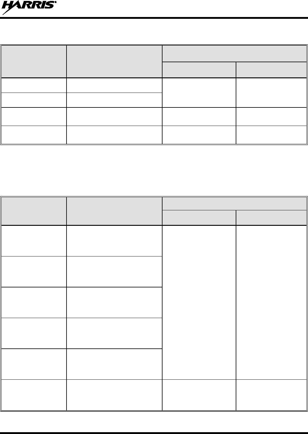
Table 2-1 and Table 2-2
list the recommended minimum safe lateral distances for a
controlled environment and for unaware bystanders in an uncontrolled environment,
from transmitting antennas (i.e., monopoles over a ground plane, or dipoles) at rated
radio power for mobile radios installed in a vehicle. Transmit only when unaware
bystanders are at least the uncontrolled recommended minimum safe lateral distance
away from the transmitting antenna.
Based on the highest radiated RF power and the highest antenna gain in antennas to be used with
XG-25M, the distances listed in Table 2-1 (for the 136 to 174 MHz radio) and Table 2-2 (for the
700/800 MHz radio) are considered as safe distances for controlled and uncontrolled environments with
the XG-25M mobile radio transmitting at a maximum 50% duty cycle:
CAUTION
14221-1510-2000, Rev. A
9
Table 2-1: Recommended Minimum Safe Lateral Distance from Transmitting Antenna
Connected to a 136 to 174 MHz XG-25M Mobile Radio
ANTENNA
ELEMENT PART
NUMBER ANTENNA DESCRIPTION
RECOMMENDED MINIMUM LATERAL HUMAN BODY
DISTANCE FROM TRANSMITTING ANTENNA
CONTROLLED
ENVIRONMENT
UNCONTROLLED
ENVIRONMENT
AN-225002-001 136 to 174 MHz, 0 dBd Gain 24.8 Inches
(63 Centimeters) 55.1 Inches
(140 Centimeters)
AN-225006-001 132 to 960 MHz, 0 dBd Gain
AN-225002-003 136 to 174 MHz, 3 dBd Gain 35.0 Inches
(89 Centimeters) 78.0 Inches
(198 Centimeters)
AN-225002-004 136 to 174 MHz, 2.4 dBd Gain 32.7 Inches
(83 Centimeters) 72.8 Inches
(185 Centimeters)
Table 2-2: Recommended Minimum Safe Lateral Distance from a Transmitting Antenna
Connected to a 700/800 MHz XG-25M Mobile Radio
ANTENNA
PART NUMBER ANTENNA DESCRIPTION
RECOMMENDED MINIMUM LATERAL HUMAN BODY
DISTANCE FROM TRANSMITTING ANTENNA
CONTROLLED
ENVIRONMENT
UNCONTROLLED
ENVIRONMENT
AN-125001-002
(mount) with
AN-225001-001
(element)
700/800 MHz Standard
Rooftop-Mount;
3 dBd Gain
9.8 Inches
(25 Centimeters) 21.7 Inches
(55 Centimeters)
AN-125001-002
(mount) with
AN-225001-002
(element)
700/800 MHz Standard
Rooftop-Mount;
Elevated-Feed 3 dBd Gain
AN-125001-002
(mount) with
AN-225001-003
(element)
700/800 MHz Standard
Rooftop-Mount;
Elevated-Feed, No Ground Plane
3 dBd Gain
AN-125001-002
(mount) with
AN-225001-004
(element)
700/800 MHz Standard
Rooftop-Mount;
Low-Profile 2 dBd Gain
AN-125001-002
(mount) with
AN-225006-001
(element)
132 to 960 MHz, ¼-Wavelength;
Standard Rooftop-Mount;
0 dBd Gain; Field-Tuned
AN-125001-002
(mount) with
AN-225001-005
(element)
700/800 MHz Standard
Rooftop-Mount;
5 dBd Gain
12.6 Inches
(32 Centimeters) 28.3 Inches
(72 Centimeters)
(Table Continued on Next Page)

14221-1510-2000, Rev. A
10
Table 2-2: Recommended Minimum Safe Lateral Distance from a Transmitting Antenna
Connected to a 700/800 MHz XG-25M Mobile Radio
ANTENNA
PART NUMBER ANTENNA DESCRIPTION
RECOMMENDED MINIMUM LATERAL HUMAN BODY
DISTANCE FROM TRANSMITTING ANTENNA
CONTROLLED
ENVIRONMENT
UNCONTROLLED
ENVIRONMENT
AN-125001-004
(mount) with
AN-225001-001
(element)
700/800 MHz Thick
Rooftop-Mount;
3 dBd Gain
9.8 Inches
(25 Centimeters) 21.7 Inches
(55 Centimeters)
AN-125001-004
(mount) with
AN-225001-002
(element)
700/800 MHz Thick
Rooftop-Mount;
Elevated-Feed 3 dBd Gain
AN-125001-004
(mount) with
AN-225001-003
(element)
700/800 MHz Thick
Rooftop-Mount;
Elevated-Feed, No Ground Plane
3 dBd Gain
AN-125001-004
(mount) with
AN-225001-004
(element)
700/800 MHz Thick
Rooftop-Mount;
Low-Profile 2 dBd Gain
AN-125001-004
(mount) with
AN-225006-001
(element)
132 to 960 MHz, ¼-Wavelength;
Thick Rooftop-Mount;
0 dBd Gain; Field-Tuned
AN-125001-004
(mount) with
AN-225001-005
(element)
700/800 MHz Thick
Rooftop-Mount;
5 dBd Gain
12.6 Inches
(32 Centimeters) 28.3 Inches
(72 Centimeters)
AN-125001-006
(mount) with
AN-225001-001
(element)
700/800 MHz GPS Combo
Rooftop-Mount;
3 dBd / 5.15 dBi Gain
9.8 Inches
(25 Centimeters) 21.7 Inches
(55 Centimeters)
AN-125001-006
(mount) with
AN-225001-002
(element)
700/800 MHz GPS Combo
Rooftop-Mount;
Elevated-Feed 3 dBd Gain
AN-125001-006
(mount) with
AN-225001-003
(element)
700/800 MHz GPS Combo
Rooftop-Mount;
Elevated-Feed, No Ground Plane
3 dBd Gain
AN-125001-006
(mount) with
AN-225001-004
(element)
700/800 MHz GPS Combo
Rooftop-Mount;
Low-Profile 2 dBd Gain
AN-125001-006
(mount) with
AN-225006-001
(element)
132 to 960 MHz, ¼-Wavelength;
Combo Rooftop-Mount;
0 dBd Gain; Field-Tuned
(Table Continued on Next Page)

14221-1510-2000, Rev. A
11
Table 2-2: Recommended Minimum Safe Lateral Distance from a Transmitting Antenna
Connected to a 700/800 MHz XG-25M Mobile Radio
ANTENNA
PART NUMBER ANTENNA DESCRIPTION
RECOMMENDED MINIMUM LATERAL HUMAN BODY
DISTANCE FROM TRANSMITTING ANTENNA
CONTROLLED
ENVIRONMENT
UNCONTROLLED
ENVIRONMENT
AN-125001-006
(mount) with
AN-225001-005
(element)
700/800 MHz GPS Combo
Rooftop-Mount;
5 dBd / 7.15 dBi Gain
12.6 Inches
(32 Centimeters) 28.3 Inches
(72 Centimeters)
AN-125001-008
(mount) with
AN-225001-001
(element)
700/800 MHz Magnetic-Mount;
3 dBd Gain
9.8 Inches
(25 Centimeters) 21.7 Inches
(55 Centimeters)
AN-125001-008
(mount) with
AN-225001-002
(element)
700/800 MHz Magnetic-Mount;
Elevated-Feed 3 dBd Gain
AN-125001-008
(mount) with
AN-225001-003
(element)
700/800 MHz Magnetic-Mount;
Elevated-Feed, No Ground Plane
3 dBd Gain
AN-125001-008
(mount) with
AN-225001-004
(element)
700/800 MHz Magnetic-Mount;
Low-Profile 2 dBd Gain
AN-125001-008
(mount) with
AN-225006-001
(element)
132 to 960 MHz, ¼-Wavelength;
Magnetic-Mount Rooftop-Mount;
0 dBd Gain; Field-Tuned
AN-125001-008
(mount) with
AN-225001-005
(element)
700/800 MHz Magnetic-Mount;
5 dBd Gain 12.6 Inches
(32 Centimeters) 28.3 Inches
(72 Centimeters)
AN102800V1
(Discontinued)
136 to 941 MHz, ¼-Wavelength*,
Standard Rooftop-Mount;
0 dBd Gain
9.8 Inches
(25 Centimeters) 21.7 Inches
(55 Centimeters)
STI-Co
CCAS-SB-700
760 - 820 MHz Concealed Peal-
and-Stick Internal-Mount;
0 dBi Gain
7.9 Inches
(20 Centimeters) 19.7 Inches
(50 Centimeters)
2.2.1 Mobile Antennas
The antenna(s) for the radio must be installed in accordance with procedures presented in the Product
Safety Manual and in the Installation Manual. Installation is limited to a metal-body motor vehicle or
vehicles with appropriate ground planes.
Use only approved/supplied antenna(s) or an approved replacement antenna. Unauthorized antennas,
modifications, or attachments can cause the FCC RF exposure limits to be exceeded.

14221-1510-2000, Rev. A
12
2.2.2 Approved Accessories
The radio has been tested and meets FCC RF guidelines when used with accessories supplied or
designated for use with it. Use of other accessories may not ensure compliance with the FCC’s RF
exposure guidelines, and may violate FCC regulations. For a list of approved accessories refer to the
Installation Manual and/or the Harris Products and Services Catalog.
Always use Harris authorized accessories (antennas, speaker/mics, etc). Use of
unauthorized accessories may cause the FCC Occupational/Controlled Exposure
RF compliance requirements to be exceeded.
2.2.3 Contact Information
For additional information on RF exposure and other information, contact Harris using one of the contact
links listed in Section 13.
3 OPERATION SAFETY RECOMMENDATIONS
3.1 OCCUPATIONAL SAFETY GUIDELINES AND SAFETY TRAINING
INFORMATION
To ensure bodily exposure to RF electromagnetic energy is within the FCC allowable limits for
occupational use. Always adhere to the following basic guidelines:
• The push-to-talk button should only be depressed when intending to send a voice message.
• The radio should only be used for necessary work-related communications.
• The radio should only be used by authorized and trained personnel. It should never be operated by
children.
• Do not attempt any unauthorized modification to the radio. Changes or modifications to the radio may
cause harmful interference and/or cause it to exceed FCC RF exposure limits. Only qualified
personnel should service the radio.
• Always use only authorized accessories (antennas, control heads, speakers/mics, etc.). Use of
unauthorized accessories can cause the FCC RF exposure compliance requirements to be exceeded.
The information listed above provides the user with information needed to make him or her aware of a RF
exposure, and what to do to assure that this radio operates within the FCC exposure limits of this radio.
3.2 TRANSMITTER HAZARDS
The operator of any mobile radio should be aware of certain hazards common to
the operation of vehicular radio transmissions. Possible hazards include but are
not limited to:
• Explosive Atmospheres — Just as it is dangerous to fuel a vehicle while its engine is running, be
sure to turn the radio OFF while fueling the vehicle. If the radio is mounted in the trunk of the
vehicle, DO NOT carry containers of fuel in the trunk.
WARNING
WARNING

14221-1510-2000, Rev. A
13
Areas with potentially explosive atmosphere are often, but not always, clearly marked. Turn the radio
OFF when in any area with a potentially explosive atmosphere. It is rare, but not impossible that the
radio or its accessories could generate sparks.
• Interference To Vehicular Electronic Systems — Electronic fuel injection systems, electronic anti-
skid braking systems, electronic cruise control systems, etc., are typical of the types of electronic
devices that can malfunction due to the lack of protection from radio frequency (RF) energy present
when transmitting. If the vehicle contains such equipment, consult the dealer for the make of vehicle
and enlist their aid in determining if such electronic circuits perform normally when the radio is
transmitting.
• Electric Blasting Caps — To prevent accidental detonation of electric blasting caps, DO NOT use
two-way radios within 1000 feet (305 meters) of blasting operations. Always obey the “Turn Off
Two-Way Radios” (or equivalent) signs posted where electric blasting caps are being used. (OSHA
Standard: 1926.900).
• Radio Frequency Energy — To prevent burns or related physical injury from radio frequency
energy, do not operate the transmitter when anyone outside of the vehicle is within the minimum safe
distance from the antenna as specified in Table 2-1. Refer to Section 2.1 for additional information.
• Vehicles Powered By Liquefied Petroleum (LP) Gas — Radio installation in vehicles powered by
liquefied petroleum gas, where the LP gas container is located in the trunk or other sealed-off space
within the interior of the vehicle, must conform to the National Fire Protection Association standard
NFPA 58. This requires:
The space containing the radio equipment must be isolated by a seal from the space containing
the LP gas container and its fittings.
Outside filling connections must be used for the LP gas container.
The LP gas container space shall be vented to the outside of the vehicle.
• Vehicles Equipped with Airbags — For driver and passenger safety, avoid mounting the radio’s
control head (or any other component) above or near airbag deployment areas. In addition to driver-
side and passenger-side front-impact airbags, some vehicles may also be equipped with side-impact
airbags. For occupant safety, verify the location of all airbags within the vehicle before installing the
radio equipment.
3.3 SAFE DRIVING RECOMMENDATIONS
The American Automobile Association (AAA) advocates the following key safe driving recommenda-
tions:
• Read the literature on the safe operation of the radio.
• Keep both hands on the steering wheel and the microphone in its hanger whenever the vehicle is in
motion.
• Place calls only when the vehicle is stopped.
• When talking from a moving vehicle is unavoidable, drive in the slower lane. Keep conversations
brief.
• If a conversation requires taking notes or complex thought, stop the vehicle in a safe place and
continue the call.
• Whenever using a mobile radio, exercise caution.
14221-1510-2000, Rev. A
14
3.4 OPERATING RULES AND REGULATIONS
Two-way radio systems must be operated in accordance with the rules and regulations of the local,
regional, or national government.
In the United States, the XG-25M mobile radio must be operated in accordance with the rules and
regulations of the Federal Communications Commission (FCC). Operators of two-way radio equipment
must be thoroughly familiar with the rules that apply to the particular type of radio operation. Following
these rules helps eliminate confusion, assures the most efficient use of the existing radio channels, and
results in a smoothly functioning radio network.
When using a two-way radio, remember these rules:
• It is a violation of FCC rules to interrupt any distress or emergency message. The radio operates in
much the same way as a telephone “party line.” Therefore, always listen to make sure the channel is
clear before transmitting. Emergency calls have priority over all other messages. If someone is
sending an emergency message – such as reporting a fire or asking for help in an accident, do not
transmit unless assistance can be offered.
• The use of profane or obscene language is prohibited by Federal law.
• It is against the law to send false call letters or false distress or emergency messages. The FCC
requires keeping conversations brief and confined to business. Use coded messages whenever
possible to save time.
• Using the radio to send personal messages (except in an emergency) is a violation of FCC rules. Send
only essential messages.
• It is against Federal law to repeat or otherwise make known anything overheard on the radio.
Conversations between others sharing the channel must be regarded as confidential.
• The FCC requires self-identification at certain specific times by means of call letters. Refer to the
rules that apply to the particular type of operation for the proper procedure.
• No changes or adjustments shall be made to the equipment except by an authorized or certified
electronics technician.
Under U.S. law, operation of an unlicensed radio transmitter within the jurisdiction of
the United States may be punishable by a fine of up to $10,000, imprisonment for up to
two (2) years, or both.
3.5 OPERATING TIPS
The following conditions tend to reduce the effective range of two-way radios and should be avoided
whenever possible:
• Operating the radio in areas of low terrain, or while under power lines or bridges.
• Obstructions such as mountains and buildings.
In areas where transmission or reception is poor, communication improvement may
sometimes be obtained by moving a few yards in another direction, or moving to a
higher elevation.
CAUTION
NOTE

14221-1510-2000, Rev. A
15
3.6 RADIO FREQUENCY INTERFERENCE
3.6.1 FCC Part 15
This device complies with Part 15 of the FCC Rules. Operation is subject to the following two conditions:
1. This device may not cause harmful interference; and,
2. This device must accept any interference received, including interference that may cause undesired
operation.
3.6.2 Industry Canada
This device complies with Industry Canada license-exempt RSS standard(s). Operation is subject to the
following two conditions: (1) this device may not cause interference, and (2) this device must accept any
interference, including interference that may cause undesired operation of the device.
Le présent appareil est conforme aux CNR d'Industrie Canada applicables aux appareils radio exempts de
licence. L'exploitation est autorisée aux deux conditions suivantes : (1) l'appareil ne doit pas produire de
brouillage, et (2) l'utilisateur de l'appareil doit accepter tout brouillage radioélectrique subi, même si le
brouillage est susceptible d'en compromettre le fonctionnement.
14221-1510-2000, Rev. A
16
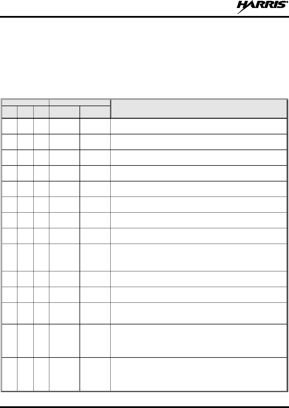
4 MARITIME FREQUENCIES
Refer to Table 4-1 for a list of maritime frequencies per United States Coast Guard (USCG), National
Oceanic and Atmospheric Administration (NOAA), and Canadian Department Fisheries and Oceans.
• United States (US)
• International (Intl)
• Canada (CA)
Table 4-1: Maritime Frequencies
CHANNEL
FREQUENCY
CHANNEL USAGE
US INTL CA
SHIP
(MHz)
SHORE
(MHz)
1
1
T: 156.05
R: 160.65
T: 160.65
R: 156.05
International: Public Correspondence, Port Operations.
1a T/R:
156.05
T/R:
156.05
US: Port Operations and Commercial, Vessel Traffic Service (VTS). New
Orleans/Lower Mississippi area.
2
2
T: 156.10
R: 160.70
T: 160.70
R: 156.10
International: Public Correspondence, Port Operations.
3 3 T: 156.15
R: 160.75
T: 160.75
R: 156.15
International: Public Correspondence, Port Operations.
4
T: 156.20
R: 160.80
T: 160.80
R: 156.20
International: Public Correspondence, Port Operations.
4a T/R:
156.20
T/R:
156.20
Canada: Department Fisheries Ocean (DFO)/Canadian Coast Guard only in
British Columbia coast area. Commercial fishing in east coast area.
5
T: 156.25
R: 160.85
T: 160.85
R: 156.25
International: Public Correspondence, Port Operations.
5a
5a
T/R:
156.25
T/R:
156.25
US: Port Operations or VTS in Houston, New Orleans and Seattle areas.
6
6
6
T/R:
156.30
T/R:
156.30
US: Intership Safety.
International: Intership.
Canada: May be used for search and rescue communications between
ships and aircraft.
7
T: 156.35
R: 160.95
T: 160.95
R: 156.35
International: Public Correspondence, Port Operations.
7a 7a T/R:
156.35
T/R:
156.35
US: Commercial.
8
8
8
T/R:
156.40
T/R:
156.40
US: Commercial (Intership only).
International: Intership.
Canada: Also assigned for intership in the Lake Winnipeg area.
9 9 9 T/R:
156.45 T/R:
156.45 US: Boater Calling. Commercial and Non-Commercial.
International: Intership, Port Operations.
Canada: Commercial - British Columbia coast area.
May be used to communicate with aircraft and helicopters in predominantly
maritime support operations.
10
10
10
T/R:
156.50
T/R:
156.50
US: Commercial.
International: Intership, Port Operations.
Canada: Commercial - British Columbia coast area.
May also be used for communications with aircraft engaged in coordinated
search and rescue and antipollution operations.

14221-1510-2000, Rev. A
17
Table 4-1: Maritime Frequencies
CHANNEL
FREQUENCY
CHANNEL USAGE
US INTL CA
SHIP
(MHz)
SHORE
(MHz)
11
11
11
T/R:
156.55
T/R:
156.55
US: Commercial. VTS in selected areas.
International: Port Operations.
Canada: VTS - British Columbia coast area.
Also used for pilotage purposes.
12
12
12
T/R:
156.60
T/R:
156.60
US: Port Operations. VTS in selected areas.
International: Port Operations.
Canada: VTS - British Columbia coast area.
Also used for pilotage purposes.
13 13 13 T/R:
156.65 T/R:
156.65 US: Intership Navigation Safety (Bridge-to-bridge). Ships >20m length
maintain a listening watch on this channel in US waters.
International: Intership, Port Operations.
Canada: VTS - British Columbia coast area.
Also used for pilotage purposes.
14
14
14
T/R:
156.70
T/R:
156.70
US: Port Operations. VTS in selected areas.
International: Port Operations.
Canada: VTS - British Columbia coast area.
Also used for pilotage purposes.
15
15
15
T/R:
156.75
(US: Rx
Only)
T/R:
156.75
US: Environmental (Receive only). Used by Class C Emergency Position-
Indicating Radio Beacons (EPIRBs).
International: Intership, Port Operations.
Canada: Port operations and Ship Movement - British Columbia coast area.
All operations limited to 1-watt maximum power. May also be used for on-
board communications.
16
16
16
T/R:
156.80
T/R:
156.80
US: International Distress, Safety and Calling. Ships required to carry radio,
US Coast Guard (USCG), and most coast stations maintain a listening
watch on this channel.
International: International Distress, Safety and Calling.
Canada: International Distress, Safety and Calling.
17 17 17 T/R:
156.85 T/R:
156.85 US: State Control.
International: Intership, Port Operations.
Canada: Port operations and Ship Movement - British Columbia coast area.
All operations limited to 1 watt maximum power. May also be used for on-
board communications.
18
T: 156.90
R: 161.50
T: 161.50
R: 156.90
International: Public Correspondence, Port Operations.
18a
18a
T/R:
156.90
T/R:
156.90
US: Commercial.
Canada: Towing - British Columbia coast area.
19
T: 156.95
R: 161.55*
T: 161.55*
R: 156.95
International: Public Correspondence, Port Operations.
19a
19a
T/R:
156.95
T/R:
156.95
US: Commercial.
Canada: DFO/Canadian Coast Guard. Pacific Pilots - British Columbia
coast area.
20
20
20
T: 157.00
R: 161.60
T: 161.60
R: 157.00
US: Port Operations (Duplex).
International: Public Correspondence, Port Operations.
Canada: Port operations only with 1 watt maximum power.
20a
T/R:
157.00
T/R:
157.00
US: Port Operations.

14221-1510-2000, Rev. A
18
Table 4-1: Maritime Frequencies
CHANNEL
FREQUENCY
CHANNEL USAGE
US INTL CA
SHIP
(MHz)
SHORE
(MHz)
21
T: 157.05
R: 161.65*
T: 161.65*
R: 157.05
International: Public Correspondence, Port Operations.
21a 21a T/R:
157.05
T/R:
157.05
US: US Coast Guard only.
Canada: DFO/Canadian Coast Guard only.
21b
- -
T/R:
161.65
Canada: Continuous Marine Broadcast (CMB) service (weather).
22 T: 157.10
R: 161.70
T: 161.70
R: 157.10
International: Public Correspondence, Port Operations.
22a
22a
T/R:
157.10
T/R:
157.10
US: Coast Guard Liaison and Maritime Safety Information Broadcasts.
Broadcasts announced on channel 16.
Canada: For communications between Canadian Coast Guard and non-
Canadian Coast Guard stations only.
23
23
T: 157.15
R: 161.75
T: 161.75
R: 157.15
International: Public Correspondence, Port Operations.
23a T/R:
157.15
T/R:
157.15
US: US Coast Guard only.
23b
- -
T/R:
161.75
Canada: Continuous Marine Broadcast (CMB) service (weather).
24 24 24 T: 157.20
R: 161.80
T: 161.80
R: 157.20
US: Public Correspondence (Marine Operator).
International: Public Correspondence, Port Operations.
25
25
25
T: 157.25
R: 161.85
T: 161.85
R: 157.25
US: Public Correspondence (Marine Operator).
International: Public Correspondence, Port Operations.
Canada: Also assigned for operations in the Lake Winnipeg area.
25b T/R:
161.85
Canada: Continuous Marine Broadcast (CMB) service (weather).
26
26
26
T: 157.30
R: 161.90
T: 161.90
R: 157.30
US: Public Correspondence (Marine Operator).
International: Public Correspondence, Port Operations.
27 27 27 T: 157.35
R: 161.95
T: 161.95
R: 157.35
US: Public Correspondence (Marine Operator).
International: Public Correspondence, Port Operations.
28
28
28
T: 157.40
R: 162.00
T: 162.00
R: 157.40
US: Public Correspondence (Marine Operator).
International: Public Correspondence, Port Operations.
28b - - T/R:
162.00
Canada: Continuous Marine Broadcast (CMB) service (weather).
60
60
T: 156.025
R: 160.625
T: 160.625
R: 156.025
International: Public Correspondence, Port Operations.
61
T: 156.075
R: 160.675
T: 160.675
R: 156.075
International: Public Correspondence, Port Operations.
61a
T/R:
156.075
T/R:
156.075
Canada: DFO/Canadian Coast Guard only in British Columbia coast area.
62
T: 156.125
R: 160.725
T: 160.725
R: 156.125
International: Public Correspondence, Port Operations.
62a T/R:
156.125
T/R:
156.125
Canada: DFO/Canadian Coast Guard only in British Columbia coast area.

14221-1510-2000, Rev. A
19
Table 4-1: Maritime Frequencies
CHANNEL
FREQUENCY
CHANNEL USAGE
US INTL CA
SHIP
(MHz)
SHORE
(MHz)
63
T: 156.175
R: 160.775
T: 160.775
R: 156.175
International: Public Correspondence, Port Operations.
63a 63a T/R:
156.175 T/R:
156.175 US: Port Operations and Commercial, VTS. New Orleans/Lower Mississippi
area.
Canada: Tow Boats - British Columbia coast area.
64
64
T: 156.225
R: 160.825
T: 160.825
R: 156.225
International: Public Correspondence, Port Operations.
64a
T/R:
156.225
T/R:
156.225
Canada: Commercial fishing only.
65
T: 156.275
R: 160.875
T: 160.875
R: 156.225
International: Public Correspondence, Port Operations.
65a
65a
T/R:
156.275
T/R:
156.275
US: Port Operations.
Canada: Search and rescue and antipollution operations on the Great
Lakes. Towing on the Pacific Coast. Port operations only in the
St. Lawrence River areas with 1 watt maximum power. Intership in inland
Manitoba, Saskatchewan, and Alberta areas.
66
T: 156.325
R: 160.925
T: 160.925
R: 156.325
International: Public Correspondence, Port Operations.
66a 66a T/R:
156.325 T/R:
156.325 US: Port Operations.
Canada: Port operations only in the St. Lawrence River/Great Lakes areas
with 1 watt maximum power. 1 watt marina channel - British Columbia coast
area.
67
67
67
T/R:
156.375
T/R:
156.375
US: Commercial. Used for Bridge-to-bridge communications in lower Miss.
River. Intership only.
International: Intership, Port Operations.
Canada: May also be used for communications with aircraft engaged in
coordinated search and rescue and antipollution operations. Commercial
fishing only in east coast and inland Manitoba, Saskatchewan, and Alberta
areas. Pleasure craft - British Columbia coast area.
68
68
68
T/R:
156.425
T/R:
156.425
US: Non-Commercial.
International: Port Operations.
Canada: For marinas, yacht clubs and pleasure craft.
69
69
69
T/R:
156.475
T/R:
156.475
US: Non-Commercial.
International: Intership, Port Operations.
Canada: Commercial fishing only - east coast area.
Pleasure craft - British Columbia coast area.
70
70
70
T/R:
156.525
T/R:
156.525
US: Digital Selective Calling (voice communications not allowed).
International: Digital selective calling for distress, safety and calling.
Canada: Digital selective calling for distress, safety and calling.
71
71
71
T/R:
156.575
T/R:
156.575
US: Non-Commercial.
International: Port Operations.
Canada: Ship Movement - British Columbia coast area. Marinas and yacht
clubs - east coast and on Lake Winnipeg.
72
72
72
T/R:
156.625
T/R:
156.625
US: Non-Commercial (Intership only).
International: Intership.
Canada: May be used to communicate with aircraft and helicopters in
predominantly maritime support operations.
Pleasure craft - British Columbia coast area.

14221-1510-2000, Rev. A
20
Table 4-1: Maritime Frequencies
CHANNEL
FREQUENCY
CHANNEL USAGE
US INTL CA
SHIP
(MHz)
SHORE
(MHz)
73
73
73
T/R:
156.675
T/R:
156.675
US: Port Operations.
International: Intership, Port Operations.
Canada: May also be used for communications with aircraft engaged in
coordinated search and rescue and antipollution operations. Commercial
fishing only in east coast and inland Manitoba, Saskatchewan, and Alberta
areas.
74
74
74
T/R:
156.725
T/R:
156.725
US: Port Operations.
International: Port Operations.
Canada: VTS and Ship Movement British Columbia coast area.
75
75
T/R:
156.775
T/R:
156.775
International: Port Operations.
Canada: Simplex port operation, ship movement and navigation related
communication only. 1 watt maximum.
76 76 T/R:
156.825 T/R:
156.825 International: Port Operations.
Canada: Simplex port operation, ship movement and navigation related
communication only. 1 watt maximum.
77
77
77
T/R:
156.875
T/R:
156.875
US: Port Operations (Intership only).
International: Intership.
Canada: Pilotage - British Columbia coast area; 25 watts. Port operations
only in the St. Lawrence River/Great Lakes areas with 1 watt maximum
power.
78
T: 156.925
R: 161.525
T: 161.525
R: 156.925
International: Public Correspondence, Port Operations.
78a 78a T/R:
156.925
T/R:
156.925
US: Non-Commercial.
Canada: Fishing Industry - British Columbia coast area.
79
T: 156.975
R: 161.575
T: 161.575
R: 156.975
International: Public Correspondence, Port Operations.
79a
79a
T/R:
156.975
T/R:
156.975
US: Commercial. Non-Commercial in Great Lakes only.
Canada: Fishing Industry - British Columbia coast area.
80 T: 157.025
R: 161.625
T: 161.625
R: 157.025
International: Public Correspondence, Port Operations.
80a
80a
T/R:
157.025
T/R:
157.025
US: Commercial. Non-Commercial in Great Lakes only.
Canada: Fishing Industry - British Columbia coast area.
81 T: 157.075
R: 161.675
T: 161.675
R: 157.075
International: Public Correspondence, Port Operations.
81a
81a
T/R:
157.075
T/R:
157.075
US: US Government only - Environmental protection operations.
Canada: DFO/Canadian Coast Guard use only.
82 T: 157.125
R: 161.725
T: 161.725
R: 157.125
International: Public Correspondence, Port Operations.
82a
82a
T/R:
157.125
T/R:
157.125
US: US. Government only.
Canada: DFO/Canadian Coast Guard use only.
83
T: 157.175
R: 161.775
T: 161.775
R: 157.175
International: Public Correspondence, Port Operations.
83a
83a
T/R:
157.175
T/R:
157.175
US: US Coast Guard only.
Canada: DFO/Canadian Coast Guard and other Government agencies.
83b
- -
T/R:
161.775
Canada: Continuous Marine Broadcast (CMB) service (weather).
14221-1510-2000, Rev. A
21
Table 4-1: Maritime Frequencies
CHANNEL
FREQUENCY
CHANNEL USAGE
US INTL CA
SHIP
(MHz)
SHORE
(MHz)
84
84
84
T: 157.225
R: 161.825
T: 161.825
R: 157.225
US: Public Correspondence (Marine Operator).
International: Public Correspondence, Port Operations.
85 85 85 T: 157.275
R: 161.875
T: 161.875
R: 157.275
US: Public Correspondence (Marine Operator).
International: Public Correspondence, Port Operations.
86
86
86
T: 157.325
R: 161.925
T: 161.925
R: 157.325
US: Public Correspondence (Marine Operator).
International: Public Correspondence, Port Operations.
87 T/R:
157.375
T/R:
157.375
US: Public Correspondence (Marine Operator).
87
87
T: 157.375
R: 161.975
T: 161.975
R: 157.375
International: Port Operations.
Canada: Port operation and ship movement - east coast area.
Pleasure craft - British Columbia coast area.
AIS1
87b
T/R:
161.975
T/R:
161.975
US: Automatic Identification System.
Canada: Automatic Ship Identification and Surveillance System.
88
88
T: 157.425
R: 162.025
T: 162.025
R: 157.425
US: Commercial, Intership only.
International: Port Operations.
Canada: Port operation and ship movement - British Columbia coast area.
88a
T/R:
157.425
T/R:
157.425
US: Commercial, Intership only.
Canada: Automatic Ship Identification and Surveillance System.
88b T/R:
162.025
T/R:
162.025
Automatic Identification System.
WX1
WX1
R: 162.55
Weather Channel 1 (receive only).
WX2
WX2
R: 162.4
Weather Channel 2 (receive only).
WX3
WX3
R: 162.475
Weather Channel 3 (receive only).
WX4
R: 162.425
Weather Channel 4 (receive only).
WX5
R: 162.45
Weather Channel 5 (receive only).
WX6
R: 162.5
Weather Channel 6 (receive only).
WX7
R: 162.525
Weather Channel 7 (receive only).
14221-1510-2000, Rev. A
22
5 INTRODUCTION
This manual contains operating information for the XG-25M mobile radio and related accessories. In
addition, product safety-related information for the radio equipment is included.
5.1 GENERAL DESCRIPTION
The XG-25M mobile radio is a high-performance digital mobile radio. It can operate in Project 25 (P25)
trunked, P25 conventional, and analog conventional modes. The XG-25M radio is considered a front-
mount radio, since its control head is an integral part of the radio. The head cannot be mounted separately
from the radio. The radio’s integrated control head features a large text and graphics-based liquid-crystal
display (LCD), and front panel controls for user control of the radio.
Radio controls and indicators are described in the section that begins on page 24 of this manual.
Operations common to all modes of operation are described in the section that begins on page 27.
Operating information for the P25 trunked operating mode begins on page 36. P25 conventional mode
operating information begins on page 57. Analog conventional mode operating information begins on
page 65.
The radio is designed to operate in a mobile environment, typically within a motor vehicle. It must be
connected to an external transmit/receive antenna such as one mounted to the vehicle’s rooftop or trunk
lid.
The radio provides half-duplex voice and data communications. Voice communications are accomplished
via a “push-to-talk” (PTT) type microphone and an external speaker connected to the radio’s control head.
Figure 5-1: XG-25M Mobile Radio (Front View)
The XG-25M mobile radio may be equipped with an optional built-in Global Positioning System (GPS)
tracking receiver. The GPS antenna can be integrated into the mobile transmit/receive antenna (i.e., a
“combination” antenna). Alternately, the GPS antenna can be located/mounted completely separate from
the mobile transmit/receive antenna.
The radio exceeds many tough environmental specifications included within military standard
MIL-STD-810G, the radio industry standard TIA/EIA-603, and the radio standard established by the U.S.
Forest Service.
Power On/Off/
Volume Control
Microphone
Connector
Tx/Busy
Indicator
Speaker
(Internal)
Home/Emergency Button
Menu Control, Scan,
and Preset Buttons
Front Panel
System/Group/Channel Control
Display

14221-1510-2000, Rev. A
23
The radio supports the P25 Common Air Interface (P25 CAI) standard. P25 radio systems utilize
Improved Multi-Band Excitation (IMBE) speech and data compression technology, developed by Digital
Voice Systems, Inc.
Harris recommends the buyer use only an authorized representative to install and
service this product. The warranties provided to the buyer under the terms of sale shall
be null and void if this product is installed or serviced improperly, and Harris shall have
no further obligation to the buyer for any damage caused to the product or to any person
or personal property.
5.2 RELATED PUBLICATIONS
The following publications contain additional information about the XG-25M mobile radio:
•
Quick Guide: 14221-1510-1000
•
Product Safety Manual:
14221-1510-4000
•
Installation Manual: 14221-1510-4440
•
Maintenance Manual, VHF
14221-1510-5000
• Maintenance Manual, 700/800 MHz 14221-1510-5020
The Quick Guide and the Product Safety Manual are included with each mobile radio equipment package
when it ships from the factory. This Operator’s Manual and the Quick Guide are available on-line at
www.pspc.harris.com/Mobile/XG-25M.asp without a login. All XG-25M mobile radio manuals and the
Quick Guide can be obtained from www.pspc.harris.com via an Information Center login (i.e., a user
name and password are required). The manuals are in Tech Link’s Technical Manual Library.
5.3 REPLACEMENT PARTS
Replacement parts can be ordered via our Customer Care center. To order replacement parts, call, fax or
e-mail:
United States:
• Phone Number: 1-800-368-3277
• Fax Number: 1-321-409-4393
• E-mail: PSPC_CustomerFocus@harris.com
International:
• Phone Number: 1-434-455-6403
• Fax Number: 321-409-4394
• E-mail: PSPC_InternationalCustomerFocus@harris.com
CAUTION
14221-1510-2000, Rev. A
24
6 CONTROLS AND INDICATORS
This section describes the controls and indicators located on the XG-25M radio’s front panel.
6.1 POWER ON/OFF/VOLUME CONTROL
The radio’s Power On/Off/Volume control is located on the top-left corner of its front panel. See Figure
5-1 on page 22. To turn on the radio, rotate this control clockwise out of the detent position. To turn the
radio off, rotate this control fully counter-clockwise until it returns to the detent position, as sensed by a
click of the control. See Section 7.1 for additional information.
6.2 SYSTEM/GROUP/CHANNEL CONTROL
The radio’s System/Group/Channel control is located just to the right of the display, as viewing the front
panel. See Figure 5-1 on page 22. With default radio programming, rotating this control selects groups or
channels. It selects groups if the currently selected radio system is a P25 trunked radio system. It selects
channels if the currently selected radio system is a conventional system (P25 conventional or analog
conventional). For a P25 conventional radio system, the radio can be programmed to display either the
channel name or the respective group name.
The radio may be programmed so this control selects radio systems instead of groups/channels. In this
case, the + (plus) and – (minus) buttons are normally programmed to select groups/channels.
6.3 BUTTONS
Ten buttons are located on the front panel of the radio. Button functions are summarized in Table 6-1.
Table 6-1: Button Functions
BUTTON FUNCTION
MENU Primary Function:
Accesses the menu. This is a list of addition features that are not available
directly from the keypad.
Secondary Function: Activates a selected function within the menu, similar to an “Enter” key.
+ and – Primary Function: Scrolls through available radio
systems, groups, or channels, depending on
radio programming. Selects radio systems with default programming.
Secondary Function: Changes the selection to another function a menu list.
CLEAR
When the menu function is active, press this button to cancel the menu operation,
remove all
displays associated with the menu, and return to the previous display.
When operating in conventional mode, press this button briefly to disable radio receiver
squelch, so activity on the selected channel can be monitored. When pressed and held for
approximately three (3) seconds, this button toggles conventional channel decoding (Channel
Guard, Digital Channel Guard, T99) on and off, if programmed for the selected channel.
OPTION Activates a programmable option per radio programming. For example, high or low
radio
transmitter power.
SCAN
Toggles scan operation on and off.
A, B and C The A, B and C preset buttons are programmed for one of many available functions. In this
case, the function is activated by pressing the respective preset button.
Home/Emergency button. If programmed as a home button, when pressed, the radio will
immediately transition to a programmed home radio system and group/channel.
If programmed as an emergency
button, hold it depressed for a short time to initiate and
transmit an emergency call request. The exact depression time is programmable. See Section
s
8.5 (P25 trunked) and/or 10.9 (analog conventional) for additional information.
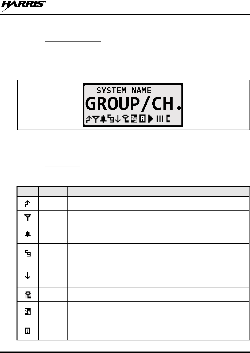
14221-1510-2000, Rev. A
25
6.4 DISPLAY
6.4.1 General Information
The XG-25M radio has a tough high-contrast alphanumeric liquid-crystal display (LCD) that indicates
radio status and various operations. See Figure 5-1. When not in a menu selection mode, two text lines in
the upper and middle portion of the display indicate the name of the currently selected radio system and
group/channel. Status icons in the lower portion turn on to indicate various functions are active/enabled.
During menu operations, the display lists programmed menu functions.
Figure 6-1: XG-25M Display (Generalized)
The radio’s display and buttons are backlit. Backlight intensity and display contrast adjustments can be
performed according to the procedures in Sections 7.4 and 7.5 respectively.
6.4.2 Status Icons
Status icons that appear in the bottom of the radio’s display are summarized in Table 6-2.
Table 6-2: Status Icons
ICON NAME STATUS/MEANING
Transmit
Icon The radio is transmitting. Also when transmitting, the Tx/Busy
indicator located on
the radio’s front panel lights red.
Busy Icon The group/channel is “busy” (i.e., the radio is receiving a call
on the
group/channel).
Type 99
Icon
The selected analog channel has Type 99 (T99) signaling on/enabled.
See
Section 10.7 on page 71 for additional information. If this icon is not present, Type
99 signaling is off/disabled.
Channel
Guard Icon
The selected analog channel has receive Channel Guard (CG) signaling enabled.
If this icon is not present, receive Channel Guard signaling
on the selected
channel is disabled (i.e., not programmed).
Low
Transmit
Power Icon
The radio is set to transmit in low power mode.
High/Low transmit power level is
adjustable on a per radio system basis for trunked systems and on a per
channel
basis for conventional systems. See Section 7.9 on page 30
for additional
information.
Encryption
Icon
The radio is set to transmit and receive encrypted voice calls. Clear voice
(unencrypted) voice calls can also be received.
P25 Icon A Project 25 (P25) radio system and group/channel are selected.
The radio is
operating in P25 mode. For operating information, see Section 8 on page 36
(P25
trunked) or Section 9 on page 57 (P25 conventional).
Analog
Channel
Icon
An analog conventional radio
system and channel are selected The radio is
operating in an analog conventional mode. See Section 10 on page 65
for
operating information.
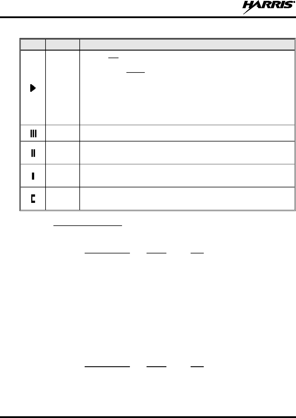
14221-1510-2000, Rev. A
26
Table 6-2: Status Icons
ICON NAME STATUS/MEANING
Scan Icon
When on with animated rotation, scan mode is enabled. The radio is scanning
groups on the list, including the Priority 1 and Priority 2 groups.
When on steady without animated rotation, scan is temporarily disabled because
the radio is receiving a call on a scanned group.
When off (i.e., icon not appearing in the display), scan is disabled. The radio is not
scanning.
Information about scanning P25 trunked groups is included in Section 8.7
on page
45.
Information about scanning analog conventional channels is included in
Section
10.5 on page 68.
Scan Icon The selected group/channel is on the scan list as a non-priority group/channel
.
The group/channel will be scanned when the radio is scanning.
Scan
Priority 2
Icon
The selected group/channel is on the scan list as the Priority 2 group/channel.
When the radio is scanning, it will be scanned with second-highest priority.
Scan
Priority 1
Icon
The selected group/channel is on the scan list as the Priority 1 group/channel.
When the radio is scanning, it will be scanned with highest priority.
Special
Call Icon
This icon appears when the radio is in special call mode. See Section 8.4
on page
41 (P25 trunked) or Section 9.4 on page 61 (P25 conventional)
for additional
information.
6.4.3 Messages Displayed
During radio operations, various status messages can appear in the display. The messages are listed and
described in the respective sections of this manual as follows:
Operating Mode
Section
Page
P25 Trunked: 8.1 36
P25 Conventional:
9.1
57
Analog Conventional:
10.1
65
6.5 TRANSMIT/BUSY INDICATOR
As indicated in Figure 5-1, the radio’s Tx/Busy indicator is located on the left side of the radio’s front
panel. This indicator lights green when the radio is receiving a signal and it lights red when the radio is
transmitting.
6.6 ALERT TONES
The XG-25M mobile radio provides audible alert tones (“beeps”) to indicate various operating conditions.
The tones are listed and described in the respective sections of this manual as follows:
Operating Mode
Section
Page
P25 Trunked: 8.2 39
P25 Conventional:
9.2
60
Analog Conventional:
10.2
67

14221-1510-2000, Rev. A
27
7 COMMON OPERATIONS
7.1 TURNING THE RADIO ON AND OFF AND ADJUSTING VOLUME
To turn on the radio, rotate its Power On/Off/Volume control clockwise out of the detent position. Some
radio installations may be wired so an external switch such as the vehicle’s ignition key must also be
placed in a run or on position before the radio will turn on. When the radio is on, indications appear in the
display, such as the selected group/channel and status icons. The radio may be programmed to power-up
on the previously selected radio system and group/channel (that was selected at the last power down), or
to a pre-programmed radio system and group/channel. It may also be programmed to sound an audible
tone (“beep”) at turn on.
Rotate this control clockwise to increase the volume of receive audio and rotate it counter-clockwise to
decrease the volume. Volume adjustment can be made at anytime during radio operation, as needed.
To turn the radio off, rotate this control fully counter-clockwise until it clicks. The radio turns completely
off within a few seconds of this action.
7.2 CONNECTING A MICROPHONE (“MIC”)
As shown in Figure 5-1, the microphone connector is located near a bottom corner of the radio’s front
panel. Connect a microphone to this connector by positioning the small notch of the mic plug to a
straight-up (i.e., in the 12-oclock position) at the mic connector, and then gently push the plug into the
connector. Finally, latch the plug to the connector by rotating the plug’s locking ring in a clockwise
direction.
7.3 LOCKING AND UNLOCKING THE FRONT PANEL BUTTONS
Some buttons on the front panel can be disabled to prevent accidental activation by “locking” them.
Locking and unlocking is a toggle-type function. To lock the buttons:
1. Press the MENU button to activate the menu function.
2. Within one (1) second, press the OPTION button. LOCKED displays when the buttons lock.
To unlock the buttons, simply repeat the process. UNLOCKED displays when the buttons unlock.
Locking can also be performed with the KEY LOCK menu function, if this function is programmed on a
radio menu. See Section 7.10 for additional information.
Unlocking can only be performed with the MENU and OPTION buttons, as described above.
7.4 DISPLAY AND BUTTON BACKLIGHT ADJUSTMENT
If backlight adjustment function is programmed on a radio menu, backlight intensity level can be adjusted
as follows:
1. Press the MENU button to activate the menu function. The programmed menu functions appear in the
display. The > symbol at the left of a menu function indicates the currently selected function.
Alternately, if another button such as one (1) of the three (3) preset buttons is programmed with the
Backlight function, press this button and advance to step 4.
2. Press the + or – buttons to until BACKLGHT (for backlight) is selected.
3. Press the MENU button again to select the backlight menu.

14221-1510-2000, Rev. A
28
4. Press the + or – buttons to select a new backlight intensity level. Selections are OFF (no backlighting)
and 1 though 6, with 6 being the brightest backlight intensity level.
5. Press the MENU button again to save the new backlight intensity level and return to a normal
group/channel display indication.
7.5 DISPLAY CONTRAST ADJUSTMENT
If the contrast adjustment function is programmed on a radio menu, the display contrast level can be
adjusted as follows:
1. Press the MENU button to activate the menu function. The programmed menu functions appear in the
display. The > symbol at the left of a menu function indicates the currently selected function.
Alternately, if another button such as one (1) of the three (3) preset buttons is programmed with the
Contrast function, press this button and advance to step 4.
2. Press the + or – buttons to until CONTRAST is selected.
3. Press the MENU button again to select the contrast menu.
4. Press the + or – buttons to select a new contrast level between 1 and 8.
5. Press the MENU button again to save the new contrast level and return to a normal group/channel
display indication.
7.6 SYSTEM SELECTION
Several different radio system selection methods exists based upon radio programming.
7.6.1 +/– Buttons Select System
If the + and – buttons are programmed for radio system selection, when the radio is at a normal
group/channel display (i.e., not in a menu), press either button to select a different system. The name of
the selected system appears in the top line of the display, except during menu operations.
7.6.2 System/Group/Channel Control Selects System
If the System/Group/Channel control is programmed for radio system selection, rotate this control to
select a different system. The name of the selected system appears in the top line of the display, except
during menu operations.
7.6.3 Selecting a System with the System Selection (SYS) Function
If the System Selection (SYS) function is programmed to a radio button or menu, a different radio system
can be selected using one of the following methods. This function can be programmed to the trunked
menu or to the conventional menu or to both menus:
System Selection Function Programmed to a Menu
1. Press the MENU button to activate the menu function. The programmed menu functions appear in the
display. The > symbol at the left of a menu function indicates the currently selected function.
2. Press the + or – buttons to scroll until SYS is selected with the > symbol.
3. Press the MENU button again to select this function. SYS = x displays, where x is the number of the
currently selected radio system, as programmed into the radio.

14221-1510-2000, Rev. A
29
4. Press the + or – buttons to scroll and select another radio system, as programmed into the radio. The
radio system’s name appears in the top line of the display, and its number follows SYS =.
5. When the desired system is displayed, press the MENU button again to change to it. Optionally, wait
and the radio will automatically change to the displayed system.
To cancel out of this operation at anytime and return to the original system, press the CLEAR button.
System Selection Function Programmed to a Button
1. Press the button programmed with the System Selection function. SYS = x displays, where x is the
number of the currently selected radio system, as programmed into the radio.
2. Press the + or – buttons to scroll and select another radio system, as programmed into the radio. The
radio system’s name appears in the top line of the display, and its number follows SYS =.
3. When the desired system is displayed, press the MENU button again to change to it. Optionally, wait
and the radio will automatically change to the displayed system.
To cancel out of this operation at anytime and return to the original system, press the CLEAR button.
7.7 GROUP/CHANNEL SELECTION
Several different group/channel selection methods exists based upon radio programming.
7.7.1 System/Group/Channel Control Selects Groups/Channels
If the System/Group/Channel control is programmed for group/channel selection, rotate this control to
select a different group or channel. The name of the selected group/channel appears in the middle line of
the display in large characters.
7.7.2 +/– Buttons Select Groups/Channels
If the + and – buttons are programmed for group/channel selection and the radio is at a normal
group/channel display (i.e., not in a menu), press either button to select a different group/channel. The
name of the selected group/channel appears in the middle line of the display in large characters.
Any radio button may be programmed for system or group/channel selection. Consult
with the radio system’s network administration personnel for programming information
for a specific radio.
7.7.3 Selecting a Group/Channel with the Group/Channel Selection (GRP)
Function
If the Group/Channel Selection (GRP) function is programmed to a radio button or menu, a different
group or channel can be selected using one of the following methods. This function can be programmed
to the trunked menu or to the conventional menu or to both menus:
Group/Channel Selection Function Programmed to a Menu
1. Press the MENU button to activate the menu function. The programmed menu functions appear in the
display. The > symbol at the left of a menu function indicates the currently selected function.
2. Press the + or – buttons to scroll until GRP is selected with the > symbol.
3. Press the MENU button again to select this function. If operating on a trunked system, GRP = x
displays, where x is the number of the currently selected group, as programmed into the radio. If
NOTE

14221-1510-2000, Rev. A
30
operating on a conventional system, CHN = x displays, where x is the number of the currently
selected channel, as programmed into the radio.
4. Press the + or – buttons to scroll and select another group/channel, as programmed into the radio. The
group/channel name displays. During group selection, its number, as programmed, follows GRP =.
During channel selection its number, as programmed, follows CHN =.
5. When the desired group/channel is displayed, press the MENU button again to change to it.
Optionally, wait and the radio will automatically change to the displayed group/channel.
To cancel out of this operation at anytime and return to the original system, press the CLEAR button.
Group/Channel Selection Function Programmed to a Button
1. Press the button programmed with the Group/Channel Selection (GRP) function. If operating on a
trunked system, GRP = x displays, where x is the number of the currently selected group, as
programmed into the radio. If operating on a conventional system, CHN = x displays, where x is the
number of the currently selected channel, as programmed into the radio.
2. Press the + or – buttons to scroll and select another group/channel, as programmed into the radio. The
group/channel name displays. During group selection, its number, as programmed, follows GRP =.
During channel selection its number, as programmed, follows CHN =.
3. When the desired group/channel is displayed, press the MENU button again to change to it.
Optionally, wait and the radio will automatically change to the displayed group/channel.
To cancel out of this operation at anytime and return to the original system, press the CLEAR button.
7.8 SELECTING A SYSTEM AND A GROUP/CHANNEL WITH THE
SYSTEM/GROUP (SG) FUNCTION
The radio’s system/group selection function allows 1 of up to 16 programmed system and group/channel
combinations to be selected via a single button press or menu selection. This function can be programmed
to the trunked menu or to the conventional menu or to both menus. To change to the particular system and
group/channel, press the respective programmed button or select the desired system/group/channel
combination (SG1 through SG16) programmed on a menu.
7.9 TRANSMIT POWER LEVEL ADJUSTMENT
The radio has two transmit power levels: high and low. Using the low transmit power level, when
possible, can help reduce or prevent unnecessary radio interference on nearby radio frequencies.
If the TX POWER menu function is programmed into the radio, the radio’s transmit power level can be
switched between low and high as described in the following subsections. For a trunked radio system, the
power level is adjustable on a per-system basis. For a conventional radio system, the power level is
adjustable on a per-channel basis.
When the low transmit power level is selected, the status icon appears at the bottom of the display and
LOW PWR briefly appears at the top. When the high transmit power level is selected, the status icon
does not appear at the bottom of the display and HIGH PWR briefly appears at the top.
The previously set power level is maintained after a channel change and after a radio system change.
7.9.1 Tx Power Adjustment via the Menu
1. Press the MENU button to activate the menu function. The programmed menu functions appear in the
display. The > symbol at the left of a menu function indicates the currently selected function.
14221-1510-2000, Rev. A
31
2. Press the + or – buttons to scroll until TX POWER is selected with the > symbol.
3. Press the MENU button again to toggle the transmit power level to the other level. For example, if the
radio was in the high power level, it will change to a low power level.
7.9.2 Tx Power Adjustment via a Programmed Button
Any button on the radio’s front panel can be programmed to toggle the transmit power level when it is
pressed. For example, one of the three (3) preset buttons (A, B, or C) may be programmed with this
function. If so, press that button to toggle the power level between low and high. The status icon
displays when low transmit power level is selected. Consult with the radio system administration
personnel as necessary to determine which button is programmed with this function, if any.
7.10 MENU OPERATIONS
The radio’s menu function accesses features that are not directly available by a single button stroke. Menu
functions available and the order of menu functions are configurable via radio programming. There are
two menus—a trunked menu and a conventional menu. The trunked menu is active when a trunked radio
system (e.g., P25 trunked) is selected and the conventional menu is active when a conventional radio
system is selected. Each menu can have up to 20 different functions. Menu functions are listed and
described in Table 7-1.
After a radio power-up, the menu function that is at the top of the programmed menu list will always be
displayed first when the MENU button is pressed. Subsequent access to the menu will return the last
menu function that was shown in the display and cursor position. Basic menu operation:
1. Press the MENU button to activate the menu function. The programmed menu functions appear in the
display. The > symbol at the left of a menu function indicates the currently selected function.
The radio continues to receive and transmit as normal when the menu function is active.
2. Press the + or – buttons to scroll though the menu with the > symbol until the desired menu function
is selected, then press the MENU button again to select this function.
3. Press the + or – buttons to scroll though selections within this function.
4. When the desired selection is indicated, press the MENU button again to store this selection.
The TX POWER function
, when selected, toggles between high and low transmit
power. It does not use the + or – buttons nor is an additional press of the MENU button
required.
Table 7-1: Menus for All Operating Modes
MENU* FEATURE* SETTINGS NOTES
KEY LOCK Key/Button Lock Locked, Unlocked
Use to lock and unlock radio buttons. As a
short-cut (i.e., selecting this function
is not
necessary), press the MENU button then
within one (1) second, press the OPTION
button. Also see Section 7.3 on page 27.
BACKLGHT Backlight Level
Adjust Off and 1 to 6
Use to adjust the brightness level of display
and button backlighting. See Section 7.4
on
page 27.
NOTE
NOTE

14221-1510-2000, Rev. A
32
Table 7-1: Menus for All Operating Modes
MENU* FEATURE* SETTINGS NOTES
CONTRAST Display Contrast
Adjust
1 to 8 Use to set the display’s contrast level. See
Section 7.5 on page 28.
SCAN Scan On, Off Toggles group/channel scan on and off.
SCAN ADD
Once selected:
Proper scan icon
displayed.
Scan Add Toggle Sequence: Scan,
Priority 2, Priority 1 Adds the currently selected group/
channel to
the scan list.
SCAN DEL
Once selected:
Scan icon goes
out.
Scan Delete No Scan Deletes the currently selected group/
channel
from scan list.
SCAN A/D
When selected:
Toggles through
scan selections
Scan
Add/Delete
Toggle Sequence: Scan,
Priority 2, Priority 1,
(repeats)
Changes preset group/
channel to next scan
choice in scan list.
SCAN ADD
Press twice when
actively receiving;
three times when
not receiving. Scan
icon displayed.
Last Scanned
Group/Channel
Recall (none) Changes the currently selected group/-
channel to the last scanned group/channel.
SYS
Once selected:
SYS = n
System
Selection (number of desired
system)
Displays the radio system selected.
Press +
or –
buttons to select a different system, then
either wait a short time or press the MENU
button to switch to the that system.
GRP
Once selected:
GRP = n
or
CHN = n
Group
Selection (number of
desired group)
Displays the group/channel selected.
Press
+ or –
buttons to select a different
group/channel, then either wait a short time
or press the MENU button to switch to that
new group/channel.
S/G 1
through
S/G 16
System and
Group/Channel
Selection (as programmed) Instantly changes to the respective
radio
system and group/-channel.
HOME
Once selected:
Home Group/-
Channel
Displayed.
Home Group/
Channel
Selection (none) Changes to the group/
channel defined for the
home function.
PHONE Phone Call (See the respective
Telephone Interconnect
Calls section.)
Allows access to the
Telephone Interconnect
Call feature. The radio system must be
equipped with interconnect hardware.
INDV Individual Call (See the respective
Individual Call section.)
Allows access to the Individual Call feature.
Not available in analog conventional mode.
MUTE Mute On, Off
Toggles the receiver audio (i.e.,
speaker/headset) mute function on and off.
NO DATA No Data On, Off
Toggles the data feature on and off. Applies
to trunked radio systems only.

14221-1510-2000, Rev. A
33
Table 7-1: Menus for All Operating Modes
MENU* FEATURE* SETTINGS NOTES
SYS SCAN
Once selected:
SYSC ON or
SYSC OFF
System Scan
Enable/Disable On, Off Toggles System Scan feature on and off.
Applies to trunked radio systems only.
See
Section 8.6 on page 44.
TALKARND Talk-Around On, Off Toggles repeater talk-around opera
tion on
and off. Applies to conventional
radio
systems only.
SQUELCH
Once selected:
SQLCH = xx
Front Panel
Squelch
Adjustment 1 to 16
Allows adjustment of the radio’s receiver
squelch setting. Applies to conventional
radio
systems only.
T99 EN
Once selected:
T99 ON or
T99 OFF
Type 99 Decode On, Off Toggles T99 decoding on and off. Applies to
conventional radio systems only.
EXT SPKR
Once selected:
SPKR ON or
SPKR OFF
External
Speaker On, Off
Use to enable and disable an optional
external/remote
speaker connected to the
radio. This speaker could be located either
inside or outside of the vehicle.
TX POWER Transmitter
Power Level High, Low
Use to toggle the radio’s transmit power level
between high and low. When the low transmit
power level is selected, the
status icon
displays.
PAGE Radio Page (none)
Allows radio paging via the radio’s individual
call list or radio ID number. Applies to P25
trunked radio systems only. See Section 8.14
on page 56 for additional details.
PROGRAM Programming
Mode (enable/disable)
Puts the radio in programming mode. For
radio system administration use only.
REVISION Radio Revision
Information (No user selectable
settings)
Selects the information display to view.
Read-only information.
FEATURES
Once selected:
See Feature
Encryption Display
section
Feature
Encryption
Display
(Informational displays
only. No user selectable
settings)
Indicates current features pro
grammed into
the radio as well as certain information
required to add features to the radio. See
Section 7.11.
FCC MENU FCC Menu (Informational displays
only. No user selectable
settings)
Indicates various radio system engineering-
related parameters.
* If Programmed.
7.11 FEATURE ENCRYPTION DISPLAY
7.11.1 General Information
The Feature Encryption Display data is available from the FEATURES menu, if this menu is
programmed into the radio. The data in this display indicates current features programmed into the radio
as well as information required to add features to the radio. This includes:
• Serial ROM Number — Serial number of the radio’s Read-Only Memory (ROM).

14221-1510-2000, Rev. A
34
• Feature Encryption Data Stream — Used to enable various features.
• Number Fields — Defines various limits.
• Enabled Features — Indicates the number of each enabled feature.
7.11.2 Accessing the Feature Encryption Display
If it is programmed in a menu, access the Feature Encryption Display as follows:
1. Press the MENU button to activate the menu function. The programmed menu functions appear in the
display. The > symbol at the left of a menu function indicates the currently selected function.
2. Press the + or – buttons to scroll though the menu with the > symbol until FEATURES is selected.
3. Press the MENU button again. The display indicates the ROM serial number or the last chosen item
in the Feature Encryption Display since the radio was powered up.
4. Press the + button to scroll from the beginning of the display to the end, and wrap back to the
beginning.
7.11.3 Serial ROM Number (12 Hexadecimal Digits)
Within the Feature Encryption Display, the serial number stored in the radio’s ROM is indicated after first
entering the display. This serial number is 12 hexadecimal digits in length.
To enable a feature in the radio, record this serial number and call and report it to the Harris Technical
Assistance Center (TAC), along with other pertinent information. TAC contact information is listed in
Section 13.2 of this manual.
7.11.4 Feature Encryption Data Stream
These data streams define the features currently enabled in the radio. They are required by Harris to
enable other features. There are three (3) data streams: FD1, FD2, FD3, and FD4. All four are required.
7.11.5 Number Fields
The number fields show the existing limits of the radio as follows:
• CNVCHN# XXX — Where XXX is the maximum number of conventional channels that can be
programmed into the radio.
• SYSGRP# XXX — Where XXX is the maximum number of systems and group combinations that
can be programmed into the radio.
• TRKSYS# XXX — Where XXX is the maximum number of trunked systems that can be
programmed into the radio.
The above limits of the radio should be known before attempting to program other systems, groups, and
conventional channels, and before attempting to enable other radio features via radio programming.
7.11.6 Feature Numbers
Currently-enabled feature-encrypted features are indicated at the end of the Features Encryption Display
by a list of 2-digit decimal numbers as defined in the following table. After entering the Features
Encryption Display, press the + or - buttons several times to display these numbers.

14221-1510-2000, Rev. A
35
Table 7-2: ECP Feature Numbers
FEATURE
NUMBER FEATURE DESCRIPTION STANDARD OR
OPTIONAL
01 Conventional Priority Scan Standard
06 P25 System Scan: ProScan/Wide Area Scan Standard
07 Dynamic Regroup Standard
08 Trunked Emergency Standard
09 Type 99 Encode and Decode Standard
10 Conventional Emergency Standard
12 Digital Voice Optional
14 DES Enryption Optional
16 Mobile Data Optional
17 Status (RSM) and Message (RTT) Optional
21 Security Key/Personality Lock Optional
22 ProFile™ Optional
23 Narrowband Standard
33 P25 Common Air Interface (CAI) Standard
35 P25 Over-The-Air Rekeying (P25 OTAR) Optional
37 P25 256-Bit AES Encryption Optional
38 Radio TextLink Optional
39 P25 Trunking Optional
45 DES Encryption CFB Optional
46 Vote Scan Optional
47 Phase II TDMA Optional
48 GPS Optional
50 Wideband Disable Optional
51 MDC-1200 Signaling Optional
7.12 MACRO KEYS
Macro key operation permits the user to accomplish a series of keystrokes with a single “macro”
keystroke. Each macro key is capable of executing up to 20 keystrokes, and it can be programmed to
activate when pressed or when released. A macro key can also be programmed to change the key stroke
sequence the next time it is activated.
For detailed operation and assignment of macro keys, consult with the radio system’s network
administration personnel for programming information for the specific radio.

14221-1510-2000, Rev. A
36
8 TRUNKED OPERATIONS
This section describes operations when a trunked radio system is selected.
8.1 MESSAGES DISPLAYED DURING TRUNKED OPERATIONS
During trunked operations, various messages may appear in the radio’s display, as listed and described in
the following table:
Table 8-1: Messages Displayed during Trunked Operations
MESSAGE NAME DESCRIPTION
QUEUED Call Queued
At an attempted radio transmission (i.e., PTT button depressed), this
message appears to indicate the trunked radio
system has placed
the call in a call request queue. If programmed, the call queued alert
tone sounds in the speaker/headset. See Section 8.3.2 on page 40.
SYS BUSY System Busy
At an attempted radio transmission (i.e., PTT button depressed), this
message appears to indicate the radio system is busy, no
working
channels are currently available,
the queue is full, or an individual
call is being attempted to a radio that is currently transmitting.
DENIED Call Denied At an attempted radio transmission (i.e., PTT button depressed), this
message appears to indicate the radio or talkgroup is not authorized
to operate on the selected radio system or talkgroup.
UNKNOWN Caller's ID Not
Received A
n individual call is being received, but the caller's ID was not
received. See Section 8.4.1 on page 41.
SYS ALL System All Call A system all-call has been received.
REGISTER Registration P25 Trunking Only:
Displayed when the radio is performing a
registration/affiliation on a P25 trunking site.
CC SCAN Control Channel
Scan
The radio is not receiving the trunked radio system’s control channel
and the radio has entered the Control Channel Scan mode to search
for the control channel.
WA SCAN Wide Area Scan
The radio is not receiving the trunked radio system’s control channel
and the radio has entered the Wide Area Scan mode to
search for a
new system. This is a programmable feature which may or may not
be enabled.
BND SCAN Band Scan
P25 Trunking Only: Only displayed if the P25 trunked
radio system
is configured for Enhanced Control Channel.
When the radio cannot
find a Control Channel in either the programmed
trunked frequency
set or the list of discovered adjacencies, the radio is able to perform
a radio frequency band scan to find a new
P25 trunked system
Control Channel.
SYSC ON System Scan
Features On The System Scan features are enabled. See Section 8.6 on page 44
for additional information.
SYSC OFF System Scan
Features Off The System Scan features are disabled. See Section 8.6 on page 44
for additional information.
RXEMER
Emergency
Received An emergency call is being received by the radio. See Section 8.5.2
on page 43.

14221-1510-2000, Rev. A
37
Table 8-1: Messages Displayed during Trunked Operations
MESSAGE NAME DESCRIPTION
TXEMER
Emergency
Transmitted An emergency call has been transmitted (i.e., declared)
from the
radio. See Section 8.5.3 on page 43.
EM x Emergency
Declared An emergency has been declared by the
radio ID number that
follows in the display. EM 01201 for example.
VOL = xx Volume Level The current volume level. The volume level ranges from OFF
(muted) to 40 (loudest). See Section 6.1 on page 24.
VOLUME: OFF Volume Muted Receiver audio in the speaker/headset is completely muted.
TX DATA Transmit Data The radio is transmitting a data call. See Section 8.9 on page 49.
RX DATA Receive Data The radio is receiving a data call. See Section 8.9 on page 49.
DATA ON Data On The radio has been toggled to the data-
enable state. Displayed for
two seconds when toggled to enable state. See Section 8.9.
DATA OFF Data Off The radio is in the data-disabled state. See Section 8.9.
ALRM ON External Alarm
Enabled The external alarm function of the radio is enabled.
ALRM OFF External Alarm
Disabled The external alarm function of the radio is disabled.
BCKL x Backlight Level Display intensity and keypad backlight level. See Section 7.4.
CNTRST=x Contrast Level Display contrast level. See Section 7.5.
GR Group ID The incoming call is a group call. GR is followed by the group
ID
number of the group, GR 101 for example.
ID Individual ID The incoming call is an individual call
. ID is followed by the
individual/unit ID number of the calling radio, ID 2725 for example.
WHC = x Who Has Called
The
number from the Who Has Called (WHC) list. Individual calls
received but not responded to are stored in a Who Has Called list.
This lis
t is accessible by selecting the INDV function (programmed
menu or button) after the i
ndividual call has timed out or after the
CLEAR button has been pressed after receiving an individual call.
This indication clears if the individual call mode is entered, the
radio
system is changed, or the radio is turned off and then on again.
Refer to Section 8.4.3 on page 42 for additional information.
MENU Menu
Selection
Displayed in the top line (line 1) of the display just after pressing the
MENU button to activate the menu function. See Section 7.10
on
page 31.
SYS = x System
Selection The System Selection function is active. See Section 7.6.3
on page
28.
GRP = x Group/Channel
Selection The Group/Channel Selection function is active. See Section 7.7.3
on page 29.
GROUP
Group Call A group call is in progress .

14221-1510-2000, Rev. A
38
Table 8-1: Messages Displayed during Trunked Operations
MESSAGE NAME DESCRIPTION
INDV = x Individual Call
List Number Indicates which item in the individual call list is being displayed. The
name or ID of the item in the list is also displayed. Range = 1 to 99.
INDV
Individual Call An individual call is in progress.
SEL INDV Select
Individual ID
A
n entry from the individual ID list is selected after pressing the
programmed individual call list (INDV) button
. The entry is a number
between 1 and 32 inclusive.
PHONE Phone Call A phone call is being received from the radio system/site
. Message
“*INDV*” also appears since the radio handles
a received phone call
as an individual call.
PHN = x Phone Call List
Number Indicates which item in the phone list is being displayed.
Range = 1
to 99.
PHONE
Phone Call An initiated phone call is in progress.
SEL PHN Select Phone
Selecting an entry from the phone list by typing the entry number
displays this message.
INV SYS Invalid System The currently selected radio system is invalid.
This can occur
because the respective feature encryption data does not exists in the
radio, but the radio is programmed with a respective system.
NO ENTRY —
•
Indicates there is no data stored in one of the programmable
items in either the phone list or
individual call list. The user
programmable items are items 1 through 10 in each list.
• During s
tatus operations, indicates no status has been
programmed for the selected entry.
• During dynamic regroup operation, this indicates a group
is
selected that has not been regrouped.
REGR_0x Dynamic
Regroup
Indicates which group in the dynamic regroup operation has been
enabled, where “x” is a digit of 1 to 8. See Section 8.13 on page 55.
FIX LIST Fixed List The priority scan list is fixed via radio programming. This
cannot be
changed except by reprogramming the radio.
FIXED P1 Fixed
Priority 1 The Priority 1 scan group is fixed and it cannot be changed
expect
by reprogramming the radio.
SPKR ON External
Speaker On The external speaker is enabled.
SPKR OFF External
Speaker Off The external speaker is disabled.
PVT DIS Private Mode
Disabled Private mode is disabled or no encryption
key has been programmed
for the selected group or special call.
FRCD PVT Forced Private
Operation Forced private operation has been programmed into radio.

14221-1510-2000, Rev. A
39
Table 8-1: Messages Displayed during Trunked Operations
MESSAGE NAME DESCRIPTION
NO KEY # Encryption Key
Missing There is
no encryption key or an incorrect encryption key is
programmed into the radio.
BANK=1-8 Encryption Key
Bank Number
The bank of encryption keys that are going to be loaded when the
keyloader loads encryption keys. This is only valid for radios that
support encryption. It is displayed when the encryption key
keyloader
is connected.
KEY LOAD Encryption
Keyloader
Connected The encryption key keyloader is connected.
KEY ZERO Encryption Keys
Cleared/Zeroed The encryption keys are cleared. See Section 8.12.2.2 on page 54.
SYS KEY Encryption
System Key
From the DISP KEY
(Display Key) menu, this indicates the key
number used by the selected system. It is followed by
key number
“KEY = x” where “x” = 1 through 7.
GRP KEY Encryption
Group Key
From the DISP KEY
(Display Key) menu, this indicates the key
number used by the selected group. It is followed by key number
“KEY = x” where “x” = 1 through 7.
KEY=x Encryption Key
Number In the DISP KEY
(Display Key) menu, this indicates the currently
selected group/system key number, where “x” = 1 through 7.
PRIMARY Encryption Key
Primary The primary encryption keys are enabled.
(c) 2012 Software
Copyright Year Copyright year of the radio’s flash software. In the REVISION
menu,
displayed on line 3 (scrolling may be necessary).
FLSH VER Radio’s Flash
Code Version Radio software version number
. The version number appears on line
3 in the REVISION menu (scrolling may be necessary).
PERSNLTY Personality
Name
Name of the personality currently programmed into the radio. The
name appears on line 3 in the REVISION menu (scrolling may be
necessary).
8.2 ALERT TONES DURING TRUNKED OPERATIONS
The radio provides audible alert tones (“beeps”) to indicate the various operating conditions. These alert
tones can be enabled or disabled via radio programming.
Table 8-2: Alert Tones during Trunked Operations
NAME TONE DESCRIPTION
Call
Originate 1 short mid-
pitched tone Sounds after keying the radio (Push-To-
Talk button is pressed).
Indicates the radio has been assigned a working channel.
Autokey 1 mid-pitched tone
After being placed in a queue or
releasing the PTT button prior to a
working channel assignment, the site calls the radio when a channel
becomes available. At this point, the radio automatically keys the
transmitter (autokey) for a short period to hold the channel. The radio
sounds a mid-
pitched tone when it is clear to talk. Immediately press
the PTT button to keep the assigned channel.
14221-1510-2000, Rev. A
40
Table 8-2: Alert Tones during Trunked Operations
NAME TONE DESCRIPTION
Call
Queued 1 high-pitched
tone
Sounds after pressing the PTT button indicating the radio
system has
placed the call request in the queue. The receiving unit(s) also sound(s)
the tone to indicate they will receive a call shortly.
System
Busy 3 low-pitched
tones
Sounds if the radio is keyed when the radio
system is busy, if no
channels are available for sending the message, if the call queue is full,
or if an individual call is being attempted to a radio that is transmitting.
Call
Denied 1 low-pitched tone Indicates the radio is not authorized on the radio
system that has been
selected.
Carrier
Control
Timer
5 short high-
pitched warning
tones followed by
a long low-pitched
tone
Sounds if the programmed time for continuous transmission is
exceeded. The transmitter shuts down shortly after the alert, interrupting
communications. Release and re-
key the PTT button to maintain
communications. This resets the carrier control timer and turns the
transmitter back on.
Key
Press
Alert
1 short tone Indicates a key has been pressed. A short low-
pitched tone indicates no
action was taken because the key is not active in the current mode.
Page 3 high-pitched
tones
P25 Trunking Only: In P25 trunked mode, if the receiving radio accepts
a page, both the receiving and transmitting radios emit three high-
pitched tones.
Out of
Range 1 low pitched tone Indicates the radio is in Wide Area Scan. The radio periodically beeps
when in Wide Area Scan.
8.3 GROUP CALLS ON A TRUNKED SYSTEM
8.3.1 Receiving a Group Call
1. If not already, turn the radio on by rotating its Power On/Off/Volume control clockwise out of the
detent position. The radio’s display activates and if enabled through programming, a short alert signal
sounds to indicate the radio is ready to use.
2. Select the desired trunked radio system. Refer to Section 7.6 as necessary. The currently selected
system is indicated in the top line of the display. If a P25 trunked radio system was selected, the
(P25) icon appears at the bottom of the display.
CC SCAN (for Control Channel Scan) will appear in the display until the radio has successfully
obtained a trunked system control channel. If this message remains for an extended period, select a
different trunked radio system within radio range.
3. Select the desired group. Refer to Section 7.7 as necessary. The currently selected group is indicated
in the middle line of the display. The radio is now ready to receive calls on the group.
4. When the radio receives a group call on the selected group, it unmutes, the calling radio’s name or GR
and the calling radio’s unit ID number displays. Also, the (Busy) icon displays and the Tx/Busy
indicator lights green.
5. If necessary, make a volume adjustment by rotating the Power On/Off/Volume control.
8.3.2 Transmitting a Group Call
1. Set the radio to receive calls on the desired trunked radio system and group per the previous section.
2. When the group is clear (i.e., no call is being received on it), press and hold the microphone’s PTT
button. The (Transmit) icon appears at the bottom of the display and the radio performs the
14221-1510-2000, Rev. A
41
necessary signaling required to obtain a working channel (i.e., communication radio channel) for the
voice transmission.
3. When the working channel is assigned by the radio system, the Tx/Busy indicator lights red and a
short beep sounds in the speaker/headset to indicate it is OK to begin speaking into the radio’s
microphone.
If two or more tones or a high-pitched tone is heard, the system may be busy and the
call request has been placed in queue or the request has been denied for some reason.
Refer to Section 8.2 on page 39 for additional information.
4. Hold the microphone approximately 2 inches from the mouth and speak into the microphone at a
normal voice level. Never shout or whisper into the microphone.
5. Release the PTT button when the transmission is complete, and listen for a reply.
8.4 INDIVIDUAL CALLS ON A TRUNKED SYSTEM
8.4.1 Receiving and Responding to an Individual Call
When the radio receives an individual call (a call directed only to the user’s radio), it unmutes so the
call’s audio is heard in the speaker/headset, INDV and the (Busy) icons appear in the display, and
the Tx/Busy indicator lights green. The calling radio unit’s name also displays if the name is present in
the radio’s individual call list for the calling radio. Otherwise, ID and the calling radio unit’s ID number
displays.
The radio can also be programmed to ring when an individual call is received. If ring is enabled, it begins
five (5) seconds after the calling radio unkeys and it continues until the PTT button or the CLEAR button
is pressed. The ring volume level is adjustable via the radio’s Power On/Off/Volume control.
The microphone’s hookswitch functions the same as the CLEAR button in individual
call, phone call, and menu modes.
If a response is made to the call prior to the programmed call-back time-out, the call is directed to the
originating unit. If a response is not made before the call-back time-out, the radio returns to normal
receive mode, but WHC is displayed.
If the caller’s radio ID number is not received, UNKNOWN displays for the duration of the call. In this
case, there is no call-back hang time.
If the INDV function is programmed on a radio menu or to a radio button, respond to the call after the
call-back time-out by selecting this function/button. At this point, the radio displays the caller’s name or
ID number and WHCI=1. Pressing the PTT button at this point initiates an individual call back to the
original caller. (If the last call received was a group call, the display shows WHCG=1, but pressing the
PTT button places the call as an individual call.)
The radio stores the names/unit IDs of the last 10 callers in the Calls Received List. Individual calls are
stored in the top half of the list (1 to 10) and group calls are stored in the bottom half of the list (1 to 10).
The most recent call is stored in position 1, the second most recent call is stored in position 2, etc.
NOTE
NOTE
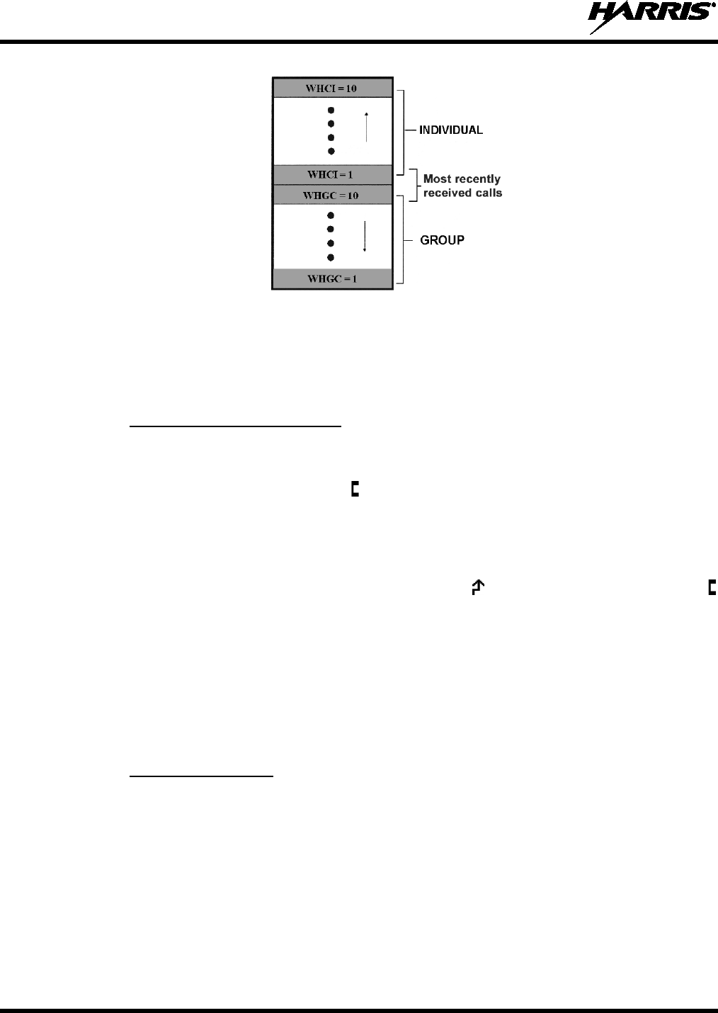
14221-1510-2000, Rev. A
42
Calls Received List
If the INDV function is programmed on a radio menu or to a radio button, access the list by selecting this
function on the menu or by pressing the programmed button twice. Next, press the + or – buttons to scroll
through the list. At this point pressing the microphone’s PTT button will initiate a call to the currently
selected individual caller. Alternately, press the MENU button to display the time elapsed since the call
was received from the currently selected individual caller.
8.4.2 Sending an Individual Call
The following procedures describe how to initiate and send/transmit an individual call.
1. To select a previously stored individual radio unit, select INDV from the menu or press the button
programmed with the INDV function. The (Special Call) icon appears at the bottom of the display.
Next, use the + and – buttons to scroll through the list of stored individual radio units. While in the
individual call list, the MENU button can be pressed to toggle the display between the radio unit’s
name and its ID number.
2. With the desired radio unit selected, press the microphone’s PTT button. The radio performs the
necessary signaling to obtain a communication channel, the (Transmit) icon turns on, and the
(Special Call) icon turns off. When the signaling is complete and the radio is clear to transmit, the
Transmit/Busy indicator lights red and the channel access tone sounds. The display indicates the
called radio unit’s name if found in the list of stored individuals or ID followed by the logical ID
number of the radio unit being called. INDV also displays.
3. Hold the microphone approximately 2 inches from the mouth and speak into the microphone at a
normal voice level. Never shout or whisper into the microphone.
4. Release the PTT button when the transmission is complete, and listen for a reply.
8.4.3 Call Storage Lists
There are two lists available for call storage in the radio: The Calls Received List (1 through 10 as
previously described) and the Personality List (1 through 99 as defined by the user). When the individual
call mode is entered via the INDV function (i.e., by selecting this programmed menu function or by
pressing the programmed INDV button twice), the Calls Received List is available. Toggle to the
Personality List by pressing any other button or by pressing the programmed INDV button again. If wrap
is enabled, the Calls Received List wraps on itself and not into the other list.
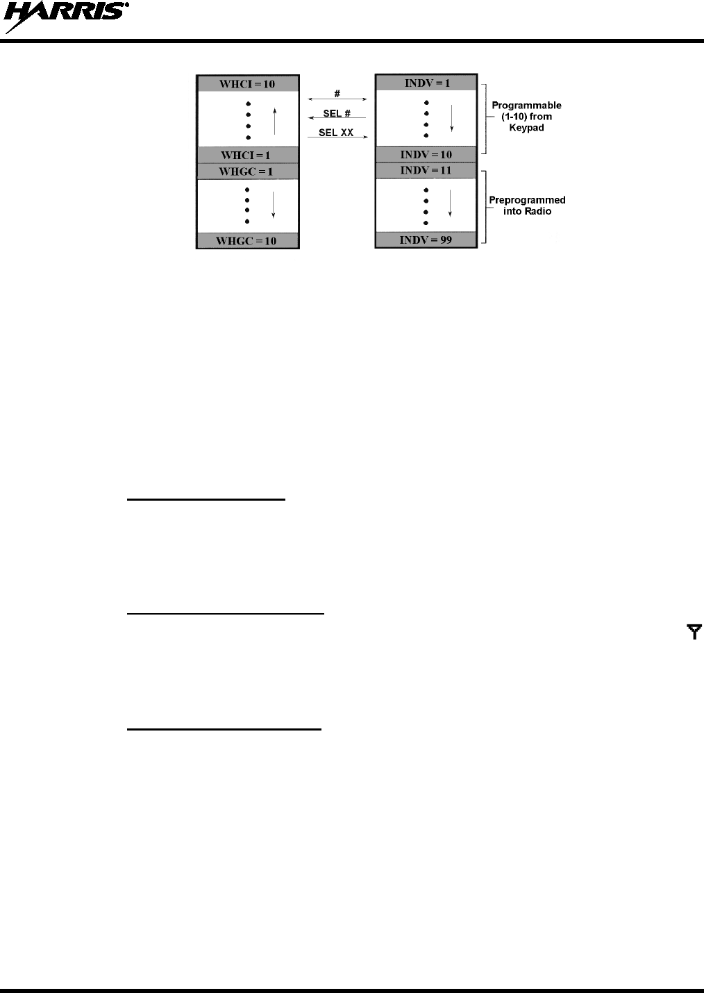
14221-1510-2000, Rev. A
43
Calls Received List Personality List
The Calls Received List shows all ten (10) storage locations. If no calls have been received since the radio
was powered up, this list will be empty. In any case, the Personality List is available upon entering the
individual call mode via the INDV function.
When in the Calls Received List, pressing the MENU button toggles the time stamp display on and off.
The time stamp display indicates how long ago the call was received. It indicates this information as
HH:MM:SS where HH = hours, MM = minutes, and SS = seconds.
When in the Personality List, pressing the MENU button toggles the Logical IDentification (LID) display
on and off. This is the ID numbers of the radios.
8.5 EMERGENCY OPERATIONS ON A TRUNKED SYSTEM
8.5.1 General Information
The radio’s ability to declare an emergency, clear an emergency, remain locked on an emergency and
group, emergency audio operation, and display freeze can each be configured via radio programming. If
the radio is scanning when an emergency is declared, scanning stops and it only restarts after the
emergency is cleared.
8.5.2 Receiving an Emergency
When receiving an emergency call from the selected system and group, an alert beep sounds, the
(Busy) icon displays, and the Tx/Busy indicator lights green. Also, RXEMER flashes in the display
until the emergency condition is cleared. In this case, follow standard emergency procedures established
for the respective radio system.
8.5.3 Declaring an Emergency
To declare (send/transmit) an emergency call to the selected system and group or to an optionally
programmed emergency group, follow this procedure. It is assumed the Home/Emergency button is
programmed to provide an emergency declaration function, and the radio is programmed with the
emergency declaration capability:
1. Set the radio to receive calls on the desired trunked radio system. Refer to Section 8.3.1 on page 40 as
necessary.
2. If the radio is programmed to transmit an emergency on the selected group, select the desired group to
transmit the emergency on. Refer to Section 7.7 on page 29 as necessary.
3. Press and hold the red Home/Emergency button. The required minimum button hold time is
programmable between 0 and 127 seconds; consult with the radio system’s network administration

14221-1510-2000, Rev. A
44
personnel for the specific hold time. Afterwards, the radio transmits an emergency call request with
the radio’s ID number until an emergency working channel assignment is received.
4. When the emergency working channel assignment is received, the radio sounds a single beep (auto-
key alert tone) indicating it is ready for voice transmission. TXEMER flashes in the display until
the emergency is cleared.
5. Press PTT and speak into the microphone in a normal voice. When the radio is transmitting, the
(Transmit) icon appears at the bottom of the display and the Tx/Busy indicator lights red.
6. Release PTT when the transmission is complete and listen for a reply.
8.5.4 Clearing an Emergency
If the radio is programmed with emergency clear capability, an emergency can be cleared as follows:
Press and hold the CLEAR button, then press the red Home/Emergency button, then finally release both
buttons.
8.6 SYSTEM SCAN OPERATIONS ON A TRUNKED SYSTEM
8.6.1 General Information
The radio can be programmed with several different radio system scan related features as described in the
following subsections. These features are automatically enabled upon radio power up. A button or menu
option may also be defined to allow these features, as programmed, to be toggled on and off. The system
scan state is maintained through system changes performed by the radio operator, but it defaults to the on
state at radio power-up.
8.6.2 Wide Area System Scan
The radio can be programmed for Wide Area System Scan operation for roaming across trunked radio
systems. Trunked radio systems manage the radios assigned to the system via control channels throughout
the radio systems. Upon the loss of the currently selected system’s control channel, the radio can be
programmed to automatically scan the control channels of other systems. During this scan condition,
WA SCAN displays. If a new control channel is found, the radio switches to the new system and sounds
an alert tone.
If the radio cannot find the control channel of the selected system and begins Wide Area System Scan
(WA Scan), the radio only scans for the priority system control channel if the priority system is in the WA
Scan list.
8.6.3 ProScan
The radio can be programmed for ProScan™ system scan operation for multi-site applications. When the
currently selected system’s signal quality drops below a predefined level, ProScan provides the radio with
the ability to select a new system for the radio to communicate on. This is accomplished by enabling each
radio to analyze the signal quality of its current control channel and compare it with the signal quality of
the control channel for each site in its adjacency scan list. The signal quality metric used for the ProScan
algorithm is based on a combination of both Received Signal Strength Indicator (RSSI) and Control
Channel Verification (CCV) measurements. When the selected system’s signal quality level degrades
below a programmed level, the radio begins to look for a better control channel. Once a control channel
that exceeds the programmed parameters is found, the radio changes to the new system and emits a tone.
If the control channel is completely lost, the radio enters Wide Area System Scanning and searches the
programmed adjacent systems until a suitable control channel is found.

14221-1510-2000, Rev. A
45
The radio monitors the priority system and switches to the priority system if the priority system meets the
criteria. If ProScan is enabled, the rate at which the radio scans for the priority system is defined by the
System Sample Time control.
8.6.4 Priority System Scan
The radio can also be programmed for Priority System Scan. To ensure this feature operates correctly, the
control channel of the priority system must be located on channel one unless the ProScan algorithm is
being used.
The priority system is the desired or preferred system. While receiving the control channel of the selected
system, the radio periodically leaves the selected system and searches for the control channel of the
priority system at a programmable rate. The programmable rate is defined by the value in the Priority
Scan Time control, unless the ProScan algorithm is enabled. This priority scan timer is reset each time the
PTT button is pressed or when a call is received. If the priority system control channel is found, or meets
the predefined ProScan criteria, the radio automatically switches to the priority system.
8.6.5 Turning System Scan On and Off
8.6.5.1 With the Menu (if programmed)
If the System Scan function is programmed to a radio menu, press the MENU button and then press the +
or – buttons to scroll through the menu until SYS SCAN displays. Next, press the MENU button again to
toggle the System Scan state between on and off. SYSC ON or SYSC OFF displays for two (2) seconds to
show the new system scan state.
8.6.5.2 With a Button (if programmed)
If the System Scan function is programmed to a radio button, press this button to toggle the system scan
feature on and off. SYSC ON or SYSC OFF displays for two (2) seconds to show the new system scan
state.
8.7 GROUP SCAN OPERATIONS ON A TRUNKED SYSTEM
8.7.1 General Information
Talk groups on the radio’s scan list are scanned when the scan feature is turned on (i.e., enabled). Groups
are added to the scan list on a per system basis through programming, the radio keypad, or both,
dependent upon programming. The scan list can be changed by the user from the keypad if the radio is not
programmed with a fixed list. Each system’s group scan list is retained in memory when the radio is
turned off. The radio can also be programmed to provide Trunked Priority Group Scan capability, which
operates similar to priority scan in analog conventional mode. Group scan related features include:
• Scan Hang Time — The delay time the radio waits before resuming scan after the microphone’s
push-to-talk button is released or after the received call has ended (i.e., after the working channel has
dropped).
• TX Select — The group the radio transmits on while scanning. The radio is programmed to transmit
on either the scanned group or the selected group.
• Scan List (privileges) — This feature allows or prohibits scan list changes by the user.
• P1 Programming — Priority group programming is accomplished by one (and only one) of the
following three methods:
14221-1510-2000, Rev. A
46
From the keypad, where the priority programming is not fixed and does not follow the selected
channel;
Priority 1 group programming follows the selected channel; or,
Priority 1 group programming is fixed during PC programming and cannot be changed by the
user.
• P1 Always Scan — Determines if the Priority 1 group is always scanned, regardless of the scan state
set by the user.
8.7.2 Turning Scan On and Off
Toggle scan operation between on (enabled) and off (disabled) by pressing the button programmed with
the SCAN function (typically the SCAN button) or, if programmed, by selecting this function on the
menu. When scan is scanning groups, (i.e., when scan is on/enabled), the (Scan) icon rotates in the
bottom of the display and the radio scans the groups on the trunked group scan list.
Scanning stops when the radio is receiving or transmitting a call. Scanning also stops
while the microphone is off-hook,
if the hookswitch feature is enabled through
programming.
If the radio is not programmed to scan, SCAN DIS (for scan disabled) displays when the
SCAN function is selected.
When a group on the scan list receives a channel assignment, the radio unmutes on the assigned channel,
the Transmit/Busy indicator lights green and the received scan group is displayed.
The radio continues scanning if a new group is selected when scan is on. If the radio is receiving a call on
a non-selected group when scan is turned off, it returns to the selected group.
Pressing the microphone’s PTT button when scan is on causes the radio to transmit either on the
displayed group or on the currently selected group, depending on programming.
When the radio is scanning, selecting the SCAN ADD function (if programmed) recalls the scanned
group that last received a call. This group is recalled for a period equal to the scan hang-time.
8.7.3 Priority Group Scanning
When scan is on (enabled) and the scan list has Priority 1 and Priority 2 groups, the radio listens to calls
on those groups and the selected group. While receiving a scanned group call, the radio continues to
monitor the selected Priority 1 and Priority 2 groups and drops the call if the selected group or other
higher priority call becomes active. During a Priority 2 call the radio continues to monitor for a Priority 1
group call.
The radio monitors for Agency and Fleet calls that correspond to the Agency and Fleet associated with
the Priority 1 and Priority 2 groups. Priority Agency and Fleet calls are indicated by displaying AGENCY
or FLEET and associated Priority 1 or 2 group.
NOTE
NOTE
14221-1510-2000, Rev. A
47
8.7.4 Adding Groups to the Scan List and Changing a Group’s Scan Priority
Either the SCAN ADD function or the SCAN A/D (add/delete) function can be used to add a group to the
scan list and change its scan priority level. This procedure assumes the desired group for adding to the
scan list is programmed in the currently selected system but not currently on the scan list. Also, it is
assumed the radio is not programmed with a fixed scan list.
1. Turn scan off, if it is not already off. This can be accomplished by pressing the button programmed
with the SCAN function (typically the SCAN button) or, if programmed, by selecting this function
on the menu. When scan is off, the icon is not displayed.
2. Select the SCAN ADD function or the SCAN A/D function to add the currently selected group to the
scan list as a non-priority scan group. Either function may be programmed to a radio button or on the
menu. When set as a non-priority scan group, the icon (non-priority scan icon = 3 bars) appears at
the bottom of the display.
If neither function is programmed, it is not possible to add the group to the scan list unless the radio is
re-programmed.
If the radio displays FIXED LST, it is programmed with a fixed scan list and this list
cannot be changed without radio re-programming.
3. If desired, select the same function again to set the group as the Priority 2 scan group. The icon
(Priority 2 scan icon = 2 bars) appears at the bottom of the display.
4. If desired, select the same function again to set the group as the Priority 1 scan group. The icon
(Priority 1 scan icon = 1 bar) appears at the bottom of the display.
If the radio displays FIXED P1, a group has been programmed as the fixed Priority 1
group. In this case, another group cannot be set as the Priority 1 group, and the fixed
Priority 1 group cannot be changed from the Priority 1 group unless the radio is re-
programmed.
5. Another group can be added to the list by selecting the group and then repeating from step 2.
6. If desired, turn scan on by selecting the SCAN function.
If the Priority 1 and Priority 2 groups were already set and a new group is assigned as the Priority 1 or the
Priority 2 scan group, then the previously assigned group changes to non-priority scanning.
When using the SCAN ADD function, the priority level selection sequence advances the group to the
next higher priority level and stops at Priority 1. To select a lower priority level, the group must be
deleted from the scan list (using the SCAN DEL function or the SCAN A/D function) and then added
back to the scan list. Each new group added to the scan list starts at the non-priority level (i.e., the lowest
level).
When using the SCAN A/D function, the priority level selection sequence wraps from Priority 1 to no
scan. Since this function can both add and delete, it may be desired so other functions can be programmed
to the limited number of radio buttons.
8.7.5 Deleting Groups from the Scan List
Either the SCAN DEL (scan delete) function or the SCAN A/D (scan add/delete) function can be used to
delete a group from the scan list. The SCAN A/D function can also be used to change the group’s scan
priority level. This procedure assumes the desired group for deleting from the scan list is programmed in
NOTE
NOTE

14221-1510-2000, Rev. A
48
the currently selected system and currently on the scan list. Also, it is assumed the radio is not
programmed with a fixed scan list.
1. Turn scan off, if it is not already off. This can be accomplished by pressing the button programmed
with the SCAN function (typically the SCAN button) or, if programmed, by selecting this function
on the menu. When scan is off, the icon is not displayed.
2. If programmed, select the SCAN DEL function once to delete/remove the group from the scan list.
The scan icon clears from the display when this function is selected.
Alternately, select the SCAN A/D function one or more times until no scan icons (i.e., no bars)
appear in the display. At this point, the group is removed from the scan list.
If neither function is programmed, it is not possible to delete the group from the scan list unless the
radio is re-programmed.
3. If desired, turn scan on by selecting the SCAN function.
8.7.6 Nuisance Delete
If not the currently selected group, a group can be temporarily deleted from the scan list by selecting the
SCAN DEL (scan delete) function when the radio is scanning and receiving a call on the unwanted
group. This action prevents calls from being received on the unselected group, since the group is
temporarily removed from the scan list. Deletions performed in this manner do not remain deleted after
the radio is turned off and back on.
8.8 TELEPHONE INTERCONNECT CALL OPERATIONS ON A P25
TRUNKED SYSTEM
8.8.1 Receiving a Telephone Interconnect Call
When the radio receives a telephone interconnect call, it unmutes on the assigned working channel, and
displays PHONE, INDV and the (Busy) icon. A telephone interconnect call is handled similar
to an individual call in the trunked system; it is only directed to an individual radio in the system.
To respond to the caller and proceed with the call, press the microphone’s PTT button and speak into the
mic at a normal voice level. When done speaking, release the PTT button and listen for a reply. Repeat as
necessary to complete the conversation.
See the DTMF Overdial section that follows if access to services requiring “overdial” is needed.
Overdial operations are available for any special call whether it is an individual call or a telephone
interconnect call.
8.8.2 Sending a Telephone Interconnect Call
Use the following procedure to initiate and complete a telephone interconnect call:
1. To select the desired programmed telephone number, select the PHONE function (programmed menu
or button) then use the + or – buttons to scroll through the list until the desired number is displayed.
2. Press and release the PTT button. The radio performs the necessary signaling required to obtain a
communication channel for the call. When the signaling is complete and the radio is clear to transmit,
its Transmit/Busy indicator lights red and the channel access tone sounds. The display shows
*PHONE* and indicates the accompanying name. The radio then automatically transmits the number.

14221-1510-2000, Rev. A
49
Unsuccessful interconnect signaling returns the radio to the normal receive mode and the number
remains displayed until the special call is cleared by pressing the CLEAR button or the time-out
expires or another group or system is selected.
3. Telephone ringing is heard. When someone answers the phone, press the microphone’s PTT button
and speak into the mic at a normal voice level. Release the PTT button to listen to the caller.
4. To terminate the call, momentarily press the CLEAR button.
The radio is only capable of half-duplex conversations. The caller’s message can only
be sent if the PTT button is pressed (the radio is transmitting) and the caller can only be
heard when the PTT is released (the radio is receiving).
8.8.3 DTMF Overdial of Programmed Numbers
Once the radio has established a connection to the public telephone system, it may be necessary to
“overdial” more digits to access banking services, answering machines, credit card calls or other types of
systems that require DTMF (Dual-Tone Multi-Frequency) access digits. Overdial operation can also be
used to initiate a telephone interconnect call via DTMF signaling if a dial tone has already been accessed
on the system. Telephone numbers and other number sequences needed during overdial operations can be
programmed into the radio’s phone list.
1. Follow the Sending a Telephone Interconnect Call procedure to establish a connection to the
telephone system, or consult the radio system administrator for the procedure necessary to access a
dial tone on the trunked radio system.
2. To select the desired programmed number, select the PHONE function (programmed menu or
button) then use the + or – buttons to scroll through the list and select the desired number.
3. Press the microphone’s PTT button to send/transmit the selected number.
If a number needs to be transmitted again during the call, it must be selected again via the PHONE
function and the PTT button must be pressed again. This requirement prevents unwanted numbers from
being transmitted the next time(s) the PTT button is pressed during the call.
The overdial selection mode remains active until the call is dropped, cleared, or the radio’s MENU button
is pressed. The overdial selection mode can be re-entered if the call is still active by pressing the MENU
button.
8.9 MOBILE DATA ON A TRUNKED SYSTEM
8.9.1 General Information
During trunked mode operations, voice or data calls can be transmitted or received by the radio. However,
the radio can handle only one type of call at a time. Selection of either data or voice is selected
transparently by the operator through normal usage of the radio.
The radio can be connected to a Mobile Data Terminal (MDT) or to a host computer. Any RS-232
compatible device that supports the Radio Data Interface (RDI) protocol (Version 1.91 or greater) can be
connected to the radio. Support for a MDT or host computer is a programmable option. Additionally, a
radio programmed for a host computer can also be programmed for data-only operation (i.e., no voice
calls can be transmitted or received).
NOTE

14221-1510-2000, Rev. A
50
Always turn the radio off before connecting or disconnecting any cables, including the
data cable. Also, turn power to the radio off when docking or undocking a connected
laptop computer. Failure to turn the power off can damage the radio, requiring service
by a Harris approved service center.
8.9.2 Displays
The following messages may be displayed during the various states of data mode of operation:
TX DATA — Displayed when the radio is transmitting a data call.
RX DATA — Displayed when the radio is receiving a data call.
DATA OFF — Displayed when the radio is in the data disabled state.
DATA ON — Displayed for two seconds when the radio is toggled to the data enabled state.
8.9.3 Data Off Operation
The radio can be placed in the data disabled state by any of the following methods. When the data state is
disabled, the DATA OFF displays. An ongoing data call is allowed to complete except when an
emergency is declared.
• Removing the microphone from the hookswitch (hookswitch option must be enabled by
programming).
• Declaring an emergency (not to be used unless an actual emergency condition exists). Alert tone
sounds.
• Pressing the OPTION button. Alert tone sounds.
• Selecting the programmed function via the MENU button.
8.9.4 Data On Operation
The data state is enabled by one of the following (depending on how it was disabled). DATA ON displays
for two (2) seconds then the display returns to normal.
• Replacing the microphone into the hookswitch (going on-hook). Only valid if the DATA OFF
operation was entered by removing the microphone from the hookswitch (going off-hook).
• Clearing an emergency, but valid only if an emergency caused DATA OFF operation.
8.9.5 Exiting Data Calls
Under normal conditions, the radio enters the scan lockout mode and returns to the control channel after
completion of a data call (transmit or receive). If, during a data call, one of the following conditions
occurs, the data call is immediately terminated and the radio performs the desired function:
• The PTT is activated.
• An emergency is declared by pressing the programmed Emergency/Home button.
• A group or system change is made.
CAUTION

14221-1510-2000, Rev. A
51
8.9.6 Scan Lockout Mode
Following the transmission or reception of a data call, if scan is enabled, scanning stops temporarily
(duration programmed). During this time the scan status icon stops rotating to indicate that scan is
enabled but temporarily suspended. This mode is normally exited when the programmed time expires;
however, the following actions terminate the scan lockout mode before the timeout is completed.
• Pressing the CLEAR button.
• Pressing the microphone’s PTT button.
• Removing the microphone from its hookswitch (i.e., going “off-hook”).
• Changing the currently selected group or system.
• Entering phone call mode.
• Entering individual call mode.
• Receiving a new emergency assignment.
• Declaring or clearing an emergency.
• Receiving an individual or phone call.
• Receiving an Agency, Fleet, or System All Call.
• Pressing the SCAN button (or selecting the SCAN function) to turn scan on or off.
8.9.7 Data Lockout Mode
The data lockout mode is a programmed mode when the radio does not respond to any data channel
assignments and prevents receive data calls from interrupting voice calls. Transmit data calls are still
initiated when needed by the operator. After a programmed time, the radio responds to receive data calls;
however, the following conditions clear the data lockout mode:
• Pressing the CLEAR button.
• Transmitting a data call.
• Changing the system.
• Declaring an emergency.
• Pressing the SCAN button (or selecting the SCAN function) to turn scan on or off.
8.10 STATUS OPERATIONS ON A TRUNKED SYSTEM
The Status feature allows for the transmission of programmed statuses to the radio system. Different
statuses can be programmed into the radio and selected one-at-a-time for transmission. Each status is
assigned an ID number that is cross-referenced with the representative status condition established by
radio system administration personnel. For example, a particular status ID number could be assign as
meaning “Off Duty” throughout the radio system. Note that the same ID number could be programmed,
for example, as “STATUS 1” in one radio but as “STATUS 5” in another radio. At dispatch consoles in
the radio system, the Status feature is typically referred to as Request Status Message (RSM).
One or more radio buttons may be programmed for status operation. For examples, the A button could be
programmed to transmit an “In Route” status after it is pressed, the B button could be programmed to
transmit an “At Scene” status after it is pressed, and the C button could be programmed to transmit a
“Send EMT” status after it is pressed.
14221-1510-2000, Rev. A
52
To transmit a status, press the respective button to set the status for transmission. After a short delay or
after being polled by the radio system (per radio programming), the status will be transmitted. Consult
with radio system’s network administration personnel for programming information for a specific radio.
Transmission of the status set for transmission can be canceled before the timer expires
(or before the radio system polls the radio for it, if so programmed) by pressing the
CLEAR button. This may be necessary if an incorrect status was selected.
If the radio is programmed for automatic status transmission, it transmits the selected status each time the
status is set for transmission (and if used, after the timer expires). However, if the radio is programmed
for polled status transmission, the radio waits until it is polled by the radio system (i.e., the trunked site)
before it transmits the selected status set for transmission.
If the status cannot be transmitted immediately, it is stored in the radio’s memory where it can be polled
by the radio system at a future time.
When the radio system receives a transmitted status, it sends an acknowledgement message back to the
radio and the radio then sounds a high-pitched tone. If the radio system does not receive the status
properly, the radio sounds a low-pitched tone upon receipt of the acknowledgement message from the
radio system.
If no status has been programmed for the selected status, the NO ENTRY displays and the radio sounds a
low-pitched tone.
8.11 MESSAGE OPERATIONS ON A TRUNKED SYSTEM
The Message feature allows for the transmission of programmed messages to the radio system. Different
messages can be programmed into the radio and selected one-at-a-time for transmission. Each message is
assigned an ID number that is cross-referenced with the representative message condition established by
radio system administration personnel. For example, a particular message ID number could be assign as
meaning “Please Call” throughout the radio system. Note that the same ID number could be programmed,
for example, as “MESSAGE 1” in one radio but as “MESSAGE 5” in another radio. At dispatch consoles
in the radio system, the Message feature is typically referred to as Request-To-Talk (RTT), since it allows
a dispatcher to quickly set-up an individual call back to the radio that transmitted a message.
One or more radio buttons may be programmed for message operation. For examples, the A button could
be programmed to transmit a message corresponding to “I-Call ASAP” after it is pressed, and the B
button could be programmed to transmit a message corresponding to “Run Plate” after it is pressed.
To transmit a message, press the respective button to set the message for transmission. After a short delay
or after being polled by the radio system (per radio programming), the message will be transmitted.
Consult with radio system’s network administration personnel for programming information for a specific
radio.
Transmission of the message set for transmission can be canceled before the timer
expires (or before the radio system polls the radio for it, if so programmed) by pressing
the CLEAR button. This may be necessary if an incorrect message was selected.
If the radio is programmed for automatic message transmission, it transmits the selected message each
time the message is set for transmission (and if used, after the timer expires). However, if the radio is
programmed for polled message transmission, the radio waits until it is polled by the radio system (i.e.,
the trunked site) before it transmits the selected message set for transmission.
NOTE
NOTE
14221-1510-2000, Rev. A
53
If the message cannot be transmitted immediately, it is stored in the radio’s memory where it can be
polled by the radio system at a future time.
When the radio system receives a transmitted message, it sends an acknowledgement message back to the
radio and the radio then sounds a high-pitched tone. If the radio system does not receive the message
properly, the radio sounds a low-pitched tone upon receipt of the acknowledgement message from the
radio system.
If no message has been programmed for the selected message, the NO ENTRY displays and the radio
sounds a low-pitched tone.
8.12 DIGITAL VOICE AND ENCRYPTED DIGITAL VOICE OPERATIONS
The XG-25M mobile radio can support various voice modes as described in the following subsections.
8.12.1 Clear Mode
Clear mode can be used in most radio systems. In clear mode, the radio transmits and receives only clear
voice calls. Groups or channels programmed for clear operation cannot transmit or receive digital
(unencrypted) or private (encrypted) calls.
Clear mode transmissions can easily be monitored by unauthorized persons.
8.12.2 Private Mode
Private mode can be employed in any radio system that can support encrypted voice operations.
Encryption protects against unauthorized reception of radio communications. When the radio is in private
mode, the (encryption) icon appears at the bottom of the display.
The XG-25M mobile radio supports both the Advanced Encryption Standard (AES) and the Data
Encryption Standard. DES encryption uses 56-bit keys, while AES uses 128, 192, or 256-bit keys. Since
every additional bit doubles the number of keys that must be attempted for decoding, this makes AES
significantly more robust than DES.
Private mode sets the radio to transmit encrypted calls and to receive both clear and encrypted calls. The
radio transmits private if the group/channel is programmed for private operation and forced operation is
programmed.
If the radio is programmed for auto-select, the radio transmits as follows:
• If private mode is enabled, transmissions are always in private mode.
• If private mode is disabled and a private call is received, the reply transmission is in private mode if
the transmission is made during the scan hang-time. If the reply transmission occurs after the scan
hang-time, the transmission is in clear mode.
When operating on a group or channel programmed for private mode, all transmissions are private and the
radio receives clear and private calls. If the selected group or channel is programmed for auto-select
capability, the mode can be toggled between private and clear by selecting the PVT function
(programmed menu or button). Radios programmed for forced private operation do not allow a change of
the transmit mode; therefore, this button has no effect.
CAUTION
14221-1510-2000, Rev. A
54
8.12.2.1 Displaying the Number of the Currently Used Encryption Key
The number of the encryption key currently in use can be displayed. This is either the number of the
system encryption key (for special calls such as individual, phone, all, agency or fleet) or the number of
the group/channel key (for group or conventional calls). Each number is a storage location number in the
radio for the key, not the actual encryption key.
1. Press the MENU button to activate the menu function. The programmed menu functions appear in the
display. The > symbol at the left of a menu function indicates the currently selected function.
2. Press the + or – buttons to scroll and select the DSP KEY function.
3. Press the MENU button again.
4. Press the + or – buttons to toggle between displaying the number of the system key or the number of
the group/channel key.
Table 8-4: Display Number of Current Encryption Key
ENCRYPTION KEY
DISPLAYED MESSAGE DISPLAYED
System SYS KEY
KEY = 1
Group/Channel GRP KEY or CHN KEY
KEY = 2 or KEY = 2
8.12.2.2 Key Zero
All encryption keys can be cleared (i.e, erased from the radio’s memory) by depressing the CLEAR
button and, with it held down, pressing the OPTION button. Hold both buttons depressed for
approximately two (2) seconds. A series of warning beeps begins at the start of this two-second period
and then it switches to a solid tone after the keys have been cleared. When the encryption keys are
cleared, KEY ZERO displays.
If the encryption key(s) are cleared, one or more keys must be transferred from the Key Loader into the
radio before private communications can continue. Contact the network administration personnel for
further information.
8.12.2.3 Receiving a Private (Encrypted) Call
When receiving, the radio automatically switches between clear or private operation. If the transmission
being received is an encrypted transmission, it is decrypted, the receiver unsquelches, and the call is heard
in the speaker/headset. The selected group or channel must be programmed for private operation and the
correct encryption key must be loaded into the radio for this to occur.
8.12.2.4 Transmitting a Private (Encrypted) Call
1. Select the desired group or channel.
2. If the (encryption) icon is not present at the bottom of the display, place the radio in private mode
by selecting the PVT function. This may be programmed to a menu or button.
• If the last state of the radio was private mode, then private mode is enabled on power up. In
addition, the private mode is enabled if forced operation has been programmed in the radio.

14221-1510-2000, Rev. A
55
• If a group or channel is not programmed for private mode operation, PVT DIS displays if an
attempt is made to enable private transmit mode. In this case, it is not possible to operate on this
group/channel in private mode.
• If the radio is programmed for forced private transmit operation, FRCD PVT displays if an
attempt is made to disable private transmit mode. In this case, it is not possible to transmit on this
group/channel in clear mode.
• If the radio does not have the correct encryption key loaded, NO KEY # displays. In this case, the
radio does not transmit.
3. Continue with standard transmission procedures. A private mode access tone is heard when the
microphone’s PTT button is pressed.
8.12.2.5 Scanned Group Calls
Receiving a scanned group call is the same as receiving a selected group call. During the scan hang time,
if the radio was programmed for auto-select, it transmits back in the same mode it received the call. For
example, if a clear group is entered in the scan list, it only receives clear calls. If the same group was
available in private and entered in the scan list, it can receive clear and private calls, provided auto-select
was programmed in the radio. The user can select to transmit on the scanned or on the selected group. If a
group is entered in the scan list more than once in different modes (clear, digital, private), only the first
occurrence of the group is used.
8.12.3 Error Messages
If any of the following error messages are displayed, the radio was either programmed incorrectly or
requires service:
DSP ERR
ERR=xxxx
DSP ERR
DIGV ERR
If the radio’s hardware circuit is not responding correctly at radio power-up, the following error message
is displayed. In this case, the radio requires service:
HARDWARE
ERR = 3X
(Where 3X is a number between 30 and 38).
8.13 DYNAMIC REGROUP OPERATION
8.13.1 General Information
Dynamic regroup operation is a feature that permits up to eight (8) talk groups to be added to a radio by
network administration personnel. The radio must be programmed to respond to regrouping. Dynamic
regrouping is not activated in a radio until an activation message is sent from the radio system. Each radio
that receives and acknowledges regrouping instructions is successfully regrouped.
Pressing and holding the CLEAR button for 2.5 seconds toggles the radio into and out of the dynamic
regroup group set. A double beep sounds for entry or exit. The radio displays REGR_0x where x is a digit
of 1 to 8 indicating the group when dynamic regroup has been enabled by the user. If the radio is in
dynamic regroup and the user selects a group that has not been regrouped, NO ENTRY displays. The radio
is prevented from transmitting and receiving calls in this condition except for scanned groups.

14221-1510-2000, Rev. A
56
8.13.2 Emergency Operation
If the programmed group set on the currently selected system contains an emergency/home group and the
radio is in dynamic regroup, the radio exits dynamic regroup and declares the emergency on the home
group. If no emergency/home group is present, the radio declares the emergency on the currently selected
dynamic regroup group.
8.14 PAGING OPERATIONS (P25 TRUNKED SYSTEMS ONLY)
The radio’s paging feature, if programmed, sends a “ping” type message to another radio in a P25 trunked
system. It functions similar to the individual call feature. To initiate and complete a page:
1. Press the MENU button to activate the menu function. The programmed menu functions appear in the
display. The > symbol at the left of a menu function indicates the currently selected function.
Alternately, if another button such as one (1) of the three (3) preset buttons is programmed with the
Page function, press this button and advance to step 4.
2. Press the + or – buttons to scroll through the menu until PAGE is selected.
3. Press the MENU button again to access the individual call list.
4. Press the + or – buttons to select a previously stored radio via the individual call list. While in the
individual call list, press the MENU button to toggle the display between the calling radio’s call name
(i.e., alias) and the calling radio’s unit ID number (i.e., logical ID number).
5. Press the microphone’s PTT button. The radio performs the necessary signaling on the control
channel. On the calling radio, the called individual’s name if found in the individuals call list, or ID
followed by the radio unit ID number of the radio being called displays. If the receiving radio
receives the page and responds, both radios emit three (3) high-pitched tones. The receiving radio also
displays PAGE and the calling radio’s identification.

14221-1510-2000, Rev. A
57
9 P25 CONVENTIONAL OPERATIONS
The following subsections describe operations when a P25 conventional radio system is selected.
9.1 MESSAGES DISPLAYED DURING P25 CONVENTIONAL
OPERATIONS
During P25 conventional operations, various messages may appear in the display, as listed and described
in the following table:
Table 9-1: Messages Displayed during P25 Conventional Operations
MESSAGE NAME DESCRIPTION
TALKARND Talk-Around
The radio is operating in talk-
around mode. In this mode, the radio’s
transmit and receive frequencies are the same for the
currently
selected channel. Appears in the top line of the display when the
radio is in this mode; otherwise, the selected system’s name appears
there.
SYS ALL System All Call A system all-call has been received.
RXEMER
Emergency
Received An emergency call is being received by the radio. See Section 9.5.1
on page 62.
TXEMER
Emergency
Transmitted An emergency call has been transmitted
(i.e., declared) from the
radio. See Section 9.5.2 on page 62.
EM x Emergency
Declared An emergency has been declared by the
radio ID number that
follows in the display. EM 01201 for example.
UNKNOWN Caller's ID Not
Received A
n individual call is being received, but the caller's ID was not
received. See Section 9.4.1 on page 61.
VOL = xx Volume Level The current volume level. The volume level ranges from OFF
(muted) to 40 (loudest). See Section 6.1 on page 24.
VOLUME: OFF Volume Muted Receiver audio in the speaker/headset is completely muted.
ALRM ON External Alarm
Enabled The external alarm function of the radio is enabled.
ALRM OFF External Alarm
Disabled The external alarm function of the radio is disabled.
BCKL x Backlight Level Display intensity and keypad backlight level. See Section 7.4.
CNTRST= x Contrast Level Display contrast level. See Section 7.5.
GR Group ID The incoming call is a group call
. GR is followed by the group ID
number of the group, GR 101 for example.
ID Individual ID The incoming call is an individual call
. ID is followed by the
individual/unit ID number of the calling radio, ID 2725 for example.

14221-1510-2000, Rev. A
58
Table 9-1: Messages Displayed during P25 Conventional Operations
MESSAGE NAME DESCRIPTION
WHC = x Who Has Called
The
number from the Who Has Called (WHC) list. Individual calls
received but not responded to are stored in a Who Has Called list.
This list is accessible by selecting the INDV function (programmed
menu or button) after the individual call has timed out or af
ter the
CLEAR button has been pressed after receiving an individual call.
This indication clears if the individual call mode is entered, the radio
system is changed, or the radio is turned off and then on again.
Refer to Section 8.4.3 on page 42 for additional information.
MENU Menu
Selection
Displayed in the top line (line 1) of the display just after pressing the
MENU button to activate the menu function. See Section 7.10
on
page 31.
SYS = x System
Selection The System Selection function is active. See Section 7.6.3
on page
28.
GRP = x Group/Channel
Selection The Group/Channel Selection function is active. See Section 7.7.3
on page 29.
GROUP
Group Call A group call is in progress.
INDV = x Individual Call
List Number Indicates which item in the individual call list is being displayed. The
name or ID of the item in the list is also displayed. Range = 1 to 99.
INDV
Individual Call An individual call is in progress.
SEL INDV Select
Individual ID
A
n entry from the individual ID list is selected after pressing the
programmed individual call list (INDV) button
. The entry is a number
between 1 and 32 inclusive.
PHONE Phone Call A phone call is being received from the radio system/site
. Message
“*INDV*” also appears since the radio handles
a received phone call
as an individual call.
PHN = x Phone Call List
Number Indicates which item in the phone list is being displayed.
Range = 1
to 99.
PHONE
Phone Call An initiated phone call is in progress.
SEL PHN Select Phone
Selecting an entry from the phone list by typing the entry number
displays this message.
INV SYS Invalid System The currently selected radio system is invalid.
This can occur
because the respective feature encryption data does not exists in the
radio, but the radio is programmed with a respective system.
NO ENTRY —
• Indicates there is no data stored
in one of the programmable
items in either the phone list or individual call list. The user
programmable items are items 1 through 10 in each list.
•
During status operations, indicates no status has been
programmed for the selected entry.
FIX LIST Fixed List The priority scan list is fixed via radio programming. This
cannot be
changed except by reprogramming the radio.
FIXED P1 Fixed
Priority 1 The Priority 1 scan group is fixed and it cannot be changed
expect
by reprogramming the radio.

14221-1510-2000, Rev. A
59
Table 9-1: Messages Displayed during P25 Conventional Operations
MESSAGE NAME DESCRIPTION
SPKR ON External
Speaker On The external speaker is enabled.
SPKR OFF External
Speaker Off The external speaker is disabled.
PVT DIS Private Mode
Disabled Private mode is disabled or no encryption key has been programmed
for the selected group or special call.
FRCD PVT Forced Private
Operation Forced private operation has been programmed into radio.
NO KEY # Encryption Key
Missing There is
no encryption key or an incorrect encryption key is
programmed into the radio.
BANK=1-8 Encryption Key
Bank Number
The bank of
encryption keys that are going to be loaded when the
keyloader loads encryption keys. This is only valid for radios that
support encryption. It is displayed when the encryption key keyloader
is connected.
KEY LOAD Encryption
Keyloader
Connected The encryption key keyloader is connected.
KEY ZERO Encryption Keys
Cleared/Zeroed The encryption keys are cleared. See Section 8.12.2.2 on page 54.
SYS KEY Encryption
System Key
From the DISP KEY
(Display Key) menu, this indicates the key
number used by the selected system. It is followed by
key number
“KEY = x” where “x” = 1 through 7.
GRP KEY Encryption
Group Key
From the DISP KEY
(Display Key) menu, this indicates the key
number used by the selected group. It is followed by
key number
“KEY = x” where “x” = 1 through 7.
KEY=x Encryption Key
Number In the DISP KEY
(Display Key) menu, this indicates the currently
selected group/system key, where “x” = 1 through 7.
PRIMARY Encryption Key
Primary The primary encryption keys are enabled.
(c) 2012 Software
Copyright Year Copyright year of the radio’s flash software. In the REVISION
menu,
displayed on line 3 (scrolling may be necessary).
FLSH VER Radio’s Flash
Code Version Radio software version number
. The version number appears on line
3 in the REVISION menu (scrolling may be necessary).
PERSNLTY Personality
Name
Name of the personality currently programmed into the radio. The
name appears on line 3 in the REVISION menu (scrolling may be
necessary).
14221-1510-2000, Rev. A
60
9.2 ALERT TONES DURING P25 CONVENTIONAL OPERATIONS
The radio provides audible alert tones (“beeps”) to indicate the various operating conditions. These alert
tones can be enabled or disabled through programming.
Table 9-2: Alert Tones during P25 Conventional Operations
NAME TONE DESCRIPTION
Call
Originate 1 short mid-
pitched tone Sounds after keying the radio (Push-To-
Talk button is pressed).
Indicates it is OK to begin speaking into the microphone.
Carrier
Control
Timer
5 short high-pitched
warning tones
followed by a long
low-pitched tone
Sounds if the programmed time for continuous transmission is
exceeded.
The transmitter shuts down shortly after the alert,
interrupting communications. Release and re-
key the PTT
button to maintain communications. This resets the carrier
control timer and turns the transmitter back on.
Key
Press
Alert 1 short tone Indicates a key has been pressed. A short low-
pitched tone
indicates no
action was taken because the key is not active in
the current mode.
9.3 GROUP CALLS ON A P25 CONVENTIONAL SYSTEM
9.3.1 Receiving a Group Call
1. If not already, turn the radio on by rotating its Power On/Off/Volume control clockwise out of the
detent position. The radio’s display activates and if enabled through programming, a short alert signal
sounds to indicate the radio is ready to use.
2. Select the desired P25 conventional radio system. Refer to Section 7.6 as necessary. The currently
selected system is indicated in the top line of the display, and the (P25) icon appears at the bottom
of the display.
3. Select the desired group. Refer to Section 7.7 as necessary. The currently selected group is indicated
in the middle line of the display. The radio is now ready to receive calls on the group. It unmutes
according to the squelch mode defined by radio programming (monitor, normal, selective).
4. When the radio receives a group call, it unmutes, GR and the calling radio’s unit ID or the group’s
name displays. Also, the Tx/Busy indicator lights green.
5. If necessary, make a volume adjustment by rotating the Power On/Off/Volume control.
9.3.2 Transmitting a Group Call
1. Set the radio to receive calls on the desired P25 conventional radio system and talk group per the
previous section.
2. When the group is clear (i.e., no call is being received on it), press and hold the PTT button.
3. After the call originate tone sounds (a short mid-pitched beep), begin speaking into the microphone.
When speaking, hold the microphone approximately 1-½ inches from the mouth. Some radios may be
programmed without a call originate tone. If so, pause a short time after depressing the PTT button
before beginning to speak.
4. Release the PTT button when the transmission is complete and listen for a reply.
5. Repeat transmissions as necessary.
14221-1510-2000, Rev. A
61
9.4 INDIVIDUAL CALLS ON A P25 CONVENTIONAL SYSTEM
9.4.1 Receiving and Responding to an Individual Call
An individual call is a unit-to-unit radio call which involves only two (2) radios. When the radio receives
an individual call from another radio, it unmutes (i.e., audio transmitted from the calling radio is heard in
the speaker/headset) and the (Busy) status icon displays. The radio may also be programmed to ring, as
described in the next paragraph. Upon receiving an individual call, the radio displays either the logical ID
number or the name of the radio unit that originated the individual call. If the originating radio unit’s
name is present in the radio (respective to its ID number), the originating radio unit’s name is displayed.
If the originating radio unit’s name is not present in the radio (respective to its ID number), the
originating radio’s ID number is displayed.
The radio can be programmed to ring when an individual call is received. If so, the ring begins five (5)
seconds after the caller (i.e., the originating radio) unkeys and it will continue until the microphone’s PTT
button is pressed, or the CLEAR button is pressed, or the individual call mode is entered. The volume
level of the ring is adjustable via the radio’s Power On/Off/Volume control.
The microphone’s hookswitch functions the same as the CLEAR button in individual
call, phone call, and menu modes.
If a response is made to the call by pressing the microphone’s PTT button prior to expiration of the
programmed call-back time-out period, the call will be automatically directed to the originating unit via
an individual call. If a response is not made before the call-back time-out period expires, the radio will
return to normal receive display, and WHC (Who Has Called) will appear in the display.
To respond after expiration of the call-back time-out period, press the programmed Individual Call
function key (if programmed) or access this function via the menu. The radio’s display will show the
caller’s ID and WHCI=1 (Who Has Called – Individual 1) . At this point, pressing the microphone’s PTT
button will initiate an individual call back to the original caller.
Pressing the CLEAR button cancels reception of an individual call and returns the radio to the normal
operation. In this case, if the name and/or ID number of the originating radio is not known, the Who Has
Called (WHC) list must be accessed in order to call the originating radio back.
Pressing the microphone’s PTT button will initiate an individual call to the displayed logical ID.
Powering the radio off and on will clear this list.
The basic procedure to receive an individual call on a P25 conventional radio system is:
1. If not already, turn the radio on by rotating its Power On/Off/Volume control clockwise out of the
detent position. The radio’s display activates and if enabled through programming, a short alert signal
sounds to indicate the radio is ready to use.
2. Select the desired P25 conventional radio system. Refer to Section 7.6 as necessary. The currently
selected system is indicated in the top line of the display.
3. The radio is now ready to receive group and individual calls. It unmutes according to the squelch
mode defined per radio programming (monitor, normal, selective).
4. When the radio receives an individual call, it unmutes and the unit ID/name of the calling (i.e.,
transmitting) radio displays.
5. Rotate the Power/On/Off/Volume control to adjust the radio to desired volume level.
6. Press the PTT button to respond to the caller.
NOTE
14221-1510-2000, Rev. A
62
Unanswered individual calls appear in the Who Has Called (WHC) list.
9.4.2 Transmitting an Individual Call
1. Press the MENU button to activate the menu function. The programmed menu functions appear in the
display. The > symbol at the left of a menu function indicates the currently selected function.
2. Select the desired radio unit for calling from either the Calls Received List (WHCI1 through
WHCI10) or a pre-stored unit via the Individual Call (INDV) menu function (if programmed).
To select a pre-stored unit (if programmed) from the Individual Call menu, scroll through the list of
pre-stored phone numbers using the + or - buttons until the desired ID number or unit name is
displayed, the press the MENU button.
3. Press the microphone’s PTT button. When the radio is clear to transmit turns on, turns off, and
the channel access tone sounds. The called individual’s name (or radio ID number) and INDV
(Individual) display.
9.5 EMERGENCY GROUP CALLS ON A P25 CONVENTIONAL SYSTEM
When operating on a P25 conventional system, there is no method available for a
system-wide emergency clear. An emergency group call must be manually cleared at
each radio. See Section 9.5.3 that follows for clearing methods that can be used.
9.5.1 Receiving an Emergency Group Call
1. If not already, turn the radio on by rotating its Power On/Off/Volume control clockwise out of the
detent position. The radio’s display activates and if enabled through programming, a short alert signal
sounds to indicate the radio is ready to use. Also depending upon radio programming, the radio
powers-up with either the last selected group or the power-up group.
2. Select the desired/required P25 conventional radio system. Refer to Section 7.6 as necessary. The
currently selected system is indicated in the top line of the display, and the (P25) icon appears at
the bottom of the display.
3. Select the desired group. Refer to Section 7.7 as necessary. The currently selected group is indicated
in the middle line of the display. The radio is now ready to receive calls on the group.
When the radio detects an incoming emergency group call, it sounds an alert tone and RXEMER
displays. Voice or emergency transmissions are heard.
9.5.2 Declaring an Emergency on a Group
1. Set the radio to receive calls on the desired P25 conventional radio system and talk group per the
previous section.
2. Press the red Emergency/Home button on the front of the radio. The radio then broadcasts a short
emergency transmission and TXEMER displays.
3. To send a voice message, press the microphone’s PTT button and speak into the microphone.
9.5.3 Clearing an Emergency
Clear an emergency using one of the following methods:
• Select another radio system;
NOTE
14221-1510-2000, Rev. A
63
• Change channels (if not prohibited by radio programming);
• Cycle radio power by turning the radio off and then back on; or,
• If the radio is programmed with clear emergency privileges, simultaneously press the CLEAR
button and the red Emergency/Home button.
9.6 STATUS OPERATIONS ON A P25 CONVENTIONAL SYSTEM
The Status feature allows for the transmission of programmed statuses to the radio system. Different
statuses can be programmed into the radio and selected one-at-a-time for transmission. Each status is
assigned an ID number that is cross-referenced with the representative status condition established by
radio system administration personnel. For example, a particular status ID number could be assign as
meaning “Off Duty” throughout the radio system. Note that the same ID number could be programmed,
for example, as “STATUS 1” in one radio but as “STATUS 5” in another radio. At dispatch consoles in
the radio system, the Status feature is typically referred to as Request Status Message (RSM).
One or more radio buttons may be programmed for status operation. For examples, the A button could be
programmed to transmit an “In Route” status after it is pressed, the B button could be programmed to
transmit an “At Scene” status after it is pressed, and the C button could be programmed to transmit a
“Send EMT” status after it is pressed.
To transmit a status, press the respective button to set the status for transmission. After a short delay, the
status will be transmitted. Consult with radio system’s network administration personnel for programming
information for a specific radio.
Transmission of the status set for transmission can be canceled before the timer expires
by pressing the CLEAR button. This may be necessary if an incorrect status was
selected.
When the radio system receives a transmitted status, it sends an acknowledgement message back to the
radio and the radio then sounds a high-pitched tone. If the radio system does not receive the status
properly, the radio sounds a low-pitched tone upon receipt of the acknowledgement message from the
radio system.
9.7 MESSAGE OPERATIONS ON A P25 CONVENTIONAL SYSTEM
The Message feature allows for the transmission of programmed messages to the radio system. Different
messages can be programmed into the radio and selected one-at-a-time for transmission. Each message is
assigned an ID number that is cross-referenced with the representative message condition established by
radio system administration personnel. For example, a particular message ID number could be assign as
meaning “Please Call” throughout the radio system. Note that the same ID number could be programmed,
for example, as “MESSAGE 1” in one radio but as “MESSAGE 5” in another radio. At dispatch consoles
in the radio system, the Message feature is typically referred to as Request-To-Talk (RTT), since it allows
a dispatcher to quickly set-up an individual call back to the radio that transmitted a message.
One or more radio buttons may be programmed for message operation. For examples, the A button could
be programmed to transmit a message corresponding to “I-Call ASAP” after it is pressed, and the B
button could be programmed to transmit a message corresponding to “Run Plate” after it is pressed.
To transmit a message, press the respective button to set the message for transmission. After a short delay,
the message will be transmitted. Consult with radio system’s network administration personnel for
programming information for a specific radio.
NOTE

14221-1510-2000, Rev. A
64
Transmission of the message set for transmission can be canceled before the timer
expires by pressing the CLEAR button. This may be necessary if an incorrect message
was selected.
When the radio system receives a transmitted message, it sends an acknowledgement message back to the
radio. The radio sounds a high-pitched tone upon receiving this acknowledgement message. If the radio
system does not receive the message properly, the radio sounds a low-pitched tone upon receipt of the
acknowledgement message from the radio system.
NOTE

14221-1510-2000, Rev. A
65
10 ANALOG CONVENTIONAL OPERATIONS
The following subsections describe operations when an analog conventional radio system is selected.
10.1 MESSAGES DISPLAYED DURING ANALOG CONVENTIONAL
OPERATIONS
During analog conventional operation, various messages may appear in the display, as listed and
described in the following table:
Table 10-1: Messages Displayed during Analog Conventional Operations
MESSAGE NAME DESCRIPTION
TALKARND Talk-Around
The radio is operating in talk-around mode
. In this mode, the radio’s
transmit and receive frequencies are the same for
the currently
selected channel. Appears in the top line of the display
when the
radio is in this mode; otherwise, the selected system’s name appears
there.
VOL = xx Volume Level The current volume level. The volume level ranges from OFF
(muted) to 40 (loudest). See Section 6.1 on page 24.
VOLUME: OFF Volume Muted Receiver audio in the speaker/headset is completely muted.
T99 ON Type 99
Decode On Type 99 decoding is enabled.
T99 OFF Type 99
Decode Off Type 99 decoding is disabled.
ALRM ON External Alarm
Enabled The external alarm function of the radio is enabled.
ALRM OFF External Alarm
Disabled The external alarm function of the radio is disabled.
BCKL x Backlight Level Display intensity and keypad backlight level. See Section 7.4.
CNTRST=x Contrast Level Display contrast level. See Section 7.5.
MENU Menu
Selection
Displayed in the top line (line 1) of the display just after pressing the
MENU button to activate the menu function. See Section 7.10
on
page 31.
SYS = x System
Selection The System Selection function is active. See Section 7.6.3
on page
28.
CHN = x Group/Channel
Selection The Group/Channel Selection function is active. See Section 7.7.3
on page 29.
PHN = x Phone Call List
Number Indicates which item in the phone list is being displayed.
Range = 1
to 99.
*PHONE* Phone Call An initiated phone call is in progress.
SEL PHN Select Phone
Selecting an entry from the phone list by typing the entry number
displays this message.
INV SYS Invalid System The currently selected radio system is invalid.
This can occur
because the respective feature encryption data does not exists in the
radio, but the radio is programmed with a respective system.

14221-1510-2000, Rev. A
66
Table 10-1: Messages Displayed during Analog Conventional Operations
MESSAGE NAME DESCRIPTION
NO ENTRY — There is no data stored in one of the programmable items in either
the phone list or individual call list. The user
programmable items are
items 1 through 10 in each list.
FIX LIST Fixed List The priority scan list is fixed via radio programming. This
cannot be
changed except by reprogramming the radio.
FIXED P1 Fixed
Priority 1 The Priority 1 scan channel is fixed and it cannot be changed
expect
by reprogramming the radio.
SPKR ON External
Speaker On The external speaker is enabled.
SPKR OFF External
Speaker Off The external speaker is disabled.
PVT DIS Private Mode
Disabled Private mode is disabled or no encryption key has been programmed
for the selected channel.
FRCD PVT Forced Private
Operation Forced private operation has been programmed into radio.
NO KEY # Encryption Key
Missing There is no encryption key or an
incorrect encryption key is
programmed into the radio.
BANK=1-8 Encryption Key
Bank Number
The bank of encryption keys that are going to be loaded when the
keyloader loads encryption keys. This is only valid for radios that
support encryption. It is displayed when the encryption key keyloader
is connected.
KEY LOAD Encryption
Keyloader
Connected The encryption key keyloader is connected.
KEY ZERO Encryption Keys
Cleared/Zeroed The encryption keys are cleared. See Section 8.12.2.2 on page 54.
SYS KEY Encryption
System Key
From the DISP KEY
(Display Key) menu, this indicates the key
number used by the selected system. It is followed by
key number
“KEY = x” where “x” = 1 through 7.
KEY=x Encryption Key
Number In the DISP KEY
(Display Key) menu, this indicates the currently
selected channel’s key number, where “x” = 1 through 7.
PRIMARY Encryption Key
Primary The primary encryption keys are enabled.
(c) 2012 Software
Copyright Year Copyright year of the radio’s flash software. In the REVISION
menu,
displayed on line 3 (scrolling may be necessary).
FLSH VER Radio’s Flash
Code Version Radio software version number
. The version number appears on line
3 in the REVISION menu (scrolling may be necessary).
PERSNLTY Personality
Name
Name of the personality currently programmed into the radio. The
name appears on line 3 in the REVISION menu (scrolling may be
necessary).
14221-1510-2000, Rev. A
67
10.2 ALERT TONES DURING ANALOG CONVENTIONAL OPERATIONS
The radio provides audible alert tones (“beeps”) to indicate the various operating conditions. These alert
tones can be enabled or disabled through programming.
Table 10-2: Alert Tones during Analog Conventional Operations
NAME TONE DESCRIPTION
Call
Originate 1 short mid-
pitched tone Sounds after keying the radio (Push-To-
Talk button is pressed).
Indicates it is OK to begin speaking into the microphone.
Carrier
Control
Timer
5 short high-pitched
warning tones
followed by a long
low-pitched tone
Sounds if the programmed time for continuous transmission is
exceeded.
The transmitter shuts down shortly after the alert,
interrupting communications. Release and re-
key the PTT
button
to maintain communications. This resets the carrier
control timer and turns the transmitter back on.
Key
Press
Alert 1 short tone Indicates a key has been pressed. A short low-
pitched tone
indicates no action was taken because the key is not active in
the current mode.
Signaling 1 mid-pitched tone
Sounds just after keying or just after unkeying the radio (i.e.,
just after PTT button press or release). During the tone, the
radio is transmitting data information via signaling, such as
MDC-120 signaling.
10.3 RECEIVING A CALL ON AN ANALOG CONVENTIONAL SYSTEM
Follow this basic procedure to receive a call:
1. If not already, turn the radio on by rotating its Power On/Off/Volume control clockwise out of the
detent position. The radio’s display activates and if enabled through programming, a short alert signal
sounds to indicate the radio is ready to use.
2. Select the desired analog conventional radio system. Refer to Section 7.6 as necessary. The currently
selected system is indicated in the top line of the display, and the (analog channel) icon appears at
the bottom of the display.
3. Select the desired channel. Refer to Section 7.7 as necessary. The currently selected channel is
indicated in the middle line of the display. The radio is now ready to receive calls on the channel.
4. When the radio receives a call (and the correct encoding is decoded, if programmed and enabled), it
unmutes on the channel, the (Busy) status icon displays, and the Tx/Busy indicator lights green to
visually indicate the presence of the call on the channel.
Optional: Press the CLEAR button to disabled squelch and monitor any calls on the channel (with or
without signaling).
5. If necessary, make a volume adjustment by rotating the Power On/Off/Volume control.
10.4 TRANSMITTING A CALL ON AN ANALOG CONVENTIONAL
SYSTEM
Follow this basic procedure to receive a call:
1. Select the desired analog conventional radio system. Refer to Section 7.6 as necessary. The currently
selected system is indicated in the top line of the display.
2. Select the desired channel. Refer to Section 7.7 as necessary. The currently selected channel is
indicated in the middle line of the display. The radio is now ready to receive calls on the channel.
14221-1510-2000, Rev. A
68
3. Verify the channel is not busy (i.e., no call currently exists on it) by observing for the lack of the
(Busy) status icon in the display. If this icon is present in the display, do not proceed until it
disappears.
For an analog convention channel, a channel’s busy/not busy status can also be checked
by briefly depressing the radio’s CLEAR button. This disables squelch and any channel
programmed decoding and unmutes the receiver. Therefore, any signals received on the
channel can be heard in the speaker/headset.
If the Channel Busy Lockout feature is programmed for the selected channel, the radio
will not transmit when the channel is busy
4. Press and hold the microphone’s PTT button. If the Call Originate (sometimes called Ready-To-Talk)
alert tone is programmed, the radio will sound a short beep tone when it begins transmitting on the
channel.
5. Hold the microphone approximately 1-½ inches from the mouth and speak into it in a normal voice.
6. When the transmission is complete, release the PTT button and listen for a reply.
7. Repeat transmissions as necessary.
10.5 SCANNING CHANNELS ON AN ANALOG CONVENTIONAL SYSTEM
Channels which have been previously added to the scan list on a per radio system basis, can be scanned.
The selected channel is scanned (if enabled through programming) whether or not it is in the scan list.
Each conventional radio system’s channel scan list is retained in memory when the radio is turned off.
The scan rate varies depending upon the number of channels in the scan list and whether or not the radio
is programmed to scan for channels with decoding enabled. Fewer channels results in a faster scan rate. If
programmed for dual-priority scan operation, the priority 1, priority 2, and the remaining scan list
channels are scanned. Once a signal is detected and the correct encoded squelch signal is decoded (if
programmed), the radio receives the message and displays the received scan channel. At the same time,
scanning continues on the priority 1 and priority 2 channels. If a priority 1 or priority 2 channel carrier,
regardless of encoded squelch decoding, is detected while a non-priority channel is being received, the
display name is updated and the received channel is switched to the priority channel. Scanning of the
priority 1 channel continues if a message is being received on the priority 2 channel.
While receiving a call on a non-priority or a priority 2 channel, the radio periodically checks the priority 1
and 2 channels. If scan with Channel Guard is enabled, the radio uses Channel Guard to decide whether to
unmute on a priority channel. The radio stops, on squelch detection, on a priority channel. In normal
operation, the radio unmutes only on detecting the correct Channel Guard; otherwise, it remains muted
until the priority channel call and hang time have ended. An optional feature allows the radio to continue
scanning upon the detection of the wrong Channel Guard on a priority channel. The user can then select
the rate at which this channel is scanned until the call ends.
10.5.1 Turning Scan On and Off
Toggle scan operation on and off by selecting the SCAN function. Typically, this is performed by
pressing the SCAN button, if so programmed. This function may also be programmed to the radio’s
conventional menu. When the radio is scanning channels (i.e., when scan is on), the (Scan) icon rotates
in the bottom line of the display and the radio scans the channels currently on the conventional scan list.
NOTE
NOTE
14221-1510-2000, Rev. A
69
Scanning stops when the radio is receiving or transmitting a call. Scanning also stops
while the microphone is off-hook if the hookswitch function is enabled via radio
programming.
When a channel on the scan list has an active call, the radio unmutes, the Tx/Busy indicator lights green,
and the call is heard in the radio’s speaker/headset.
The radio continues scanning if a new channel is selected when scan is on. If the radio is receiving a call
on a non-selected channel when scan is turned off, it returns to the selected channel.
Pressing the PTT button when scan is on causes the radio to transmit on the displayed channel or on the
currently selected channel, depending on programming.
When the radio is scanning, selecting the SCAN ADD function (if programmed) recalls the scanned
channel that last received a call. This channel is recalled for a period equal to the scan hang-time. This
function may be programmed to the radio’s conventional menu or to a radio button.
When scan is turned off, the radio resumes operation on the selected channel.
10.5.2 Adding Channels to the Scan List
Either the SCAN ADD function or the SCAN A/D (add/delete) function can be used to add a channel to
the scan list and change its scan priority level. This procedure assumes the desired channel for adding to
the scan list is programmed in the currently selected system but not currently on the scan list. Also, it is
assumed the radio is not programmed with a fixed scan list.
1. Turn scan off, if it is not already off. This can be accomplished by pressing the button programmed
with the SCAN function (typically the SCAN button) or, if programmed, by selecting this function
on the menu. When scan is off, the icon is not displayed.
2. Select the SCAN ADD function or the SCAN A/D function to add the currently selected channel to
the scan list as a non-priority scan channel. Either function may be programmed to a radio button or
on the menu. When set as a non-priority scan channel, the icon (non-priority scan icon = 3 bars)
appears at the bottom of the display.
If neither function is programmed, it is not possible to add the channel to the scan list unless the radio
is re-programmed.
If the radio displays FIXED LST, it is programmed with a fixed scan list and this list
cannot be changed without radio re-programming.
3. If desired, select the same function again to set the channel as the Priority 2 scan channel. The icon
(Priority 2 scan icon = 2 bars) appears at the bottom of the display.
4. If desired, select the same function again to set the channel as the Priority 1 scan channel. The icon
(Priority 1 scan icon = 1 bar) appears at the bottom of the display.
If the radio displays FIXED P1, a channel has been programmed as the fixed Priority 1
channel. In this case, another channel cannot be set as the Priority 1 channel, and the
fixed Priority 1 channel cannot be changed from the Priority 1 channel unless the radio
is re-programmed.
5. Another channel can be added to the list by selecting the channel and then repeating from step 2.
6. If desired, turn scan on by selecting the SCAN function.
NOTE
NOTE
NOTE

14221-1510-2000, Rev. A
70
If the Priority 1 and Priority 2 channels were already set and a new channel is assigned as the Priority 1 or
the Priority 2 scan channel, then the previously assigned channel changes to non-priority scanning.
When using the SCAN ADD function, the priority level selection sequence advances the channel to the
next higher priority level and stops at Priority 1. To select a lower priority level, the channel must be
deleted from the scan list (using the SCAN DEL function or the SCAN A/D function) and then added
back to the scan list. Each new channel added to the scan list starts at the non-priority level (i.e., the
lowest level).
When using the SCAN A/D function, the priority level selection sequence wraps from Priority 1 to no
scan. Since this function can both add and delete, it may be desired so other functions can be programmed
to the limited number of radio buttons.
10.5.3 Deleting Channels from the Scan List
Either the SCAN DEL (scan delete) function or the SCAN A/D (scan add/delete) function can be used to
delete a channel from the scan list. The SCAN A/D function can also be used to change the channel’s
scan priority level. This procedure assumes the desired channel for deleting from the scan list is
programmed in the currently selected system and currently on the scan list. Also, it is assumed the radio is
not programmed with a fixed scan list.
1. Turn scan off, if it is not already off. This can be accomplished by pressing the button programmed
with the SCAN function (typically the SCAN button) or, if programmed, by selecting this function
on the menu. When scan is off, the icon is not displayed.
2. If programmed, select the SCAN DEL function once to delete/remove the channel from the scan list.
The scan icon clears from the display when this function is selected.
Alternately, select the SCAN A/D function one or more times until no scan icons (i.e., no bars)
appear in the display. At this point, the channel is removed from the scan list.
If neither function is programmed, it is not possible to delete the channel from the scan list unless the
radio is re-programmed.
3. If desired, turn scan on by selecting the SCAN function.
10.5.4 Nuisance Delete
If not the currently selected channel, a channel can be temporarily deleted from the scan list by selecting
the SCAN DEL (Scan Delete) function when the radio is scanning and receiving a call on the unwanted
channel. This action prevents calls from being received on the unselected channel, since the channel is
temporarily removed from the scan list. Deletions performed in this manner do not remain deleted after
the radio’s power is cycled. The Scan Delete function may be programmed to a radio button, or menu, or
both.
10.6 SQUELCH ADJUSTMENT FOR AN ANALOG CONVENTIONAL
SYSTEM
In the conventional mode of operation, the radio’s receiver squelch setting can be adjusted via the menu
(if programmed) or via a button that has been programmed with the Squelch function. The default squelch
setting is nine (9). Any setting between one (1) and sixteen (16) can be selected if the Squelch function is
available. Whenever a channel has an active call, the Tx/Busy indicator lights green.

14221-1510-2000, Rev. A
71
A setting of sixteen (16) requires a very strong signal to open squelch (i.e., to unmute
the radio), a setting of approximately five (5
) requires a very weak signal to open
squelch, and a setting of one (1) is open squelch. Numbers will vary from radio-to-radio
and per existing radio frequency conditions.
When the squelch adjust function is activated, Channel Guard, T99 decode, and Scan
are disabled. When the squelch adjust function is exited, Channel Guard, T99 decode,
and Scan are restored to their previous states.
1. Press the MENU button to activate the menu function.
Alternately, if another button such as one (1) of the three (3) preset buttons is programmed with the
Squelch function, press this button and advance to step 3.
2. Press the + or – buttons to scroll through the menu until SQUELCH is selected with the > symbol, and
then press the MENU button again.
3. SQLCH=xx, where xx is the current squelch setting appears in the second line of the display. The
range is 1 to 16. Press the + or – buttons to increase or decrease the current squelch setting as
required. Higher settings require a stronger received signal to open squelch.
4. Press the MENU button again to save the new setting and return to a normal display. If the MENU
button is not pressed after a short period, menu selection automatically exits and the new squelch
setting is not saved.
10.7 TYPE 99 DECODING ON AN ANALOG CONVENTIONAL SYSTEM
10.7.1 General Information
Type 99 is a form of selective signaling. Selective signaling controls the muting and unmuting of receiver
audio via sequential tone signals sent over radio channels. Radio base stations, mobile radios or portable
radios with Type 99 encode capability can selectively call individual radio units or groups of radio units
in an analog conventional radio system. Type 99 is typically used in paging operations so a dispatcher can
selectively call a radio or a group of radios. If the radio is programmed for Type 99 decoding and this
decoding is on (enabled), the radio can decode individual, group, and supergroup Type 99 calls.
To perform Type 99 decoding operations, Type 99 tone sequences must be programmed into the radio
and at least one conventional channel must be programmed for Type 99 decode operations.
When the radio decodes an appropriate Type 99 code sequence, the radio sounds an alert tone and it
displays an appropriate indication. The receiver then operates with noise squelched until Type 99
decoding is reset. Type 99 decoding continues to operate during this noise squelched period. The
appropriate Type 99 alert tone sounds again if it detects a valid tone sequence. Whenever a channel has an
active call, the Tx/Busy indicator lights green.
Type 99 operation can be manually or automatically reset (programmable). Manual reset is achieved by
briefly pressing the CLEAR button (if it is programmed with the MON CLR function). Automatic reset,
if programmed, occurs after a 30-second interval following the most recent decode of a Type 99 tone
sequence.
Type 99 decoding continues to be active while the CLEAR button is pressed (if it is programmed with the
MON CLR function). This allows the user to monitor calls and still be alerted when a call is directed to
the radio. While the CLEAR button is pressed, calls and all Type 99 tone signals are heard in the
NOTE
NOTE

14221-1510-2000, Rev. A
72
speaker/headset. If the CLEAR button is pressed for longer than two (2) seconds, Type 99 decoding is
either turned off or back on (disabled or re-enabled) depending upon its present state.
If an alert option is installed and enabled along with Type 99 decoding, the radio can be wired and
programmed to activate a vehicle device such as a horn or light when a proper Type 99 call is received
and decoded. This option permits alerting of persons outside of the vehicle via Type 99 signalling.
Type 99 decoding is automatically turned off (disabled) when the radio is scanning (i.e.,
when scan is on/enabled).
10.7.2 Turning Type 99 Decoding On and Off
When Type 99 decoding is off, it is disabled and considered to be in the “monitor” state. When Type 99
decoding is on, it is enabled and considered to be in the “selective call” state. When on, the (Type 99)
icon appears at the bottom of the display.
If the radio is programmed for Type 99 decoding operation, it is typically programmed so Type 99
decoding can be manually turned on and off. Refer to the following subsections for details.
The radio can also be programmed so microphone hookswitch activation will turn Type 99 decoding on
and off. If so, decoding turns off when the mic is off hook and on when the mic is on hook.
In addition, the radio can also be programmed to automatically turn Type 99 decoding off for 30 seconds
when the microphone’s PTT button is pressed. This allows subsequent call responses without valid tone
sequences to be heard.
As previously noted, Type 99 decoding automatically turns off when the radio is scanning.
Radio programming allows each analog conventional channel to be programmed to support or to not
support Type 99 decoding operations. By default, if a channel is programmed to support Type 99
decoding, Type 99 decoding automatically turns on when the channel is selected. If the selected channel
is not programmed for Type 99 decoding, the radio sounds a low-pitched tone if an attempt is made to
manually turn it on.
10.7.2.1 With a Button
If a radio button is programmed so Type 99 decoding can be manually turned on and off, first select a
channel programmed to support Type 99 decoding and then press that button. If Type 99 decoding was
off, it toggles on and T99 ON briefly displays in the top line of the display. If Type 99 decoding was on,
it toggles off and T99 OFF briefly displays in the top line of the display. When Type 99 decoding is on,
the (Type 99) icon appears at the bottom of the display.
10.7.2.2 With the Menu
If the T99 EN (Type 99 Enable) function is programmed on the conventional menu, turn Type 99
decoding on and off as follows:
1. Select the desired/required channel programmed to support Type 99 decoding.
2. Press the MENU button to activate the menu function.
3. Press the + or – buttons to scroll through the menu until T99 EN is selected with the > symbol.
4. Press the MENU button to toggle the Type 99 decoding state between on and off. If Type 99
decoding was off, it toggles on and T99 ON briefly displays in the top line of the display. If Type 99
NOTE

14221-1510-2000, Rev. A
73
decoding was on, it toggles off and T99 OFF briefly displays in the top line of the display. When on,
the (Type 99) icon appears at the bottom of the display.
10.7.3 Type 99 With or Without Channel Guard
Selective signaling operates with or without Channel Guard. If Channel Guard is enabled, the radio can be
programmed with an “And” or an “Or” option, determined by programming with the T99 Mute Control
feature.
If the “And” option is programmed, T99 calls require the correct selective signaling (T99 tone sequence)
and the correct Channel Guard tones before the radio will unsquelch.
If the “Or” option is programmed, a call with the correct Channel Guard tone or with the correct T99 tone
sequence will unsquelch the radio.
10.7.4 Resetting Type 99 After a Decoded Call
Type 99 operation can be manually or automatically reset (programmable). Manual reset is achieved by
briefly pressing the CLEAR button (if it is programmed with the MON CLR function). Automatic reset,
if programmed, occurs after a 30-second interval following the most recent decode of a Type 99 tone
sequence.
10.7.5 Type 99 Disable After Radio PTT
The radio may be programmed with the Type 99 Disable After PTT feature. This feature automatically
disables the Type 99 decoder (i.e., turns Type 99 decoding off) after a radio transmission.
10.8 MDC-1200 SIGNALING ON AN ANALOG CONVENTIONAL SYSTEM
The radio supports MDC-1200 signaling, including functions such as PTT ID and emergency. This
feature can be enabled on a per-channel basis. Both MDC-1200 encode and MDC-1200 decode
operations are supported.
10.8.1 Transmission (Encode)
Along with voice audio, the radio can be programmed to transmit an MDC-1200-encoded identification
(ID) number on the selected channel with each press/release of the microphone’s PTT button. This
function is commonly referred to a “PTT ID.” This allows a radio to be identified with a unique number
throughout the radio system upon each transmission. Per radio programming, the ID number can be sent
when the mic’s PTT button is pressed (i.e., before voice audio is transmitted), when the mic’s PTT button
is released (i.e., after voice audio is transmitted), or at both PTT press and release.
The radio can be programmed to sound either a long or a short tone just prior to transmitting an
MDC-1200 signal. The long tone lasts approximately two seconds and the short tone lasts approximately
one-quarter of a second. When the tone sounds, remain keyed (i.e., keep the mic’s PTT button depressed)
but do not begin speaking into the mic. When the tone ends, begin speaking into the mic and then release
the PTT button when speaking is done. Consult with radio system’s network administration personnel for
programming information for a specific radio.
The radio can also be programmed with a “system pre-time” of between approximately 0 and 6.5 seconds.
The programmed time specifies the time delay between when the mic’s PTT is initially pressed (and the
radio begins transmitting) and when the MDC signaling is broadcast on the selected channel. For
example, if the radio’s programmed system pre-time is 3 seconds, MDC-1200 signaling is broadcast
3 seconds after keying the radio on a channel programmed for MDC-1200 operation. Consult with radio
system’s network administration personnel for programming information for a specific radio.

14221-1510-2000, Rev. A
74
10.8.2 Receive (Decode)
The radio can be programmed to momentarily display MDC-1200 signaling information it receives. After
decoding a received PTT ID number on the selected channel, the radio displays either the received ID
number or the name corresponding to the transmitting radio. If the name for the ID number is
programmed into the radio, the name will be displayed when the ID number is received. Otherwise, the
received ID number is displayed. Consult with radio system’s network administration personnel for
programming information for a specific radio.
The period of time that the ID number/name remains displayed is programmable between 0 and 10
seconds. This is the “MDC hang time” setting. The default value is 7 seconds. If programmed at 0
seconds, no ID number/name is displayed when an ID number is received. Consult with radio system’s
network administration personnel for programming information for a specific radio.
10.9 EMERGENCY CALLS ON AN ANALOG CONVENTIONAL SYSTEM
10.9.1 G-STAR Emergency Signaling
If enabled, G-STAR emergency signaling can be transmitted when operating in the analog conventional
mode. This G-STAR signaling transmits five (5) times with a delay between each transmission. To send
an emergency call on the selected analog conventional radio system and channel (or on an optionally
programmed analog conventional emergency system and channel), proceed as follows. It is assumed the
radio is programmed for G-STAR emergency signaling.
Press and hold the red Home/Emergency button for approximately one second. This time is
programmable; therefore, it could be longer or shorter. Consult with the radio system’s network
administration personnel for programming information for a specific radio. The radio turns on the
Tx/Busy indicator lights red and it proceeds to transmit the programmed G-STAR emergency signaling
sequence.
G-STAR is programmed to transmit in one of the following methods:
Method 1: G-STAR is transmitted on the selected channel. If the channel is changed the emergency
signaling continues to be transmitted on the newly selected channel.
Method 2: Same as Method 1 except the radio locks on to the currently selected channel. Attempts to
change the system or channel are disabled.
Method 3: G-STAR is transmitted on a programmed analog conventional emergency radio system and
channel regardless of the selected channel. In this case, the selected channel is available for
voice transmission and the radio periodically changes to the programmed emergency radio
system and channel to send the emergency signaling and then it
changes back to the
selected channel.
Method 4: Same as Method 3, except the radio locks on to the programmed emergency radio system
and channel. Attempts to change the radio system or channel are disabled.
The emergency state can be cleared by turning the radio off and then back on.
10.9.2 5-Tone Emergency Signalling
If 5-tone emergency signaling is defined for emergency declaration in place of G-STAR emergency
signaling, a programmed tone sequence is transmitted instead of the G-STAR sequence. This emergency
declaration functions as the G-STAR emergency in all other respects.

14221-1510-2000, Rev. A
75
10.9.3 Tone Encode Transmission
In analog conventional mode, two keys can be defined to be tone encode triggers. If either one of the
programmed tone encode triggers is pressed, a programmed tone sequence is transmitted on the current
radio system and channel. See Section 10.9 if the Emergency/Home key is used. The Tx/Busy indicator
lights red during the tone transmission and a beep sounds at the end of the transmission. If enabled,
audible side tones are heard in the radio speaker/headset as well. If PTT is programmed as one of the
triggers, the microphone becomes active for voice communication after the tone sequence is complete.
Tone encode is transmitted with Channel Guard if one is defined, and tones are always transmitted in
clear voice mode, even if the channel is set for digital or private. Digital or private voice transmission
resumes normally after the tone transmission.

14221-1510-2000, Rev. A
76
11 PROGRAMMABLE FUNCTIONS
11.1 PROGRAMMABLE BUTTONS
All buttons on the front panel of the radio can be “remapped” (i.e., reprogrammed) to any primary
function. However, typically only the A, B, C and/or OPTION buttons are remapped.
The radio ships from the factory with default button function mapping. Configuration changes can be
made by radio system administration personnel prior to deployment of the radio. If changes are made
from the default mappings, it is recommended that the form in Section 12 be filled-out for future
reference.
11.2 PROGRAMMABLE MENUS
Many functions can also be programmed to a menu by the radio system administration personnel. The
radio has two menus—a trunked menu and a conventional menu. For additional information see Section
7.10 on page 31.
11.3 LIST OF FUNCTIONS
ALARM External Alarm 1 — This function toggles the first external alarm on and off. This alarm
indicates the radio is receiving a trunked mode individual call, or a T99 decoded call in
conventional mode.
ALARM2 External Alarm 2 — This function toggles the second external alarm on and off. This
external alarm indicates the radio is receiving a trunked mode individual call, or a T99
decoded call in conventional mode.
ALT HOOK Alternate Hookswitch — This function provides a hookswitch function, in addition to the
microphone’s rear-panel hookswitch.
ALT PTT Alternate PTT — Sets button used as a PTT switch, in addition to the PTT button located
on the side of the microphone.
AUX 1/AUX 2 Auxiliary 1 and Auxiliary 2 — The buttons programmed with these two functions are
used to control the first and second auxiliary outputs. For example, the AUX 1 function
could be configured and wired to turn a siren on and off, and the AUX 2 function could
be configured and wired to turn a light bar on and off.
BACKLGHT Backlight Adjustment — This function accesses the display and button backlight
intensity level adjustment sub-menu. See Section 7.4 on page 27 for respective menu
operations.
CG SEL Channel Guard Selection — This function accesses the Channel Guard selection sub-
menu, which allows changing of the receive and/or transmit Channel Guard
frequencies/codes.
CMD MUTE Command Mute — This function mutes all radio audio until the respective button is
pressed again or until the radio receives an individual call (I-call).
CONTRAST Contrast Adjustment — This function accesses the contrast sub-menu, so display contrast
adjustments can be made. See Section 7.5 on page 28 for respective menu operations.
DEL MAIL Delete Mail — This function deletes all stored radio TextLink messages.

14221-1510-2000, Rev. A
77
DISP KEY Display Key — This function activates the display of the encrypted key storage location
numbers programmed for the selected system. Use the ramp buttons to view the numbers
for the selected group or channel.
DISPLAY Display Key ID/Status — This function is used to display the encryption key ID number,
and whether or not the respective key is valid and available.
ECP1 SCAN ECP Conventional Priority Scan — This function toggles the Conventional Priority Scan
feature on and off.
EMER Emergency Declare — This function causes an emergency to be declared according to
radio programming.
ENC1 Tone Encode 1 — This function sends the tone encode programmed for sequence A.
ENC2 Tone Encode 2 — This function sends the tone encode programmed for sequence B.
EXT PTT External PTT — This function provides an external Push-To-Talk function.
EXT SPKR External Speaker — If it is present, this function toggles the external speaker on and off.
The external speaker is an optional speaker, typically located outside of the vehicle. It is
wired to the mobile radio and it broadcasts the radio’s receive audio when this function is
on/enabled.
FCC MENU FCC Menu — This function accesses the FCC sub-menu which provides radio and radio
system diagnostic information.
FEATURES Feature Encryption Display — This function accesses the radio’s feature encryption
display which displays a list of available features. See Section 7.11 on page 33 for
additional information.
FREQEDIT Frequency Edit — This function allows editing of a conventional channel’s parameters.
This encrypted feature/function is only available to qualified customers.
GRP Group/Channel Select — This function accesses the group/channel select mode so a new
trunked group or conventional channel can be selected. For additional information, refer
to the second subsection in Section 7.7.3 (begins on page 29).
GRP DWN Group/Channel Down — This function decrements the selected group/channel by one
(1).
GRP UP Group/Channel Up — This function increments the selected group/channel by one (1).
HOME Home — This function returns the radio to the home system/channel on a conventional
system, or to the home group on a trunked system. The exact system and group/channel is
programmed by the radio system administration personnel prior to deployment of the
radio.
HOOK SW Hookswitch — This function performs the programmed hookswitch action. Also see
I HOOKSW.
I HOOKSW Inverted Hookswitch — This function performs the programmed hookswitch action with
inverted logic. Also see HOOK SW.
INDV Individual Call — This function accesses the individual call list.
LAST SG Last System and Group — This function returns the radio to the last system/channel
(conventional systems) or to the last system/group (trunked systems) prior to activating
the Home function.

14221-1510-2000, Rev. A
78
MAC1-MAC10 Macro 1 through Macro 10 — These ten (10) functions execute the corresponding macro,
as programmed into the radio.
MAC RST Macro Reset — This function resets all macro mappings back to their original button
assignments.
MENU Menu — This function performs the same function as the radio’s MENU button (with
default programming). See Section 7.10 on page 31 for additional information.
MON CLR Monitor/Clear — In conventional operating mode, this function allows the radio user to
monitor the channel for activity. In trunked operating mode, this function causes the
current menu operation to exit, including dropping out of calls.
NO DATA No Data/Data — This function toggles the radio’s data feature on and off.
NOIS Noise Blanker — This function toggles the radio’s noise blanker feature on and off.
OPT1 Option 1 — This function executes option 1 per radio personality programming. Option 1
is programmable on a per system basis.
OPT2 Option 2 — This function executes option 2 per radio personality programming. Option 2
is programmable on a per system basis.
P25 VR P25 Vehicular Repeater — This function for the P25 trunked operating mode permits the
radio to access a nearby P25 vehicular repeater, so communications can be performed via
the vehicular repeater.
PAGE Paging — This function services the paging feature. It allows the radio to transmit pages.
A paging call is a control channel ping to a specific radio logical ID (LID) number. A
radio will always receive a page call since Rx Page is always enabled. See Section 8.14
on page 56.
PHONE Phone — This function accesses the radio’s phone list, so an telephone interconnect call
can be performed. For trunked mode, see Section 8.8 on page 48 for additional
information.
PRESET 1 - 3 Preset 1 through Preset 3 — These functions are used to store and recall user-selected
parameters such as scan mode, selected profile, selected talk group, and priority talk
group.
PRIVATE Private Mode — This function turns private mode for the currently selected system/group
on and off. When on, the radio can transmit encrypted voice. See Section 8.12 on page
53.
PROFILE Profile — This function toggles ProFile™ on and off. ProFile provides “over-the-air”
personality and feature encryption programming data to the radio. ProFile also includes
the ability to remotely read a radio’s serial number. ProFile does not require attachment
of an external data device to the radio in order to change its programming/personality.
PROGRAM Programming Mode — This function enables the radio’s personality programming mode.
PTT Push-To-Talk — This function provides a PTT function to key the radio’s transmitter. It
performs exactly the same function as the microphone’s PTT button.
PUB ADDR Public Address — This function turns the radio’s Public Address (PA) feature on and off.
The radio installation must be wired to a public address speaker in order to support this
feature.
RD MAIL Read Mail — This function allows viewing of TextLink messages.

14221-1510-2000, Rev. A
79
REPTR Repeater — This function accesses an optional conventional vehicular repeater that can
be wired to and used with the radio.
REVISION Revision Information — This function displays the radio’s revision information. Once
displayed, the +/- buttons can be used to scroll through the displayed information.
RPTR EN Repeater Enable — This function enables and disables an optional conventional vehicular
repeater used with the radio.
RWSS Reverse Warm Start — This function allows the radio to send a registration message to
the KMF (Key Management Facility) to update the radio encryption keys. It is used when
the radio has a UKEK (User Key Encryption Key) but does not have a valid TEK (Traffic
Encryption Key), or anytime the radio wants current key information from the KMF.
S/G1 – S/G16 System/Group 1 through System/Group 16 — Each of these 16 functions selects a pre-
programmed system/group or channel. Up to 16 trunked system/group and/or
conventional system/channel combinations can be defined for the S/G1 through S/G16
functions. When a corresponding button is pressed, the radio changes to the pre-
programmed trunked system and group, or to the preprogrammed conventional system
and channel.
SCAN Scan — This function toggles scan operation on and off.
SCAN A/D Scan Add/Delete — This toggle-type function adds and deletes groups/channels to and
from the scan list.
SCAN ADD Scan Add — This function adds groups/channels to the scan list.
SCAN DEL Scan Delete — This function deletes groups/channels from the scan list. When the radio
is scanning, it also provides a Nuisance Delete function.
SL1 - SL8 Siren and Light 1 through Siren and Light 8 — The SL1 through SL8 functions allow
control of optional siren/light equipment interfaced to the radio. Each function will
activate the pre-defined siren/light action. For example, SL1 could be configured and
wired to turn a light bar on and off, and SL2 could be configured and wired to turn a siren
on and off.
SL HORN Siren and Light Horn/Ring — This function activates the siren and light horn/ring
feature.
SL RESET Siren and Light Reset — This function turns all siren and light combinations off. It
effectively resets all siren/light functions to their default states.
SND MAIL Send Mail —This function enables the TextLink message feature.
SQUELCH Squelch Adjustment — This conventional mode function enables the squelch adjustment
sub-menu so squelch can be adjusted. See Section 10.6 on page 70 for the respective
menu operation.
STATUS Status Selection — This function accesses the ten (10) status entries (0 through 9), so a
status can be selected and transmitted.
STATUS 0 – 9 Status 1 through Status 9 — One of these ten (10) functions, when activated by pressing
the corresponding button, selects a status (0 through 9) which transmits a preprogrammed
status condition to the currently-selected radio system. This allows selecting of a status
condition without having to access the list via the STATUS function.
SYS System Selection — This function is used to enter the system select mode to select a new
radio system. For additional information, refer to the second subsection in Section 7.6.3
(begins on page 28).
14221-1510-2000, Rev. A
80
SYS DWN System Down — This function decrements the selected system by one (1).
SYS UP System Up — This function increments the selected system by one (1).
SYS SCAN System Scan — Per personality programming, this function toggles Wide Area System
Scan, ProScan, or 3-Site Scan on and off.
T99 EN Type 99 Tone Decode Enable — This function toggles the Type 99 decode feature on
and off. See Section 10.7 on page 71 for additional information.
TALKARND Repeater Talk-Around — This conventional channel function toggles repeater talk-
around on and off. When operating in conventional mode, talk-around enables the radio
to transmit and receive on the same radio frequency. Therefore, the use of a radio
repeater/base station is not required. However, the overall communication range may be
limited.
TIME TextLink Time — This function displays the time-of-day per the radio TextLink server.
TX POWER Transmitter Power — This function toggles the radio’s transmitter between high and low
power. See Section 7.9.2 on page 31 for additional information.
WAIL Siren/Light Wail — This function activates the optional siren/light equipment’s wail
sound.
YELP Siren/Light Yelp — This function activates the optional siren/light equipment’s yelp
sound.
12 BUTTON REMAPPING
If any radio buttons have been remapped from their factory default functions, complete the following
table for future reference. Available functions are listed in Section 11.3.
BUTTON PROGRAMMED FUNCTION FUNCTION ALSO ON MENU
TRUNKED CONV.
A
B
C
OPTION
CLEAR
MENU
SCAN
+
-

14221-1510-2000, Rev. A
81
13 CUSTOMER SERVICE
13.1 CUSTOMER CARE
If any part of the system equipment is damaged on arrival, contact the shipper to conduct an inspection
and prepare a damage report. Save the shipping container and all packing materials until the inspection
and the damage report are completed. In addition, contact the Customer Care center to make
arrangements for replacement equipment. Do not return any part of the shipment until you receive
detailed instructions from a Harris representative.
Contact the Customer Care center at http://www.pspc.harris.com/CustomerService or:
North America:
• Phone Number: 1-800-368-3277
• Fax Number: 1-321-409-4393
• E-mail: PSPC_CustomerFocus@harris.com
International:
• Phone Number: 1-434-455-6403
• Fax Number: 1-321-409-4394
• E-mail: PSPC_InternationalCustomerFocus@harris.com
13.2 TECHNICAL ASSISTANCE
The Technical Assistance Center’s (TAC) resources are available to help with overall system operation,
maintenance, upgrades and product support. TAC is the point of contact when answers are needed to
technical questions.
Product specialists with detailed knowledge of product operation, maintenance and repair provide
technical support via a toll-free (in North America) telephone number. Support is also available through
mail, fax and e-mail.
For more information about technical assistance services, contact your sales representative, or call the
Technical Assistance Center at:
• North America: 1-800-528-7711
• International: 1-434-385-2400
• Fax: 1-434-455-6712
• E-mail: PSPC_tac@harris.com

14221-1510-2000, Rev. A
82
14 WARRANTY REGISTRATION
Please register this product within ten (10) days of purchase. Registration validates the warranty coverage,
and enables Harris to contact you in case of any safety notifications issued for this product.
Registration can be made on-line at http://www.pspc.harris.com/Service/WarrantySupport.asp.

14221-1510-2000, Rev. A
83
15 WARRANTY
A. Harris Corporation, a Delaware Corporation, through its RF Communications Division (hereinafter
"Seller") warrants to the original purchaser for use (hereinafter "Buyer") that Equipment manufactured
by or for the Seller shall be free from defects in material and workmanship, and shall conform to its
published specifications. With respect to all non-Seller Equipment, Seller gives no warranty, and only
the warranty, if any, given by the manufacturer shall apply. Rechargeable batteries are excluded
from this warranty but are warranted under a separate Rechargeable Battery Warranty (ECR-7048).
B. Seller’s obligations set forth in Paragraph C below shall apply only to failures to meet the above
warranties occurring within the following periods of time from date of sale to the Buyer and are
conditioned on Buyer’s giving written notice to Seller within thirty (30) days of such occurrence:
1. for fuses and non-rechargeable batteries, operable on arrival only.
2. for parts and accessories (except as noted in B.1 and B.5), ninety (90) days.
3. for MBC-100, XG-25P, XG-75, P7300, P7200, P7100IP, P5500, P5400, P5300, P5200, P5100,
P3300, M7300, M7200 (including V-TAC), M7100IP, M5300, M3300 and SG5300 radios, two (2)
years.
4. for Unity® XG-100P and XG-100M, three (3) years.
5. for Six-Bay battery Chargers (12082-0314-xx and CH-104570-xxx), one (1) year.
6. for all other equipment of Seller’s manufacture, one (1) year.
C. If any Equipment fails to meet the foregoing warranties, Seller shall correct the failure at its option (i)
by repairing any defective or damaged part or parts thereof, (ii) by making available at Seller’s factory
any necessary repaired or replacement parts, or (iii) by replacing the failed Equipment with equivalent
new or refurbished Equipment. Any repaired or replacement part furnished hereunder shall be
warranted for the remainder of the warranty period of the Equipment in which it is installed. Where
such failure cannot be corrected by Seller’s reasonable efforts, the parties will negotiate an equitable
adjustment in price. Labor to perform warranty service will be provided at no charge during the
warranty period only for the Equipment covered under Paragraph B.3, B.4 and B.5. To be eligible for
no-charge labor, service must be performed at Seller’s factory, by an Authorized Service Center
(ASC) or other Servicer approved for these purposes either at its place of business during normal
business hours, for mobile or personal equipment, or at the Buyer’s location, for fixed location
equipment. Service on fixed location equipment more than thirty (30) miles (48 km) from the Service
Center or other approved Servicer’s place of business will include a charge for transportation.
D. Seller’s obligations under Paragraph C shall not apply to any Equipment, or part thereof, which (i) has
been modified or otherwise altered other than pursuant to Seller’s written instructions or written
approval or, (ii) is normally consumed in operation or, (iii) has a normal life inherently shorter than the
warranty periods specified in Paragraph B, or (iv) is not properly stored, installed, used, maintained or
repaired, or, (v) has been subjected to any other kind of misuse or detrimental exposure, or has been
involved in an accident.
E. The preceding paragraphs set forth the exclusive remedies for claims based upon defects in or
nonconformity of the Equipment, whether the claim is in contract, warranty, tort (including
negligence), strict liability or otherwise, and however instituted. Upon the expiration of the warranty
period, all such liability shall terminate. The foregoing warranties are exclusive and in lieu of all other
warranties, whether oral, written, expressed, implied or statutory. NO IMPLIED OR STATUTORY
WARRANTIES OF MERCHANTABILITY OR FITNESS FOR PARTICULAR PURPOSE SHALL
APPLY. IN NO EVENT SHALL THE SELLER BE LIABLE FOR ANY INCIDENTAL,
CONSEQUENTIAL, SPECIAL, INDIRECT OR EXEMPLARY DAMAGES.
This warranty applies only within the United States.
Harris Corporation Harris Corporation
RF Communications Division RF Communications Division
221 Jefferson Ridge Parkway 1680 University Avenue
Lynchburg, VA 24501 Rochester, NY 14610
1-800-368-3277 1-585-244-5830
ECR-7047T