HARRIS TR-0076-E XG-25M 700/800 MHz 35W User Manual 3
HARRIS CORPORATION XG-25M 700/800 MHz 35W 3
HARRIS >
Contents
- 1. User Manual 1
- 2. User Manual 2
- 3. User Manual 3
User Manual 3

Installation Manual
14221-1510-4440
May/13
XG-25M Mobile Radios
50-Watt VHF, 136 to 174 MHz
14015-0010-01
and
35-Watt Dual-Band, 700/800 MHz
14015-0020-01
14221-1510-4440
2
MANUAL REVISION HISTORY
REV. DATE REASON FOR CHANGE
– May/13 Original release.
Harris Corporation, Public Safety and Professional Communications (PSPC) Business, continually evaluates its technical
publications for completeness, technical accuracy, and organization. You can assist in this process by submitting your
comments and suggestions to the following:
Harris Corporation fax your comments to: 1-434-455-6851
PSPC Business or
Technical Publications e-mail us at: PSPC_TechPubs@harris.com
221 Jefferson Ridge Parkway
Lynchburg, VA 24501 ACKNOWLEDGEMENT
This device is made under license under one or more of the following US patents: 4,590,473; 4,636,791; 5,148,482;
5,185,796; 5,271,017; 5,377,229; 4,716,407; 4,972,460; 5,502,767; 5,146,497; 5,164,986; 5,185,795; 5,226,084; 5,247,579;
5,491,772; 5,517,511; 5,630,011; 5,649,050; 5,701,390; 5,715,365; 5,754,974; 5,826,222; 5,870,405; 6,161,089; and
6,199,037 B1. DVSI claims certain rights, including patent rights under aforementioned U.S. patents, and under other U.S.
and foreign patents and patents pending. Any use of this software or technology requires a separate written license from
DVSI. CREDITS
Harris, assuredcommunications are registered trademarks of Harris Corporation.
AMBE is a registered trademark and IMBE, AMBE+, and AMBE+2 are trademarks of Digital Voice Systems, Inc. Bird is a
registered trademark of Bird Electronic Corporation. Microsoft and Windows are registered trademarks of Microsoft
Corporation. SmartSiren is a registered trademark of Federal Signal Corporation.
All other brand and product names are trademarks, registered trademarks, or service marks of their respective holders.
NOTICE!
The material contained herein is subject to U.S. export approval. No export or re-export is permitted without written
approval from the U.S. Government. Rated: EAR99 in accordance with U.S. Dept. of Commerce regulations 15CFR774,
Export Administration Regulations.
Information and descriptions contained herein are the property of Harris Corporation. Such information and descriptions may
not be copied or reproduced by any means, or disseminated or distributed without the express prior written permission of
Harris Corporation, PSPC Business, 221 Jefferson Ridge Parkway, Lynchburg, VA 24501.
The voice coding technology embodied in this product is protected by intellectual property rights including patent rights,
copyrights, and trade secrets of Digital Voice Systems, Inc. The user of this technology is explicitly prohibited from
attempting to decompile, reverse engineer, or disassemble the Object Code, or in any other way convert the Object Code into
human-readable form.
Repairs to this equipment should be made only by an authorized service technician or facility designated by the supplier. Any
repairs, alterations or substitutions of recommended parts made by the user to this equipment not approved by the
manufacturer could void the user's authority to operate the equipment in addition to the manufacturer's warranty.
This product conforms to the European Union WEEE Directive 2002/96/EC. Do not dispose of this product in a
public landfill. Take it to a recycling center at the end of its life.
This manual is published by Harris Corporation without any warranty. Improvements and changes to this manual necessitated by typographical errors,
inaccuracies of current information, or improvements to programs and/or equipment, may be made by Harris Corporation
at any time and without notice.
Such changes will be incorporated into new editions of this manual. No part of this manual may be reproduced or transmitted i
n any form or by any means,
electronic or mechanical, including photocopying and recording, for any purpose, without the express written permission of Harris Corporation.
Copyright © 2013, Harris Corporation

14221-1510-4440
3
TABLE OF CONTENTS
Section Page
1 SAFETY SYMBOL CONVENTIONS ......................................................................................... 5
2 SPECIFICATIONS ........................................................................................................................ 6
2.1 GENERAL ............................................................................................................................................ 6
2.2 TRANSCEIVER ................................................................................................................................... 6
2.3 REGULATORY ................................................................................................................................... 7
2.3.1 General ................................................................................................................................... 7
2.3.2 FCC Part 15 ............................................................................................................................ 8
2.3.3 Industry Canada ...................................................................................................................... 8
3 INTRODUCTION .......................................................................................................................... 9
3.1 GENERAL DESCRIPTION ................................................................................................................. 9
3.2 RADIO PROGRAMMING ................................................................................................................. 10
3.3 RELATED PUBLICATIONS ............................................................................................................. 11
3.4 REPLACEMENT PARTS .................................................................................................................. 11
3.5 TECHNICAL ASSISTANCE ............................................................................................................. 11
4 UNPACKING AND CHECKING THE EQUIPMENT ........................................................... 12
4.1 MATERIALS ..................................................................................................................................... 12
4.2 MATERIAL INSPECTION ................................................................................................................ 13
5 PLANNING THE INSTALLATION.......................................................................................... 15
5.1 GENERAL INFORMATION ............................................................................................................. 15
5.2 TOOLS REQUIRED........................................................................................................................... 15
5.3 LOCATING COMPONENTS ............................................................................................................ 16
6 ANTENNA INSTALLATION .................................................................................................... 17
6.1 ANTENNA MOUNTING LOCATIONS ........................................................................................... 17
6.1.1 Direct Center or Center-Rear of Rooftop ............................................................................. 17
6.1.2 Center of Trunk Lid .............................................................................................................. 17
6.1.3 Rear Deck Lid for Stand-Alone GPS Receive Antenna ....................................................... 17
6.2 ANTENNA INSTALLATION PROCEDURES ................................................................................. 20
6.2.1 Installing NMO Antenna Mounts AN-125001-001 and 003 ................................................ 21
6.2.2 Installing NMO Magnetic Antenna Mount AN-125001-007 ............................................... 23
6.2.3 Installing All Other Antenna Mounts ................................................................................... 23
6.2.4 Attaching NMO Antenna Elements ...................................................................................... 23
6.2.5 Installing the Coax Cable and TNC RF Connector .............................................................. 24
6.2.6 Install GPS Antenna (Required Only if Radio has GPS Receiver Option) ........................... 25
7 RADIO INSTALLATION ........................................................................................................... 27
7.1 MOUNTING THE RADIO ................................................................................................................. 27
7.1.1 Mounting Bracket Installation .............................................................................................. 28
7.1.2 Inserting the Radio into the Mounting Bracket .................................................................... 31
7.2 DC POWER CABLE INSTALLATION ............................................................................................ 31
7.2.1 Overview of On/Off Power Wiring Configurations ............................................................. 31
7.2.2 DC Power Cable and Main Fuse Holder Installation ............................................................ 32
8 EXTERNAL SPEAKER INSTALLATION (OPTIONAL) ..................................................... 36
9 MICROPHONE ATTACHMENT ............................................................................................. 37
10
OPTIONAL CABLES .................................................................................................................. 38

14221-1510-4440
4
TABLE OF CONTENTS
Section Page
10.1 OPTION
CABLE
14002-0174-08 ....................................................................................................... 38
10.2 SERIAL DATA CABLE CA-013671-020 .......................................................................................... 42
10.3 FRONT PANEL PROGRAMMING CABLE 14015-0200-01 ............................................................ 43
11 GPS NMEA-FORMATTED DATA CONNECTION ............................................................... 44
12 MOBILE DATA CONNECTION ............................................................................................... 44
13 INITIAL POWER-UP TEST ...................................................................................................... 45
14 PERFORMANCE TESTS ........................................................................................................... 46
14.1 REQUIRED TEST EQUIPMENT ...................................................................................................... 47
14.2 TRANSMITTING INTO A DUMMY LOAD..................................................................................... 47
14.3 TRANSMITTING INTO THE MOBILE ANTENNA ........................................................................ 49
14.4 TEST PERFORMANCE DATA FORM ............................................................................................. 51
15 COMPLETE THE INSTALLATION ........................................................................................ 52
16 WARRANTY REGISTRATION ................................................................................................ 52
17 WARRANTY ................................................................................................................................ 53
LIST OF TABLES
Page
Table 4-1: XG-25M Mobile Radio Catalog and Part Number ............................................................................. 12
Table 4-2: Installation Kit DM-ZN9X for XG-25M Mobile Radio ..................................................................... 12
Table 4-3: Additional Options and Accessories for XG-25M Mobile Radios ..................................................... 13
Table 10-1: Option Cable 14002-0174-08 Interconnections ............................................................................... 39
Table 14-1: Test Equipment Required for Performance Tests ............................................................................. 47
Table 14-2: Transmit Power Ranges with Radio Maximum Power Levels ......................................................... 48
LIST OF FIGURES
Page
Figure 3-1: XG-25M Mobile Radio — Front and Rear Views .............................................................................. 9
Figure 6-1: Recommended VHF Antenna Mounting Locations with Antenna Part Numbers ............................ 18
Figure 6-2: Recommended 700/800 MHz Antenna Mounting Locations with Antenna Part Numbers .............. 20
Figure 6-3: Installing a Standard ¾-Inch NMO Antenna Mount (e.g., AN-125001-001) ................................... 22
Figure 6-4: Installing a Thick-Roof NMO Antenna Mount (e.g., AN-125001-003) ........................................... 23
Figure 6-5: Crimping Instructions for TNC RF Connector ................................................................................. 25
Figure 7-1: XG-25M Radio Dimensions ............................................................................................................. 28
Figure 7-2: Mounting Bracket Kit 14015-0201-01 .............................................................................................. 29
Figure 7-3: Mounting Bracket 14015-0201-02 Dimensions (Radio Not Shown) ................................................ 30
Figure 10-1: Option Cable 14002-0174-08.......................................................................................................... 38
Figure 10-2: Serial Data Cable CA-013671-020 ................................................................................................. 42
Figure 10-3: Front Panel Programming Cable 14015-0200-01 ........................................................................... 43
Figure 14-1: Wattmeter Connections for Antenna System Tests ........................................................................ 48
(Continued)
14221-1510-4440
5
1 SAFETY SYMBOL CONVENTIONS
The following conventions are used in this manual to alert the user to general safety precautions that must
be observed during all phases of operation, installation, service, and repair of this product. Failure to
comply with these precautions or with specific warnings elsewhere violates safety standards of design,
manufacture, and intended use of the product. Harris Corporation assumes no liability for the customer's
failure to comply with these standards.
WARNING
The WARNING symbol calls attention to a procedure, practice, or the like, which,
if not correctly performed or adhered to, could result in personal injury. Do not
proceed beyond a WARNING symbol until the conditions identified are fully
understood or met.
CAUTION
The CAUTION symbol calls attention to an operating procedure, practice, or the like,
which, if not performed correctly or adhered to, could result in damage to the
equipment or severely degrade equipment performance.
NOTE
The NOTE symbol calls attention to supplemental information, which may improve
system performance or clarify a process or procedure.

14221-1510-4440
6
2 SPECIFICATIONS1
2.1 GENERAL
Dimensions: 2.8 x 7.24 x 7.9 inches (7.1 x 18.4 x 20 centimeters)
(Height x Width x Depth) (Includes knobs but not space required for mounting
bracket and cables at rear of radio)
Weight: 5.9 pounds (2.68 kilograms), does not include bracket
Operating Ambient Temperature Range: -22 to +140° Fahrenheit (-30 to +60° Celsius)
Storage Temperature Range: -40 to +176° Fahrenheit (-40 to +80° Celsius)
Altitude
Operating: 15,000 feet (4572 meters) maximum
Transport/Storage: 50,000 feet (15240 meters) maximum
DC Supply Voltage Operating Ranges
For Full Performance: +13.6 Vdc ±10% (Normal range per TIA-603)
Overall Operating Range: +13.6 Vdc ±20%
Power Transients/Surge: Per ISO7637-2
DC Supply Current Requirements
Receive
With Speaker Muted: 1.4 amps maximum
With 15-Watt Ext. Spkr. Output Power: 4.0 amps maximum
Transmit
VHF Radio at 50 Watts: 15 amps maximum, 11 amps typical
700/800 MHz Radio at 35 Watts: 15 amps maximum, 12 amps typical
Quiescent/Off Current: 2 milliamps maximum
2.2 TRANSCEIVER
Frequency Ranges
VHF Radio: 136 to 174 MHz (transmit and receive)
700/800 MHz Radio
700 MHz Band Receive: 764 to 776 MHz
700 MHz Band Transmit: 764 to 776 MHz and 794 to 806 MHz
800 MHz Band Receive: 851 to 870 MHz
800 MHz Band Transmit: 806 to 825 MHz and 851 to 870 MHz
Transmit Power
VHF Radio: 10 to 50 watts (programmable range)
700/800 MHz Radio, 700 MHz Band 0.3 to 35 watts (programmable range); see NOTE below.
700/800 MHz Radio, 800 MHz Band 1 to 35 watts (programmable range)
The 700/800 MHz radio is aligned for a maximum of 35 watts across the entire 700/800
MHz frequency band. For FCC licensed systems, verify the radio’s 700 MHz channels
are limited to 30 Watts via the radio’s personality programming.
1 These specifications are primarily intended for the use of the installation technician. See the appropriate Specifications
Sheet for the complete specifications.
NOTE

14221-1510-4440
7
Antenna Port Impedance: 50 ohms
Channel Spacing: 12.5 kHz or 25 kHz (mode dependent)2
Voice and Data Communications Modes: Half-Duplex
Frequency Stability:
VHF Radio: ±2 ppm
700/800 MHz Radio: ±1.5 ppm
Receiver Sensitivity
VHF Radio
Analog Mode: better than -119 dBm (0.25 µV) at 12 dBm SINAD
P25 Mode (TIA-102 Method): better than -116 dBm (0.35 µV) at 5% static BER
700/800 MHz Radio
Analog Mode, 700 MHz Band: better than -116 dBm (0.35 µV) at 12 dBm SINAD
Analog Mode, 800 MHz Band: better than -119 dBm (0.25 µV) at 12 dBm SINAD
P25 Mode (TIA-102 Method): better than -116 dBm (0.35 µV) at 5% static BER
Audio Frequency Response: 300 to 3000 Hz (transmit and receive)
Microphone Input Sensitivity: 82 ±28 mV rms (typical)
Microphone Audio Frequency Response: ±0.5 dB from 100 Hz to 3000 Hz
Microphone Connector: 12-pin locking connector located on front panel
Speaker Audio Output Power
Internal Speaker: 3 watts RMS (8-ohm speaker)
External Speaker (Optional): 15 watts RMS into a 4-ohm speaker
Speaker Audio Output Distortion
Internal Speaker: < 3% at 3 watts RMS audio output
External Speaker (Optional): < 3% at 15 watts RMS audio output
2.3 REGULATORY
2.3.1 General
FCC Type Acceptance
VHF Radio: OWDTR-0075-E
700/800 MHz Radio: OWDTR-0076-E
Applicable FCC Rules:
VHF Radio: Part 15, Part 80 and Part 90
700/800 MHz Radio: Part 15 and Part 90
Industry Canada Certification
VHF Radio: 3636B-0075
700/800 MHz Radio: 3636B-0076
Applicable Industry Canada Rules: RSS-119
2 VHF radio is compliant with applicable FCC narrowbanding mandate below 512 MHz.

14221-1510-4440
8
2.3.2 FCC Part 15
This device complies with Part 15 of the FCC Rules. Operation is subject to the following two conditions:
1. This device may not cause harmful interference; and,
2. This device must accept any interference received, including interference that may cause undesired
operation.
2.3.3 Industry Canada
This device complies with Industry Canada license-exempt RSS standard(s). Operation is subject to the
following two conditions: (1) this device may not cause interference, and (2) this device must accept any
interference, including interference that may cause undesired operation of the device.
Le présent appareil est conforme aux CNR d'Industrie Canada applicables aux appareils radio exempts de
licence. L'exploitation est autorisée aux deux conditions suivantes : (1) l'appareil ne doit pas produire de
brouillage, et (2) l'utilisateur de l'appareil doit accepter tout brouillage radioélectrique subi, même si le
brouillage est susceptible d'en compromettre le fonctionnement.
14221-1510-4440
9
3 INTRODUCTION
This manual contains installation procedures for the XG-25M mobile radios and related options and
accessories. Procedures cover the mounting and cabling of the radio equipment, as well as basic in-
vehicle radio test procedures.
3.1 GENERAL DESCRIPTION
The XG-25M mobile radio is a high-performance digital mobile radio. Two different radios are available.
The 50-Watt VHF radio covers the 136 to 174 MHz VHF band and the 35-Watt dual-band radio covers
the 700 and 800 MHz bands. The radio can operate in Project 25 (P25) trunked, P25 conventional,
EDACS/ProVoice trunked, and analog conventional modes. The XG-25M is considered a front-mount
radio, since its control head is an integral part of the radio. The head cannot be mounted separately from
the radio.
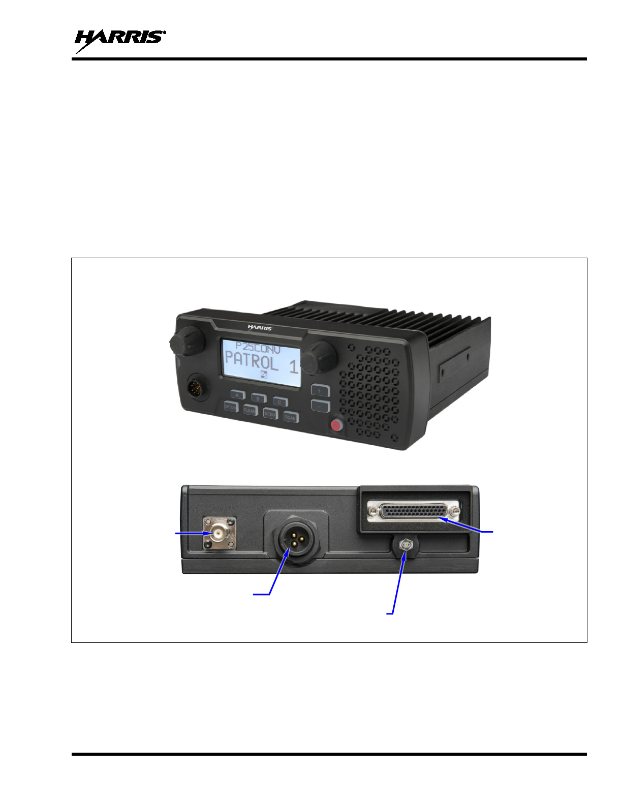
FRONT VIEW
REAR VIEW
Figure 3-1: XG-25M Mobile Radio — Front and Rear Views
The XG-25M radio is designed to operate in a mobile environment, typically within a motor vehicle. It
must be connected to an external transmit/receive antenna such as one mounted to the vehicle’s rooftop or
trunk lid. Several different types of external-mount antennas are approved and available for use with the
radio, as listed in Table 4-3 (page 13), and in the XG-25M radio’s Product Safety Manual.
Antenna
Connector
(female TNC)
DC Power Connector
(3 pins)
GPS Antenna Port
(optional; female SMA)
44-Pin I/O
Connector
14221-1510-4440
10
The radio provides half-duplex voice and data communications. Voice communications are accomplished
via a “push-to-talk” (PTT) type microphone and an external speaker connected to the radio.
The radio features a large text and graphics-based liquid-crystal display (LCD), and front panel controls
for user control of the radio.
The XG-25M must be powered by an external +13.6-volt (nominal) DC power source. In mobile
applications, the motor vehicle’s electrical system is utilized as the source of DC power. Specifications
are included in Section 2 of this manual.
The XG-25M may be equipped with an optional built-in Global Positioning System (GPS) tracking
receiver. The GPS antenna can be integrated into the mobile transmit/receive antenna (i.e., a
“combination” antenna). Alternately, the GPS antenna can be located/mounted completely separate from
the mobile transmit/receive antenna.
The XG-25M exceeds many tough environmental specifications included within military standard
MIL-STD-810G, the radio industry standard TIA/EIA-603, and the radio standard established by the U.S.
Forest Service.
The radio supports operation on APCO Project 25 compliant Common Air Interface (P25 CAI) radio
networks, and operation in a talk-around mode in accordance with the APCO Project 25. P25 radio
systems utilize Improved Multi-Band Excitation (IMBE) speech and data compression technology,
developed by Digital Voice Systems, Inc.
Harris recommends the buyer use only an authorized representative to install and
service this product. The warranties provided to the buyer under the terms of sale shall
be null and void if this product is installed or serviced improperly, and Harris will have
no further obligation to the buyer for any damage caused to the product or to any person
or personal property.
3.2 RADIO PROGRAMMING
Unless otherwise stated, all radio installation and test procedures presented in this manual assume the
radio has been programmed by radio network administration personnel before it is delivered to radio
installation personnel.
Radio Personality Manager (RPM) software application TQS3385 (part number SK-104768-001) is used
to program the XG-25M mobile radio for trunked radio systems. TQS3385 can also be used to program
the radio for analog conventional and P25 conventional operations. For additional information, refer to
RPM’s built-in online help and/or RPM Software Release Notes, publication number MS-012550-001.
Conventional RPM software application TQS3389 (part number SK-012177-001) is used to program the
XG-25M mobile radio for analog conventional and P25 conventional operations. Trunking mode
programming is disabled in TQS3389. For additional information, refer to RPM’s built-in online help
and/or Conventional RPM Software Release Notes, publication number MS-012761-001.
Both RPM applications can also be used to flash program new operating software (i.e., firmware) into an
XG-25M mobile radio. Refer to the radio’s maintenance manual for additional information.
Both RPM applications also support other radios such as the M7100, M7200, M7300, and Unity
XG-100M mobile radios, and the P7100, P7200, P7300, Unity XG-100P, XG-75 and XG-25P portable
radios.
RPM Release R9A or later is required for XG-25M mobile radio programming.
CAUTION
NOTE

14221-1510-4440
11
3.3 RELATED PUBLICATIONS
The following publications contain additional information about the XG-25M mobile radio:
•
Quick Guide:
14221-1510-1000
•
Operator’s Manual:
14221-1510-2000
•
Product Safety Manual: 14221-1510-4000
•
Maintenance Manual, VHF:
14221-1510-5000
The Product Safety Manual and a Quick Guide (for radio operators) are included with each mobile radio
equipment package when it ships from the factory. The Quick Guide and the Operator’s Manual are
available at www.pspc.harris.com without a login. Obtaining a Maintenance Manual or this Installation
Manual from that web site requires an Information Center log-in, then browsing to Tech Link’s Technical
Manual Library.
3.4 REPLACEMENT PARTS
Replacement parts can be ordered via our Customer Care center. To order replacement parts, call, fax or
e-mail:
United States:
• Phone Number: 1-800-368-3277
• Fax Number: 1-321-409-4393
• E-mail: PSPC_CustomerFocus@harris.com
International:
• Phone Number: 1-434-455-6403
• Fax Number: 321-409-4394
• E-mail: PSPC_InternationalCustomerFocus@harris.com
3.5 TECHNICAL ASSISTANCE
If any of the radio equipment requires repair, or if there are questions or concerns about the installation of
this equipment, contact the Harris Technical Assistance Center (TAC) using the following telephone
numbers or e-mail address:
• United States and Canada: 1-800-528-7711 (toll free)
• International: 1-434-385-2400
• Fax: 1-434-455-6712
• E-mail: PSPC_tac@harris.com
14221-1510-4440
12
4 UNPACKING AND CHECKING THE EQUIPMENT
4.1 MATERIALS
A typical set of materials for an XG-25M mobile radio installation includes:
• XG-25M Mobile Radio — See Table 4-1 below for catalog and part number.
• Installation Kit DM-ZN9X — See Table 4-2 below for kit contents.
• One or Two Antennas — See Table 4-3. (A second antenna or a “combination” antenna is required if
the optional GPS receiver is installed and used.)
• Microphone — See Table 4-3 for microphone part numbers.
Table 4-1: XG-25M Mobile Radio Catalog and Part Number
CATALOG
NUMBER* RADIO
PART NUMBER DESCRIPTION
DM-MV1B 14015-0010-01 XG-25M VHF (136 to 174 MHz) 50-Watt Mobile Radio
DM-M78B 14015-0020-01 XG-25M Dual-Band 700/800 MHz 35-Watt Mobile Radio
* In addition to the radio, each catalog package also contains a Product Safety Manual and a Quick Guide.
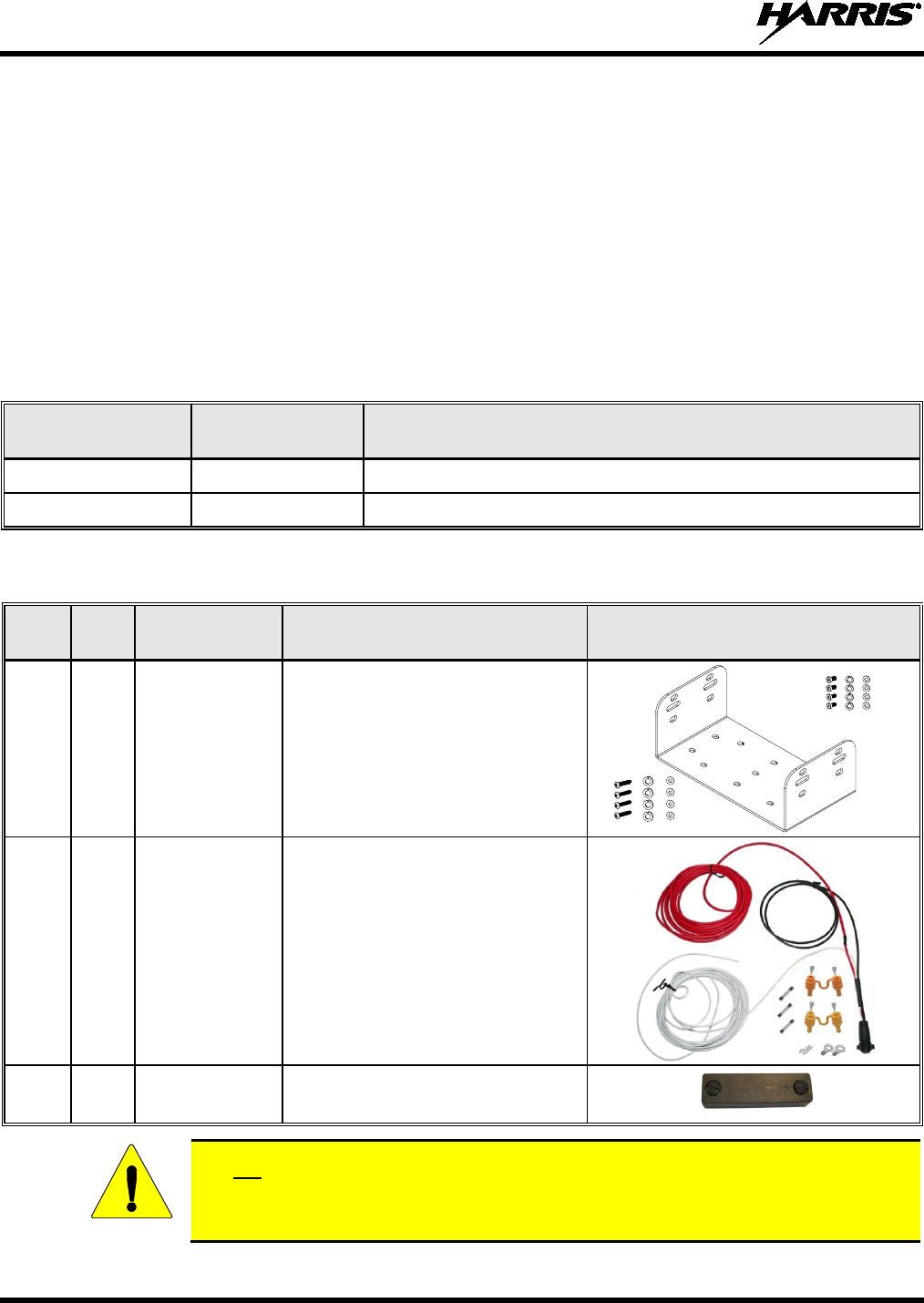
Table 4-2: Installation Kit DM-ZN9X for XG-25M Mobile Radio
ITEM QTY. PART
NUMBER DESCRIPTION ILLUSTRATION
1 1
14015-0201-01 Kit, Front-Mount Mounting Bracket
2 1
CA-012365-
001 Cable, DC Power. Includes
10-AWG, 20-Foot DC Power Cable
with straight connector, (2)
waterproof HFB fuse holders, (1)
20-amp AGC fuse, (1) 15-amp
AGC fuse, and (1) 3-
amp AGC
fuse
3 1
FM-104859-
004 Cover, Waterproof
Do not use the 20-amp fuse included with DC Power Cable CA-012365-001. Radio
main power should be protected with the 15-amp fuse included with the cable. Refer to
Section 13 for additional information.
CAUTION
14221-1510-4440
13
4.2 MATERIAL INSPECTION
After removal from the carton, examine the radio and other components for broken,
damaged, loose or missing parts. If any are noted, contact the Customer Care center (see
page 11) immediately to discuss and arrange the return of the equipment to Harris for
replacement. Any unauthorized attempts to repair or modify this equipment will void
the warranty and could create a safety hazard.
Upon removing items from the carton and verifying that all equipment is accounted for, proceed with the
installation.
Mounting of the radio and/or antenna in ways other than those described in this manual
may adversely affect performance, violate FCC rules on RF exposure, and even damage
the unit, posing a potential safety hazard.
Table 4-3: Additional Options and Accessories for XG-25M Mobile Radios
PART NUMBER DESCRIPTION
AN-125001-001 Antenna Mount: Standard Rooftop, NMO Mounting Base, 15-foot (4.6-meter)
RG-58 A/U (or equivalent) Low-Loss RF Cable, Male TNC RF Connector
AN-125001-002
Antenna Mount: Standard Rooftop, NMO Mounting Base, 15-foot (4.6-meter)
RF-195 (or equivalent) Low-Loss RF Cable, Male TNC RF Connector
AN-125001-003 Antenna Mount: Thick Rooftop, NMO Mounting Base, 15-foot (4.6-meter)
RG-58 A/U (or equivalent) Low-Loss RF Cable, Male TNC RF Connector
AN-125001-004 Antenna Mount: Thick Rooftop, NMO Mounting Base, 15-foot (4.6-meter) RF-195
(or equivalent) Low-Loss RF Cable, Male TNC RF Connector
AN-125001-005 Antenna Mount: GPS Combo, Standard Rooftop, NMO Mounting Base, 17-foot (5.1-
meter) RF-195 (or equivalent) Low-Loss RF Cable, Male TNC RF Connector; 17-foot
(5.1-meter) RG174/U (or equivalent) GPS RF Cable with Male SMA RF Connector
(attached); 2.7 to 3.3 Vdc or 4.8 to 5.2 Vdc Bias
AN-125001-006 Antenna Mount: GPS Combo Rooftop, NMO Mounting Base, 17-foot (5.1-meter)
RF-195 (or equivalent) Low-Loss RF Cable, Male TNC RF Connector; 17-foot
(5.1-meter) RG174/U (or equivalent) GPS RF Cable with Male SMA RF Connector
(attached); 2.7 to 3.3 Vdc or 4.8 to 5.2 Vdc Bias
AN-125001-007 Antenna Mount: Magnetic, NMO Mounting Base, 15-foot (4.6-meter) RG-58 A/U (or
equivalent) Low-Loss RF Cable, Male TNC RF Connector
AN-125001-008 Antenna Mount: Magnetic, NMO Mounting Base, 15-foot (4.6-meter) RF-195 (or
equivalent) Low-Loss RF Cable, Male TNC RF Connector
AN-225002-001 Antenna Element: 136 to 174 MHz, 0 dBd Gain, NMO, Factory-Tuned
AN-225002-003 Antenna Element: 136 to 174 MHz, 3 dBd Gain, NMO, Field-Tuned*
AN-225002-004 Antenna Element: 136 to 174 MHz, 2.4 dBd Gain, NMO, Field-Tuned*
AN-225006-001 Antenna Element: 132 to 960 MHz, 0 dBd Gain, NMO, Field-Tuned*
AN-225001-001 Antenna Element: 700/800 MHz, 3 dBd Gain, NMO, Factory-Tuned
AN-225001-002 Antenna Element: 700/800 MHz, 3 dBd Gain, Elevated-Feed, NMO, Factory-Tuned
AN-225001-003 Antenna Element: 700/800 MHz, 3 dBd Gain, Elevated-Feed No Ground Plane,
NMO, Factory-Tuned
CAUTION
CAUTION
14221-1510-4440
14
Table 4-3: Additional Options and Accessories for XG-25M Mobile Radios
PART NUMBER DESCRIPTION
AN-225001-004 Antenna Element: 700/800 MHz, 2 dBd Gain, Low-Profile, NMO, Factory-Tuned
AN-225001-005 Antenna Element: 700/800 MHz, 5 dBd Gain, NMO, Factory-Tuned
AN-025187-001 Antenna, GPS Receive Only, Roof-Mount, 17-foot (5.2-meter) RG174/U (or
equivalent) RF Cable with Male SMA RF Connector (attached); 2.7 to 3.3 Vdc or 4.8
to 5.2 Vdc Bias
AN-025187-003 Antenna, GPS Receive Only, Magnetic-Mount, 17-foot (5.2-meter) RG174/U (or
equivalent) RF Cable with Male SMA RF Connector (attached); 2.7 to 3.3 Vdc or 4.8
to 5.2 Vdc Bias
14002-0174-08 Cable, Option. See page 38.
14015-0200-01 Cable, Front Panel Programming. See page 43.
CA-013671-020 Cable, Serial Data (20 feet). See page 42.
CN-014756 Connector, RF; TNC Male Crimp-Type for RG-58A/U, RG-58/U, RGU/400, YR29586-9,
YR29586-10 and Pro-Flex™ Plus 195 Coaxial Cable
MC-101616-060 Microphone, Standard
LS102824V10 Speaker, External Mobile; 20-Watt (with 4.6-foot cable). See Section 8 on page 36.
* Element must be trimmed to proper length in order to minimize antenna system VSWR.
14221-1510-4440
15
5 PLANNING THE INSTALLATION
5.1 GENERAL INFORMATION
Before starting, plan the installation carefully so it will meet the following requirements:
• The installation is safe for the operator and passengers within the vehicle.
• The equipment is installed away from the airbag deployment areas.
• The installation allows for convenient access by the operator, as applicable.
• The equipment is protected from water damage.
• The installation is neat and allows easy service access.
• The mobile radio is mounted in a location assuring the vehicle occupants’ safety and out of the way
of passengers and auto mechanics.
A professional radio installer should perform the installation!
5.2 TOOLS REQUIRED
The following tools are recommended to complete the installation. Where specific vendor names and
model or part numbers are given, equivalent substitutes may be used:
• Non-Insulated Crimp Tool: Thomas & Betts
WT-111-M
• Phillips-Head Screwdrivers, #1 and #2
• Flat-Blade Screwdrivers, #1 and #2
• Insulated Terminal Crimp Tool: Klein 1005 • 3-Millimeter Hex Key Wrench
• Fuse Holder Crimp Tool: Thomas & Betts –
WT-112M or California Terminal Products
No. 1250 or Channelock No. 909
• 5/16-Inch Combination or Open-End Wrench
(Only Needed for GPS Receiver Option)
• 3-Blade Coax Cable Stripper for RG-58 Cable
similar to Tyco Electronics 1490490-1
(includes blades)
• ¾-Inch or ⅜-Inch Hole Saw with Depth
Protection: ¾-Inch = Ripley HSK 19 or
Antenex HS34; ⅜-Inch = Antenex HS38
• Ratcheting Hex-Crimp Tool for 50-Ohm TNC
and BNC RF Connectors and RG-58 Cable
similar to Tyco Electronics 58433-2 (includes
Crimper 354940-1 and Die Set 58436-1) or
Emerson Network Power 24-9960P
• Clutch-Type Cordless Drill with Drill Bits and
Driver Bits
• Deburring Tool (for ⅜-inch and smaller holes)
• Flush-Cut and Large Wire Cutters
• Non-Metallic Fish Tape, 25-Foot: Klein-Lite
50156 • Various Fasteners (e.g., machine screws and
nuts, Tek screws, etc.)
• Various Socket and Driver Sets • Tie Wraps: Nylon, 6-inches or larger
•
Soft-Jaw Pliers: Tessco 450520 or equivalent
A separate list of test equipment is included in Section 14.1 on page 47.
CAUTION
NOTE
14221-1510-4440
16
5.3 LOCATING COMPONENTS
Plan the mounting locations of all components (radio, antenna, and cables) and determine the routes for
all wiring and cables. Particularly consider the connection of the radio for planning purposes.
• Determine the customer’s preferences, if any, for location of components. Comply with these
preferences as long as they are consistent with safety recommendations and guidelines presented in
this manual, the Product Safety Manual, and other generally accepted professional radio installation
practices.
• The radio may be mounted below or above the vehicle’s dash, or at some other location per customer
requirements, available space, and/or mounting surface strength. Dimensions for the radio are listed
in Section 2.1 on page 6. As noted in that section, these dimensions do not include space required at
the rear of the radio for cables. Several inches of clearance space is required.
• When selecting a mounting location, verify sufficient clearance behind the radio can be maintained so
cables will not be stressed, crushed, twisted, or bent at severe angles. Also, the front and sides of the
radio must have clearance for air circulation, access to mounting screws, mounting hardware, etc.
• Verify the drilling of holes and the insertion of screws will not damage or interfere with any existing
vehicle components (for example, a fuel tank, fuel lines, the transmission housing, etc.), or any
existing vehicle wiring.
• For antenna location and installation-related information, refer to Section 6.
The radio must be kept out of direct sunlight and away from heat sources. Adequate
free-air ventilation must be provided to its cooling fins. The radio will automatically
reduce its transmit
RF output power when its ambient temperature exceeds
approximately +140° Fahrenheit (+60° Celsius).
All cables should have a service loop near each connector end. Do not bend the cables
at severe angles near the connector end. Above all, after all components are installed,
verify no cable is under any tension. Failure to do so may lead to damaged cables,
causing intermittent radio operation or complete radio failure.
CAUTION
CAUTION
14221-1510-4440
17
6 ANTENNA INSTALLATION
6.1 ANTENNA MOUNTING LOCATIONS
Review all Regulatory and Safety Information presented in the radio’s Product
Safety Manual. A transmitting antenna must be installed in accordance with the
guidelines presented in both the Product Safety Manual and this manual. The
Product Safety Manual is included in the radio eq
uipment package when the
package ships from the factory.
As a guide for determining the best possible mounting location in order to reduce human exposure to
radio frequency (RF) electromagnetic energy during transmit mode, refer to the following:
• For a 50-Watt VHF Radio: See Figure 6-1 (page 18)
• For a 35-Watt 700/800 MHz Radio: See Figure 6-2 (page 20)
Also refer to the respective Recommended Minimum Safe Lateral Distance table
presented in the Product Safety Manual. These tables list the recommended minimum
safe distance
for a controlled environment and for unaware bystanders in an
uncontrolled environment, from transmitting antennas (i.e., monopoles over a ground
plane, or dipoles) at rated radio power for mobile radios installed in a vehicle.
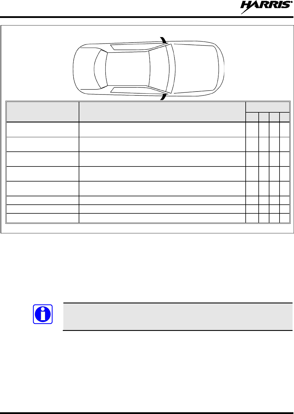
Antennas must be mounted in one of four (4) possible locations on the vehicle. Figure 6-1 and Figure 6-2
shows the recommended locations and antenna part numbers. Also, see Table 4-3 for additional
information. Always follow the antenna manufacturer’s instructions when mounting an antenna.
6.1.1 Direct Center or Center-Rear of Rooftop
The center of the vehicle’s roof is the best location for a rooftop-mount antenna (location in the
following figures). For optimal performance, the mounting area under the antenna must be flat with a
minimum radius of six (6) inches of metal ground plane. It must be located directly in the center of the
roof to minimize human exposure to RF electromagnetic energy. Other obstructions such as a light bar or
another antenna may prevent the antenna from being mounted in the direct center of the roof. In this case,
the antenna should be mounted a minimum of one foot away from and behind the obstruction but in the
middle of the roof with respect to the left and right sides of the vehicle (location in the following
figures).
6.1.2 Center of Trunk Lid
Certain vehicles do not allow for the antenna to be placed in the center or center-rear of the roof. In this
case, the next best location for the antenna is in the direct center of the trunk lid (location in the
following figures). In this case, an elevated-feed-point antenna is recommended. Although this type of
antenna does not require a metal ground plane, it must be located directly in the center of the trunk lid to
minimize human exposure to RF electromagnetic energy.
6.1.3 Rear Deck Lid for Stand-Alone GPS Receive Antenna
If the XG-25M mobile radio does not use a GPS combination-type antenna and it is equipped with a GPS
receiver, a stand-alone GPS receive antenna must be separately located and mounted. The vehicle’s rear
deck lid (location in the following figures) is the recommended mounting location for this case. This
locates the GPS antenna inside the vehicle.
WARNING
NOTE
14221-1510-4440
18
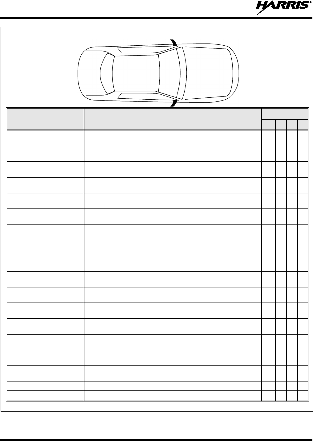
TOP VIEW OF A TYPICAL VEHICLE
ANTENNA
PART NUMBER ANTENNA DESCRIPTION* LOCATION(S)
AN-125001-001 (mount) with
AN-225002-001 (element) 136 to 174 MHz, Standard Rooftop-Mount, 0 dBd Gain
AN-125001-001 (mount) with
AN-225006-001 (element) 132 to 960 MHz, Standard Rooftop-Mount, 0 dBd Gain,
¼-Wavelength, Field-Tuned
AN-125001-001 (mount) with
AN-225002-003 (element) 136 to 174 MHz, Standard Rooftop-Mount, 3 dBd Gain
AN-125001-001 (mount) with
AN-225002-004 (element) 136 to 174 MHz, Standard Rooftop-Mount, 2.4 dBd Gain
AN-125001-003 (mount) with
AN-225002-001 (element) 136 to 174 MHz, Thick Rooftop-Mount, 0 dBd Gain
AN-125001-003 (mount) with
AN-225006-001 (element) 132 to 960 MHz, Thick Rooftop-Mount, 0 dBd Gain, ¼-Wavelength,
Field-Tuned
AN-125001-003 (mount) with
AN-225002-003 (element) 136 to 174 MHz, Thick Rooftop-Mount, 3 dBd Gain
AN-125001-003 (mount) with
AN-225002-004 (element) 136 to 174 MHz, Thick Rooftop-Mount, 2.4 dBd Gain
AN-125001-005 (mount) with
AN-225002-001 (element) 136 to 174 MHz, GPS Combo Standard Rooftop-Mount, 0 dBd Gain
AN-125001-005 (mount) with
AN-225006-001 (element) 132 to 960 MHz, GPS Combo Standard Rooftop-Mount, 0 dBd Gain,
¼-Wavelength, Field-Tuned
AN-125001-005 (mount) with
AN-225002-003 (element) 136 to 174 MHz, GPS Combo Standard Rooftop-Mount, 3 dBd Gain
AN-125001-005 (mount) with
AN-225002-004 (element) 136 to 174 MHz, GPS Combo Standard Rooftop-Mount, 3 dBd Gain
AN-125001-007 (mount) with
AN-225002-001 (element) 136 to 174 MHz, Magnetic-Mount, 0 dBd Gain
AN-125001-007 (mount) with
AN-225006-001 (element) 132 to 960 MHz, Magnetic-Mount, 0 dBd Gain, ¼-Wavelength, Field-
Tuned
AN-125001-007 (mount) with
AN-225002-003 (element) 136 to 174 MHz, Magnetic-Mount, 3 dBd Gain
AN-125001-007 (mount) with
AN-225002-004 (element) 136 to 174 MHz, Magnetic-Mount, 2.4 dBd Gain
AN-025187-001 GPS Receive Only, Roof-Mount
AN-025187-003 GPS Receive Only, Magnetic-Mount
* See Table 4-3 on page 13 for detailed antenna descriptions.
Figure 6-1: Recommended VHF Antenna Mounting Locations with Antenna Part Numbers
Trunk
Lid Rooftop
Hood
VHF
Applications
14221-1510-4440
19
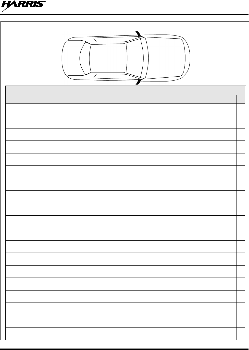
TOP VIEW OF A TYPICAL VEHICLE
ANTENNA
PART NUMBER ANTENNA DESCRIPTION* LOCATION(S)
AN-125001-002 (mount) with
AN-225006-001 (element) 132 to 960 MHz Standard Rooftop-Mount, 0 dBd Gain, ¼-Wavelength,
Field-Tuned
AN-125001-002 (mount) with
AN-225001-001 (element) 700/800 MHz Standard Rooftop-Mount, 3 dBd Gain
AN-125001-002 (mount) with
AN-225001-002 (element) 700/800 MHz Elevated-Feed Standard Rooftop-Mount, 3 dBd Gain
AN-125001-002 (mount) with
AN-225001-003 (element) 700/800 MHz Elevated-Feed No Ground Plane Standard Rooftop-
Mount, 3 dBd Gain
AN-125001-002 (mount) with
AN-225001-004 (element) 700/800 MHz Low-Profile Standard Rooftop-Mount, 2 dBd Gain
AN-125001-002 (mount) with
AN-225001-005 (element) 700/800 MHz Standard Rooftop-Mount, 5 dBd Gain
AN-125001-004 (mount) with
AN-225006-001 (element) 132 to 960 MHz Thick Rooftop-Mount, 0 dBd Gain, ¼-Wavelength,
Field-Tuned
AN-125001-004 (mount) with
AN-225001-001 (element) 700/800 MHz Thick Rooftop-Mount, 3 dBd Gain
AN-125001-004 (mount) with
AN-225001-002 (element) 700/800 MHz Elevated-Feed Thick Rooftop-Mount, 3 dBd Gain
AN-125001-004 (mount) with
AN-225001-003 (element) 700/800 MHz Elevated-Feed No Ground Plane Thick Rooftop-Mount,
3 dBd Gain
AN-125001-004 (mount) with
AN-225001-004 (element) 700/800 MHz Low-Profile Thick Rooftop-Mount, 2 dBd Gain
AN-125001-004 (mount) with
AN-225001-005 (element) 700/800 MHz Thick Rooftop-Mount, 5 dBd Gain
AN-125001-006 (mount) with
AN-225006-001 (element) 132 to 960 MHz Thick Rooftop-Mount, 0 dBd Gain, ¼-Wavelength,
Field-Tuned
AN-125001-006 (mount) with
AN-225001-001 (element) 700/800 MHz GPS Combo Rooftop-Mount, 3 dBd Gain
AN-125001-006 (mount) with
AN-225001-002 (element) 700/800 MHz GPS Combo Elevated-Feed Rooftop-Mount, 3 dBd Gain
AN-125001-006 (mount) with
AN-225001-003 (element) 700/800 MHz GPS Combo Elevated-Feed No Ground Plane Rooftop-
Mount, 3 dBd Gain
AN-125001-006 (mount) with
AN-225001-004 (element) 700/800 MHz GPS Combo Low-Profile Rooftop-Mount, 2 dBd Gain
AN-125001-006 (mount) with
AN-225001-005 (element) 700/800 MHz GPS Combo Rooftop-Mount, 5 dBd Gain
AN-125001-008 (mount) with
AN-225001-001 (element) 132 to 960 MHz Magnetic-Mount, 0 dBd Gain, ¼-Wavelength, Field-
Tuned
Trunk
Lid
Rooftop
Hood
700/800 MHz
Applications
14221-1510-4440
20
TOP VIEW OF A TYPICAL VEHICLE
ANTENNA
PART NUMBER ANTENNA DESCRIPTION* LOCATION(S)
AN-125001-008 (mount) with
AN-225001-001 (element) 700/800 MHz Magnetic-Mount, 3 dBd Gain
AN-125001-008 (mount) with
AN-225001-002 (element) 700/800 MHz Magnetic-Mount Elevated-Feed, 3 dBd Gain
AN-125001-008 (mount) with
AN-225001-003 (element) 700/800 MHz Magnetic-Mount Elevated-Feed No Ground Plane, 3 dBd
Gain
AN-125001-008 (mount) with
AN-225001-004 (element) 700/800 MHz Magnetic-Mount Low-Profile, 2 dBd Gain
AN-125001-008 (mount) with
AN-225001-005 (element) 700/800 MHz Magnetic-Mount, 5 dBd Gain
AN102800V1 (Discontinued) 136 to 941 MHz Standard Rooftop-Mount, ¼-Wave, 0 dBd Gain
AN-025187-001 GPS Receive Only, Roof-Mount
AN-025187-003 GPS Receive Only, Magnetic-Mount
* See Table 4-3 on page 13 for detailed antenna descriptions.
Figure 6-2: Recommended 700/800 MHz Antenna Mounting Locations with Antenna Part Numbers
6.2 ANTENNA INSTALLATION PROCEDURES
An antenna must be installed before completing the radio installation.
Table 4-3 (page 13), Figure 6-1 and Figure 6-2 list the mobile radio antennas available for use with the
respective radio. As presented in the previous section, various mounting locations exist. Optimal
performance is achieved via a rooftop antenna mounted in the direct center of the motor vehicle’s roof.
NOTE
Trunk
Lid
Rooftop
Hood
700/800 MHz
Applications
14221-1510-4440
21
6.2.1 Installing NMO Antenna Mounts AN-125001-001 and 003
These NMO style antenna mounts can each be used with several different antenna elements. Only limited
access under the mounting location is typically required. The installation procedure is presented in
Section 6.2.1.3.
6.2.1.1 Standard NMO Antenna Mount AN-125001-001
This standard ¾-inch NMO antenna mount requires a ¾-inch hole in a relatively flat area of the vehicle
body, with a vehicle metal thickness of between 0.020 and 0.040 inches.
6.2.1.2 Thick-Roof NMO Antenna Mount AN-125001-003
This thick-roof NMO antenna mount uses either a ⅜-inch or a ¾-inch mounting hole in a relatively flat
area of the vehicle body, with a vehicle metal thickness of between 0.040 and 0.1875 inches (3/16-inch
maximum thickness).
For thick-roof NMO antenna mount AN-125001-003, using a ⅜-inch mounting hole
requires better access to the underside of the mounting location than if a ¾-inch hole is
used. This is because, in the case of a ⅜-inch hole, the antenna mount’s bushing
assembly must be inserted from the underside of the mounting surface.
When using a ¾-inch mounting hole to mount thick-roof NMO antenna mount
AN-125001-003, the thickness of the mounting surface must be at least ⅛-inch
(0.125-inch minimum thickness
). This requirement is due to the thickness of the
alignment ring used to center the bushing assembly within the ¾-inch mounting hole.
6.2.1.3 Installation Procedure for Mounts AN-125001-001 and -003
1. Select the antenna mounting location in accordance with the information presented in Section 6.1 of
this manual. If necessary, contact the Technical Assistance Center for assistance. See page 11 for
TAC contact information.
2. Verify no obstructions exist immediately below the respective mounting location on the underside of
the vehicle body, such as vehicle ribbing/body framing, a wiring harness, air bag equipment, etc. Also
verify there is a sufficient access path and clearance for the mount’s coax cable. If there is an
obstruction or insufficient clearance, select another nearby mounting location.
3. Measure and mark the center point of the selected antenna mounting location. Be sure to center the
mark from side-to-side of the vehicle.
4. Obtain a hole saw specifically designed for drilling NMO mounting holes of the required diameter.
(e.g., Antenex/Laird Technologies model HS34 or equivalent for a ¾-inch hole; Antenex/Laird
Technologies model HS38 or equivalent for a ⅜-inch hole).
5. If the vehicle’s headliner panel, carpet, seats, or otherwise, is below the mounting location, move or
remove the headliner panel, etc. as necessary to protect it. Alternately, apply a heat-resistant mask
material (such as a fiberglass mat or thin sheet metal with masked edges) as required to “catch” the
metal shavings and the metal plug (if any) produced by the hole saw. The plug (if any) may be
relatively hot if/when it drops out of the saw upon completion of the hole drilling process. ⅜-inch
diameter hole saws generally produce only shavings, not plugs.
6. With the hole saw and a drill, drill a hole at the marked hole center point. Position the drill square to
(i.e., 90 degrees from) the vehicle mounting surface so paint immediately outside of the perimeter of
the hole is evenly removed.
NOTE
14221-1510-4440
22
Excessive use of the hole saw and/or failure to position the drill “square” with
(i.e., at a 90-degree angle from)
the vehicle mounting surface may result in
damage to the metal mounting surface, in the area immediately outside of the
perimeter of the hole.
7. Ensure the saw removed the paint immediately around the hole as the drilling operation completes. If
not, do so by reinserting the saw completely into the hole and spinning it as required. This allows
proper grounding via the mount’s lock nut on the top of the mounting surface. On the bottom of the
mounting surface, the “teeth” of the mount’s bushing assembly may not provide a good ground due to
thick vehicle undercoating, thick primer, oxidation/rust, etc.
8. For a ¾-inch hole, feed the unterminated end of the mount’s coax cable into the hole from the top
surface of the vehicle until the mount’s bushing assembly is in position to drop into the hole. The
bushing should be tilted at a slight angle and fed into the hole. The threaded shank of the mount’s
bushing assembly will not fall through a ¾-inch hole.
For a ⅜-inch hole, feed the threaded shank of the mount’s bushing assembly into the hole from the
underside of the mounting surface. Hold it into position until the lock nut is installed.
9. If installing a thick-roof antenna mount (⅜-inch shank) into a ¾-inch hole, place the alignment ring
onto the threaded shank of the mount. This ring has an approximate ¾-inch outside diameter.
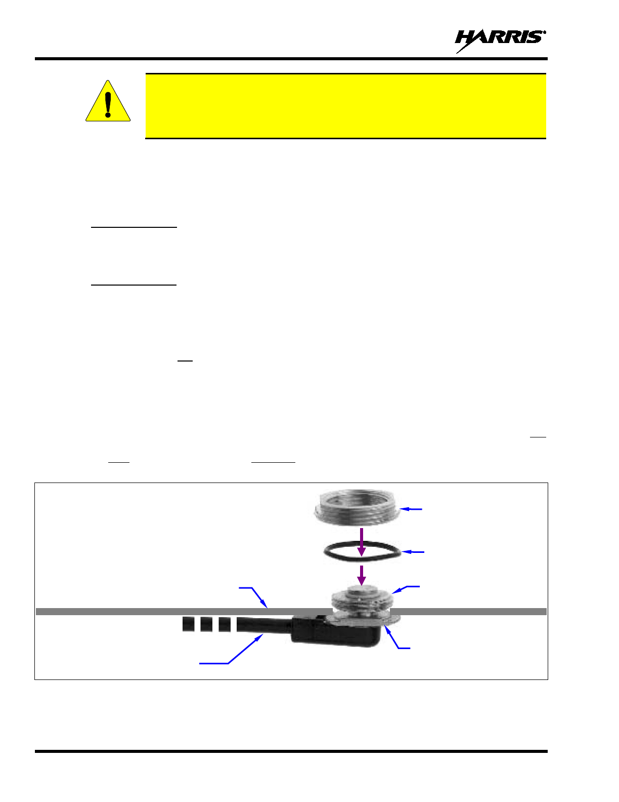
10. A tube of synthetic lubricant is included with the antenna mount. Apply this lubricant to the mount’s
rubber O-ring. Do not get any lubricant on the center contact of the mount’s bushing assembly.
11. As illustrated in Figure 6-3 and Figure 6-4, add the O-ring (C) and lock nut (D) to the top of the
mount’s bushing assembly (A). With the O-ring in the groove in the underside of the lock nut, thread
the lock nut onto the bushing assembly. Be sure the O-ring remains in the groove before tightening
the lock nut.
12. Using a 15/16-inch open-end wrench, tighten the lock nut until it fully compresses the O-ring and
makes good contact with the vehicle mounting surface. The groove’s ridges on the bottom of the lock
nut must make full contact with the unpainted metal surface of the vehicle.
13. Install the antenna element per the procedure in Section 6.2.4.
Figure 6-3: Installing a Standard ¾-Inch NMO Antenna Mount
(e.g., AN-125001-001)
CAUTION
Coax Cable
(Partial)
Rubber O-Ring (C)
Vehicle Mounting Surface
(top side)
Bushing Assembly (A)
Lock Nut (D)
Threaded Shank (B)
14221-1510-4440
23
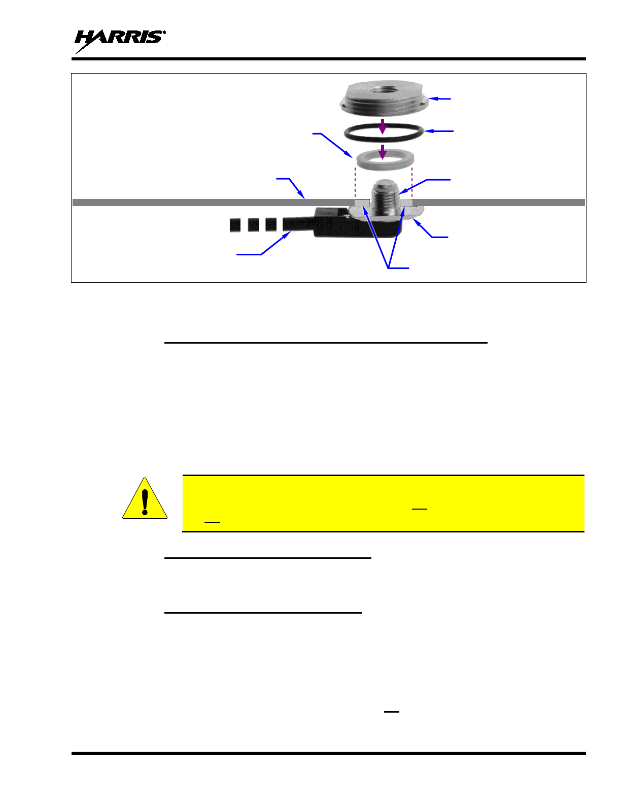
Figure 6-4: Installing a Thick-Roof NMO Antenna Mount
(e.g., AN-125001-003)
6.2.2 Installing NMO Magnetic Antenna Mount AN-125001-007
1. Thoroughly clean the bottom of the magnetic mount and the selected vehicle mounting surface by
removing all dust, dirt, etc.
2. Carefully place the magnet mount onto the metal surface of the vehicle at the selected location. The
coax cable exiting the mount’s base should be orientated towards the point at which it will enter into
the interior of the vehicle. Do not try to reposition it by sliding it on a painted metal surface.
3. Route the mount’s coax cable to the radio location, passing it by the trunk lid’s perimeter gasket, door
perimeter gasket, etc., as necessary.
4. Install the antenna element per the procedure in Section 6.2.4.
To remove a magnetic antenna mount, hold it at the bottom of its base and tilt it at an
angle to release the magnetic attraction force. Do not pull on the mount’s coax cable.
Do not drag the mount across the mounting surface.
6.2.3 Installing All Other Antenna Mounts
For any other type of antenna mount not covered in the previous sections, such as GPS combination
antennas, install the mount in accordance with the installation instructions included with the mount.
6.2.4 Attaching NMO Antenna Elements
1. Clean the top surface of the NMO mount and the surface of the vehicle immediately around the
mount.
2. Place the gasket included with the antenna element (not pictured in Figure 6-3 or Figure 6-4) around
the mount and against the surface of the vehicle. If a lubricant or sealant was included with the
gasket, apply it to the gasket before placing the gasket.
3. Apply the antenna element to the top of the mount and tighten it in a clock-wise direction (as viewing
from the top). Use an appropriate wrench if required. Do not over-tighten.
CAUTION
Coax Cable
(Partial)
Rubber O-Ring (C)
Vehicle Mounting Surface
(top side)
Bushing Assembly (A)
Lock Nut (D)
Threaded Shank (B)
Alignment Ring
(Used only with ¾-inch mounting hole)
(Extensions shown to illustrate a
⅜-Inch hole vs. a ¾-inch hole.)
14221-1510-4440
24
4. Install a placard (not supplied) on the vehicle’s dash panel, in accordance with the following
CAUTION. Place the placard in plain view of the vehicle operator’s position.
Before entering any automatic vehicle (“car”) wash equipment, remove the antenna
element from the antenna mount, and secure the element in a safe location inside the
vehicle. This will prevent the wash equipment from damaging the element and/or
mount. After exiting the wash equipment, thoroughly dry the top of the mount before
re-installing the element.
5. Continue with the connection procedure presented in the next section.
6.2.5 Installing the Coax Cable and TNC RF Connector
1. Route the coax cable from the antenna mount to the location where the mobile radio will be installed.
Remove headliner panel, interior panels, etc., as necessary. The cable must be kept out of casual
contact from persons within the vehicle. Tie and stow the cable as necessary to protect it from
possible chafing. Observe and follow this WARNING:
Do not cut an antenna cable any shorter than six (6) feet (1.83 meters), as measured
from the base of the antenna mount to the TNC connector that mates to the radio.
2. Using an appropriate crimp tool, crimp the supplied TNC RF connector to the end of the antenna
cable. For crimping instructions, see Figure 6-5 or the instructions supplied with antenna mount.
3. The antenna cable is connected to the radio’s TNC receptacle-type (female) RF connector per a
procedure presented later in this manual. The cable and its TNC connector must be protected from
damage, dirt, and/or metal shavings which may be generated during the mechanical and electrical
installation of the radio. Temporarily tying the connector and cable-end within a small plastic bag is
recommended.
CAUTION
WARNING
14221-1510-4440
25
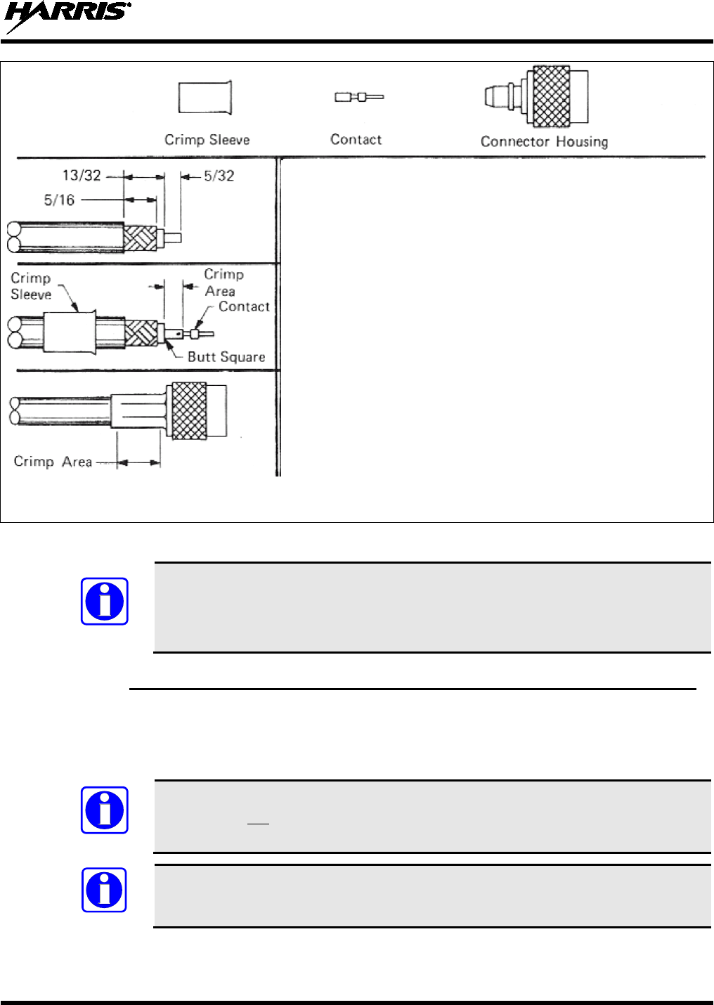
Actual Size; Dimensions are in Inches
(Made From VS-AN-025167-010 Rev. A)
Figure 6-5: Crimping Instructions for TNC RF Connector
If the radio installation includes unity-gain antenna element part number AN-225006-
001, this element must be tuned (trimmed) for maximum performance (i.e., minimum
reflection) during the test procedures presented in Section 14. Other antennas used with
the radio are factory-tuned and therefore do not require tuning in the field.
6.2.6 Install GPS Antenna (Required Only if Radio has GPS Receiver Option)
If the XG-25M radio is equipped with the GPS receiver option, the GPS receiver requires connection to
an externally-mounted GPS antenna. The GPS antenna must be kept at least six (6) inches away from any
other antenna mounted on the vehicle and it must have at least six inches of surface ground plane beneath
it.
Connection to a GPS antenna is only required if the (optional) GPS receiver is installed
in the radio and if its functions will be utilized/required. Refer to Section 11 for
additional information.
A combination (“combo”) antenna kit includes a GPS antenna built into the base of the
mobile antenna. Refer to Table 4-3 (page 13) for available combo antennas.
NOTE
NOTE
NOTE
1. Before cutting the cable to a shorter length, refer to the previous
WARNING. Some antenna cables should never be cut, while others
can be cut to as short as 6 feet.
2. Trim the end of the cable to the dimensions shown at the left, taking
care not to nick the cable’s inner conductor or its braid/shield.
3. Slip the crimp sleeve over the end of the cable, with its flanged-end
facing towards the end of the cable.
4. Place the contact onto the cable’s inner conductor. The end of the
contact and the cable’s inner die
lectric must “butt square” together, as
shown to the left.
5.
While holding the contact tight against the dielectric, crimp the contact
to the inner conductor using an appropriate crimp tool.
6. Flair the cable’s outer braid/shield and then gently but firmly push the
contact (and cable end) into the connector housing until a gentle snap
is felt, indicating the contact is locked in place.
7. Slip the crimp sleeve in place, butting its flanged-end against the
connector housing.
8. Using an appropriate crimp tool, crimp the crimp sleeve securely to
the cable end and connector housing. When crimping, hold the
housing and sleeve firmly together, and to the cable end.
14221-1510-4440
26
6.2.6.1 General Installation Procedure
1. After selecting a mounting location, refer to the antenna manufacturer’s mounting and testing
instructions for installation guidance. Install the antenna in accordance with these instructions. If
necessary, contact the Technical Assistance Center. See page 11 for TAC contact information. Do not
alter the GPS antenna cable length; tie and stow excess cable as necessary.
2. Route the cable from the antenna base to the location of where the radio will be installed. Remove
headliner panel, interior panels, etc., as necessary. The cable must be kept out of casual contact from
persons within the vehicle. Tie and stow it as necessary to protect it from possible chafing.
3. The antenna cable is connected to the radio’s SMA receptacle-type (female) RF connector per a
procedure presented later in this manual (i.e., procedure on page 45). The cable and its (male) SMA
connector must be protected from damage, dirt, and/or metal shavings which may be generated during
the mechanical and electrical installation of the radio. Temporarily tying the connector and cable-end
in a small plastic bag is recommended.
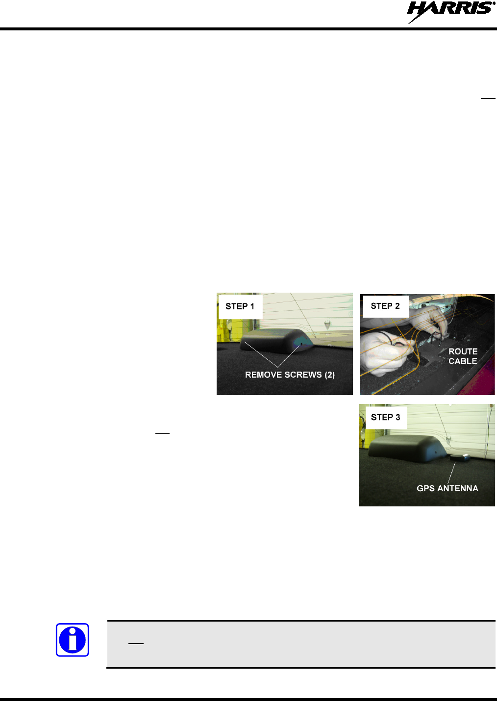
6.2.6.2 Installation Procedure for Inside-Rear-Deck Mounting in Ford Crown Vic
The following GPS antenna installation procedure is recommended for inside-rear-deck mounting of GPS
receive-only antennas, such as AN-025187-001 or AN-025187-003, in a Ford Crown Victoria. Other
vehicle makes/models may use similar installation scenarios:
1. Carefully remove the center rear
brake light assembly by removing
the screws on each side of the
assembly. Lift and set it aside.
2. Route the cable from the GPS
antenna through the rear deck,
next to the cable assembly for the
rear brake light.
3. Position the antenna near the rear glass.
For an antenna that is not a magnetic-
mount, secure it to the deck
near the rear glass in accordance with the instructions provided with
the GPS antenna.
4. Reassemble the rear deck brake light assembly while
using caution
to not to crimp/pinch the GPS coaxial cable.
A small relief notch
may need to be cut in the housing of the light assembly cable
passage.
5.
The cable and its (male) SMA connector must be protected from damage, dirt, and/or metal shavings
which may be generated during the
mechanical and electrical installation of the radio. Temporarily
tying the connector and cable-end in a small plastic bag is recommended.
6. Route the cable to the area near where the radio will be installed.
Tie and stow the antenna cable as
necessary to pre
vent cable chafing or damage from moving items, like the trunk lid’s hinges and
springs. The antenna cable is connected to the radio’s SMA receptacle-
type (female) RF connector
per a procedure presented later in this manual (i.e., procedure on page 45).
Do not alter the length of cable from the GPS antenna. The SMA connector on the end
of the antenna cable is not field-replaceable.
NOTE
14221-1510-4440
27
7 RADIO INSTALLATION
7.1 MOUNTING THE RADIO
The Mounting Bracket Kit for the radio includes a heavy-gauge steel U-shaped mounting bracket. The
radio should be attached to a mounting surface using this bracket. The bracket can be mounted above or
below the radio. Kit contents are shown in Figure 7-2, and bracket dimensions are shown in Figure 7-3.
Both the radio and the mounting bracket have multiple holes in both sides for adjusting the radio within
the bracket. The design allows for both front-to-rear tilting of the radio within the bracket for the best
viewing angle, and a front-to-rear position offset. The radio has four (4) threaded mounting holes, two (2)
per side, and the mounting bracket has twelve (12) corresponding holes, six (6) per side. The radio must
be secured to the bracket using the four M5 socket-head screws included in the Mounting Bracket Kit (2
screws per side).
The radio is approximately front-to-rear centered within the bracket. The radio can be positioned straight
in the bracket (i.e., parallel with the bottom surface of the bracket), or it can be tilted up or down at an
angle of between approximately 15 degrees. When positioned straight in the bracket, the radio extends
approximately 2 inches (5 centimeters) from the front and rear edges of the bracket. In the rear, additional
clearance must be included for cables. The area directly at the front of the radio must be completely clear
of all objects (e.g., gear shift, other radio equipment, etc.) so the operator can easily access and view the
radio.
The mounting bracket must be attached to a secure metal surface that meets or exceeds the minimum
1/16-inch-thick steel sheet metal requirement in accordance with the following WARNING. For example,
it can be attached directly to the bottom of the dash if the gauge of the sheet metal is high and the surface
is firm and flat, or it can be attached to the transmission hump, etc., if a mounting wedge (not included) is
utilized. The radio weighs approximately 6 pounds (2.7 kilograms).
At a minimum, the mounting surface should be 16-gauge (approximately 1/16-inch
thick) steel sheet metal. Mounting to plastic or other material with low tensile and
shear strength could lead to an unsafe and/or failed mounting condition, turning
the radio and its mounting bracket into a projectile during a high-shock incident
such as a motor vehicle accident. If the selected mounting surface does not meet
the minimum 16-gauge steel sheet metal requirement, the surface should be
reinforced with a metal backing plate (not supplied) or it should be reinforced
using some other approved mounting method.
In addition to improving safety of the installation, firm mounting also prevents
unreasonable vibration that could damage the radio, adversely affect transceiver
performance and/or cause its cable connections to loosen. An improperly mounted radio
may experience degradation in the quality of voice and data communications.
WARNING
CAUTION
14221-1510-4440
28
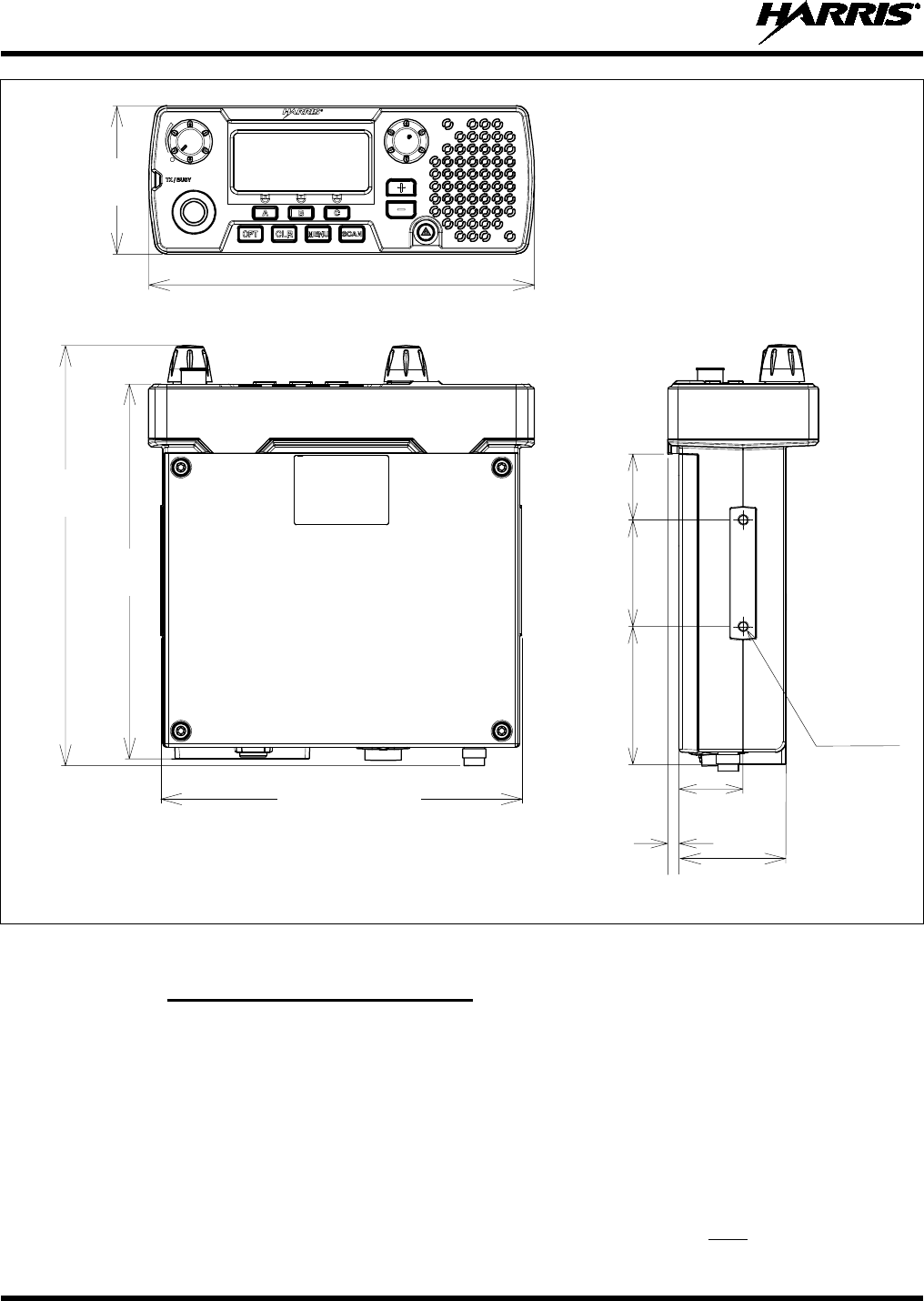
Figure 7-1: XG-25M Radio Dimensions
7.1.1 Mounting Bracket Installation
The radio’s mounting bracket is included with the Mounting Bracket Kit 14015-0201-01. Kit contents
are shown in Figure 7-2. This kit is Item 1 listed in Table 4-2 (page 12).
When selecting a mounting location for the radio, verify sufficient clearance can be maintained around
the radio for installation and service access. A minimum clearance of approximately four (4) inches
(10 centimeters) is recommended at the rear, left and right sides of the radio. As previously stated, the
area directly at the front of the radio must be completely clear of objects so the operator can easily access
and view the radio’s front panel.
As illustrated in Figure 7-3, the bracket is both left-to-right and front-to-rear symmetrical. It has eleven
(11) holes for securing it to a mounting surface. At least four (4) of these holes must be used to secure the
bracket to the mounting surface. Four 1-inch-long #10-32 stainless-steel self-tapping screws are included
7.24 inches
(18.4 centimeters)
2.78 inches
(7.06 cm)
7.04 inches
(17.87 cm)
7.89 inches
(20.03 cm)
2.0 in.
(5.1 cm)
0.315 in. deep
(8.0 cm deep)
M5 Threads
(4 Places)
1.180 in.
(3.0 cm)
0.21 in
(0.53 cm)
6.77 inches
(17.2 centimeters)
1.97 inches
(5.0 cm)
1.22 inches
(3.1 cm)
2.55 inches
(6.48 cm)
14221-1510-4440
29
in the Mounting Bracket Kit for this purpose. However, some other type of hardware (not supplied) may
be used, such as #10-32 stainless-steel self-locking hardware (i.e., machine screws with washers and
locking nuts), or self-drilling screws. Self-drilling screws such as “TEK” screws do not require drilling of
a pilot hole prior to installation. Do not use common self-threading sheet metal screws because they will
loosen over time with vehicle vibrations.
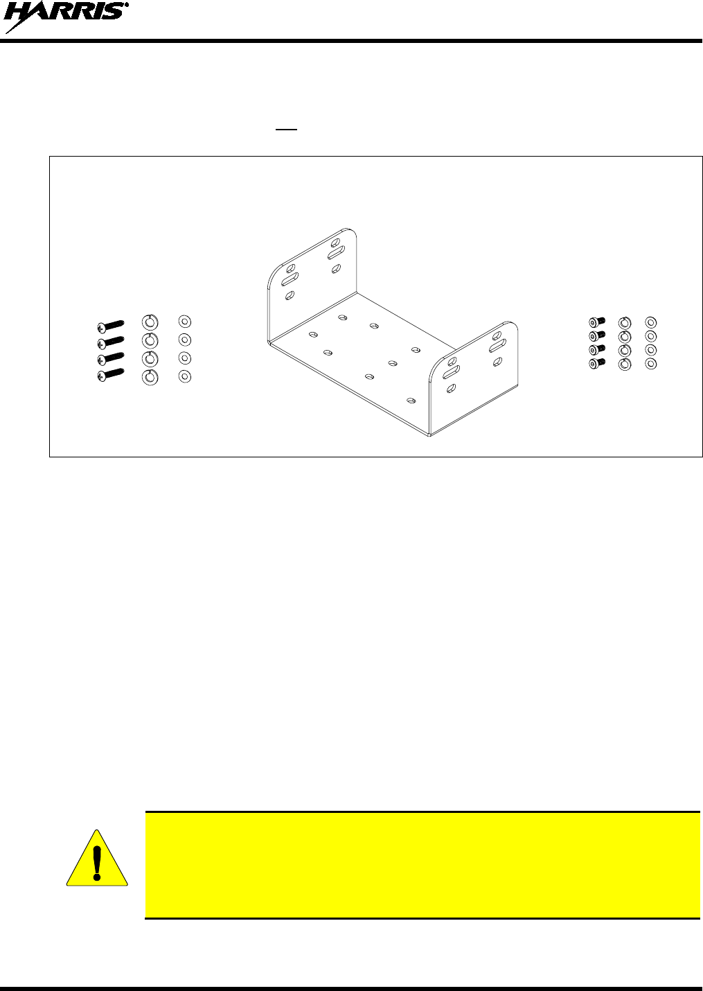
Self-Tapping Screws and
Hardware for Securing Mounting Bracket M5 Hardware for
Bracket to Mounting Surface 14015-0201-02 Securing Radio to Bracket
Figure 7-2: Mounting Bracket Kit 14015-0201-01
The following mounting procedure is recommended:
1. Determine the best radio-to-bracket position and angle by test-fitting the radio into the mounting
bracket at the selected vehicle mounting location. Slide the radio between the sides of the bracket and
temporarily secure it to the bracket with several of the M5 socket-head screws from the bracket kit.
Make any positional adjustments as necessary.
2. At the rear of the radio, verify sufficient clearance is available for cables and service access.
3. If the mounting surface is not flat (such as the top of a transmission hump), construct a suitable
mounting wedge as necessary, and attach the wedge to the surface using an approved attachment
method. Never mount the bracket directly to a non-flat surface.
4. On the mounting surface, mark the selected location for the bracket, and then remove the radio from
the bracket.
5. Clean and remove any foreign material from the mounting surface.
6. Using the bracket as a template, and/or the dimensional information shown in Figure 7-3, mark and
drill at least four (4) mounting holes into the mounting surface as required per the type of hardware
used.
Before drilling holes and/or installing mounting screws, verify these operations will not
damage or interfere with any existing vehicle component (the fuel tank, a fuel line, the
transmission housing, existing vehicle wiring, etc.). Always check to see how far the
mounting screws will extend below the mounting surface prior to installation. Always
deburr drilled holes before installing screws.
CAUTION
14221-1510-4440
30
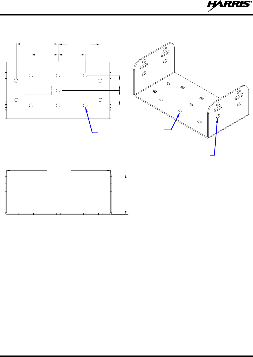
TOP VIEW ISOMETRIC VIEW
FRONT/REAR VIEW
(Made From D14015-0201 Rev. -)
Figure 7-3: Mounting Bracket 14015-0201-02 Dimensions (Radio Not Shown)
7. Temporarily remove the bracket and deburr all of the newly drilled holes.
8. If necessary, apply an approved paint or rust-inhibitor at the holes in the mounting surface.
9. Set the bracket back into place.
10. Install and tighten the mounting screws/hardware.
11. Verify the bracket is firmly secured to the mounting surface. A secure mount prevents unreasonable
vibration, which could damage the radio and/or cause its cable connections to loosen.
12. If the rear of the radio is easily accessible when the radio is positioned in the selected position within
the bracket, it is recommended that the radio be temporarily inserted into the bracket. Otherwise, do
not mount the radio into the bracket at this time, because several cable connections must be made at
the rear of the radio.
2.75 Inches
(69.9 mm)
1.77 Inches
(45.0 mm)
2.75 Inches
(69.9 mm)
1.77 Inches
(45.0 mm)
0.98 Inches
(25.0 mm)
0.98 Inches
(25.0 mm)
6.77 Inches
(172.0 mm)
2.63 Inches
(66.8 mm)
Bracket-To-Radio Screw Holes
(12 places, 6 each side)
Bracket-To-Vehicle
Screw Holes (11 places)
14221-1510-4440
31
7.1.2 Inserting the Radio into the Mounting Bracket
The radio should now be inserted into the mounting bracket according to this procedure:
1. Lay the radio into the mounting bracket with the front of the radio facing in the correct direction
(usually towards the rear of the vehicle).
2. Secure the radio to the bracket using the four (4) M5 x 10 mm stainless-steel socket-head screws, flat
washers, and lockwashers. Each screw should have a lockwasher against the screw head and a
flatwasher against the mounting bracket. This hardware is included with the Mounting Bracket Kit.
The kit’s contents are shown in Figure 7-2. The kit is Item 1 listed in Table 4-2 (page 12).
3. Tighten all screws using a 3-millimeter hex key wrench until each lockwasher is fully compressed
and the radio is firm and flush between the brackets.
4. Check the mounting area for proper clearance for cable service looping and for air circulation, plus an
area to secure and rest the excess cable lengths.
Proper mounting is one factor that ensures optimal radio performance. An improperly
mounted radio may experience degradation in the quality of voice and data
communications.
7.2 DC POWER CABLE INSTALLATION
7.2.1 Overview of On/Off Power Wiring Configurations
The following power wiring configurations are supported:
• Radio turns on and off automatically with vehicle’s ignition switch/key — This configuration
allows the on/off state of the vehicle’s ignition switch/key to control the on/off power state of the
radio. The white wire of the radio’s DC Power Cable is connected to a fused switched power source,
typically identified as vehicle “Accessory” power. This source must switch on (up to positive (+)
battery voltage potential) when the vehicle’s ignition switch/key turns on, and it must switch off (to
near zero volts) when the ignition switch/key turns off. The required fuse rating is 3 amperes. When
using this configuration, the on/off/volume control must be left in the on position for automatic
power-up/down to function properly.
• Radio turns on and off with a manual switch — This configuration is used when, for example, the
radio has to remain on even when the ignition key must be removed from the vehicle and a separate
on/off switch is acceptable. The white wire of the radio’s DC Power Cable is connected to one side of
a manually-controlled switch, and the other side of this switch is connected to unswitched and fused
vehicle power. The required fuse rating is 3 amperes. When using this configuration, the
on/off/volume control must be left in the on position for automatic power-up/down to function
properly.
• Radio turns on with its on/off/volume control (“hot wired”) — This configuration allows radio
on/off power control only via its on/off/volume control. It may be desired if, for example, the radio
has to remain on even when the ignition key must be removed from the vehicle and a separate on/off
switch is not desired and/or not acceptable. The white wire of the radio’s DC Power Cable must be
connected to unswitched and fused vehicle power. The required fuse rating is 3 amperes.
In all of the above cases, the radio’s main DC power input (red wire) must be connected through an in-
line fuse to unswitched vehicle DC power. The red wire must be connected to raw battery power (positive
battery terminal) via the supplied fuse.
NOTE
14221-1510-4440
32
7.2.2 DC Power Cable and Main Fuse Holder Installation
The radio’s DC Power Cable has a 3-pin connector, a 20-foot red wire (for the main power connection), a
20-foot white wire (for the switched power source connection), and a 4-foot black wire (for the ground
connection). It is supplied with waterproof fuse holders, two AGC-type fuses, and non-insulated ring
terminals. The following installation procedures are recommended:
7.2.2.1 Black Wire Connection (Ground Wire)
1. Connect the radio’s DC Power Cable to the radio by mating its 3-pin connector to the radio’s 3-pin
power cable connector as follows: Visually align the key and firmly push and turn the outer locking
ring clockwise until it stops. A click will be sensed to confirm proper mating.
2. Prepare to connect the cable’s black wire to vehicle ground by locating an area of vehicle metal
within approximately two (2) feet of the radio. This surface must have a solid and stable connection
to vehicle ground. If not, add grounding strap(s) as necessary.
3. Strip the area of any paint or dirt to expose a bare metal surface, approximately ¾-inch square.
4. Drill a hole in the approximate center of the bare metal surface, and deburr it. A ⅜-inch non-insulated
ring terminal is supplied with the cable to make this ground connection. Therefore, hole diameter
should be appropriate for the utilized grounding screw/bolt size and type used to connect the ring
terminal to the bare metal surface. This hardware is not supplied.
5. Cut the black wire to the required length plus some additional length for a service loop, then strip
insulation back approximately ¼-inch.
6. Crimp a ⅜-inch non-insulated ring terminal (supplied with the cable) to the end of the black wire.
7. Attach the ring terminal and black wire to the bare metal surface using stainless-steel self-locking
hardware (i.e., machine screws with washers and locking nuts) or other appropriate hardware to
ensure a reliable terminal-to-metal contact. Tighten securely.
8. Apply an approved paint or rust-inhibitor over the remaining exposed bare metal surface and around
the ring terminal.
7.2.2.2 Red Wire and Main Fuse Holder Connection (Radio’s Main Power Wire)
1. Continue installation of the radio’s DC Power Cable by routing its 20-foot 10-AWG red wire to the
location of the vehicle’s battery (or its main DC bus bar or stud). Remove interior panels, door kick
panels, etc., and route the wire through existing channels in the vehicle body as necessary. Protect the
wire from possible chafing where necessary. Tie and stow the wire as necessary.
Plan the routing of the 10-AWG red wire carefully, using an existing access hole in the
vehicle’s firewall if possible. Alternately, drill a new hole approximately ½-inch in
diameter and install a small rubber grommet (not supplied) to protect the wire from
chafing at the hole’s sharp metal edge. To prevent fumes from entering the passenger
compartment, this hole/grommet/wire co
mbination must also be sealed with a
silicon-based sealer before completing the installation.
Do not
install any wiring or fuse holder over or in the near vicinity of the vehicle’s
engine. Excessive engine heat can cause permanent damage to these components and
can lead to intermittent electrical connection to the battery.
CAUTION
CAUTION

14221-1510-4440
33
Before making connections to the battery’s positive post, carefully disconnect the
battery’s negative (ground) cable(s). This will prevent tools or other metallic
objects which come in contact with the battery’s positive terminal from shorting to
vehicle ground, causing sparks or even a fire or an explosion! When disconnecting
the negative cable(s), cover/insulate the positive post(s) if it is not already so a tool
cannot short between the posts. Some vehicles, such as those with diesel engines
have more than one battery; in this case, disconnect the negative cables at all
batteries.
Radio fuses should not be installed until all wiring is complete. This will prevent
the radio from powering up prematurely and/or causing an in-rush of current that
could lead to shorting of the battery, sparks, or even fire.
2. Obtain the orange waterproof (HFB type) fuse holder included with the DC Power Cable.
3. Observe and follow the previously presented WARNING!
4. Cut the red wire to the required length for connection to the battery’s positive (+) battery terminal (or
the main DC bus bar or stud).
5. Prepare to splice the fuse holder into the red wire by cutting it again, at approximately three (3) to six
(6) inches from the end.
6. Strip all three (3) wire ends back approximately ⅜-inch, place a fuse holder shell on each wire, and
securely crimp a fuse holder terminal to each wire end. Before crimping, verify fuse holder shells are
oriented in the correct directions (i.e., with each large end towards the wire end).
7. Label this fuse holder and red wire appropriately (e.g., “VHF Radio Main Power: 15-AMP FUSE”).
8. Do NOT install a fuse into the fuse holder at this time.
9. Crimp an appropriate electrical terminal to the short red wire. A corrosion-resistant ⅜-inch ring
terminal is included with the cable for this purpose, but another size corrosion-resistant terminal type
(not supplied) may be used if required.
10. Connect the ring terminal directly to the battery’s positive post (or if present, to a stud on the battery’s
main/non-switched power distribution terminal block).
7.2.2.3 White Wire Connection
A review of the information presented in Section 7.2.1 (page 31) may be beneficial at this time. As
required per the chosen power-up configuration, connect the white wire by following one of the three
procedures presented in the respective sub-section that follows.
7.2.2.3.1 Radio Turns On and Off with Vehicle’s Ignition Switch/Key
With this wiring configuration, the radio automatically turns on and off with the vehicle’s ignition
switch/key. The white wire is sometimes referred to as the “white ignition switch wire” or the “ignition
sense input wire.” In this configuration, the white wire connects to a switched power source, typically
identified as “Accessory” power, that switches on and off with the vehicle’s ignition switch/key. When
using this configuration, the on/off/volume control must be left in the on position for automatic power-
up/down to function properly.
WARNING

14221-1510-4440
34
The white ignition sense wire must be connected to a fused power source that switches
from approximately zero volts to approximately +13.6 volts when the vehicle’s ignition
switch/key is turned from the OFF position to the ACCESSORY and RUN positions.
Use of a switched power source that is subject to voltage changes as a result of other
actions, such as opening a vehicle door, may result in undesirable radio power cycles.
1. Locate the vehicle’s switched ignition or “Accessory” power connection point that will be used for
the switched ignition 12-volt DC power source. This point is typically located at or near the vehicle’s
fuse panel. It may be necessary to consult the vehicle manufacturer’s wiring diagram.
2. Route the white wire of the radio’s DC Power Cable from the back of the radio to the area near this
connection point. Protect the wire from possible chafing as necessary.
3. Obtain the other waterproof (HFB-type) fuse holder included with the radio’s DC Power Cable.
4. Cut excess length from the white wire and splice the fuse holder into it, near the location of the
connection point.
5. Using an appropriate electrical terminal, connect the white wire to the switched power connection
point. An open-barrel spade terminal is included with the cable for this purpose, but another type of
terminal (not supplied) may be used as required.
6. Obtain the 3-amp AGC-type fuse included with the cable, and install it into the fuse holder.
7. Tie and stow all wiring as necessary so it remains out of the way of casual contact and wire chafe is
avoided.
7.2.2.3.2 Radio Turns On and Off with a Manual Switch
With this wiring configuration, the radio is manually turned on and off via an on/off switch mounted
separately from the radio, not through the vehicle’s ignition switch/key. This configuration is used when,
for example, the radio must remain on even when the ignition key must be removed from the vehicle and
a separate on/off switch is acceptable and/or required. In this configuration, the white wire connects to a
fused switched power source such as that provided by a toggle switch mounted on the vehicle’s dash
panel. When using this configuration, the on/off/volume control must be left in the on position for
automatic power-up/down to function properly.
1. Route the white wire of the radio’s DC Power Cable from the back of the radio to an area near the
location of the panel-mounted on/off switch. Protect the wire from possible chafing as necessary.
2. Cut a short section (6 to 8 inches) off the end of the white wire and strip the ends.
3. Obtain the other waterproof (HFB-type) fuse holder included with the radio’s DC Power Cable, and
crimp one half of it to one end of the short section of wire.
4. Using an appropriate electrical terminal, connect this short white wire to unswitched 12-volt DC
power source at or near the vehicle’s fuse box.
5. Cut another section of white wire from the cable. This wire must be long enough to reach from the
fuse holder to the location of the panel-mounted on/off switch.
6. Strip one end of this wire and crimp the other half of the waterproof fuse holder to this wire end.
7. Strip the other end of this wire and, using an appropriate electrical terminal, connect it to the common
terminal of the switch.
8. Connect the white wire of the power cable to the load (switched) side of the switch.
9. If not already, mount the switch to the vehicle’s dash panel, or other customer-selected location.
NOTE

14221-1510-4440
35
10. Obtain the 3-amp AGC-type fuse included with the cable, and install it into the fuse holder.
11. Tie and stow these wires as necessary so they remain out of the way of casual contact and wire chafe
is avoided.
12. Label this power switch accordingly. For example: “RADIO ON/OFF.”
7.2.2.3.3 Radio Is “Hot Wired”
In the “hot-wired” configuration, the radio is turned on and off only by its on/off/volume control. In this
configuration, the white wire must be connected to unswitched and fused 12-volt vehicle power. Follow
the procedure presented in Section 7.2.2.3.1, except connect the white wire to unswitched battery power
instead of switched (“Accessory”) power. Be sure to fuse this connection with the provided in-line fuse
holder and 3-amp AGC fuse.
14221-1510-4440
36
8 EXTERNAL SPEAKER INSTALLATION (OPTIONAL)
The XG-25M mobile radio has an internal (built-in) speaker on its front panel. This speaker’s audio
output power level is rated at 3 watts maximum. This speaker is driven by an audio amplifier located
inside the radio.
The radio has another audio amplifier in it. This amplifier can drive an optionally-installed external
speaker at up to 15 watts. When the external speaker is on/enabled, the radio’s internal speaker remains
off/disabled (muted).
If an external speaker is required, install it according to the below procedure. Total available cable length
for an external speaker is approximately 10 feet (308 centimeters). Therefore, to include service loops in
these cables, the speaker must be mounted within approximately 9.5 feet (290 centimeters) of the radio.
This requirement assumes standard cabling is used.
1. Obtain Speaker LS102824V10. This speaker is rated for audio levels up to 20-watts.
2. Obtain Option Cable 14002-0174-08.
3. Select a location for the speaker that will allow for proper listening range with a moderate volume
setting.
4. Install the speaker using the hardware and mounting bracket supplied with it. Route the speaker cable
to the rear of the radio.
5. Connect the Option Cable to the DB-44 connector on the rear of the radio. Tighten the cable’s two (2)
jackscrews securely. See Section 10.1 for additional information on this cable.
6. Mate the Option Cable’s 2-pin connector (identified P2) to the 2-pin connector on the end of the
speaker cable. A mild click will be sensed to confirm proper mating.
7. Route the cables out of the way of casual contact. Tie and stow as necessary.
To support the external speaker, the radio must have the EXT SPKR (External Speaker)
function programmed to a radio button and/or menu. With this progra
mming, the
external speaker can be toggled on and off by pressing the button programmed with this
function, or by selecting the function on a menu. When the external speaker is on, the
radio’s internal speaker remains off/disabled.
NOTE

14221-1510-4440
37
9 MICROPHONE ATTACHMENT
Each microphone for an XG-25M radio has a 12-pin connector that mates with the mic connector on the
front panel of the radio. A microphone clip is included with each microphone. The radio can be
configured to provide a monitor function when the microphone is cradled in the clip. Connect the mic to
the radio and install the clip as follows:
1. Position the mic’s connector just in front of the radio’s mic connector so it can engage straight into
the mic connector. The small notch on the end of the mic’s connector must be positioned straight up
so it engages with the key in the connector of the radio.
2. Mate the two connectors by pressing them fully together. A click should be sensed when the
connectors latch together.
3. Using the microphone clip as a template, drill mounting holes in the surface of the selected location.
4. Select a mounting surface location that has clearance for the mic when it is clipped to the clip, and
then attach the microphone clip to the surface. Use self-locking hardware (i.e., machine screws with
washers and locking nuts), self-drilling screws, or other appropriate hardware as necessary. Tighten
securely. The microphones have integrated hookswitches. Therefore, the microphone clip does not
require grounding.
5. Clip the microphone to the clip.
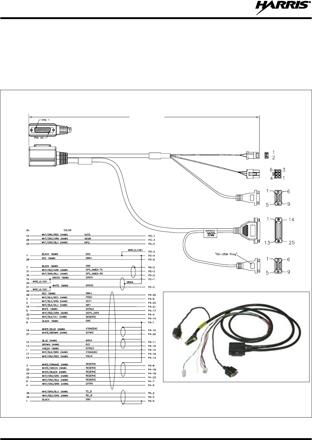
14221-1510-4440
38
10 OPTIONAL CABLES
10.1 OPTION CABLE 14002-0174-08
Option Cable 14002-0174-08 connects to the 44-pin I/O connector on the rear of the radio. It breaks out
into several smaller standardized connectors, allowing straightforward access to external interfaces
provided by the radio. The cable is shown in Figure 10-1 below. The cable’s 44-pin D-subminiature
connector that mates with the connector on the rear of the radio is identified P1.
(Made From D14002-0174 Sh. 11 and 12, Rev. A)
Figure 10-1: Option Cable 14002-0174-08
Approximately 66 inches
(170 centimeters)
ASSEMBLY DIAGRAM
WIRING DIAGRAM
P1
(Pin-Out
View)
P1
(Side
View)
P6
P2
P3
P5
P4
IMAGE
14221-1510-4440
39
Observe caution before connecting any external device to the radio via its 44-pin I/O
connector. If an external device has its own DC power source/cable (i.e., if it is
powered separately from the radio), both the radio and the external device must be
properly grounded before connecting the two units and before making a positive (+)
power connection to either unit. Otherwise, fuse(s) inside the radio may fail (open)
and/or other equipment damage could occur.
Connector P2 is the cable’s 2-pin connector that provided connections for an optional speaker.
Connection is not required if only the radio’s internal speaker will be used.
Connector P3, the cable’s 6-pin connector, is a connector for basic accessories (e.g., hookswitch, etc.).
Connector P4, the cable’s D-subminiature 25-pin connector, provides audio and data connections for
optional equipment.
Connector P5, a D-subminiature 9-pin connector, provides NMEA-formatted GPS serial data connections
for the external computer processing the NMEA-formatted GPS data received by the radio’s internal GPS
receiver. See Section 11 on page 44 for additional information. This is serial port A of the radio.
Connector P6 provides a serial data interface used for radio programming. Like P5, this is a
D-subminiature 9-pin connector. This is serial port B of the radio.
Table 10-1: Option Cable 14002-0174-08 Interconnections
44-PIN I/O
CABLE
CONNECTOR
P1 PIN
SIGNAL
NAME TO/FROM DESCRIPTION
19 SPKR1 P2 pin 1 Speaker Audio Outputs 1 and 2 (differential). This output
can be used
to drive an optional external/remote speaker connected to the radio.
Enable/Disable this and the radio’s internal speaker via
Radio
Personality Manager (RPM).
By default, only the internal speaker is
enabled.
20
21 SPKR2 P2 pin 2
22
10 OUT2 P3 pin 1
Digital Output 2 for auxiliary control. Open-collector, 10 milliamps /
16
volts maximum. External pull-up resistor needed if required by
the
external device’s input during the high/off state.
Use P3 pin 2 or 4 for
ground.
C
onfigure via the “External Output Control Line 2” in RPM’s External
I/O dialog box. For example, an external logging recorder’s
record
enable/disable input can be controlled by setting “
External Output
Control Line 2” to “Extern. Tx Indicator.”
7 GND P3 pins 2 & 4 Chassis Ground.
26 HKSW P3 pin 3 Digital Input for Hookswitch. Active = Ground. Inactive = Open.
25 INP2 P3 pin 5
Digital Input 2. Active = Ground. Inactive =
Open. Use P3 pin 2 or
4 for ground.
C
onfigure via the “Auxiliary Input 2” in RPM’s External I/O dialog
Box.
28 SWA+ P3 pin 6 Switched A+ Output. Approximately 12 volts DC.
8 GND P4 pin 1 Chassis Ground.
CAUTION
14221-1510-4440
40
Table 10-1: Option Cable 14002-0174-08 Interconnections
44-PIN I/O
CABLE
CONNECTOR
P1 PIN
SIGNAL
NAME TO/FROM DESCRIPTION
30 DGPS_
DATA P4 pin 4 NMEA-Formatted GPS
Receiver Module DGPS Correction Data
Serial Data Input. ±15-volt RS-232 input level.
4 EXTRX P4 pin 5 External Rx Audio Input (from external/2nd receiver; summed
;
typically not used).
9 (reserved) P4 pin 7 Pin is not used.
3 (reserved) P4 pin 8 Pin is not used.
5 FDISC P4 pin 9
Buffered Filtered Discriminator Audio Output (typically not used
). A
fixed-level audio output with DC bias. Approximately 200 mV
rms
into a 600-ohm load at rated deviation. Does not
contain signaling
(e.g., CTCSS). Mutes when speaker mutes. Use a 33 µF / 50
V (or
greater) AC-coupling capacitor to couple to a 600-
ohm load. Use
P4 pin 12 for ground.
13 ALO P4 pin 10 MICHI is a microphone audio input, the same as the front/main
mic. 82 mV rms produces SRD. 600-ohm input impedance.
Typically not used. ALO is ground/return for MICHI.
12 MICHI P4 pin 11
1 SUPGND P4 pin 12 Low-power audio output for an optional external
amplifier and
speaker. VOLHI is a single-ended AC‑coupled audio signal
. Use
SUPGND as return/ground for VOLHI
. Rated audio signal level is
approximately 500 mV rms.
14 VOLHI P4 pin 13
15 (reserved) P4 pin 14 Pin is not used.
16 XTONEENC P4 pin 15 External Tone Encode Audio Input. Reference input audio level
is
220 mV rms. 47k ohm input impedance.
17 XTONEDEC P4 pin 16 External Tone Decode Audio Output.
6 EXTALO P4 pin 17 Reference/Ground for external audio (EXTMIC).
24 (reserved) P4 pin 18 Pin is not used.
23 (reserved) P4 pin 19 Pin is not used.
18 INP1 P4 pin 21
Digital Input 1. Active = Ground. Inactive =
Open. Use P4 pin 1 for
ground.
Configure via the “Auxiliary Input 1” in RPM’s External I/O dialog box.
2 OUT1 P4 pin 22
Digital Output 1 for auxiliary control. Open-collector,
10 milliamps / 16
volts maximum. External pull-
up resistor needed if required by the
external device’s input
during the high/off state. Use P4 pin 1 for
ground.
C
onfigure via the “External Output Control Line 1” in Radio
Personality Manager’s (RPM’s) External I/O dialog Box.
29 (reserved) P4 pin 23 Pin is not used.
27 EXTMIC P4 pin 24 External/Auxiliary Mic Audio Input. Reference input audio level
is
82 mV rms. 2.2k ohm input impedance. Use P4 pin 17 for ground.
28 SWA+ P4 pin 25 Switched A+ DC Power Output. Typically, this output is not used.
14221-1510-4440
41
Table 10-1: Option Cable 14002-0174-08 Interconnections
44-PIN I/O
CABLE
CONNECTOR
P1 PIN
SIGNAL
NAME TO/FROM DESCRIPTION
32 GPS_NMEA
_RX P5 pin 2 NMEA-Formatted GPS Receiver Position Data Serial Data Output.
±5-volt minimum RS-232 output level; ±5.4-volt typical.
31 GPS_NMEA
_TX P5 pin 3 NMEA-
Formatted GPS Receiver Module Initialization Data Serial
Data Input. ±15-volt RS-232 input level.
7 GND P5 pin 5 Ground for GPS Serial Data Signals.
33 MIC_NOISE (none)
Background noise microphone input (MIC_NOISE) and input
ground/reference (MIC_NOISE_ALO). As of the publication of this
manual, this input/function is not supported. 600-
ohm input
impedance. MIC_NOISE_ALO is connected to ground.
36 MIC_NOISE
_ALO (none)
38 TD_B P6 pin 2
Transmit Data, Receive Data, Clear-To-Send, and Ready-To-
Send,
and Ground/Reference lines for serial port B. This radio programming
port is active when the front panel mic connector’s sense pin is not
grounded. This port’s Clear-To-Send and Ready-To-Send
handshake
lines are not available at P6.
39 RD_B P6 pin 3
42 CTS_B (none)
43 RTS_B (none)
1 GND P6 pin 5
11, 34, 35, 37,
40, 41 and 44 (reserved) (none) These pins are not used.
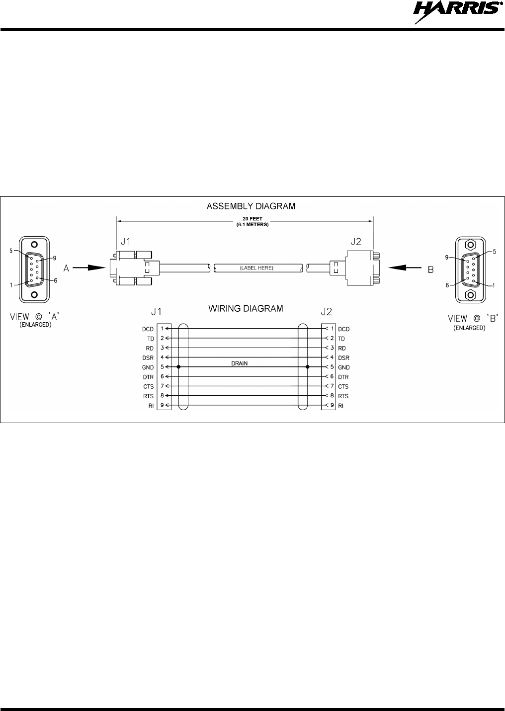
14221-1510-4440
42
10.2 SERIAL DATA CABLE CA-013671-020
Serial Data Cable CA-013671-020 (20 feet long) can be used to extend data connections from the radio to
data communications equipment such as a Mobile Data Terminal (MDT) or a GPS NMEA-format device.
The cable’s assembly and wiring diagrams are shown in Figure 10-2 below.
The cable’s male DB-9 connector (J1) mates to a female DB-9 serial port connector of Option Cable
14002-0174-08, either connector P5 or P6.
The cable’s female DB-9 connector (J2) mates to a PC’s male DB-9 serial port connector. If the utilized
PC is not equipped with a DB-9 serial port connector, the use of a suitable adapter is required, such as
USB-to-RS-232 Adapter Cable CN24741-0001. As of the publication of this manual, CN24741-0001 is
available via the Customer Care center; refer to Section 3.4 on page 11 for contact information.
(Made From PS-CA-013671 Rev. -)
Figure 10-2: Serial Data Cable CA-013671-020
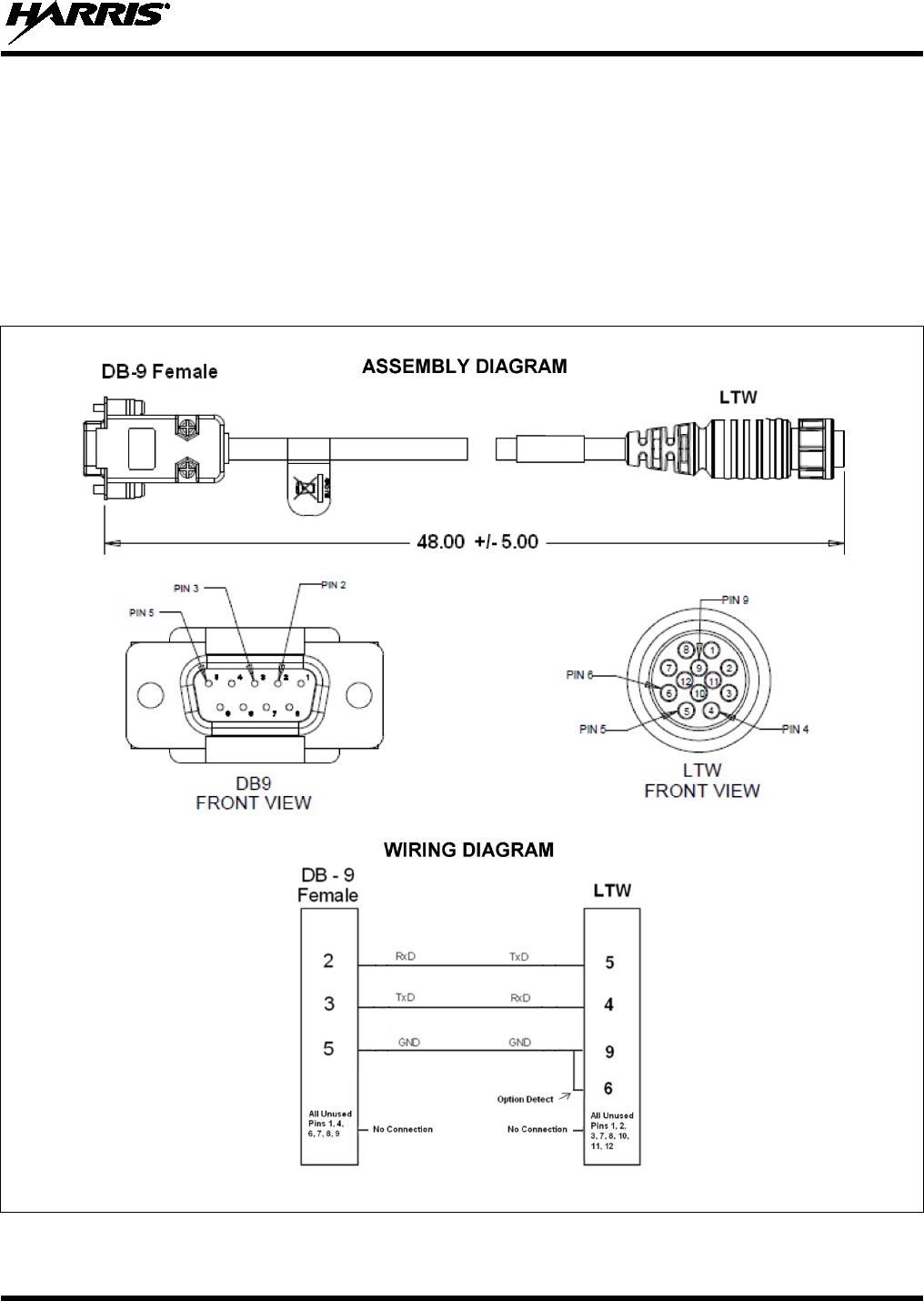
14221-1510-4440
43
10.3 FRONT PANEL PROGRAMMING CABLE 14015-0200-01
Front Panel Programming Cable 14015-0200-01 can be used to program and configure the radio via the
microphone connector on the front panel of the radio. The cable’s assembly and wiring diagrams are
shown in Figure 10-3 below.
The cable’s circular (LTW) connector mates to the radio’s mic connector, and its female DB-9 connector
mates to a male DB-9 serial port connector of a computer (or USB adapter). If the utilized PC is not
equipped with a male DB-9 serial port connector, the use of a suitable adapter is required, such as
USB-to-RS-232 Adapter Cable CN24741-0001. As of the publication of this manual, CN24741-0001 is
available via the Customer Care center; refer to Section 3.4 on page 11 for contact information.
(Made From D14015-0200-PS Rev. -)
Figure 10-3: Front Panel Programming Cable 14015-0200-01
14221-1510-4440
44
11 GPS NMEA-FORMATTED DATA CONNECTION
To obtain GPS NMEA-formatted serial data from the radio, the radio must be equipped with the GPS
receiver option, and Option Cable 14002-0174-08 is required. For radios equipped with a GPS receiver,
follow this procedure to complete the GPS NMEA-formatted serial data connections:
1. Obtain Option Cable 14002-0174-08. Each “leg” of this cable is approximately 65 inches long (166
centimeters).
2. Connect the cable’s 44-pin D-subminiature (DB-44) male connector to the DB-44 female connector
on the rear panel of the radio. Tighten the two jackscrews with a small flathead screwdriver. Do not
over-tighten.
3. Connect the cable’s DB-9 female connector identified as P5 to the computer’s serial port DB-9 male
connector—either directly or extended via cable CA-013671-020 (a 20-foot-long cable); see Section
10.2. Tighten the screws firmly, and then route the cabling as required. If the computer is not
equipped with a DB-9 serial port connector, the use of a suitable adapter is required, such as
USB-to-RS-232 Adapter Cable CN24741-0001.
4. Follow the manufacturer’s instructions on processing the NMEA-formatted GPS data from the radio.
If the Option Cable 14002-0174-08 is not available, a 3-wire serial cable can be field-
fabricated. On the radio end, this cable must interface to the three GPS-related signals of
the radio’s 44-pin I/O Cable connector (pins 7, 31, and 32). See Table 10-1 for additional
information.
Industry software to process GPS information through this interface is not supported by Harris.
12 MOBILE DATA CONNECTION
If the radio installation must support mobile data communications of a computer running Mobile Data
Terminal (MDT) or similar software, follow this procedure to connect the computer to the radio:
1. Obtain Option Cable 14002-0174-08. Each “leg” of this cable is approximately 65 inches long (166
centimeters).
2. Connect the cable’s 44-pin D-subminiature (DB-44) male connector to the DB-44 female connector
on the rear panel of the radio. Tighten the two jackscrews with a small flathead screwdriver. Do not
over-tighten.
3. Route the “leg” of this cable that has the two DB connectors (i.e., DB-25 connector P4 and DB-9
connector P6) to the area near the serial port of the MDT computer. Protect the cable from possible
chafing and tie-and-stow it as necessary.
If the cable’s “leg” length is not long enough to reach the computer, obtain cable
CA-013671-020 (or equivalent) and use it to extend the connection from the DB-9
connector P6. Cable CA-013671-020 is a 20-foot-long standard DB-9 serial data cable.
4. Connect the female DB-9 connector to the computer. If the computer is not equipped with a DB-9
serial port connector, use a suitable adapter, such as USB-to-RS-232 Adapter Cable CN24741-0001.
Before data communications can occur on a P25 system, the respective data option must
be enabled. Contact the Technical Assistance Center (TAC) for additional information.
TAC contact information is included on page 11.
NOTE
NOTE
NOTE

14221-1510-4440
45
13 INITIAL POWER-UP TEST
1. At the radio’s main waterproof (HFB-type) fuse holder installed near the vehicle battery, insert the
15-amp fuse that was included with the radio’s DC Power Cable.
2. Tie and stow all fuse holders at this location to prevent excess vibration/movement.
3. Carefully reconnect the vehicle’s battery ground cable.
4. If not already, temporarily connect the mobile antenna cable from the vehicle-mounted mobile
antenna to the female TNC RF connector on the rear panel of the radio. This is a temporary
connection until test procedures in Section 14 are complete.
5. If the radio is equipped with the GPS receiver option, permanently connect the antenna cable from the
GPS antenna (or mobile/GPS combo antenna) to the female SMA connector on the rear panel of the
radio. The male SMA connector on most GPS antenna cables has a 5/16-inch hex collar, so the use of a
wrench of this same size is normally required for tightening. However, some may have collars with
only knurled surfaces, so a standard wrench or torque wrench cannot be used. In either case, do not
over tighten the connector and do not twist the cable when tightening.
6. If the installation is wired so the vehicle’s ignition key/switch turns the radio on and off, turn the
switch to the Accessory or Run position.
7. If the radio is not already powered up, do so by rotating its on/off/volume control clockwise out of the
detent position.
8. Verify the radio has powered-up by observing its display. If the display is not functioning, refer to
Section 7.2.1 as necessary.
As long as the software configuration parameters have been loaded, successful installation is almost
immediately realized:
• After a short boot-up sequence, the radio displays login information and/or a talk group.
• If no errors are displayed, the installation is most-likely properly wired.
• If an error is displayed, recheck all cable connections, verify all fuses are properly installed, and
verify battery power on the load side of the fuses, etc. If problems persist, contact the Technical
Assistance Center (see page 11).
• Consult the Operator’s Manual for operational information.
Refer to Section 14 for performance test information.
14221-1510-4440
46
14 PERFORMANCE TESTS
This section includes procedures to verify the performance of the installation’s mobile antenna system.
There are three (3) procedures in this section:
• Changing Operating Mode for Tests
• Testing by Transmitting into a Dummy Load (a 50-Ohm RF Terminator)
• Testing by Transmitting into the Mobile Antenna
The accuracy of test results depends upon a DC power source in the range of 13.6 volts
DC ±10%. The current capacity of the power source must be greater than 15 amps.
Make sure the vehicle’s battery is fully charged by running the engine for a few
minutes before the test, and keep the engine running during the test procedures. Abide
by the following WARNING!
If the vehicle’s engine must remain running, the vehicle location should be well
ventilated so exhaust fumes from the engine do not cause harm!
If a vehicle equipped with this radio requires jump-starting, the radio installation’s
main fuse should be removed from the holder prior to jump-starting. Doing so will
prevent damage to the radio system.
Prior to installation, the radio’s power level should be configured appropriately. The
wide range of power levels indicated in the following procedures takes into account
such things as: customer’s requirements; measurement errors, especially to include
uncalibrated equipment; cabling losses; and voltage and temperature variations. By no
means should the result from Performance Testing in this section be construed as the
exact value of power level output from the radio, as the value is set and more
accurately measured in the factory. The values obtained in these test procedures
determine a successful installation only.
CAUTION
WARNING
CAUTION
NOTE
14221-1510-4440
47
14.1 REQUIRED TEST EQUIPMENT
Table 14-1: Test Equipment Required for Performance Tests
TEST EQUIPMENT MODEL / PART NUMBER & DESCRIPTION
Average-Responding
Wattmeter
(for conv. measurements)
Bird Electronic Corp. Model 43 (or equivalent) with Type
N female
connectors at input and output ports.
Digital Wattmeter Bird Electronics Corp Model 5000-XT with Wideband Power Sensor 5017,
25 MHz to 1000 MHz Range.
Wattmeter
Element
(Typically Not Required if
Using a Digital Wattmeter)
For VHF Radio: Bird Electronic Corp. Element 100C (100-
Watt max.),
100 - 250 MHz frequency range (or equivalent).
For 700 & 800 MHz Radio: Bird Electronic Corp. Element 50E (50-Watt max.),
400 - 1000 MHz frequency range (or equivalent).
RF Coaxial
Jumper Cable
Pasternack Enterprises PE3661-36 (or equivalent) 50-Ohm Coaxial Cable
with TNC male connector and Type N male connector, approximately three
(3) feet in length. The utilized cable must have VSWR below 1.5:1 within
the RF passband.
N-to-TNC
RF Adapter
Pasternack Enterprises PE9090 (or equivalent) Type N male to TNC female
adapter. Required to connect the cable of the vehicle-mounted antenna to
the wattmeter.
50-Ohm RF Terminator
(“Dummy Load”) Pasternack Enterprises PE6167 (or equivalent) 50-ohm RF terminator rated
at 50 watts or greater, with Type N male connector.
Vehicle-Mounted
Antenna Tests are performed with the vehicle-mounted antenna per the installation
described in Section 6 of this manual.
14.2 TRANSMITTING INTO A DUMMY LOAD
1. Using the Type N male to TNC male RF coaxial jumper cable, connect the radio’s antenna connector
to the wattmeter’s input connector. Refer to Figure 14-1 as necessary.
2. Connect the 50-ohm dummy load to the wattmeter’s output connector, in place of the antenna cable
from the vehicle-mounted antenna.
As previously stated, if conventional mode is not available per radio programming, a peak-
reading RF wattmeter is required to measure RF transmit power. Otherwise, the use of an
average-responding wattmeter is recommended. See Table 14-1.
3. If not already, turn the radio on and set it to the required operating mode (based upon available radio
programming and test equipment).
4. Set the radio to a test talk group or conventional channel, if available.
5. Position the wattmeter’s element to measure forward RF output power. Rotate it if necessary. The
arrow on the face of the element must point away from the radio and towards the dummy load for
forward power measurements.
6. Set the wattmeter to measure average RF power.
It is recommended that a test talk group/channel be allocated for this testing. This same
group should be used during the antenna test procedure which is presented in the
subsequent section.
NOTE
NOTE
or
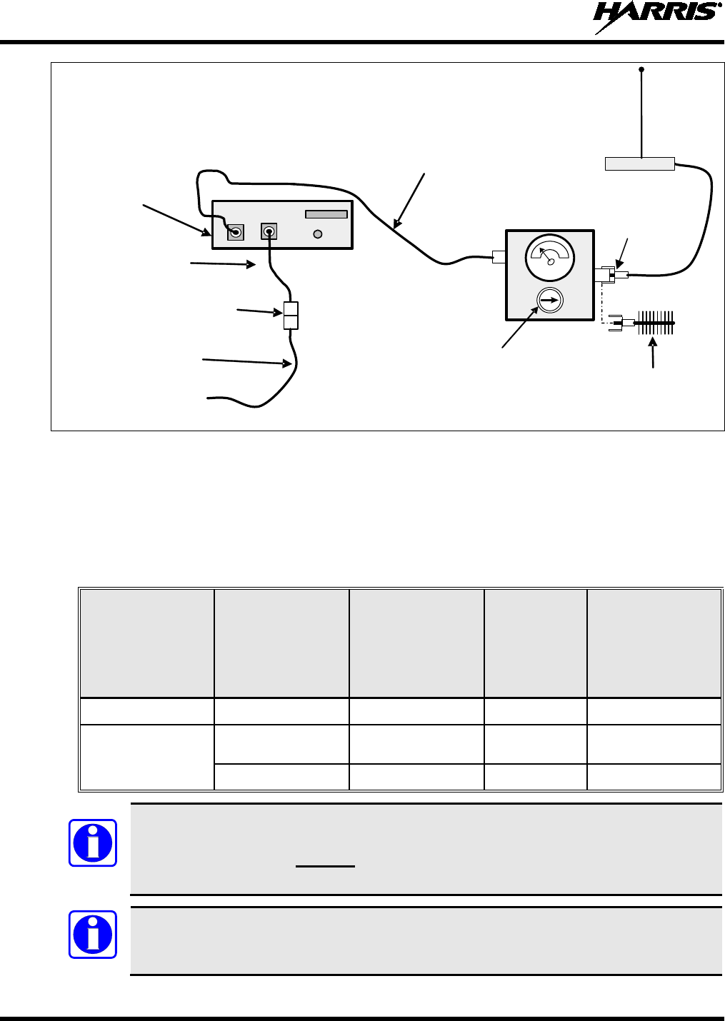
14221-1510-4440
48
IN
OUT
XG-25M
Mobile Radio
(Rear View)
Radio’s DC
Power Cable
3-Pin
Connectors
Installation’s DC
Power Cable
From 13.8-Volt Fused
Power Source
TNC Male-to-Type N Male
Coaxial Jumper Cable
Option Cable and GPS
Antenna Cable
connections not are
indicated.
Vehicle-Mounted Antenna
Type N Male-to-
TNC Female
RF Adapter
Wattmeter
50-Ohm RF
Terminator
(“Dummy Load”)
Wattmeter Element –
Shown Positioned for
Forward Power
Measurements
(see text)
Figure 14-1: Wattmeter Connections for Antenna System Tests
7. Key the radio’s transmitter via the microphone’s PTT button.
8. Verify the measured transmit output power is within the respective range listed in Table 14-2. The
respective power setting listed in this table assumes the radio is currently configured at the maximum
transmit power level.
Table 14-2: Transmit Power Ranges with Radio Maximum Power Levels
RADIO
MAXIMUM
TRANSMIT
POWER
APPLICABLE
RF BANDS
MINIMUM
MEASURED
TRANSMIT
OUTPUT POWER
(Watts)
(-1 dB)
TRANSMIT
OUTPUT
POWER
SETTING
(Watts)
MAXIMUM
MEASURED
TRANSMIT
OUTPUT POWER
(Watts)
(+1 dB)
50 Watts VHF 39.8 50 63
35 Watts 700 MHz 23.8 30
(see NOTE) 37.7
800 MHz 27.8 35 44.1
The 700/800 MHz radio is aligned for a maximum of 35 watts across its entire RF
operating range. However, for FCC licensed systems, verify the radio’s
700 MHz
channels are limited to 30 Watts. This is accomplished via radio personality program-
ming.
Transmit only for as long as needed to take the measurement, then immediately disable the
transmission.
NOTE
NOTE
14221-1510-4440
49
9. If the wattmeter reading is within the range, record the measured value in the appropriate space on
the data collection form near the end of this manual.
If the wattmeter reading is outside the range, verify the radio’s power supply voltage (i.e., battery
voltage) is within the specified range, recheck all connections, and measure the RF output power
again. If this fails to produce a reading within the range, replace it and repeat this procedure. If
problems persist, contact the Technical Assistance Center (see page 11).
14.3 TRANSMITTING INTO THE MOBILE ANTENNA
1. Connect the antenna cable from the vehicle-mounted antenna to the wattmeter as shown in Figure
14-1.
2. If not already, turn the radio on and set it to the required operating mode (based upon available radio
programming and test equipment).
3. Set the radio to a test talk group or conventional channel, if available.
It is recommended that a test talk group/channel be allocated for this testing.
Otherwise, interference with other radio users in the system may occur. Also, during
transmissions, always observe the RF exposure-
related safety information
presented in XG-25M radio’s Product Safety Manual.
4. Position the wattmeter’s element to measure forward RF output power. Rotate it if necessary. The
arrow on the face of the element must point away from the radio and towards the antenna for forward
power measurements.
5. Set the wattmeter to measure average RF power.
6. Key the radio’s transmitter via the microphone’s PTT button.
7. Verify the measured transmit output power is within the respective range listed in Table 14-2. The
respective power setting listed in this table assumes the radio is currently configured at the maximum
transmit power level.
Transmit only for as long as needed to take the measurement, then immediately
disable the transmission.
8. If the wattmeter reading is within the range, record the value in the appropriate space on the data
collection form near the end of this manual.
If the wattmeter reading is outside the range, verify the radio’s power supply voltage (i.e., battery
voltage) is within the specified range, recheck all connections, and measure the forward power again.
If the installation employs a ¼-wave unity-gain antenna, observe the following NOTE. If these
checks/corrections fail to produce a reading within the range, check all cabling and connections and
repeat the testing procedure to this point. In the event the wattmeter reading still falls outside the
range, replace the antenna, make sure all connections are seated firmly, and repeat the testing
procedure. If problems persist, contact the Technical Assistance Center (see page 11).
If the radio installation employs a ¼-wave unity-gain antenna (part number AN-
225006-001
), the driven element (i.e., whip) of the antenna must be trimmed to the
proper length in order to minimize antenna system VSWR. Refer to the instructions
included with the antenna for trimming instructions.
NOTE
NOTE
NOTE
14221-1510-4440
50
9. Position the wattmeter’s element to measure reverse (reflected) RF power from the antenna. The
arrow on the face of the element must point away from the antenna and to the radio to measure
reverse power.
10. Key the radio’s transmitter via the microphone’s PTT button.
11. Compare the wattmeter reading with the RF power output range of 2 watts or less.
Transmit only for as long as needed to take the measurement, then immediately disable
the transmission.
12. If the wattmeter reading is within the range, record the value in the appropriate space on the data
collection form near the end of this manual.
If the wattmeter reading is outside the range, make sure the antenna is consistent with the specified
frequency range of the radio. Recheck all antenna connections, and measure the reverse power again.
If the installation employs a ¼-wave unity-gain antenna, observe the NOTE that immediately follows
step 8. If these checks/corrections fail to produce a reading within the range, replace the antenna and
repeat the entire antenna test procedure. Any value exceeding the maximum allowable reflected
power value will result in a diminished RF output signal. If problems persist, contact the Technical
Assistance Center (see page 11).
13. Disconnect the coaxial cable jumper and wattmeter.
14. Permanently connect the cable from the vehicle-mounted antenna to the radio’s antenna cable by
mating the two TNC connectors together. Use two pairs of soft-jaw pliers to gently tighten this
connection. Do not over tighten and do not twist either cable.
15. Make several test calls on the radio system to verify operation of the mobile radio. Before making the
calls, select other talk groups or conventional channels, as required to verify operation.
To prevent RF leakage and ensure peak performance, make sure the RF connectors are
tight, but do not over-tighten so connector damage will not occur.
Improper installation of the RF cables may
lead not only to poor radio
performance but also to harmful exposure to RF electromagnetic energy.
Testing is complete. The radio is now ready for normal communications.
NOTE
NOTE
WARNING
14221-1510-4440
51
14.4 TEST PERFORMANCE DATA FORM
Enter the information requested on this data collection form. Clip this form and file it as a permanent record of
the tested performance of the XG-25M mobile radio installation.
Clip
Here
Company Performing Installation
Technician Performing Test
Date of Test
(mm/dd/yyyy)
Mobile Radio Serial Number
Antenna Make and Model Numbers
Power into a Dummy
Load
Watts
Forward Power with
Antenna
Reflected Power
with Antenna
Watts
Watts

14221-1510-4440
52
15 COMPLETE THE INSTALLATION
Double-check the following items before considering the installation completed:
• Verify all newly installed mechanical hardware is mounted securely and all respective mounting
hardware is tight.
• Verify all electrical interconnections are connected properly and the associated connector attachment
hardware is tight. Pay special attention to all RF antenna cables!
• Verify all related fuses are correctly installed and properly rated.
• Verify all electrical cables and wiring are tied, stowed, and protected so they are out of the way of
casual contact, away from sources of extreme heat, and wire chafing cannot occur. Pay special
attention to all RF antenna cables!
• To prevent fumes from entering the vehicle’s passenger compartment, seal the hole/grommet/wire
combination at the firewall with a silicon-based sealer.
• Verify all vehicle components are properly reinstalled such as kick panels, headliners, and seats.
• If the installation includes a separately-mounted on/off power switch for manually turning the radio
(and possibly other systems) on and off, verify it is labelled accordingly. For example: “Radio
ON/OFF.”
• Remove all tools and unused hardware from the vehicle.
• Verify the test performance data has been recorded on the data collection form shown in this manual.
16 WARRANTY REGISTRATION
Please register this product within ten (10) days of purchase. Registration validates the warranty coverage,
and enables Harris to contact you in case of any safety notifications issued for this product.
Registration can be made on-line at http://www.pspc.harris.com/Service/WarrantySupport.asp.

14221-1510-4440
53
17 WARRANTY
A. Harris Corporation, a Delaware Corporation, through its RF Communications Division (hereinafter
"Seller") warrants to the original purchaser for use (hereinafter "Buyer") that Equipment manufactured
by or for the Seller shall be free from defects in material and workmanship, and shall conform to its
published specifications. With respect to all non-Seller Equipment, Seller gives no warranty, and only
the warranty, if any, given by the manufacturer shall apply. Rechargeable batteries are excluded
from this warranty but are warranted under a separate Rechargeable Battery Warranty (ECR-7048).
B. Seller’s obligations set forth in Paragraph C below shall apply only to failures to meet the above
warranties occurring within the following periods of time from date of sale to the Buyer and are
conditioned on Buyer’s giving written notice to Seller within thirty (30) days of such occurrence:
1. for fuses and non-rechargeable batteries, operable on arrival only.
2. for parts and accessories (except as noted in B.1 and B.5), ninety (90) days.
3. for MBC-100, XG-25P, XG-75, P7300, P7200, P7100IP, P5500, P5400, P5300, P5200, P5100,
P3300, M7300, M7200 (including V-TAC), M7100IP, M5300, M3300 and SG5300 radios, two (2)
years, effective 10/01/2007.
4. for Unity® XG-100P and XG-100M, three (3) years.
5. for Six-Bay battery Chargers (12082-0314-xx and CH-104570-xxx), one (1) year.
6. for all other equipment of Seller’s manufacture, one (1) year.
C. If any Equipment fails to meet the foregoing warranties, Seller shall correct the failure at its option (i)
by repairing any defective or damaged part or parts thereof, (ii) by making available at Seller’s factory
any necessary repaired or replacement parts, or (iii) by replacing the failed Equipment with equivalent
new or refurbished Equipment. Any repaired or replacement part furnished hereunder shall be
warranted for the remainder of the warranty period of the Equipment in which it is installed. Where
such failure cannot be corrected by Seller’s reasonable efforts, the parties will negotiate an equitable
adjustment in price. Labor to perform warranty service will be provided at no charge during the
warranty period only for the Equipment covered under Paragraph B.3, B.4 and B.5. To be eligible for
no-charge labor, service must be performed at Seller’s factory, by an Authorized Service Center
(ASC) or other Servicer approved for these purposes either at its place of business during normal
business hours, for mobile or personal equipment, or at the Buyer’s location, for fixed location
equipment. Service on fixed location equipment more than thirty (30) miles (48 km) from the Service
Center or other approved Servicer’s place of business will include a charge for transportation.
D. Seller’s obligations under Paragraph C shall not apply to any Equipment, or part thereof, which (i) has
been modified or otherwise altered other than pursuant to Seller’s written instructions or written
approval or, (ii) is normally consumed in operation or, (iii) has a normal life inherently shorter than the
warranty periods specified in Paragraph B, or (iv) is not properly stored, installed, used, maintained or
repaired, or, (v) has been subjected to any other kind of misuse or detrimental exposure, or has been
involved in an accident.
E. The preceding paragraphs set forth the exclusive remedies for claims based upon defects in or
nonconformity of the Equipment, whether the claim is in contract, warranty, tort (including
negligence), strict liability or otherwise, and however instituted. Upon the expiration of the warranty
period, all such liability shall terminate. The foregoing warranties are exclusive and in lieu of all other
warranties, whether oral, written, expressed, implied or statutory. NO IMPLIED OR STATUTORY
WARRANTIES OF MERCHANTABILITY OR FITNESS FOR PARTICULAR PURPOSE SHALL
APPLY. IN NO EVENT SHALL THE SELLER BE LIABLE FOR ANY INCIDENTAL,
CONSEQUENTIAL, SPECIAL, INDIRECT OR EXEMPLARY DAMAGES.
This warranty applies only within the United States.
Harris Corporation Harris Corporation
RF Communications Division RF Communications Division
221 Jefferson Ridge Parkway 1680 University Avenue
Lynchburg, VA 24501 Rochester, NY 14610
1-800-368-3277 1-585-244-5830
ECR-7047T